Embed Size (px)
Citation preview

Microelectronics Heat TransferLaboratory
Department of Mechanical EngineeringUniversity of Waterloo
Waterloo, Ontario, Canadahttp://www.mhtl.uwaterloo.ca
Outline
➥ Personnel➥ Capabilities➥ Facilities➥ Research Projects➥ Web-based Modeling Tools

Microelectronics Heat TransferLaboratory
established in 1984 within the Department of Mechanical Engineering at the University of Waterloo research related to heat transfer and other thermodynamic phenomena found in microelectronics & telecommunications applications fully funded through industrial and governmental grants and contracts staff includes: ➣ 1 faculty member + 1 retired faculty member ➣ 2 research engineers ➣ 4 graduate students ➣ 1 post doctoral fellow ➣ 1 technician

Personnel
➤ Richard Culham Associate Professor & Director
➤ Peter Teertstra Research Engineer
➤ Michael Yovanovich, Distinguished Professor Emeritus & Principal Scientific Advisor
Analytical Modeling Capabilities
➥ Conjugate heat transfer for microelectronics➥ Convection and conduction from bodies of
arbitrary shape➥ Thermal contact resistance➥ Thermal spreading resistance➥ Fluid flow and heat transfer for singly and
multiply-connected ducts of arbitrary shape

Experimental Facilities➥ Conjugate heat transfer for packages &
boards➥ Air and liquid cooled heat sink performance➥ Thermal contact & spreading resistance➥ Thermal conductivity measurements➥ Testing of thermal interface materials➥ Surface characterization➥ Radiation heat transfer
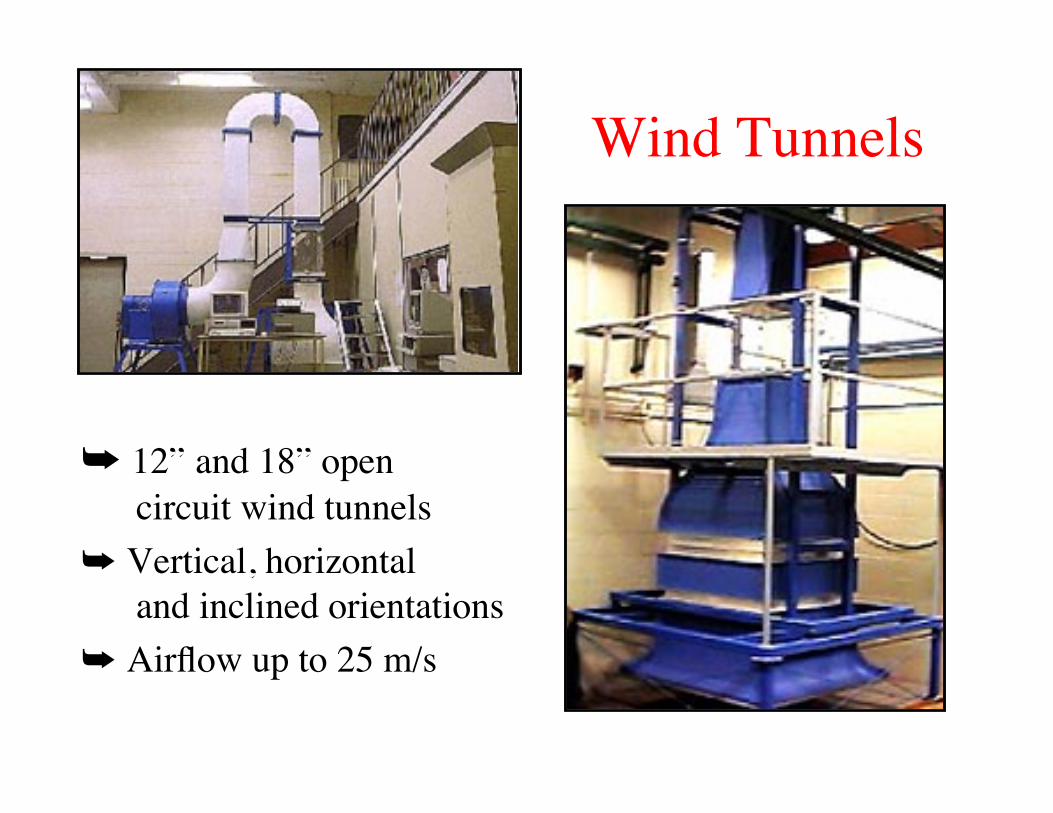
Wind Tunnels
➥ 12” and 18” open circuit wind tunnels
➥ Vertical, horizontal and inclined orientations
➥ Airflow up to 25 m/s
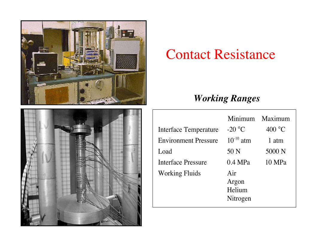
Contact Resistance
Working Ranges
Minimum Maximum
Interface Temperature -20 °C 400 °C
Environment Pressure 10-10 atm 1 atm
Load 50 N 5000 N
Interface Pressure 0.4 MPa 10 MPa
Working Fluids Air
Argon
Helium
Nitrogen

Surface Characterization
➣ Talysurf 5 surface profilometer surface roughness, wavines and profile for flat or circular surfaces calculates RMS roughness & RMS surface slope➣ Taylor Hobson Surtronic 3+ portable surface profilometer resolution ➣ Wyco NT-3300 non-contact, optical surface profiler (Sept. 2000)
0.01 µm ! 300 µm
➣ Leitz Durimet Microhardness Tester indenter loads: 15 - 2000 g sample temperatures: up to 200 C ➣ Hysitron Nano Hardness Tester (Sept. 2000)
o
Computing Facilities
➥ Hardware: ➣ SGI Octane dual processor R10000 workstation ➣ SGI IRIS Indigo R4000 workstation ➣ SGI Origin 200 server/workstation (Sept. 2000) ➣ 8 networked PC’s
➥ Software: ➣ Numerical CFD Simulation: Flotherm, Ideas, Icepack ➣ Symbolic Mathematics: Mathematica, Maple, Matlab ➣ Code Development: Visual Basic, C++, CGI, Java, Javascript

Research Projects➥ Natural convection in microelectronic enclosures➥ Analytical modeling of heat sinks
➣ plate fin and circular annular heat sinks ➣ optimization routines
➥ Modeling of low Reynolds number flow heat exchangers➥ Spreading resistance models
➣ sphere-layered substrate elastic contact ➣ circular & rectangular sources on compound disks and flux channels
➥ Characterization and modelling of thermal interface materials
Natural Convection in Enclosures
Objectives
Overview
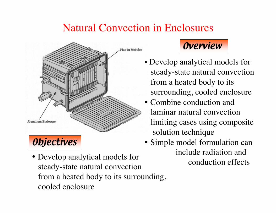
Develop analytical models for steady-state natural convection from a heated body to its surrounding, cooled enclosure
Develop analytical models for steady-state natural convection from a heated body to its surrounding, cooled enclosure Combine conduction and laminar natural convection limiting cases using composite solution technique Simple model formulation can include radiation and conduction effects

Heat Sinks: Plate FinsObjectives
develop a natural convection model for plate fin heat sinks with isothermal or isoflux boundary conditions
Overview
the heat sink geometry is specified using 6 geometric parameters, including fin spacing and thickness, base plate thickness, fin height and length and the total number of fins the heat sink is divided into two distinct regions: inner region - combination of boundary layer and fully developed flow outer region - combination of low Rayleigh flow conduction and boundary layer flow
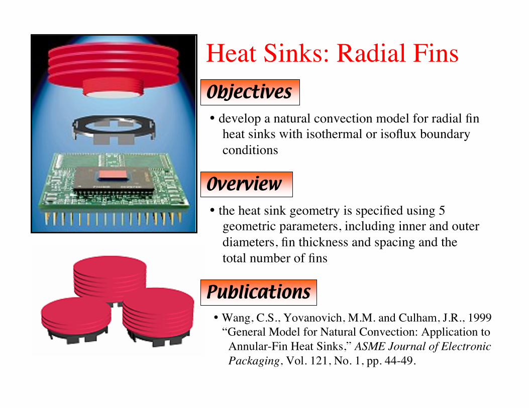
Heat Sinks: Radial FinsObjectives develop a natural convection model for radial fin heat sinks with isothermal or isoflux boundary conditions
Overview the heat sink geometry is specified using 5 geometric parameters, including inner and outer diameters, fin thickness and spacing and the total number of fins
Publications Wang, C.S., Yovanovich, M.M. and Culham, J.R., 1999 “General Model for Natural Convection: Application to Annular-Fin Heat Sinks,” ASME Journal of Electronic Packaging, Vol. 121, No. 1, pp. 44-49.
Heat Sinks: Optimization RoutinesObjectives
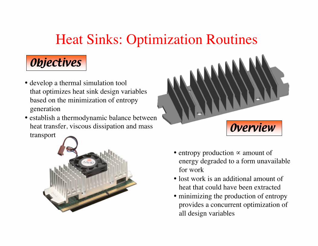
develop a thermal simulation tool that optimizes heat sink design variables based on the minimization of entropy generation establish a thermodynamic balance between heat transfer, viscous dissipation and mass transport
Overview
entropy production ∝ amount of energy degraded to a form unavailable for work lost work is an additional amount of heat that could have been extracted minimizing the production of entropy provides a concurrent optimization of all design variables
Modeling of Low Reynolds FlowHeat Exchangers
Objectives
Overview
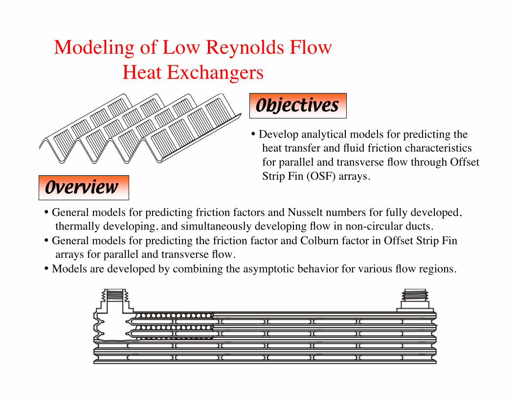
Develop analytical models for predicting the heat transfer and fluid friction characteristics for parallel and transverse flow through Offset Strip Fin (OSF) arrays.
General models for predicting friction factors and Nusselt numbers for fully developed, thermally developing, and simultaneously developing flow in non-circular ducts. General models for predicting the friction factor and Colburn factor in Offset Strip Fin arrays for parallel and transverse flow. Models are developed by combining the asymptotic behavior for various flow regions.
Thermal Constriction Resistance:Sphere-Layered Substrate in Elastic Contact
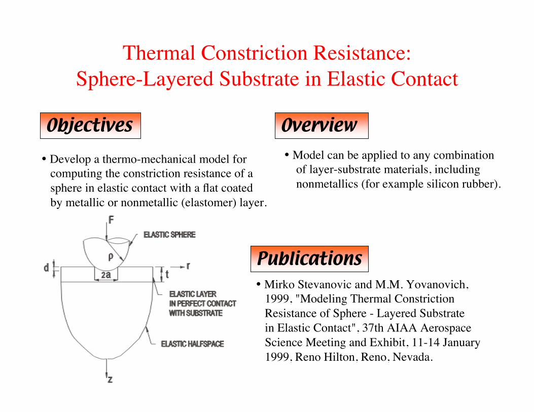
Objectives Overview Model can be applied to any combination of layer-substrate materials, including nonmetallics (for example silicon rubber).
Publications Mirko Stevanovic and M.M. Yovanovich, 1999, "Modeling Thermal Constriction Resistance of Sphere - Layered Substrate in Elastic Contact", 37th AIAA Aerospace Science Meeting and Exhibit, 11-14 January 1999, Reno Hilton, Reno, Nevada.
Develop a thermo-mechanical model for computing the constriction resistance of a sphere in elastic contact with a flat coated by metallic or nonmetallic (elastomer) layer.
Objectives
Overview
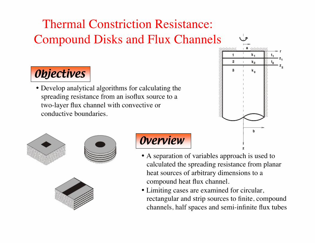
Develop analytical algorithms for calculating the spreading resistance from an isoflux source to a two-layer flux channel with convective or conductive boundaries.
A separation of variables approach is used to calculated the spreading resistance from planar heat sources of arbitrary dimensions to a compound heat flux channel. Limiting cases are examined for circular, rectangular and strip sources to finite, compound channels, half spaces and semi-infinite flux tubes
Thermal Constriction Resistance:Compound Disks and Flux Channels

Web-based Design Tools➥ URL for the MHTL Web page
http://www.mhtl.uwaterloo.ca➥ tool set includes:
➣ natural convection in heat sinks: radial fins, plate fins ➣ spreading resistance: circular source on a compound disk, flux tube or half space rectangular source on a rectangular disk, flux tube or half space ➣ PCB thermal simulation ➣ thermophysical property calculator ➣ special function calculator
➥ coming soon: calculator, friction factor & j-factor for internal flows, slotted-fin heat sinks, and more ...
keffective

Contact Information
➥ Web page: http://www.mhtl.uwaterloo.ca➥ Email: R. Culham: [email protected]
M. Yovanovich: [email protected] P. Teertstra: [email protected]
➥ Phone: (519) 888-4586 Fax: (519) 746-9141
➥Address: Microelectronics Heat Transfer Laboratory Department of Mechanical Engineering University of Waterloo Waterloo, Ontario, Canada N2L 3G1