Embed Size (px)
Citation preview
Microelectronic Circuits, Kyung Hee Univ. Spring, 2016
1
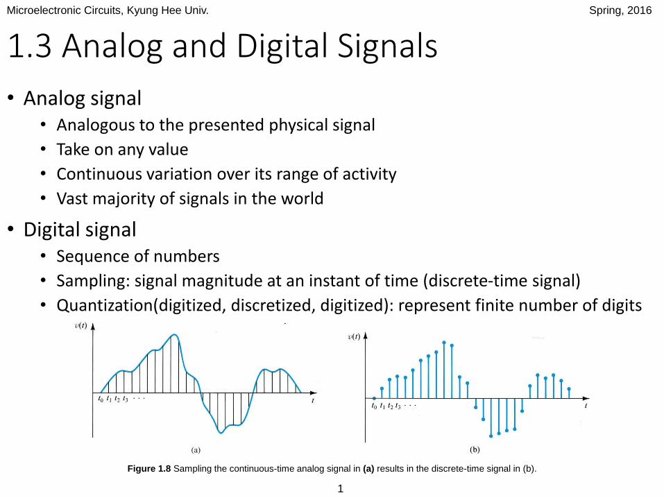
1.3 Analog and Digital Signals
• Analog signal • Analogous to the presented physical signal
• Take on any value
• Continuous variation over its range of activity
• Vast majority of signals in the world
• Digital signal• Sequence of numbers
• Sampling: signal magnitude at an instant of time (discrete-time signal)
• Quantization(digitized, discretized, digitized): represent finite number of digits
Figure 1.8 Sampling the continuous-time analog signal in (a) results in the discrete-time signal in (b).
Microelectronic Circuits, Kyung Hee Univ. Spring, 2016
2
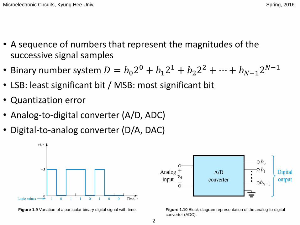
• A sequence of numbers that represent the magnitudes of the successive signal samples
• Binary number system 𝐷 = 𝑏020 + 𝑏12
1 + 𝑏222 +⋯+ 𝑏𝑁−12
𝑁−1
• LSB: least significant bit / MSB: most significant bit
• Quantization error
• Analog-to-digital converter (A/D, ADC)
• Digital-to-analog converter (D/A, DAC)
Figure 1.9 Variation of a particular binary digital signal with time. Figure 1.10 Block-diagram representation of the analog-to-digital
converter (ADC).
Microelectronic Circuits, Kyung Hee Univ. Spring, 2016
3
1.4 Amplifiers
• Signal amplification: the most fundamental signal-processing function
• Amplifier (as a circuit building block)
• Only consider external characteristics
Microelectronic Circuits, Kyung Hee Univ. Spring, 2016
4
1.4.1 Signal Amplification
• Require signal amplification• Transducers provide weak signals (mV or mV)
• For reliable signal processing
→ Signal amplifier
• Linearity: output waveform must be identical to those in the input waveform except of course for having larger magnitude
• Any change in waveform = distortion
• 𝑣𝑜 𝑡 = 𝐴𝑣𝑖 𝑡
• A: amplifier gain
• Linear amplifier
• Voltage amplifier (preamplifier in the home stereo system)
• Power amplifier (provide only a modest amount of voltage gain but substantial current gain)
Microelectronic Circuits, Kyung Hee Univ. Spring, 2016
5
1.4.2 Amplifier Circuit Symbol
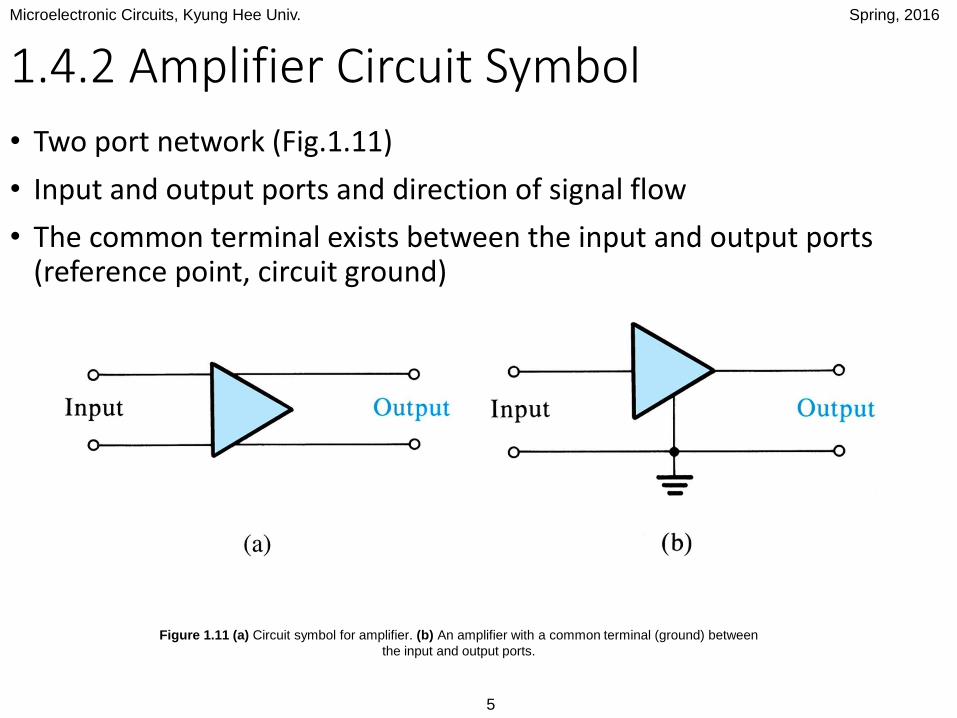
• Two port network (Fig.1.11)
• Input and output ports and direction of signal flow
• The common terminal exists between the input and output ports (reference point, circuit ground)
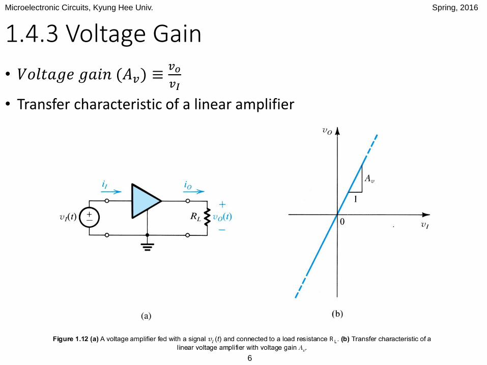
Figure 1.11 (a) Circuit symbol for amplifier. (b) An amplifier with a common terminal (ground) between
the input and output ports.
Microelectronic Circuits, Kyung Hee Univ. Spring, 2016
6
1.4.3 Voltage Gain
• 𝑉𝑜𝑙𝑡𝑎𝑔𝑒 𝑔𝑎𝑖𝑛 (𝐴𝑣) ≡𝑣𝑜
𝑣𝐼
• Transfer characteristic of a linear amplifier
Microelectronic Circuits, Kyung Hee Univ. Spring, 2016
7
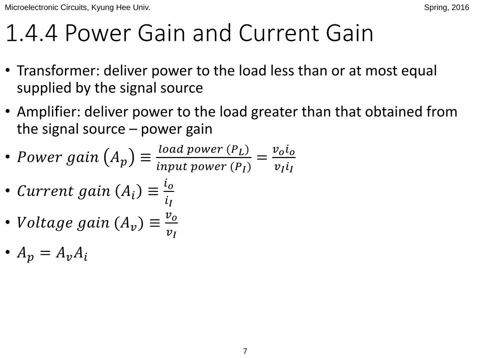
1.4.4 Power Gain and Current Gain
• Transformer: deliver power to the load less than or at most equal supplied by the signal source
• Amplifier: deliver power to the load greater than that obtained from the signal source – power gain
• 𝑃𝑜𝑤𝑒𝑟 𝑔𝑎𝑖𝑛 𝐴𝑝 ≡𝑙𝑜𝑎𝑑 𝑝𝑜𝑤𝑒𝑟 (𝑃𝐿)
𝑖𝑛𝑝𝑢𝑡 𝑝𝑜𝑤𝑒𝑟 (𝑃𝐼)=
𝑣𝑜𝑖𝑜
𝑣𝐼𝑖𝐼
• 𝐶𝑢𝑟𝑟𝑒𝑛𝑡 𝑔𝑎𝑖𝑛 𝐴𝑖 ≡𝑖𝑜
𝑖𝐼
• 𝑉𝑜𝑙𝑡𝑎𝑔𝑒 𝑔𝑎𝑖𝑛 (𝐴𝑣) ≡𝑣𝑜
𝑣𝐼
• 𝐴𝑝 = 𝐴𝑣𝐴𝑖
Microelectronic Circuits, Kyung Hee Univ. Spring, 2016
8
1.4.5 Expressing Gain in Decibels
• Ratios of similarly dimensioned quantities
• Dimensionless numbers (V/V, A/A, W/W)
• Express amplifier gain with a logarithmic measure
• 𝑉𝑜𝑙𝑡𝑎𝑔𝑒 𝑔𝑎𝑖𝑛 𝑖𝑛 𝑑𝑒𝑐𝑖𝑏𝑒𝑙𝑠 = 20 log 𝐴𝑣 𝑑𝐵
• 𝐶𝑢𝑟𝑟𝑒𝑛𝑡 𝑔𝑎𝑖𝑛 𝑖𝑛 𝑑𝑒𝑐𝑖𝑏𝑒𝑙𝑠 = 20 log 𝐴𝑖 𝑑𝐵
• 𝑃𝑜𝑤𝑒𝑟 𝑔𝑎𝑖𝑛 𝑖𝑛 𝑑𝑒𝑐𝑖𝑏𝑒𝑙𝑠 = 10 log 𝐴𝑝 𝑑𝐵
• Negative gain 𝐴𝑣: 180° phase difference between input and output signals (not attenuating)
• -20 dB: attenuating the input signal by a factor of 10 (𝐴𝑣 = 0.1 𝑉/𝑉)
Microelectronic Circuits, Kyung Hee Univ. Spring, 2016
9
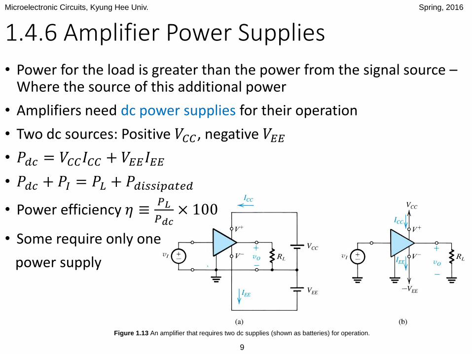
1.4.6 Amplifier Power Supplies
Figure 1.13 An amplifier that requires two dc supplies (shown as batteries) for operation.
• Power for the load is greater than the power from the signal source –Where the source of this additional power
• Amplifiers need dc power supplies for their operation
• Two dc sources: Positive 𝑉𝐶𝐶, negative 𝑉𝐸𝐸
• 𝑃𝑑𝑐 = 𝑉𝐶𝐶𝐼𝐶𝐶 + 𝑉𝐸𝐸𝐼𝐸𝐸
• 𝑃𝑑𝑐 + 𝑃𝐼 = 𝑃𝐿 + 𝑃𝑑𝑖𝑠𝑠𝑖𝑝𝑎𝑡𝑒𝑑
• Power efficiency 𝜂 ≡𝑃𝐿
𝑃𝑑𝑐× 100
• Some require only one
power supply

Microelectronic Circuits, Kyung Hee Univ. Spring, 2016
10
1.4.7 Amplifier Saturation
• Linearity in amplifier transfer characteristic within a limited range of input and output voltages
• Positive and negative saturation levels: 𝐿+, 𝐿−• Within a fraction of a volt of the voltage of the corresponding power supply
• To avoid distorting the output signal, input signal swing within the linear range of operation
•𝐿−
𝐴𝑣≤ 𝑣𝐼 ≤
𝐿+
𝐴𝑣
• If lager, output was clipped off
Figure 1.14 An amplifier transfer characteristic that is linear except
for output saturation.
Microelectronic Circuits, Kyung Hee Univ. Spring, 2016
11
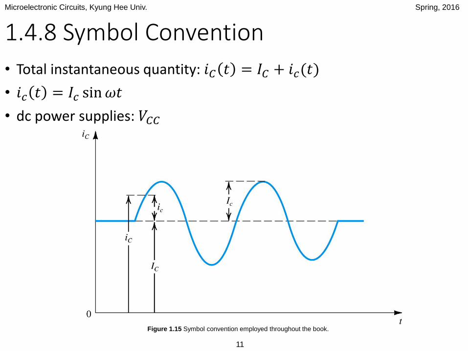
1.4.8 Symbol Convention
• Total instantaneous quantity: 𝑖𝐶 𝑡 = 𝐼𝐶 + 𝑖𝑐(𝑡)
• 𝑖𝑐 𝑡 = 𝐼𝑐 sin𝜔𝑡
• dc power supplies: 𝑉𝐶𝐶
Figure 1.15 Symbol convention employed throughout the book.
Microelectronic Circuits, Kyung Hee Univ. Spring, 2016
12
Homework
• Exercise 1.9, 1.10, 1.11
• Example 1.2