Embed Size (px)
Citation preview
Microdrive V Technical Manual PDL Part No.4201-242 Rev A
MICRODRIVE V TECHNICAL MANUALPART NO. 4201-242 REV A
Head Office:81 Austin StreetP.O. Box 741NapierNew ZealandTel.: +64-6-843-5855Fax.: +64-6-843-518542
01-0
03 R
ev C
Pag
e 1
of 8

Microdrive V Technical Manual PDL Part No.4201-242 Rev A
4201
-003
Rev
CP
age
2 of
8

Microdrive V Technical Manual PDL Part No.4201-242 Rev A
IMPORTANT NOTES
SAFETY WARNINGS:
– It is the installer’s responsibility to ensure the configuration and installation of the Microdrive V Series meets therequirements of any site specific, local and national electrical regulations.
– The Microdrive V Series operates from HIGH VOLTAGE, HIGH ENERGY ELECTRICAL SUPPLIES. Storedcharge is present after switch off.
– Due to the high leakage currents inherent to AC drives, earth connection of both the motor and the Microdrive VSeries is essential before connection to the supply. The Microdrive V Series must be permanently connected tothe supply.
– For safety reasons, normal operation of the Microdrive V Series requires front covers/doors to be in place andsecured closed.
– Do not attempt to isolate the motor while the Microdrive V Series is running.
– Some parameter settings may cause the Microdrive V Series to start automatically after power failure.
– Motor overspeed operation may be limited by mechanical constraints.
RELIABILITY WARNINGS:
– Always screen control wiring.
– Ensure that the Microdrive V Series is not mounted in an adverse environment.
SERVICING WARNINGS:
– Service only by qualified personnel.
– Always isolate and allow to discharge before servicing.
– Never replace ceramic fuses with glass types.
– Always wear safety glasses when operating with the cover removed.
– The Microdrive V Series contains static sensitive printed circuit boards. Use static safe procedures whenhandling these boards.
– Never work on live equipment alone.
– Observe all recommended practices.
NOTES:
– It is the responsibility of the end user/purchaser to ensure that operators understand how to use this equipmentsafely. Please read this manual thoroughly.
4201
-003
Rev
CP
age
3 of
8

Microdrive V Technical Manual PDL Part No.4201-242 Rev A
4201
-003
Rev
CP
age
4 of
8
DEDICATION TO QUALITY
AC Motor Control Products can dramatically improve your process control, productivity and energyefficiency, but only if they are working correctly.
That is why we at PDL Electronics go to great lengths in our design and manufacturing, to ensure that ourproducts operate correctly first time, every time.
An extensive research and development investment ensures that this product is one of the most technicallyadvanced in the world, with built-in strength and robustness to suit your application and environment.
Our AS/NZS ISO 9001 certification gives you the confidence in our internationally recognised, independentlycertified Quality Assurance program. All staff are actively involved in continuous improvement programs with acustomer focus.
The components that go into our products are selected from the best in the world - and must pass our rigorousand demanding test program.
Finally, every new drive design is run through a rigorous test program, including full load operation at above ratedtemperature, under the most demanding load conditions.
Our dedication to quality makes the PDL Electronics product, regardless of price, less expensive than othercontrollers in the long run.
COMPREHENSIVE SUPPORT PROGRAM
The PDL Electronics customer support program demonstrates our confidence in our Quality Assurance system.We have total faith in our products and their reliability, and so provide a comprehensive warranty.
Fully trained engineers and technicians, with a wealth of experience and easy access to information, can assist insolving any of your drive application projects.
Our service staff are available for commissioning, after sales service, and repairs, 24 hours a day, seven days aweek.
We select capable and highly qualified representatives to act as our distributors and service agents. Only afterpassing PDL Electronics' intensive training program are they accredited for repair or on-selling of our products.
To further support our products and customers, we run a series of comprehensive training programs focusing onself maintenance and application advice. These are available on-site and at our Head Office.
REVISION HISTORY
Date: Revision: Description:
14.03.01 A Created and issued.
Copyright 2000, PDL Electronics Ltd., Napier, New Zealand. Microdrive Elite Series RTM and Ultradrive Elite Series RTM are PDL registered trademarks

Microdrive V Technical Manual PDL Part No.4201-242 Rev A
4201
-003
Rev
CP
age
5 of
8
CONTENTS
1. SPECIFICATION 91.1 SCOPE 9
1.1.1 The Microdrive V Series System 91.1.2 Models Available 10
1.2 SYSTEM DESCRIPTION 101.2.1 Components 101.2.2 Construction 101.2.3 Digital Control and Diagnostics 101.2.4 Configurable Interfacing and Control 101.2.5 True Sensorless Vector Control 101.2.6 Modular Mechanical Design 111.2.7 Radio Frequency Suppression 111.2.8 Special Options 11
1.3 GENERAL REQUIREMENTS 111.3.1 Standards 111.3.2 Components and Materials 11
1.4 TECHNICAL DATA 111.4.1 Input 111.4.2 Output 111.4.3 Environmental 121.4.4 Protection 121.4.5 Interface Summary 121.4.6 Control Panel 121.4.7 Encoder feedback 121.4.8 Serial Connection 121.4.9 Electromagnetic Compatibility 121.4.10 Dimensions 131.4.11 Interface Detail 15
2. APPLICATION OF THE MICRODRIVE V SERIES 162.1 IMPORTANT MICRODRIVE V SERIES CONCEPTS 16
2.1.1 Sensorless Vector Control 162.1.2 Encoder Vector Control 162.1.3 V/Hz Mode 162.1.4 Dual Ratings 162.1.5 Percentage Values are Motor Referenced 162.1.6 Keyboard and Display 162.1.7 Menu Screens and Control Configuration 17
2.2 MENU STRUCTURE AND OPERATION 182.3 MICRODRIVE V SERIES CONFIGURATION OVERVIEW 192.4 CONFIGURATION MODULES 20
2.4.1 Parameters 202.4.2 Destination Ports 202.4.3 Source Ports 212.4.4 Making Port Connections 21
2.5 DEFAULT CONFIGURATION 222.5.1 Description 22
2.6 MOTOR DERATING 25
3. INSTALLATION AND COMMISSIONING 263.1 MECHANICAL INSTALLATION 26
3.1.1 Mounting 263.1.2 Cooling 263.2 ELECTRICAL INSTALLATION 26
3.2.1 EMC (Electromagnetic Compatibility) 263.2.2 Control (Signal) Cabling 263.2.3 Earthing 263.2.4 Power Cabling 263.2.5 Main 230Vac Fan Supply 263.2.6 Encoder 27

Microdrive V Technical Manual PDL Part No.4201-242 Rev A
4201
-003
Rev
CP
age
6 of
8
3.2.7 Motor Bearing Protection 273.3 COMMISSIONING 28
3.3.1 Safety Warning 283.3.2 Installation Inspection 283.3.3 Energising the Microdrive V 283.3.4 Using the Microdrive V Series in its “Standard Configuration” 283.3.5 Master Reset 293.3.6 Local or Remote Control 293.3.7 Advanced Set Up 293.3.8 Start Up Sensorless Vector Mode 29
3.4 OVERLOAD WARNINGS 303.5 LATCHED FAULT INDICATIONS 31
4. DETAILS OF CONFIGURATION MODULES 334.1 SETUP GUIDE FOR MOTOR
MODEL PARAMETERS 494.2 SETUP GUIDE FOR VECTOR
CONTROL GAINS 52
5. INDEX OF CONFIGURATION MODULE PORTS 625.1 DESTINATION PORT INDEX 625.2 SOURCE PORT INDEX 63
6. FORMS 656.1 INTERFACE CONFIGURATION RECORD 656.2 COMMISSIONING SCHEDULE 66
7. MICRODRIVE V SERIES RECOMMENDED SPARES 69
8. MICRODRIVE V SERIES FAN ON/OFF CONTROL 70
9. AUXILIARY POWER SUPPLY FOR CONTROL ELECTRONICS 71
10. BEARING FILTERS - PROTECTING MOTOR BEARINGS 72
11. MAINS HARMONIC REDUCTION 7311.1 12 PULSE MICRODRIVE V SERIES OPTION 7311.2 12 PULSE CONVERSION AND INSTALLATION 73
12. CONFIGURATION MODULES QUICK REFERENCE 7612.1 CONFIGURATION MODULES 76

Microdrive V Technical Manual PDL Part No.4201-242 Rev A
4201
-003
Rev
CP
age
7 of
8
FIGURES
Figure 1.1: Microdrive V Series Block Diagram 9
Figure 1.2: Available Model Range 10
Figure 1.3: Overall dimensions, weight and airflow requirements 13
Figure 1.4: Dimensional Details - Microdrive V 170-900A Series. 14
Figure 1.5: Control Interface Specification for 36 Terminal Control Board 15
Figure 2.1: Keyboard and Display 17
Figure 2.2: Functions of the status LEDs on the keyboard. 17
Figure 2.3: Microdrive V Series Block Diagram 18
Figure 2.4: Menu navigation example - setting motor nameplate current 18
Figure 2.5: Example configuration for simple speed control (part of the default setup) 19
Figure 2.6: Default Interface Configuration for 36 Terminal Control Board 23
Figure 2.7: Default Control Configuration 24
Figure 2.8: Microdrive V Series Typical Motor Derating Curve 25
Figure 3.1: Power Connection Details 27
Figure 3.1: Limit indications on LCD display 30
Figure 4.3: PID Controller special function module 60
Figure 4.4: Skip bands special function module 61
Figure 6.1: 36 Terminal Control Board. 65
Figure 11.1: Harmonic Current Levels in Microdrive V Series 12 Pulse Systems 73
Figure 11.2: Microdrive V Series Phase Shift Transformer Details 74
Figure 11.3: 12 Pulse Power Connection Details 74
Microdrive V Technical Manual PDL Part No.4201-242 Rev A
8
4201
-003
Rev
CP
age
8 o
f 8
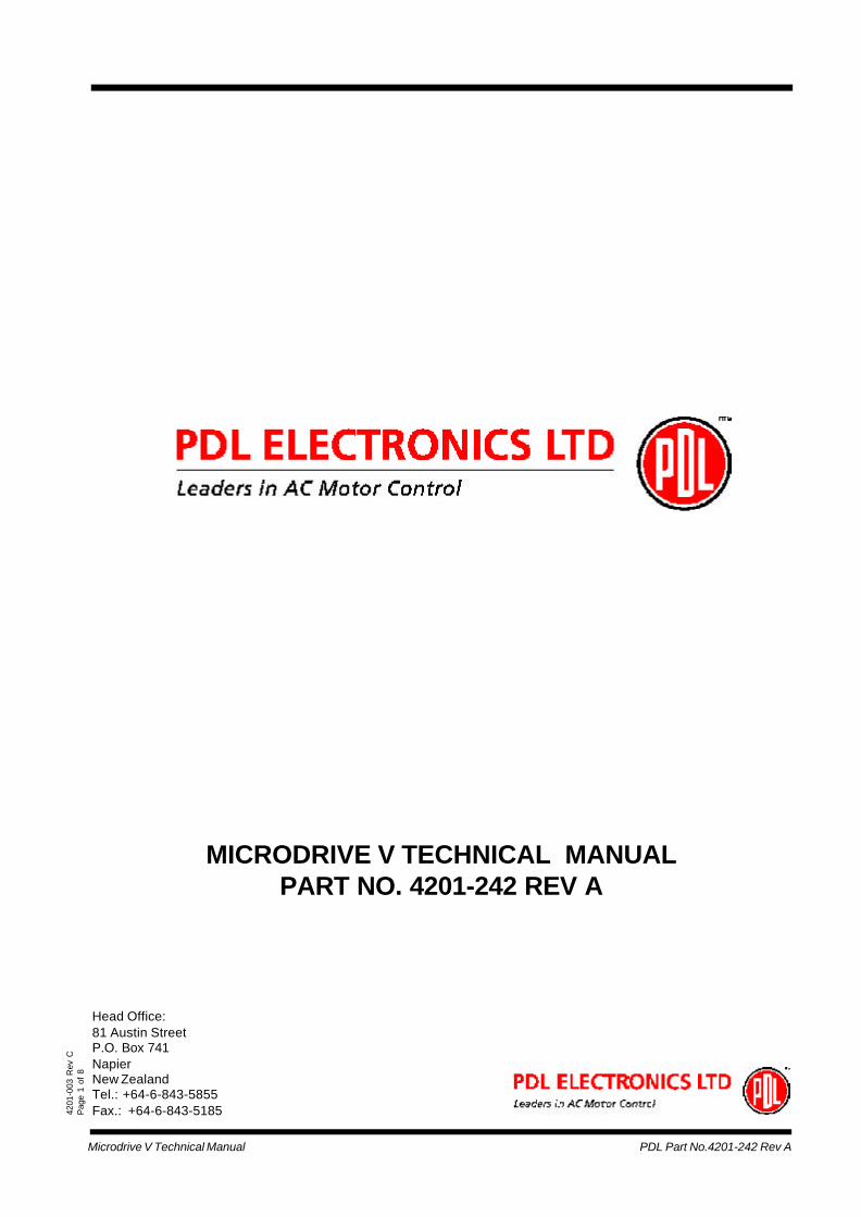
SYMBOLS USED
Caution, risk of electric shock ISO 3864, No. B.3.6
Caution (refer to accompanying documents) ISO 3864, No. B.3.1
Three-phase alternating current IEC 617-2, No. 02-02-06
________
__ __ __ Direct Current IEC 417, No. 5031
Protective Earth (PE) Terminal IEC 417 No. 5019
Earth (ground) Terminal IEC 417 No. 5017
Induction motor, three phase, squirrel cage IEC 617-2, No. 06-08-01
Microdrive V Technical Manual PDL Part No.4201-242 Rev A
9
1. SPECIFICATION
1.1 SCOPE
This specification describes the Microdrive V Series of AC Motor Speed Controller systems and presents theirelectrical and mechanical features.
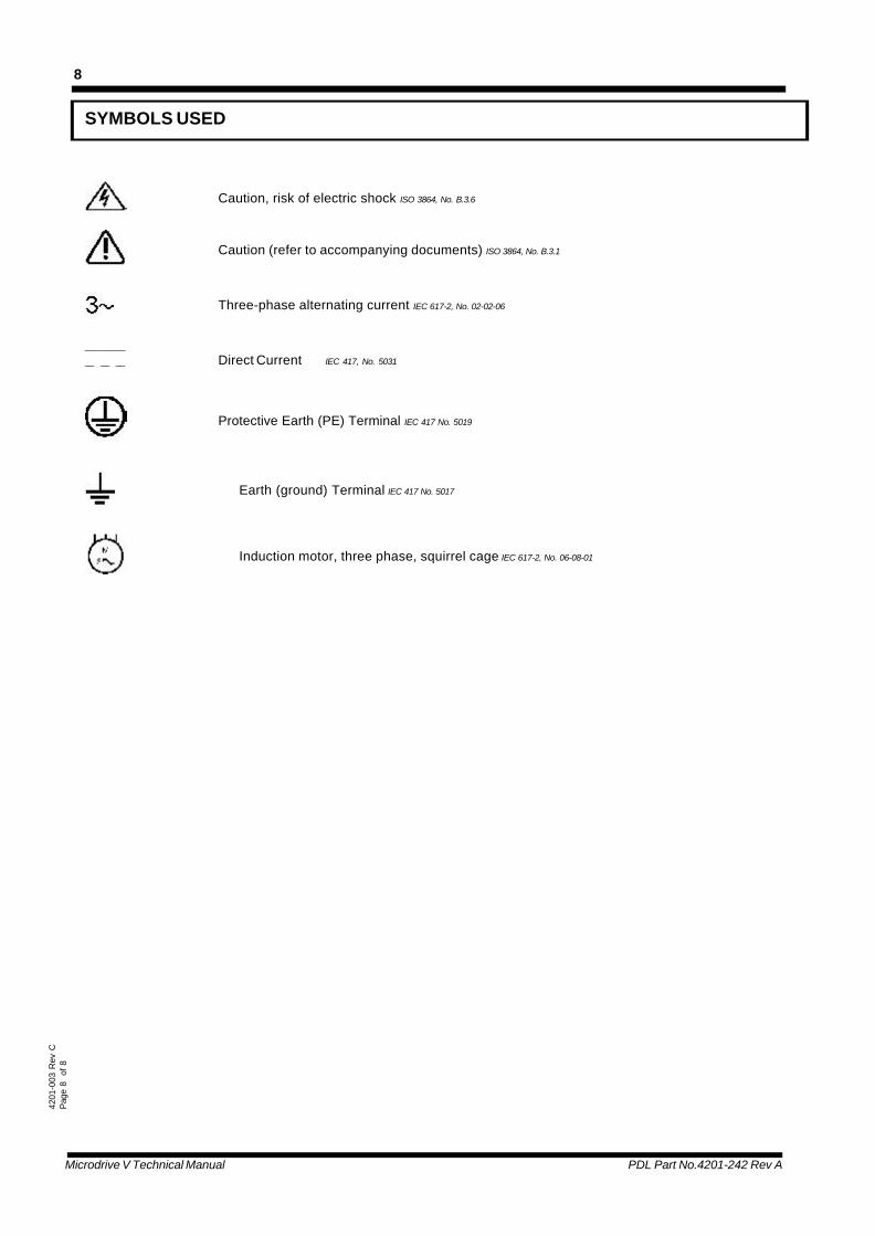
1.1.1 THE MICRODRIVE V SERIES SYSTEM
The Microdrive V Series is a modular high power range of low voltage AC Motor Speed Controllers which integratestrue sensorless vector control algorithms with the latest homogenous IGBT power and 32 bit RISC microprocessortechnologies.
The Microdrive V Series delivers outstanding motor control performance in an exceptionally small package size.
300:Fault Info
100:Interface 700:Special Function
Mains600:Inverter
4804-001 Rev A
500:Vector Control
200:Drive Controller
000:Menu Config
400:Motor
Inputline filter
Output500V/us
filter
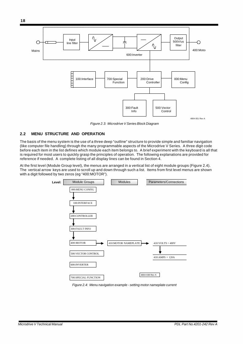
Figure 1.1: Microdrive V Series Block Diagram
Microdrive V Technical Manual PDL Part No.4201-242 Rev A
10
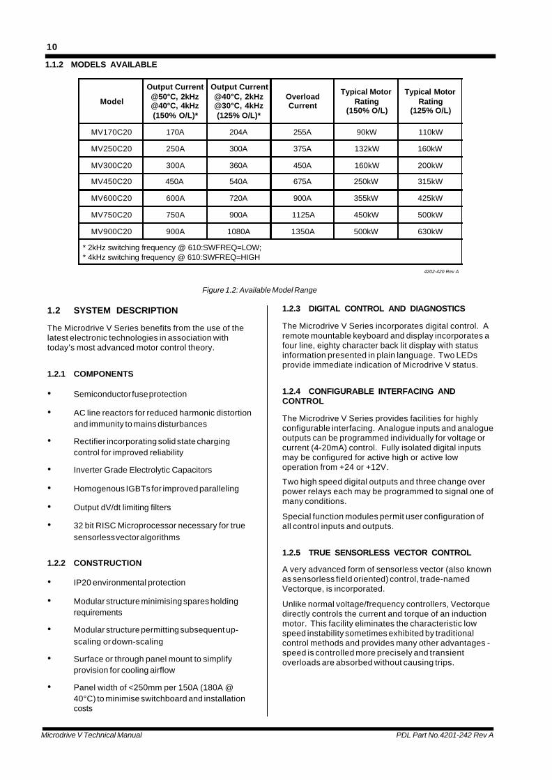
1.1.2 MODELS AVAILABLE
Model
Output Current@50°C, 2kHz@40°C, 4kHz(150% O/L)*
Output Current@40°C, 2kHz@30°C, 4kHz(125% O/L)*
OverloadCurrent
Typical MotorRating
(150% O/L)
Typical MotorRating
(125% O/L)
MV170C20 170A 204A 255A 90kW 110kW
MV250C20 250A 300A 375A 132kW 160kW
MV300C20 300A 360A 450A 160kW 200kW
MV450C20 450A 540A 675A 250kW 315kW
MV600C20 600A 720A 900A 355kW 425kW
MV750C20 750A 900A 1125A 450kW 500kW
MV900C20 900A 1080A 1350A 500kW 630kW
* 2kHz switching frequency @ 610:SWFREQ=LOW;* 4kHz switching frequency @ 610:SWFREQ=HIGH
4202-420 Rev A
Figure 1.2: Available Model Range
1.2 SYSTEM DESCRIPTION
The Microdrive V Series benefits from the use of thelatest electronic technologies in association withtoday’s most advanced motor control theory.
1.2.1 COMPONENTS
• Semiconductor fuse protection
• AC line reactors for reduced harmonic distortionand immunity to mains disturbances
• Rectifier incorporating solid state chargingcontrol for improved reliability
• Inverter Grade Electrolytic Capacitors
• Homogenous IGBTs for improved paralleling
• Output dV/dt limiting filters
• 32 bit RISC Microprocessor necessary for truesensorless vector algorithms
1.2.2 CONSTRUCTION
• IP20 environmental protection
• Modular structure minimising spares holdingrequirements
• Modular structure permitting subsequent up-scaling or down-scaling
• Surface or through panel mount to simplifyprovision for cooling airflow
• Panel width of <250mm per 150A (180A @40°C) to minimise switchboard and installationcosts
1.2.3 DIGITAL CONTROL AND DIAGNOSTICS
The Microdrive V Series incorporates digital control. Aremote mountable keyboard and display incorporates afour line, eighty character back lit display with statusinformation presented in plain language. Two LEDsprovide immediate indication of Microdrive V status.
1.2.4 CONFIGURABLE INTERFACING ANDCONTROL
The Microdrive V Series provides facilities for highlyconfigurable interfacing. Analogue inputs and analogueoutputs can be programmed individually for voltage orcurrent (4-20mA) control. Fully isolated digital inputsmay be configured for active high or active lowoperation from +24 or +12V.
Two high speed digital outputs and three change overpower relays each may be programmed to signal one ofmany conditions.
Special function modules permit user configuration ofall control inputs and outputs.
1.2.5 TRUE SENSORLESS VECTOR CONTROL
A very advanced form of sensorless vector (also knownas sensorless field oriented) control, trade-namedVectorque, is incorporated.
Unlike normal voltage/frequency controllers, Vectorquedirectly controls the current and torque of an inductionmotor. This facility eliminates the characteristic lowspeed instability sometimes exhibited by traditionalcontrol methods and provides many other advantages -speed is controlled more precisely and transientoverloads are absorbed without causing trips.

Microdrive V Technical Manual PDL Part No.4201-242 Rev A
11
The Vectorque true sensorless vector implementation inthe Microdrive V Series incorporates parameterinsensitive algorithms which avoid such problemsaltogether. Vectorque algorithms have only becomepractical through the use of a very powerful 32 bit RISCmicroprocessor.
An encoder feedback mode is provided for very highaccuracy speed control (closed loop).
1.2.6 MODULAR MECHANICAL DESIGN
The Microdrive V Series is unique in adopting amodular approach to mechanical construction. Thispermits ready change of size (add or remove modules)at a later date while minimising spares holdingrequirements since the same components are used inall models.
1.2.7 RADIO FREQUENCY SUPPRESSION
The Microdrive V Series includes radio interferencesuppression meeting the requirements of CISPR11(AS/NZS 2064:1997) level A, suitable for industrialenvironments. The Microdrive V Series carries C tickEMC certification recognised in Australia and NewZealand.
1.2.8 SPECIAL OPTIONS
The following special options are available:
• Dynamic Brake option - Can be interfaced withPDL B140 external dynamic brake controller.External power resistors are supplied to order.
• Regenerative / Unity Power Factor / SoftwareOption - Microdrive V Series may be suppliedtogether with a full four quadrant regenerativeinverter / rectifier for applications requiring muchbraking or very low harmonic distortion of thesupply.
• Harmonic Reduction Options - Several optionsexist for the reduction of harmonic distortion ofthe supply in high power applications - contactyour supplier. Refer to Section 11 - MainsHarmonic Reduction for details of 12 pulseoptions for the Microdrive V Series.
• Bearing Protection - AC drives may increase riskto motor bearings. Various solutions existincluding special bearing filters. Refer Section10- Bearing Filters - Protecting Motor Bearings.
1.3 GENERAL REQUIREMENTS
1.3.1 STANDARDS
AC Motor Control Products can dramatically improveyour process control, productivity and energy efficiency,but only if they are working correctly.
Which is why we at PDL Electronics go to great lengthsin our design and manufacturing, to ensure that ourproducts operate correctly first time, every time.
An extensive research and development investmentensures that this product is one of the most technicallyadvanced in the world, with built-in strength androbustness to suit your application and environment.
Our AS/NZS ISO 9001 certification gives you theconfidence of our international, independently certifiedQuality Assurance program. All staff are activelyinvolved in continuous improvement programs with acustomer focus.
The components that go into our products are selectedfrom the best in the world - and must pass our rigorousand demanding test program.
Finally, every new Microdrive V design is run through arigorous test program, including full load operation atabove rated temperature, under the most demandingload conditions.
Our dedication to quality makes the PDL Electronicsproduct, regardless of price, less expensive than othercontrollers in the long run.
1.3.2 COMPONENTS AND MATERIALS
All materials and parts comprising the Microdrive VSeries are new and in current production, and to ensuremaximum reliability, are used well within theparameters recommended by the supplier.
1.4 TECHNICAL DATA
1.4.1 INPUT
Nominal Input Voltage 380-480 VacPhases 3Voltage Tolerance -20/+5%Frequency 50/60Hz (DC option)Input Current ≤Output CurrentDisplacement Factor(COS∅) ≥0.95Distortion Factor ≤0.88InterruptionRide Through > 2 secondsPower connection (bottom entry) ≤MV600C20, single cable;
≤MV750C20, dual cablesMain fan supply 1∅ ,230Vac +/- 5%, <1A/module
1.4.2 OUTPUT
Output Voltage 0 - VinSlew rate-dV/dt ≤500V/µsOutput Frequency 0-100HzContinuous Current 0 - 100% ratedCurrent Overload 50°C/2kHz; 40°C/4kHz ratings -
150%, 30s (refer to Section2.1.4)
Re-rated 40°C/2kHz; 30°C/4kHz ratings -125%, 30s (refer to Section2.1.4)
Efficiency at rated load >97% @ 2kHz switching;> 96.5% @ 4kHz switching
Control Method True Sensorless Vector
Microdrive V Technical Manual PDL Part No.4201-242 Rev A
12
Power connection(bottom entry) ≤MV600C20, single cable;
≥MV750C20, dual cables
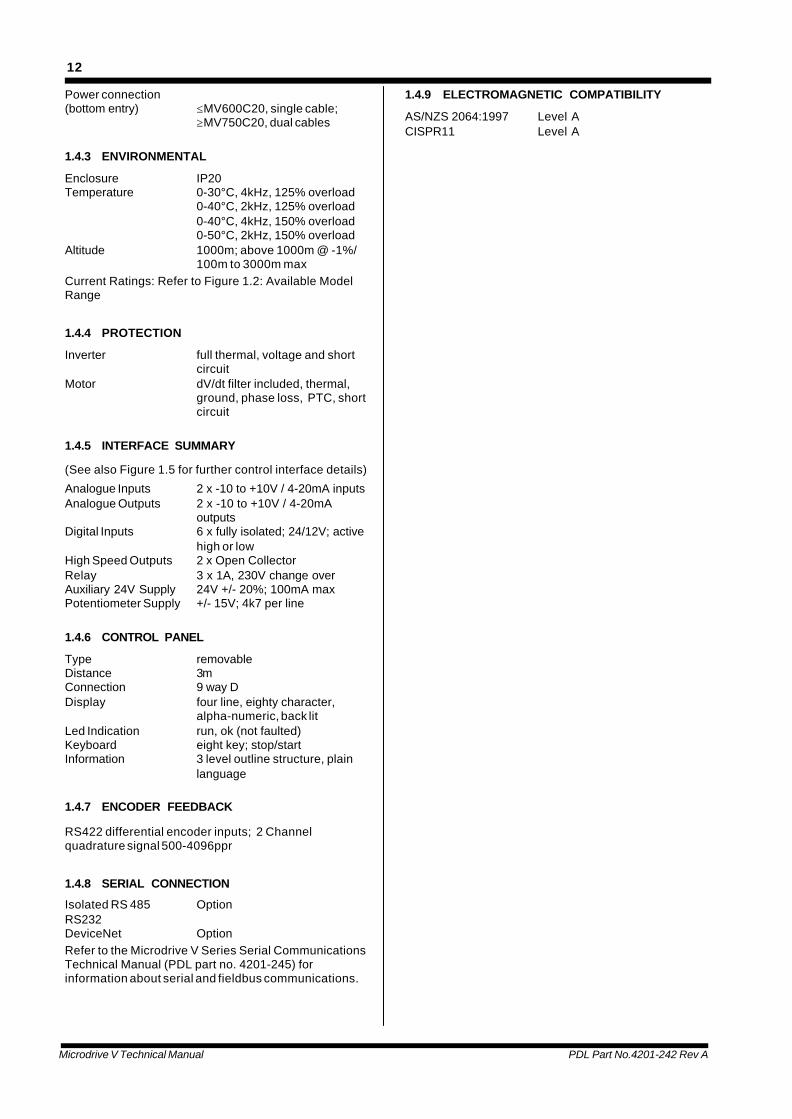
1.4.3 ENVIRONMENTAL
Enclosure IP20Temperature 0-30°C, 4kHz, 125% overload
0-40°C, 2kHz, 125% overload0-40°C, 4kHz, 150% overload0-50°C, 2kHz, 150% overload
Altitude 1000m; above 1000m @ -1%/100m to 3000m max
Current Ratings: Refer to Figure 1.2: Available ModelRange
1.4.4 PROTECTION
Inverter full thermal, voltage and shortcircuit
Motor dV/dt filter included, thermal,ground, phase loss, PTC, shortcircuit
1.4.5 INTERFACE SUMMARY
(See also Figure 1.5 for further control interface details)
Analogue Inputs 2 x -10 to +10V / 4-20mA inputsAnalogue Outputs 2 x -10 to +10V / 4-20mA
outputsDigital Inputs 6 x fully isolated; 24/12V; active
high or lowHigh Speed Outputs 2 x Open CollectorRelay 3 x 1A, 230V change overAuxiliary 24V Supply 24V +/- 20%; 100mA maxPotentiometer Supply +/- 15V; 4k7 per line
1.4.6 CONTROL PANEL
Type removableDistance 3mConnection 9 way DDisplay four line, eighty character,
alpha-numeric, back litLed Indication run, ok (not faulted)Keyboard eight key; stop/startInformation 3 level outline structure, plain
language
1.4.7 ENCODER FEEDBACK
RS422 differential encoder inputs; 2 Channelquadrature signal 500-4096ppr
1.4.8 SERIAL CONNECTION
Isolated RS 485 OptionRS232DeviceNet OptionRefer to the Microdrive V Series Serial CommunicationsTechnical Manual (PDL part no. 4201-245) forinformation about serial and fieldbus communications.
1.4.9 ELECTROMAGNETIC COMPATIBILITY
AS/NZS 2064:1997 Level ACISPR11 Level A
Microdrive V Technical Manual PDL Part No.4201-242 Rev A
13
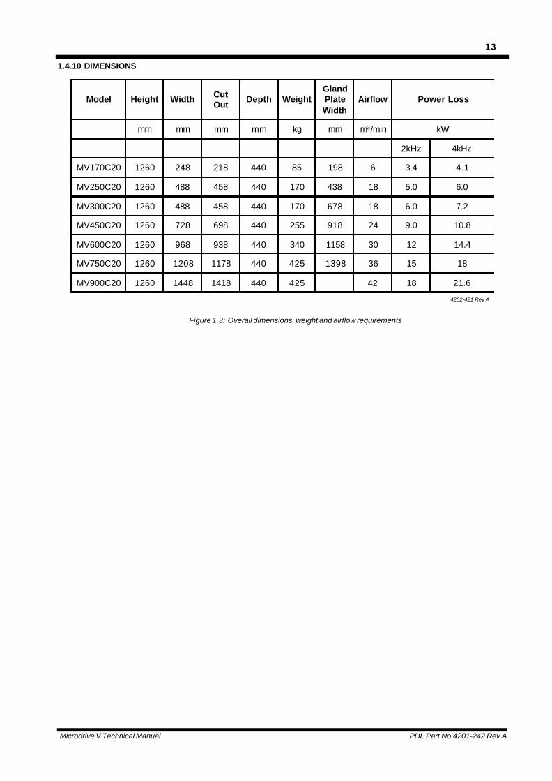
1.4.10 DIMENSIONS
Model Height Width CutOut
Depth WeightGlandPlateWidth
Airflow Power Loss
mm mm mm mm kg mm m3/min kW
2kHz 4kHz
MV170C20 1260 248 218 440 85 198 6 3.4 4.1
MV250C20 1260 488 458 440 170 438 18 5.0 6.0
MV300C20 1260 488 458 440 170 678 18 6.0 7.2
MV450C20 1260 728 698 440 255 918 24 9.0 10.8
MV600C20 1260 968 938 440 340 1158 30 12 14.4
MV750C20 1260 1208 1178 440 425 1398 36 15 18
MV900C20 1260 1448 1418 440 425 42 18 21.6
4202-421 Rev A
Figure 1.3: Overall dimensions, weight and airflow requirements
Microdrive V Technical Manual PDL Part No.4201-242 Rev A
14
Glandplate(Bottom)
Through-wall cut out
4804-002 Rev C
Optional through-wall mounting point
Internal cooling<30%
Outputs12
60 m
m
1180
mm
400m
m
330m
m
260m
m
Width Overall
455
mm
Inputs
1153
mm
Cut
Out
122 mm
Main fan
275 mm 165 mm
107mm
L1
L3
L2Airflow
92mm
175 mm
Auxiliaryfan
Bulk cooling>70%
Airflow
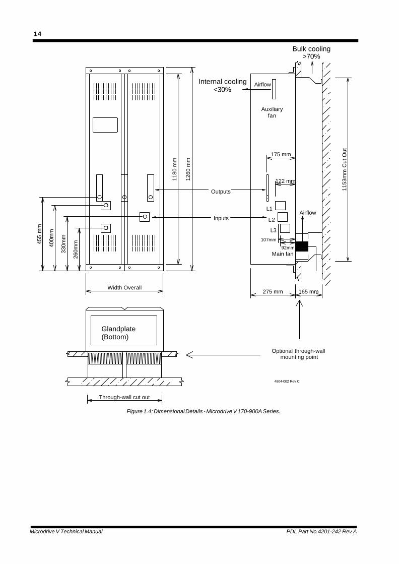
Figure 1.4: Dimensional Details - Microdrive V 170-900A Series.
Microdrive V Technical Manual PDL Part No.4201-242 Rev A
15
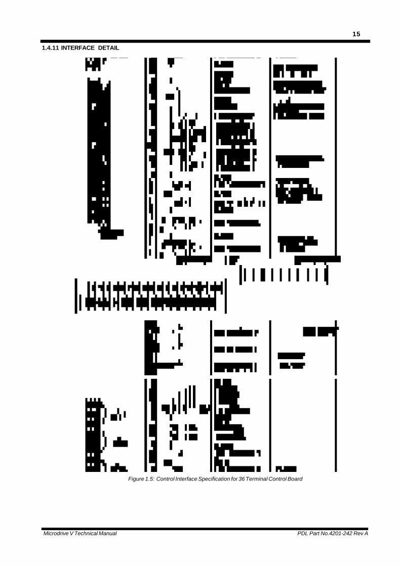
1.4.11 INTERFACE DETAIL
Figure 1.5: Control Interface Specification for 36 Terminal Control Board
Microdrive V Technical Manual PDL Part No.4201-242 Rev A
16
2. APPLICATION OF THE MICRODRIVE V SERIES
2.1 IMPORTANT MICRODRIVE V SERIESCONCEPTS
To achieve best results from the Microdrive V Series itis important that the user grasp the key issuesdiscussed in this section. Please read this sectioncarefully before proceeding - key concepts, if missedhere, will make understanding operation andcommissioning more difficult than necessary.
2.1.1 SENSORLESS VECTOR CONTROL
Sensorless vector control provides the ease ofconnection of simpler variable frequency drives (onlythree wires, no encoder) together with a performanceclose to encoder based vector drives.
Similar to DC Drive control, Vector control essentiallypermits the independent control of torque producingcurrent (equivalent to armature current) andmagnetising current (equivalent to field current) in astandard induction motor. Having achievedindependent control over these currents, highperformance speed and torque operation becomespossible. The Microdrive V permits such control at allspeeds, including near zero, without the need for anyseparate form of speed feedback sensor. Specialtechniques allow speed control at full torque throughzero speed.
From the users perspective, the type of control istransparent. The Microdrive V Series is simply used asa high performing motor speed and torque controller.
Vectorque sensorless vector control is applicable atfrequencies of 100Hz or less.
Note that Vectorque should not be applied to motorsrated less than 30% of the Microdrive V rating.
2.1.2 ENCODER VECTOR CONTROL
For applications requiring precise speed controlespecially near zero speed Vectorque closed loopVector control mode which utilises speed feedback isprovided. The rotor speed feedback is derived from ashaft mounted quadrature encoder.
This mode of control is recommended when very highspeed regulation is required and when the Microdrive Vis required to operate in torque control at or about zerospeed. Eg: winder/unwinders. This control isrecommended for high performance hoists andwinches.
As with sensorless control, closed loop vector control isapplicable to frequencies of 100Hz or less, and withsingle motors at ratings not less than 30% of theMicrodrive V rating.
2.1.3 V/HZ MODE
V/Hz mode is included only for special applications andshould not be applied in normal applications. Specialapplications include operation of motors much smallerthan the Microdrive V rating (ie. <30%), and operationof parallel motors of different types or with unbalancedloads. Some features of Vectorque are not available inV/Hz mode.
2.1.4 DUAL RATINGS
The Microdrive V Series is rated for both 40°C and50°C operation (at 2kHz switching frequency). At 40°Cthe Microdrive V Series is rated to provide 20%additional current over the 50°C rating. The overloadrating remains constant at both temperatures, providing50% above the continuous 50°C rating and 25% abovethe continuous 40°C rating.
The increased continuous rating at 40°C is often usefulin applications which do not require particularlydynamic operation or do not enter the overload region.Pumps and fans are typical of such applications,though many others exist.
2.1.5 PERCENTAGE VALUES ARE MOTORREFERENCED
Values, other than where given actual units (A, V etc)are generally shown as a percentage of the actualmotor rating that has been entered (percent of motorrated current, percent of motor rated torque etc). Notethat percent speed is given as a ratio of thesynchronous speed of the motor as Vectorque correctsfor slip errors.
2.1.6 KEYBOARD AND DISPLAY
The keyboard and display module is an intelligentcontroller connecting to the Microdrive V through astandard 9 way D connecting cable. The module maybe remotely mounted up to 3m with the standard cable.
The four line LCD display is largely programmable. Thetop line is fixed and shows status information about theMicrodrive V, including Local/Remote indication at theend of the line ie. “L” or “R”. The second, third andfourth lines can be programmed to show any of severalpreset meters (eg. SPEED, CURRENT, POWER) oreither of two user defined meters (see 030:LCDDISPLAY in Section 4 of the manual for details). Thefourth line doubles as the menu display line. Simplypress the down arrow key to access the menu system ifline four currently displays a meter.
Arrow keys, +, - and enter or cancel keys permitnavigation and adjustment of the menu system (SeeFigure 2.1). Stop and start push buttons permit localcontrol of the Microdrive V. They are always active,though subject to the status of external interfacecontrols.

Microdrive V Technical Manual PDL Part No.4201-242 Rev A
17
Stop (0) also provides a reset for any fault conditionswhich may be latched and displayed on the top line ofthe display.
2.1.7 MENU SCREENS AND CONTROLCONFIGURATION
The menu screens of the Microdrive V Series appear inline 4 of the display and are arranged using the blockoutline presented in Figure 2.3. Each of these blockscontains a group of modules and each module in turncontains parameters and configuration connections.
In summary, modules are grouped as:
000:Menu Config contains edit locks, keyboard refs.and meter selections.
100:Interface contains set up of all low voltageinputs and outputs
200:Controller contains all set up of the basicmotor controller
300:Fault Info contains fault history and autoreset controls
400:Motor contains set up of motor nameplateinformation etc
500:Vector Control contains vector control parameters
600:Inverter contains inverter user options andfactory calibrations
700:Special Functions contains a range of userselectable functions
Change Display Change Value Enter Cancel
RUN OK
'L'=Local (Keyboard)/'R'=Remote control
700 : Special Function
600 : Inverter
Status
000 : Menu Config
500 : Vector Control
300 : Fault Info
400 : Motor
100 : Interface
200 : Controller
Line 3 Selectable Meter
Line 4 Selectable Meter
Line 2 Selectable Meter
Description
Status LEDs
Start (Local)
Stop/Reset
4804-005 Rev A
RUN RCURRENT = 342.0ASPEED = 100.0%000:MENU CONFIG
Figure 2.1: Keyboard and Display
Two LEDs provide immediate status indication and the function of each is explained in the following table.
RUN LED DESCRIPTION OK LED DESCRIPTION
OFF Not running, no run command active. OFF Microdrive V control electronics notpowered.
ON Running, run command active. ON No faults have been detected.
FLASH
Temporarily stopped due to low mainsvoltage, run command active. Willrestart if mains voltage returns whilethe Microdrive V control electronics isstill powered from residual DC busvoltage.
FLASH
A fault exists which has tripped thedrive. The description field on the topline of the display will state which faulthas occurred.
4804-037 Rev A
Figure 2.2: Functions of the status LEDs on the keyboard.
Microdrive V Technical Manual PDL Part No.4201-242 Rev A
18
300:Fault Info
100:Interface 700:Special Function
Mains600:Inverter
4804-001 Rev A
500:Vector Control
200:Drive Controller
000:Menu Config
400:Motor
Inputline filter
Output500V/us
filter
Figure 2.3: Microdrive V Series Block Diagram
2.2 MENU STRUCTURE AND OPERATION
The basis of the menu system is the use of a three deep “outline” structure to provide simple and familiar navigation(like computer file handling) through the many programmable aspects of the Microdrive V Series. A three digit codebefore each item in the list defines which module each item belongs to. A brief experiment with the keyboard is all thatis required for most users to quickly grasp the principles of operation. The following explanations are provided forreference if needed. A complete listing of all display lines can be found in Section 4.
At the first level (Module Group level), the menus are arranged in a vertical list of eight module groups (Figure 2.4).The vertical arrow keys are used to scroll up and down through such a list. Items from first level menus are shownwith a digit followed by two zeros (eg “400:MOTOR”).
Level: Module Groups Modules Parameters/Connections
000:MENU CONFIG
500:VECTOR CONTROL
400:MOTOR
300:FAULT INFO
200:CONTROLLER
100:INTERFACE
700:SPECIAL FUNCTION
600:INVERTER
410:MOTOR NAMEPLATE 410:VOLTS = 400V
410:AMPS = 120A
4804-038 Rev A
Figure 2.4: Menu navigation example - setting motor nameplate current
Microdrive V Technical Manual PDL Part No.4201-242 Rev A
19
The second level (Module level) is entered by the useof the right arrow key. A list of modules is presentedand navigation through this list may be made again bythe use of the vertical arrows. Items in second levelmenus are located by the second digit (eg“410:MOTOR NAMEPLATE”). To return to higher levelmenus, push the left arrow key.
The third and final level (Data level) is selected byusing the right arrow key again, as the example inFigure 2.4 illustrates. Changes to parameters ormodule connections are performed at this level (levelsone and two provide headings only). Third leveldisplays also start with a three digit address in order toidentify which module they belong to and are followedby the label of the parameter or module connection.
2.3 MICRODRIVE V SERIES CONFIGURATIONOVERVIEW
The Microdrive V Series treats the variety of differentfunctions as separate “configuration modules”. Forexample, accessing the analogue output 1 module fromthe interface group in the menu permits theprogramming of current or voltage output, the definitionof output scaling, as well as the specification of thecontrolling source (eg. speed, torque etc). Eachmodule is presented in the same format and eachconsists of the following elements (listed in the menu inthis order):
Parameters ‘=’These are the settings oradjustments for the particularcontrols of the module eg. selectingNORMAL start mode for theMicrodrive V.
210:STRMDE=NORMAL
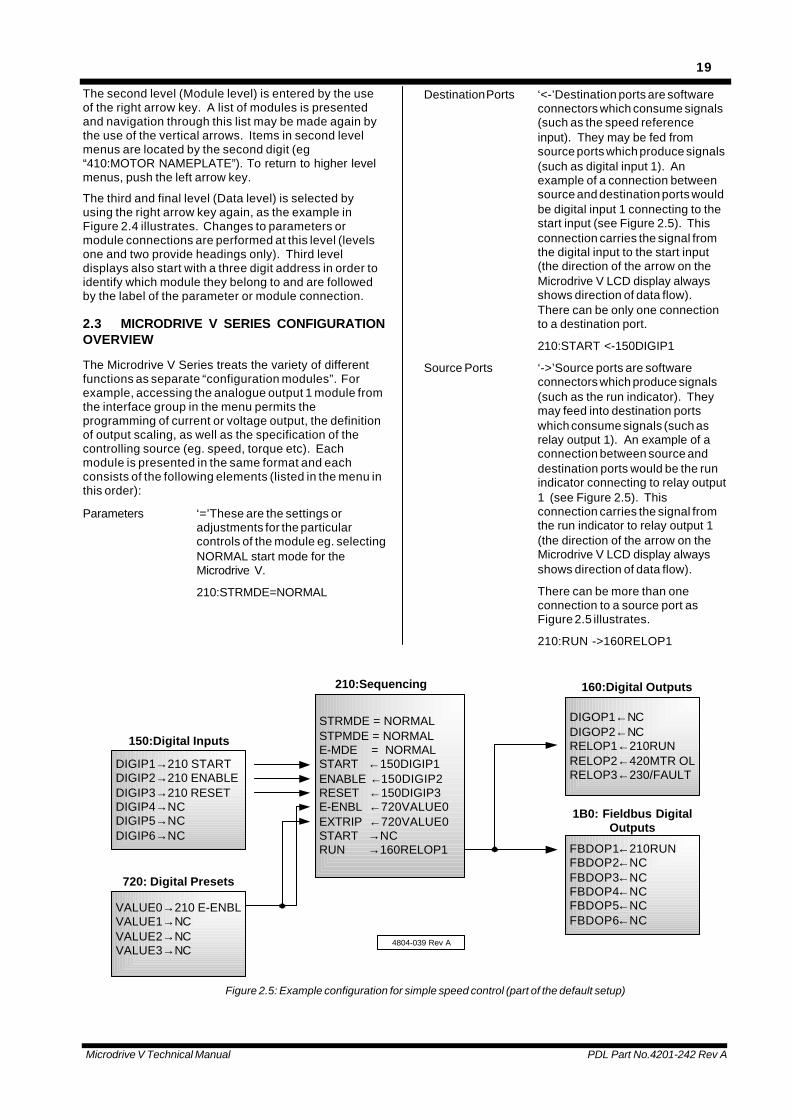
Destination Ports ‘<-’Destination ports are softwareconnectors which consume signals(such as the speed referenceinput). They may be fed fromsource ports which produce signals(such as digital input 1). Anexample of a connection betweensource and destination ports wouldbe digital input 1 connecting to thestart input (see Figure 2.5). Thisconnection carries the signal fromthe digital input to the start input(the direction of the arrow on theMicrodrive V LCD display alwaysshows direction of data flow).There can be only one connectionto a destination port.
210:START <-150DIGIP1
Source Ports ‘->’Source ports are softwareconnectors which produce signals(such as the run indicator). Theymay feed into destination portswhich consume signals (such asrelay output 1). An example of aconnection between source anddestination ports would be the runindicator connecting to relay output1 (see Figure 2.5). Thisconnection carries the signal fromthe run indicator to relay output 1(the direction of the arrow on theMicrodrive V LCD display alwaysshows direction of data flow).
There can be more than oneconnection to a source port asFigure 2.5 illustrates.
210:RUN ->160RELOP1
DIGIP1→210 STARTDIGIP2→210 ENABLEDIGIP3→210 RESETDIGIP4→NCDIGIP5→NCDIGIP6→NC
VALUE0→210 E-ENBLVALUE1→NCVALUE2→NCVALUE3→NC
STRMDE = NORMALSTPMDE = NORMALE-MDE = NORMALSTART ←150DIGIP1ENABLE ←150DIGIP2RESET ←150DIGIP3E-ENBL ←720VALUE0EXTRIP ←720VALUE0START →NCRUN →160RELOP1 FBDOP1←210RUN
FBDOP2←NCFBDOP3←NCFBDOP4←NCFBDOP5←NCFBDOP6←NC
DIGOP1←NCDIGOP2←NCRELOP1←210RUNRELOP2←420MTR OLRELOP3←230/FAULT
150:Digital Inputs
210:Sequencing
720: Digital Presets
160:Digital Outputs
1B0: Fieldbus DigitalOutputs
4804-039 Rev A
Figure 2.5: Example configuration for simple speed control (part of the default setup)
Microdrive V Technical Manual PDL Part No.4201-242 Rev A
20
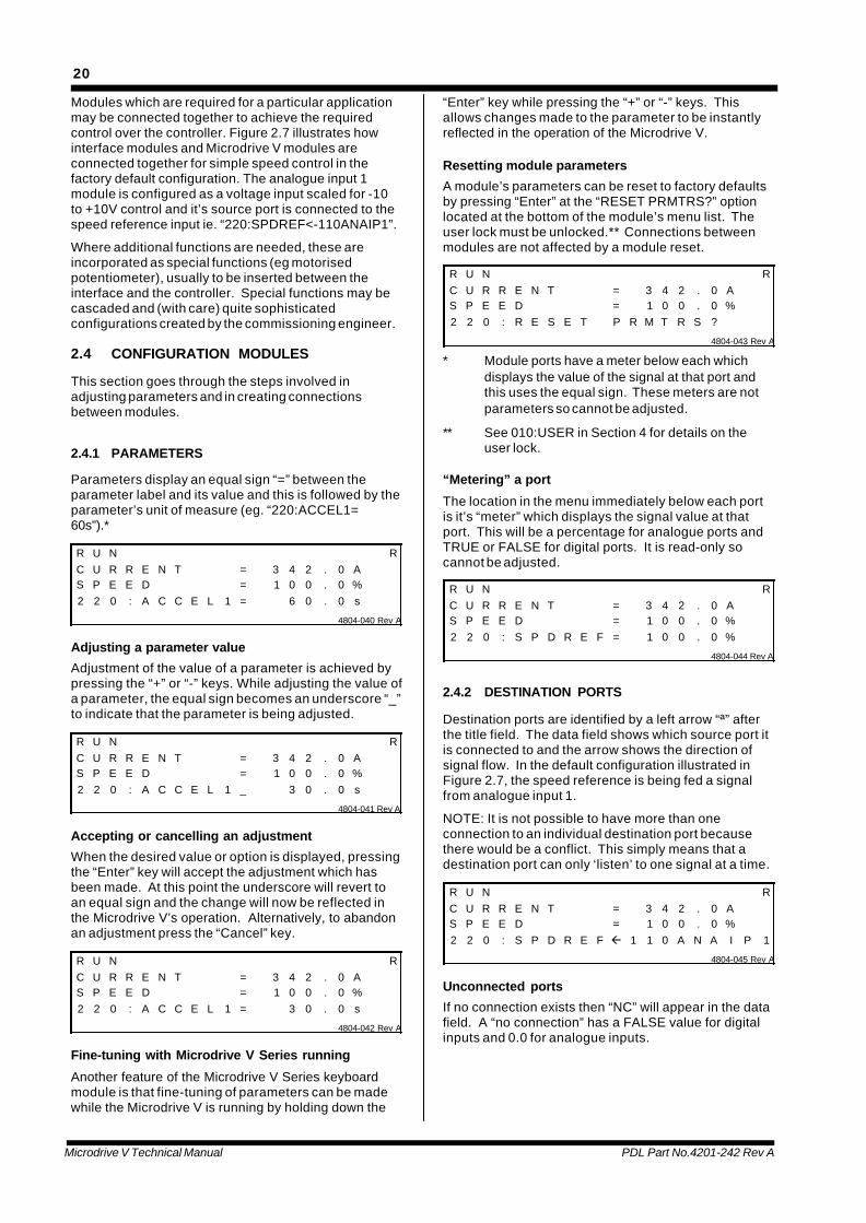
Modules which are required for a particular applicationmay be connected together to achieve the requiredcontrol over the controller. Figure 2.7 illustrates howinterface modules and Microdrive V modules areconnected together for simple speed control in thefactory default configuration. The analogue input 1module is configured as a voltage input scaled for -10to +10V control and it’s source port is connected to thespeed reference input ie. “220:SPDREF<-110ANAIP1”.
Where additional functions are needed, these areincorporated as special functions (eg motorisedpotentiometer), usually to be inserted between theinterface and the controller. Special functions may becascaded and (with care) quite sophisticatedconfigurations created by the commissioning engineer.
2.4 CONFIGURATION MODULES
This section goes through the steps involved inadjusting parameters and in creating connectionsbetween modules.
2.4.1 PARAMETERS
Parameters display an equal sign “=” between theparameter label and its value and this is followed by theparameter’s unit of measure (eg. “220:ACCEL1=60s”).*
R U N RC U R R E N T = 3 4 2 . 0 AS P E E D = 1 0 0 . 0 %2 2 0 : A C C E L 1 = 6 0 . 0 s
4804-040 Rev A
Adjusting a parameter value
Adjustment of the value of a parameter is achieved bypressing the “+” or “-” keys. While adjusting the value ofa parameter, the equal sign becomes an underscore “_”to indicate that the parameter is being adjusted.
R U N RC U R R E N T = 3 4 2 . 0 AS P E E D = 1 0 0 . 0 %2 2 0 : A C C E L 1 _ 3 0 . 0 s
4804-041 Rev A
Accepting or cancelling an adjustment
When the desired value or option is displayed, pressingthe “Enter” key will accept the adjustment which hasbeen made. At this point the underscore will revert toan equal sign and the change will now be reflected inthe Microdrive V’s operation. Alternatively, to abandonan adjustment press the “Cancel” key.
R U N RC U R R E N T = 3 4 2 . 0 AS P E E D = 1 0 0 . 0 %2 2 0 : A C C E L 1 = 3 0 . 0 s
4804-042 Rev A
Fine-tuning with Microdrive V Series running
Another feature of the Microdrive V Series keyboardmodule is that fine-tuning of parameters can be madewhile the Microdrive V is running by holding down the
“Enter” key while pressing the “+” or “-” keys. Thisallows changes made to the parameter to be instantlyreflected in the operation of the Microdrive V.
Resetting module parameters
A module’s parameters can be reset to factory defaultsby pressing “Enter” at the “RESET PRMTRS?” optionlocated at the bottom of the module’s menu list. Theuser lock must be unlocked.** Connections betweenmodules are not affected by a module reset.
R U N RC U R R E N T = 3 4 2 . 0 AS P E E D = 1 0 0 . 0 %2 2 0 : R E S E T P R M T R S ?
4804-043 Rev A
* Module ports have a meter below each whichdisplays the value of the signal at that port andthis uses the equal sign. These meters are notparameters so cannot be adjusted.
** See 010:USER in Section 4 for details on theuser lock.
“Metering” a port
The location in the menu immediately below each portis it’s “meter” which displays the signal value at thatport. This will be a percentage for analogue ports andTRUE or FALSE for digital ports. It is read-only socannot be adjusted.
R U N RC U R R E N T = 3 4 2 . 0 AS P E E D = 1 0 0 . 0 %2 2 0 : S P D R E F = 1 0 0 . 0 %
4804-044 Rev A
2.4.2 DESTINATION PORTS
Destination ports are identified by a left arrow “ª” afterthe title field. The data field shows which source port itis connected to and the arrow shows the direction ofsignal flow. In the default configuration illustrated inFigure 2.7, the speed reference is being fed a signalfrom analogue input 1.
NOTE: It is not possible to have more than oneconnection to an individual destination port becausethere would be a conflict. This simply means that adestination port can only ‘listen’ to one signal at a time.
R U N RC U R R E N T = 3 4 2 . 0 AS P E E D = 1 0 0 . 0 %2 2 0 : S P D R E F ß 1 1 0 A N A I P 1
4804-045 Rev A
Unconnected ports
If no connection exists then “NC” will appear in the datafield. A “no connection” has a FALSE value for digitalinputs and 0.0 for analogue inputs.
Microdrive V Technical Manual PDL Part No.4201-242 Rev A
21
O F F RC U R R E N T = 0 . 0 AS P E E D = 0 . 0 %2 2 0 : S P D R E F ß N C 4804-046 Rev A
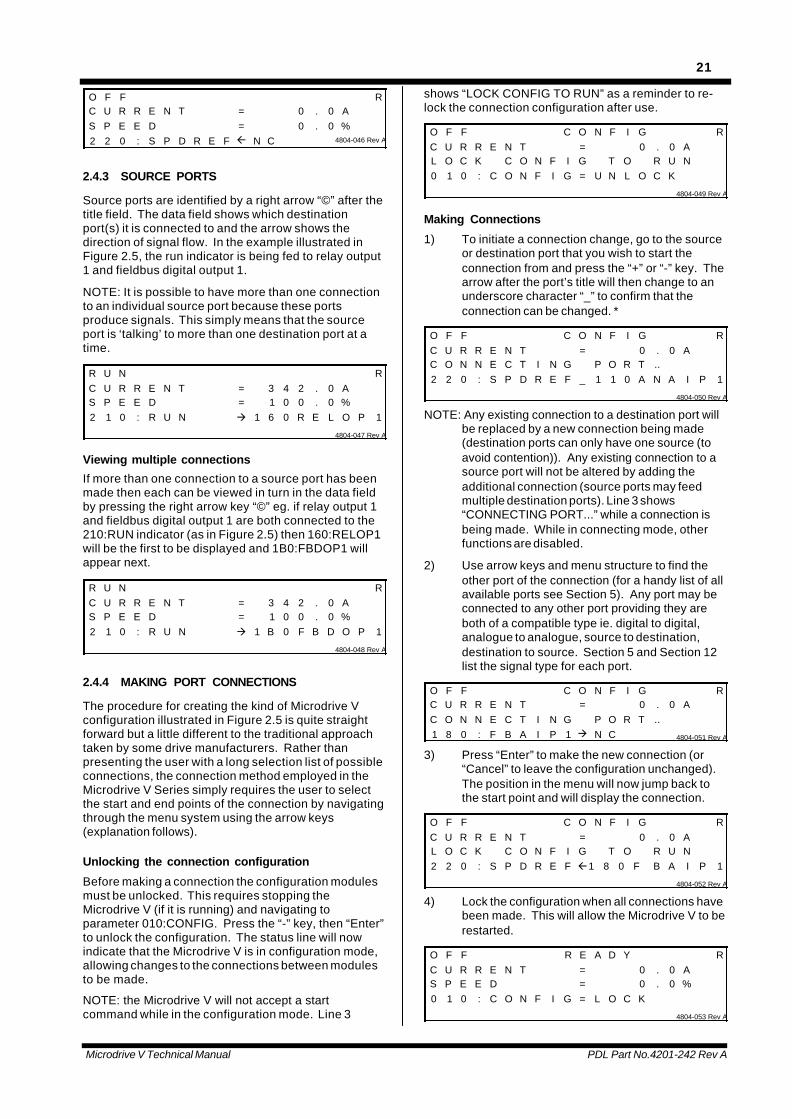
2.4.3 SOURCE PORTS
Source ports are identified by a right arrow “©” after thetitle field. The data field shows which destinationport(s) it is connected to and the arrow shows thedirection of signal flow. In the example illustrated inFigure 2.5, the run indicator is being fed to relay output1 and fieldbus digital output 1.
NOTE: It is possible to have more than one connectionto an individual source port because these portsproduce signals. This simply means that the sourceport is ‘talking’ to more than one destination port at atime.
R U N RC U R R E N T = 3 4 2 . 0 AS P E E D = 1 0 0 . 0 %2 1 0 : R U N à 1 6 0 R E L O P 1
4804-047 Rev A
Viewing multiple connections
If more than one connection to a source port has beenmade then each can be viewed in turn in the data fieldby pressing the right arrow key “©” eg. if relay output 1and fieldbus digital output 1 are both connected to the210:RUN indicator (as in Figure 2.5) then 160:RELOP1will be the first to be displayed and 1B0:FBDOP1 willappear next.
R U N RC U R R E N T = 3 4 2 . 0 AS P E E D = 1 0 0 . 0 %2 1 0 : R U N à 1 B 0 F B D O P 1
4804-048 Rev A
2.4.4 MAKING PORT CONNECTIONS
The procedure for creating the kind of Microdrive Vconfiguration illustrated in Figure 2.5 is quite straightforward but a little different to the traditional approachtaken by some drive manufacturers. Rather thanpresenting the user with a long selection list of possibleconnections, the connection method employed in theMicrodrive V Series simply requires the user to selectthe start and end points of the connection by navigatingthrough the menu system using the arrow keys(explanation follows).
Unlocking the connection configuration
Before making a connection the configuration modulesmust be unlocked. This requires stopping theMicrodrive V (if it is running) and navigating toparameter 010:CONFIG. Press the “-” key, then “Enter”to unlock the configuration. The status line will nowindicate that the Microdrive V is in configuration mode,allowing changes to the connections between modulesto be made.
NOTE: the Microdrive V will not accept a startcommand while in the configuration mode. Line 3
shows “LOCK CONFIG TO RUN” as a reminder to re-lock the connection configuration after use.
O F F C O N F I G RC U R R E N T = 0 . 0 AL O C K C O N F I G T O R U N0 1 0 : C O N F I G = U N L O C K
4804-049 Rev A
Making Connections
1) To initiate a connection change, go to the sourceor destination port that you wish to start theconnection from and press the “+” or “-” key. Thearrow after the port’s title will then change to anunderscore character “_” to confirm that theconnection can be changed. *
O F F C O N F I G RC U R R E N T = 0 . 0 AC O N N E C T I N G P O R T ..2 2 0 : S P D R E F _ 1 1 0 A N A I P 1
4804-050 Rev A
NOTE: Any existing connection to a destination port willbe replaced by a new connection being made(destination ports can only have one source (toavoid contention)). Any existing connection to asource port will not be altered by adding theadditional connection (source ports may feedmultiple destination ports). Line 3 shows“CONNECTING PORT...” while a connection isbeing made. While in connecting mode, otherfunctions are disabled.
2) Use arrow keys and menu structure to find theother port of the connection (for a handy list of allavailable ports see Section 5). Any port may beconnected to any other port providing they areboth of a compatible type ie. digital to digital,analogue to analogue, source to destination,destination to source. Section 5 and Section 12list the signal type for each port.
O F F C O N F I G RC U R R E N T = 0 . 0 AC O N N E C T I N G P O R T ..1 8 0 : F B A I P 1 à N C 4804-051 Rev A
3) Press “Enter” to make the new connection (or“Cancel” to leave the configuration unchanged).The position in the menu will now jump back tothe start point and will display the connection.
O F F C O N F I G RC U R R E N T = 0 . 0 AL O C K C O N F I G T O R U N2 2 0 : S P D R E F ß1 8 0 F B A I P 1
4804-052 Rev A
4) Lock the configuration when all connections havebeen made. This will allow the Microdrive V to berestarted.
O F F R E A D Y RC U R R E N T = 0 . 0 AS P E E D = 0 . 0 %0 1 0 : C O N F I G = L O C K
4804-053 Rev A

Microdrive V Technical Manual PDL Part No.4201-242 Rev A
22
Disconnecting Connections
To disconnect a connection to a destination port, pressthe “+” or “-” key followed directly by the “ENTER” key.“NC” (No Connection) will appear in the data field. A“no connection” inputs a FALSE value for digitaldestination ports and 0.0% for analogue destinationports.
O F F C O N F I G RC U R R E N T = 0 . 0 AL O C K C O N F I G T O R U N2 2 0 : S P D R E F à N C 4804-054 Rev A
Connections cannot be disconnected at a source port -the relevant destination port must be selected and thedisconnection made from this point.
2.5 DEFAULT CONFIGURATION
2.5.1 DESCRIPTION
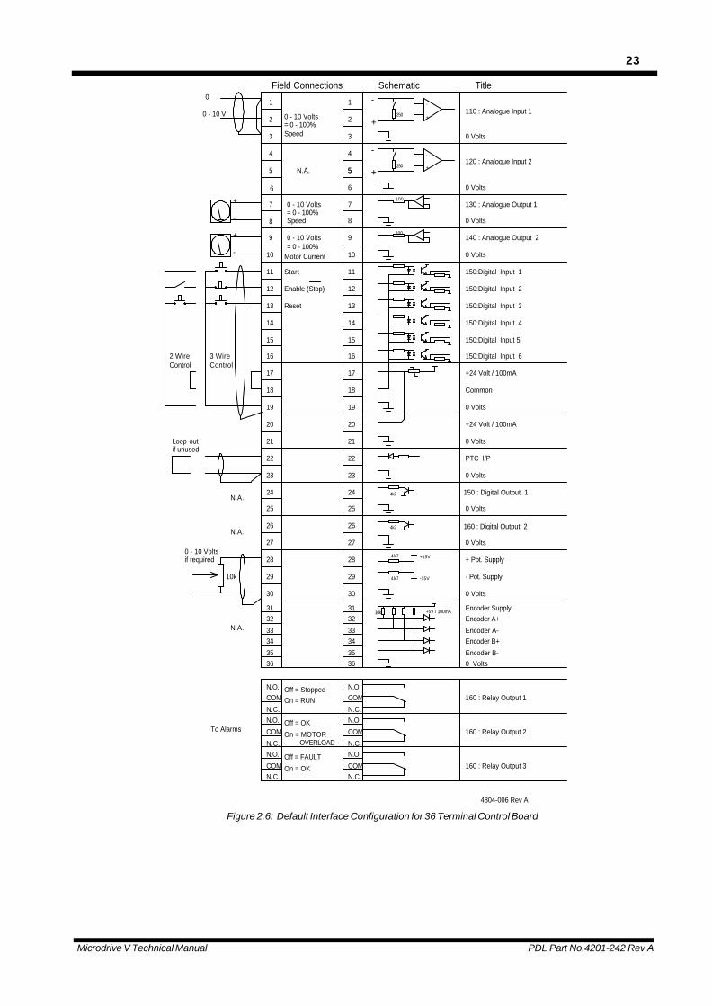
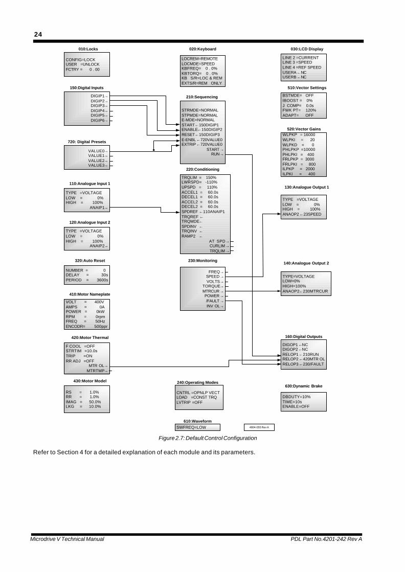
The factory default configuration of the Microdrive VSeries is summarised in the following two figures. Thedefault control configuration provides analogue voltage(-10 to +10V) speed control with three-wire start/stop/reset and analogue output (-10 to +10V) of speed andmotor current.
Microdrive V Technical Manual PDL Part No.4201-242 Rev A
23
22 22 PTC I/P
10k
COMCOM
To AlarmsOn = MOTOR OVERLOAD
N.O.
COM
N.C.
COMN.C.
N.O.
N.C.On = RUN
Off = OKCOM
COM
N.O.
N.C.
N.C.
N.O.
N.C.
Off = FAULT
On = OK
0 - 10 Voltsif required
10k 29 29
N.A.
Off = StoppedN.O.
30
3132
3334
3536
31
3536
N.O.
3433
32
30
2323
N.A.
N.A.
26
27
28
24
25
26
27
28
24
25
160 : Relay Output 1
160 : Relay Output 2
160 : Relay Output 3
4804-006 Rev A
4k7 - Pot. Supply-15V
Encoder SupplyEncoder A+
Encoder A-Encoder B+
Encoder B-
+5V / 100mA
0 Volts
0 Volts
4k7
4k7
4k7
0 Volts
150 : Digital Output 1
160 : Digital Output 2
+ Pot. Supply+15V
0 Volts
0 Volts
Schematic
Control
if unusedLoop out
2 WireControl3 Wire
20
21
18
19
17
16
21
20
18
19
17
16
15 15
+
- 10Motor Current10
Enable (Stop)
14
13
11
12
Reset
Start
14
13
11
12
0 - 10 Volts9 9= 0 - 100%
0 - 10 V
0
-
+
= 0 - 100%0 - 10 Volts
Speed
6
7
8
4
5 N.A.
0 - 10 Volts= 0 - 100%Speed3
2
8
7
6
55
4
3
2 +
+
-
Field Connections
1 1 -
+24 Volt / 100mA
+24 Volt / 100mA
Common
150:Digital Input 6
0 Volts
0 Volts
150:Digital Input 5
100
0 Volts
150:Digital Input 4
150:Digital Input 3
150:Digital Input 2
150:Digital Input 1
140 : Analogue Output 2
110 : Analogue Input 1
100
250
250
130 : Analogue Output 1
120 : Analogue Input 2+
-
0 Volts
0 Volts
0 Volts
+
-
Title
Figure 2.6: Default Interface Configuration for 36 Terminal Control Board
Microdrive V Technical Manual PDL Part No.4201-242 Rev A
24
CONFIG=LOCKUSER =UNLOCKFCTRY = 0 . 00
VALUE0→VALUE1→VALUE2→VALUE3→
LOCREM=REMOTELOCMDE=SPEEDKBFREQ= 0 . 0%KBTORQ= 0 . 0%KB S/R=LOC & REMEXTS/R=REM ONLY
DBDUTY=10%TIME=10sENABLE=OFF
DIGOP1←NCDIGOP2←NCRELOP1←210RUNRELOP2←420MTR OLRELOP3←230/FAULT
010:Locks 020:Keyboard
720: Digital Presets
160:Digital Outputs
630:Dynamic Brake
DIGIP1→DIGIP2→DIGIP3→DIGIP4→DIGIP5→DIGIP6→
150:Digital Inputs
STRMDE=NORMALSTPMDE=NORMALE-MDE=NORMALSTART←150DIGIP1ENABLE←150DIGIP2RESET←150DIGIP3E-ENBL←720VALUE0EXTRIP←720VALUE0
START→RUN→
210:Sequencing
LINE 2 =CURRENTLINE 3 =SPEEDLINE 4 =REF SPEEDUSERA←NCUSERB←NC
030:LCD Display
BSTMDE= OFFIBOOST = 0%J COMP= 0.0sFWK PT= 120%ADAPT= OFF
510:Vector Settings
TYPE =VOLTAGELOW = 0%HIGH = 100%
ANAIP1→
110:Analogue Input 1
TYPE =VOLTAGELOW = 0%HIGH = 100%
ANAIP2→
120:Analogue Input 2
NUMBER = 0DELAY = 30sPERIOD = 3600s
320:Auto Reset
VOLT = 400VAMPS = 0APOWER = 0kWRPM = 0rpmFREQ = 50HzENCODR= 500ppr
410:Motor Nameplate
F COOL =OFFSTRTIM =10.0sTRIP =ONRR ADJ =OFF
MTR OL→MTRTMP→
420:Motor Thermal
RS = 1.0%RR = 1.0%IMAG = 50.0%LKG = 10.0%
430:Motor Model
TRQLIM = 150%LWRSPD= -110%UPSPD = 110%ACCEL1 = 60.0sDECEL1 = 60.0sACCEL2 = 60.0sDECEL2 = 60.0sSPDREF ←110ANAIP1TRQREF ←TRQMDE←SPDINV ←TRQINV ←RAMP2 ←
AT SPD→CURLIM→TRQLIM→
220:Conditioning
FREQ→SPEED→VOLTS→
TORQUE→MTRCUR→POWER→/FAULT→INV OL→
230:Monitoring
SWFREQ=LOW610:Waveform
CNTRL =OPNLP VECTLOAD =CONST TRQLVTRIP =OFF
240:Operating Modes
WLPKP = 16000WLPKI = 20WLPKD = 0PHLPKP =10000PHLPKI = 400FRLPKP = 3000FRLPKI = 800ILPKP = 2000ILPKI = 400
520:Vector Gains
TYPE=VOLTAGELOW=0%HIGH=100%ANAOP2←230MTRCUR
140:Analogue Output 2
TYPE =VOLTAGELOW = 0%HIGH = 100%ANAOP2←23SPEED
130:Analogue Output 1
4804-055 Rev A
Figure 2.7: Default Control Configuration
Refer to Section 4 for a detailed explanation of each module and its parameters.

Microdrive V Technical Manual PDL Part No.4201-242 Rev A
25
2.6 MOTOR DERATING
Figure 2.8 shows recommended derating of motors (without special cooling provision) connected to the Microdrive VSeries. At low speeds torque derating is required due to reduced efficiency of motor cooling fans. Above rated speedinsufficient fluxing voltage is available, and available torque per ampere drops inversely.
Continuous running derating factor forinduction motors supplied from aMicrodrive V
Series Drive
0
20
40
60
80
100
120
0 20 40 60 80 100 120 140 160 180 200
Speed (%)
Torq
ue D
erat
ing
Fact
or (%
)
4804-056 Rev A
Figure 2.8: Microdrive V Series Typical Motor Derating Curve
Microdrive V Technical Manual PDL Part No.4201-242 Rev A
26
3. INSTALLATION AND COMMISSIONING
3.1 MECHANICAL INSTALLATION
3.1.1 MOUNTING
The Microdrive V Series is supplied with brackets forsurface mounting. The same mounting brackets can berepositioned centrally to permit through wall mounting.Through wall mounting permits the main air stream tobe placed external to an electrical switchboard,eliminating the need for additional switchboard cooling.Refer to Figure 1.4 for dimensions.
3.1.2 COOLING
Cooling airflows in the Microdrive V Series must not beimpeded. If mounting internally in a switchboard,sufficient airflow must be provided (See Section 1.4.10for power loss and airflow information).
Two methods are available to the installer .
* Through wall mounting - if through wall mounted,care must be taken to allow for remaining lossesof about 30% in the switchboard itself. Additionalair flow exhausting from the top of theswitchboard is usually required.
* The Microdrive V fan has sufficient power to drawand exhaust its cooling air requirements as longas ducting is not restrictive. This can eliminatethe need for additional air supply. Make provisionfor air inlet into the switchboard and duct exhaustair outside the switchboard away from the inlet.
The main cooling fans require a separate 230Vacpower supply to be provided to the main fan terminals.Fan load current does not exceed 1A per Microdrive VSeries module.
In all cases check that the necessary high volume of airexhausts at the top of each Microdrive V Series moduleand cooling is adequate during commissioning.
3.2 ELECTRICAL INSTALLATION
3.2.1 EMC (ELECTROMAGNETIC COMPATIBILITY)
Electromagnetic compatibility refers to the safe andreliable operation of both the Microdrive V Series andother equipment sharing the same electromagneticoperating environment.
To assure EMC and radio interference levels areachieved, it is important that installation is carried outexactly according to the instructions of this manual.
3.2.2 CONTROL (SIGNAL) CABLING
Normal control cabling practice applies. Controlsshould be screened and earthed at the Microdrive Vend only. Control cable should be run at least 300mmaway from power cables (especially power outputcables from AC Drives) and, where necessary, shouldcross power cables only at right angles.
3.2.3 EARTHING
The Microdrive V Series must be solidly bonded topower supply earth before energising. Potentially highleakage currents necessitate a permanent connectionbetween Microdrive V chassis and mains earth.
Mains power earth must be connected to the PEterminal.
Motor earth must be made directly from motor chassisto Microdrive V motor earth terminal (ME) - preferablyvia the motor cable screen bonded at both ends.Where maximum radio suppression is required,screened three core cables must be used and the cablescreen must be well bonded to the motor frame andconnected directly to the Microdrive V Series MEterminal - it must not be connected elsewhere en-route.
3.2.4 POWER CABLING
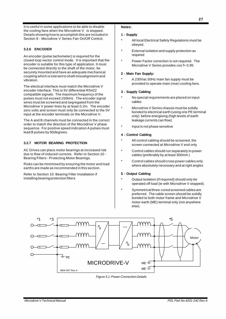
Power Cabling requirements are summarised in Figure3.1: Power Connection Details.
Microdrive V Series models up to MV600C20 aredesigned for connection with single input and outputcables. Models MV750C20 and above have dualtermination points designed for connection to paralleledcable runs.
Cable entry is made through a gland plate at the bottomof the Microdrive V.
The Microdrive V Series has very effective RFI filteringbuilt in as standard.
In sensitive applications, and where output cables runwith other output cables or near mains supply cables, ascreened three-core motor cable is recommended.Such a cable must be solidly and directly bonded toboth the motor and Microdrive V Series chassis to beeffective.
3.2.5 MAIN 230VAC FAN SUPPLY
Microdrive V Series require a 230Vac +/- 5% 50Hzsupply (<1A per module) to operate main (rear) coolingfans. It is most important to ensure that rear coolingfans operate and can provide the necessary bulk air forproper cooling when installing and commissioning theMicrodrive.
Microdrive V Technical Manual PDL Part No.4201-242 Rev A
27
It is useful in some applications to be able to disablethe cooling fans when the Microdrive V is stopped.Details showing how to accomplish this are included inSection 8 - Microdrive V Series Fan On/Off Control.
3.2.6 ENCODER
An encoder (pulse tachometer) is required for theclosed loop vector control mode. It is important that theencoder is suitable for this type of application. It mustbe connected directly to the shaft of the motor, besecurely mounted and have an adequate mechanicalcoupling which is tolerant to shaft missalignment andvibration.
The electical interface must match the Microdrive Vencoder interface. This is 5V differential RS422compatible signals. The maximum frequency of thepulses must not exceed 150kHz. The encoder signalwires must be screened and segregated from theMicrodrive V power lines by at least 0.2m. The encoderzero volts and screen must only be connected to the 0Vinput at the encoder terminals on the Microdrive V.
The A and B channels must be connected in the correctorder to match the direction of the Microdrive V phasesequence. For positive speed indication A pulses mustlead B pulses by 90degrees.
3.2.7 MOTOR BEARING PROTECTION
AC Drives can place motor bearings at increased riskdue to flow of induced currents. Refer to Section 10 -Bearing Filters - Protecting Motor Bearings.
Risks can be minimised by ensuring the motor and loadearths are made as recommended in this section.
Refer to Section 10: Bearing Filter Installation ifinstalling bearing protection filters
Notes:
1 - Supply
* All local Electrical Safety Regulations must beobeyed.
* External isolation and supply protection asrequired
* Power Factor correction is not required. TheMicrodrive V Series provides cos f> 0.95.
2 - Main Fan Supply:
* A 230Vac 50Hz main fan supply must beprovided to operate main (rear) cooling fans.
3 - Supply Cabling
* No special requirements are placed on inputcables
* Microdrive V Series chassis must be solidlybonded to electrical earth (using one PE terminalonly) before energising (high levels of earthleakage currents can flow)
* Input is not phase sensitive
4 - Control Cabling
* All control cabling should be screened, thescreen connected at Microdrive V end only
* Control cables should run separately to powercables (preferably by at least 300mm )
* Control cables should cross power cables onlywhere absolutely necessary and at right angles
5 - Output Cabling
* Output isolation (if required) should only beoperated off load (ie with Microdrive V stopped).
* Symmetrical three-cored screened cables arepreferred. The cable screen should be solidlybonded to both motor frame and Microdrive Vmotor earth (ME) terminal only (not anywhereelse).
*3*1
MICRODRIVE-VPE
4804-007 Rev A
Motor
ME
ME
*5
Figure 3.1: Power Connection Details
Microdrive V Technical Manual PDL Part No.4201-242 Rev A
28
* If motor and load frames are electrically isolated,but electrically connected via shafts, install anisolated coupling in the shafts or bond motor andload using a wide flat (25mm) conductor such asbraid or copper foil using the most directconnecting route (don’t rely on common earthconnections back to switch boards).
* Some regulations may require an earth to be runin addition to using the cable screen. If requiredthis earth should run externally to the screenedcable.
* Power factor correction capacitors must not beconnected to Microdrive V Series output.
* If facility for electrical bypass of the motor tomains is required, the Microdrive V Series outputmust be isolated from the motor first (theMicrodrive V Series output must never beconnected to mains supply).
3.3 COMMISSIONING
For convenience Section 6 presents a suggestedcommissioning schedule.
3.3.1 SAFETY WARNING
- It is the installer’s responsibility to ensure theconfiguration and installation of the Microdrive VSeries meets the requirements of any sitespecific, local and national electrical regulations.
- The Microdrive V Series operates from HIGHVOLTAGE, HIGH ENERGY ELECTRICALSUPPLIES. Stored charge is present after switchoff.
- Due to the high leakage currents inherent to ACdrives, earth connection of both the motor andthe Microdrive V Series is essential beforeconnection to the supply. The Microdrive VSeries must be permanently connected to thesupply.
- For safety reasons, normal operation of theMicrodrive V Series requires front covers/doors tobe in place and secured closed.
- Do not attempt to isolate the motor while theMicrodrive V Series is running.
- Some parameter settings may cause theMicrodrive V Series to start automatically afterpower failure.
- Motor overspeed operation may be limited bymechanical constraints.
3.3.2 INSTALLATION INSPECTION
* Mechanical
Check that the mechanical mounting of the MicrodriveV is adequate.
* Thermal
Check that airflow paths are free and are able to carrythe required air flow (refer to Figure 1.3: Overalldimensions, weight and airflow requirements). Checkthat thermal design caters for potential heat loss(approx. 70% of motor load at the rear cooling path,30% (max) at front cooling path - see Figure 1.4).
* Electrical
Check the electrical installation of cables, crimps andlugs making sure that sizing is appropriate. Check atthe Microdrive V input, output and motor terminals.
Check that the main fan supply is connected.
Check that the earthing has been carried out correctlyaccording to the instructions in Figure 3.1.
Ensure that no loose material, swarf or moisture hasentered the Microdrive V.
3.3.3 ENERGISING THE MICRODRIVE V
Warning: The Microdrive V Series is powered fromhigh energy electrical supplies. Suitably qualified staffmust inspect and approve the installation prior topowering the Microdrive V. Safety is the responsibilityof the commissioning engineer. Safety should never becompromised.
Ensure mechanical safety by
- making sure all staff are clear of connectedmachinery
- if necessary, decoupling the motor shaft
- if possible, isolating the motor while programmingthe Microdrive V
- open the PTC circuit - this will always prevent theMicrodrive V starting, regardless of set up.
Turn the power on. The display should illuminate.Internal fans should exhaust air at the top front of theMicrodrive V, while main (rear) fans should exhaustbulk cooling air at the top rear of each module (check).
If the PTC circuit has been opened the display willindicate a motor PTC fault.
3.3.4 USING THE MICRODRIVE V SERIES IN ITS“STANDARD CONFIGURATION”
When received ex factory, the Microdrive V Series hasbeen fully reset to default condition (see Section 2.5).Often the Microdrive V can be used in thisconfiguration, or with only a few simple adjustments.For more information about any parameter or settingrefer to the relevant screen detail in Section 4.
The standard configuration sets the Microdrive V upwith a very standard set of inputs and outputs (refer toFigure 2.6).
The standard configuration is set up for voltage inputsand outputs (+/- 10V = -100 to +100% which means 0to +10V = 0 to 100%). If current (4-20mA) input oroutput is required, the analogue channels can bereprogrammed using the appropriate interface
Microdrive V Technical Manual PDL Part No.4201-242 Rev A
29
programming screens (100:INTERFACE).
Standard parameters are preset:-
acceleration 220:ACCEL1= 60.0 seconds
deceleration 220:DECEL1= 60.0 seconds
upper speed limit 220:UPSPD = 110% of ratedmotor speed
lower speed limit 220:LWRSPD= -110% of ratedmotor speed
If negative speed (ie. reverse) is not desired, it is agood idea to set 220:LWRSPD to 0%.
Normal start (ramp from zero speed) and stop (ramp tozero speed) are set.
For those familiar with earlier generation drives andused to having to set up “boost” controls, note thatnormal Vectorque control does not need boostadjustment.
A current boost is available in a special boost mode. Inall other modes this boost control has no function.
Motor nameplate (410:MOTOR NAMEPLATE) detailsmust be entered correctly to ensure motor protectionand provide correct operation. Following entry of themotor parameters, the option is given to“410:CALCULATE MODEL?”. It is important to acceptthis option (press the Enter key) at this point to havethe motor model parameters automatically calculatedfrom the nameplate data entered. Check that theautomatically calculated values are sensible vs Set upguide for motor model parameters (Section 4).
For standard motors and applications, these are usuallythe only parameters which must be set prior tooperation of the Microdrive V.
Warning: Vectorque must not be used with motorsrated at less than 1/3 of the Microdrive V current rating(for test purposes with small motors V/Hz mode can beused - set 240:CNTRL =V/Hz). Attempts to trial verysmall motors in Vectorque mode will result in excessivemotor current and damage to the motor.
3.3.5 MASTER RESET
If necessary the Microdrive V Series can be fully resetto the ex-factory state using the master reset screen040:RESET (but note motor parameters (410:MOTORNAMEPLATE) and local control parameters(020:LOCAL CONTROL) and calibration parameters(620:CALIBRATION) are not reset).
WARNING: If ALL parameters reset to default valueson power up having previously been adjusted to user-defined values( prior to powering down), there hasprobably been a novram failure. Please call yourservice agent.
3.3.6 LOCAL OR REMOTE CONTROL
Operation may be achieved from the local keyboardcontrols if required. Change screen 020:LOCREM= toLOCAL to obtain local control. In local control, thespeed reference is taken from the keyboard setting
(020:KBFREQ=.............). Stop and start are controlledpurely from the keyboard controls - all external inputscan be disabled from the local control screens (butmotor PTC remains active - this can be useful if wantinga completely assured lock out mechanism while settingup).
Change screen 020:LOCREM= to REMOTE to return toremote control.
3.3.7 ADVANCED SET UP
For more detailed setups, the user is referred toSection 2 detailing the concepts and methodsemployed in the Microdrive V Series, and Section 4,detailing the function, default setting, range and setupof each individual screen.
3.3.8 START UP SENSORLESS VECTOR MODE
Plan an approach which will allow the Microdrive Vsystem to be exercised safely, always ensuring theMicrodrive V can be stopped immediately if necessary.
Remove Motor Isolation.
Reset any fault indications (push 0 button to resetfaults).
Confirm front exhaust air and rear top bulk air flows arepresent before proceeding.
Start the Microdrive V in an appropriate mode ofoperation which permits observation of operation.Check direction of motor shaft rotation and that motorcurrents are correct.
If the control mode is closed loop vector ensure theencoder is connected with the correct phase sequence.If the motor will not accelerate beyond a few percentspeed despite large currents flowing the encoder ormotor may be connected in the wrong phase sequence.
With care, check operation at higher speeds or torque.Check accelerations and decelerations are appropriate.
Always check that motor currents and speeds are asexpected.
If any faults are reported, refer to Section 3.5: LatchedFault Indications to determine cause and suggestedsolution.
If starting problems are encountered, in open loopvector control or V/Hz mode 430:MOTOR moduleparameters may need to be trimmed.
If possible operate the motor at no load. The initialcurrent at zero speed reference should be much thesame as that at higher ( >25%) speed with no load. If itis significantly larger reduce 430:IMAG (magnetisingcurrent) and if it is smaller increase this parameter.
If the motor fails to accelerate under light load thestator resistance parameter 430:RS may be set toohigh. This would not be expected following “auto-calibration”. This problem would also be associated withtorque or current limit, high current despite low load andsurging. Reduce the Rs parameter until the surgingand excess current stops.
If the motor fails to accelerate with load applied the
Microdrive V Technical Manual PDL Part No.4201-242 Rev A
30
stator resistance parameter may be too low. TheMicrodrive V will indicate torque or current limit but withno surging. Increasing the stator resistance willnormally permit full torque to be available.
If increasing Rs does not improve the start performanceunder load or the Microdrive V surges starting into loadthe magnetising current parameter may need to beincreased.
If insufficient starting torque is generated, refer toSection 4.1: Set up guide for model parameters.
In open loop vector mode if spin start is used, but is notoperating correctly, 430:IMAG or 430:RS may be setincorrectly - refer to Section 4.1: Set up guide for modelparameters.
With high starting torque loads indications of motoroverload and torque limit are not unusual - these arewarnings that the motor will overheat if operation at thelevel of load is prolonged and that the Microdrive V hastrimmed acceleration or frequency to reduce torquerespectively. The warnings are provided for informationonly - no change to set up is necessarily required.
If poor starting torque is available with closed loopvector control it is possible that 430: RR or 430:IMAG isincorrectly set. 430: IMAG may be adjusted in closedloop vector control in the same manner that it is set withopen-loop vector control (described above) providing510:ADAPT is enabled (set to ON). If it is not(510:ADAPT=OFF) and the operating mode is closedloop vector then the Microdrive V should be runbetween 50% and 100% speed at no load and430:IMAG adjusted such that the output rms line to linevoltage (available on the LCD display) is given by therated rms line to line voltage for the motor multiplied bythe %speed/100. (eg: 200V for a 400V motor running at50% speed).
Closed loop vector control will not work with RR set to0. The value for 430:RR derived by the auto-calculationfunction is usually very accurate. When adjusting thisparameter ensure that the 420:RR ADJ parameter isset to OFF otherwise the system will tend to modify thevalue during commissioning making tuning difficult.After tuning is complete 420:RR ADJ may be re-enabled to adjust for temperature variation if sodesired.
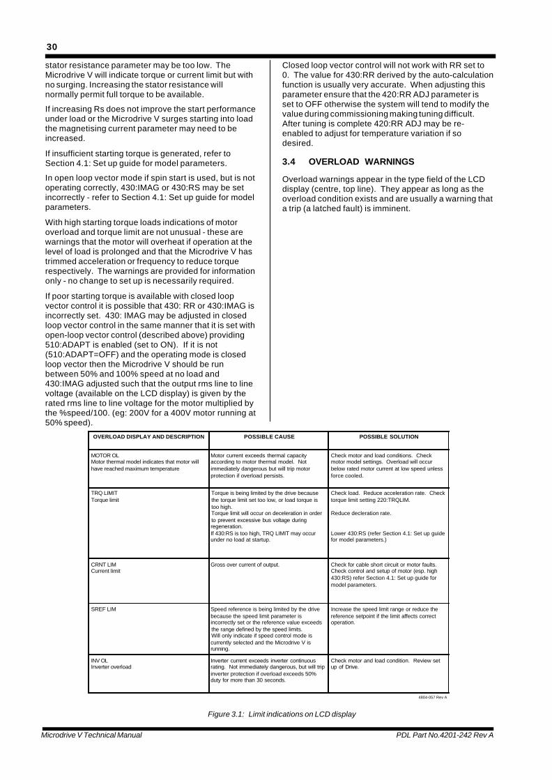
3.4 OVERLOAD WARNINGS
Overload warnings appear in the type field of the LCDdisplay (centre, top line). They appear as long as theoverload condition exists and are usually a warning thata trip (a latched fault) is imminent.
OVERLOAD DISPLAY AND DESCRIPTION POSSIBLE CAUSE POSSIBLE SOLUTION
MOTOR OLMotor thermal model indicates that motor willhave reached maximum temperature
Motor current exceeds thermal capacityaccording to motor thermal model. Notimmediately dangerous but will trip motorprotection if overload persists.
Check motor and load conditions. Checkmotor model settings. Overload will occurbelow rated motor current at low speed unlessforce cooled.
TRQ LIMITTorque limit
Torque is being limited by the drive becausethe torque limit set too low, or load torque istoo high.Torque limit will occur on deceleration in orderto prevent excessive bus voltage duringregeneration.If 430:RS is too high, TRQ LIMIT may occurunder no load at startup.
Check load. Reduce acceleration rate. Checktorque limit setting 220:TRQLIM.
Reduce decleration rate.
Lower 430:RS (refer Section 4.1: Set up guidefor model parameters.)
CRNT LIMCurrent limit
Gross over current of output. Check for cable short circuit or motor faults.Check control and setup of motor (esp. high430:RS) refer Section 4.1: Set up guide formodel parameters.
SREF LIM Speed reference is being limited by the drivebecause the speed limit parameter isincorrectly set or the reference value exceedsthe range defined by the speed limits.Will only indicate if speed control mode iscurrently selected and the Microdrive V isrunning.
Increase the speed limit range or reduce thereference setpoint if the limit affects correctoperation.
INV OLInverter overload
Inverter current exceeds inverter continuousrating. Not immediately dangerous, but will tripinverter protection if overload exceeds 50%duty for more than 30 seconds.
Check motor and load condition. Review setup of Drive.
4804-057 Rev A
Figure 3.1: Limit indications on LCD display
Microdrive V Technical Manual PDL Part No.4201-242 Rev A
31
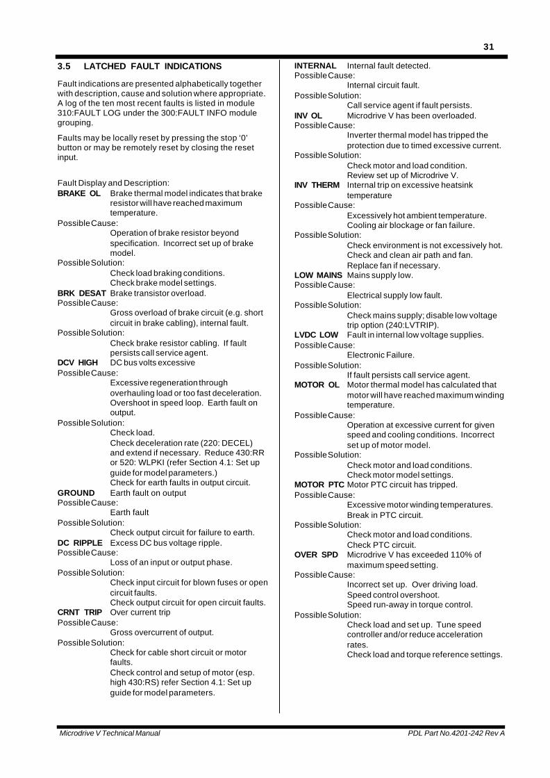
3.5 LATCHED FAULT INDICATIONS
Fault indications are presented alphabetically togetherwith description, cause and solution where appropriate.A log of the ten most recent faults is listed in module310:FAULT LOG under the 300:FAULT INFO modulegrouping.
Faults may be locally reset by pressing the stop ‘0’button or may be remotely reset by closing the resetinput.
Fault Display and Description:BRAKE OL Brake thermal model indicates that brake
resistor will have reached maximumtemperature.
Possible Cause:Operation of brake resistor beyondspecification. Incorrect set up of brakemodel.
Possible Solution:Check load braking conditions.Check brake model settings.
BRK DESAT Brake transistor overload.Possible Cause:
Gross overload of brake circuit (e.g. shortcircuit in brake cabling), internal fault.
Possible Solution:Check brake resistor cabling. If faultpersists call service agent.
DCV HIGH DC bus volts excessivePossible Cause:
Excessive regeneration throughoverhauling load or too fast deceleration.Overshoot in speed loop. Earth fault onoutput.
Possible Solution:Check load.Check deceleration rate (220: DECEL)and extend if necessary. Reduce 430:RRor 520: WLPKI (refer Section 4.1: Set upguide for model parameters.)Check for earth faults in output circuit.
GROUND Earth fault on outputPossible Cause:
Earth faultPossible Solution:
Check output circuit for failure to earth.DC RIPPLE Excess DC bus voltage ripple.Possible Cause:
Loss of an input or output phase.Possible Solution:
Check input circuit for blown fuses or opencircuit faults.Check output circuit for open circuit faults.
CRNT TRIP Over current tripPossible Cause:
Gross overcurrent of output.Possible Solution:
Check for cable short circuit or motorfaults.Check control and setup of motor (esp.high 430:RS) refer Section 4.1: Set upguide for model parameters.
INTERNAL Internal fault detected.Possible Cause:
Internal circuit fault.Possible Solution:
Call service agent if fault persists.INV OL Microdrive V has been overloaded.Possible Cause:
Inverter thermal model has tripped theprotection due to timed excessive current.
Possible Solution:Check motor and load condition.Review set up of Microdrive V.
INV THERM Internal trip on excessive heatsinktemperature
Possible Cause:Excessively hot ambient temperature.Cooling air blockage or fan failure.
Possible Solution:Check environment is not excessively hot.Check and clean air path and fan.Replace fan if necessary.
LOW MAINS Mains supply low.Possible Cause:
Electrical supply low fault.Possible Solution:
Check mains supply; disable low voltagetrip option (240:LVTRIP).
LVDC LOW Fault in internal low voltage supplies.Possible Cause:
Electronic Failure.Possible Solution:
If fault persists call service agent.MOTOR OL Motor thermal model has calculated that
motor will have reached maximum windingtemperature.
Possible Cause:Operation at excessive current for givenspeed and cooling conditions. Incorrectset up of motor model.
Possible Solution:Check motor and load conditions.Check motor model settings.
MOTOR PTC Motor PTC circuit has tripped.Possible Cause:
Excessive motor winding temperatures.Break in PTC circuit.
Possible Solution:Check motor and load conditions.Check PTC circuit.
OVER SPD Microdrive V has exceeded 110% ofmaximum speed setting.
Possible Cause:Incorrect set up. Over driving load.Speed control overshoot.Speed run-away in torque control.
Possible Solution:Check load and set up. Tune speedcontroller and/or reduce accelerationrates.Check load and torque reference settings.
Microdrive V Technical Manual PDL Part No.4201-242 Rev A
32
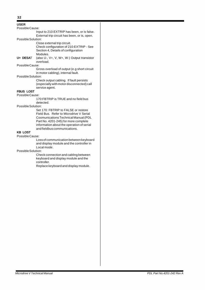
USERPossible Cause:
Input to 210:EXTRIP has been, or is false.External trip circuit has been, or is, open.
Possible Solution:Close external trip circuit.Check configuration of 210:EXTRIP - SeeSection 4, Details of configurationModules.
U+ DESAT (also U-, V+, V, W+, W-) Output transistoroverload.
Possible Cause:Gross overload of output (e.g short circuitin motor cabling), internal fault.
Possible Solution:Check output cabling. If fault persists(especially with motor disconnected) callservice agent.
FBUS LOSTPossible Cause:
170:FBTRIP is TRUE and no field busdetected.
Possible Solution:Set 170: FBTRIP to FALSE or restoreField Bus. Refer to Microdrive V SerialCoomunications Technical Manual (PDLPart No. 4201-245) for more completeinformation about the operation of serialand fieldbus communications.
KB LOSTPossible Cause:
Loss of communication between keyboardand display module and the controller inLocal mode.
Possible Solution:Check connection and cabling betweenkeyboard and display module and thecontroller.Replace keyboard and display module.
Microdrive V Technical Manual PDL Part No.4201-242 Rev A
33
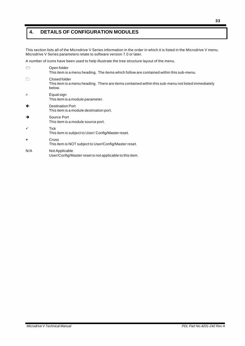
4. DETAILS OF CONFIGURATION MODULES
This section lists all of the Microdrive V Series information in the order in which it is listed in the Microdrive V menu.Microdrive V Series parameters relate to software version 7.0 or later.
A number of icons have been used to help illustrate the tree structure layout of the menu.
1 Open folderThis item is a menu heading. The items which follow are contained within this sub-menu.
0 Closed folderThis item is a menu heading. There are items contained within this sub-menu not listed immediatelybelow.
= Equal signThis item is a module parameter.
ç Destination PortThis item is a module destination port.
è Source PortThis item is a module source port.
ü TickThis item is subject to User/ Config/Master reset.
û CrossThis item is NOT subject to User/Config/Master reset.
N/A Not ApplicableUser/Config/Master reset is not applicable to this item.
Microdrive V Technical Manual PDL Part No.4201-242 Rev A
34
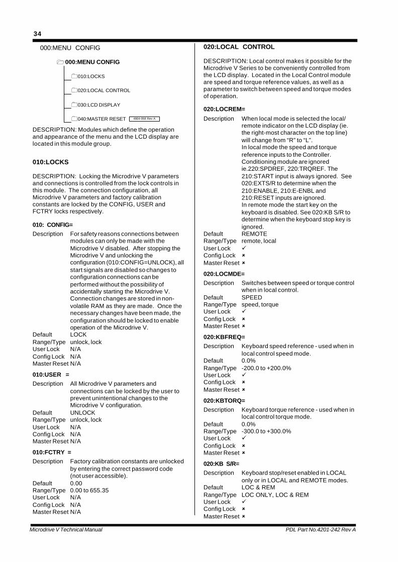
000:MENU CONFIG
1000:MENU CONFIG
0010:LOCKS
0020:LOCAL CONTROL
0030:LCD DISPLAY
0040:MASTER RESET 4804-058 Rev A
DESCRIPTION: Modules which define the operationand appearance of the menu and the LCD display arelocated in this module group.
010:LOCKS
DESCRIPTION: Locking the Microdrive V parametersand connections is controlled from the lock controls inthis module. The connection configuration, allMicrodrive V parameters and factory calibrationconstants are locked by the CONFIG, USER andFCTRY locks respectively.
010: CONFIG=Description For safety reasons connections between
modules can only be made with theMicrodrive V disabled. After stopping theMicrodrive V and unlocking theconfiguration (010:CONFIG=UNLOCK), allstart signals are disabled so changes toconfiguration connections can beperformed without the possibility ofaccidentally starting the Microdrive V.Connection changes are stored in non-volatile RAM as they are made. Once thenecessary changes have been made, theconfiguration should be locked to enableoperation of the Microdrive V.
Default LOCKRange/Type unlock, lockUser Lock N/AConfig Lock N/AMaster Reset N/A
010:USER =Description All Microdrive V parameters and
connections can be locked by the user toprevent unintentional changes to theMicrodrive V configuration.
Default UNLOCKRange/Type unlock, lockUser Lock N/AConfig Lock N/AMaster Reset N/A
010:FCTRY =Description Factory calibration constants are unlocked
by entering the correct password code(not user accessible).
Default 0.00Range/Type 0.00 to 655.35User Lock N/AConfig Lock N/AMaster Reset N/A
020:LOCAL CONTROL
DESCRIPTION: Local control makes it possible for theMicrodrive V Series to be conveniently controlled fromthe LCD display. Located in the Local Control moduleare speed and torque reference values, as well as aparameter to switch between speed and torque modesof operation.
020:LOCREM=
Description When local mode is selected the local/remote indicator on the LCD display (ie.the right-most character on the top line)will change from “R” to “L”.In local mode the speed and torquereference inputs to the Controller.Conditioning module are ignoredie.220:SPDREF, 220:TRQREF. The210:START input is always ignored. See020:EXTS/R to determine when the210:ENABLE, 210:E-ENBL and210:RESET inputs are ignored.In remote mode the start key on thekeyboard is disabled. See 020:KB S/R todetermine when the keyboard stop key isignored.
Default REMOTERange/Type remote, localUser Lock üConfig Lock ûMaster Reset û
020:LOCMDE=Description Switches between speed or torque control
when in local control.Default SPEEDRange/Type speed, torqueUser Lock üConfig Lock ûMaster Reset û
020:KBFREQ=Description Keyboard speed reference - used when in
local control speed mode.Default 0.0%Range/Type -200.0 to +200.0%User Lock üConfig Lock ûMaster Reset û
020:KBTORQ=Description Keyboard torque reference - used when in
local control torque mode.Default 0.0%Range/Type -300.0 to +300.0%User Lock üConfig Lock ûMaster Reset û
020:KB S/R=Description Keyboard stop/reset enabled in LOCAL
only or in LOCAL and REMOTE modes.Default LOC & REMRange/Type LOC ONLY, LOC & REMUser Lock üConfig Lock ûMaster Reset û
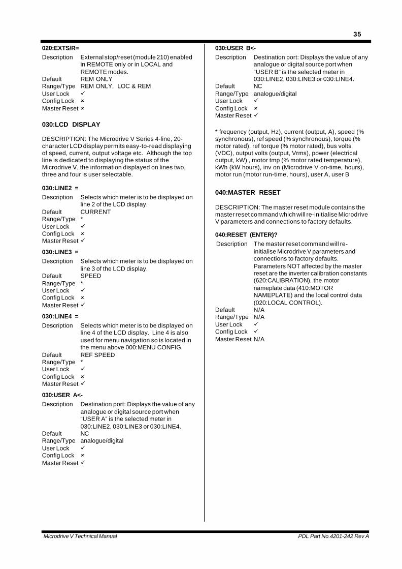
Microdrive V Technical Manual PDL Part No.4201-242 Rev A
35
020:EXTS/R=Description External stop/reset (module 210) enabled
in REMOTE only or in LOCAL andREMOTE modes.
Default REM ONLYRange/Type REM ONLY, LOC & REMUser Lock üConfig Lock ûMaster Reset û
030:LCD DISPLAY
DESCRIPTION: The Microdrive V Series 4-line, 20-character LCD display permits easy-to-read displayingof speed, current, output voltage etc. Although the topline is dedicated to displaying the status of theMicrodrive V, the information displayed on lines two,three and four is user selectable.
030:LINE2 =Description Selects which meter is to be displayed on
line 2 of the LCD display.Default CURRENTRange/Type *User Lock üConfig Lock ûMaster Reset ü
030:LINE3 =Description Selects which meter is to be displayed on
line 3 of the LCD display.Default SPEEDRange/Type *User Lock üConfig Lock ûMaster Reset ü
030:LINE4 =Description Selects which meter is to be displayed on
line 4 of the LCD display. Line 4 is alsoused for menu navigation so is located inthe menu above 000:MENU CONFIG.
Default REF SPEEDRange/Type *User Lock üConfig Lock ûMaster Reset ü
030:USER A<-Description Destination port: Displays the value of any
analogue or digital source port when“USER A” is the selected meter in030:LINE2, 030:LINE3 or 030:LINE4.
Default NCRange/Type analogue/digitalUser Lock üConfig Lock ûMaster Reset ü
030:USER B<-Description Destination port: Displays the value of any
analogue or digital source port when“USER B” is the selected meter in030:LINE2, 030:LINE3 or 030:LINE4.
Default NCRange/Type analogue/digitalUser Lock üConfig Lock ûMaster Reset ü
* frequency (output, Hz), current (output, A), speed (%synchronous), ref speed (% synchronous), torque (%motor rated), ref torque (% motor rated), bus volts(VDC), output volts (output, Vrms), power (electricaloutput, kW) , motor tmp (% motor rated temperature),kWh (kW hours), inv on (Microdrive V on-time, hours),motor run (motor run-time, hours), user A, user B
040:MASTER RESET
DESCRIPTION: The master reset module contains themaster reset command which will re-initialise MicrodriveV parameters and connections to factory defaults.
040:RESET (ENTER)? Description The master reset command will re-
initialise Microdrive V parameters andconnections to factory defaults.Parameters NOT affected by the masterreset are the inverter calibration constants(620:CALIBRATION), the motornameplate data (410:MOTORNAMEPLATE) and the local control data(020:LOCAL CONTROL).
Default N/ARange/Type N/AUser Lock üConfig Lock üMaster Reset N/A
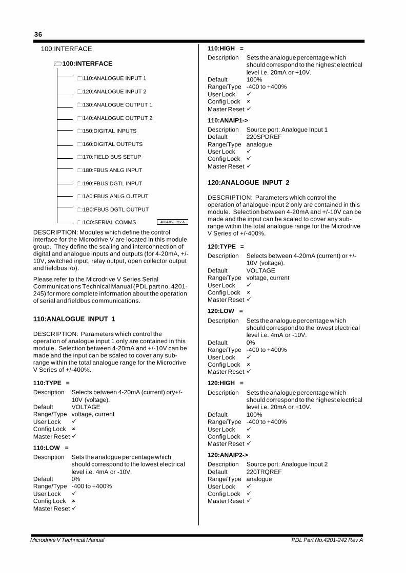
Microdrive V Technical Manual PDL Part No.4201-242 Rev A
36
100:INTERFACE
1100:INTERFACE
0110:ANALOGUE INPUT 1
0120:ANALOGUE INPUT 2
0130:ANALOGUE OUTPUT 1
0140:ANALOGUE OUTPUT 2
0150:DIGITAL INPUTS
0160:DIGITAL OUTPUTS
0170:FIELD BUS SETUP
0180:FBUS ANLG INPUT
0190:FBUS DGTL INPUT
01A0:FBUS ANLG OUTPUT
01B0:FBUS DGTL OUTPUT
01C0:SERIAL COMMS 4804-059 Rev A
DESCRIPTION: Modules which define the controlinterface for the Microdrive V are located in this modulegroup. They define the scaling and interconnection ofdigital and analogue inputs and outputs (for 4-20mA, +/-10V, switched input, relay output, open collector outputand fieldbus i/o).
Please refer to the Microdrive V Series SerialCommunications Technical Manual (PDL part no. 4201-245) for more complete information about the operationof serial and fieldbus communications.
110:ANALOGUE INPUT 1
DESCRIPTION: Parameters which control theoperation of analogue input 1 only are contained in thismodule. Selection between 4-20mA and +/-10V can bemade and the input can be scaled to cover any sub-range within the total analogue range for the MicrodriveV Series of +/-400%.
110:TYPE =Description Selects between 4-20mA (current) orÿ+/-
10V (voltage).Default VOLTAGERange/Type voltage, currentUser Lock üConfig Lock ûMaster Reset ü
110:LOW =Description Sets the analogue percentage which
should correspond to the lowest electricallevel i.e. 4mA or -10V.
Default 0%Range/Type -400 to +400%User Lock üConfig Lock ûMaster Reset ü
110:HIGH =Description Sets the analogue percentage which
should correspond to the highest electricallevel i.e. 20mA or +10V.
Default 100%Range/Type -400 to +400%User Lock üConfig Lock ûMaster Reset ü
110:ANAIP1->Description Source port: Analogue Input 1Default 220SPDREFRange/Type analogueUser Lock üConfig Lock üMaster Reset ü
120:ANALOGUE INPUT 2
DESCRIPTION: Parameters which control theoperation of analogue input 2 only are contained in thismodule. Selection between 4-20mA and +/-10V can bemade and the input can be scaled to cover any sub-range within the total analogue range for the MicrodriveV Series of +/-400%.
120:TYPE =Description Selects between 4-20mA (current) or +/-
10V (voltage).Default VOLTAGERange/Type voltage, currentUser Lock üConfig Lock ûMaster Reset ü
120:LOW =
Description Sets the analogue percentage whichshould correspond to the lowest electricallevel i.e. 4mA or -10V.
Default 0%Range/Type -400 to +400%User Lock üConfig Lock ûMaster Reset ü
120:HIGH =
Description Sets the analogue percentage whichshould correspond to the highest electricallevel i.e. 20mA or +10V.
Default 100%Range/Type -400 to +400%User Lock üConfig Lock ûMaster Reset ü
120:ANAIP2->Description Source port: Analogue Input 2Default 220TRQREFRange/Type analogueUser Lock üConfig Lock üMaster Reset ü

Microdrive V Technical Manual PDL Part No.4201-242 Rev A
37
130:ANALOGUE OUTPUT 1
DESCRIPTION: Parameters which control theoperation of analogue output 1 only are contained inthis module. Selection between 4-20mA and +/-10Vcan be made and the output can be scaled to cover anysub-range within the total analogue range of +/-400%
130:TYPE =
Description Selects between 4-20mA (current) or +/-10V (voltage).
Default VOLTAGERange/Type voltage, currentUser Lock üConfig Lock ûMaster Reset ü
130:LOW =Description Sets the analogue percentage which
should correspond to the lowest electricallevel i.e. 4mA or -10V.
Default 0%Range/Type -400 to +400%User Lock üConfig Lock ûMaster Reset ü
130:HIGH =Description Sets the analogue percentage which
should correspond to the highest electricallevel i.e. 20mA or +10V.
Default 100%Range/Type -400 to +400%User Lock üConfig Lock ûMaster Reset ü
130:ANAOP1<-Description Destination port: Analogue Output 1Default 230SPEEDRange/Type analogueUser Lock üConfig Lock üMaster Reset ü
140:ANALOGUE OUTPUT 2
DESCRIPTION: Parameters which control theoperation of analogue output 2 only are contained inthis module. Selection between 4-20mA and +/-10Vcan be made and the output can be scaled to cover anysub-range within the total analogue range of +/-400%.
140:TYPE =Description Selects between 4-20mA (current) or +/-
10V (voltage).Default VOLTAGERange/Type voltage, currentUser Lock üConfig Lock ûMaster Reset ü
140:LOW =Description Sets the analogue percentage which
should correspond to the lowest electricallevel i.e. 4mA or -10V.
Default 0%Range/Type -400 to +400%User Lock üConfig Lock ûMaster Reset ü
140:HIGH =Description Sets the analogue percentage which
should correspond to the highest electricallevel i.e. 20mA or +10V.
Default 100%Range/Type -400 to +400%User Lock üConfig Lock ûMaster Reset ü
140:ANAOP2<-Description Destination port: Analogue Output 2Default 230MTRCURRange/Type analogueUser Lock üConfig Lock üMaster Reset ü
150:DIGITAL INPUTS
DESCRIPTION: Source ports for the control boardmulitfunction digital inputs.
150:DIGIP1->
Description Source port: Digital input 1.Default 210STARTRange/Type digitalUser Lock üConfig Lock üMaster Reset ü
150:DIGIP2->Description Source port: Digital input 2.Default 210ENABLERange/Type digitalUser Lock üConfig Lock üMaster Reset ü
150:DIGIP3->Description Source port: Digital input 3.Default 210RESETRange/Type digitalUser Lock üConfig Lock üMaster Reset ü
150:DIGIP4->Description Source port: Digital input 4.Default 220TRQMDERange/Type digitalUser Lock üConfig Lock üMaster Reset ü
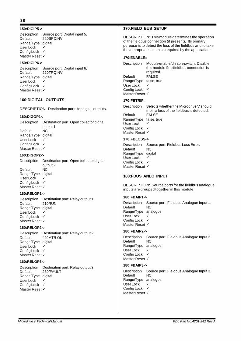
Microdrive V Technical Manual PDL Part No.4201-242 Rev A
38
150:DIGIP5->Description Source port: Digital input 5.Default 220SPDINVRange/Type digitalUser Lock üConfig Lock üMaster Reset ü
150:DIGIP6->Description Source port: Digital input 6.Default 220TRQINVRange/Type digitalUser Lock üConfig Lock üMaster Reset ü
160:DIGITAL OUTPUTS
DESCRIPTION: Destination ports for digital outputs.
160:DIGOP1<-Description Destination port: Open collector digital
output 1Default NCRange/Type digitalUser Lock üConfig Lock üMaster Reset ü
160:DIGOP2<-Description Destination port: Open collector digital
output 2Default NCRange/Type digitalUser Lock üConfig Lock üMaster Reset ü
160:RELOP1<-Description Destination port: Relay output 1Default 210RUNRange/Type digitalUser Lock üConfig Lock üMaster Reset ü
160:RELOP2<-Description Destination port: Relay output 2Default 420MTR OLRange/Type digitalUser Lock üConfig Lock üMaster Reset ü
160:RELOP3<-
Description Destination port: Relay output 3Default 230/FAULTRange/Type digitalUser Lock üConfig Lock üMaster Reset ü
170:FIELD BUS SETUP
DESCRIPTION: This module determines the operationof the fieldbus connection (if present). Its primarypurpose is to detect the loss of the fieldbus and to takethe appropriate action as required by the application.
170:ENABLE=
Description Module enable/disable switch. Disablethis module if no fieldbus connection isrequired.
Default FALSERange/Type false, trueUser Lock üConfig Lock üMaster Reset ü
170:FBTRIP=
Description Selects whether the Microdrive V shouldtrip if a loss of the fieldbus is detected.
Default FALSERange/Type false, trueUser Lock üConfig Lock üMaster Reset ü
170:FBLOSS->Description Source port: Fieldbus Loss Error.Default NCRange/Type digitalUser Lock üConfig Lock üMaster Reset ü
180:FBUS ANLG INPUT
DESCRIPTION: Source ports for the fieldbus analogueinputs are grouped together in this module.
180:FBAIP1->Description Source port: Fieldbus Analogue Input 1.Default NCRange/Type analogueUser Lock üConfig Lock üMaster Reset ü
180:FBAIP2->
Description Source port: Fieldbus Analogue Input 2.Default NCRange/Type analogueUser Lock üConfig Lock üMaster Reset ü
180:FBAIP3->
Description Source port: Fieldbus Analogue Input 3.Default NCRange/Type analogueUser Lock üConfig Lock üMaster Reset ü
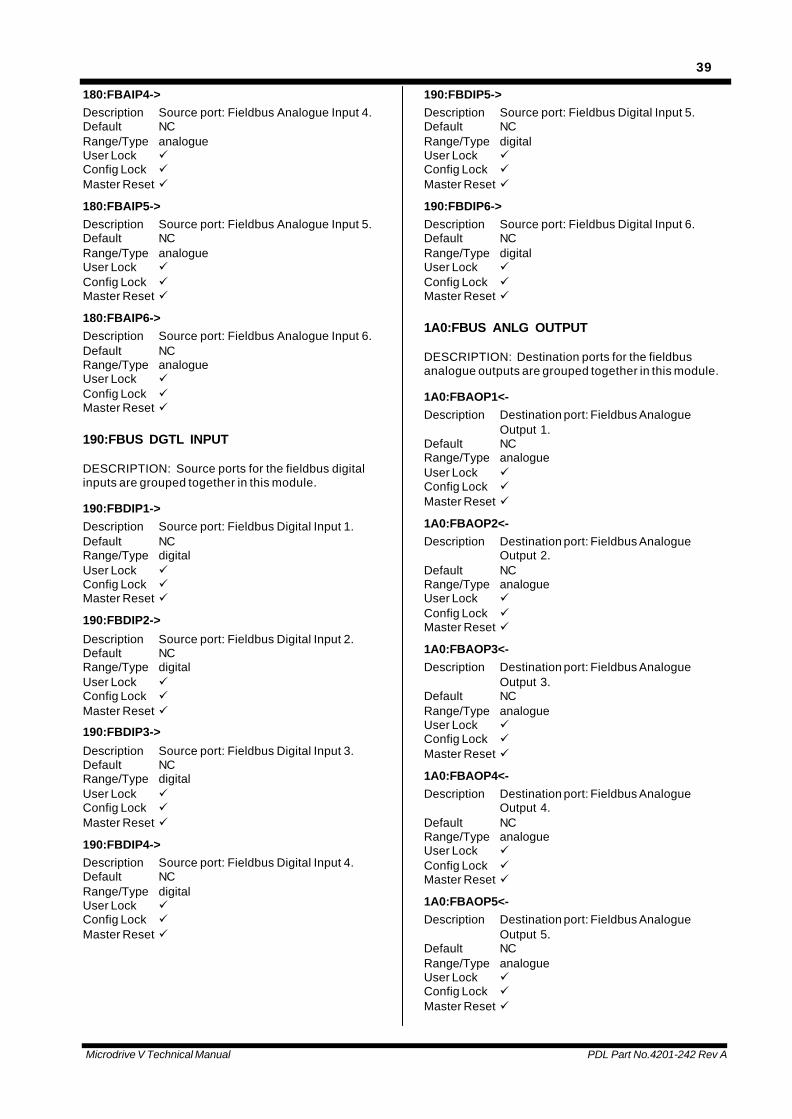
Microdrive V Technical Manual PDL Part No.4201-242 Rev A
39
180:FBAIP4->Description Source port: Fieldbus Analogue Input 4.Default NCRange/Type analogueUser Lock üConfig Lock üMaster Reset ü
180:FBAIP5->Description Source port: Fieldbus Analogue Input 5.Default NCRange/Type analogueUser Lock üConfig Lock üMaster Reset ü
180:FBAIP6->Description Source port: Fieldbus Analogue Input 6.Default NCRange/Type analogueUser Lock üConfig Lock üMaster Reset ü
190:FBUS DGTL INPUT
DESCRIPTION: Source ports for the fieldbus digitalinputs are grouped together in this module.
190:FBDIP1->Description Source port: Fieldbus Digital Input 1.Default NCRange/Type digitalUser Lock üConfig Lock üMaster Reset ü
190:FBDIP2->
Description Source port: Fieldbus Digital Input 2.Default NCRange/Type digitalUser Lock üConfig Lock üMaster Reset ü
190:FBDIP3->
Description Source port: Fieldbus Digital Input 3.Default NCRange/Type digitalUser Lock üConfig Lock üMaster Reset ü
190:FBDIP4->Description Source port: Fieldbus Digital Input 4.Default NCRange/Type digitalUser Lock üConfig Lock üMaster Reset ü
190:FBDIP5->Description Source port: Fieldbus Digital Input 5.Default NCRange/Type digitalUser Lock üConfig Lock üMaster Reset ü
190:FBDIP6->Description Source port: Fieldbus Digital Input 6.Default NCRange/Type digitalUser Lock üConfig Lock üMaster Reset ü
1A0:FBUS ANLG OUTPUT
DESCRIPTION: Destination ports for the fieldbusanalogue outputs are grouped together in this module.
1A0:FBAOP1<-Description Destination port: Fieldbus Analogue
Output 1.Default NCRange/Type analogueUser Lock üConfig Lock üMaster Reset ü
1A0:FBAOP2<-Description Destination port: Fieldbus Analogue
Output 2.Default NCRange/Type analogueUser Lock üConfig Lock üMaster Reset ü
1A0:FBAOP3<-Description Destination port: Fieldbus Analogue
Output 3.Default NCRange/Type analogueUser Lock üConfig Lock üMaster Reset ü
1A0:FBAOP4<-Description Destination port: Fieldbus Analogue
Output 4.Default NCRange/Type analogueUser Lock üConfig Lock üMaster Reset ü
1A0:FBAOP5<-Description Destination port: Fieldbus Analogue
Output 5.Default NCRange/Type analogueUser Lock üConfig Lock üMaster Reset ü
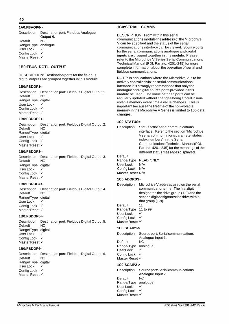
Microdrive V Technical Manual PDL Part No.4201-242 Rev A
40
1A0:FBAOP6<-Description Destination port: Fieldbus Analogue
Output 6.Default NCRange/Type analogueUser Lock üConfig Lock üMaster Reset ü
1B0:FBUS DGTL OUTPUT
DESCRIPTION: Destination ports for the fieldbusdigital outputs are grouped together in this module.
1B0:FBDOP1<-
Description Destination port: Fieldbus Digital Output 1.Default NCRange/Type digitalUser Lock üConfig Lock üMaster Reset ü
1B0:FBDOP2<-
Description Destination port: Fieldbus Digital Output 2.Default NCRange/Type digitalUser Lock üConfig Lock üMaster Reset ü
1B0:FBDOP3<-Description Destination port: Fieldbus Digital Output 3.Default NCRange/Type digitalUser Lock üConfig Lock üMaster Reset ü
1B0:FBDOP4<-Description Destination port: Fieldbus Digital Output 4.Default NCRange/Type digitalUser Lock üConfig Lock üMaster Reset ü
1B0:FBDOP5<-Description Destination port: Fieldbus Digital Output 5.Default NCRange/Type digitalUser Lock üConfig Lock üMaster Reset ü
1B0:FBDOP6<-Description Destination port: Fieldbus Digital Output 6.Default NCRange/Type digitalUser Lock üConfig Lock üMaster Reset ü
1C0:SERIAL COMMS
DESCRIPTION: From within this serialcommunications module the address of the MicrodriveV can be specified and the status of the serialcommunications interface can be viewed. Source portsfor the serial communications analogue and digitalinputs are grouped together in this module. Pleaserefer to the Microdrive V Series Serial CommunicationsTechnical Manual (PDL Part no. 4201-245) for morecomplete information about the operation of serial andfieldbus communications.
NOTE: In applications where the Microdrive V is to beactively controlled via the serial communicationsinterface it is strongly recommended that only theanalogue and digital source ports provided in thismodule be used. The value of these ports can beregularly updated without changes being stored in non-volatile memory every time a value changes. This isimportant because the lifetime of the non-volatilememory in the Microdrive V Series is limited to 106 datachanges.
1C0:STATUS=Description Status of the serial communications
interface. Refer to the section “MicrodriveV serial communiations parameter statusindex numbers” in the SerialCommunications Technical Manual (PDLPart no. 4201-245) for the meanings of thedifferent status messages displayed.
DefaultRange/Type READ ONLYUser Lock N/AConfig Lock N/AMaster Reset N/A
1C0:ADDRSS=Description Microdrive V address used on the serial
communications line. The first digitdesignates the drive group (1-9) and thesecond digit designates the drive withinthat group (1-9).
Default 11Range/Type 11 to 99User Lock üConfig Lock üMaster Reset ü
1C0:SCAIP1->
Description Source port: Serial communicationsAnalogue Input 1.
Default NCRange/Type analogueUser Lock üConfig Lock üMaster Reset ü
1C0:SCAIP2->Description Source port: Serial communications
Analogue Input 2.Default NCRange/Type analogueUser Lock üConfig Lock üMaster Reset ü
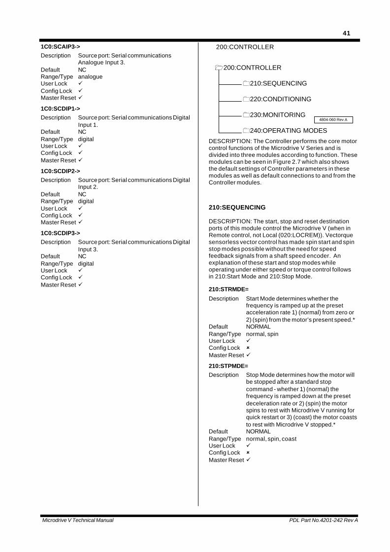
Microdrive V Technical Manual PDL Part No.4201-242 Rev A
41
1C0:SCAIP3->Description Source port: Serial communications
Analogue Input 3.Default NCRange/Type analogueUser Lock üConfig Lock üMaster Reset ü
1C0:SCDIP1->Description Source port: Serial communications Digital
Input 1.Default NCRange/Type digitalUser Lock üConfig Lock üMaster Reset ü
1C0:SCDIP2->Description Source port: Serial communications Digital
Input 2.Default NCRange/Type digitalUser Lock üConfig Lock üMaster Reset ü
1C0:SCDIP3->Description Source port: Serial communications Digital
Input 3.Default NCRange/Type digitalUser Lock üConfig Lock üMaster Reset ü
200:CONTROLLER
1200:CONTROLLER
0210:SEQUENCING
0220:CONDITIONING
0230:MONITORING
0240:OPERATING MODES
4804-060 Rev A
DESCRIPTION: The Controller performs the core motorcontrol functions of the Microdrive V Series and isdivided into three modules according to function. Thesemodules can be seen in Figure 2.7 which also showsthe default settings of Controller parameters in thesemodules as well as default connections to and from theController modules.
210:SEQUENCING
DESCRIPTION: The start, stop and reset destinationports of this module control the Microdrive V (when inRemote control, not Local (020:LOCREM)). Vectorquesensorless vector control has made spin start and spinstop modes possible without the need for speedfeedback signals from a shaft speed encoder. Anexplanation of these start and stop modes whileoperating under either speed or torque control followsin 210:Start Mode and 210:Stop Mode.
210:STRMDE=
Description Start Mode determines whether thefrequency is ramped up at the presetacceleration rate 1) (normal) from zero or2) (spin) from the motor’s present speed.*
Default NORMALRange/Type normal, spinUser Lock üConfig Lock ûMaster Reset ü
210:STPMDE=Description Stop Mode determines how the motor will
be stopped after a standard stopcommand - whether 1) (normal) thefrequency is ramped down at the presetdeceleration rate or 2) (spin) the motorspins to rest with Microdrive V running forquick restart or 3) (coast) the motor coaststo rest with Microdrive V stopped.*
Default NORMALRange/Type normal, spin, coastUser Lock üConfig Lock ûMaster Reset ü
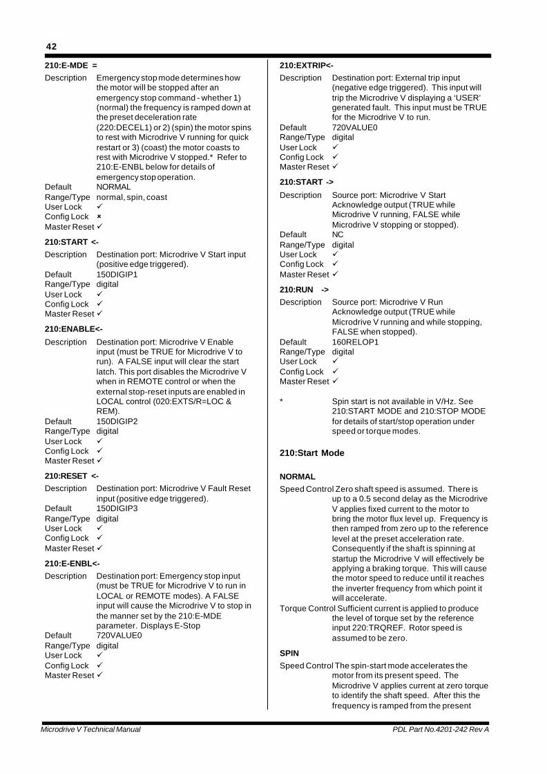
Microdrive V Technical Manual PDL Part No.4201-242 Rev A
42
210:E-MDE =Description Emergency stop mode determines how
the motor will be stopped after anemergency stop command - whether 1)(normal) the frequency is ramped down atthe preset deceleration rate(220:DECEL1) or 2) (spin) the motor spinsto rest with Microdrive V running for quickrestart or 3) (coast) the motor coasts torest with Microdrive V stopped.* Refer to210:E-ENBL below for details ofemergency stop operation.
Default NORMALRange/Type normal, spin, coastUser Lock üConfig Lock ûMaster Reset ü
210:START <-Description Destination port: Microdrive V Start input
(positive edge triggered).Default 150DIGIP1Range/Type digitalUser Lock üConfig Lock üMaster Reset ü
210:ENABLE<-
Description Destination port: Microdrive V Enableinput (must be TRUE for Microdrive V torun). A FALSE input will clear the startlatch. This port disables the Microdrive Vwhen in REMOTE control or when theexternal stop-reset inputs are enabled inLOCAL control (020:EXTS/R=LOC &REM).
Default 150DIGIP2Range/Type digitalUser Lock üConfig Lock üMaster Reset ü
210:RESET <-Description Destination port: Microdrive V Fault Reset
input (positive edge triggered).Default 150DIGIP3Range/Type digitalUser Lock üConfig Lock üMaster Reset ü
210:E-ENBL<-Description Destination port: Emergency stop input
(must be TRUE for Microdrive V to run inLOCAL or REMOTE modes). A FALSEinput will cause the Microdrive V to stop inthe manner set by the 210:E-MDEparameter. Displays E-Stop
Default 720VALUE0Range/Type digitalUser Lock üConfig Lock üMaster Reset ü
210:EXTRIP<-Description Destination port: External trip input
(negative edge triggered). This input willtrip the Microdrive V displaying a ‘USER’generated fault. This input must be TRUEfor the Microdrive V to run.
Default 720VALUE0Range/Type digitalUser Lock üConfig Lock üMaster Reset ü
210:START ->
Description Source port: Microdrive V StartAcknowledge output (TRUE whileMicrodrive V running, FALSE whileMicrodrive V stopping or stopped).
Default NCRange/Type digitalUser Lock üConfig Lock üMaster Reset ü
210:RUN ->Description Source port: Microdrive V Run
Acknowledge output (TRUE whileMicrodrive V running and while stopping,FALSE when stopped).
Default 160RELOP1Range/Type digitalUser Lock üConfig Lock üMaster Reset ü
* Spin start is not available in V/Hz. See210:START MODE and 210:STOP MODEfor details of start/stop operation underspeed or torque modes.
210:Start Mode
NORMALSpeed Control Zero shaft speed is assumed. There is
up to a 0.5 second delay as the MicrodriveV applies fixed current to the motor tobring the motor flux level up. Frequency isthen ramped from zero up to the referencelevel at the preset acceleration rate.Consequently if the shaft is spinning atstartup the Microdrive V will effectively beapplying a braking torque. This will causethe motor speed to reduce until it reachesthe inverter frequency from which point itwill accelerate.
Torque Control Sufficient current is applied to producethe level of torque set by the referenceinput 220:TRQREF. Rotor speed isassumed to be zero.
SPINSpeed Control The spin-start mode accelerates the
motor from its present speed. TheMicrodrive V applies current at zero torqueto identify the shaft speed. After this thefrequency is ramped from the present
Microdrive V Technical Manual PDL Part No.4201-242 Rev A
43
shaft speed to the reference levelaccording to the preset acceleration ramprates.#*
Torque Control The spin-start mode accelerates themotor from its present speed. TheMicrodrive V applies current at zero torqueto identify the shaft speed. Afterapproximately one second the referencetorque level is applied. #*
# In low inertia systems the shaft may rotateat zero speed in spin start. If this is aproblem, use NORMAL start mode.
* Spin start is not applicable to V/Hz mode.The Microdrive V controller will revert toNORMAL start.
210: Stop Mode
NORMALSpeed Control The frequency is ramped down to zero at
the preset deceleration rate.Torque Control A small drag torque is applied allowing
the load to decelerate the motor. TheMicrodrive V knows the shaft speed as itdecelerates, permitting an instantaneoustransition into acceleration from thepresent speed if required. The shaft willcoast to rest below 10% speed.
SPINSpeed Control A small drag torque is applied allowing
the load to decelerate the motor. TheMicrodrive V knows the shaft speed as itdecelerates, permitting an instantaneoustransition into acceleration from thepresent speed if required. The shaft willcoast to rest below 10% speed.
Torque Control A small drag torque is applied allowingthe load to decelerate the motor. TheMicrodrive V knows the shaft speed as itdecelerates, permitting an instantaneoustransition into acceleration from thepresent speed if required. The shaft willcoast to rest below 10% speed.
COASTSpeed Control The Microdrive V applies no power to the
motor, allowing the motor to coast to restas if no Microdrive V were connected.
Torque Control The Microdrive V applies no power to themotor, allowing the motor to coast to restas if no Microdrive V were connected.
If the drag torque which is applied causestoo much deceleration select the COASTstop mode. SPIN stop permits theinverter to be restarted at any point duringthe stopping process without the need forspin start. The speed display remainsaccurate even without encoder feedbackduring the spin stop process.
220:CONDITIONING
DESCRIPTION: Speed and torque control signals areinput to the Conditioning module and are processedtogether with the start/stop sequencing logic to controlthe operation of the Microdrive V. A number of limits(acceleration, deceleration, upper and lower speedlimits, maximum torque limits) set boundaries to thearea of operation of the controller.
220:TRQLIM=
Description Sets the limit for maximum positive andnegative torque magnitude.
Default 150%Range/Type 0 to 300%User Lock üConfig Lock ûMaster Reset ü
220:LWRSPD=Description Sets the lower limit for speed.Default -110%Range/Type -200% to 220:UPSPDUser Lock üConfig Lock ûMaster Reset ü
220:UPSPD =Description Sets the upper limit for speed.Default 110%Range/Type 220:LWRSPD to +200%User Lock üConfig Lock ûMaster Reset ü
220:ACCEL1=Description Sets the ramp-rate group 1 accelerating
limit for the controller. Set as required byprocess. Avoid unnecessarily highacceleration.*
Default 60.0sRange/Type 0.1 to 3000 secondsUser Lock üConfig Lock ûMaster Reset ü
220:DECEL1=Description Sets the ramp-rate group 1 decelerating
limit for the controller. Set as required byprocess. Avoid unnecessarily highdeceleration.
Default 60.0sRange/Type 0.1 to 3000 secondsUser Lock üConfig Lock ûMaster Reset ü
220:ACCEL2=Description Sets the ramp-rate group 2 accelerating
limit for the controller. Set as required byprocess. Avoid unnecessarily highacceleration.*
Default 60.0sRange/Type 0.1 to 3000 secondsUser Lock üConfig Lock ûMaster Reset ü
Microdrive V Technical Manual PDL Part No.4201-242 Rev A
44
220:DECEL2=Description Sets the ramp-rate group 2 decelerating
limit for the Microdrive V. Set as requiredby process. Avoid unnecessarily highdeceleration.
Default 60.0sRange/Type 0.1 to 3000 secondsUser Lock üConfig Lock ûMaster Reset ü
220:SPDREF<-Description Destination port: Speed reference.Default 110ANAIP1Range/Type analogueUser Lock üConfig Lock üMaster Reset ü
220:TRQREF<-Description Destination port: Torque reference.Default 120ANAIP2Range/Type analogueUser Lock üConfig Lock üMaster Reset ü
220:TRQMDE<-Description Destination port: Torque/speed mode
selector (FALSE for speed mode; TRUEfor torque mode).
Default 150DIGIP4Range/Type digitalUser Lock üConfig Lock üMaster Reset ü
220:SPDINV<-Description Destination port: TRUE inverts the sign of
the remote control speed reference.Default NCRange/Type digitalUser Lock üConfig Lock üMaster Reset ü
220:TRQINV<-Description Destination port: TRUE inverts the sign of
the remote control torque reference.Default NCRange/Type digitalUser Lock üConfig Lock üMaster Reset ü
220:RAMP2 <-Description Destination port: TRUE selects ramp-rate
group 2 acceleration/deceleration limits forthe Microdrive V controller. FALSEselects ramp-rate group 1 acceleration/deceleration limits for the Microdrive Vcontroller.
Default NCRange/Type digitalUser Lock üConfig Lock üMaster Reset ü
220:AT SPD->Description Source port: At speed setpoint indicator.Default NCRange/Type digitalUser Lock üConfig Lock üMaster Reset ü
220:CURLIM->Description Source port: Current limit indicator.Default NCRange/Type digitalUser Lock üConfig Lock üMaster Reset ü
220:TRQLIM->Description Source port: Torque limit indicator.Default NCRange/Type digitalUser Lock üConfig Lock üMaster Reset ü
* Value is the time for a 100% change in speed.
230:MONITORING
DESCRIPTION: The Controller Monitoring moduleoutputs a number of useful control variables: MicrodriveV output frequency, shaft speed, applied voltage, motortorque, current, electrical power and a fault indicator.These may be used for control purposes, linked toappropriate interfaces or shown on the LCD display.
230:FREQ ->Description Source port: Microdrive V output
frequency.Default NCRange/Type analogueUser Lock üConfig Lock üMaster Reset ü
230:SPEED ->Description Source port: Motor speed.Default 130ANAOP1Range/Type analogueUser Lock üConfig Lock üMaster Reset ü
230:VOLTS ->Description Source port: Microdrive V output voltage.Default NCRange/Type analogueUser Lock üConfig Lock üMaster Reset ü
Microdrive V Technical Manual PDL Part No.4201-242 Rev A
45
230:TORQUE->Description Source port: Torque.Default NCRange/Type analogueUser Lock üConfig Lock üMaster Reset ü
230:MTRCUR->Description Source port: Current as a percentage of
rated motor current.Default NCRange/Type analogueUser Lock üConfig Lock üMaster Reset ü
230:POWER ->
Description Source port: Electrical output power.Default NCRange/Type analogueUser Lock üConfig Lock üMaster Reset ü
230:FAULT->
Description Source port: Failsafe fault indicator (‘/’indicates inverted logic) ie. TRUE = NoFault. Changes to FALSE for anyMicrodrive V trip condition.
Default 160RELOP3Range/Type digitalUser Lock üConfig Lock üMaster Reset ü
230:INV OL->Description Source port: Inverter overload indicator.Default NCRange/Type digitalUser Lock üConfig Lock üMaster Reset ü
240:OPERATING MODES
DESCRIPTION: The Controller Operating Modesmodule permits selection of a number of differentoperating modes for the Microdrive V.
240:CNTRL =Description Selects 1)V/Hz or 2)Vectorque open loop
or encoderless vector control mode or3)Vectorque closed loop or encoderfeedback mode. Limited torque featuresare available under V/Hz control. Spinstart are only available under theVectorque mode of operation.
Default OPNLP VECRange/Type V/Hz, opnlp vec, encdr vecUser Lock üConfig Lock üMaster Reset ü
240:LOAD =Description Selecting variable torque (“VAR TRQ”)
enables a special pump curve whichprovides reduced flux and noise atfractional speeds - suits centrifugal loads.Set to constant torque (“CONST TRQ”) forall other loads.
Default CONST TRQRange/Type const trq, var trqUser Lock üConfig Lock üMaster Reset ü
240:LVTRIP=Description Forces Microdrive V to trip upon low mains
voltage detection. Disable this option toallow ride-through during mainsdisturbances (Microdrive V output isdisabled during low mains; spin startshould be selected to restart on tospinning motor.
In V/Hz mode the motor will run down to zero speed oncurrent limit).
Default OFFRange/Type off, onUser Lock üConfig Lock üMaster Reset ü
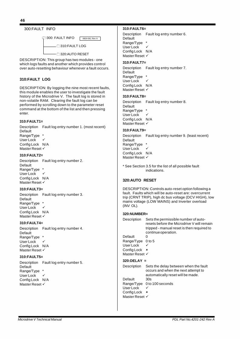
Microdrive V Technical Manual PDL Part No.4201-242 Rev A
46
300:FAULT INFO
1300: FAULT INFO
0310:FAULT LOG
0320:AUTO RESET
4804-061 Rev A
DESCRIPTION: This group has two modules - onewhich logs faults and another which provides controlover auto-resetting behaviour whenever a fault occurs.
310:FAULT LOG
DESCRIPTION: By logging the nine most recent faults,this module enables the user to investigate the faulthistory of the Microdrive V. The fault log is stored innon-volatile RAM. Clearing the fault log can beperformed by scrolling down to the parameter resetcommand at the bottom of the list and then pressingenter.
310:FAULT1=Description Fault log entry number 1. (most recent)DefaultRange/Type *User Lock üConfig Lock N/AMaster Reset ü
310:FAULT2=Description Fault log entry number 2.DefaultRange/Type *User Lock üConfig Lock N/AMaster Reset ü
310:FAULT3=Description Fault log entry number 3.DefaultRange/Type *User Lock üConfig Lock N/AMaster Reset ü
310:FAULT4=Description Fault log entry number 4.DefaultRange/Type *User Lock üConfig Lock N/AMaster Reset ü
310:FAULT5=
Description Fault log entry number 5.DefaultRange/Type *User Lock üConfig Lock N/AMaster Reset ü
310:FAULT6=Description Fault log entry number 6.DefaultRange/Type *User Lock üConfig Lock N/AMaster Reset ü
310:FAULT7=Description Fault log entry number 7.DefaultRange/Type *User Lock üConfig Lock N/AMaster Reset ü
310:FAULT8=Description Fault log entry number 8.DefaultRange/Type *User Lock üConfig Lock N/AMaster Reset ü
310:FAULT9=Description Fault log entry number 9. (least recent)DefaultRange/Type *User Lock üConfig Lock N/AMaster Reset ü
* See Section 3.5 for the list of all possible faultindications.
320:AUTO RESET
DESCRIPTION: Controls auto-reset option following afault. Faults which will be auto-reset are: overcurrenttrip (CRNT TRIP), high dc bus voltage (DCV HIGH), lowmains voltage (LOW MAINS) and Inverter overload(INV OL).
320:NUMBER=Description Sets the permissible number of auto-
resets before the Microdrive V will remaintripped - manual reset is then required tocontinue operation.
Default 0Range/Type 0 to 5User Lock üConfig Lock ûMaster Reset ü
320:DELAY =Description Sets the delay between when the fault
occurs and when the next attempt toautomatically reset will be made.
Default 30sRange/Type 0 to 100 secondsUser Lock üConfig Lock ûMaster Reset ü

Microdrive V Technical Manual PDL Part No.4201-242 Rev A
47
320:PERIOD=Description The fault-free period after which the fault
counter is reset.Default 3600sRange/Type 0 to 3600 secondsUser Lock üConfig Lock ûMaster Reset ü
400:MOTOR
1400: MOTOR
0410:MOTOR NAMEPLATE
0420:MOTOR THERMAL
0430:MOTOR MODEL
4804-062 Rev A
DESCRIPTION: Modules which relate to motorcharacteristics are listed in this grouping. It is essentialthat the nameplate values be entered and that themotor model be calculated. Motor thermal and motormodel parameters do not usually need adjusting unlessa special motor or forced cooling is used.
410: MOTOR NAMEPLATE
DESCRIPTION: The rated motor parameters as statedon the motor nameplate should be entered here.Unless a special motor or cooling method is used,these are the only motor parameters which must beentered at commissioning, but the calculate modeloption must be accepted.
410:VOLTS =Description Rated motor voltage.Default 400VRange/Type 50 to 1000VUser Lock üConfig Lock ûMaster Reset û
410:AMPS =Description Rated motor current.Default 0ARange/Type 0 to 2000AUser Lock üConfig Lock ûMaster Reset û
410:POWER =Description Rated motor power.Default 0kWRange/Type 0 to 1000kWUser Lock üConfig Lock ûMaster Reset û
410:RPM =
Description Rated motor speed.Default 0rpmRange/Type 0 to 65535rpmUser Lock üConfig Lock ûMaster Reset û
410:FREQ =Description Rated motor supply frequency.Default 50HzRange/Type 0 to 100HzUser Lock üConfig Lock ûMaster Reset û

Microdrive V Technical Manual PDL Part No.4201-242 Rev A
48
410:ENCODR=Description Encoder pulse per revolutionDefault 500pprRange/Type 0 to 4096pprUser Lock üConfig Lock ûMaster Reset û
410:CALCULATE MODEL?Automatic calculation of motor modelparameters (estimates motor parametersfrom nameplate data and enters them intomodule 430 automatically). Alwaysaccept this option unless precise motormodel data is available to be entered intomodule 430 directly. Press the Enter keyto activate this function.If precise motor model data exists thenenter this data directly into module 430.
420:MOTOR THERMAL
DESCRIPTION: Parameters in this module do notusually require adjustment by the user. Incorporated inthe Microdrive V Series is thermal modelling of themotor, protecting it from overheating. Parameters inthis module affect the model operation. Source portindicators provide information on the motor temperatureand overload status.
420:F COOL=Description If the motor is being force cooled, select
ON.Default OFFRange/Type off, onUser Lock üConfig Lock ûMaster Reset ü
420:STRTIM=Description Maximum allowable DOL start duration of
the motor.Default 10.0sRange/Type 0 to 60secondsUser Lock üConfig Lock ûMaster Reset ü
420:TRIP =Description Allows the motor thermal model to trip the
Microdrive V Series.Default ONRange/Type off, onUser Lock üConfig Lock ûMaster Reset ü
420:RR ADJ =Description Allows the motor thermal model to adjust
the rotor resistance parameter. Thisallows the variation in rotor resistance withtemperature to be compensated. It isused to improve the speed regulation inopen loop vector control or to improve the
torque accuracy in closed loop vectorcontrol.
Default OFFRange/Type off, onUser Lock üConfig Lock ûMaster Reset ü
420:MTR OL->Description Source port: Motor thermal overload
warning indicator. This indicates that thethermal model has detected that the motoris being overloaded and that theMicrodrive V Series will soon trip. Thisindicator clears once the Microdrive VSeries has tripped.
Default 160RELOP2Range/Type digitalUser Lock üConfig Lock üMaster Reset ü
420:MTRTMP->Description Source port: Estimated motor temperature
rise. 100% implies rated or design leveltemperature rise.
Default NCRange/Type analogueUser Lock üConfig Lock üMaster Reset ü
430:MOTOR MODEL
DESCRIPTION: Parameters in this module do notusually require adjustment by the user. Theseparameters are motor parameters used in theMicrodrive V Series control algorithms. The valueswhich can be automatically calculated by“410:CALCULATE MODEL?” should providesatisfactory performance for most applications (butcheck model values are sensible vs Section 4.1: Set upguide for model parameters).
The motor model parameters define the critical motorelectrical parameters required for Vectorque.Parameters are expressed in normalised notation andwill not vary widely for most standard motors. Refer toSection 4.1: Set up guide for model parameters.
430:RS =Description Stator resistance (approx. equals one to
two times rotor resistance). Thisparameter is important in high torque, lowspeed operation.*
Default 1.0%Range/Type 0 to 10.0%User Lock üConfig Lock ûMaster Reset ü
Microdrive V Technical Manual PDL Part No.4201-242 Rev A
49
430:RR =Description Rotor resistance (approx. equal to
percentage slip).*Default 1.0%Range/Type 0 to 10.0%User Lock üConfig Lock ûMaster Reset ü
430:IMAG =Description Magnetising current.*Default 50.0%Range/Type 0 to 150.0%User Lock üConfig Lock ûMaster Reset ü
430:LKG =
Description Leakage inductance.*Default 10.0%Range/Type 0 to 150.0%User Lock üConfig Lock ûMaster Reset ü
430:CALCULATE MODEL?
Automatic calculation of motor model parameters fromthe motor nameplate values entered in module 410.Press the Enter key to activate this function.
Refer to Section 4.1, for a guide to setting up motormodel parameters manually.
NOTE: “410:CALCULATE MODEL?” uses the followingformulae to automatically calculate motor model values.This function should be used to generate values unlessmore precise data about the motor parameters isavailable directly. However, check results are sensible(sometimes nameplate values for full load speed arequite nominal, or even erroneous, and will give non-sensible values for the motor model). Correct motornameplate values are required to provide accuratemodel estimates.
4.1 SETUP GUIDE FOR MOTORMODEL PARAMETERS
Parameter RS: Stator resistance
Setting
RS approximately equals 75% of the percentage motorslip at full load.
RS = 100 x Rpn x POWER / VOLTS2 *
where Rpn = Equivalent cold motor phase to neutralresistance in ohms. Note that Rpn = Line to lineresistance/2.
Typical values are 1.5 - 2% @ 75kW, 1 -1.5% @150kW, 0.6 - 1.2% @ 300kW, .35 - .7% @ 450kW, .25- .5% @ 630kW; higher values apply to multipole andlower efficiency machines
Effect on performance
For open loop vector and V/Hz the stator resistance hasan important effect on peak torque especially at verylow speed. If it is too small peak starting torque will be
reduced. Increasing RS will increase starting torque,but If it is too high the Microdrive V will source highcurrent limited only by the current limit, but be unable torun up to speed and may surge at low speed.
For most pump and fan applications, stator resistanceis best set on the low side, since little starting torque isrequired. Rs = 0 is permissible in this case. The auto-calculate chooses a value for Rs which is deliberatelylikely to be lower than the ideal value to obviatepossible stability problems associated with excessiveRs.
RS provides automatic boost in V/Hz mode, so must beset to realistic values (non-zero) in this mode.
RS will affect the ability to spin start especially withhigher resistance machines. If the drive fails to spinstart Rs is probably too small and must be increased.
RS will affect the accuracy of the parameter adaption inclosed loop vector control. If very poorly set it willdegrade the torque accuracy at low speeds with510:ADAPT parameter ON. If set to OFF the RSparameter will have no effect on closed loop vectoroperation.
Parameter RR: Rotor resistance
Setting
RR approximately equals the percentage motor slip atfull load.
With encoderless operation this parameter is not criticalunless high accuracy is needed in the speed control.
A good estimate for RR is:
RR = 80 x [ ( 1 - (poles x RPM)/(120 x FREQ) ]*
where poles is the number of motor poles.
Typical values are 2 - 3% @ 75kW, 1.3 - 2% @ 150kW,0.8 - 1.6% @ 300kW, .45 - .9% @ 450kW, .3 - .7% @630kW; higher values apply to multipole and lowerefficiency machines
Effect on Performance
For open loop vector control or V/Hz control the rotorresistance primarily corrects for slip in the inductionmotor. If it is set too low then the shaft speed will belower than the set-point under load. If it is set too highthen the opposite will occur. Excessively high rotorresistance settings may cause surging at low speedswith light loads.
Usually it is best to err on the low side, as RR doesn’taffect torque significantly.
RR and IMAG define the fluxing and defluxing timeperiod for the motor. Small RR values will force theinverter to delay a long time (several seconds) beforethe transistors can be re-enabled after a trip, lowvoltage detection or coast stop command.
Provides slip compensation in V/Hz mode.
RR has little effect on spin start.
With the closed loop vector control mode RR must beset correctly to ensure correct operation. The auto-calculated value is normally sufficiently accurate formost applications.
Microdrive V Technical Manual PDL Part No.4201-242 Rev A
50
Parameter IMAG: Magnetising Current.
Setting
IMAG typically equals (approximately) the percentageno load current of the motor.
Typical values are:- for 2 - 6 pole machines:
35 - 55% @ 75/150kW, 30 - 50% @ 150/300kW, 25 -45% @ 450/630kW;
- for 6 - 10 pole machines:
50 - 75% @ 75/150kW, 45 - 65% @ 150/300kW, 45 -65% @ 450/630kW;
- higher values typically apply to multipole and lowefficiency machines
IMAG has greatest influence at low speed and isimportant to achieve correct operation at low speeds.
IMAG can be estimated as the no load current as apercentage of nameplate current, or, more accuratelyas
IMAG = 100 x Inl x 1.732 x VOLTS / POWER *
where Inl = rms no-load current in amps
No-load current can be read directly from the LCDdisplay if the motor is run above 20% speed with lessthan 10% load.
IMAG can also be approximated from the nameplatedata using: IMAG =100 x [ (1/PF2 - 1 )0.5 ] - LKG
where: PF = full load power factor of the motor
and LKG = the % leakage as given below.
Effect on Performance
The magnetising current parameter defines themagnetic field current in the motor at low speeds anddefines the main (magnetising) inductance of the motor.If set too high the motor will operate at higher currentthan necessary and may surge at low speed with lightload.
If it is set too low the motor may not support high torqueload at low speed and may not start reliably.
Sets magnetising current in V/Hz mode, so must be setto a sensible value in this mode.
Parameter LKG: Leakage inductance.
Setting
This parameter is typically 10% to 20% in moststandard motors and generally does not needadjustment from the default.
LKG = 628 x FREQ x L x POWER / VOLTS2 *
where L = total leakage inductance in henrys.
It can be approximated from:
LKG= 100 x AMPS / DOL_AMPS
where DOL_AMPS is the rms starting current for themotor.
Effect on Performance
Under normal operating conditions the leakage
inductance parameter has little observable influence socan be left at the default setting.
The leakage inductance parameter has a small effecton the dynamic performance of the vector control andthe peak torque capability of the system.
If it is set to an excessively high level it may causecurrent trip at very high load and high speed.
Extreme settings may destabilise the control.
* POWER(Watts), VOLTS, AMPS, FREQ, RPM are thenameplate ratings of the motor.
Microdrive V Technical Manual PDL Part No.4201-242 Rev A
51
500:VECTOR CONTROL
1500: VECTOR CONTROL
0510:SETTINGS
0520:GAINS
4804-063 Rev A
DESCRIPTION: Modules which relate to the vectorcontroller are listed in this grouping but do not normallyrequire user adjustment.
510:SETTINGS
DESCRIPTION: Vectorque allows some specialadjustments to enhance performance.
In particular the operation at low speeds with constanttorque loads can be enhanced using the Boost mode.This mode improves the smoothness of shaft rotationand permits full load to be supported with slow speedreversals.
510:BSTMDE =
Description Required to support constant torque loadsaround zero speed. The current boostparameter (510:IBOOST) must be set to ahigh enough level to support the load.
Default OFFRange/Type off, onUser Lock üConfig Lock ûMaster Reset ü
510:IBOOST=Description Sets current (% of motor rated) through
zero speed region. Set to the minimumsafe required level to support the constantload near 0 speed. Excessive levels willneedlessly heat the motor during nearzero speed operation. Insufficient levelswill not support the load torque.
Default 0%Range/Type 0 to +250%User Lock üConfig Lock ûMaster Reset ü
510:J COMP=Description Motor inertia compensation, used to
compensate for acceleration torque inboost mode (BSTMDE=ON). Equal to theestimated time it takes to accelerate themotor and load to rated speed with ratedtorque.
Default 0.0sRange/Type 0 to 100 secondsUser Lock üConfig Lock ûMaster Reset ü
510:FWK PT=
Description Field weakening point. The motorexcitation (magnetic field) is adjusted tokeep the terminal voltage below this levelin steady state operation. This point
represents the transition to constantpower. If insufficient dc bus voltage isavailable, field weakening will occur earlierie. will override this setting.
Default 120%Range/Type 80 to 150%User Lock üConfig Lock ûMaster Reset ü
510:ADAPT =Description Enables parameter adaption in closed
loop vector control. When set to ONerrors or changes in some motorparameters will be compensated for.When used in conjunction with 420:RRADJ thermal variation in rotor resistancemay be very accurately corrected. Towork effectively the RS parameter shouldbe accurately set.
Default ONRange/Type off,onUser Lock üConfig Lock ûMaster Reset ü
520:GAINS
DESCRIPTION: Not usually adjusted - consult thefactory before adjusting any of these.
The Vector control system comprises several controlloops to ensure high performance control. The defaultvalues have been selected to meet most normalconditions and standard motors. In general these donot need adjustment. However two loops may beadjusted to modify performance or improve control or tosuit non-standard motors. These are the currentcontrol loop and the speed control loop. Vectorque hasan inner control loop to control the current (torque) andan outer control loop to control the speed. Refer toSection 4.2, for a guide to adjusting key vector controlgains.
520:WLPKP =Description Speed loop proportional gain.Default 16000Range/Type 0 to 32767User Lock üConfig Lock ûMaster Reset ü
520:WLPKI =Description Speed loop integral gain.Default 20Range/Type 20 to 32767User Lock üConfig Lock ûMaster Reset ü
520:WLPKD =Description Speed loop derivative gain.Default 0Range/Type 0 to 32767User Lock üConfig Lock ûMaster Reset ü
Microdrive V Technical Manual PDL Part No.4201-242 Rev A
52
520:PHLPKP=Description Flux loop proportional gain.*Default 10000Range/Type 0 to 32767User Lock üConfig Lock ûMaster Reset ü
520:PHLPKI=Description Flux loop integral gain.*Default 400Range/Type 20 to 32767User Lock üConfig Lock ûMaster Reset ü
520:FRLPKP=Description Frame loop proportional gain.*Default 3000Range/Type 0 to 32767User Lock üConfig Lock ûMaster Reset ü
520:FRLPKI=Description Frame loop integral gain.*Default 800Range/Type 20 to 32767User Lock üConfig Lock ûMaster Reset ü
520:ILPKP =Description Current loop proportional gain.Default 2000Range/Type 0 to 32767User Lock üConfig Lock ûMaster Reset ü
520:ILPKI =
Description Current loop integral gain.Default 400Range/Type 20 to 32767User Lock üConfig Lock ûMaster Reset ü*Factory set - do not adjust.
4.2 SETUP GUIDE FOR VECTORCONTROL GAINS
Parameter WLPKP: Speed loop proportional gain.
Setting Not usually adjusted - consult the factory.
Adjust to improve disturbance response or if speedcontrol is unstable or poorly damped.
Reduce for low inertia load.
Increase for high inertia poorly damped load.
Effect on performance
If too high the motor will run roughly and be unstable.
If too low the motor will have a slow response and mayhave excessive overshoot on high inertia loads. Thismay cause bus overvoltage or overspeed trip as the
control recovers from overshoot.
Parameter WLPKI: Speed loop integral gain.
Setting Not usually adjusted - consult the factory.
Adjust to improve disturbance response or if speedcontrol is unstable or poorly damped or exhibitsexcessive overshoot in speed response.
Decrease for high inertia poorly damped load.
Increase to improve disturbance rejection with lowinertia loads.
Effect on performance
If too high the motor speed will have excessiveovershoot and may become oscillatory. This may causebus overvoltage or overspeed trip as the controlrecovers from overshoot.
If too low the motor will have a slow response and poordisturbance rejection on low inertia loads.
Parameter ILPKP: Current loop proportional gain.
Setting Not usually adjusted - consult the factory.
Adjust to improve the current and torque step responseor if current control is unstable.
Generally this is only adjusted when non-standardmotors or motors with low leakage inductance are used.
Effect on performance
If too high the current will be unstable as evidenced bynoisy operation and possibly current trips.
If too low the current response and torque response willbe slow and the speed loop will need low gains.
Low gain will inhibit spin start speed capture at highspeed. Increasing the gain will assist spin starting if aproblem exists. Note: RS parameter has the dominanteffect on spin start operation.
Parameter ILPKI: Current loop integral gain.
Setting Not usually adjusted - consult the factory.
Adjust to improve the current and torque step responseor if current control is unstable.
Generally this parameter is not adjusted.
Effect on performance
If too high the current will exhibit step responseovershoot and poor damping.
If set too low the step response will be slow.
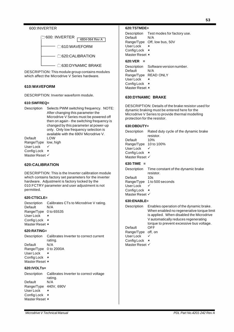
Microdrive V Technical Manual PDL Part No.4201-242 Rev A
53
600:INVERTER
1600: INVERTER
0610:WAVEFORM
0620:CALIBRATION
0630:DYNAMIC BRAKE
4804-064 Rev A
DESCRIPTION: This module group contains moduleswhich affect the Microdrive V Series hardware.
610:WAVEFORM
DESCRIPTION: Inverter waveform module.
610:SWFREQ=Description Selects PWM switching frequency. NOTE:
After changing this parameter theMicrodrive V Series must be powered offthen on again - the switching frequency ischanged by this parameter at power-uponly. Only low frequency selection isavailable with the 690V Microdrive V.
Default LOWRange/Type low, highUser Lock üConfig Lock ûMaster Reset ü
620:CALIBRATION
DESCRIPTION: This is the Inverter calibration modulewhich contains factory set parameters for the inverterhardware. Adjustment is factory locked by the010:FCTRY parameter and user adjustment is notpermitted.
620:CTSCLE=Description Calibrates CTs to Microdrive V rating.Default N/ARange/Type 0 to 65535User Lock ûConfig Lock ûMaster Reset û
620:RATING=Description Calibrates Inverter to correct current
rating.Default N/ARange/Type 0 to 2000AUser Lock ûConfig Lock ûMaster Reset û
620:IVOLTs=
Description Calibrates Inverter to correct voltagerating.
Default N/ARange/Type 440V, 690VUser Lock ûConfig Lock ûMaster Reset û
620:TSTMDE=Description Test modes for factory use.Default N/ARange/Type Off, low bus, 50VUser Lock ûConfig Lock ûMaster Reset û
620:VER =Description Software version number.Default N/ARange/Type READ ONLYUser Lock ûConfig Lock ûMaster Reset û
630:DYNAMIC BRAKE
DESCRIPTION: Details of the brake resistor used fordynamic braking must be entered here for theMicrodrive V Series to provide thermal modellingprotection for the resistor.
630:DBDUTY=Description Rated duty cycle of the dynamic brake
resistor.Default 10%Range/Type 10 to 100%User Lock üConfig Lock ûMaster Reset ü
630:TIME =Description Time constant of the dynamic brake
resistor.Default 10sRange/Type 1 to 500 secondsUser Lock üConfig Lock ûMaster Reset ü
630:ENABLE=Description Enables operation of the dynamic brake.
When enabled no regenerative torque limitis applied. When disabled the MicrodriveV automatically reduces regeneratingtorque to prevent excessive bus voltage.
Default OFFRange/Type off, onUser Lock üConfig Lock ûMaster Reset ü
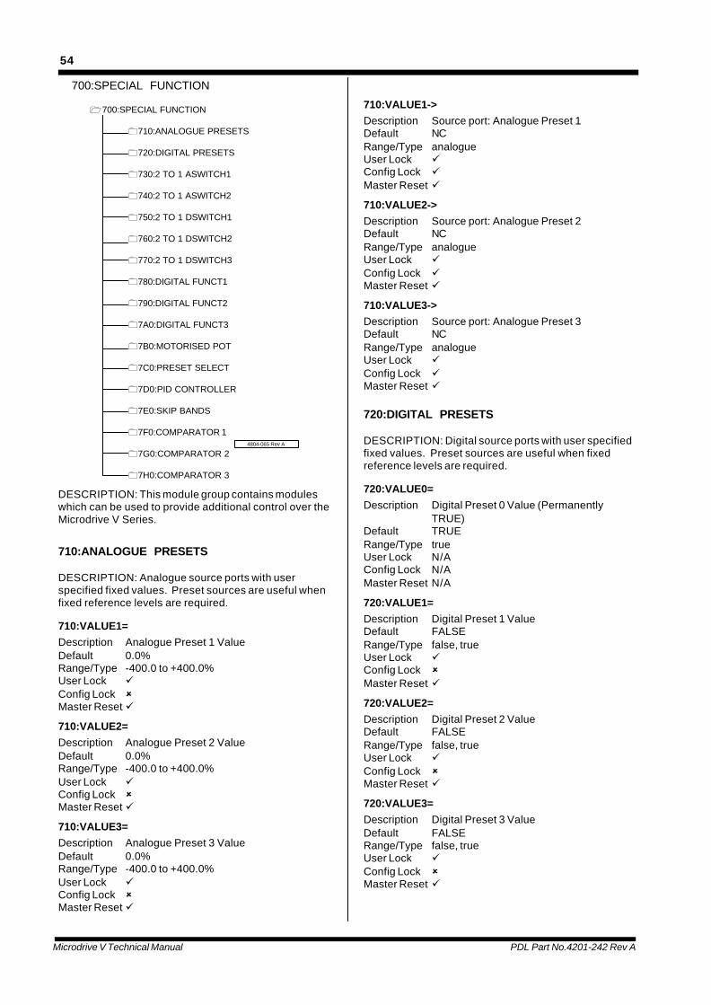
Microdrive V Technical Manual PDL Part No.4201-242 Rev A
54
700:SPECIAL FUNCTION
1700:SPECIAL FUNCTION
0710:ANALOGUE PRESETS
0720:DIGITAL PRESETS
0730:2 TO 1 ASWITCH1
0740:2 TO 1 ASWITCH2
0750:2 TO 1 DSWITCH1
0760:2 TO 1 DSWITCH2
0770:2 TO 1 DSWITCH3
0780:DIGITAL FUNCT1
0790:DIGITAL FUNCT2
07A0:DIGITAL FUNCT3
07B0:MOTORISED POT
07C0:PRESET SELECT
07D0:PID CONTROLLER
07E0:SKIP BANDS
07F0:COMPARATOR 1
07G0:COMPARATOR 2
07H0:COMPARATOR 3
4804-065 Rev A
DESCRIPTION: This module group contains moduleswhich can be used to provide additional control over theMicrodrive V Series.
710:ANALOGUE PRESETS
DESCRIPTION: Analogue source ports with userspecified fixed values. Preset sources are useful whenfixed reference levels are required.
710:VALUE1=Description Analogue Preset 1 ValueDefault 0.0%Range/Type -400.0 to +400.0%User Lock üConfig Lock ûMaster Reset ü
710:VALUE2=Description Analogue Preset 2 ValueDefault 0.0%Range/Type -400.0 to +400.0%User Lock üConfig Lock ûMaster Reset ü
710:VALUE3=Description Analogue Preset 3 ValueDefault 0.0%Range/Type -400.0 to +400.0%User Lock üConfig Lock ûMaster Reset ü
710:VALUE1->Description Source port: Analogue Preset 1Default NCRange/Type analogueUser Lock üConfig Lock üMaster Reset ü
710:VALUE2->Description Source port: Analogue Preset 2Default NCRange/Type analogueUser Lock üConfig Lock üMaster Reset ü
710:VALUE3->Description Source port: Analogue Preset 3Default NCRange/Type analogueUser Lock üConfig Lock üMaster Reset ü
720:DIGITAL PRESETS
DESCRIPTION: Digital source ports with user specifiedfixed values. Preset sources are useful when fixedreference levels are required.
720:VALUE0=Description Digital Preset 0 Value (Permanently
TRUE)Default TRUERange/Type trueUser Lock N/AConfig Lock N/AMaster Reset N/A
720:VALUE1=Description Digital Preset 1 ValueDefault FALSERange/Type false, trueUser Lock üConfig Lock ûMaster Reset ü
720:VALUE2=Description Digital Preset 2 ValueDefault FALSERange/Type false, trueUser Lock üConfig Lock ûMaster Reset ü
720:VALUE3=Description Digital Preset 3 ValueDefault FALSERange/Type false, trueUser Lock üConfig Lock ûMaster Reset ü
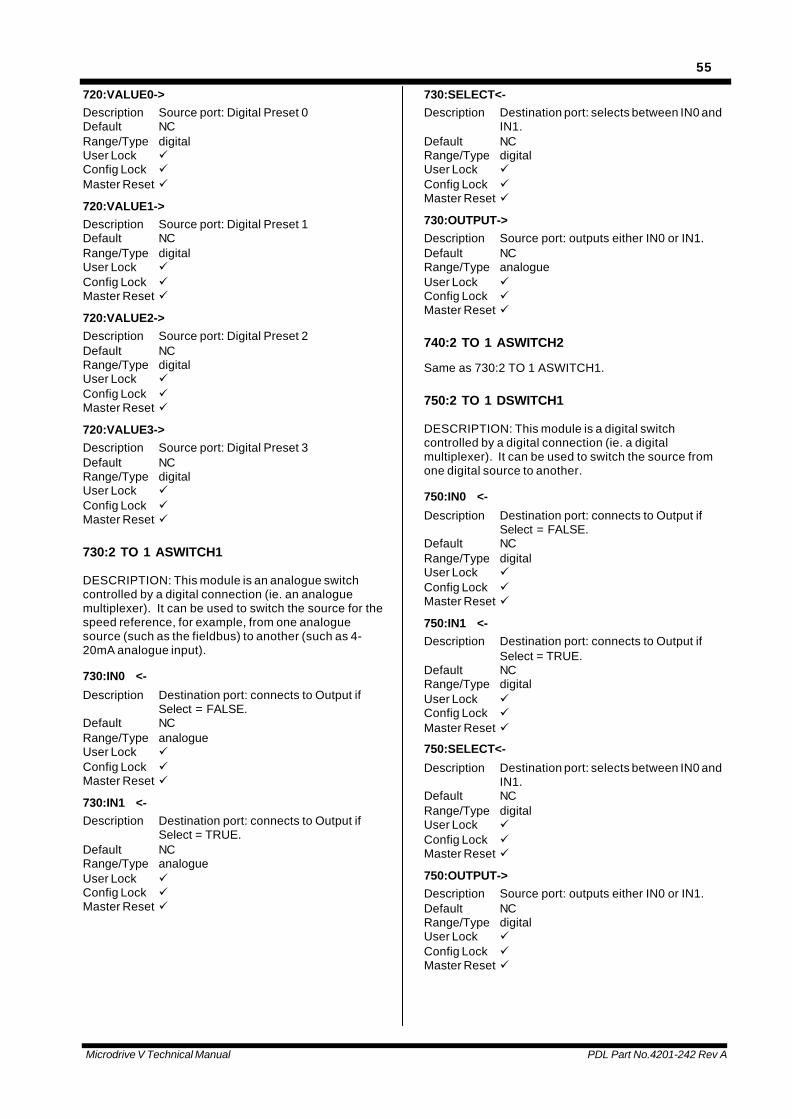
Microdrive V Technical Manual PDL Part No.4201-242 Rev A
55
720:VALUE0->Description Source port: Digital Preset 0Default NCRange/Type digitalUser Lock üConfig Lock üMaster Reset ü
720:VALUE1->Description Source port: Digital Preset 1Default NCRange/Type digitalUser Lock üConfig Lock üMaster Reset ü
720:VALUE2->Description Source port: Digital Preset 2Default NCRange/Type digitalUser Lock üConfig Lock üMaster Reset ü
720:VALUE3->Description Source port: Digital Preset 3Default NCRange/Type digitalUser Lock üConfig Lock üMaster Reset ü
730:2 TO 1 ASWITCH1
DESCRIPTION: This module is an analogue switchcontrolled by a digital connection (ie. an analoguemultiplexer). It can be used to switch the source for thespeed reference, for example, from one analoguesource (such as the fieldbus) to another (such as 4-20mA analogue input).
730:IN0 <-
Description Destination port: connects to Output ifSelect = FALSE.
Default NCRange/Type analogueUser Lock üConfig Lock üMaster Reset ü
730:IN1 <-Description Destination port: connects to Output if
Select = TRUE.Default NCRange/Type analogueUser Lock üConfig Lock üMaster Reset ü
730:SELECT<-Description Destination port: selects between IN0 and
IN1.Default NCRange/Type digitalUser Lock üConfig Lock üMaster Reset ü
730:OUTPUT->Description Source port: outputs either IN0 or IN1.Default NCRange/Type analogueUser Lock üConfig Lock üMaster Reset ü
740:2 TO 1 ASWITCH2
Same as 730:2 TO 1 ASWITCH1.
750:2 TO 1 DSWITCH1
DESCRIPTION: This module is a digital switchcontrolled by a digital connection (ie. a digitalmultiplexer). It can be used to switch the source fromone digital source to another.
750:IN0 <-
Description Destination port: connects to Output ifSelect = FALSE.
Default NCRange/Type digitalUser Lock üConfig Lock üMaster Reset ü
750:IN1 <-Description Destination port: connects to Output if
Select = TRUE.Default NCRange/Type digitalUser Lock üConfig Lock üMaster Reset ü
750:SELECT<-
Description Destination port: selects between IN0 andIN1.
Default NCRange/Type digitalUser Lock üConfig Lock üMaster Reset ü
750:OUTPUT->Description Source port: outputs either IN0 or IN1.Default NCRange/Type digitalUser Lock üConfig Lock üMaster Reset ü
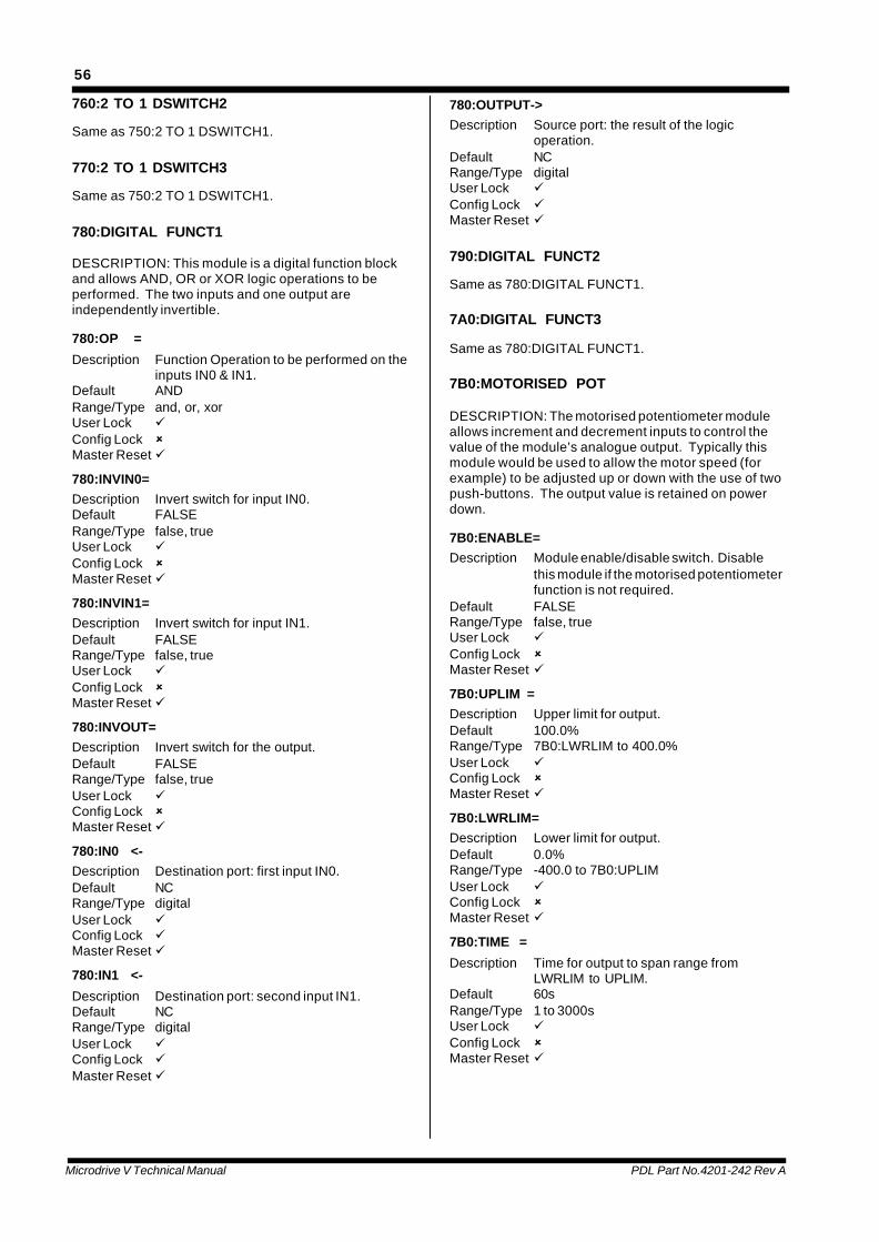
Microdrive V Technical Manual PDL Part No.4201-242 Rev A
56
760:2 TO 1 DSWITCH2
Same as 750:2 TO 1 DSWITCH1.
770:2 TO 1 DSWITCH3
Same as 750:2 TO 1 DSWITCH1.
780:DIGITAL FUNCT1
DESCRIPTION: This module is a digital function blockand allows AND, OR or XOR logic operations to beperformed. The two inputs and one output areindependently invertible.
780:OP =
Description Function Operation to be performed on theinputs IN0 & IN1.
Default ANDRange/Type and, or, xorUser Lock üConfig Lock ûMaster Reset ü
780:INVIN0=Description Invert switch for input IN0.Default FALSERange/Type false, trueUser Lock üConfig Lock ûMaster Reset ü
780:INVIN1=Description Invert switch for input IN1.Default FALSERange/Type false, trueUser Lock üConfig Lock ûMaster Reset ü
780:INVOUT=Description Invert switch for the output.Default FALSERange/Type false, trueUser Lock üConfig Lock ûMaster Reset ü
780:IN0 <-Description Destination port: first input IN0.Default NCRange/Type digitalUser Lock üConfig Lock üMaster Reset ü
780:IN1 <-
Description Destination port: second input IN1.Default NCRange/Type digitalUser Lock üConfig Lock üMaster Reset ü
780:OUTPUT->Description Source port: the result of the logic
operation.Default NCRange/Type digitalUser Lock üConfig Lock üMaster Reset ü
790:DIGITAL FUNCT2
Same as 780:DIGITAL FUNCT1.
7A0:DIGITAL FUNCT3
Same as 780:DIGITAL FUNCT1.
7B0:MOTORISED POT
DESCRIPTION: The motorised potentiometer moduleallows increment and decrement inputs to control thevalue of the module’s analogue output. Typically thismodule would be used to allow the motor speed (forexample) to be adjusted up or down with the use of twopush-buttons. The output value is retained on powerdown.
7B0:ENABLE=Description Module enable/disable switch. Disable
this module if the motorised potentiometerfunction is not required.
Default FALSERange/Type false, trueUser Lock üConfig Lock ûMaster Reset ü
7B0:UPLIM =Description Upper limit for output.Default 100.0%Range/Type 7B0:LWRLIM to 400.0%User Lock üConfig Lock ûMaster Reset ü
7B0:LWRLIM=Description Lower limit for output.Default 0.0%Range/Type -400.0 to 7B0:UPLIMUser Lock üConfig Lock ûMaster Reset ü
7B0:TIME =
Description Time for output to span range fromLWRLIM to UPLIM.
Default 60sRange/Type 1 to 3000sUser Lock üConfig Lock ûMaster Reset ü
Microdrive V Technical Manual PDL Part No.4201-242 Rev A
57
7B0:INC <-Description Destination port: Increase output level.Default NCRange/Type digitalUser Lock üConfig Lock üMaster Reset ü
7B0:DEC <-Description Destination port: Decrease output level.Default NCRange/Type digitalUser Lock üConfig Lock üMaster Reset ü
7B0:OUTPUT->Description Source port: the motorised pot output.Default NCRange/Type analogueUser Lock üConfig Lock üMaster Reset ü
7C0:PRESET SELECT
DESCRIPTION: The preset select module outputs one ofeight user preset values based on thestates of three digital inputs. Typically thismodule would be used to allow the motorspeed (for example) to be selected withthe use of three switches.
7C0:VALUE1=Description Selectable preset value 1, output if SEL0,
SEL1, SEL2=F,F,FDefault 0.0%Range/Type -400.0 to +400.0%User Lock üConfig Lock ûMaster Reset ü
7C0:VALUE2=
Description Selectable preset value 2, output if SEL0,SEL1, SEL2=F,F,T
Default 0.0%Range/Type -400.0 to +400.0%User Lock üConfig Lock ûMaster Reset ü
7C0:VALUE3=Description Selectable preset value 3, output if SEL0,
SEL1, SEL2=F,T,FDefault 0.0%Range/Type -400.0 to +400.0%User Lock üConfig Lock ûMaster Reset ü
7C0:VALUE4=Description Selectable preset value 4, output if SEL0,
SEL1, SEL2=F,T,TDefault 0.0%Range/Type -400.0 to +400.0%User Lock üConfig Lock ûMaster Reset ü
7C0:VALUE5=Description Selectable preset value 5, output if SEL0,
SEL1, SEL2=T,F,FDefault 0.0%Range/Type -400.0 to +400.0%User Lock üConfig Lock ûMaster Reset ü
7C0:VALUE6=Description Selectable preset value 6, output if SEL0,
SEL1, SEL2=T,F,TDefault 0.0%Range/Type -400.0 to +400.0%User Lock üConfig Lock ûMaster Reset ü
7C0:VALUE7=Description Selectable preset value 7, output if SEL0,
SEL1, SEL2=T,T,FDefault 0.0%Range/Type -400.0 to +400.0%User Lock üConfig Lock ûMaster Reset ü
7C0:VALUE8=Description Selectable preset value 8, output if SEL0,
SEL1, SEL2=T,T,TDefault 0.0%Range/Type -400.0 to +400.0%User Lock üConfig Lock ûMaster Reset ü
7C0:SEL0 <-
Description Destination port: Select input 0.Default NCRange/Type digitalUser Lock üConfig Lock üMaster Reset ü
7C0:SEL1 <-
Description Destination port: Select input 1.Default NCRange/Type digitalUser Lock üConfig Lock üMaster Reset ü

Microdrive V Technical Manual PDL Part No.4201-242 Rev A
58
7C0:SEL2 <-Description Destination port: Select input 2.Default NCRange/Type digitalUser Lock üConfig Lock üMaster Reset ü
7C0:OUTPUT->Description Source port: the preset select output.Default NCRange/Type analogueUser Lock üConfig Lock üMaster Reset ü
7D0:PID CONTROLLER
DESCRIPTION: The PID (proportional, integral,derivative) controller module allows the Microdrive VSeries to be used in applications requiring closed loopcontrol. The module also incorporates integrator anti-windup.
7D0:ENABLE=Description Module enable/disable switch. Disable
this module if no PID control is required.Default FALSERange/Type false, trueUser Lock üConfig Lock ûMaster Reset ü
7D0:MODE =Description Control mode: PI or PID controller. For IP
control set KSP (below) to 0.0.Default PIRange/Type PI, PIDUser Lock üConfig Lock ûMaster Reset ü
7D0:KP =Description Proportional gain.Default 1.00Range/Type 0.00 to 16.00User Lock üConfig Lock ûMaster Reset ü
7D0:WITS =Description Product of the integral frequency (wi) and
the sample time (Ts). For an wiTs of 0.1and a 100% error (i.e. ref - feedback), theintegral term will integrate at 10% persample.
Default 0.001Range/Type 0.000 to 0.100User Lock üConfig Lock ûMaster Reset ü
7D0:WDTS =Description Product of the derivative frequency (wd)
and the sample time (Ts). For an wdTs of0.1 and a 10% change per sample in thefeedback signal, the derivative term willequal 100%.
Default 0.10Range/Type 0.01 to 0.10User Lock üConfig Lock ûMaster Reset ü
7D0:UPLIM =
Description Upper level to limit the output.Default 400.0%Range/Type 7D0:LWRLIM to 400.0%User Lock üConfig Lock ûMaster Reset ü
7D0:LWRLIM=Description Lower level to limit the output.Default -400.0%Range/Type -400.0 to 7D0:UPLIMUser Lock üConfig Lock ûMaster Reset ü
7D0:KSP =Description Set-point weighting. Set to 1.0 for PI
control, or 0.0 for IP.Default 1.0Range/Type 0.0 to 1.0User Lock üConfig Lock ûMaster Reset ü
7D0:TS =Description Sample time (Ts) in milliseconds.
Increase Ts for slow processes requiringintegral control.
Default 10msRange/Type 10ms,100ms,1s,10sUser Lock üConfig Lock ûMaster Reset ü
7D0:REF <-Description Destination port: input for the reference
set-point signal.Default NCRange/Type analogueUser Lock üConfig Lock üMaster Reset ü
7D0:F/B <-Description Destination port: input for the feedback
signal. The difference between the REFand F/B signals is the control error whichis output to the ERROR source port .
Default NCRange/Type analogueUser Lock üConfig Lock üMaster Reset ü
Microdrive V Technical Manual PDL Part No.4201-242 Rev A
59
7D0:OFFSET<-Description Destination port: input for offsetting the
PID controller output. Normally this wouldbe the speed reference signal and the PIDcontroller would trim this value beforebeing passed on to the speed referenceinput (220:SPDREF).
Default NCRange/Type analogueUser Lock üConfig Lock üMaster Reset ü
7D0:ENABLE<-Description Destination port: input for disabling the
PID controller output. This has the sameeffect as setting UPLIM and LWRLIM tozero so the OUTPUT value equals theOFFSET input.
Default NCRange/Type digitalUser Lock üConfig Lock üMaster Reset ü
7D0:OUTPUT->Description Source port: the PID controller output +
offset.Default NCRange/Type analogueUser Lock üConfig Lock üMaster Reset ü
7D0:ERROR ->Description Source port: difference between the
reference input (REF) and the feedbackinput (F/B).
Default NCRange/Type analogueUser Lock üConfig Lock üMaster Reset ü
7D0:UPIND ->Description Source port: TRUE when the PID
OUTPUT is being clamped by the upperlimit 7D0:UPLIM.
Default NCRange/Type digitalUser Lock üConfig Lock üMaster Reset ü
7D0:LWRIND->Description Source port: TRUE when the PID
OUTPUT is being clamped by the lowerlimit 7D0:LWRLIM.
Default NCRange/Type digitalUser Lock üConfig Lock üMaster Reset ü
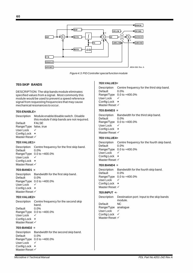
Microdrive V Technical Manual PDL Part No.4201-242 Rev A
60
ERROR
ΣREF+ Σ+
-
d/dt
-Σ
+
OFFSET
UPLIM =
LWRLIM=
OUTPUT
F/B
+ +
+
LWRIND
UPIND
ENABLE
KP =
KSP =
WITS =
WDTS =
TS =
∫
4804-066 Rev A
Figure 4.3: PID Controller special function module
7E0:SKIP BANDS
DESCRIPTION: The skip bands module eliminatesspecified values from a signal. Most commonly thismodule would be used to prevent a speed referencesignal from requesting frequencies that may causemechanical resonances to occur.
7E0:ENABLE=Description Module enable/disable switch. Disable
this module if skip bands are not required.Default FALSERange/Type false, trueUser Lock üConfig Lock ûMaster Reset ü
7E0:VALUE1=
Description Centre frequency for the first skip band.Default 0.0%Range/Type 0.0 to +400.0%User Lock üConfig Lock ûMaster Reset ü
7E0:BAND1 =Description Bandwidth for the first skip band.Default 0.0%Range/Type 0.0 to +400.0%User Lock üConfig Lock ûMaster Reset ü
7E0:VALUE2=Description Centre frequency for the second skip
band.Default 0.0%Range/Type 0.0 to +400.0%User Lock üConfig Lock ûMaster Reset ü
7E0:BAND2 =Description Bandwidth for the second skip band.Default 0.0%Range/Type 0.0 to +400.0%User Lock üConfig Lock ûMaster Reset ü
7E0:VALUE3=Description Centre frequency for the third skip band.Default 0.0%Range/Type 0.0 to +400.0%User Lock üConfig Lock ûMaster Reset ü
7E0:BAND3 =
Description Bandwidth for the third skip band.Default 0.0%Range/Type 0.0 to +400.0%User Lock üConfig Lock ûMaster Reset ü
7E0:VALUE4=Description Centre frequency for the fourth skip band.Default 0.0%Range/Type 0.0 to +400.0%User Lock üConfig Lock ûMaster Reset ü
7E0:BAND4 =Description Bandwidth for the fourth skip band.Default 0.0%Range/Type 0.0 to +400.0%User Lock üConfig Lock ûMaster Reset ü
7E0:INPUT <-Description Destination port: Input to the skip bands
module.Default NCRange/Type analogueUser Lock üConfig Lock üMaster Reset ü
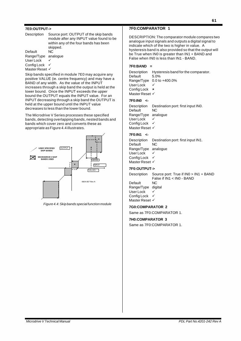
Microdrive V Technical Manual PDL Part No.4201-242 Rev A
61
7E0:OUTPUT->Description Source port: OUTPUT of the skip bands
module after any INPUT value found to bewithin any of the four bands has beenskipped.
Default NCRange/Type analogueUser Lock üConfig Lock üMaster Reset üSkip bands specified in module 7E0 may acquire anypositive VALUE (ie. centre frequency) and may have aBAND of any width. As the value of the INPUTincreases through a skip band the output is held at thelower bound. Once the INPUT exceeds the upperbound the OUTPUT equals the INPUT value. For anINPUT decreasing through a skip band the OUTPUT isheld at the upper bound until the INPUT valuedecreases to less than the lower bound.
The Microdrive V Series processes these specifiedbands, detecting overlapping bands, nested bands andbands which cover zero and converts these asappropriate as Figure 4.4 illustrates.
BAND
VALUE=
INPUT
OUTPUT
MICRODRIVE V SKIPBANDS USED
USER SPECIFIEDSKIP BANDS
4804-067 Rev A
Figure 4.4: Skip bands special function module
7F0:COMPARATOR 1
DESCRIPTION: The comparator module compares twoanalogue input signals and outputs a digital signal toindicate which of the two is higher in value. Ahysteresis band is also provided so that the output willbe True when IN0 is greater than IN1 + BAND andFalse when IN0 is less than IN1 - BAND.
7F0:BAND =
Description Hysteresis band for the comparator.Default 5.0%Range/Type 0.0 to +400.0%User Lock üConfig Lock ûMaster Reset ü
7F0:IN0 <-Description Destination port: first input IN0.Default NCRange/Type analogueUser Lock üConfig Lock üMaster Reset ü
7F0:IN1 <-Description Destination port: first input IN1.Default NCRange/Type analogueUser Lock üConfig Lock üMaster Reset ü
7F0:OUTPUT->Description Source port: True if IN0 > IN1 + BAND
False if IN1 < IN0 - BANDDefault NCRange/Type digitalUser Lock üConfig Lock üMaster Reset ü
7G0:COMPARATOR 2
Same as 7F0:COMPARATOR 1.
7H0:COMPARATOR 3Same as 7F0:COMPARATOR 1.
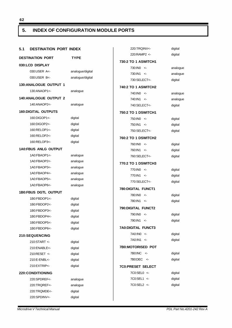
Microdrive V Technical Manual PDL Part No.4201-242 Rev A
62
5. INDEX OF CONFIGURATION MODULE PORTS
5.1 DESTINATION PORT INDEX
DESTINATION PORT TYPE
030:LCD DISPLAY
030:USER A<- analogue/digital
030:USER B<- analogue/digital
130:ANALOGUE OUTPUT 1
130:ANAOP1<- analogue
140:ANALOGUE OUTPUT 2
140:ANAOP2<- analogue
160:DIGITAL OUTPUTS
160:DIGOP1<- digital
160:DIGOP2<- digital
160:RELOP1<- digital
160:RELOP2<- digital
160:RELOP3<- digital
1A0:FBUS ANLG OUTPUT
1A0:FBAOP1<- analogue
1A0:FBAOP2<- analogue
1A0:FBAOP3<- analogue
1A0:FBAOP4<- analogue
1A0:FBAOP5<- analogue
1A0:FBAOP6<- analogue
1B0:FBUS DGTL OUTPUT
1B0:FBDOP1<- digital
1B0:FBDOP2<- digital
1B0:FBDOP3<- digital
1B0:FBDOP4<- digital
1B0:FBDOP5<- digital
1B0:FBDOP6<- digital
210:SEQUENCING
210:START <- digital
210:ENABLE<- digital
210:RESET <- digital
210:E-ENBL<- digital
210:EXTRIP<- digital
220:CONDITIONING
220:SPDREF<- analogue
220:TRQREF<- analogue
220:TRQMDE<- digital
220:SPDINV<- digital
220:TRQINV<- digital
220:RAMP2 <- digital
730:2 TO 1 ASWITCH1
730:IN0 <- analogue
730:IN1 <- analogue
730:SELECT<- digital
740:2 TO 1 ASWITCH2
740:IN0 <- analogue
740:IN1 <- analogue
740:SELECT<- digital
750:2 TO 1 DSWITCH1
750:IN0 <- digital
750:IN1 <- digital
750:SELECT<- digital
760:2 TO 1 DSWITCH2
760:IN0 <- digital
760:IN1 <- digital
760:SELECT<- digital
770:2 TO 1 DSWITCH3
770:IN0 <- digital
770:IN1 <- digital
770:SELECT<- digital
780:DIGITAL FUNCT1
780:IN0 <- digital
780:IN1 <- digital
790:DIGITAL FUNCT2
790:IN0 <- digital
790:IN1 <- digital
7A0:DIGITAL FUNCT3
7A0:IN0 <- digital
7A0:IN1 <- digital
7B0:MOTORISED POT
7B0:INC <- digital
7B0:DEC <- digital
7C0:PRESET SELECT
7C0:SEL0 <- digital
7C0:SEL1 <- digital
7C0:SEL2 <- digital
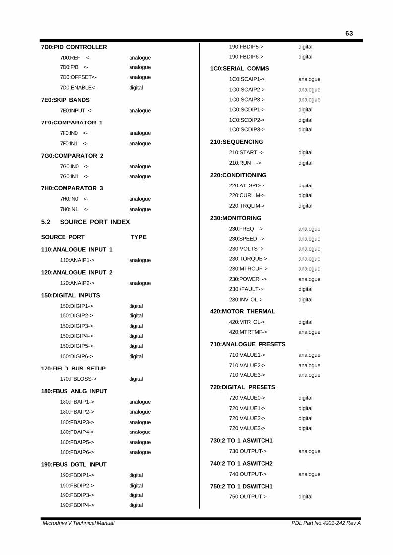
Microdrive V Technical Manual PDL Part No.4201-242 Rev A
63
7D0:PID CONTROLLER
7D0:REF <- analogue
7D0:F/B <- analogue
7D0:OFFSET<- analogue
7D0:ENABLE<- digital
7E0:SKIP BANDS
7E0:INPUT <- analogue
7F0:COMPARATOR 1
7F0:IN0 <- analogue
7F0:IN1 <- analogue
7G0:COMPARATOR 2
7G0:IN0 <- analogue
7G0:IN1 <- analogue
7H0:COMPARATOR 3
7H0:IN0 <- analogue
7H0:IN1 <- analogue
5.2 SOURCE PORT INDEX
SOURCE PORT TYPE
110:ANALOGUE INPUT 1
110:ANAIP1-> analogue
120:ANALOGUE INPUT 2
120:ANAIP2-> analogue
150:DIGITAL INPUTS
150:DIGIP1-> digital
150:DIGIP2-> digital
150:DIGIP3-> digital
150:DIGIP4-> digital
150:DIGIP5-> digital
150:DIGIP6-> digital
170:FIELD BUS SETUP
170:FBLOSS-> digital
180:FBUS ANLG INPUT
180:FBAIP1-> analogue
180:FBAIP2-> analogue
180:FBAIP3-> analogue
180:FBAIP4-> analogue
180:FBAIP5-> analogue
180:FBAIP6-> analogue
190:FBUS DGTL INPUT
190:FBDIP1-> digital
190:FBDIP2-> digital
190:FBDIP3-> digital
190:FBDIP4-> digital
190:FBDIP5-> digital
190:FBDIP6-> digital
1C0:SERIAL COMMS
1C0:SCAIP1-> analogue
1C0:SCAIP2-> analogue
1C0:SCAIP3-> analogue
1C0:SCDIP1-> digital
1C0:SCDIP2-> digital
1C0:SCDIP3-> digital
210:SEQUENCING
210:START -> digital
210:RUN -> digital
220:CONDITIONING
220:AT SPD-> digital
220:CURLIM-> digital
220:TRQLIM-> digital
230:MONITORING
230:FREQ -> analogue
230:SPEED -> analogue
230:VOLTS -> analogue
230:TORQUE-> analogue
230:MTRCUR-> analogue
230:POWER -> analogue
230:/FAULT-> digital
230:INV OL-> digital
420:MOTOR THERMAL
420:MTR OL-> digital
420:MTRTMP-> analogue
710:ANALOGUE PRESETS
710:VALUE1-> analogue
710:VALUE2-> analogue
710:VALUE3-> analogue
720:DIGITAL PRESETS
720:VALUE0-> digital
720:VALUE1-> digital
720:VALUE2-> digital
720:VALUE3-> digital
730:2 TO 1 ASWITCH1
730:OUTPUT-> analogue
740:2 TO 1 ASWITCH2
740:OUTPUT-> analogue
750:2 TO 1 DSWITCH1
750:OUTPUT-> digital
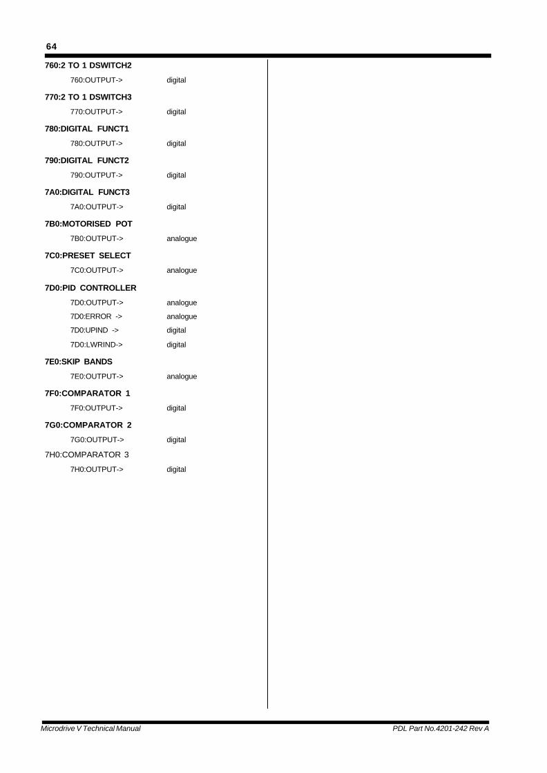
Microdrive V Technical Manual PDL Part No.4201-242 Rev A
64
760:2 TO 1 DSWITCH2
760:OUTPUT-> digital
770:2 TO 1 DSWITCH3
770:OUTPUT-> digital
780:DIGITAL FUNCT1
780:OUTPUT-> digital
790:DIGITAL FUNCT2
790:OUTPUT-> digital
7A0:DIGITAL FUNCT3
7A0:OUTPUT-> digital
7B0:MOTORISED POT
7B0:OUTPUT-> analogue
7C0:PRESET SELECT
7C0:OUTPUT-> analogue
7D0:PID CONTROLLER
7D0:OUTPUT-> analogue
7D0:ERROR -> analogue
7D0:UPIND -> digital
7D0:LWRIND-> digital
7E0:SKIP BANDS
7E0:OUTPUT-> analogue
7F0:COMPARATOR 1
7F0:OUTPUT-> digital
7G0:COMPARATOR 2
7G0:OUTPUT-> digital
7H0:COMPARATOR 3
7H0:OUTPUT-> digital

Microdrive V Technical Manual PDL Part No.4201-242 Rev A
65
6. FORMS
6.1 INTERFACE CONFIGURATION RECORD
Schematic
23
COM
COM
COM
N.O.
N.C.
N.C.
N.O.
N.C.
10k31
3536
N.O.
343332
30
29
26
27
28
24
25
4k7
4k7
4k7
4k7
10
22
21
20
18
19
17
16
15
14
13
11
12
-
9
8
7
6
5
4
+
100
100
250
3
2 +
1 -
250
0 Volts
24 V; 1mA
160 : Relay Output 1
160 : Relay Output 2
160 : Relay Output 3
- Pot. Supply
Encoder SupplyEncoder A+Encoder A-Encoder B+Encoder B-
150 : Digital Output 1
160 : Digital Output 2
+ Pot. Supply
+5V / 100mA
0 Volts
0 Volts
-15V
+15V
0 Volts
0 Volts
4804-008
230 Vac; 1A
24 Vdc; 1A
Suits standard PTC'sor thermostats.
+/- 10 Volts;4-20mA; Zout = 100RMax. Vout = 12Voltstolerance = +/- 2%25mA max. load
24V +/-4V 100mA max.Short circuit protected.
Link terminals 18-19 foractive high.Link terminals 17-18 foractive low.
12Vdc / 24VdcNominal threshold is 6V
+/- 10 Volts;4-20mA; Zin = 250Rtolerance = +/- 2%
0 Volts
+24 Volt / 100mA
+24 Volt / 100mA
Common
150:Digital Input 6
150:Digital Input 5
150:Digital Input 4
150:Digital Input 3
150:Digital Input 2
150:Digital Input 1
PTC I/P
0 Volts
0 Volts
140 : Analogue Output 2
110 : Analogue Input 1
130 : Analogue Output 1
120 : Analogue Input 2+
-
0 Volts
0 Volts
0 Volts
+
-
Title Specifications
Figure 6.1: 36 Terminal Control Board. Refer to Figure 2.6 for the default interface configuration and Figure 1.5 for theinterface specifications and the physical layout of the terminals.
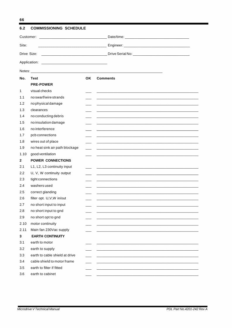
Microdrive V Technical Manual PDL Part No.4201-242 Rev A
66
6.2 COMMISSIONING SCHEDULE
Customer: _________________________________ Date/time: ________________________________
Site: _________________________________ Engineer: _________________________________
Drive Size: _________________________________ Drive Serial No: ____________________________
Application: _________________________________
Notes: __________________________________________________________________
No. Test OK Comments
PRE-POWER
1 visual checks ___ ___________________________________________________
1.1 no swarf/wire strands ___ ___________________________________________________
1.2 no physical damage ___ ___________________________________________________
1.3 clearances ___ ___________________________________________________
1.4 no conducting debris ___ ___________________________________________________
1.5 no insulation damage ___ ___________________________________________________
1.6 no interference ___ ___________________________________________________
1.7 pcb connections ___ ___________________________________________________
1.8 wires out of place ___ ___________________________________________________
1.9 no heat sink air path blockage ___ ___________________________________________________
1.10 good ventilation ___ ___________________________________________________
2 POWER CONNECTIONS
2.1 L1, L2, L3 continuity input ___ ___________________________________________________
2.2 U, V, W continuity output ___ ___________________________________________________
2.3 tight connections ___ ___________________________________________________
2.4 washers used ___ ___________________________________________________
2.5 correct glanding ___ ___________________________________________________
2.6 filter opt. U,V,W in/out ___ ___________________________________________________
2.7 no short input to input ___ ___________________________________________________
2.8 no short input to gnd ___ ___________________________________________________
2.9 no short opt to gnd ___ ___________________________________________________
2.10 motor continuity ___ ___________________________________________________
2.11 Main fan 230Vac supply ___ ___________________________________________________
3 EARTH CONTINUITY
3.1 earth to motor ___ ___________________________________________________
3.2 earth to supply ___ ___________________________________________________
3.3 earth to cable shield at drive ___ ___________________________________________________
3.4 cable shield to motor frame ___ ___________________________________________________
3.5 earth to filter if fitted ___ ___________________________________________________
3.6 earth to cabinet ___ ___________________________________________________

Microdrive V Technical Manual PDL Part No.4201-242 Rev A
67
4 INITIAL POWER UP
4.1 check L1, L2, L3 voltages ___ ___________________________________________________
4.2 main fans blow bulk air at top
rear of each module ___ ___________________________________________________
4.3 power tray fans exhaust at front ___ ___________________________________________________
4.4 EDM filter fans (if used) ___ ___________________________________________________
4.5 free bulk air path ___ ___________________________________________________
5 INITIAL SET UP
5.1 enter motor details ___ ___________________________________________________
5.2 set local speed to zero ___ ___________________________________________________
(020:KBFREQ= 0.0%)
5.3 ensure mode = speed ___ ___________________________________________________
(020:LOCMDE=SPEED)
5.4 select Open Loop ___ ___________________________________________________
(240:CNTRL =OPNLP VEC)
6 INITIAL RUN (NO-LOAD IF POSSIBLE)
6.1 check motor free to rotate
/ no people near ___ ___________________________________________________
6.2 start and check that Microdrive V
and motor run normally ___ ___________________________________________________
6.3 increase speed and check direction___ ___________________________________________________
6.4 run at 5% 10% 25% 50% 100%
(over if required) ___ ___________________________________________________
6.5 check output current (LCD display)
also waveform, level & balance. ___ ___________________________________________________
6.6 check input current waveform
level & balance ___ ___________________________________________________
6.7 check motor noise ___ ___________________________________________________
6.8 check motor vibration ___ ___________________________________________________
6.9 check motor voltage ___ ___________________________________________________
6.10 check motor stability ___ ___________________________________________________
7 AT LOAD
7.1 check input current waveform
level & balance ___ ___________________________________________________
7.2 check output current waveform
level & balance (LCD display) ___ ___________________________________________________
7.3 check EDM filter dc feedback
currents (if used) ___ ___________________________________________________
7.4 run at full load > 10mins ___ ___________________________________________________
7.5 check temperature
(if possible) of connections ___ ___________________________________________________
7.6 check hot start ___ ___________________________________________________
Microdrive V Technical Manual PDL Part No.4201-242 Rev A
68
8 USER SETUP
8.1 set up user connections
and functions as desired ___ ___________________________________________________
8.2 check digital inputs (in local) ___ ___________________________________________________
8.3 check digital outputs ___ ___________________________________________________
8.4 check analogue output scaling ___ ___________________________________________________
8.5 check analogue input scaling ___ ___________________________________________________
8.6 set Microdrive V in remote and
check correct functioning ___ ___________________________________________________
8.7 set up LCD display line ___ ___________________________________________________
8.8 clear any logged faults ___ ___________________________________________________
8.9 set configuration locks ___ ___________________________________________________
8.10 record configuration in manual ___ ___________________________________________________
8.11 test user setup ___ __________________________________________________
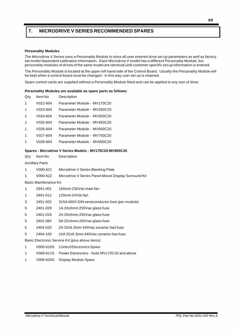
Microdrive V Technical Manual PDL Part No.4201-242 Rev A
69
7. MICRODRIVE V SERIES RECOMMENDED SPARES
Personality Modules
The Microdrive V Series uses a Personality Module to store all user entered drive set up parameters as well as factoryset model dependent calibration information. Each Microdrive V model has a different Personality Module, butpersonality modules of drives of the same model are identical until customer specific set up information is entered.
The Personality Module is located at the upper left hand side of the Control Board. Usually the Personality Module willbe kept when a control board must be changed - in this way user set up is retained.
Spare control cards are supplied without a Personality Module fitted and can be applied to any size of drive.
Personality Modules are available as spare parts as follows:
Qty Item No Description
1 V022-604 Parameter Module - MV170C20
1 V023-604 Parameter Module - MV250C20
1 V024-604 Parameter Module - MV300C20
1 V025-604 Parameter Module - MV450C20
1 V026-604 Parameter Module - MV600C20
1 V027-604 Parameter Module - MV750C20
1 V028-604 Parameter Module - MV900C20
Spares - Microdrive V Series Models - MV170C20-MV900C20
Qty Item No Description
Ancillary Parts
1 V000-621 Microdrive V Series Blanking Plate
1 V000-622 Microdrive V Series Panel Mount Display Surround Kit
Basic Maintenance Kit
1 2941-001 160mm 230Vac main fan
1 2941-012 120mm 24Vdc fan
3 2451-002 315A 660V DIN semiconductor fuse (per module)
5 2401-029 1A 20x5mm 250Vac glass fuse
5 2401-033 2A 20x5mm 250Vac glass fuse
5 2401-060 6A 20x5mm 250Vac glass fuse
5 2404-020 2A 32x6.3mm 440Vac ceramic fast fuse
5 2404-100 10A 32x6.3mm 440Vac ceramic fast fuse
Basic Electronic Service Kit (plus above items)
1 V000-610S Control Electronics Spare
1 V000-611S Power Electronics - Suits MV170C20 and above
1 V000-620S Display Module Spare

Microdrive V Technical Manual PDL Part No.4201-242 Rev A
70
8. MICRODRIVE V SERIES FAN ON/OFF CONTROL
Suggested wiring for applications in which it is desirable to disable the main fans when the Microdrive V Series is notrunning.

Microdrive V Technical Manual PDL Part No.4201-242 Rev A
71
9. AUXILIARY POWER SUPPLY FOR CONTROL ELECTRONICS
The Microdrive V Series control electronics may be powered separately to the main three-phase electronics.
In this case the display and control I/O will remain active in the absence of the main supply. Mains low voltagedetection trip must be disabled set (240:LVTRIP=OFF) to avoid a corresponding trip condition (this is the defaultsetting).
When powered from an auxiliary supply the Microdrive V will accept a start command but will enter a “wait” state. Thisis indicated by the flashing RUN LED on the display module. The Microdrive V will remain in this state until normalsupply voltage is detected or will stop if a disable input is detected.
Sometimes an auxiliary supply may be implemented to permit automatic control of an input isolating contactor. In thiscase the Microdrive V Series start and run digital outputs should be OR’d together to provide a control signal for theinput isolating contactor.
Note: Various other auxilliary supply possibilities exist, (230-440VAC, 350-660VDC) contact supplier.
Microdrive V Technical Manual PDL Part No.4201-242 Rev A
72
10. BEARING FILTERS - PROTECTING MOTOR BEARINGS
Common mode voltages present in the output waveforms of all PWM AC Motor Controllers pose some risk to motorbearings from unintentional flow of electrical current through the bearings (resulting in electrical discharge machining(EDM) of the bearings). Not all motors or installations are affected and it is not always possible to predictsusceptibility, but risks do increase with larger size motors. Though three different mechanisms can be responsible, allrisks can be minimised by appropriate methods, or the use of special common mode (bearing) filters.
Please consult PDL Electronics for futher information.

Microdrive V Technical Manual PDL Part No.4201-242 Rev A
73
11. MAINS HARMONIC REDUCTION
11.1 12 PULSE MICRODRIVE V SERIES OPTION
PDL Electronics Ltd offers standard 12 pulse versions of its Microdrive V Series for harmonic sensitive applications. Asthe 12 pulse conversion requires adaption of the Microdrive V and supply of a special transformer, it is necessary tospecify this option at the time of order.
Figure 11.1 shows the levels of harmonic current and the levels that they are typically reduced to when using the 12pulse system (rated loads and normal system impedances are assumed).
Harmonic6 pulse (typicalMicrodrive V)
MV300C20(full 12 pulse)
MV450C20(partial 12 pulse)
MV600C20(full 12 pulse)
MV750C20(partial 12 pulse)
MV900C20(full 12 pulse)
5th 32% 0% 10.7% 0% 6.2% 0%
7th 10% 0% 3.0% 0% 1.8% 0%
11th 6.1% 5.2% 5.3% 5.2% 5.2% 5.2%
13th 3.4% 3.0% 3.0% 3.0% 2.9% 3.0%
17th 2.4% 0% 1.1% 0% 0.6% 0%
19th 1.9% 0% 0.8% 0% 0.5% 0%
23rd 1.1% 1.4% 1.2% 1.2% 1.2% 1.2%
25th 1.1% 1.1% 1.0% 1.1% 1.1% 1.0%
total THDi* 34% 6% 13% 6% 9% 6%
total THDv** 5.1% 2.0% 2.5% 2.0% 2.2% 2.0%
4804-068 Rev A
Figure 11.1: Harmonic Current Levels in Microdrive V Series 12 Pulse Systems
* impedance balance imperfections between shifted and unshifted portions of the load will increase values recorded aszero (theoretical value), but will typically increase measured THDi by no more than 1%
** estimated for supply capacity twice motor kVA rating, and 5% impedance - this figure may vary markedly accordingto actual supply impedances
11.2 12 PULSE CONVERSION AND INSTALLATION
12 pulse conversion of the Microdrive V Series involves special adaptation of the Microdrive V Series rectifierassembly which is carried out during manufacture. The rectifiers, usually all operating in parallel, are split into twosections. One section is fed via the Microdrive V Series normal (internal) line reactors, the other via a separate phaseshifting transformer. The transformer itself is simply fed from the same supply as the directly fed Microdrive V Seriesinput. In this way, only normal three phase, three wire power and protection is required to be supplied by the user.
The transformer is sized appropriately to the number of Microdrive V Series modules it is driving. Transformer shortcircuit protection is provided by supply protection, while overload protection is achieved through the use of thermalswitches embedded in each phase winding. The switches are normally closed and should be connected into thesystem protection (eg use the Microdrive V Series motor PTC input, allocate a separate stop digital input, or connectthe sensors into a supervisory PLC system).
All six Microdrive V Series supply inputs and transformer connections are insensitive to phase orientation. Refer toFigure 11.3 for further installation details.
Typical transformer details are provided in Figure 11.2. Transformers are unenclosed and intended for switchboardinstallation. They are rated for class H temperature rise with convection cooling to 50 øC maximum ambient. Ensurecooling of the switchboard is adequate for the rated transformer dissipation.
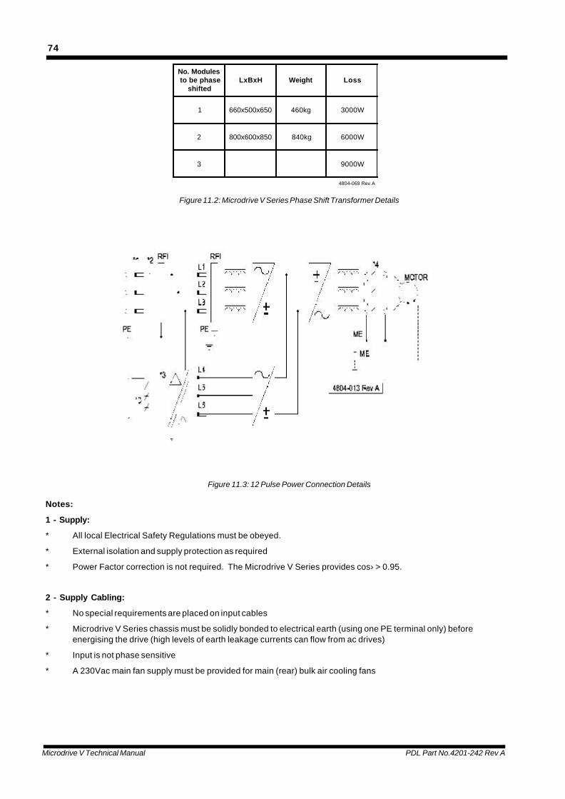
Microdrive V Technical Manual PDL Part No.4201-242 Rev A
74
No. Modules to be phase
shiftedLxBxH Weight Loss
1 660x500x650 460kg 3000W
2 800x600x850 840kg 6000W
3 9000W
4804-069 Rev A
Figure 11.2: Microdrive V Series Phase Shift Transformer Details
Figure 11.3: 12 Pulse Power Connection Details
Notes:
1 - Supply:
* All local Electrical Safety Regulations must be obeyed.
* External isolation and supply protection as required
* Power Factor correction is not required. The Microdrive V Series provides cos› > 0.95.
2 - Supply Cabling:
* No special requirements are placed on input cables
* Microdrive V Series chassis must be solidly bonded to electrical earth (using one PE terminal only) beforeenergising the drive (high levels of earth leakage currents can flow from ac drives)
* Input is not phase sensitive
* A 230Vac main fan supply must be provided for main (rear) bulk air cooling fans

Microdrive V Technical Manual PDL Part No.4201-242 Rev A
75
3 - Special Aspects of 12 Pulse Input:
* Transformer input short circuit protection to be supplied by supply protection.
* Transformer orientation is not phase sensitive
* Do not connect transformer neutral
* Transformer connects to Microdrive V Series inputs L4, L5, L6
* Connect transformer thermal switches to stop drive in event of overload
* Where a RFI suppression capacitor board is supplied separately, this should be connected directly at theswitchboard mains input using short connecting leads
* The transformer shield and transformer frame should be connected together and directly to switchboard chassisbulk earth (as well as board PE)
4 - Output Cabling:
* Output isolation (if required) should only be operated off load (ie with Microdrive V stopped).
* Symmetrical three-cored screened cables are preferred. The cable screen should be solidly bonded to both motorframe and Microdrive V motor earth (ME) terminal only (not anywhere else).
* If motor and load frames are electrically isolated, but electrically connected via shafts, install an isolated couplingin the shafts or bond motor and load using a wide flat (25mm) conductor such as braid or copper foil using theshortest possible connecting route (don’t rely on common earth connections back to switch boards).
* Some regulations may require an earth to be run in addition to using the cable screen. If required this earthshould run externally to the screened cable.
* Power factor correction capacitors must not be connected to Microdrive V Series output.
* If facility for electrical bypass of the motor to mains is required, the Microdrive V Series output must be isolatedfrom the motor first (the Microdrive V Series output must never be connected to mains supply).

Microdrive V Technical Manual PDL Part No.4201-242 Rev A
76
12. CONFIGURATION MODULES QUICK REFERENCE
The following tables which outline the Microdrive V Series parameters relate to drive software version 7.0 or later.
DRIVE SIZE:______________ SERIAL NO.:____________________
SOFTWARE REVISION:________ COMMISSIONING DATE:___________
UPDATED:________________ UPDATED:_____________________
12.1 CONFIGURATION MODULES
1 000:MENU CONFIG
1 010:LOCKS User Default Range/Type
010:CONFIG= _______________________________ LOCK unlock, lock
010:USER = _______________________________ UNLOCK unlock, lock
010:FCTRY = _______________________________ 0.00 0.00 to 655.35
1 020:LOCAL CONTROL User Default Range/Type
020:LOCREM= _______________________________ REMOTE remote, local
020:LOCMDE= _______________________________ SPEED speed, torque
020:KBFREQ= _______________________________ 0.0% -200.0 to +200.0%
020:KBTORQ= _______________________________ 0.0% -300.0 to +300.0%
020:KB S/R= _______________________________ LOC & REM LOC ONLY, LOC & REM
020:EXTS/R= _______________________________ REM ONLY REM ONLY, LOC & REM
1 030:LCD DISPLAY User Default Range/Type
030:LINE2 = _______________________________ CURRENT *
030:LINE3 = _______________________________ SPEED *
030:LINE4 = _______________________________ REF SPEED *
030:USER A<- _______________________________ NC analogue/digital
030:USER B<- _______________________________ NC analogue/digital
1 040:MASTER RESET
040:RESET (ENTER)?
Description
The master reset command will re-initialise drive parameters and connections to factory defaults. Parameters NOTaffected by the master reset are the Microdrive V calibration constants (620:CALIBRATION), the motor nameplate data(410:MOTOR NAMEPLATE) and the local control data (020:LOCAL CONTROL).
* frequency (output, Hz), current (output, A), speed (% synchronous), ref speed (% synchronous), torque (%motor rated), ref torque (% motor rated), bus volts (VDC), output volts (output, Vrms), power (electrical output, kW) ,motor tmp (% motor rated temperature), kWh (kW hours), inv on (Microdrive V on-time, hours), motor run (motor run-time, hours), user A, user B
1 100:INTERFACE
1 110:ANALOGUE INPUT 1 User Default Range/Type
110:TYPE = _______________________________ VOLTAGE voltage, current
110:LOW = _______________________________ 0% -400 to +400%
110:HIGH = _______________________________ 100% -400 to +400%
110:ANAIP1-> _______________________________ 220SPDREF analogue
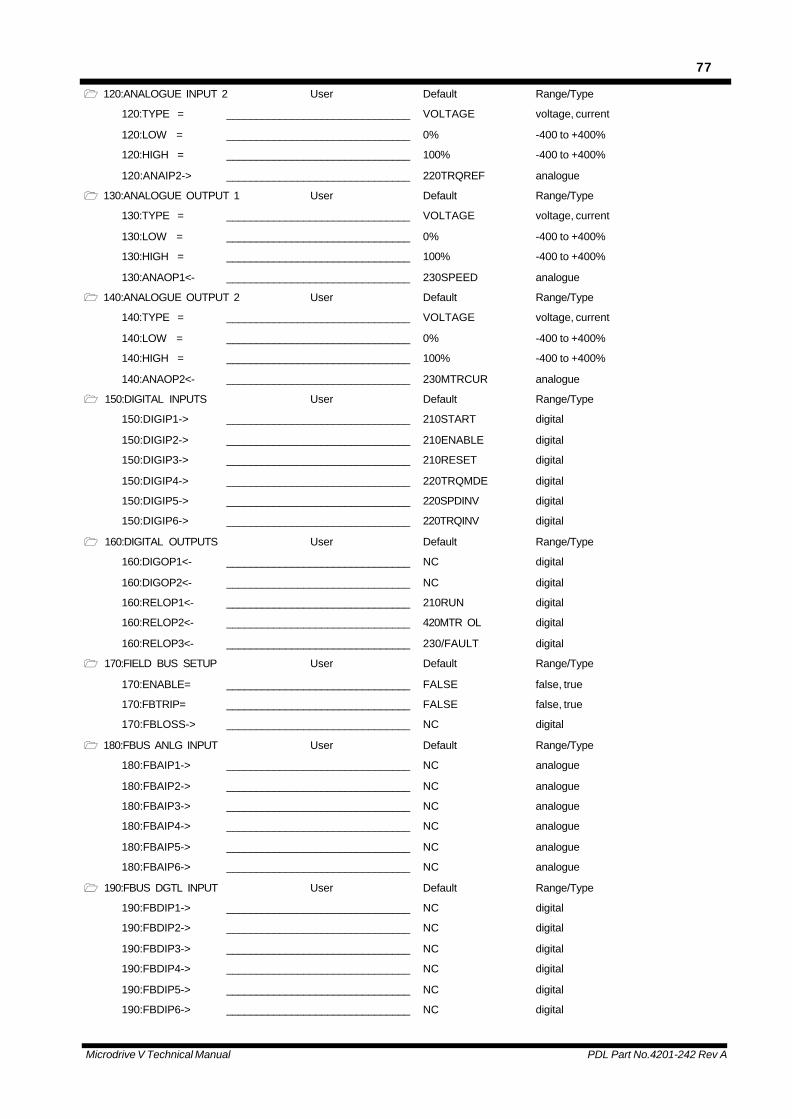
Microdrive V Technical Manual PDL Part No.4201-242 Rev A
77
1 120:ANALOGUE INPUT 2 User Default Range/Type
120:TYPE = _______________________________ VOLTAGE voltage, current
120:LOW = _______________________________ 0% -400 to +400%
120:HIGH = _______________________________ 100% -400 to +400%
120:ANAIP2-> _______________________________ 220TRQREF analogue
1 130:ANALOGUE OUTPUT 1 User Default Range/Type
130:TYPE = _______________________________ VOLTAGE voltage, current
130:LOW = _______________________________ 0% -400 to +400%
130:HIGH = _______________________________ 100% -400 to +400%
130:ANAOP1<- _______________________________ 230SPEED analogue
1 140:ANALOGUE OUTPUT 2 User Default Range/Type
140:TYPE = _______________________________ VOLTAGE voltage, current
140:LOW = _______________________________ 0% -400 to +400%
140:HIGH = _______________________________ 100% -400 to +400%
140:ANAOP2<- _______________________________ 230MTRCUR analogue
1 150:DIGITAL INPUTS User Default Range/Type
150:DIGIP1-> _______________________________ 210START digital
150:DIGIP2-> _______________________________ 210ENABLE digital
150:DIGIP3-> _______________________________ 210RESET digital
150:DIGIP4-> _______________________________ 220TRQMDE digital
150:DIGIP5-> _______________________________ 220SPDINV digital
150:DIGIP6-> _______________________________ 220TRQINV digital
1 160:DIGITAL OUTPUTS User Default Range/Type
160:DIGOP1<- _______________________________ NC digital
160:DIGOP2<- _______________________________ NC digital
160:RELOP1<- _______________________________ 210RUN digital
160:RELOP2<- _______________________________ 420MTR OL digital
160:RELOP3<- _______________________________ 230/FAULT digital
1 170:FIELD BUS SETUP User Default Range/Type
170:ENABLE= _______________________________ FALSE false, true
170:FBTRIP= _______________________________ FALSE false, true
170:FBLOSS-> _______________________________ NC digital
1 180:FBUS ANLG INPUT User Default Range/Type
180:FBAIP1-> _______________________________ NC analogue
180:FBAIP2-> _______________________________ NC analogue
180:FBAIP3-> _______________________________ NC analogue
180:FBAIP4-> _______________________________ NC analogue
180:FBAIP5-> _______________________________ NC analogue
180:FBAIP6-> _______________________________ NC analogue
1 190:FBUS DGTL INPUT User Default Range/Type
190:FBDIP1-> _______________________________ NC digital
190:FBDIP2-> _______________________________ NC digital
190:FBDIP3-> _______________________________ NC digital
190:FBDIP4-> _______________________________ NC digital
190:FBDIP5-> _______________________________ NC digital
190:FBDIP6-> _______________________________ NC digital
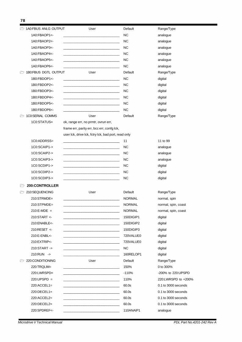
Microdrive V Technical Manual PDL Part No.4201-242 Rev A
78
1 1A0:FBUS ANLG OUTPUT User Default Range/Type
1A0:FBAOP1<- _______________________________ NC analogue
1A0:FBAOP2<- _______________________________ NC analogue
1A0:FBAOP3<- _______________________________ NC analogue
1A0:FBAOP4<- _______________________________ NC analogue
1A0:FBAOP5<- _______________________________ NC analogue
1A0:FBAOP6<- _______________________________ NC analogue
1 1B0:FBUS DGTL OUTPUT User Default Range/Type
1B0:FBDOP1<- _______________________________ NC digital
1B0:FBDOP2<- _______________________________ NC digital
1B0:FBDOP3<- _______________________________ NC digital
1B0:FBDOP4<- _______________________________ NC digital
1B0:FBDOP5<- _______________________________ NC digital
1B0:FBDOP6<- _______________________________ NC digital
1 1C0:SERIAL COMMS User Default Range/Type
1C0:STATUS= ok, range err, no prmtr, ovrun err,
frame err, parity err, bcc err, confg lck,
user lck, drive lck, fctry lck, bad port, read only
1C0:ADDRSS= _______________________________ 11 11 to 99
1C0:SCAIP1-> _______________________________ NC analogue
1C0:SCAIP2-> _______________________________ NC analogue
1C0:SCAIP3-> _______________________________ NC analogue
1C0:SCDIP1-> _______________________________ NC digital
1C0:SCDIP2-> _______________________________ NC digital
1C0:SCDIP3-> _______________________________ NC digital
1 200:CONTROLLER
1 210:SEQUENCING User Default Range/Type
210:STRMDE= _______________________________ NORMAL normal, spin
210:STPMDE= _______________________________ NORMAL normal, spin, coast
210:E-MDE = _______________________________ NORMAL normal, spin, coast
210:START <- _______________________________ 150DIGIP1 digital
210:ENABLE<- _______________________________ 150DIGIP2 digital
210:RESET <- _______________________________ 150DIGIP3 digital
210:E-ENBL<- _______________________________ 720VALUE0 digital
210:EXTRIP<- _______________________________ 720VALUE0 digital
210:START -> _______________________________ NC digital
210:RUN -> _______________________________ 160RELOP1 digital
1 220:CONDITIONING User Default Range/Type
220:TRQLIM= _______________________________ 150% 0 to 300%
220:LWRSPD= _______________________________ -110% -200% to 220:UPSPD
220:UPSPD = _______________________________ 110% 220:LWRSPD to +200%
220:ACCEL1= _______________________________ 60.0s 0.1 to 3000 seconds
220:DECEL1= _______________________________ 60.0s 0.1 to 3000 seconds
220:ACCEL2= _______________________________ 60.0s 0.1 to 3000 seconds
220:DECEL2= _______________________________ 60.0s 0.1 to 3000 seconds
220:SPDREF<- _______________________________ 110ANAIP1 analogue
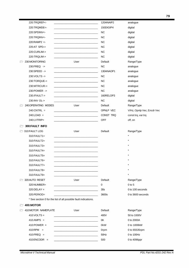
Microdrive V Technical Manual PDL Part No.4201-242 Rev A
79
220:TRQREF<- _______________________________ 120ANAIP2 analogue
220:TRQMDE<- _______________________________ 150DIGIP4 digital
220:SPDINV<- _______________________________ NC digital
220:TRQINV<- _______________________________ NC digital
220:RAMP2 <- _______________________________ NC digital
220:AT SPD-> _______________________________ NC digital
220:CURLIM-> _______________________________ NC digital
220:TRQLIM-> _______________________________ NC digital
1 230:MONITORING User Default Range/Type
230:FREQ -> _______________________________ NC analogue
230:SPEED -> _______________________________ 130ANAOP1 analogue
230:VOLTS -> _______________________________ NC analogue
230:TORQUE-> _______________________________ NC analogue
230:MTRCUR-> _______________________________ NC analogue
230:POWER -> _______________________________ NC analogue
230:/FAULT-> _______________________________ 160RELOP3 digital
230:INV OL-> _______________________________ NC digital
1 240:OPERATING MODES User Default Range/Type
240:CNTRL = _______________________________ OPNLP VEC V/Hz, Opnlp Vec, Encdr Vec
240:LOAD = _______________________________ CONST TRQ const trq, var trq
240:LVTRIP= _______________________________ OFF off, on
1 300:FAULT INFO
1 310:FAULT LOG User Default Range/Type
310:FAULT1= _______________________________ *
310:FAULT2= _______________________________ *
310:FAULT3= _______________________________ *
310:FAULT4= _______________________________ *
310:FAULT5= _______________________________ *
310:FAULT6= _______________________________ *
310:FAULT7= _______________________________ *
310:FAULT8= _______________________________ *
310:FAULT9= _______________________________ *
1 320:AUTO RESET User Default Range/Type
320:NUMBER= _______________________________ 0 0 to 5
320:DELAY = _______________________________ 30s 0 to 100 seconds
320:PERIOD= _______________________________ 3600s 0 to 3600 seconds
* See section 0 for the list of all possible fault indications.
1 400:MOTOR
1 410:MOTOR NAMEPLATE User Default Range/Type
410:VOLTS = _______________________________ 400V 50 to 1000V
410:AMPS = _______________________________ 0A 0 to 2000A
410:POWER = _______________________________ 0kW 0 to 1000kW
410:RPM = _______________________________ 0rpm 0 to 65535rpm
410:FREQ = _______________________________ 50Hz 0 to 100Hz
410:ENCODR = _______________________________ 500 0 to 4096ppr

Microdrive V Technical Manual PDL Part No.4201-242 Rev A
80
1 420:MOTOR THERMAL User Default Range/Type
420:F COOL= _______________________________ OFF off, on
420:STRTIM= _______________________________ 10.0s 0 to 60seconds
420:TRIP = _______________________________ ON off, on
420:RR ADJ= _______________________________ OFF off, on
420:MTR OL-> _______________________________ 160RELOP2 digital
420:MTRTMP-> _______________________________ NC analogue
1 430:MOTOR MODEL User Default Range/Type
430:RS = _______________________________ 1.0% 0 to 10.0%
430:RR = _______________________________ 1.0% 0 to 10.0%
430:IMAG = _______________________________ 50.0% 0 to 150.0%
430:LKG = _______________________________ 10.0% 0 to 150.0%
1 500:VECTOR CONTROL
1 510:SETTINGS User Default Range/Type
510:BSTMDE= _______________________________ OFF off, on
510:IBOOST= _______________________________ 0% 0 to +250%
510:J COMP= _______________________________ 0.0s 0 to 100 seconds
510:FWK PT= _______________________________ 120% 80 to 150%
510:ADAPT= _______________________________ OFF off, on
1 520:GAINS User Default Range/Type
520:WLPKP = _______________________________ 16000 0 to 32767
520:WLPKI = _______________________________ 20 20 to 32767
520:WLPKD = _______________________________ 0 0 to 32767
520:PHLPKP= _______________________________ 10000 0 to 32767
520:FRLPKP= _______________________________ 3000 0 to 32767
520:FRLPKI= _______________________________ 800 20 to 32767
520:ILPKP = _______________________________ 2000 0 to 32767
520:ILPKI = _______________________________ 400 20 to 32767
1 600:MICRODRIVE V
1 610:WAVEFORM User Default Range/Type
610:SWFREQ= _______________________________ LOW low, high
1 620:CALIBRATION User Default Range/Type
620:CTSCLE= _______________________________ N/A 0 to 65535
620:RATING= _______________________________ N/A 0 to 2000A
620:IVOLTS= _______________________________ N/A 440V, 690V
620:TSTMDE= _______________________________ N/A off, low bus, 50V
620:VER = _______________________________ N/A READ ONLY
1 630:DYNAMIC BRAKE User Default Range/Type
630:DBDUTY= _______________________________ 10% 10 to 100%
630:TIME = _______________________________ 10s 1 to 500 seconds
630:ENABLE= _______________________________ OFF off, on
1 700:SPECIAL FUNCTION
1 710:ANALOGUE PRESETS User Default Range/Type
710:VALUE1= _______________________________ 0.0% -400.0 to +400.0%
710:VALUE2= _______________________________ 0.0% -400.0 to +400.0%
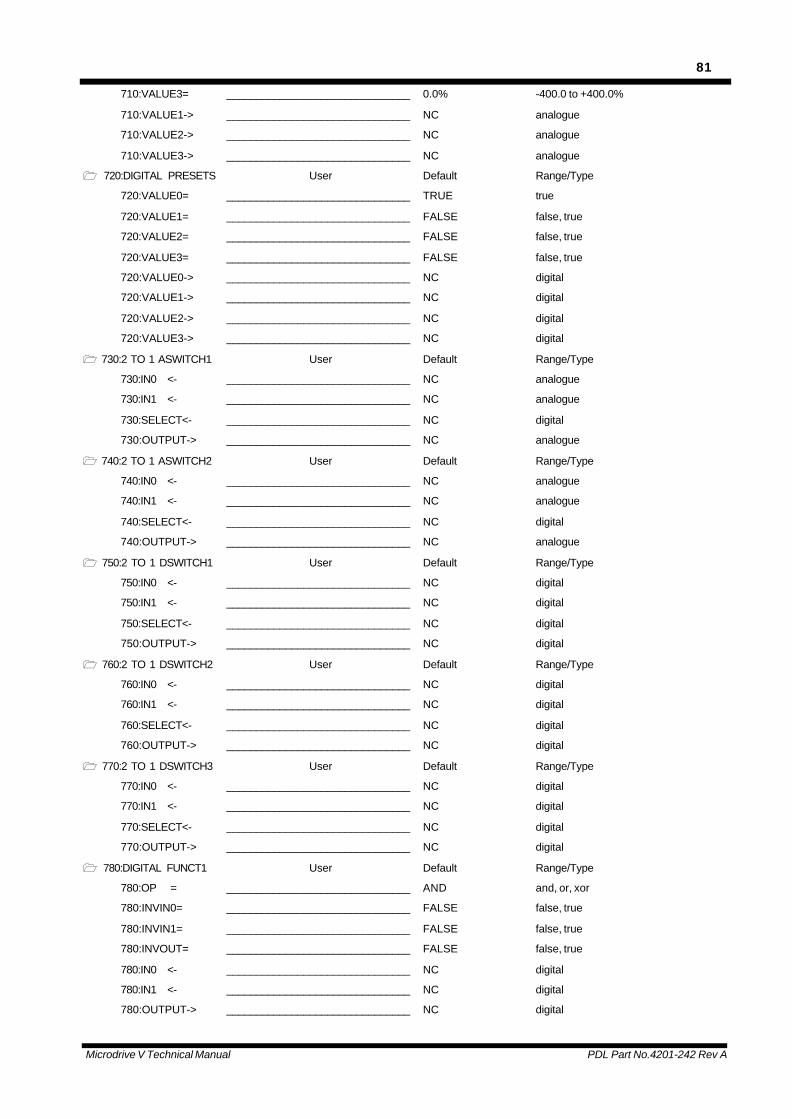
Microdrive V Technical Manual PDL Part No.4201-242 Rev A
81
710:VALUE3= _______________________________ 0.0% -400.0 to +400.0%
710:VALUE1-> _______________________________ NC analogue
710:VALUE2-> _______________________________ NC analogue
710:VALUE3-> _______________________________ NC analogue
1 720:DIGITAL PRESETS User Default Range/Type
720:VALUE0= _______________________________ TRUE true
720:VALUE1= _______________________________ FALSE false, true
720:VALUE2= _______________________________ FALSE false, true
720:VALUE3= _______________________________ FALSE false, true
720:VALUE0-> _______________________________ NC digital
720:VALUE1-> _______________________________ NC digital
720:VALUE2-> _______________________________ NC digital
720:VALUE3-> _______________________________ NC digital
1 730:2 TO 1 ASWITCH1 User Default Range/Type
730:IN0 <- _______________________________ NC analogue
730:IN1 <- _______________________________ NC analogue
730:SELECT<- _______________________________ NC digital
730:OUTPUT-> _______________________________ NC analogue
1 740:2 TO 1 ASWITCH2 User Default Range/Type
740:IN0 <- _______________________________ NC analogue
740:IN1 <- _______________________________ NC analogue
740:SELECT<- _______________________________ NC digital
740:OUTPUT-> _______________________________ NC analogue
1 750:2 TO 1 DSWITCH1 User Default Range/Type
750:IN0 <- _______________________________ NC digital
750:IN1 <- _______________________________ NC digital
750:SELECT<- _______________________________ NC digital
750:OUTPUT-> _______________________________ NC digital
1 760:2 TO 1 DSWITCH2 User Default Range/Type
760:IN0 <- _______________________________ NC digital
760:IN1 <- _______________________________ NC digital
760:SELECT<- _______________________________ NC digital
760:OUTPUT-> _______________________________ NC digital
1 770:2 TO 1 DSWITCH3 User Default Range/Type
770:IN0 <- _______________________________ NC digital
770:IN1 <- _______________________________ NC digital
770:SELECT<- _______________________________ NC digital
770:OUTPUT-> _______________________________ NC digital
1 780:DIGITAL FUNCT1 User Default Range/Type
780:OP = _______________________________ AND and, or, xor
780:INVIN0= _______________________________ FALSE false, true
780:INVIN1= _______________________________ FALSE false, true
780:INVOUT= _______________________________ FALSE false, true
780:IN0 <- _______________________________ NC digital
780:IN1 <- _______________________________ NC digital
780:OUTPUT-> _______________________________ NC digital
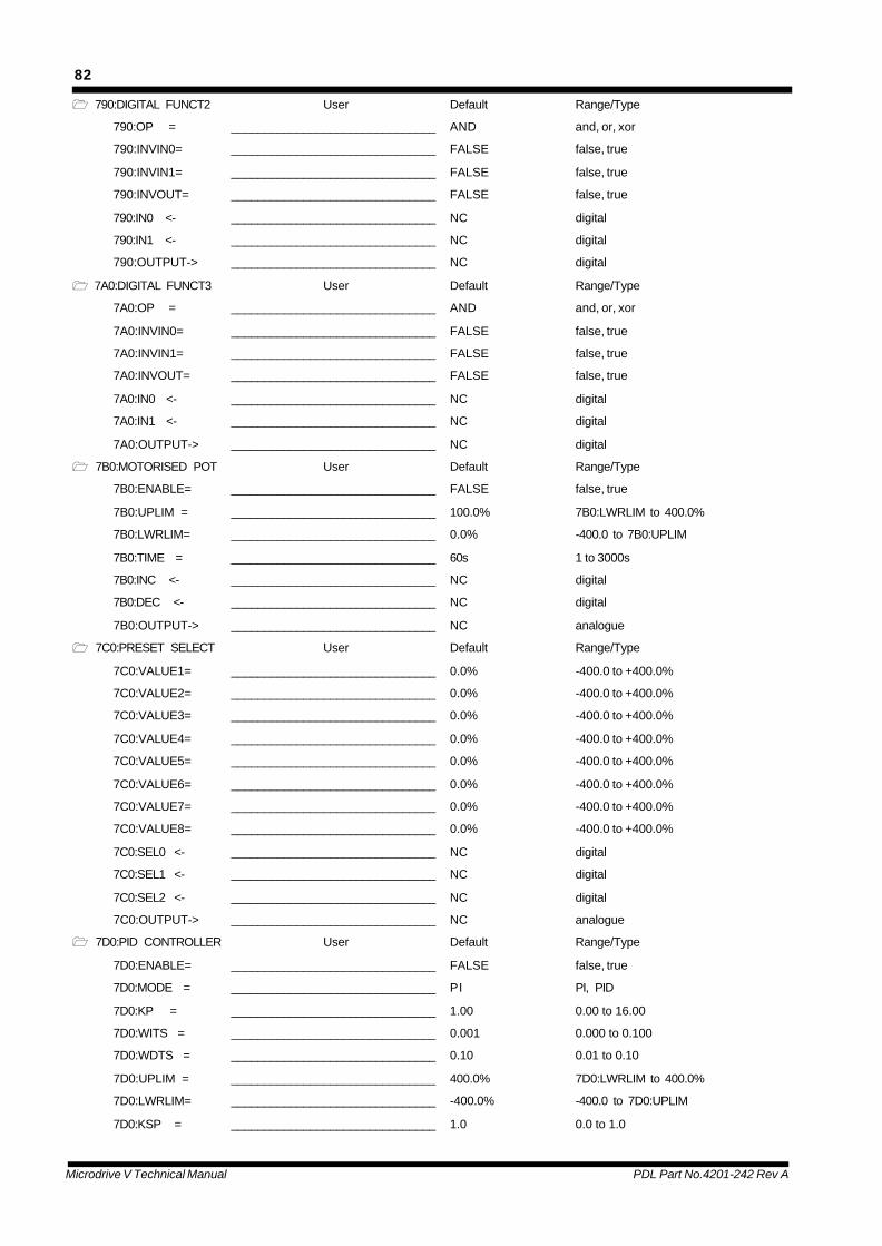
Microdrive V Technical Manual PDL Part No.4201-242 Rev A
82
1 790:DIGITAL FUNCT2 User Default Range/Type
790:OP = _______________________________ AND and, or, xor
790:INVIN0= _______________________________ FALSE false, true
790:INVIN1= _______________________________ FALSE false, true
790:INVOUT= _______________________________ FALSE false, true
790:IN0 <- _______________________________ NC digital
790:IN1 <- _______________________________ NC digital
790:OUTPUT-> _______________________________ NC digital
1 7A0:DIGITAL FUNCT3 User Default Range/Type
7A0:OP = _______________________________ AND and, or, xor
7A0:INVIN0= _______________________________ FALSE false, true
7A0:INVIN1= _______________________________ FALSE false, true
7A0:INVOUT= _______________________________ FALSE false, true
7A0:IN0 <- _______________________________ NC digital
7A0:IN1 <- _______________________________ NC digital
7A0:OUTPUT-> _______________________________ NC digital
1 7B0:MOTORISED POT User Default Range/Type
7B0:ENABLE= _______________________________ FALSE false, true
7B0:UPLIM = _______________________________ 100.0% 7B0:LWRLIM to 400.0%
7B0:LWRLIM= _______________________________ 0.0% -400.0 to 7B0:UPLIM
7B0:TIME = _______________________________ 60s 1 to 3000s
7B0:INC <- _______________________________ NC digital
7B0:DEC <- _______________________________ NC digital
7B0:OUTPUT-> _______________________________ NC analogue
1 7C0:PRESET SELECT User Default Range/Type
7C0:VALUE1= _______________________________ 0.0% -400.0 to +400.0%
7C0:VALUE2= _______________________________ 0.0% -400.0 to +400.0%
7C0:VALUE3= _______________________________ 0.0% -400.0 to +400.0%
7C0:VALUE4= _______________________________ 0.0% -400.0 to +400.0%
7C0:VALUE5= _______________________________ 0.0% -400.0 to +400.0%
7C0:VALUE6= _______________________________ 0.0% -400.0 to +400.0%
7C0:VALUE7= _______________________________ 0.0% -400.0 to +400.0%
7C0:VALUE8= _______________________________ 0.0% -400.0 to +400.0%
7C0:SEL0 <- _______________________________ NC digital
7C0:SEL1 <- _______________________________ NC digital
7C0:SEL2 <- _______________________________ NC digital
7C0:OUTPUT-> _______________________________ NC analogue
1 7D0:PID CONTROLLER User Default Range/Type
7D0:ENABLE= _______________________________ FALSE false, true
7D0:MODE = _______________________________ PI PI, PID
7D0:KP = _______________________________ 1.00 0.00 to 16.00
7D0:WITS = _______________________________ 0.001 0.000 to 0.100
7D0:WDTS = _______________________________ 0.10 0.01 to 0.10
7D0:UPLIM = _______________________________ 400.0% 7D0:LWRLIM to 400.0%
7D0:LWRLIM= _______________________________ -400.0% -400.0 to 7D0:UPLIM
7D0:KSP = _______________________________ 1.0 0.0 to 1.0

Microdrive V Technical Manual PDL Part No.4201-242 Rev A
83
7D0:TS = _______________________________ 10ms 10ms,100ms,1s,10s
7D0:REF <- _______________________________ NC analogue
7D0:F/B <- _______________________________ NC analogue
7D0:OFFSET<- _______________________________ NC analogue
7D0:ENABLE<- _______________________________ NC digital
7D0:OUTPUT-> _______________________________ NC analogue
7D0:ERROR -> _______________________________ NC analogue
7D0:UPIND -> _______________________________ NC digital
7D0:LWRIND-> _______________________________ NC digital
1 7E0:SKIP BANDS User Default Range/Type
7E0:ENABLE= _______________________________ FALSE false, true
7E0:VALUE1= _______________________________ 0.0% 0.0 to +400.0%
7E0:BAND1 = _______________________________ 0.0% 0.0 to +400.0%
7E0:VALUE2= _______________________________ 0.0% 0.0 to +400.0%
7E0:BAND2 = _______________________________ 0.0% 0.0 to +400.0%
7E0:VALUE3= _______________________________ 0.0% 0.0 to +400.0%
7E0:BAND3 = _______________________________ 0.0% 0.0 to +400.0%
7E0:VALUE4= _______________________________ 0.0% 0.0 to +400.0%
7E0:BAND4 = _______________________________ 0.0% 0.0 to +400.0%
7E0:INPUT <- _______________________________ NC analogue
7E0:OUTPUT-> _______________________________ NC analogue
1 7F0:COMPARATOR 1 User Default Range/Type
7F0:BAND = _______________________________ 5.0% 0.0 to +400.0%
7F0:IN0 <- _______________________________ NC analogue
7F0:IN1 <- _______________________________ NC analogue
7F0:OUTPUT-> _______________________________ NC digital
1 7G0:COMPARATOR 2 User Default Range/Type
7G0:BAND = _______________________________ 5.0% 0.0 to +400.0%
7G0:IN0 <- _______________________________ NC analogue
7G0:IN1 <- _______________________________ NC analogue
7G0:OUTPUT-> _______________________________ NC digital
1 7H0:COMPARATOR 3 User Default Range/Type
7H0:BAND = _______________________________ 5.0% 0.0 to +400.0%
7H0:IN0 <- _______________________________ NC analogue
7H0:IN1 <- _______________________________ NC analogue
7H0:OUTPUT-> _______________________________ NC digital
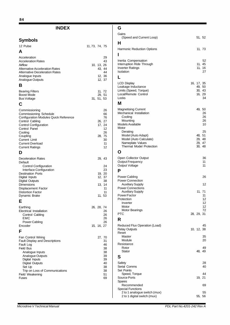
Microdrive V Technical Manual PDL Part No.4201-242 Rev A
84
INDEX
Symbols12 Pulse 11, 73, 74, 75
AAcceleration 29Acceleration Rates 43Airflow 10, 13, 26Alternative Acceleration Rates 43, 44Alternative Deceleration Rates 44Analogue Inputs 12, 36Analogue Outputs 12, 37
BBearing Filters 11, 72Boost Mode 29, 51Bus Voltage 31, 51, 53
CCommissioning 26Commissioning Schedule 66Configuration Modules Quick Reference 76Control Cabling 26, 27Control Configuration 17, 24Control Panel 12Cooling 26Coupling 28, 75Current Limit 30Current Overload 11Current Ratings 12
DDeceleration Rates 29, 43Default
Control Configuration 24Interface Configuration 23
Destination Ports 19, 20Digital Inputs 12, 37Digital Outputs 38Dimensions 13, 14Displacement Factor 11Distortion Factor 11Dynamic Brake 11, 53
EEarthing 26, 28, 74Electrical Installation 26
Control Cabling 26EMC 26Power Cabling 26
Encoder 15, 16, 27
FFan Control Wiring 27, 70Fault Display and Descriptions 31Fault Log 46Field Bus 38
Analogue Inputs 38Analogue Outputs 39Digital Inputs 39Digital Outputs 40Set Up 38Trip on Loss of Communications 38
Field Weakening 51Fuses 69
GGains
(Speed and Current Loop) 51, 52
HHarmonic Reduction Options 11, 73
IInertia Compensation 52Interruption Ride Through 11, 45Inverter Ratings 11, 16Isolation 27
LLCD Display 16, 17, 35Leakage Inductance 49, 50Limits (Speed, Torque) 30, 43Local/Remote Control 16, 29Locks 34
MMagnetising Current 49, 50Mechanical Installation 26
Cooling 26Mounting 26
Models Available 10Motor
Derating 25Model (Auto Adapt) 48, 51Model (Auto Calculate) 29, 48Nameplate Values 29, 47Thermal Model Protection 30, 48
OOpen Collector Output 36Output Frequency 11Output Voltage 11
PPower Cabling 26Power Connection
Auxiliary Supply 12Power Connections
Auxiliary Supply 11, 71Power Factor 11Protection 12
Inverter 12Motor 12Motor Bearings 72
PTC 28, 29, 31
RReduced Flux Operation (Load) 45Relay Outputs 10, 12, 38Reset
Master 35Module 20
ResistanceRotor 49Stator 48, 49
SSafety 28Serial Comms 40Set Points
Speed, Torque 44Source Ports 19, 21Spares
Recommended 69Special Functions
2 to 1 analogue switch (mux) 552 to 1 digital switch (mux) 55, 56

Microdrive V Technical Manual PDL Part No.4201-242 Rev A
85
Specifications are subject to change without notice.
Distributed by:
4880-012 Rev H
Manufactured by:
Head Office: 81 Austin Street, Napier, New Zealand.Tel: +64-6-843-5855 Fax: +64-6-843-5185Sales branch offices in Auckland and Christchurch.FREEPHONE: 0800-PDL-HELP (0800-735-4357 New Zealand only)Email: [email protected]: www.pdl.co.nz
Germany: Nuremberg Tel: +49-9128-91990 Fax: +49-9128-91998024 Hour Hotline: 0171-8530-649 (Germany only)Internet: www.pdl-europe.com
Australia: Customer Service Hotline: 1800-644-677 (Australia only)
Comparators 61digital functions (AND, OR, XOR) 56Motorised potentiometer 56PID Controller 58Preset select (switched speed) 57Presets 54Skip Bands 60, 61
Special Options 11Speed Control Mode 34, 44Standard Configuration 28Standards 11Start and Stop Modes 42, 43Start Up 29Start/Stop/Reset Signals 41, 42Status Indication 17Switching Frequency 11, 16, 53
TTerminals (wiring) 15Thermal Model 31Thermal Model Protection 31Torque Control Mode 35, 45
VV/Hz Mode 16, 45Vector Control 10Vectorque
Closed Loop Vector (Encoder Mode) 16, 30, 45Open Loop Vector (Sensorless Vector) 16, 29, 45, 48
VoltageInput 11Tolerance 11
WWeight 13