Embed Size (px)
Citation preview
International Research Journal of Engineering and Technology (IRJET) e-ISSN: 2395 -0056
Volume: 03 Issue: 06 | June-2016 www.irjet.net p-ISSN: 2395-0072
© 2016, IRJET | Impact Factor value: 4.45 | ISO 9001:2008 Certified Journal | Page 60
Microcontroller based speed control of induction motor using power
line communication Technology
Apoorva S Biradar1, Nagabhushan patil2
1P G scholar, 2Professor, 1,2EEE department, P.D.A College of engineering, Gulbarga, Karnataka, India
---------------------------------------------------------------------***---------------------------------------------------------------------
Abstract - Induction motors are the most extensively used in most power driven home appliances, agricultural and industrial applications. Because they are simple and rugged in design, low cost, low maintenance and direct connection to an ac power source are the chief advantages of an induction motor. Many of applications need variable speed operation and one of them is a fan load. The PLC modem which generates the analogue output signal for corresponding button pressed using key pad. This analogue output is fed to PLC modem (transmitter) and sent through the power line. At the other end, plc receiver picks up the signal and feeds it to the signal decoder, there the decoding takes place and data is given to the Micro controller. The software in the Controller receives the signal and accordingly drives the MOSFET Circuit, which in turn is connected to load serially. The experimental work prototype model is built through the ATMEL microcontroller (AT 89S52) which is used to generate the PWM pulses for speed control of the half HP induction motor. The main aim of this work is to design a real time electronic control system that can be used to control the speed of motors kept at remote locations using an embedded system technology.
Key words- PWM pulse, ATMEL microcontroller, PLCC Technology, transmitter, receiver
1. INTRODUCTION
Many industrial applications require adjustable speed and constant speed for improvement of quality product. The rapid advances in automation and process control, the field of adjustable speed drives continuously growing. Modern Technology offers various alternate techniques in the selection of speed of the drive system. The DC Motor was the choice for variable speed drive application until 1980s. Induction motors are used in many applications such as HVAC, Industrial drives control, automotive control, etc. In recent years there has been a great demand in industry for adjustable speed drives, fan, pump, Compressors, domestic Applications and paper machines etc. Till the initiation of power semiconductor elements and components, the DC Motor had been very popular in
the area of adjustable speed motor drives, even though it suffers from many disadvantages. Due to progress of semi-conductor Technology and advent of Microcontroller has transformed the research and development towards control of AC drives. The microcontroller provides the pulse width variation signal which is given to the SCR driver circuit, which in turn provides the required frequency for the desired speed. Pulse Width Modulation (PWM) is a common technique for speed control which can overcome the problem of the poor starting performance of a motor.
It combines the technique of PWM generation and the control of speed of motor by variable frequency method using microcontroller. The basic principle involved in this paper is variable frequency where, the speed can be controlled by using PWM wai
ves generated by AT 89S52 Microcontroller. The input of the motor is 230V, 2.5A (180W). This has lot of domestic and industrial applications in our daily life. The wireless technology also helps the disables; handicapped, paralyzed people and also the elder people used these technology further betterments. The main objective of this paper is to control the speed of the single phase induction motor by variable frequency method using PLCC technology by ATMEL 89S52 microcontroller.
Our main aim is to transmit the data over the
AC power lines. Our aim is to create a user friendly plug and play type device in the form of a transceiver modem which would provide easy to use and cheaper communication. The proposed system is cheaper, portable and user friendly. The data transmission is completely error free. The Power line communication carrier (PLCC) is a very promising technology with many probable applications which would immensely benefit all. Through this work, we look forward to contributing to this technology and search ways to make it more consumer friendly.
International Research Journal of Engineering and Technology (IRJET) e-ISSN: 2395 -0056
Volume: 03 Issue: 06 | June-2016 www.irjet.net p-ISSN: 2395-0072
© 2016, IRJET | Impact Factor value: 4.45 | ISO 9001:2008 Certified Journal | Page 61
2. FUNCTIONAL BLOCK DIAGRAM ANALYSIS
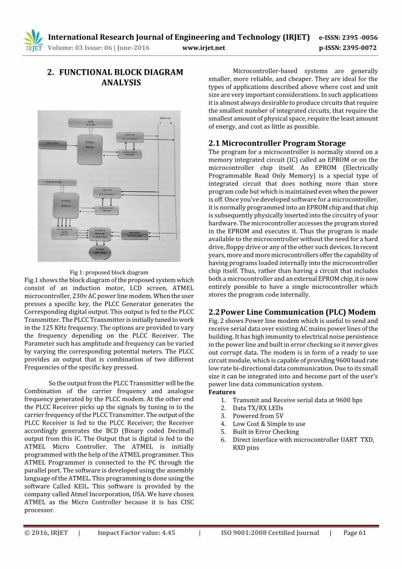
Fig 1: proposed block diagram
Fig.1 shows the block diagram of the proposed system which consist of an induction motor, LCD screen, ATMEL microcontroller, 230v AC power line modem. When the user presses a specific key, the PLCC Generator generates the Corresponding digital output. This output is fed to the PLCC Transmitter. The PLCC Transmitter is initially tuned to work in the 125 KHz frequency. The options are provided to vary the frequency depending on the PLCC Receiver. The Parameter such has amplitude and frequency can be varied by varying the corresponding potential meters. The PLCC provides an output that is combination of two different Frequencies of the specific key pressed. So the output from the PLCC Transmitter will be the Combination of the carrier frequency and analogue frequency generated by the PLCC modem. At the other end the PLCC Receiver picks up the signals by tuning in to the carrier frequency of the PLCC Transmitter. The output of the PLCC Receiver is fed to the PLCC Receiver; the Receiver accordingly generates the BCD (Binary coded Decimal) output from this IC. The Output that is digital is fed to the ATMEL Micro Controller. The ATMEL is initially programmed with the help of the ATMEL programmer. This ATMEL Programmer is connected to the PC through the parallel port. The software is developed using the assembly language of the ATMEL. This programming is done using the software Called KEIL. This software is provided by the company called Atmel Incorporation, USA. We have chosen ATMEL as the Micro Controller because it is has CISC processor.
Microcontroller-based systems are generally smaller, more reliable, and cheaper. They are ideal for the types of applications described above where cost and unit size are very important considerations. In such applications it is almost always desirable to produce circuits that require the smallest number of integrated circuits, that require the smallest amount of physical space, require the least amount of energy, and cost as little as possible.
2.1 Microcontroller Program Storage The program for a microcontroller is normally stored on a memory integrated circuit (IC) called an EPROM or on the microcontroller chip itself. An EPROM (Electrically Programmable Read Only Memory) is a special type of integrated circuit that does nothing more than store program code but which is maintained even when the power is off. Once you’ve developed software for a microcontroller, it is normally programmed into an EPROM chip and that chip is subsequently physically inserted into the circuitry of your hardware. The microcontroller accesses the program stored in the EPROM and executes it. Thus the program is made available to the microcontroller without the need for a hard drive, floppy drive or any of the other such devices. In recent years, more and more microcontrollers offer the capability of having programs loaded internally into the microcontroller chip itself. Thus, rather than having a circuit that includes both a microcontroller and an external EPROM chip, it is now entirely possible to have a single microcontroller which stores the program code internally.
2.2 Power Line Communication (PLC) Modem Fig. 2 shows Power line modem which is useful to send and receive serial data over existing AC mains power lines of the building. It has high immunity to electrical noise persistence in the power line and built in error checking so it never gives out corrupt data. The modem is in form of a ready to use circuit module, which is capable of providing 9600 baud rate low rate bi-directional data communication. Due to its small size it can be integrated into and become part of the user’s power line data communication system. Features
1. Transmit and Receive serial data at 9600 bps 2. Data TX/RX LEDs 3. Powered from 5V 4. Low Cost & Simple to use 5. Built in Error Checking 6. Direct interface with microcontroller UART TXD,
RXD pins
International Research Journal of Engineering and Technology (IRJET) e-ISSN: 2395 -0056
Volume: 03 Issue: 06 | June-2016 www.irjet.net p-ISSN: 2395-0072
© 2016, IRJET | Impact Factor value: 4.45 | ISO 9001:2008 Certified Journal | Page 62
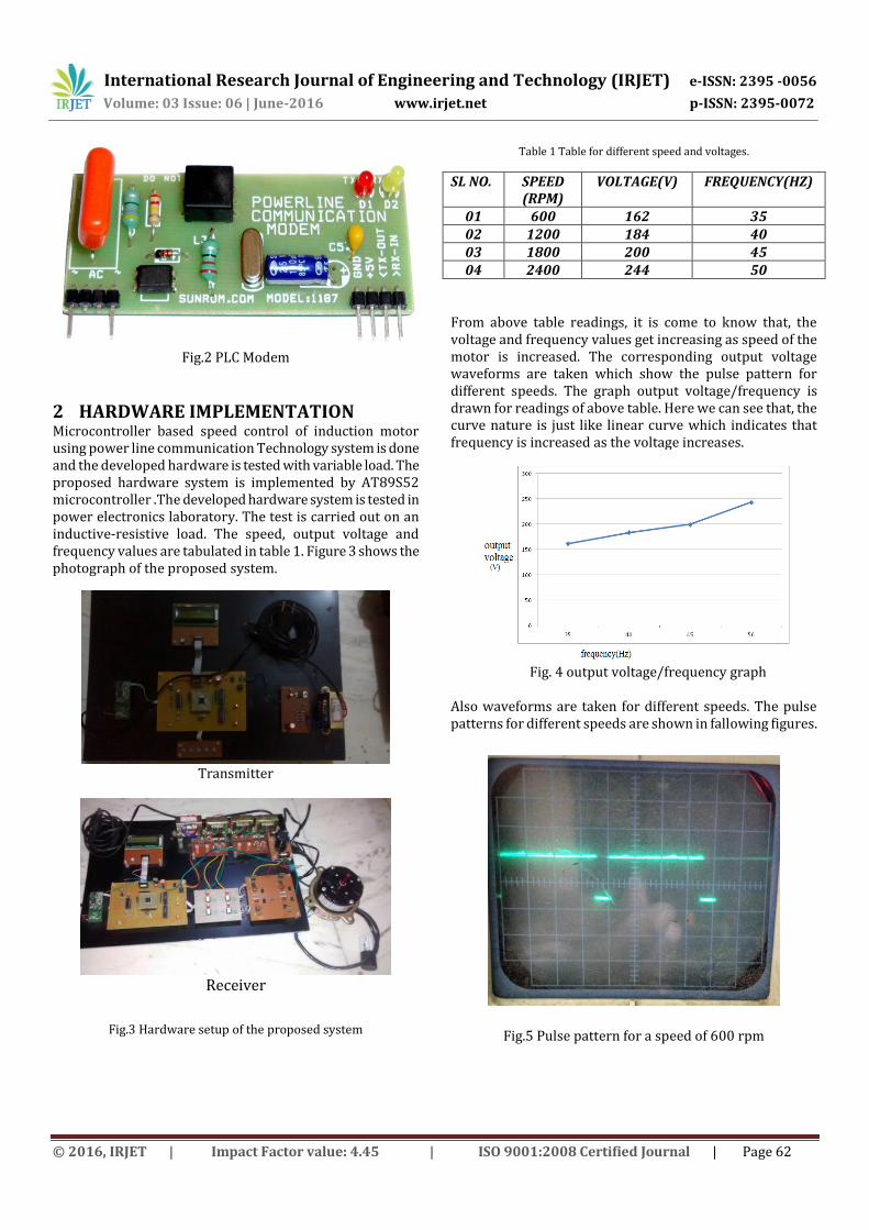
Fig.2 PLC Modem
2 HARDWARE IMPLEMENTATION Microcontroller based speed control of induction motor using power line communication Technology system is done and the developed hardware is tested with variable load. The proposed hardware system is implemented by AT89S52 microcontroller .The developed hardware system is tested in power electronics laboratory. The test is carried out on an inductive-resistive load. The speed, output voltage and frequency values are tabulated in table 1. Figure 3 shows the photograph of the proposed system.
Transmitter
Receiver
Fig.3 Hardware setup of the proposed system
Table 1 Table for different speed and voltages.
SL NO. SPEED (RPM)
VOLTAGE(V) FREQUENCY(HZ)
01 600 162 35 02 1200 184 40 03 1800 200 45 04 2400 244 50
From above table readings, it is come to know that, the voltage and frequency values get increasing as speed of the motor is increased. The corresponding output voltage waveforms are taken which show the pulse pattern for different speeds. The graph output voltage/frequency is drawn for readings of above table. Here we can see that, the curve nature is just like linear curve which indicates that frequency is increased as the voltage increases.
Fig. 4 output voltage/frequency graph
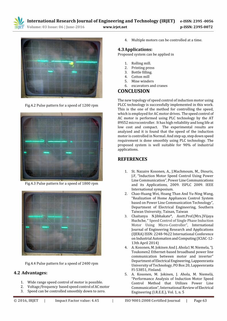
Also waveforms are taken for different speeds. The pulse patterns for different speeds are shown in fallowing figures.
Fig.5 Pulse pattern for a speed of 600 rpm
International Research Journal of Engineering and Technology (IRJET) e-ISSN: 2395 -0056
Volume: 03 Issue: 06 | June-2016 www.irjet.net p-ISSN: 2395-0072
© 2016, IRJET | Impact Factor value: 4.45 | ISO 9001:2008 Certified Journal | Page 63
Fig.4.2 Pulse pattern for a speed of 1200 rpm
Fig.4.3 Pulse pattern for a speed of 1800 rpm
Fig.4.4 Pulse pattern for a speed of 2400 rpm
4.2 Advantages:
1. Wide range speed control of motor is possible. 2. Voltage/frequency based speed control of AC motor 3. Speed can be controlled smoothly down to zero.
4. Multiple motors can be controlled at a time.
4.3 Applications: Proposed system can be applied in
1. Rolling mill. 2. Printing press 3. Bottle filling. 4. Cotton mill 5. Mine winders 6. excavators and cranes
CONCLUSION
The new topology of speed control of induction motor using PLCC technology is successfully implemented in this work. This is the one of the method for controlling the speed, which is employed for AC motor drives. The speed control of AC motor is performed using PLC technology by the AT 89S52 microcontroller. It has high reliability and long life at low cost and compact. The experimental results are analyzed and it is found that the speed of the induction motor is controlled in Normal. And step up, step down speed requirement is done smoothly using PLC technology. The proposed system is well suitable for 90% of industrial applications.
REFERENCES
1. St. Nazaire Kosonen, A., J.Machmoum, M., Diouris,
J.F, “Induction Motor Speed Control Using Power Line Communication”, Power Line Communications and its Applications, 2009. ISPLC 2009. IEEE International symposium.
2. Chao-Huang Wei, Hoang Than And Yu-Ning Wang, “Realization of Home Appliances Control System based on Power Line Communication Technology”, Department of Electrical Engineering, Southern Taiwan University, Tainan, Taiwan
3. Chaitanya N.Jibhakate*, Asstt.Prof.(Mrs.)Vijaya Huchche, “ Speed Control of Single Phase Induction Motor Using Micro-Controller”, International Journal of Engineering Research and Applications (IJERA) ISSN: 2248-9622 International Conference on Industrial Automation and Computing (ICIAC-12-13th April 2014)
4. A. Kosonen, M. Jokinen And J. Ahola1 M. Niemela, “J. Toukonen2 Ethernet-based broadband power line communication between motor and inverter” Department of Electrical Engineering, Lappeenranta University of Technology, PO Box 20, Lappeenranta FI-53851, Finland.
5. A. Kosonen, M. Jokinen, J. Ahola, M. Niemelä, “Performance Analysis of Induction Motor Speed Control Method that Utilizes Power Line Communication”, International Review of Electrical Engineering (I.R.E.E.), Vol. 1, n. 5

International Research Journal of Engineering and Technology (IRJET) e-ISSN: 2395 -0056
Volume: 03 Issue: 06 | June-2016 www.irjet.net p-ISSN: 2395-0072
© 2016, IRJET | Impact Factor value: 4.45 | ISO 9001:2008 Certified Journal | Page 64
6. Niall G, Coakley and Richard C. Kavanagh, “Real-Time Control of a Servosystem Using the Inverter-Fed Power Lines to Communicate Sensor Feedback”, IEEE Transactions on Industrial Electronics, Vol.46, No.2, April 1999.
7. Manfred Zimmermann and Klaus Dostert, “A Multipath Model for the Powerline Chanel”, IEEE Transactions on Communications, Vol.50, No.4, April 2002.
8. Muhammad H. Rashid, “Power Electronics Circuits, Devices and Application” PHI, New Delhi, 2001.
9. B.K., Bose, “Adjustable Speed AC Drives – A Technology status review”, IEEE Transaction, Vol.70, No.2, PP-116-33, Feb-1982.
Author’s Profile:
Apoorva s Biradar, PG Scholar, Dept of EEE, Poojya Doddappa Appa College of Engineering, Gulbarga, Karnataka, India, E-mail: [email protected]
Nagabhushan patil, Professor, Dept. of EEE, Poojya Doddappa Appa College of Engineering, Gulbarga, Karnataka, India, E-mail: [email protected]