Embed Size (px)
Citation preview
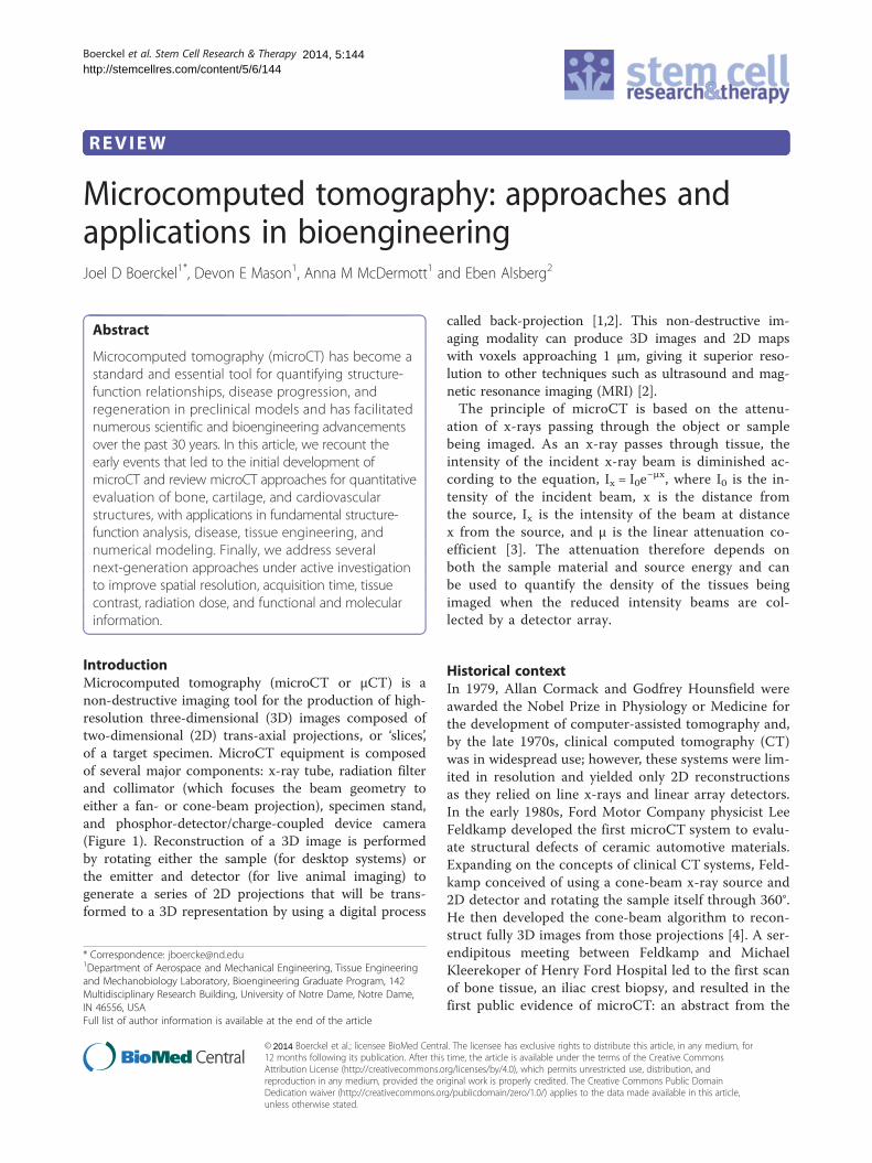
Boerckel et al. Stem Cell Research & Therapy 2014, 5:144http://stemcellres.com/content/5/6/144
REVIEW
Microcomputed tomography: approaches andapplications in bioengineeringJoel D Boerckel1*, Devon E Mason1, Anna M McDermott1 and Eben Alsberg2
Abstract
Microcomputed tomography (microCT) has become astandard and essential tool for quantifying structure-function relationships, disease progression, andregeneration in preclinical models and has facilitatednumerous scientific and bioengineering advancementsover the past 30 years. In this article, we recount theearly events that led to the initial development ofmicroCT and review microCT approaches for quantitativeevaluation of bone, cartilage, and cardiovascularstructures, with applications in fundamental structure-function analysis, disease, tissue engineering, andnumerical modeling. Finally, we address severalnext-generation approaches under active investigationto improve spatial resolution, acquisition time, tissuecontrast, radiation dose, and functional and molecularinformation.
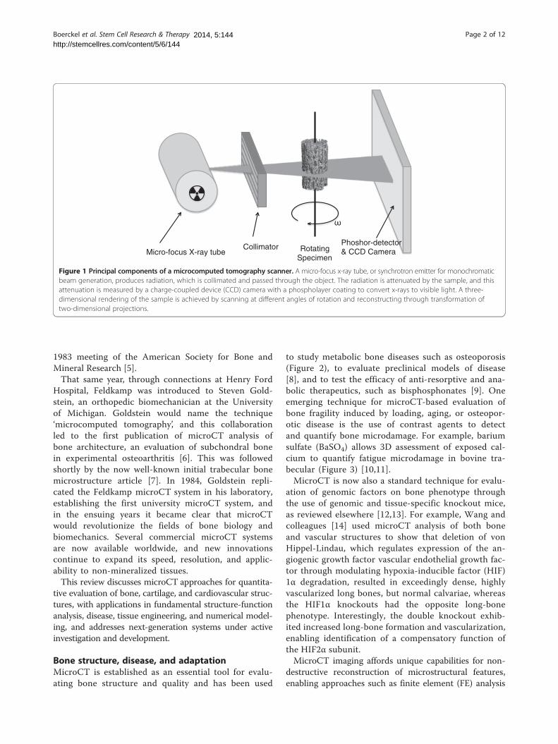
IntroductionMicrocomputed tomography (microCT or μCT) is anon-destructive imaging tool for the production of high-resolution three-dimensional (3D) images composed oftwo-dimensional (2D) trans-axial projections, or ‘slices’,of a target specimen. MicroCT equipment is composedof several major components: x-ray tube, radiation filterand collimator (which focuses the beam geometry toeither a fan- or cone-beam projection), specimen stand,and phosphor-detector/charge-coupled device camera(Figure 1). Reconstruction of a 3D image is performedby rotating either the sample (for desktop systems) orthe emitter and detector (for live animal imaging) togenerate a series of 2D projections that will be trans-formed to a 3D representation by using a digital process
* Correspondence: [email protected] of Aerospace and Mechanical Engineering, Tissue Engineeringand Mechanobiology Laboratory, Bioengineering Graduate Program, 142Multidisciplinary Research Building, University of Notre Dame, Notre Dame,IN 46556, USAFull list of author information is available at the end of the article
© Boerckel et al.; licensee BioMed Centra12 months following its publication. After thisAttribution License (http://creativecommons.oreproduction in any medium, provided the orDedication waiver (http://creativecommons.orunless otherwise stated.
2014
called back-projection [1,2]. This non-destructive im-aging modality can produce 3D images and 2D mapswith voxels approaching 1 μm, giving it superior reso-lution to other techniques such as ultrasound and mag-netic resonance imaging (MRI) [2].The principle of microCT is based on the attenu-
ation of x-rays passing through the object or samplebeing imaged. As an x-ray passes through tissue, theintensity of the incident x-ray beam is diminished ac-cording to the equation, Ix = I0e
−μx, where I0 is the in-tensity of the incident beam, x is the distance fromthe source, Ix is the intensity of the beam at distancex from the source, and μ is the linear attenuation co-efficient [3]. The attenuation therefore depends onboth the sample material and source energy and canbe used to quantify the density of the tissues beingimaged when the reduced intensity beams are col-lected by a detector array.
Historical contextIn 1979, Allan Cormack and Godfrey Hounsfield wereawarded the Nobel Prize in Physiology or Medicine forthe development of computer-assisted tomography and,by the late 1970s, clinical computed tomography (CT)was in widespread use; however, these systems were lim-ited in resolution and yielded only 2D reconstructionsas they relied on line x-rays and linear array detectors.In the early 1980s, Ford Motor Company physicist LeeFeldkamp developed the first microCT system to evalu-ate structural defects of ceramic automotive materials.Expanding on the concepts of clinical CT systems, Feld-kamp conceived of using a cone-beam x-ray source and2D detector and rotating the sample itself through 360°.He then developed the cone-beam algorithm to recon-struct fully 3D images from those projections [4]. A ser-endipitous meeting between Feldkamp and MichaelKleerekoper of Henry Ford Hospital led to the first scanof bone tissue, an iliac crest biopsy, and resulted in thefirst public evidence of microCT: an abstract from the
l. The licensee has exclusive rights to distribute this article, in any medium, fortime, the article is available under the terms of the Creative Commonsrg/licenses/by/4.0), which permits unrestricted use, distribution, andiginal work is properly credited. The Creative Commons Public Domaing/publicdomain/zero/1.0/) applies to the data made available in this article,
Phoshor-detector & CCD Camera Rotating
Specimen Collimator
Micro-focus X-ray tube
Figure 1 Principal components of a microcomputed tomography scanner. A micro-focus x-ray tube, or synchrotron emitter for monochromaticbeam generation, produces radiation, which is collimated and passed through the object. The radiation is attenuated by the sample, and thisattenuation is measured by a charge-coupled device (CCD) camera with a phospholayer coating to convert x-rays to visible light. A three-dimensional rendering of the sample is achieved by scanning at different angles of rotation and reconstructing through transformation oftwo-dimensional projections.
Boerckel et al. Stem Cell Research & Therapy Page 2 of 122014, 5:144http://stemcellres.com/content/5/6/144
1983 meeting of the American Society for Bone andMineral Research [5].That same year, through connections at Henry Ford
Hospital, Feldkamp was introduced to Steven Gold-stein, an orthopedic biomechanician at the Universityof Michigan. Goldstein would name the technique‘microcomputed tomography’, and this collaborationled to the first publication of microCT analysis ofbone architecture, an evaluation of subchondral bonein experimental osteoarthritis [6]. This was followedshortly by the now well-known initial trabecular bonemicrostructure article [7]. In 1984, Goldstein repli-cated the Feldkamp microCT system in his laboratory,establishing the first university microCT system, andin the ensuing years it became clear that microCTwould revolutionize the fields of bone biology andbiomechanics. Several commercial microCT systemsare now available worldwide, and new innovationscontinue to expand its speed, resolution, and applic-ability to non-mineralized tissues.This review discusses microCT approaches for quantita-
tive evaluation of bone, cartilage, and cardiovascular struc-tures, with applications in fundamental structure-functionanalysis, disease, tissue engineering, and numerical model-ing, and addresses next-generation systems under activeinvestigation and development.
Bone structure, disease, and adaptationMicroCT is established as an essential tool for evalu-ating bone structure and quality and has been used
to study metabolic bone diseases such as osteoporosis(Figure 2), to evaluate preclinical models of disease[8], and to test the efficacy of anti-resorptive and ana-bolic therapeutics, such as bisphosphonates [9]. Oneemerging technique for microCT-based evaluation ofbone fragility induced by loading, aging, or osteopor-otic disease is the use of contrast agents to detectand quantify bone microdamage. For example, bariumsulfate (BaSO4) allows 3D assessment of exposed cal-cium to quantify fatigue microdamage in bovine tra-becular (Figure 3) [10,11].MicroCT is now also a standard technique for evalu-
ation of genomic factors on bone phenotype throughthe use of genomic and tissue-specific knockout mice,as reviewed elsewhere [12,13]. For example, Wang andcolleagues [14] used microCT analysis of both boneand vascular structures to show that deletion of vonHippel-Lindau, which regulates expression of the an-giogenic growth factor vascular endothelial growth fac-tor through modulating hypoxia-inducible factor (HIF)1α degradation, resulted in exceedingly dense, highlyvascularized long bones, but normal calvariae, whereasthe HIF1α knockouts had the opposite long-bonephenotype. Interestingly, the double knockout exhib-ited increased long-bone formation and vascularization,enabling identification of a compensatory function ofthe HIF2α subunit.MicroCT imaging affords unique capabilities for non-
destructive reconstruction of microstructural features,enabling approaches such as finite element (FE) analysis
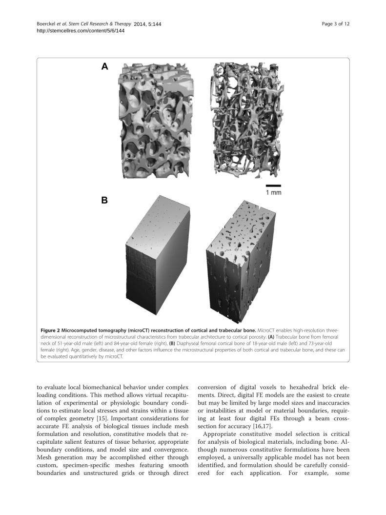
Figure 2 Microcomputed tomography (microCT) reconstruction of cortical and trabecular bone. MicroCT enables high-resolution three-dimensional reconstruction of microstructural characteristics from trabecular architecture to cortical porosity. (A) Trabecular bone from femoralneck of 51-year-old male (left) and 84-year-old female (right). (B) Diaphyseal femoral cortical bone of 18-year-old male (left) and 73-year-oldfemale (right). Age, gender, disease, and other factors influence the microstructural properties of both cortical and trabecular bone, and these canbe evaluated quantitatively by microCT.
Boerckel et al. Stem Cell Research & Therapy Page 3 of 122014, 5:144http://stemcellres.com/content/5/6/144
to evaluate local biomechanical behavior under complexloading conditions. This method allows virtual recapitu-lation of experimental or physiologic boundary condi-tions to estimate local stresses and strains within a tissueof complex geometry [15]. Important considerations foraccurate FE analysis of biological tissues include meshformulation and resolution, constitutive models that re-capitulate salient features of tissue behavior, appropriateboundary conditions, and model size and convergence.Mesh generation may be accomplished either throughcustom, specimen-specific meshes featuring smoothboundaries and unstructured grids or through direct
conversion of digital voxels to hexahedral brick ele-ments. Direct, digital FE models are the easiest to createbut may be limited by large model sizes and inaccuraciesor instabilities at model or material boundaries, requir-ing at least four digital FEs through a beam cross-section for accuracy [16,17].Appropriate constitutive model selection is critical
for analysis of biological materials, including bone. Al-though numerous constitutive formulations have beenemployed, a universally applicable model has not beenidentified, and formulation should be carefully consid-ered for each application. For example, some
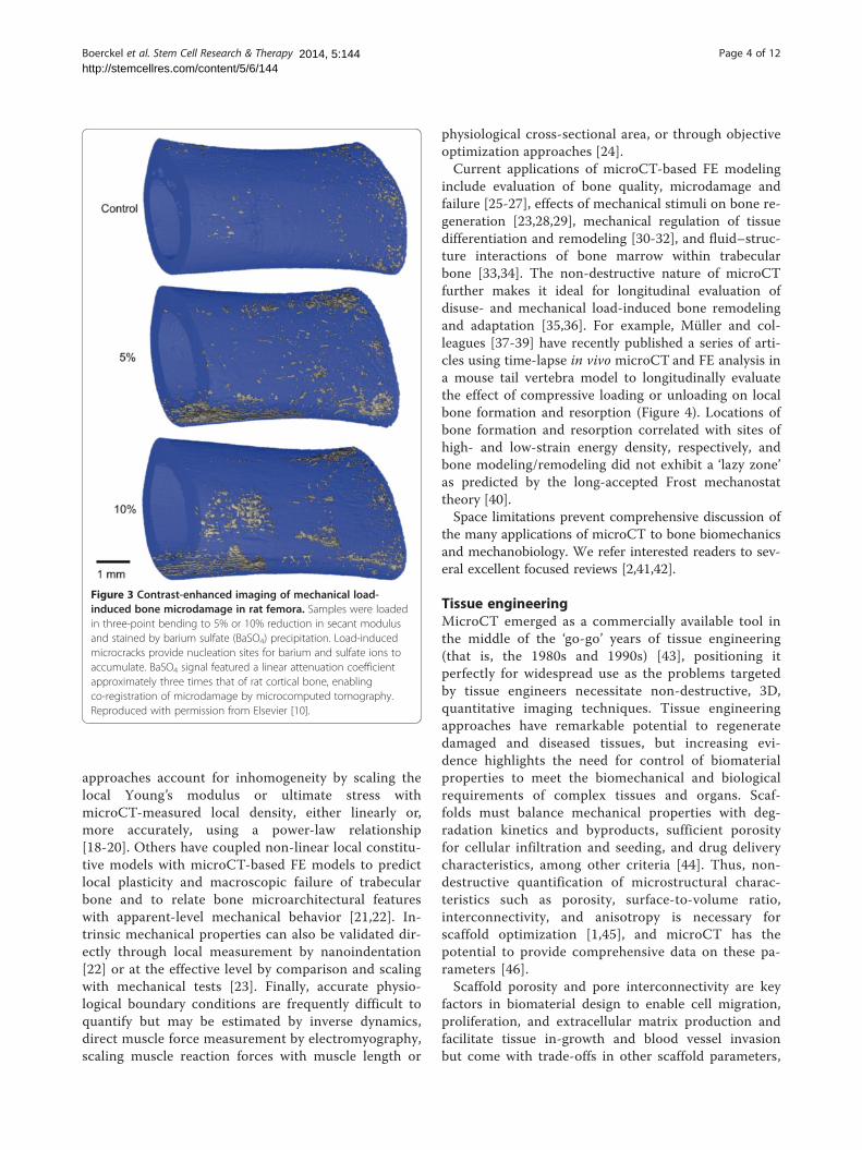
Figure 3 Contrast-enhanced imaging of mechanical load-induced bone microdamage in rat femora. Samples were loadedin three-point bending to 5% or 10% reduction in secant modulusand stained by barium sulfate (BaSO4) precipitation. Load-inducedmicrocracks provide nucleation sites for barium and sulfate ions toaccumulate. BaSO4 signal featured a linear attenuation coefficientapproximately three times that of rat cortical bone, enablingco-registration of microdamage by microcomputed tomography.Reproduced with permission from Elsevier [10].
Boerckel et al. Stem Cell Research & Therapy Page 4 of 122014, 5:144http://stemcellres.com/content/5/6/144
approaches account for inhomogeneity by scaling thelocal Young’s modulus or ultimate stress withmicroCT-measured local density, either linearly or,more accurately, using a power-law relationship[18-20]. Others have coupled non-linear local constitu-tive models with microCT-based FE models to predictlocal plasticity and macroscopic failure of trabecularbone and to relate bone microarchitectural featureswith apparent-level mechanical behavior [21,22]. In-trinsic mechanical properties can also be validated dir-ectly through local measurement by nanoindentation[22] or at the effective level by comparison and scalingwith mechanical tests [23]. Finally, accurate physio-logical boundary conditions are frequently difficult toquantify but may be estimated by inverse dynamics,direct muscle force measurement by electromyography,scaling muscle reaction forces with muscle length or
physiological cross-sectional area, or through objectiveoptimization approaches [24].Current applications of microCT-based FE modeling
include evaluation of bone quality, microdamage andfailure [25-27], effects of mechanical stimuli on bone re-generation [23,28,29], mechanical regulation of tissuedifferentiation and remodeling [30-32], and fluid–struc-ture interactions of bone marrow within trabecularbone [33,34]. The non-destructive nature of microCTfurther makes it ideal for longitudinal evaluation ofdisuse- and mechanical load-induced bone remodelingand adaptation [35,36]. For example, Müller and col-leagues [37-39] have recently published a series of arti-cles using time-lapse in vivo microCT and FE analysis ina mouse tail vertebra model to longitudinally evaluatethe effect of compressive loading or unloading on localbone formation and resorption (Figure 4). Locations ofbone formation and resorption correlated with sites ofhigh- and low-strain energy density, respectively, andbone modeling/remodeling did not exhibit a ‘lazy zone’as predicted by the long-accepted Frost mechanostattheory [40].Space limitations prevent comprehensive discussion of
the many applications of microCT to bone biomechanicsand mechanobiology. We refer interested readers to sev-eral excellent focused reviews [2,41,42].
Tissue engineeringMicroCT emerged as a commercially available tool inthe middle of the ‘go-go’ years of tissue engineering(that is, the 1980s and 1990s) [43], positioning itperfectly for widespread use as the problems targetedby tissue engineers necessitate non-destructive, 3D,quantitative imaging techniques. Tissue engineeringapproaches have remarkable potential to regeneratedamaged and diseased tissues, but increasing evi-dence highlights the need for control of biomaterialproperties to meet the biomechanical and biologicalrequirements of complex tissues and organs. Scaf-folds must balance mechanical properties with deg-radation kinetics and byproducts, sufficient porosityfor cellular infiltration and seeding, and drug deliverycharacteristics, among other criteria [44]. Thus, non-destructive quantification of microstructural charac-teristics such as porosity, surface-to-volume ratio,interconnectivity, and anisotropy is necessary forscaffold optimization [1,45], and microCT has thepotential to provide comprehensive data on these pa-rameters [46].Scaffold porosity and pore interconnectivity are key
factors in biomaterial design to enable cell migration,proliferation, and extracellular matrix production andfacilitate tissue in-growth and blood vessel invasionbut come with trade-offs in other scaffold parameters,
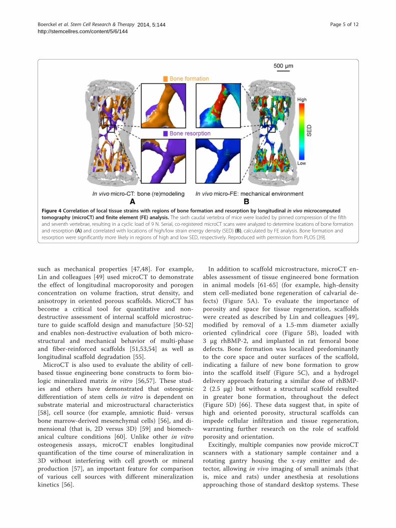
Figure 4 Correlation of local tissue strains with regions of bone formation and resorption by longitudinal in vivo microcomputedtomography (microCT) and finite element (FE) analysis. The sixth caudal vertebra of mice were loaded by pinned compression of the fifthand seventh vertebrae, resulting in a cyclic load of 9 N. Serial, co-registered microCT scans were analyzed to determine locations of bone formationand resorption (A) and correlated with locations of high/low strain energy density (SED) (B), calculated by FE analysis. Bone formation andresorption were significantly more likely in regions of high and low SED, respectively. Reproduced with permission from PLOS [39].
Boerckel et al. Stem Cell Research & Therapy Page 5 of 122014, 5:144http://stemcellres.com/content/5/6/144
such as mechanical properties [47,48]. For example,Lin and colleagues [49] used microCT to demonstratethe effect of longitudinal macroporosity and porogenconcentration on volume fraction, strut density, andanisotropy in oriented porous scaffolds. MicroCT hasbecome a critical tool for quantitative and non-destructive assessment of internal scaffold microstruc-ture to guide scaffold design and manufacture [50-52]and enables non-destructive evaluation of both micro-structural and mechanical behavior of multi-phaseand fiber-reinforced scaffolds [51,53,54] as well aslongitudinal scaffold degradation [55].MicroCT is also used to evaluate the ability of cell-
based tissue engineering bone constructs to form bio-logic mineralized matrix in vitro [56,57]. These stud-ies and others have demonstrated that osteogenicdifferentiation of stem cells in vitro is dependent onsubstrate material and microstructural characteristics[58], cell source (for example, amniotic fluid- versusbone marrow-derived mesenchymal cells) [56], and di-mensional (that is, 2D versus 3D) [59] and biomech-anical culture conditions [60]. Unlike other in vitroosteogenesis assays, microCT enables longitudinalquantification of the time course of mineralization in3D without interfering with cell growth or mineralproduction [57], an important feature for comparisonof various cell sources with different mineralizationkinetics [56].
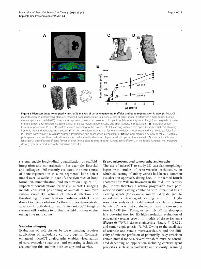
In addition to scaffold microstructure, microCT en-ables assessment of tissue engineered bone formationin animal models [61-65] (for example, high-densitystem cell-mediated bone regeneration of calvarial de-fects) (Figure 5A). To evaluate the importance ofporosity and space for tissue regeneration, scaffoldswere created as described by Lin and colleagues [49],modified by removal of a 1.5-mm diameter axiallyoriented cylindrical core (Figure 5B), loaded with3 μg rhBMP-2, and implanted in rat femoral bonedefects. Bone formation was localized predominantlyto the core space and outer surfaces of the scaffold,indicating a failure of new bone formation to growinto the scaffold itself (Figure 5C), and a hydrogeldelivery approach featuring a similar dose of rhBMP-2 (2.5 μg) but without a structural scaffold resultedin greater bone formation, throughout the defect(Figure 5D) [66]. These data suggest that, in spite ofhigh and oriented porosity, structural scaffolds canimpede cellular infiltration and tissue regeneration,warranting further research on the role of scaffoldporosity and orientation.Excitingly, multiple companies now provide microCT
scanners with a stationary sample container and arotating gantry housing the x-ray emitter and de-tector, allowing in vivo imaging of small animals (thatis, mice and rats) under anesthesia at resolutionsapproaching those of standard desktop systems. These
B
A C D
E
Figure 5 Microcomputed tomography (microCT) analysis of tissue engineering scaffolds and bone regeneration in vivo. (A) MicroCTreconstruction of mesenchymal stem cell-mediated bone regeneration in a bilateral cranial defect model treated with a high-density humanmesenchymal stem cell (hMSC) construct incorporating growth factor-loaded microparticles (left) or empty control (right), and sagittal-cut viewsof three-dimensional thickness mapping overlay of defect regions (Phuong Dang and Eben Aslberg, in preparation). (B) Poly(L/DL)-lactidetri-calcium phosphate (PLDL-TCP) scaffold created according to the protocol of [38] featuring oriented microporosity and central core showingisometric view and transverse cross-section. (C) In vivo bone formation in a rat femoral bone defect model implanted with cored scaffolds from(A) loaded with rhBMP-2 in alginate hydrogel (McDermott and collegues, in preparation) or (D) hydrogel-mediated delivery of rhBMP-2 within apolycaprolactone nanofiber mesh without a structural scaffold in the defect. Reproduced with permission from [49]. (E) In vivo microCT-basedlongitudinal quantification of bone formation over time (dotted to solid lines) for various doses of BMP-2 in the hybrid nanofiber mesh/alginatedelivery system. Reproduced with permission from [49].
Boerckel et al. Stem Cell Research & Therapy Page 6 of 122014, 5:144http://stemcellres.com/content/5/6/144
systems enable longitudinal quantification of scaffold-integration and mineralization. For example, Boerckeland colleagues [66] recently evaluated the time courseof bone regeneration in a rat segmental bone defectmodel over 12 weeks to quantify the dynamics of boneformation, mineralization, and maturation (Figure 5E).Important considerations for in vivo microCT imaginginclude consistent positioning of animals to minimizesystem variability, volume of interest selection andthresholding to avoid fixation hardware artifacts, anddose of ionizing radiation. As these studies demonstrate,advances in both desktop and in vivo microCT imagingsystems will continue to further the field of tissue engin-eering in years to come.
Vascular imagingEvaluation of soft tissues by x-ray imaging requiresapplication of radiodense contrast agents. Contrast-enhanced microCT angiography enables visualizationof cardiovascular structures, and emerging techniquesare enabling this analysis both ex vivo and in vivo.
Ex vivo microcomputed tomography angiographyThe use of microCT to study 3D vascular morphologybegan with studies of reno-vascular architecture, inwhich 3D casting of kidney vessels had been a commonvisualization approach, dating back to the famed Britishanatomist Sir William Bowman in the mid-19th century[67]. It was therefore a natural progression from poly-meric vascular casting combined with interstitial tissueclearing agents (for example, methyl salicylate) [68] toradiodense contrast-agent casting and CT. High-resolution analysis of model animal vascular structuresby microCT was first conducted on renal microvascula-ture in 1998 [69]. Today, ex vivo microCT angiographyis a powerful tool for 3D high-resolution evaluation ofpost-natal vascular growth in models of tissue ischemia(Figure 6) [70,71], tissue engineering (Figure 7) [28,72],and tumor angiogenesis [73,74]. Owing to the small sizeof arteriole and venule microvasculature and the diffi-culty of efficient perfusion of potentially leaky vessels incertain animal models, several variables must be consid-ered depending on application, including contrast-agentproperties such as radiodensity and viscosity, scanning
WT KO
A
B
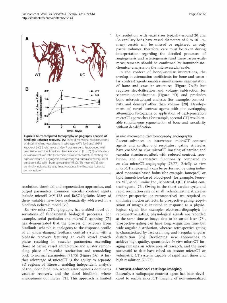
Figure 6 Microcomputed tomography angiography analysis ofhindlimb ischemia recovery. (A) Three-dimensional reconstructionsof distal hindlimb vasculature in wild-type (WT) (left) and MKP-1knockout (KO) (right) mice at day 7 post-surgery. Reproduced withpermission from the American Heart Association [71]. (B) Quantificationof vascular volume ratio (ischemic/contralateral control), illustrating thebiphasic nature of angiogenic and arteriogenic vascular recovery. Initialconditions (T0) taken from comparable WT C57Bl6 mice in [75], withcontinuity indicated by gray lines. Horizontal line illustrates ischemic/control ratio of 1.
Boerckel et al. Stem Cell Research & Therapy Page 7 of 122014, 5:144http://stemcellres.com/content/5/6/144
resolution, threshold and segmentation approaches, andoutput parameters. Common vascular contrast agentsinclude microfil MV-122 and BaSO4/gelatin. Many ofthese variables have been systematically addressed in ahindlimb ischemia model [70].Ex vivo microCT angiography has enabled novel ob-
servations of fundamental biological processes. Forexample, serial perfusion and microCT scanning [75]has demonstrated that the process of recovery fromhindlimb ischemia is analogous to the response profileof an under-damped feedback control system, with abiphasic recovery featuring an early vessel growthphase resulting in vascular parameters exceedingthose of native vessel architecture and a later remod-eling phase of vascular rarefaction and remodelingback to normal parameters [71,75] (Figure 6A). A fur-ther advantage of microCT is the ability to separate3D regions of interest, enabling independent analysisof the upper hindlimb, where arteriogenesis dominatesvascular recovery, and the distal hindlimb, whereangiogenesis dominates [71]. This approach is limited
by resolution, with voxel sizes typically around 20 μm.As capillary beds have vessel diameters of 5 to 10 μm,many vessels will be missed or registered as onlypartial volumes; therefore, care must be taken duringinterpretation regarding the detailed processes ofangiogenesis and arteriogenesis, and these larger-scalemeasurements should be confirmed by immunohisto-chemical analysis on the microvascular scale.In the context of bone/vascular interactions, the
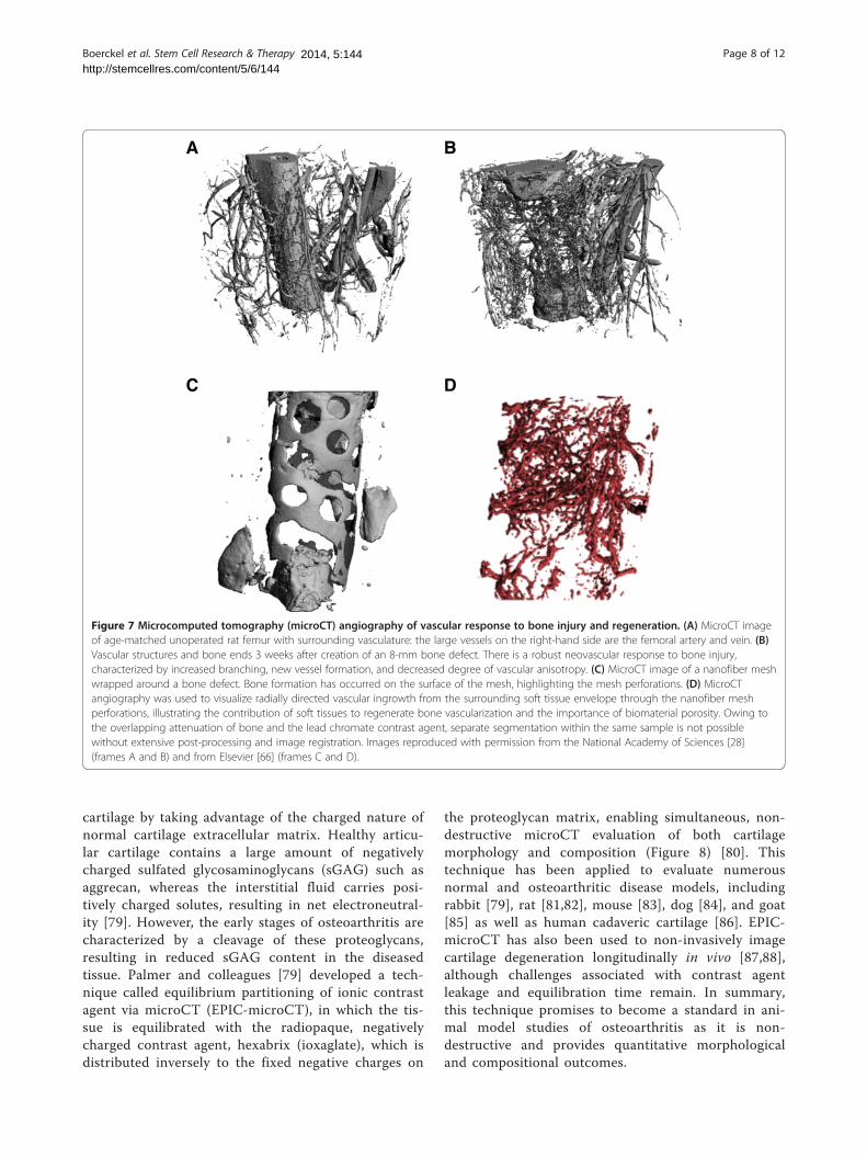
overlap in attenuation coefficients for bone and vascu-lar contrast agents enables simultaneous segmentationof bone and vascular structures (Figure 7A,B) butrequires decalcification and volume subtraction forseparate quantification (Figure 7D) and precludesbone microstructural analyses (for example, connect-ivity and density) other than volume [28]. Develop-ment of novel contrast agents with non-overlappingattenuation histograms or application of next-generationmicroCT approaches (for example, spectral CT) would en-able simultaneous segmentation of bone and vascularitywithout decalcification.
In vivo microcomputed tomography angiographyRecent advances in intravenous microCT contrastagents and cardiac and respiratory gating strategieshave enabled in vivo microCT imaging of cardiac andvascular structures, albeit with reduced contrast, reso-lution, and quantitative functionality compared toex vivo microCT angiography [76,77]. Briefly, in vivomicroCT angiography can be performed by using iodin-ated monomer-based bolus (for example, iomeprol) orlipid immulsion-based blood-pool (for example, Fenes-tra VC, MediLumine Inc., Montreal, QC, Canada) con-trast agents [76]. Owing to the short cardiac cycle andrapid respiration rate of small rodents, gating strategies(either prospective or retrospective) are required tominimize motion artifacts. In prospective gating, acqui-sition of images is initiated in response to a physio-logical signal (for example, electrocardiography); inretrospective gating, physiological signals are recordedat the same time as image data to be sorted later [78].Prospective gating can have long acquisition time butwide-angular distribution, whereas retrospective gatingis characterized by fast scanning and irregular angulardistribution [76]. Developing new approaches toachieve high-quality, quantitative in vivo microCT im-aging remains an active area of research, and the mostsuccessful to date have relied on custom microCT orvolumetric CT systems capable of rapid scan times andhigh resolution [76,77].
Contrast-enhanced cartilage imagingRecently, a radiopaque contrast agent has been devel-oped to enable microCT imaging of non-mineralized
A B
C D
Figure 7 Microcomputed tomography (microCT) angiography of vascular response to bone injury and regeneration. (A) MicroCT imageof age-matched unoperated rat femur with surrounding vasculature: the large vessels on the right-hand side are the femoral artery and vein. (B)Vascular structures and bone ends 3 weeks after creation of an 8-mm bone defect. There is a robust neovascular response to bone injury,characterized by increased branching, new vessel formation, and decreased degree of vascular anisotropy. (C) MicroCT image of a nanofiber meshwrapped around a bone defect. Bone formation has occurred on the surface of the mesh, highlighting the mesh perforations. (D) MicroCTangiography was used to visualize radially directed vascular ingrowth from the surrounding soft tissue envelope through the nanofiber meshperforations, illustrating the contribution of soft tissues to regenerate bone vascularization and the importance of biomaterial porosity. Owing tothe overlapping attenuation of bone and the lead chromate contrast agent, separate segmentation within the same sample is not possiblewithout extensive post-processing and image registration. Images reproduced with permission from the National Academy of Sciences [28](frames A and B) and from Elsevier [66] (frames C and D).
Boerckel et al. Stem Cell Research & Therapy Page 8 of 122014, 5:144http://stemcellres.com/content/5/6/144
cartilage by taking advantage of the charged nature ofnormal cartilage extracellular matrix. Healthy articu-lar cartilage contains a large amount of negativelycharged sulfated glycosaminoglycans (sGAG) such asaggrecan, whereas the interstitial fluid carries posi-tively charged solutes, resulting in net electroneutral-ity [79]. However, the early stages of osteoarthritis arecharacterized by a cleavage of these proteoglycans,resulting in reduced sGAG content in the diseasedtissue. Palmer and colleagues [79] developed a tech-nique called equilibrium partitioning of ionic contrastagent via microCT (EPIC-microCT), in which the tis-sue is equilibrated with the radiopaque, negativelycharged contrast agent, hexabrix (ioxaglate), which isdistributed inversely to the fixed negative charges on
the proteoglycan matrix, enabling simultaneous, non-destructive microCT evaluation of both cartilagemorphology and composition (Figure 8) [80]. Thistechnique has been applied to evaluate numerousnormal and osteoarthritic disease models, includingrabbit [79], rat [81,82], mouse [83], dog [84], and goat[85] as well as human cadaveric cartilage [86]. EPIC-microCT has also been used to non-invasively imagecartilage degeneration longitudinally in vivo [87,88],although challenges associated with contrast agentleakage and equilibration time remain. In summary,this technique promises to become a standard in ani-mal model studies of osteoarthritis as it is non-destructive and provides quantitative morphologicaland compositional outcomes.
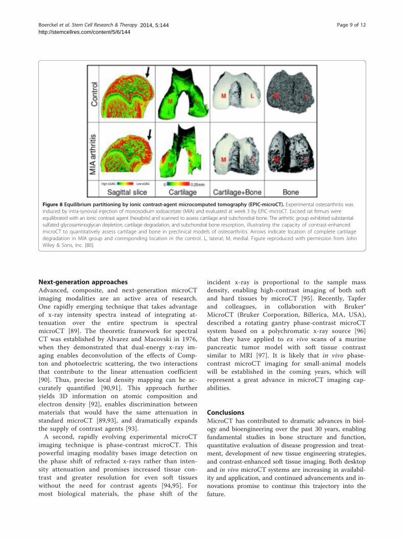
Figure 8 Equilibrium partitioning by ionic contrast-agent microcomputed tomography (EPIC-microCT). Experimental osteoarthritis wasinduced by intra-synovial injection of monosodium iodoacetate (MIA) and evaluated at week 3 by EPIC-microCT. Excised rat femurs wereequilibrated with an ionic contrast agent (hexabrix) and scanned to assess cartilage and subchondral bone. The arthritic group exhibited substantialsulfated glycosaminoglycan depletion, cartilage degradation, and subchondral bone resorption, illustrating the capacity of contrast-enhancedmicroCT to quantitatively assess cartilage and bone in preclinical models of osteoarthritis. Arrows indicate location of complete cartilagedegradation in MIA group and corresponding location in the control. L, lateral; M, medial. Figure reproduced with permission from JohnWiley & Sons, Inc. [80].
Boerckel et al. Stem Cell Research & Therapy Page 9 of 122014, 5:144http://stemcellres.com/content/5/6/144
Next-generation approachesAdvanced, composite, and next-generation microCTimaging modalities are an active area of research.One rapidly emerging technique that takes advantageof x-ray intensity spectra instead of integrating at-tenuation over the entire spectrum is spectralmicroCT [89]. The theoretic framework for spectralCT was established by Alvarez and Macovski in 1976,when they demonstrated that dual-energy x-ray im-aging enables deconvolution of the effects of Comp-ton and photoelectric scattering, the two interactionsthat contribute to the linear attenuation coefficient[90]. Thus, precise local density mapping can be ac-curately quantified [90,91]. This approach furtheryields 3D information on atomic composition andelectron density [92], enables discrimination betweenmaterials that would have the same attenuation instandard microCT [89,93], and dramatically expandsthe supply of contrast agents [93].A second, rapidly evolving experimental microCT
imaging technique is phase-contrast microCT. Thispowerful imaging modality bases image detection onthe phase shift of refracted x-rays rather than inten-sity attenuation and promises increased tissue con-trast and greater resolution for even soft tissueswithout the need for contrast agents [94,95]. Formost biological materials, the phase shift of the
incident x-ray is proportional to the sample massdensity, enabling high-contrast imaging of both softand hard tissues by microCT [95]. Recently, Tapferand colleagues, in collaboration with Bruker®MicroCT (Bruker Corporation, Billerica, MA, USA),described a rotating gantry phase-contrast microCTsystem based on a polychromatic x-ray source [96]that they have applied to ex vivo scans of a murinepancreatic tumor model with soft tissue contrastsimilar to MRI [97]. It is likely that in vivo phase-contrast microCT imaging for small-animal modelswill be established in the coming years, which willrepresent a great advance in microCT imaging cap-abilities.
ConclusionsMicroCT has contributed to dramatic advances in biol-ogy and bioengineering over the past 30 years, enablingfundamental studies in bone structure and function,quantitative evaluation of disease progression and treat-ment, development of new tissue engineering strategies,and contrast-enhanced soft tissue imaging. Both desktopand in vivo microCT systems are increasing in availabil-ity and application, and continued advancements and in-novations promise to continue this trajectory into thefuture.
Note: This article is part of a thematic series on Functionalimaging in regenerative medicine.
Boerckel et al. Stem Cell Research & Therapy Page 10 of 122014, 5:144http://stemcellres.com/content/5/6/144
Abbreviations2D: Two-dimensional; 3D: Three-dimensional; BaSO4: Barium sulfate;CT: Computed tomography; EPIC-microCT: Equilibrium partitioning of ioniccontrast agent via microcomputed tomography; FE: Finite element;HIF: Hypoxia-inducible factor; microCT: Microcomputed tomography;MRI: Magnetic resonance imaging; sGAG: Sulfated glycosaminoglycans.
Competing interestsThe authors declare that they have no competing interests.
AcknowledgmentsThe authors thank Steven Goldstein of the University of Michigan for helpfuldiscussions and descriptions of events surrounding the invention and earlyimplementation of microCT.
Author details1Department of Aerospace and Mechanical Engineering, Tissue Engineeringand Mechanobiology Laboratory, Bioengineering Graduate Program, 142Multidisciplinary Research Building, University of Notre Dame, Notre Dame,IN 46556, USA. 2Department of Biomedical Engineering, Wickenden Bldg,Room 204, 10900 Euclid Ave, Cleveland, OH 44106, USA.
Published:
References1. Guldberg RE, Ballock RT, Boyan BD, Duvall CL, Lin ASP, Nagaraja S, Oest M,
Phillips J, Porter BD, Robertson G, Taylor WR. Analyzing bone, bloodvessels, and biomaterials with microcomputed tomography. IEEE EngMed Biol Mag. 2003; 22:77–83.
2. Müller R. Hierarchical microimaging of bone structure and function. NatRev Rheumatol. 2009; 5:373–81.
3. Stauber M, Müller R. Micro-computed tomography: a method for thenon-destructive evaluation of the three-dimensional structure ofbiological specimens. Methods Mol Biol. 2008; 455:273–92.
4. Feldkamp LA, Davis LC, Kress JW. Practical cone-beam algorithm. J OptSoc Am A. 1984; 1:612–9.
5. Feldkamp LA, Kleerekoper M, Kress JW, Freeling R, Mathews CH, Parfitt AM.Investigation of three-dimensional structure of trabecular bone bycomputed tomography of iliac biopsy samples [abstract]. Calcif Tissue Int.1983; 35:669.
6. Layton MW, Goldstein SA, Goulet RW, Feldkamp LA, Kubinski DJ, Bole GG.Examination of subchondral bone architecture in experimentalosteoarthritis by microscopic computed axial tomography. Arthritis Rheum.1988; 31:1400–5.
7. Feldkamp LA, Goldstein SA, Parfitt AM, Jesion G, Kleerekoper M. The directexamination of three-dimensional bone architecture in vitro bycomputed tomography. J Bone Miner Res. 1989; 4:3–11.
8. Ito M, Nishida A, Nakamura T, Uetani M, Hayashi K. Differences of three-dimensional trabecular microstructure in osteopenic rat models causedby ovariectomy and neurectomy. Bone. 2002; 30:594–8.
9. O’Neal JM, Diab T, Allen MR, Vidakovic B, Burr DB, Guldberg RE. One year ofalendronate treatment lowers microstructural stresses associated withtrabecular microdamage initiation. Bone. 2010; 47:241–7.
10. Turnbull TL, Gargac JA, Niebur GL, Roeder RK. Detection of fatiguemicrodamage in whole rat femora using contrast-enhanced micro-computed tomography. J Biomech. 2011; 44:2395–400.
11. Landrigan MD, Li J, Turnbull TL, Burr DB, Niebur GL, Roeder RK. Contrast-enhanced micro-computed tomography of fatigue microdamageaccumulation in human cortical bone. Bone. 2011; 48:443–50.
12. Gregg CL, Butcher JT. Quantitative in vivo imaging of embryonicdevelopment: opportunities and challenges. Differentiation. 2012; 84:149–62.
13. Guldberg RE, Lin ASP, Coleman R, Robertson G, Duvall C. Microcomputedtomography imaging of skeletal development and growth. Birth DefectsRes C Embryo Today. 2004; 72:250–9.
29 Dec 2014
14. Wang Y, Wan C, Deng L, Liu X, Cao X, Gilbert SR, Bouxsein ML, Faugere M,Guldberg RE, Gerstenfeld LC, Haase VH, Johnson RS, Schipani E, Clemens TL.The hypoxia-inducible factor α pathway couples angiogenesis toosteogenesis during skeletal development. J Clin Invest. 2007; 117:1616–26.
15. Van Rietbergen B, Weinans H, Huiskes R, Odgaard A. A new method todetermine trabecular bone elastic properties and loading usingmicromechanical finite-element models. J Biomech. 1995; 28:69–81.
16. Guldberg RE, Hollister SJ, Charras GT. The accuracy of digital image-basedfinite element models. J Biomech Eng. 1998; 120:289–95.
17. Niebur GL, Yuen JC, Hsia AC, Keaveny TM. Convergence behavior of high-resolution finite element models of trabecular bone. J Biomech Eng. 1999;121:629–35.
18. Morgan EF, Bayraktar HH, Keaveny TM. Trabecular bone modulus-densityrelationships depend on anatomic site. J Biomech. 2003; 36:897–904.
19. Keller TS. Predicting the compressive mechanical behavior of bone. JBiomech. 1994; 27:1159–68.
20. Keyak JH, Rossi SA, Jones KA, Skinner HB. Prediction of femoral fractureload using automated finite element modeling. J Biomech. 1998; 31:125–33.
21. Verhulp E, van Rietbergen B, Müller R, Huiskes R. Indirect determination oftrabecular bone effective tissue failure properties using micro-finiteelement simulations. J Biomech. 2008; 41:1479–85.
22. Harrison NM, McHugh PE. Comparison of trabecular bone behavior incore and whole bone samples using high-resolution modeling of a ver-tebral body. Biomech Model Mechanobiol. 2010; 9:469–80.
23. Boerckel JD, Kolambkar YM, Stevens HY, Lin AS, Dupont KM, Guldberg RE.Effects of in vivo mechanical loading on large bone defect regeneration.J Orthop Res. 2012; 30:1067–75.
24. Erdemir A, McLean S, Herzog W, van den Bogert AJ. Model-based estimationof muscle forces exerted during movements. Clin Biomech. 2007;22:131–54.
25. Nagaraja S, Skrinjar O, Guldberg RE. Spatial correlations of trabecular bonemicrodamage with local stresses and strains using rigid image registration.J Biomech Eng. 2011; 133:064502.
26. Green JO, Diab T, Allen MR, Vidakovic B, Burr DB, Guldberg RE. Three yearsof alendronate treatment does not continue to decrease microstructuralstresses and strains associated with trabecular microdamage initiationbeyond those at 1 year. Osteoporos Int. 2012; 23:2313–20.
27. Gargac JA, Turnbull TL, Roeder RK, Niebur GL. A probabilistic damage modelbased on direct 3-D correlation of strain to damage formation followingfatigue loading of rat femora. J Mech Behav Biomed Mater. 2014; 30:234–43.
28. Boerckel JD, Uhrig BA, Willett NJ, Huebsch N, Guldberg RE. Mechanicalregulation of vascular growth and tissue regeneration in vivo. Proc NatlAcad Sci U S A. 2011; 108:E674–80.
29. Mehta M, Checa S, Lienau J, Hutmacher D, Duda GN. In vivo tracking ofsegmental bone defect healing reveals that callus patterning is relatedto early mechanical stimuli. Eur Cell Mater. 2012; 24:358–71. discussion 371.
30. Byrne DP, Lacroix D, Prendergast PJ. Simulation of fracture healing in thetibia: mechanoregulation of cell activity using a lattice modelingapproach. J Orthop Res. 2011; 29:1496–503.
31. Hayward LN, Morgan EF. Assessment of a mechano-regulation theory ofskeletal tissue differentiation in an in vivo model of mechanically in-duced cartilage formation. Biomech Model Mechanobiol. 2009; 8:447–55.
32. Isaksson H, Gröngröft I, Wilson W, van Donkelaar CC, van Rietbergen B, Tami A,Huiskes R, Ito K. Remodeling of fracture callus in mice is consistent withmechanical loading and bone remodeling theory. J Orthop Res. 2009; 27:664–72.
33. Birmingham E, Kreipke TC, Dolan EB, Coughlin TR, Owens P, McNamara LM,Niebur GL, McHugh PE. Mechanical stimulation of bone marrow in situinduces bone formation in trabecular explants. Ann Biomed Eng. 2014[Epub ahead of print].
34. Coughlin TR, Niebur GL. Fluid shear stress in trabecular bone marrow dueto low-magnitude high-frequency vibration. J Biomech. 2012; 45:2222–9.
35. Robling AG, Hinant FM, Burr DB, Turner CH. Improved bone structure andstrength after long-term mechanical loading is greatest if loading isseparated into short bouts. J Bone Miner Res. 2002; 17:1545–54.
36. Sugiyama T, Meakin LB, Browne WJ, Galea GL, Price JS, Lanyon LE. Bones’adaptive response to mechanical loading is essentially linear between thelow strains associated with disuse and the high strains associated with thelamellar/woven bone transition. J Bone Miner Res. 2012; 27:1784–93.
37. Schulte FA, Lambers FM, Kuhn G, Müller R. In vivo micro-computedtomography allows direct three-dimensional quantification of bothbone formation and bone resorption parameters using time-lapsedimaging. Bone. 2011; 48:433–42.
Boerckel et al. Stem Cell Research & Therapy Page 11 of 122014, 5:144http://stemcellres.com/content/5/6/144
38. Lukas C, Ruffoni D, Lambers FM, Schulte FA, Kuhn G, Kollmannsberger P,Weinkamer R, Müller R. Mineralization kinetics in murine trabecular bonequantified by time-lapsed in vivo micro-computed tomography. Bone.2013; 56:55–60.
39. Schulte FA, Ruffoni D, Lambers FM, Christen D, Webster DJ, Kuhn G, MüllerR. Local mechanical stimuli regulate bone formation and resorption inmice at the tissue level. PLoS One. 2013; 8:e62172.
40. Frost HM. Bone’s mechanostat: a 2003 update. Anat Rec A Discov Mol CellEvol Biol. 2003; 275:1081–101.
41. Bouxsein ML, Boyd SK, Christiansen BA, Guldberg RE, Jepsen KJ, Müller R.Guidelines for assessment of bone microstructure in rodents usingmicro-computed tomography. J Bone Miner Res. 2010; 25:1468–86.
42. Van Rietbergen B. Micro-FE analyses of bone: state of the art. Adv Exp MedBiol. 2001; 496:21–30.
43. Badylak SF, Nerem RM. Progress in tissue engineering and regenerativemedicine. Proc Natl Acad Sci U S A. 2010; 107:3285–6.
44. Lin CY, Kikuchi N, Hollister SJ. A novel method for biomaterial scaffoldinternal architecture design to match bone elastic properties withdesired porosity. J Biomech. 2004; 37:623–36.
45. Murphy WL, Dennis RG, Kileny JL, Mooney DJ. Salt fusion: an approach toimprove pore interconnectivity within tissue engineering scaffolds. TissueEng. 2002; 8:43–52.
46. Ho ST, Hutmacher DW. A comparison of micro CT with other techniquesused in the characterization of scaffolds. Biomaterials. 2006; 27:1362–76.
47. Freed LE, Vunjak-Novakovic G, Biron RJ, Eagles DB, Lesnoy DC, Barlow SK,Langer R. Biodegradable polymer scaffolds for tissue engineering.Biotechnology (N Y). 1994; 12:689–93.
48. Kim J, Li WA, Sands W, Mooney DJ. Effect of pore structure ofmacroporous poly(lactide-co-glycolide) scaffolds on the in vivoenrichment of dendritic cells. ACS Appl Mater Interfaces. 2014; 6:8505–12.
49. Lin ASP, Barrows TH, Cartmell SH, Guldberg RE. Microarchitectural andmechanical characterization of oriented porous polymer scaffolds.Biomaterials. 2003; 24:481–9.
50. Williams JM, Adewunmi A, Schek RM, Flanagan CL, Krebsbach PH, FeinbergSE, Hollister SJ, Das S. Bone tissue engineering using polycaprolactonescaffolds fabricated via selective laser sintering. Biomaterials.2005; 26:4817–27.
51. Lohfeld S, Cahill S, Barron V, McHugh P, Dürselen L, Kreja L, Bausewein C,Ignatius A. Fabrication, mechanical and in vivo performance ofpolycaprolactone/tricalcium phosphate composite scaffolds. ActaBiomater. 2012; 8:3446–56.
52. Saito E, Suarez-Gonzalez D, Rao RR, Stegemann JP, Murphy WL, Hollister SJ.Use of micro-computed tomography to nondestructively characterizebiomineral coatings on solid freeform fabricated poly (L-lactic acid) andpoly ((ε-caprolactone) scaffolds in vitro and in vivo. Tissue Eng Part CMethods. 2013; 19:507–17.
53. Converse GL, Conrad TL, Merrill CH, Roeder RK. Hydroxyapatite whisker-reinforced polyetherketoneketone bone ingrowth scaffolds. ActaBiomater. 2010; 6:856–63.
54. Doyle H, Lohfeld S, McHugh P. Predicting the elastic properties ofselective laser sintered PCL/β-TCP bone scaffold materials usingcomputational modelling. Ann Biomed Eng. 2014; 42:661–77.
55. Behravesh E, Timmer MD, Lemoine JJ, Liebschner MA, Mikos AG. Evaluationof the in vitro degradation of macroporous hydrogels using gravimetry,confined compression testing, and microcomputed tomography.Biomacromolecules. 2002; 3:1263–70.
56. Peister A, Woodruff MA, Prince JJ, Gray DP, Hutmacher DW, Guldberg RE.Cell sourcing for bone tissue engineering: amniotic fluid stem cells havea delayed, robust differentiation compared to mesenchymal stem cells.Stem Cell Res. 2011; 7:17–27.
57. Thimm BW, Wechsler O, Bohner M, Müller R, Hofmann S. In vitroceramic scaffold mineralization: comparison between histologicaland micro-computed tomographical analysis. Ann Biomed Eng. 2013;41:2666–75.
58. Peister A, Deutsch ER, Kolambkar Y, Hutmacher DW, Guldberg RE. Amnioticfluid stem cells produce robust mineral deposits on biodegradablescaffolds. Tissue Eng Part A. 2009; 15:3129–38.
59. Shen FH, Werner BC, Liang H, Shang H, Yang N, Li X, Shimer AL, Balian G,Katz AJ. Implications of adipose-derived stromal cells in a 3D culturesystem for osteogenic differentiation: an in vitro and in vivo investigation.Spine J. 2013; 13:32–43.
60. Zhang ZY, Teoh SH, Teo EY, Khoon Chong MS, Shin CW, Tien FT, Choolani MA,Chan JK. A comparison of bioreactors for culture of fetal mesenchymalstem cells for bone tissue engineering. Biomaterials. 2010; 31:8684–95.
61. Kempen DH, Yaszemski MJ, Heijink A, Hefferan TE, Creemers LB, Britson J, MaranA, Classic KL, Dhert WJ, Lu L. Non-invasive monitoring of BMP-2 retentionand bone formation in composites for bone tissue engineering usingSPECT/CT and scintillation probes. J Control Release. 2009; 134:169–76.
62. Kolambkar YM, Dupont KM, Boerckel JD, Huebsch N, Mooney DJ,Hutmacher DW, Guldberg RE. An alginate-based hybrid system for growthfactor delivery in the functional repair of large bone defects. Biomaterials.2011; 32:65–74.
63. Ratanavaraporn J, Furuya H, Kohara H, Tabata Y. Synergistic effects of thedual release of stromal cell-derived factor-1 and bone morphogeneticprotein-2 from hydrogels on bone regeneration. Biomaterials.2011; 32:2797–811.
64. Van Lenthe GH, Hagenmüller H, Bohner M, Hollister SJ, Meinel L, Müller R.Nondestructive micro-computed tomography for biological imaging andquantification of scaffold-bone interaction in vivo. Biomaterials. 2007;28:2479–90.
65. Saito E, Liao EE, Hu W-W, Krebsbach PH, Hollister SJ. Effects of designedPLLA and 50:50 PLGA scaffold architectures on bone formation in vivo.J Tissue Eng Regen Med. 2013; 7:99–111.
66. Boerckel JD, Kolambkar YM, Dupont KM, Uhrig BA, Phelps EA, StevensHY, García AJ, Guldberg RE. Effects of protein dose and deliverysystem on BMP-mediated bone regeneration. Biomaterials. 2011;32:5241–51.
67. Bowman W. On the structure and use of the malpighian bodies of thekidney, with observations on the circulation through that gland. PhilosTrans R Soc London. 1842; 132:57–80.
68. Beeuwkes R, Bonventre JV. Tubular organization and vascular-tubularrelations in the dog kidney. Am J Physiol. 1975; 229:695–713.
69. Garcia-Sanz A, Rodriguez-Barbero A, Bentley MD, Ritman EL, Romero JC.Three-dimensional microcomputed tomography of renal vasculature inrats. Hypertension. 1998; 31:440–4.
70. Duvall CL, Taylor WR, Weiss D, Guldberg RE. Quantitative microcomputedtomography analysis of collateral vessel development after ischemicinjury. Am J Physiol Heart Circ Physiol. 2004; 287:H302–10.
71. Boerckel JD, Chandrasekharan UM, Waitkus MS, Tillmaand EG, Bartlett R,DiCorleto PE. Mitogen-activated protein kinase phosphatase-1 promotesneovascularization and angiogenic gene expression. Arterioscler ThrombVasc Biol. 2014; 34:1020–31.
72. Phelps EA, Landázuri N, Thulé PM, Taylor WR, García AJ. Bioartificial matricesfor therapeutic vascularization. Proc Natl Acad Sci U S A. 2010; 107:3323–8.
73. Savai R, Langheinrich AC, Schermuly RT, Pullamsetti SS, Dumitrascu R,Traupe H, Rau WS, Seeger W, Grimminger F, Banat GA. Evaluation ofangiogenesis using micro-computed tomography in a xenograft mousemodel of lung cancer. Neoplasia. 2009; 11:48–56.
74. Missbach-Guentner J, Hunia J, Alves F. Tumor blood vessel visualization.Int J Dev Biol. 2011; 55:535–46.
75. Landázuri N, Joseph G, Guldberg RE, Taylor WR. Growth and regression ofvasculature in healthy and diabetic mice after hind limb ischemia.Am J Physiol Regul Integr Comp Physiol. 2012; 303:R48–56.
76. Badea CT, Drangova M, Holdsworth DW, Johnson GA. In vivo small-animalimaging using micro-CT and digital subtraction angiography. Phys MedBiol. 2008; 53:R319–50.
77. Schambach SJ, Bag S, Schilling L, Groden C, Brockmann MA. Application ofmicro-CT in small animal imaging. Methods. 2010; 50:2–13.
78. Badea C, Hedlund LW, Johnson GA. Micro-CT with respiratory and cardiacgating. Med Phys. 2004; 31:3324–9.
79. Palmer AW, Guldberg RE, Levenston ME. Analysis of cartilage matrix fixedcharge density and three-dimensional morphology via contrast-enhanced microcomputed tomography. Proc Natl Acad Sci U S A. 2006;103:19255–60.
80. Xie L, Lin AS, Kundu K, Levenston ME, Murthy N, Guldberg RE. Quantitativeimaging of cartilage and bone morphology, reactive oxygen species,and vascularization in a rodent model of osteoarthritis. Arthritis Rheum.2012; 64:1899–908.
81. Thote T, Lin AS, Raji Y, Moran S, Stevens HY, Hart M, Kamath RV, GuldbergRE, Willett NJ. Localized 3D analysis of cartilage composition andmorphology in small animal models of joint degeneration. OsteoarthritisCartilage. 2013; 21:1132–41.
Boerckel et al. Stem Cell Research & Therapy Page 12 of 122014, 5:144http://stemcellres.com/content/5/6/144
82. Willett NJ, Thote T, Lin AS, Moran S, Raji Y, Sridaran S, Stevens HY, GuldbergRE. Intra-articular injection of micronized dehydrated human amnion/chorion membrane attenuates osteoarthritis development. Arthritis ResTher. 2014; 16:R47.
83. Kotwal N, Li J, Sandy J, Plaas A, Sumner DR. Initial application of EPIC-μCTto assess mouse articular cartilage morphology and composition: effectsof aging and treadmill running. Osteoarthritis Cartilage. 2012; 20:887–95.
84. Lau SF, Wolschrijn CF, Siebelt M, Vernooij JC, Voorhout G, Hazewinkel HA.Assessment of articular cartilage and subchondral bone using EPIC-microCT in Labrador retrievers with incipient medial coronoid disease.Vet J. 2013; 198:116–21.
85. Kok AC, Tuijthof GJ, den Dunnen S, van Tiel J, Siebelt M, Everts V, van DijkCN, Kerkhoffs GM. No effect of hole geometry in microfracture for talarosteochondral defects. Clin Orthop Relat Res. 2013; 471:3653–62.
86. Renders GA, Mulder L, Lin AS, Langenbach GE, Koolstra JH, Guldberg RE,Everts V. Contrast-enhanced microCT (EPIC-μCT) ex vivo applied to themouse and human jaw joint. Dentomaxillofac Radiol. 2014; 43:20130098.
87. Piscaer TM, Waarsing JH, Kops N, Pavljasevic P, Verhaar JA, van Osch GJ,Weinans H. In vivo imaging of cartilage degeneration using microCT-arthrography. Osteoarthritis Cartilage. 2008; 16:1011–7.
88. Siebelt M, Waarsing JH, Kops N, Piscaer TM, Verhaar JA, Oei EH, Weinans H.Quantifying osteoarthritic cartilage changes accurately using in vivomicroCT arthrography in three etiologically distinct rat models. J OrthopRes. 2011; 29:1788–94.
89. He P, Yu H, Bennett J, Ronaldson P, Zainon R, Butler A, Butler P, Wei B,Wang G. Energy-discriminative performance of a spectral micro-CTsystem. J Xray Sci Technol. 2013; 21:335–45.
90. Alvarez RE, Macovski A. Energy-selective reconstructions in X-ray comput-erized tomography. Phys Med Biol. 1976; 21:733–44.
91. Nuzzo S, Peyrin F, Cloetens P, Baruchel J, Boivin G. Quantification of thedegree of mineralization of bone in three dimensions using synchrotronradiation microtomography. Med Phys. 2002; 29:2672–81.
92. Anderson NG, Butler AP. Clinical applications of spectral molecularimaging: potential and challenges. Contrast Media Mol Imaging. 2014;9:3–12.
93. Granton PV, Pollmann SI, Ford NL, Drangova M, Holdsworth DW.Implementation of dual- and triple-energy cone-beam micro-CT for post-reconstruction material decomposition. Med Phys. 2008; 35:5030.
94. Clark DP, Badea CT. Micro-CT of rodents: state-of-the-art and future per-spectives. Phys Med. 2014; 30:619–34.
95. Ritman EL. Current status of developments and applications of micro-CT.Annu Rev Biomed Eng. 2011; 13:531–52.
96. Tapfer A, Bech M, Velroyen A, Meiser J, Mohr J, Walter M, Schulz J, PauwelsB, Bruyndonckx P, Liu X, Sasov A, Pfeiffer F. Experimental results from apreclinical X-ray phase-contrast CT scanner. Proc Natl Acad Sci U S A. 2012;109:15691–6.
97. Tapfer A, Braren R, Bech M, Willner M, Zanette I, Weitkamp T, Trajkovic-ArsicM, Siveke JT, Settles M, Aichler M, Walch A, Pfeiffer F. X-ray phase-contrastCT of a pancreatic ductal adenocarcinoma mouse model. PLoS One. 2013;8:e58439.
Cite this article as: Boerckel et al.: Microcomputed tomography:approaches and applications in bioengineering. Stem Cell Research &Therapy
10.1186/scrt534
2014, 5:144