Embed Size (px)
Citation preview
microCmicroC/IO/IO II HC9S12II HC9S12microCmicroC/IO/IO--II, HC9S12II, HC9S12
Stephen Kim ([email protected])
S CO C OINTERTASK COMMUNICATION
2
Model
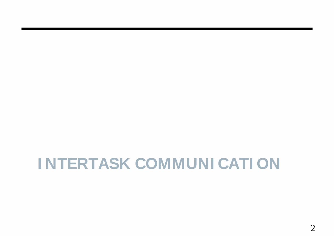
• Link could bel d– single direction, or 2-way
– no buffering ( rendezvous)fi ed si ed buffering– fixed sized buffering
– unbounded size buffering
process T process Rlink
m m’
ecei e(P m’)
3send(PT,m) receive(PT,m’)
Rendezvous
• When PT sends, it must wait until PR execute a receive. h i h i h f d• At that point the OS copies the messages from PT to PR, and
both then continue.• So the first of PT and PR to reach its send/receive command • So, the first of PT and PR to reach its send/receive command,
wait for the other
4
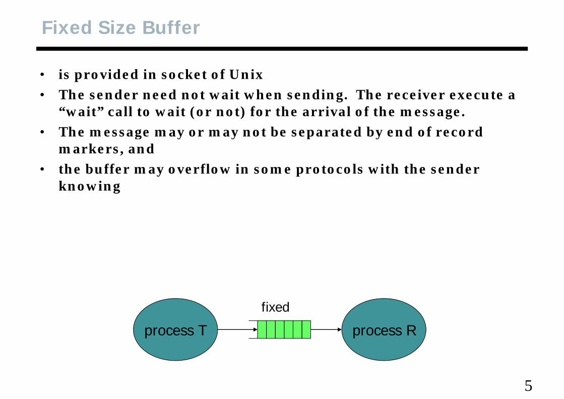
Fixed Size Buffer
• is provided in socket of Unixh d d i h di h i• The sender need not wait when sending. The receiver execute a
“wait” call to wait (or not) for the arrival of the message.• The message may or may not be separated by end of record • The message may or may not be separated by end of record
markers, and• the buffer may overflow in some protocols with the sender
knowing
fixed
process T process R
fixed
5
Mailbox
• fixed length buffers where the sender is forced to wait when the b ff i f llbuffer is full.
6
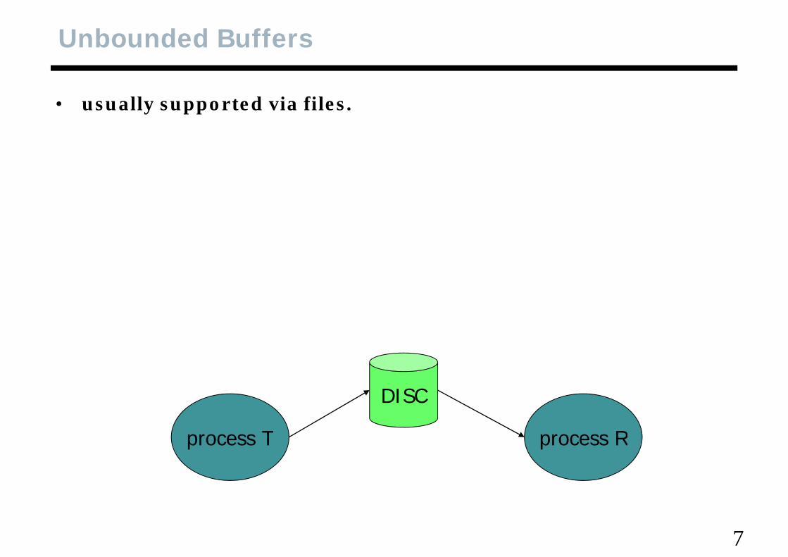
Unbounded Buffers
• usually supported via files.
T R
DISC
process T process R
7
IPC in Unix (1)
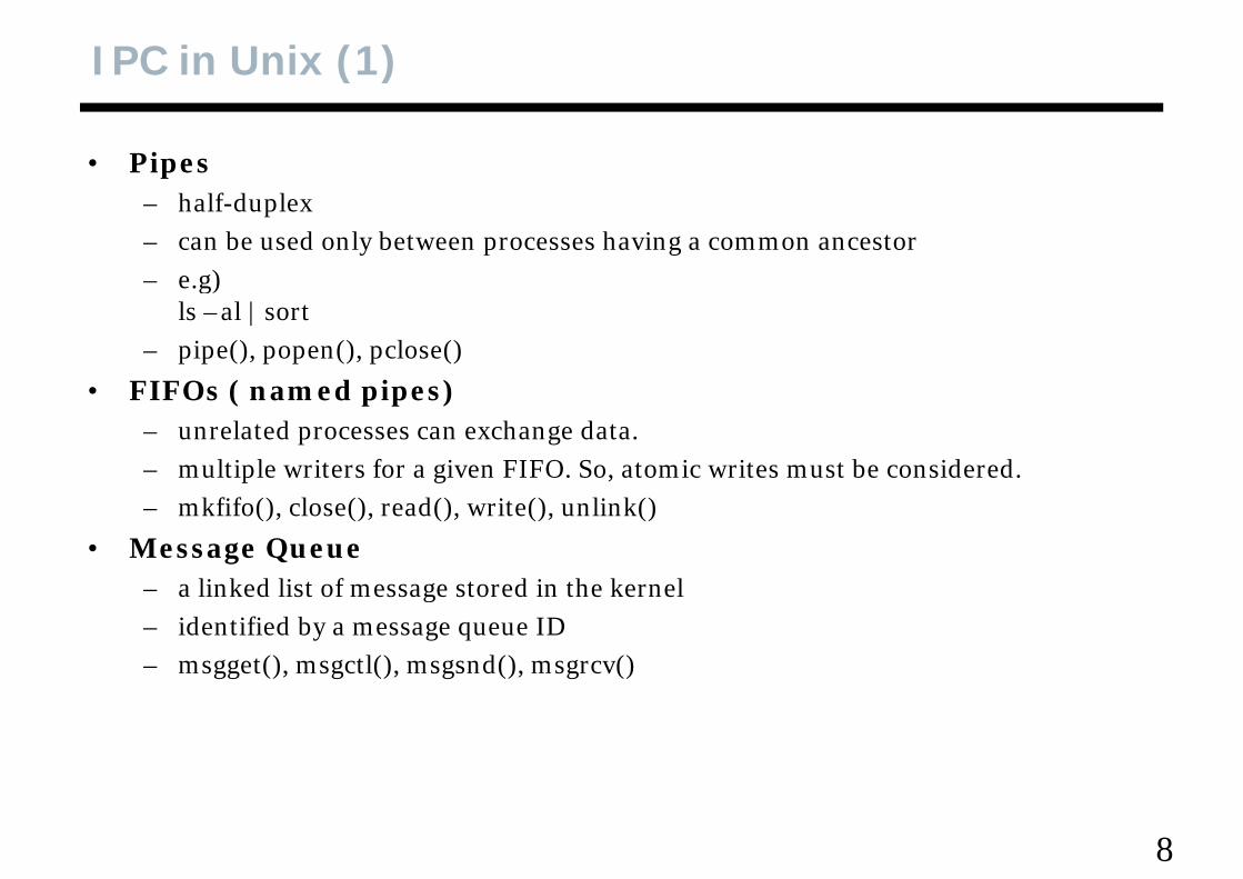
• Pipesh lf d l– half-duplex
– can be used only between processes having a common ancestor– e.g)g
ls –al | sort– pipe(), popen(), pclose()
• FIFOs ( named pipes)• FIFOs ( named pipes)– unrelated processes can exchange data.– multiple writers for a given FIFO. So, atomic writes must be considered. – mkfifo(), close(), read(), write(), unlink()
• Message Queuea linked list of message stored in the kernel– a linked list of message stored in the kernel
– identified by a message queue ID– msgget(), msgctl(), msgsnd(), msgrcv()
8
IPC in Unix (2)
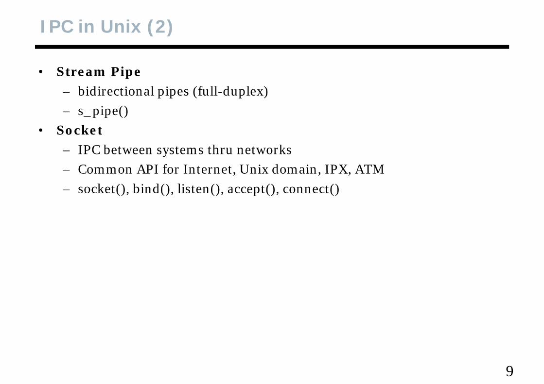
• Stream Pipeb d l f ll d l– bidirectional pipes (full-duplex)
– s_pipe()Socket• Socket– IPC between systems thru networks– Common API for Internet Unix domain IPX ATMCommon API for Internet, Unix domain, IPX, ATM– socket(), bind(), listen(), accept(), connect()
9
IPC in uCOSII
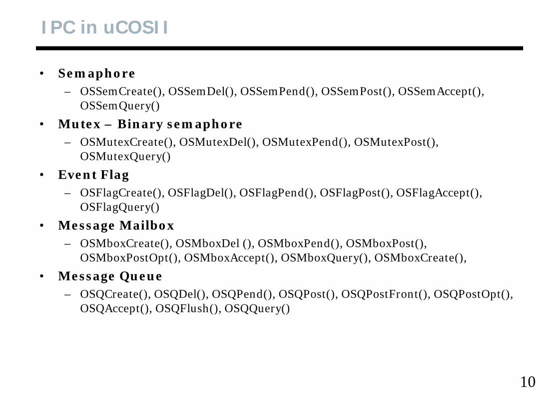
• SemaphoreOSS C t () OSS D l() OSS P d() OSS P t() OSS A t() – OSSemCreate(), OSSemDel(), OSSemPend(), OSSemPost(), OSSemAccept(), OSSemQuery()
• Mutex – Binary semaphore– OSMutexCreate(), OSMutexDel(), OSMutexPend(), OSMutexPost(),
OSMutexQuery()
• Event Flag• Event Flag– OSFlagCreate(), OSFlagDel(), OSFlagPend(), OSFlagPost(), OSFlagAccept(),
OSFlagQuery()
• Message Mailbox– OSMboxCreate(), OSMboxDel (), OSMboxPend(), OSMboxPost(),
OSMboxPostOpt(), OSMboxAccept(), OSMboxQuery(), OSMboxCreate(), p , p , Q y , ,
• Message Queue– OSQCreate(), OSQDel(), OSQPend(), OSQPost(), OSQPostFront(), OSQPostOpt(),
OSQAccept() OSQFlush() OSQQuery()OSQAccept(), OSQFlush(), OSQQuery()
10
Semaphore in uCOSII (1)
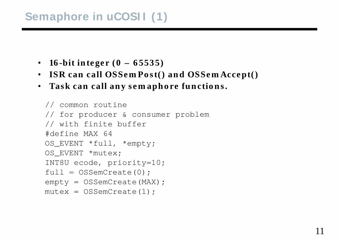
• 16-bit integer (0 – 65535)• ISR can call OSSemPost() and OSSemAccept()• Task can call any semaphore functions.
// common routine// common routine// for producer & consumer problem// with finite buffer#define MAX 64#define MAX 64OS_EVENT *full, *empty;OS_EVENT *mutex;INT8U ecode, priority=10;full = OSSemCreate(0);empty = OSSemCreate(MAX); mutex = OSSemCreate(1);
11
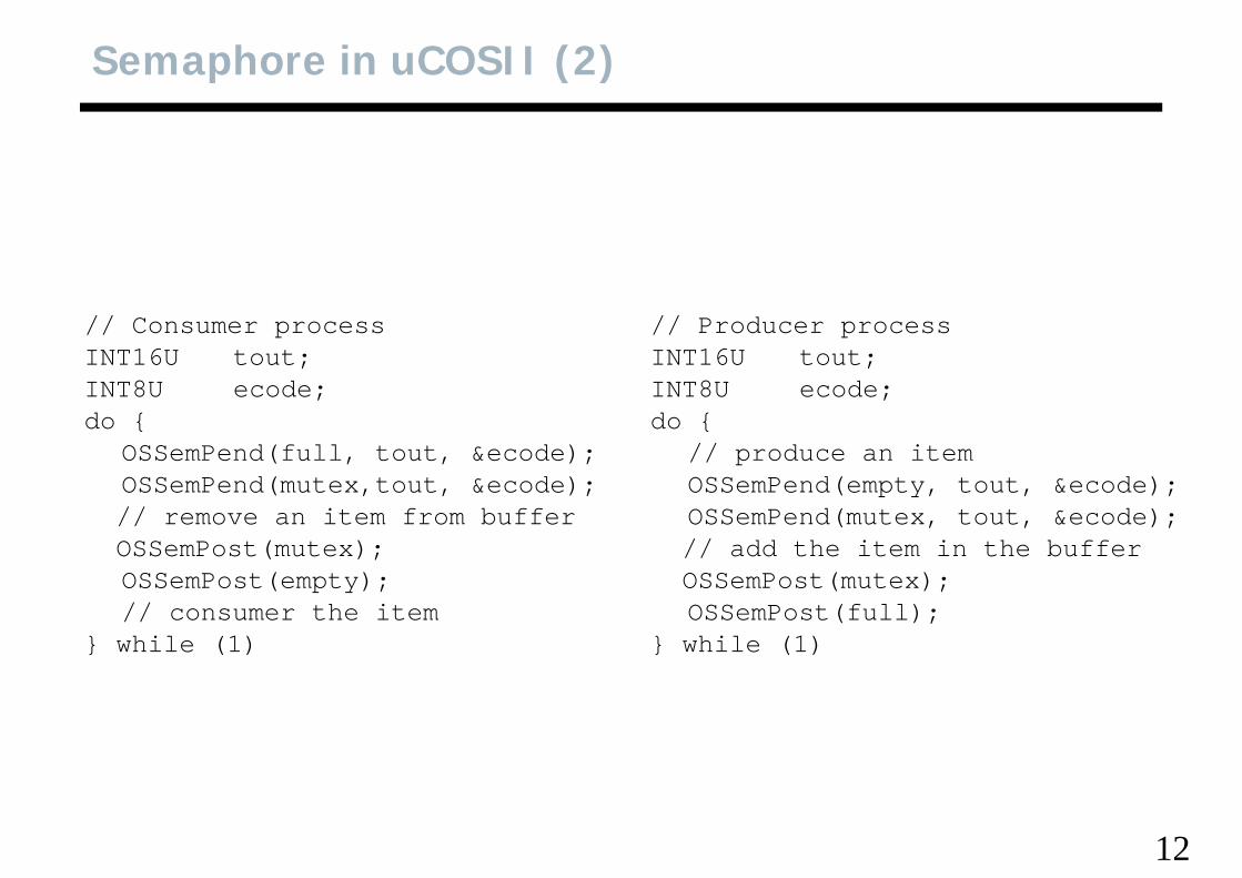
Semaphore in uCOSII (2)
// Consumer processINT16U tout;INT8U ecode;
// Producer processINT16U tout;INT8U ecode;INT8U ecode;
do {OSSemPend(full, tout, &ecode);OSSemPend(mutex tout &ecode);
INT8U ecode;do {
// produce an itemOSSemPend(empty tout &ecode);OSSemPend(mutex,tout, &ecode);
// remove an item from bufferOSSemPost(mutex);OSSemPost(empty);
OSSemPend(empty, tout, &ecode);OSSemPend(mutex, tout, &ecode);// add the item in the bufferOSSemPost(mutex);OSSemPost(empty);
// consumer the item} while (1)
OSSemPost(mutex);OSSemPost(full);
} while (1)
12
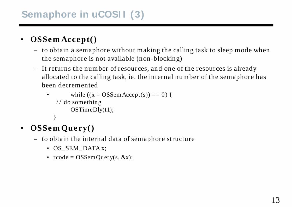
Semaphore in uCOSII (3)
• OSSemAccept()– to obtain a semaphore without making the calling task to sleep mode when
the semaphore is not available (non-blocking)– It returns the number of resources and one of the resources is already – It returns the number of resources, and one of the resources is already
allocated to the calling task, ie. the internal number of the semaphore has been decremented
hil (( ( )) ) {• while ((x = OSSemAccept(s)) == 0) {// do something
OSTimeDly(t1);}}
• OSSemQuery()to obtain the internal data of semaphore structure– to obtain the internal data of semaphore structure
• OS_SEM_DATA x;• rcode = OSSemQuery(s, &x);
13
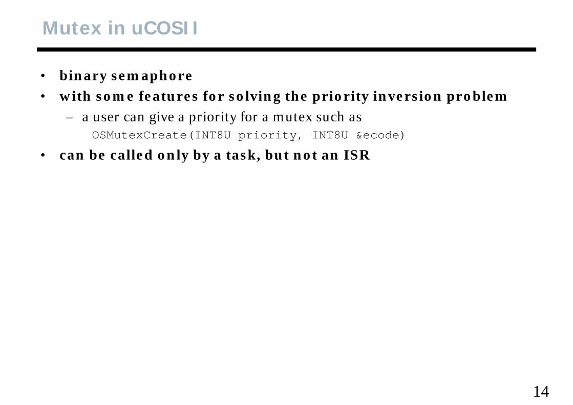
Mutex in uCOSII
• binary semaphorei h f f l i h i i i i bl• with some features for solving the priority inversion problem
– a user can give a priority for a mutex such asOSMutexCreate(INT8U priority INT8U &ecode)OSMutexCreate(INT8U priority, INT8U &ecode)
• can be called only by a task, but not an ISR
14
Event Flag in uCOSII
• ISR can call only OSFlagPost(), OSFlagAccept(), OSFlagAccept(), ll f hi h bl kiall of which are nonblocking
• A task can call all OSFlagxxx() system calls.• Easy to serialize a combination of events• Easy to serialize a combination of events
15
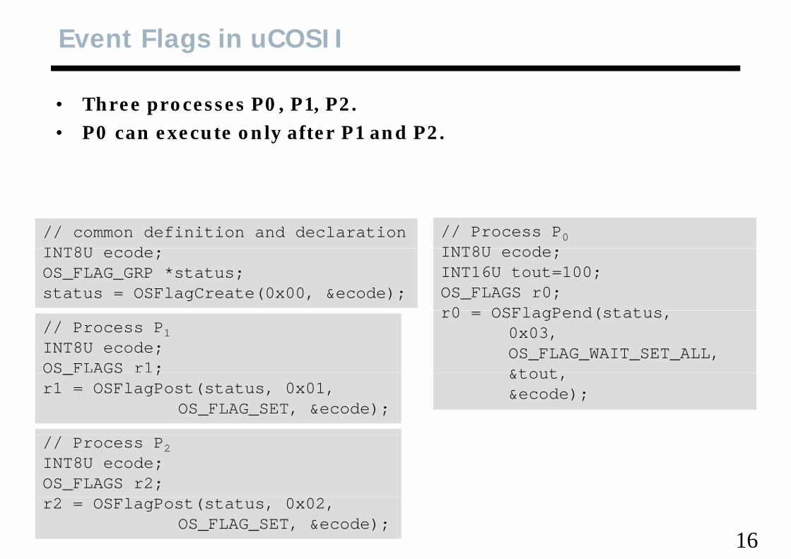
Event Flags in uCOSII
• Three processes P0, P1, P2. l f d• P0 can execute only after P1 and P2.
// common definition and declarationINT8U d
// Process P0INT8U dINT8U ecode;
OS_FLAG_GRP *status;status = OSFlagCreate(0x00, &ecode);
INT8U ecode;INT16U tout=100;OS_FLAGS r0;r0 OSFlagPend(status
// Process P1INT8U ecode;OS FLAGS r1;
r0 = OSFlagPend(status, 0x03, OS_FLAG_WAIT_SET_ALL,&toutOS_ GS ;
r1 = OSFlagPost(status, 0x01, OS_FLAG_SET, &ecode);
&tout,&ecode);
// Process P2INT8U ecode;OS_FLAGS r2;
16
r2 = OSFlagPost(status, 0x02, OS_FLAG_SET, &ecode);
Mailbox in UCOSII
• to send a pointer-sized variable to another taskh f h i i ifi li i• the usage of the pointer is specific to application
• ISR can call OSMboxPost(), OSMboxPostOpt(), OSMboxAccept() all of them are non-blocking callsOSMboxAccept(), all of them are non-blocking calls.
17
Message Queue in uCOSII
• To send pointer-sized variables to another taskh f h i i bl i li i ifi• The usage of the pointer variables is application specific
• ISR can call only OSQFlush(), OSQPost(), OSQPostFront(), OSQPostOpt() OSQAccept()OSQPostOpt(), OSQAccept()
• A Task can call any OSQxxxx() functions• Think it as a mailbox with multiple entries, or an array of p , y
mailboxes, but only one wait list associated with it.
18
C9S 2MC9S12
19
9S12 Architecture
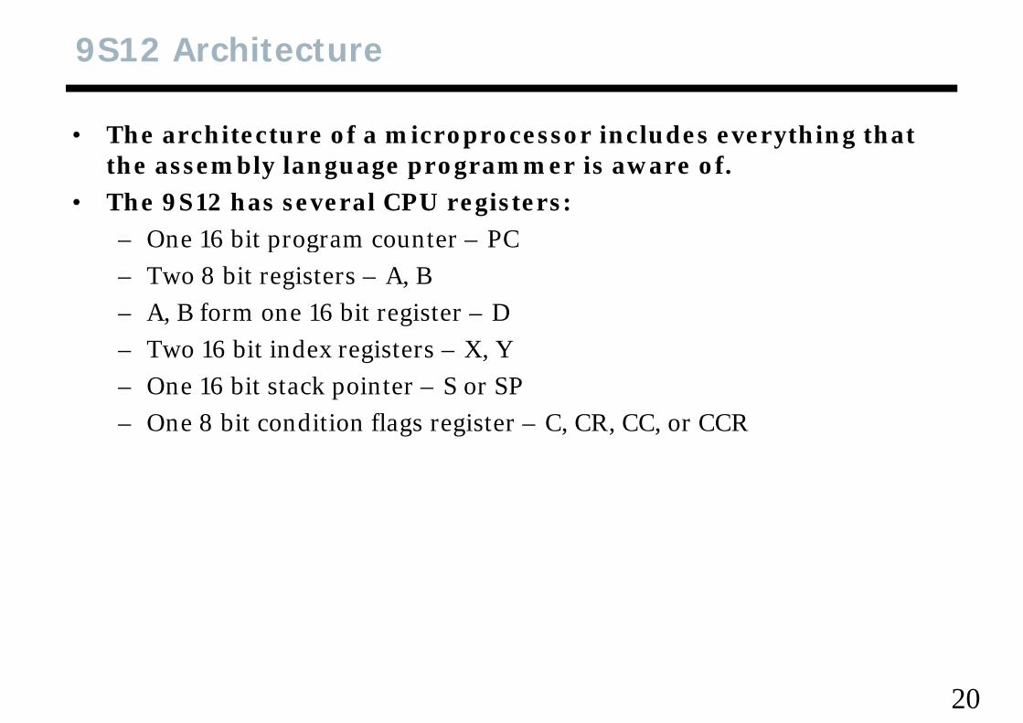
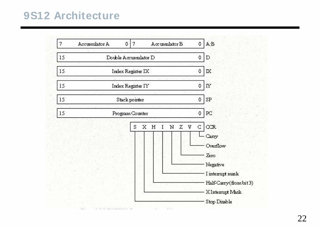
• The architecture of a microprocessor includes everything that th bl l i fthe assembly language programmer is aware of.
• The 9S12 has several CPU registers:– One 16 bit program counter – PC– One 16 bit program counter – PC– Two 8 bit registers – A, B– A, B form one 16 bit register – D, b g– Two 16 bit index registers – X, Y– One 16 bit stack pointer – S or SP– One 8 bit condition flags register – C, CR, CC, or CCR
20
Condition Register
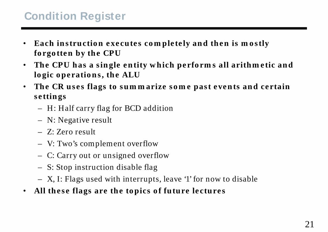
• Each instruction executes completely and then is mostly f tt b th CPUforgotten by the CPU
• The CPU has a single entity which performs all arithmetic and logic operations, the ALUlogic operations, the ALU
• The CR uses flags to summarize some past events and certain settings– H: Half carry flag for BCD addition– N: Negative result
Z Z l– Z: Zero result– V: Two’s complement overflow
C: Carry out or unsigned overflow– C: Carry out or unsigned overflow– S: Stop instruction disable flag– X I: Flags used with interrupts leave ‘1’ for now to disableX, I: Flags used with interrupts, leave 1 for now to disable
• All these flags are the topics of future lectures
21
9S12 Architecture
22
Memory Maps
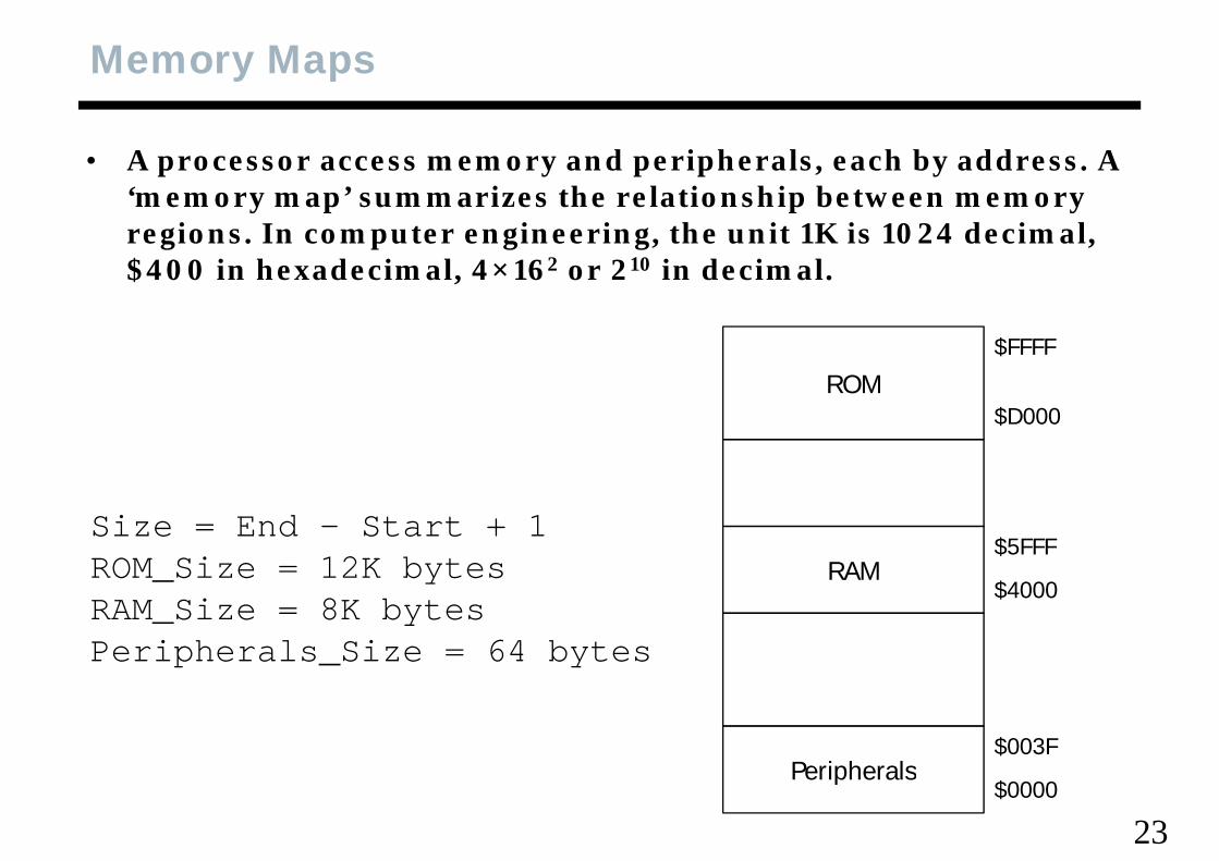
• A processor access memory and peripherals, each by address. A ‘ ’ i th l ti hi b t ‘memory map’ summarizes the relationship between memory regions. In computer engineering, the unit 1K is 1024 decimal, $400 in hexadecimal, 4×162 or 210 in decimal.
ROM$FFFF
ROM$D000
Size = End – Start + 1ROM Size = 12K bytes RAM
$5FFFROM_Size 12K bytesRAM_Size = 8K bytesPeripherals_Size = 64 bytes
RAM$4000
_
Peripherals$003F
23
Peripherals$0000
9S12 Architecture
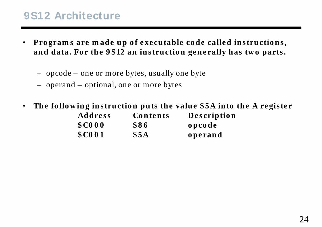
• Programs are made up of executable code called instructions, d d t F th 9S12 i t ti ll h t tand data. For the 9S12 an instruction generally has two parts.
– opcode – one or more bytes, usually one byteopcode one or more bytes, usually one byte– operand – optional, one or more bytes
• The following instruction puts the value $5A into the A registerAddress Contents Description$C000 $86 opcode$C000 $86 opcode$C001 $5A operand
24
9S12 Architecture, Concept
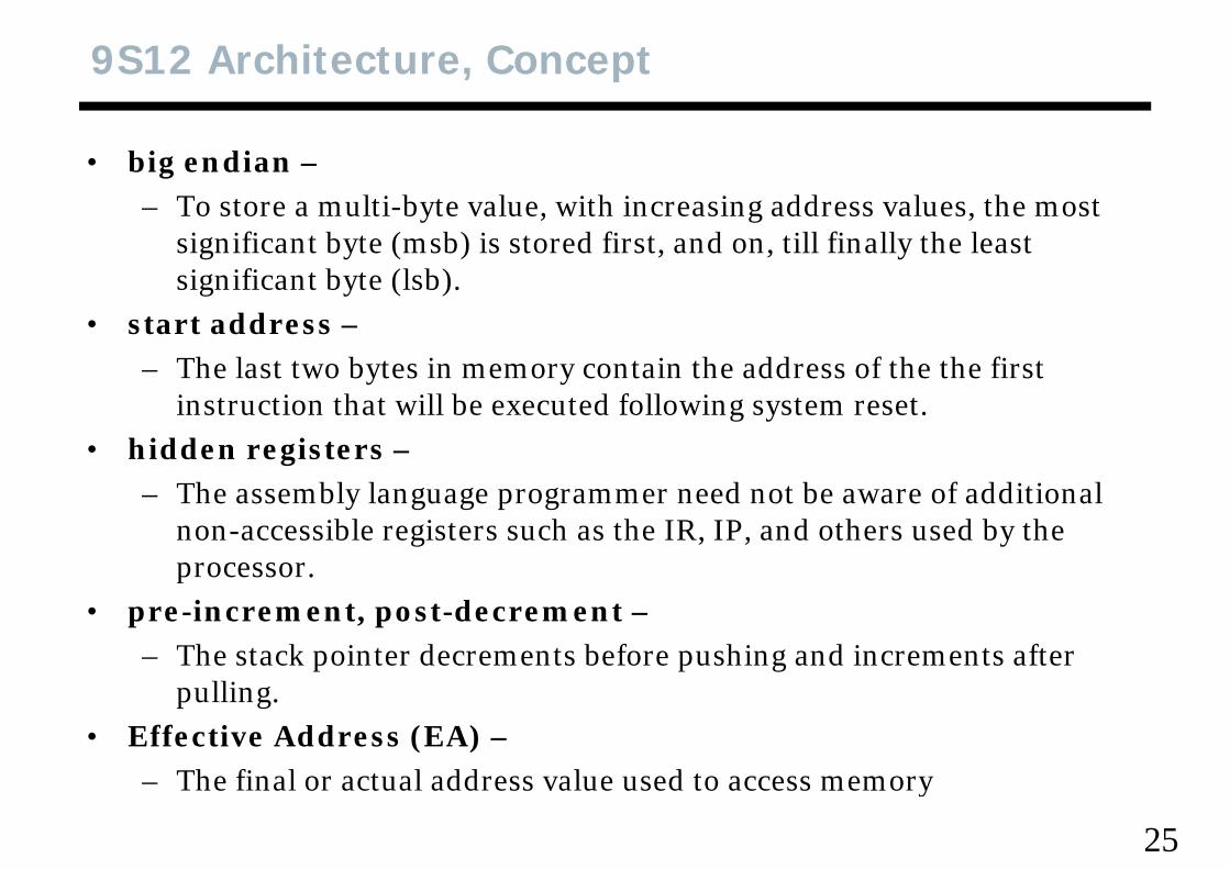
• big endian –l b l h dd l h– To store a multi-byte value, with increasing address values, the most
significant byte (msb) is stored first, and on, till finally the least significant byte (lsb).significant byte (lsb).
• start address –– The last two bytes in memory contain the address of the the first
instruction that will be executed following system reset.• hidden registers –
Th bl l d b f ddi i l – The assembly language programmer need not be aware of additional non-accessible registers such as the IR, IP, and others used by the processor.p
• pre-increment, post-decrement –– The stack pointer decrements before pushing and increments after
pulling. • Effective Address (EA) –
Th fi l t l dd l d t
25
– The final or actual address value used to access memory
9S12 Architecture
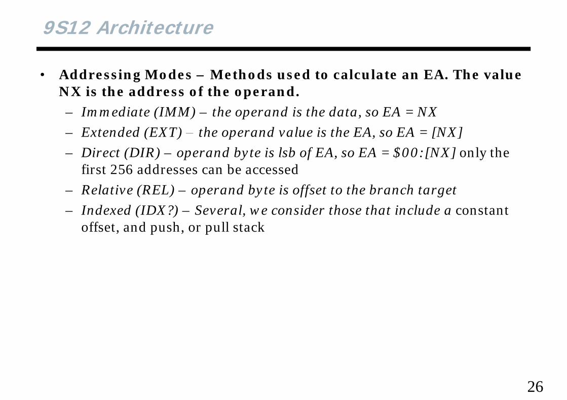
• Addressing Modes – Methods used to calculate an EA. The value NX i th dd f th dNX is the address of the operand.– Immediate (IMM) – the operand is the data, so EA = NX– Extended (EXT) – the operand value is the EA so EA = [NX]– Extended (EXT) the operand value is the EA, so EA = [NX]– Direct (DIR) – operand byte is lsb of EA, so EA = $00:[NX] only the
first 256 addresses can be accessed– Relative (REL) – operand byte is offset to the branch target– Indexed (IDX?) – Several, we consider those that include a constant
ff d h ll koffset, and push, or pull stack
26
9S12 Architecture
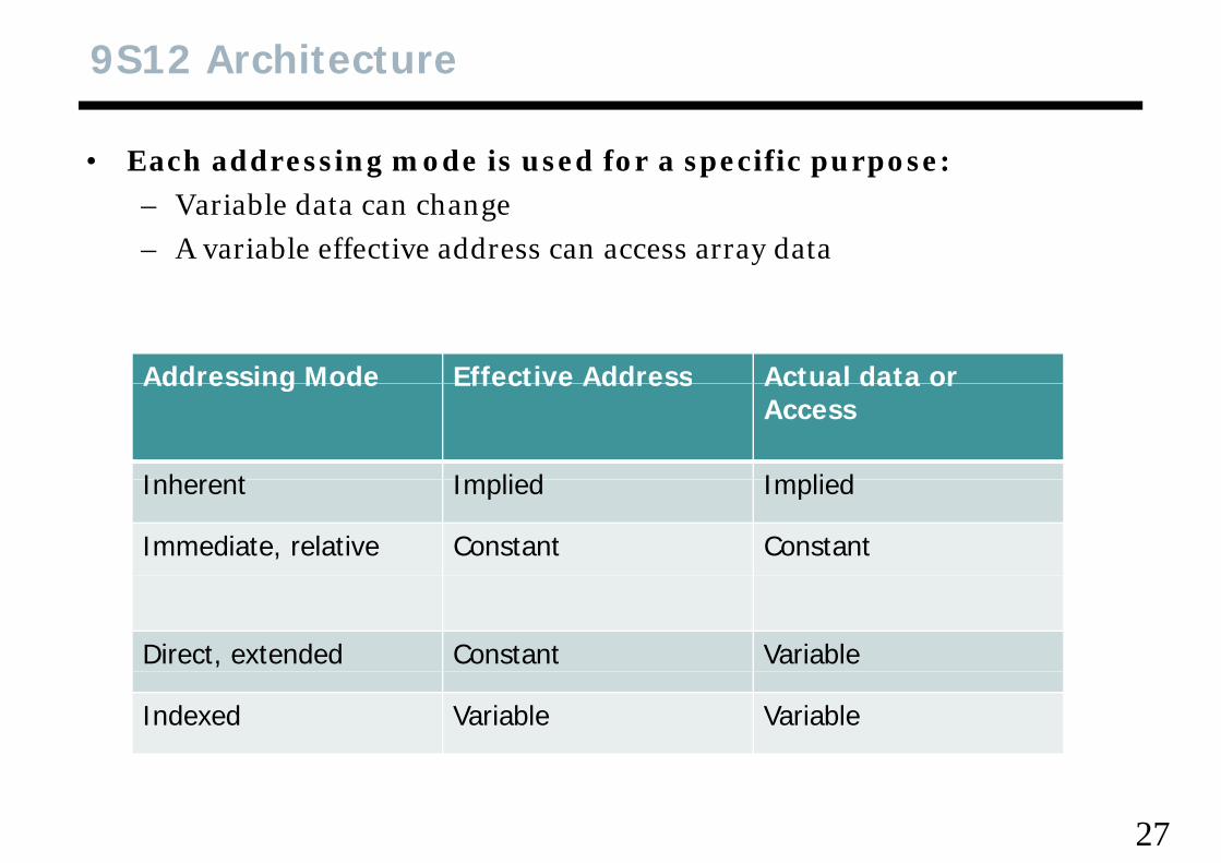
• Each addressing mode is used for a specific purpose:bl d h– Variable data can change
– A variable effective address can access array data
Addressing Mode Effective Address Actual data orAddressing Mode Effective Address Actual data or Access
Inherent Implied ImpliedInherent Implied Implied
Immediate, relative Constant Constant
Direct, extended Constant Variable
Indexed Variable Variable
27
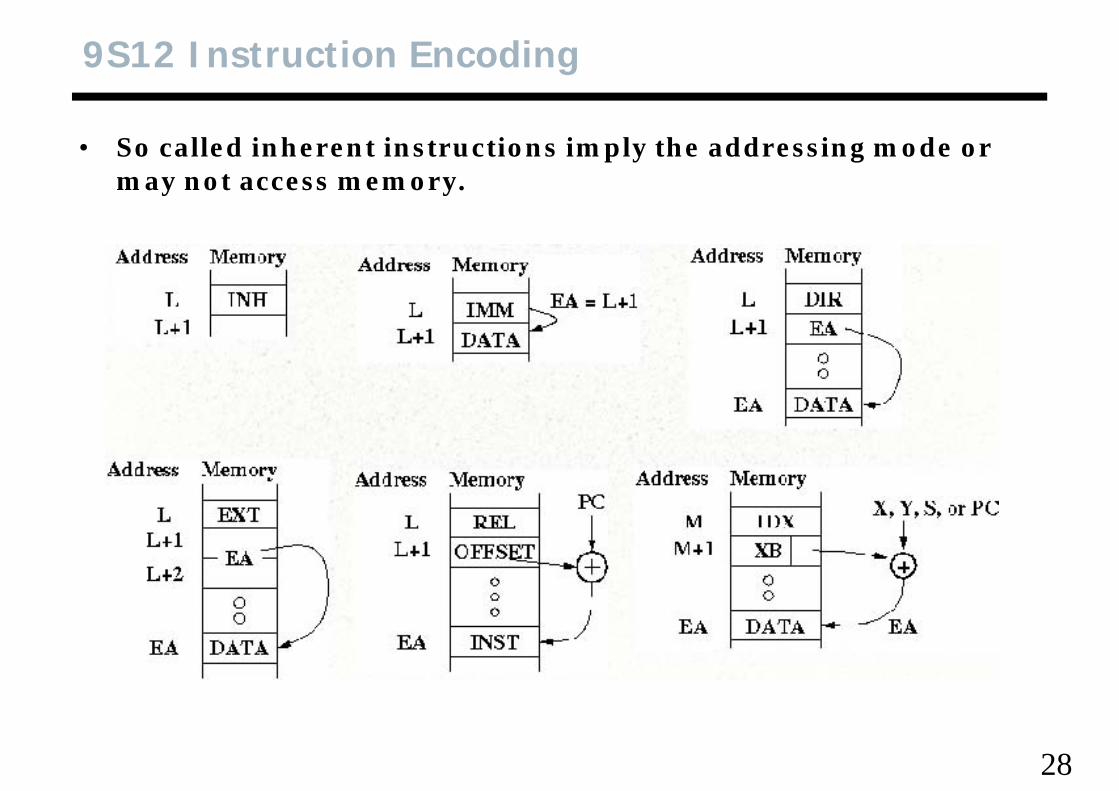
9S12 Instruction Encoding
• So called inherent instructions imply the addressing mode or t may not access memory.
28
Quick Check
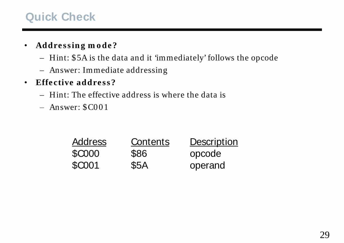
• Addressing mode?h d d d l f ll h d– Hint: $5A is the data and it ‘immediately’ follows the opcode
– Answer: Immediate addressingEffective address?• Effective address?– Hint: The effective address is where the data is– Answer: $C001Answer: $C001
Address Contents Description$C000 $86 opcode$C001 $5A d$C001 $5A operand
29
9S12 Architecture
• mnemonic –h f l h– a short group of letters that suggest an action, a given mnemonic may
refer to several possible instructions, based on the addressing mode used. used.
– Consider the mnemonic, ‘ldaa’ which means, ‘load a byte value into the A register. The addressing mode indicates where the value will be f d i found in memory.
• encoding –• encoding – the first part of an instruction is called the opcode.
The way an opcode conveys an action and the addressing mode(s) is called the encoding.
30
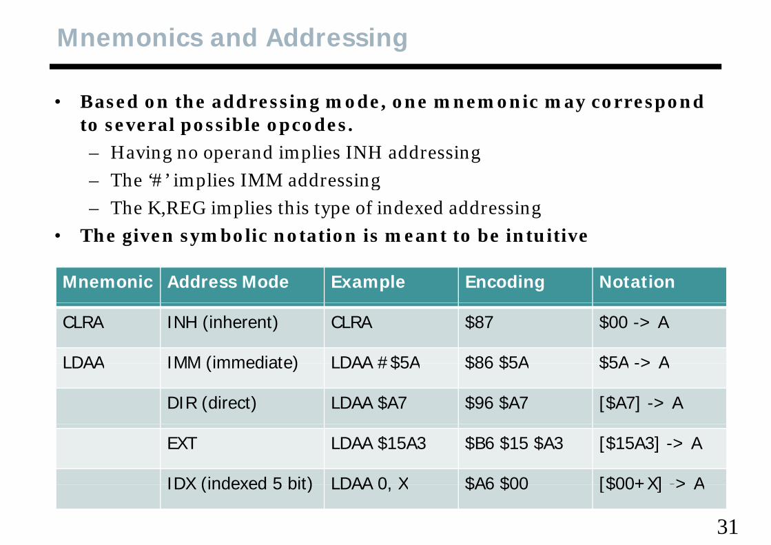
Mnemonics and Addressing
• Based on the addressing mode, one mnemonic may correspond t l ibl dto several possible opcodes.– Having no operand implies INH addressing– The ‘#’ implies IMM addressing– The # implies IMM addressing– The K,REG implies this type of indexed addressing
• The given symbolic notation is meant to be intuitiveg y
Mnemonic Address Mode Example Encoding Notation
CLRA INH (inherent) CLRA $87 $00 -> A
LDAA IMM (immediate) LDAA #$5A $86 $5A $5A -> ALDAA IMM (immediate) LDAA #$5A $86 $5A $5A -> A
DIR (direct) LDAA $A7 $96 $A7 [$A7] -> A
EXT LDAA $15A3 $B6 $15 $A3 [$15A3] -> A
IDX (indexed 5 bit) LDAA 0 X $A6 $00 [$00+X] -> A
31
IDX (indexed 5 bit) LDAA 0, X $A6 $00 [$00+X] > A
Index Addressing Postbyte Code
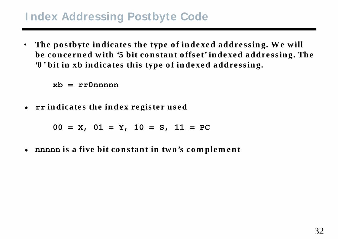
• The postbyte indicates the type of indexed addressing. We will b d ith ‘5 bit t t ff t’ i d d dd i Th be concerned with ‘5 bit constant offset’ indexed addressing. The ‘0’ bit in xb indicates this type of indexed addressing.
xb = rr0nnnnn
• rr indicates the index register used• rr indicates the index register used
00 = X, 01 = Y, 10 = S, 11 = PC
• nnnnn is a five bit constant in two’s complement
32
Calculating the 8 Bit Branch Offset
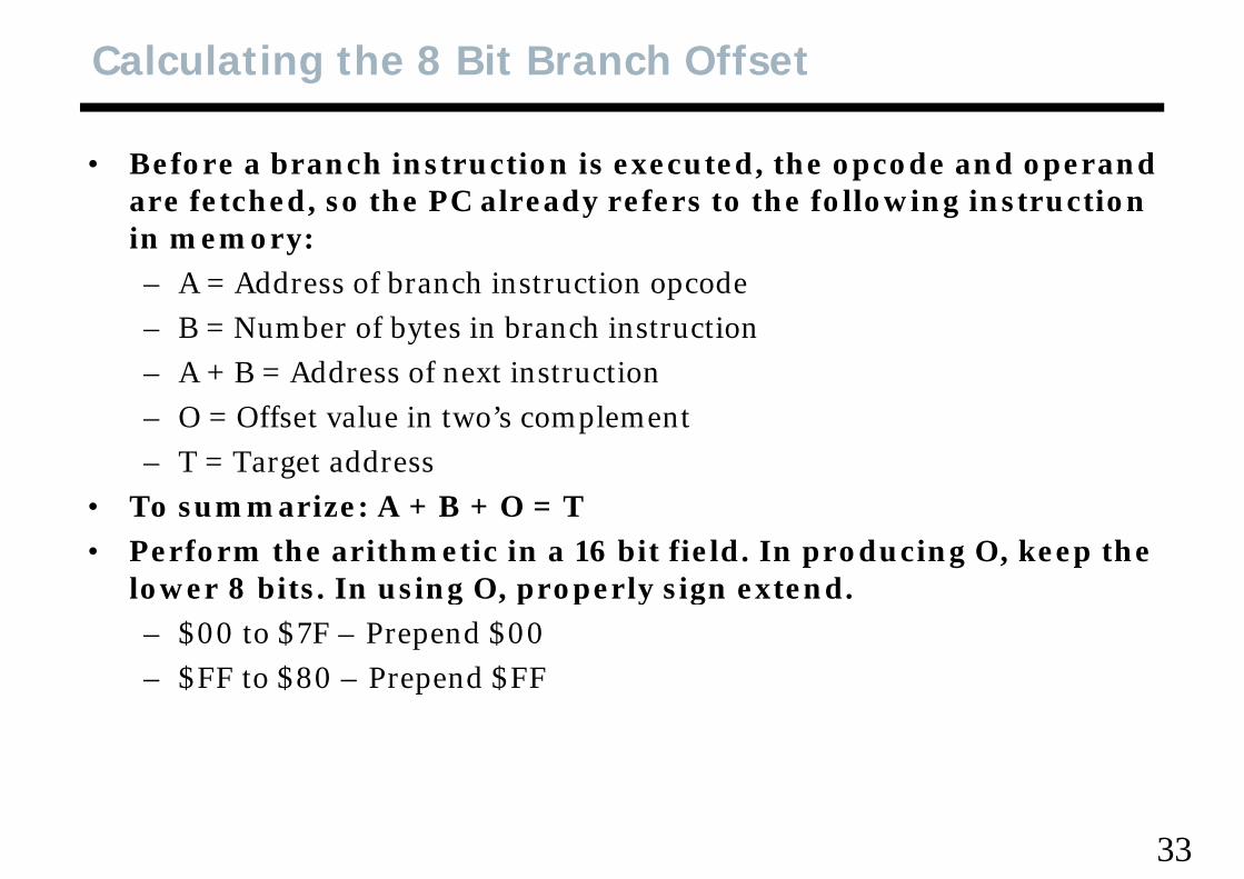
• Before a branch instruction is executed, the opcode and operand f t h d th PC l d f t th f ll i i t ti are fetched, so the PC already refers to the following instruction
in memory:– A = Address of branch instruction opcodeA Address of branch instruction opcode– B = Number of bytes in branch instruction– A + B = Address of next instruction– O = Offset value in two’s complement– T = Target address
• To summarize: A + B + O = T• Perform the arithmetic in a 16 bit field. In producing O, keep the
lower 8 bits In using O properly sign extendlower 8 bits. In using O, properly sign extend.– $00 to $7F – Prepend $00– $FF to $80 – Prepend $FF$FF to $80 Prepend $FF
33
9S12 Assembler
• An assembler converts assembly language source code files, ith t i t di t f ll d bj t fil either to an intermediate form called an object file, or an
executable file.• Some processors such as the Intel 8086 have several assemblers Some processors such as the Intel 8086 have several assemblers
to choose from, each with a variation in syntax.• Thankfully, nearly all assemblers for the 9S12 and predecessors
f ll di i l f ( i h i k d ddi i ) follow a traditional format (with quirks and oddities) documented in Motorola/Freescale literature.
34
9S12 Assembler Syntax
• symbol – a name for a valuel b l f dd l• label – a name for an address value
• Rules to keep in mind for symbols:A s mbol can include letters (A Z a ) underscores periods numbers– A symbol can include letters (A-Z, a-z), underscores, periods, numbers
– The first character must not be a number– Generated symbols start with an underscore While ‘legal’ avoid Generated symbols start with an underscore. While legal avoid
defining labels that start with an underscore– Use of a following colon is optional in defining a symbol, the following
colon will be ignored.– Decimal numbers are assumed by default
Th ‘$’ b l i di h d i l h ‘%’ b l i di bi – The ‘$’ symbol indicates hexadecimal, the ‘%’ symbol indicates binary, the ‘@’ symbol indicates octal
35
9S12 Assembler Syntax
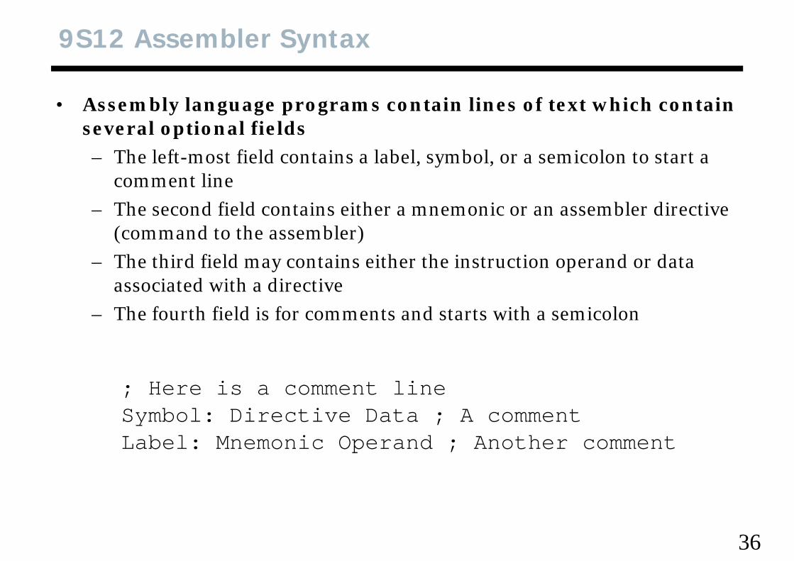
• Assembly language programs contain lines of text which contain l ti l fi ldseveral optional fields
– The left-most field contains a label, symbol, or a semicolon to start a comment linecomment line
– The second field contains either a mnemonic or an assembler directive (command to the assembler)
– The third field may contains either the instruction operand or data associated with a directiveThe fourth field is for comments and starts with a semicolon– The fourth field is for comments and starts with a semicolon
; Here is a comment lineSymbol: Directive Data ; A commentL b l M i O d A th tLabel: Mnemonic Operand ; Another comment
36
Assembly Language Sections
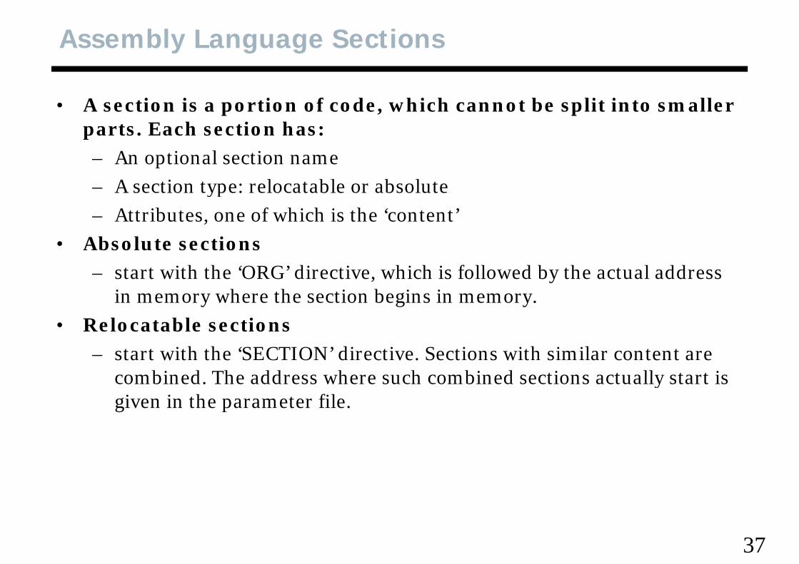
• A section is a portion of code, which cannot be split into smaller t E h ti hparts. Each section has:
– An optional section name– A section type: relocatable or absolute– A section type: relocatable or absolute– Attributes, one of which is the ‘content’
• Absolute sections – start with the ‘ORG’ directive, which is followed by the actual address
in memory where the section begins in memory.• Relocatable sections
– start with the ‘SECTION’ directive. Sections with similar content are combined The address where such combined sections actually start is combined. The address where such combined sections actually start is given in the parameter file.
37
Absolute Assembler Source Code
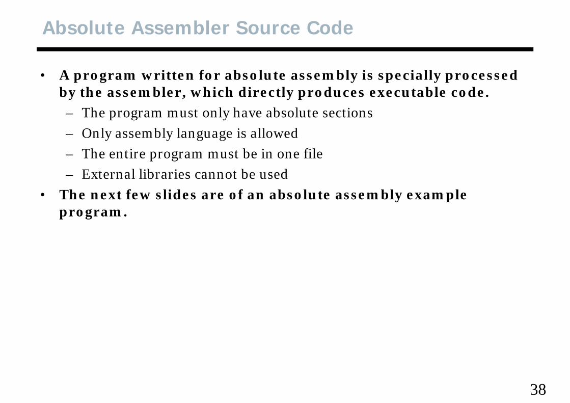
• A program written for absolute assembly is specially processed b th bl hi h di tl d t bl dby the assembler, which directly produces executable code.– The program must only have absolute sections– Only assembly language is allowed– Only assembly language is allowed– The entire program must be in one file– External libraries cannot be usedb b
• The next few slides are of an absolute assembly example program.
38
9S12 Assembler Example
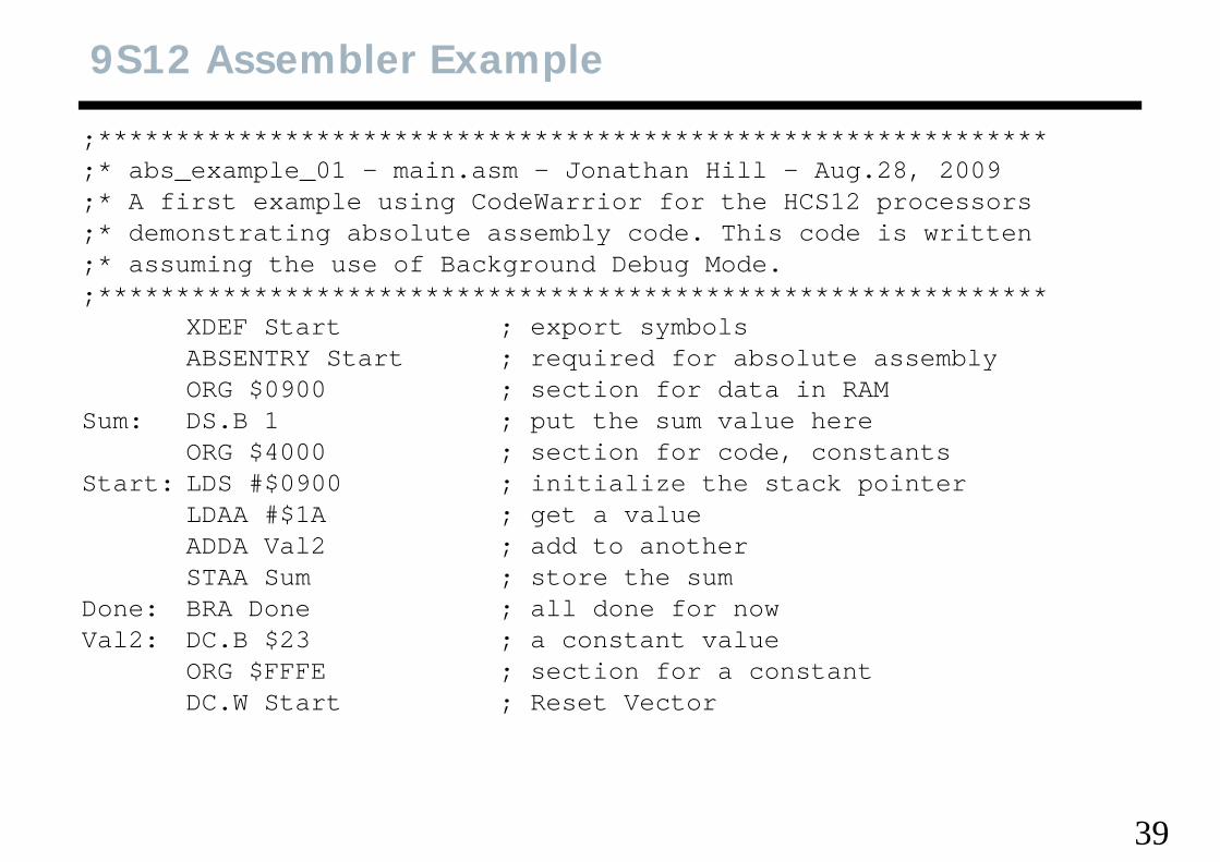
;*************************************************************;* abs_example_01 - main.asm - Jonathan Hill - Aug.28, 2009;* A first example using CodeWarrior for the HCS12 processors;* demonstrating absolute assembly code. This code is written;* assuming the use of Background Debug Mode.*************************************************************;*************************************************************
XDEF Start ; export symbolsABSENTRY Start ; required for absolute assemblyORG $0900 ti f d t i RAMORG $0900 ; section for data in RAM
Sum: DS.B 1 ; put the sum value hereORG $4000 ; section for code, constants
St t LDS #$0900 i iti li th t k i tStart: LDS #$0900 ; initialize the stack pointerLDAA #$1A ; get a valueADDA Val2 ; add to anotherSTAA Sum ; store the sumSTAA Sum ; store the sum
Done: BRA Done ; all done for nowVal2: DC.B $23 ; a constant value
ORG $FFFE ; section for a constantORG $FFFE ; section for a constantDC.W Start ; Reset Vector
39
9S12 Directives
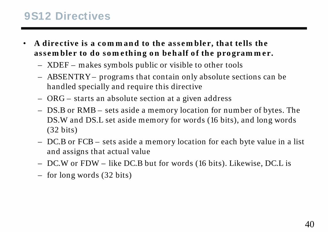
• A directive is a command to the assembler, that tells the bl t d thi b h lf f th assembler to do something on behalf of the programmer.
– XDEF – makes symbols public or visible to other tools– ABSENTRY – programs that contain only absolute sections can be – ABSENTRY – programs that contain only absolute sections can be
handled specially and require this directive– ORG – starts an absolute section at a given address– DS.B or RMB – sets aside a memory location for number of bytes. The
DS.W and DS.L set aside memory for words (16 bits), and long words (32 bits)(32 bits)
– DC.B or FCB – sets aside a memory location for each byte value in a list and assigns that actual valueg
– DC.W or FDW – like DC.B but for words (16 bits). Likewise, DC.L is – for long words (32 bits)
40
Hand Assembly So Far
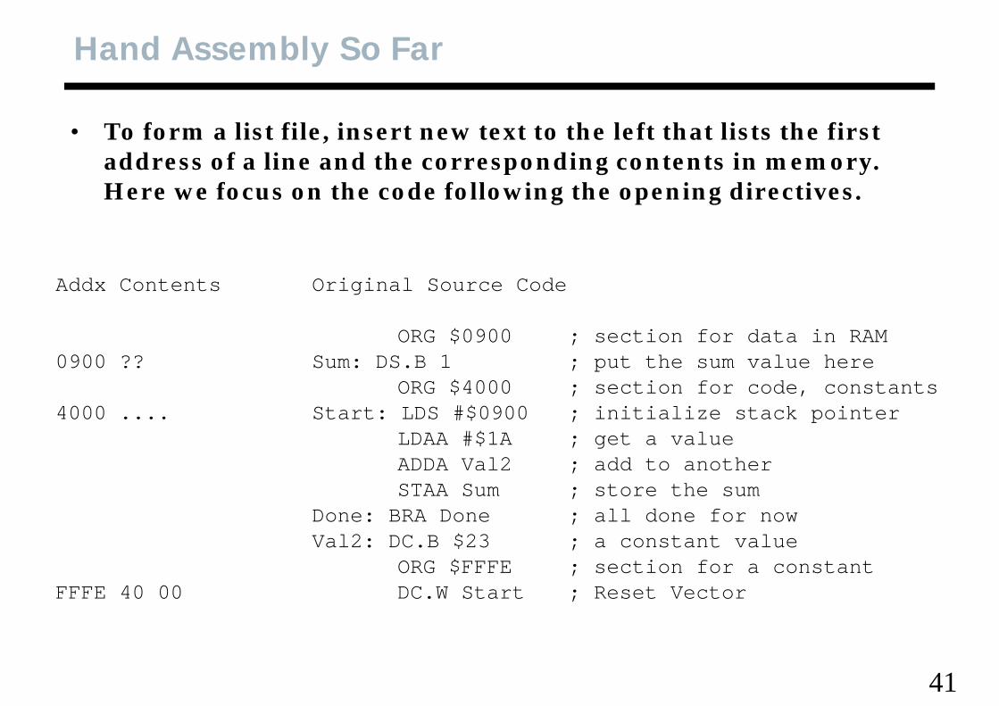
• To form a list file, insert new text to the left that lists the first dd f li d th di t t i address of a line and the corresponding contents in memory.
Here we focus on the code following the opening directives.
Addx Contents Original Source Code
ORG $0900 ; section for data in RAM0900 ?? Sum: DS.B 1 ; put the sum value here
ORG $4000 ; section for code, constantsORG $4000 ; section for code, constants4000 .... Start: LDS #$0900 ; initialize stack pointer
LDAA #$1A ; get a valueADDA Val2 ; add to another;STAA Sum ; store the sum
Done: BRA Done ; all done for nowVal2: DC.B $23 ; a constant value;
ORG $FFFE ; section for a constantFFFE 40 00 DC.W Start ; Reset Vector
41
9S12 Assembly Syntax
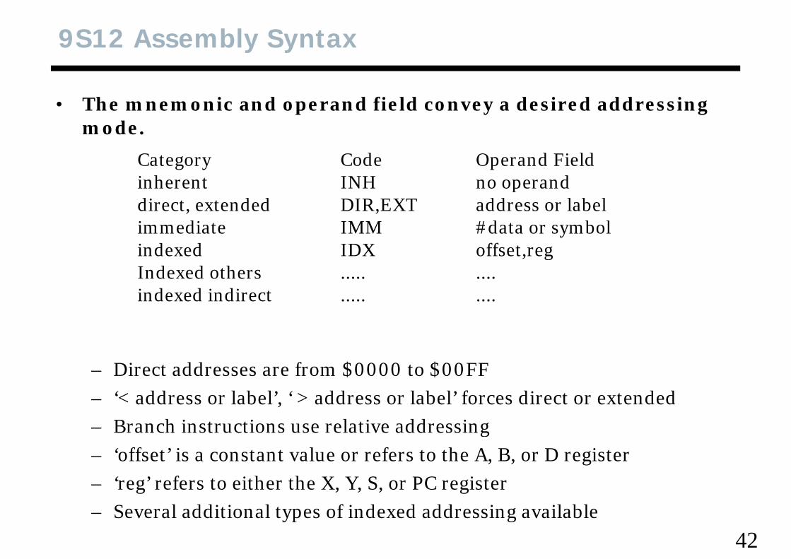
• The mnemonic and operand field convey a desired addressing dmode.
Category Code Operand Fieldinherent INH no operandinherent INH no operanddirect, extended DIR,EXT address or labelimmediate IMM #data or symbolindexed IDX offset regindexed IDX offset,regIndexed others ..... ....indexed indirect ..... ....
– Direct addresses are from $0000 to $00FFDirect addresses are from $0000 to $00FF– ‘< address or label’, ‘ > address or label’ forces direct or extended– Branch instructions use relative addressingg– ‘offset’ is a constant value or refers to the A, B, or D register– ‘reg’ refers to either the X, Y, S, or PC register
42– Several additional types of indexed addressing available
Hand Assembly First Pass
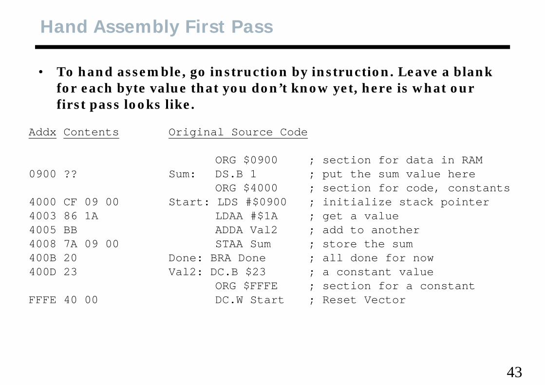
• To hand assemble, go instruction by instruction. Leave a blank f h b t l th t d ’t k t h i h t for each byte value that you don’t know yet, here is what our first pass looks like.
dd i i l dAddx Contents Original Source Code
ORG $0900 ; section for data in RAM0900 ?? S DS B 1 t th l h0900 ?? Sum: DS.B 1 ; put the sum value here
ORG $4000 ; section for code, constants4000 CF 09 00 Start: LDS #$0900 ; initialize stack pointer4003 86 1A LDAA #$1A t l4003 86 1A LDAA #$1A ; get a value4005 BB ADDA Val2 ; add to another4008 7A 09 00 STAA Sum ; store the sum400B 20 Done: BRA Done ; all done for now400B 20 Done: BRA Done ; all done for now400D 23 Val2: DC.B $23 ; a constant value
ORG $FFFE ; section for a constantFFFE 40 00 DC W Start ; Reset VectorFFFE 40 00 DC.W Start ; Reset Vector
43
Hand Assembly First Pass
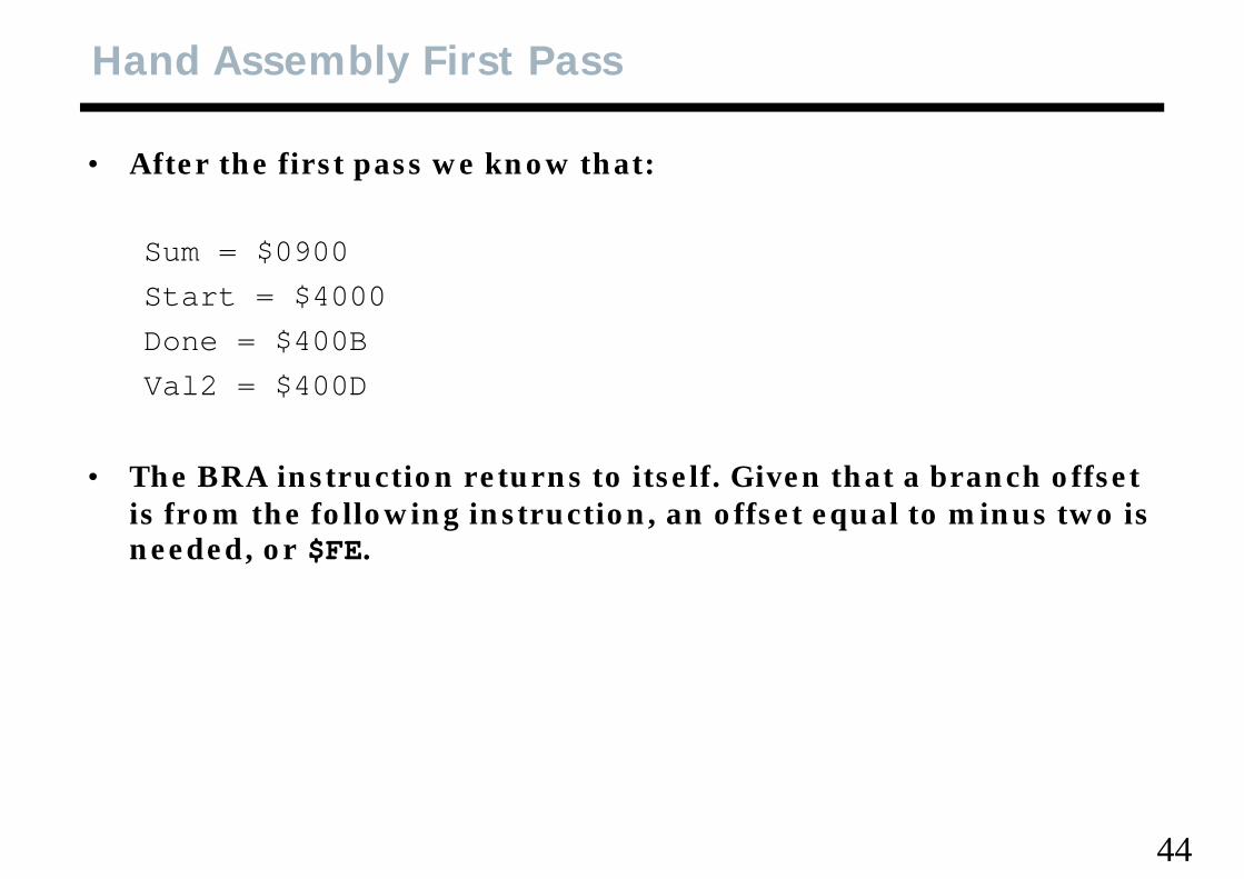
• After the first pass we know that:
Sum = $0900Start $4000Start = $4000Done = $400BVal2 = $400DVal2 $400D
• The BRA instruction returns to itself. Given that a branch offset is from the following instruction, an offset equal to minus two is needed, or $FE.
44
Hand Assembly Second Pass
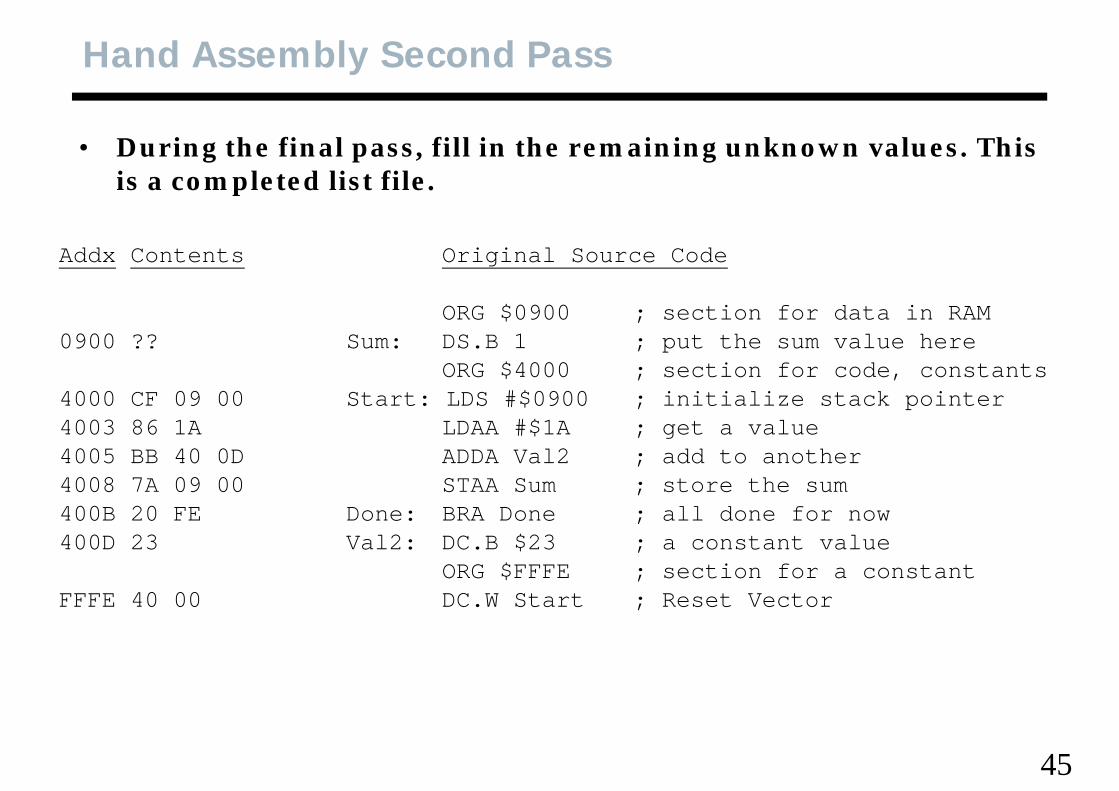
• During the final pass, fill in the remaining unknown values. This i l t d li t filis a completed list file.
Addx Contents Original Source Codeg
ORG $0900 ; section for data in RAM0900 ?? Sum: DS.B 1 ; put the sum value herep
ORG $4000 ; section for code, constants4000 CF 09 00 Start: LDS #$0900 ; initialize stack pointer4003 86 1A LDAA #$1A ; get a value4005 BB 40 0D ADDA Val2 ; add to another4008 7A 09 00 STAA Sum ; store the sum400B 20 FE Done: BRA Done ; all done for now400D 23 Val2: DC.B $23 ; a constant value
ORG $FFFE ; section for a constantFFFE 40 00 DC.W Start ; Reset Vector
45
Quick Check
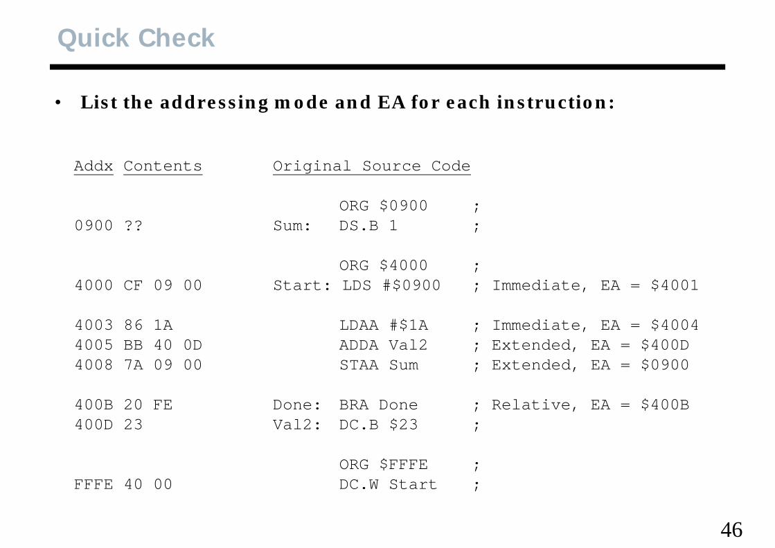
• List the addressing mode and EA for each instruction:
Addx Contents Original Source Code
ORG $0900 ;0900 ?? Sum: DS.B 1 ;
ORG $4000 ;4000 CF 09 00 Start: LDS #$0900 ; Immediate, EA = $4001
4003 86 1A LDAA #$1A ; Immediate, EA = $40044005 BB 40 0D ADDA Val2 ; Extended, EA = $400D4008 7A 09 00 STAA Sum ; Extended EA = $09004008 7A 09 00 STAA Sum ; Extended, EA = $0900
400B 20 FE Done: BRA Done ; Relative, EA = $400B400D 23 Val2: DC B $23 ;400D 23 Val2: DC.B $23 ;
ORG $FFFE ;FFFE 40 00 DC.W Start ;
46
FFFE 40 00 DC.W Start ;
Hand Assembly Second Pass
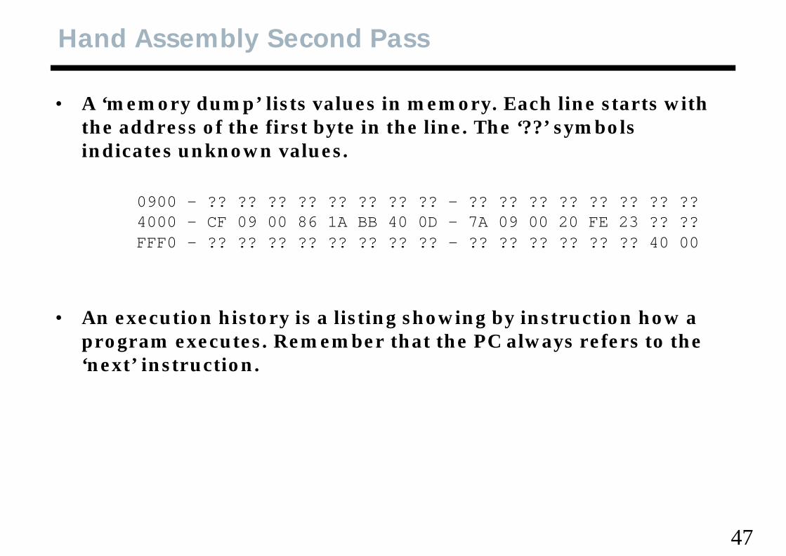
• A ‘memory dump’ lists values in memory. Each line starts with th dd f th fi t b t i th li Th ‘??’ b l the address of the first byte in the line. The ‘??’ symbols indicates unknown values.
0900 - ?? ?? ?? ?? ?? ?? ?? ?? - ?? ?? ?? ?? ?? ?? ?? ??4000 - CF 09 00 86 1A BB 40 0D - 7A 09 00 20 FE 23 ?? ??FFF0 - ?? ?? ?? ?? ?? ?? ?? ?? - ?? ?? ?? ?? ?? ?? 40 00FFF0 ?? ?? ?? ?? ?? ?? ?? ?? ?? ?? ?? ?? ?? ?? 40 00
• An execution history is a listing showing by instruction how a program executes. Remember that the PC always refers to the ‘next’ instruction.next instruction.
47
Execution History
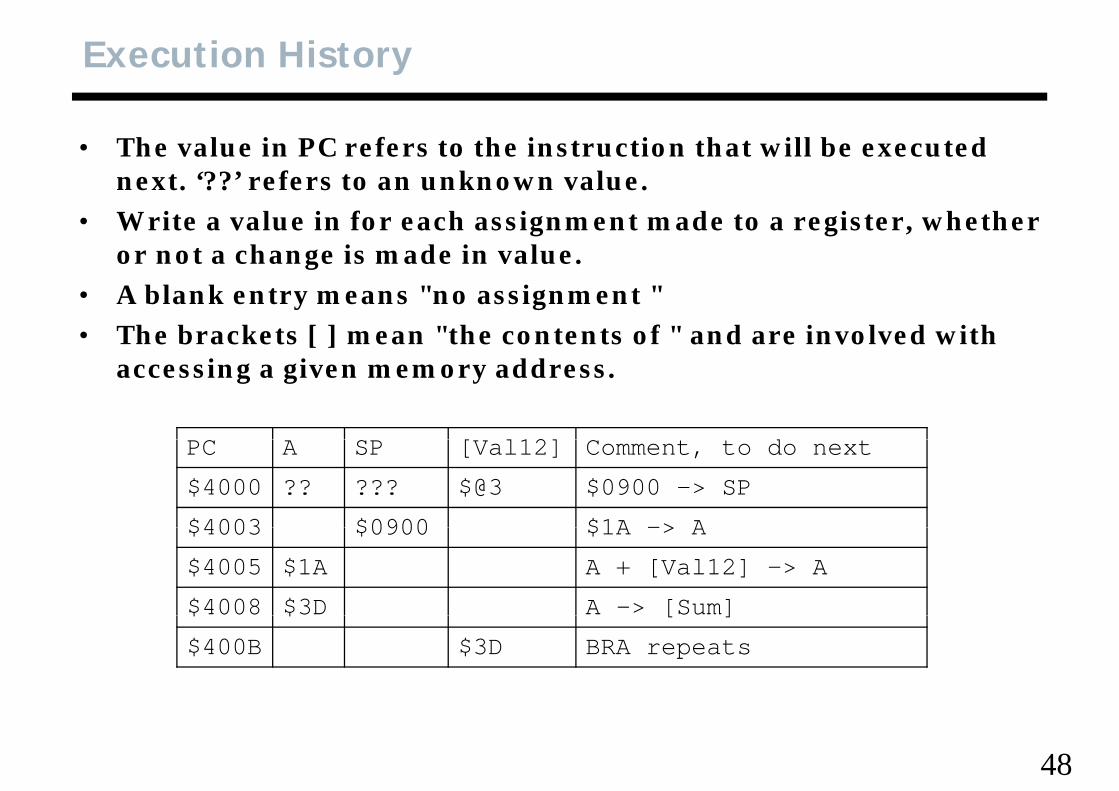
• The value in PC refers to the instruction that will be executed t ‘??’ f t k lnext. ‘??’ refers to an unknown value.
• Write a value in for each assignment made to a register, whether or not a change is made in value.or not a change is made in value.
• A blank entry means "no assignment "• The brackets [ ] mean "the contents of " and are involved with
accessing a given memory address.
[ l12] dPC A SP [Val12] Comment, to do next
$4000 ?? ??? $@3 $0900 -> SP
$4003 $0900 $1A -> A$4003 $0900 $1A -> A
$4005 $1A A + [Val12] -> A
$4008 $3D A -> [Sum]$ $ [ ]
$400B $3D BRA repeats
48
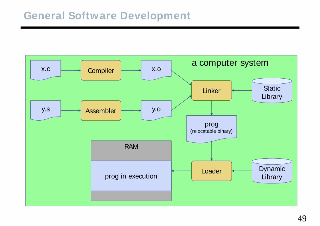
General Software Development
Compilerx.c x.oa computer system
Linker StaticLibrary
Assemblery.s y.o
progprog(relocatable binary)
RAM
Loader DynamicLibraryprog in execution Libraryprog in execution
49
Development in Embedded Systems
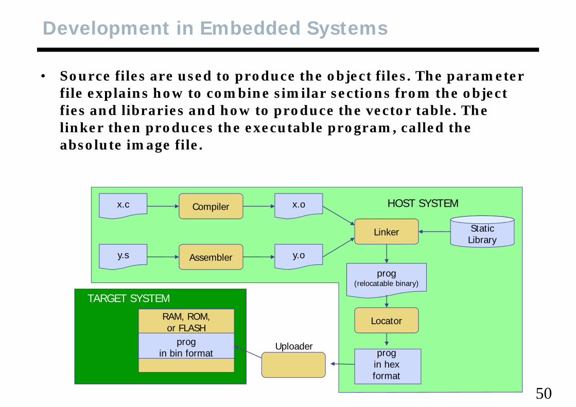
• Source files are used to produce the object files. The parameter fil l i h t bi i il ti f th bj t file explains how to combine similar sections from the object fies and libraries and how to produce the vector table. The linker then produces the executable program, called the absolute image file.
Compilerx.c x.o
St ti
HOST SYSTEM
Linker
Assemblery.s y.o
StaticLibrary
prog
RAM ROM
TARGET SYSTEM
prog(relocatable binary)
RAM, ROM, or FLASH
prog in bin format prog
i h
Locator
Uploader
50
in hex format
Linker and Parameter File
• To hand assemble relocatable source code we need to know how h th ti ill b i d t where the sections will be assigned to memory.
• The linker reads each object file according to a list called the ‘link order’ and combines similar sections. The parameter file link order and combines similar sections. The parameter file (.prm) instructs the linker how to assign the sections to memory.
hi l i f h i di i h • For this example you can write after each section directive the address where the section starts and then assemble it as before.
51
Assembly Language Sections
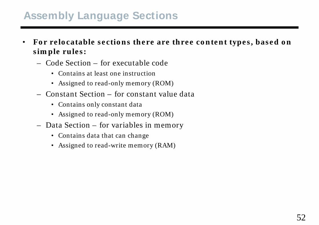
• For relocatable sections there are three content types, based on i l lsimple rules:– Code Section – for executable code
• Contains at least one instructionContains at least one instruction• Assigned to read-only memory (ROM)
– Constant Section – for constant value data• Contains only constant data• Assigned to read-only memory (ROM)
Data Section for variables in memory– Data Section – for variables in memory• Contains data that can change• Assigned to read-write memory (RAM)
52
Relocatable Program
• In hand assembling the file, we are taking on the job of the bl d th li k t thassembler and the linker, together
• The assembler does not know:– Where any sections actually go into memory– Where any sections actually go into memory– Where the stack will be in memory
• The linker has some work to do:– Place each section into memory– Build the vector table which includes the reset address but was not
shown above
53
Significant Topics
• CPU registers• Memory map• Instruction format
Addressing modes effective address (EA)• Addressing modes, effective address (EA)• Instruction encoding• Assembler syntax directives symbols labels• Assembler syntax, directives, symbols, labels• Absolute assembler• Relocatable assembler, sections, parameter file, , p• Hand assembly• Machine code in memory, dump file• Execution history
54
O G COSPORTING UCOS-II
55
Porting microC/OS-II
• Goal: Adapting a kernel to a microprocessori• Processor Requirement to Run uC/OS-II
– to have a C compiler generating reentrant codesto support interrupts at the speed of 10 to 100 H– to support interrupts at the speed of 10 to 100 Hz
– interrupts can be enabled and disabled from C– to support a hardware stackto support a hardware stack– to support instructions to load and store the stack point and registers
56
uC/OS-II Software Architecture
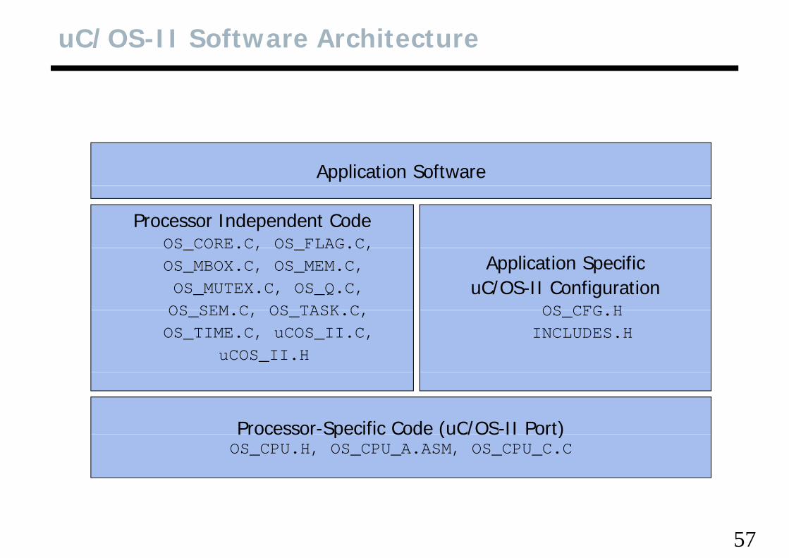
Application Software
Processor Independent CodeOS CORE.C, OS FLAG.C,OS_CORE.C, OS_FLAG.C,OS_MBOX.C, OS_MEM.C, OS_MUTEX.C, OS_Q.C,OS SEM C OS TASK C
Application SpecificuC/OS-II Configuration
OS CFG HOS_SEM.C, OS_TASK.C,OS_TIME.C, uCOS_II.C,
uCOS_II.H
OS_CFG.HINCLUDES.H
Processor-Specific Code (uC/OS-II Port)Processor Specific Code (uC/OS II Port)OS_CPU.H, OS_CPU_A.ASM, OS_CPU_C.C
57
Minimal Program
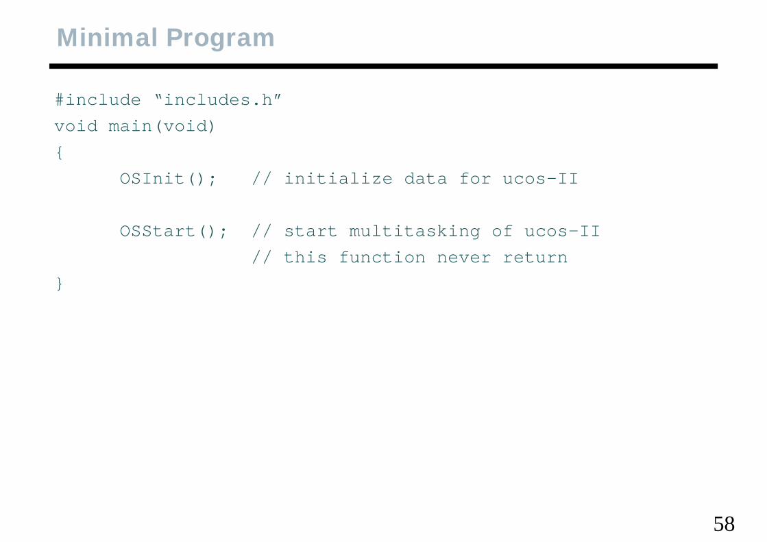
#include “includes.h”id i ( id)void main(void)
{OSInit(); // initialize data for ucos-IIOSInit(); // initialize data for ucos II
OSStart(); // start multitasking of ucos-II// this function never return
}
58
INCLUDES.H
• meta-include filei l d h fil i fil• include the file in every C files
• so you need not worry about which header filemay be discarded for effective compilation• may be discarded for effective compilation
59
OS_CFG.H
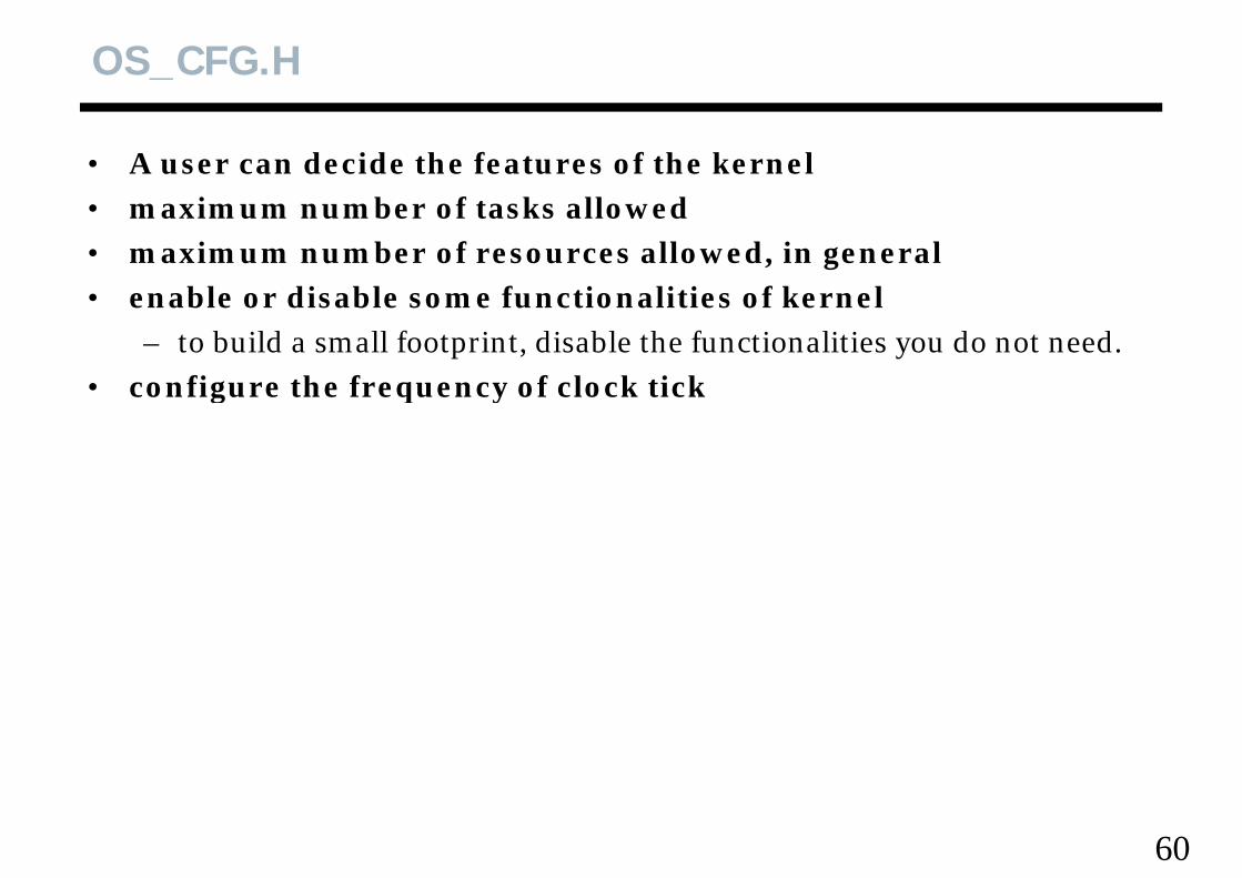
• A user can decide the features of the kerneli b f k ll d• maximum number of tasks allowed
• maximum number of resources allowed, in generalenable or disable some functionalities of kernel• enable or disable some functionalities of kernel– to build a small footprint, disable the functionalities you do not need.
• configure the frequency of clock tick • configure the frequency of clock tick
60
OS_CPU.H
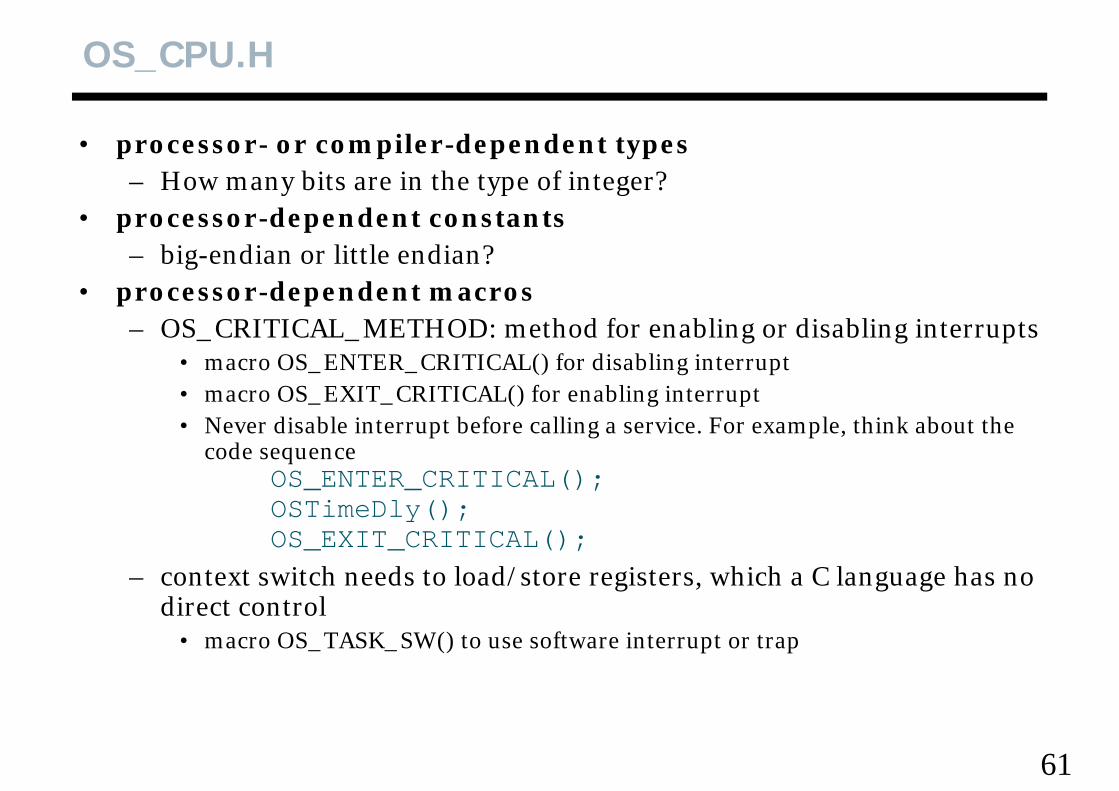
• processor- or compiler-dependent typesH bit i th t f i t ?– How many bits are in the type of integer?
• processor-dependent constants– big-endian or little endian?big endian or little endian?
• processor-dependent macros– OS_CRITICAL_METHOD: method for enabling or disabling interrupts
• macro OS_ENTER_CRITICAL() for disabling interrupt• macro OS_EXIT_CRITICAL() for enabling interrupt• Never disable interrupt before calling a service. For example, think about the
code sequenceOS_ENTER_CRITICAL();OSTimeDly();OS_EXIT_CRITICAL();
– context switch needs to load/store registers, which a C language has no direct controldirect control
• macro OS_TASK_SW() to use software interrupt or trap
61
OS_CPU_C.C
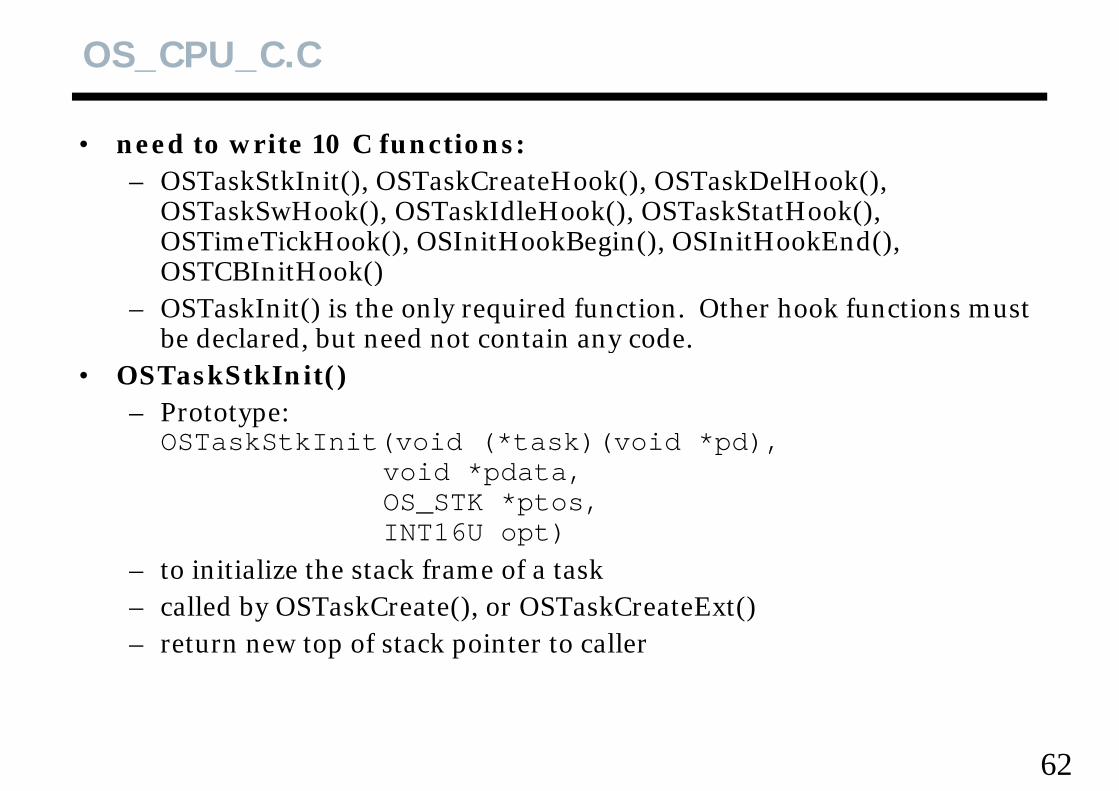
• need to write 10 C functions: OST kStkI it() OST kC t H k() OST kD lH k() – OSTaskStkInit(), OSTaskCreateHook(), OSTaskDelHook(), OSTaskSwHook(), OSTaskIdleHook(), OSTaskStatHook(), OSTimeTickHook(), OSInitHookBegin(), OSInitHookEnd(), OSTCBI itH k()OSTCBInitHook()
– OSTaskInit() is the only required function. Other hook functions must be declared, but need not contain any code., y
• OSTaskStkInit()– Prototype:OSTaskStkInit(void (*task)(void *pd)OSTaskStkInit(void (*task)(void *pd),
void *pdata, OS_STK *ptos, INT16U t)INT16U opt)
– to initialize the stack frame of a task– called by OSTaskCreate(), or OSTaskCreateExt()called by OSTaskCreate(), or OSTaskCreateExt()– return new top of stack pointer to caller
62
OS_CPU_C.C, Hook Functions
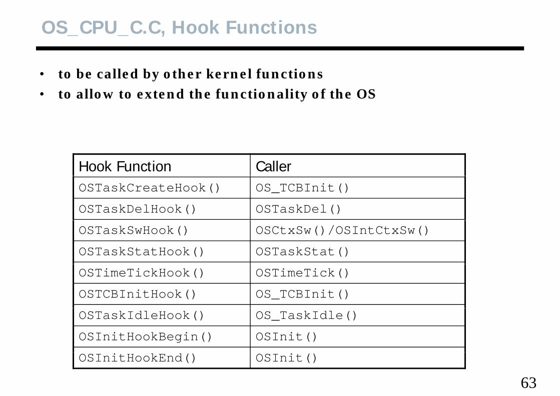
• to be called by other kernel functionsll d h f i li f h• to allow to extend the functionality of the OS
Hook Function CallerOSTaskCreateHook() OS_TCBInit()
OSTaskDelHook() OSTaskDel()
OSTaskSwHook() OSCtxSw()/OSIntCtxSw()
OSTaskStatHook() OSTaskStat()
OSTimeTickHook() OSTimeTick()
OSTCBInitHook() OS_TCBInit()
OSTaskIdleHook() OS_TaskIdle()
OSInitHookBegin() OSInit()
63
OSInitHookEnd() OSInit()
OS_CPU_A.ASM
• need to write 4 functions in assembly languageh d k– OSStartHighRdy(), OSCtxSw(), OSInitCtxSw(), OSTickISR()
• If C compiler supports in-line assembly, they can be written in OS CPU C COS_CPU_C.C
• They must be in assembly, because they directly handle CPU registers.
64
OS_CPU_A.ASM, OSStartHighRdy()
• to be called by OSStart() to start the highest priority task readyd d• Pseudo-code
call OSTaskSwHook()OSRunning = TRUEOSRunning = TRUEGet the stack pointer of task to resume by doing
Stack point = OSTCBHighRdy->OSTCBSTKPtrrestore all CPU registers from new task’s stackexecute a return from interrupt instruction
f lli () l k b d• Before calling OSStart(), at least one task must be created !!!
65
OS_CPU_A.ASM, OSCtxSw()
• task-level context switchd d• Pseudo-code
Save CPU registersSa e the stack pointer of the current task into its OS TCB bSave the stack pointer of the current task into its OS_TCB by
OSTCBCur->OSTCBStkPtr = Stack pointer
OSTaskSwHook()OSTaskSwHook()OSTCBCur = OSTCBHighRdyOSPrioCur = OSPrioHighRdyGet the stack pointer of the task to resume by
stack point = OSTCBHighRdy->OSTCBStkPtr
C i f h k’ kRestore CPU register from the new task’s stackExecute a return from interrupt instruction
66
OS_CPU_A.ASM, OSTickISR()
• must provide a periodic time sourcef d t H• preferred 10 to 100 Hz
• must enable ticker interrupts after multitasking starts (ie. after calling OSStart())g ())
– How can we do this? OSStart() never return!!!!! – Before calling OSStart(), create a task that initialize the timer.
d d• Pseudo-codesave CPU registerscall OSIntEnter()call OSIntEnter()if (OSIntNesting == 1) {
OSTCBCur->OSTCBStkPtr = stack pointer}}clear interrupting deviceOSTimeTick();();OSIntExit();restore CPU registers
f i i i
67
execute a return from interrupt instruction
OS_CPU_A.ASM, OSIntCtxSw()
• to perform a context switch from an ISRd i d h i d k• so assumed CPU registers are saved on the interrupted task’s
stack• Pseudo-code• Pseudo-code
call OSTaskSwHook()OSTCBCur = OSTCBHighRdyg yOSPrioCur = OSPrioHighRdyget the stack pointer of the task to resume by doing
stack pointer = OSTCBHighRdy->OSTCBStkPtr
Restore CPU registers from the new task’s stackexecute a return from interrupt instructionexecute a return from interrupt instruction
68
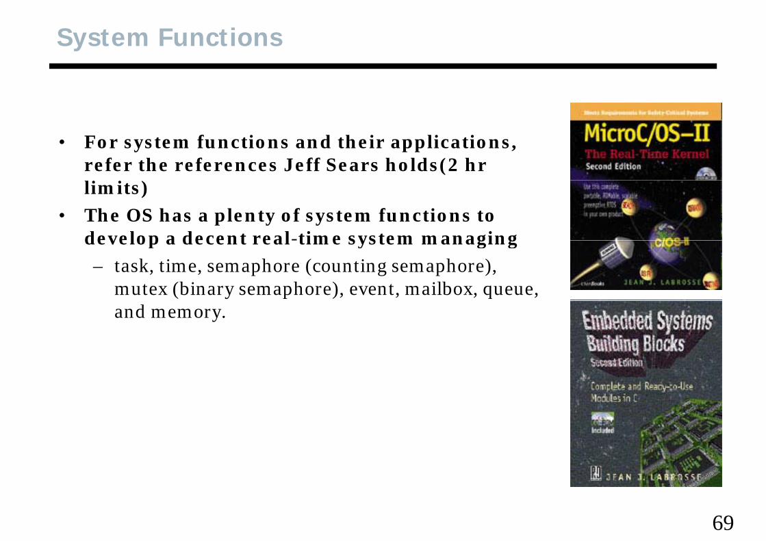
System Functions
• For system functions and their applications, refer the references Jeff Sears holds(2 hr li i )limits)
• The OS has a plenty of system functions to develop a decent real-time system managing develop a decent real time system managing – task, time, semaphore (counting semaphore),
mutex (binary semaphore), event, mailbox, queue, and memory.
69
Watchdog Timers
• A real-time system can fail due toh d bl– hardware problems
– software problemsunanticipated situations– unanticipated situations
• Continuous operation of most real-time systems is very critical• How to recover the system from failures (fault-tolerance)• How to recover the system from failures (fault-tolerance)• The Simple Technology, Reboot• Real-time systems are usually unattendedy y
– a user does not know their failures– Let them reboot by themselves
70
Watchdog Timer, Operation of
• hardware down-counter at a fixed intervalIf th t h th t hd h d d • If the counter reaches zero, the watchdog hardware sends a RESET signal to CPU
– the system is rebootedy• Software has to set the value of watchdog timer so that it
never reaches zero, periodicallyid d ()void wd_manager()
{while (1) {
restart_watchdog_counter(mcnt);OSTimeDly(time_wd_timer);
}}}
• Will this code work? – What priority will you give to the code?– What if other tasks make the problem?
71
Watchdog Timer in Multitask Systems
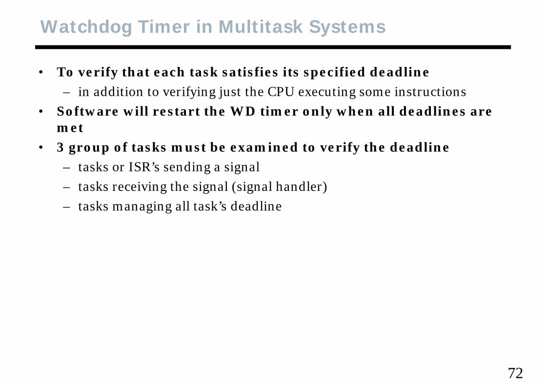
• To verify that each task satisfies its specified deadlinedd f h– in addition to verifying just the CPU executing some instructions
• Software will restart the WD timer only when all deadlines are metmet
• 3 group of tasks must be examined to verify the deadline– tasks or ISR’s sending a signalg g– tasks receiving the signal (signal handler) – tasks managing all task’s deadline
72
Example
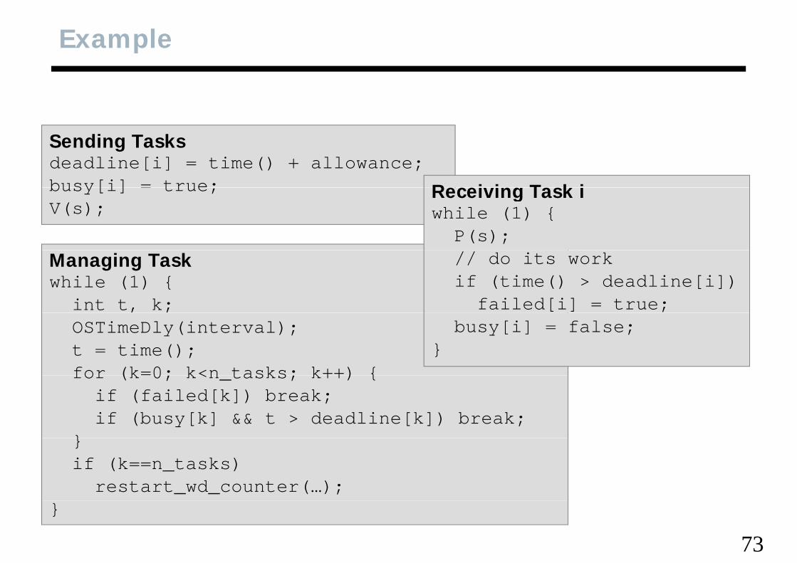
Sending Tasksdeadline[i] = time() + allowance;busy[i] = true; Receiving Task ibusy[i] true;V(s);
Receiving Task iwhile (1) {
P(s);Managing Taskwhile (1) {
int t, k;
// do its workif (time() > deadline[i])
failed[i] = true;OSTimeDly(interval);t = time();for (k=0; k<n tasks; k++) {
busy[i] = false;}
for (k 0; k<n_tasks; k++) {if (failed[k]) break;if (busy[k] && t > deadline[k]) break;
}}if (k==n_tasks)
restart_wd_counter(…);
73}
WD Manager
• Simple and fast to compute the checkpointsi f l• Execute infrequently
– It is enough to run before the WD timer reach zeroGive a high priority to the WD manager• Give a high-priority to the WD manager
74
HC12 & S12 Watchdog Timer
• HC12(S12) Resets– Power-on reset– External reset
Computer Operating Properl (COP) reset– Computer Operating Properly (COP) reset• to detect software execution malfunctions• normally disabledy
– Clock monitor reset
75
COP Reset Registers
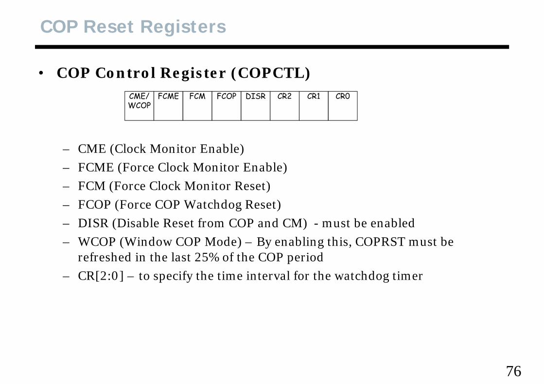
• COP Control Register (COPCTL)CME/WCOP
FCME FCM FCOP DISR CR2 CR1 CR0
– CME (Clock Monitor Enable)– FCME (Force Clock Monitor Enable)FCME (Force Clock Monitor Enable)– FCM (Force Clock Monitor Reset)– FCOP (Force COP Watchdog Reset)– DISR (Disable Reset from COP and CM) - must be enabled– WCOP (Window COP Mode) – By enabling this, COPRST must be
refreshed in the last 25% of the COP periodrefreshed in the last 25% of the COP period– CR[2:0] – to specify the time interval for the watchdog timer
76
COP Reset Registers, con’t
• Arm/Reset COP Timer Register (COPRST for HC12, ARMCOP for S12)S12)– COPRST (ARMCOP) must be reset by alternating $55 and $AA, The
alternating interval must be shorter than the timeout interval specified alternating interval must be shorter than the timeout interval specified by CR[2:0]
77
68 C 2 SS G68HC12 ADDRESSING
78
The CALL and RTC instructions in the CPU12 work with logic in the MCU t ll t th 4 b t fMCU to allow access to more than 4 megabytes of program memory. This is a compromise between linear addressing and bank switching. Linear addressing is easiest for programming but it makes mostLinear addressing is easiest for programming but it makes most instructions longer and slower (to allow the larger address to be specified in instructions). Linear addressing also places a cost penalty p ) g p p yon users that do not need more than 64k bytes of system memory. Bank switching schemes are normally difficult to manage because of three
i i i i i imain problems. First, the interrupt vectors must either reside in an unpaged memory space or they must be repeated in all banks. Second, interrrupts must be blocked during page switching to avoidinterrrupts must be blocked during page switching to avoid unpredictable results in the event an interrupt occured part way through the switching operation (this also adds program space and g g p ( p g pexecution time to perform the extra interrupt blocking and un-blocking). And third, the code that performed the bank switch had to
79reside in an unpaged portion of memory to avoid modification of the executing program (again this could add overhead to jump to the switching routine)
The CPU12 has a bank switching system but the CALL and RTC instructions eliminate the problems usually associated with suchinstructions eliminate the problems usually associated with such schemes. To fix the first problem, MCUs based on the CPU12 fix the paged block to be the 16k byte area from $8000 through $BFFF. Interrupt vectors are not located in this area and on-chip resourcesInterrupt vectors are not located in this area and on chip resources such as RAM, registers, and EEPROM can also avoid this area. An 8-bit register in the on-chip register space holds the bank select number (which specifies address output lines A14 through A22 for accesses to(which specifies address output lines A14 through A22 for accesses to extended program memory). The CPU12 uses dedicated control signals to access this PPAGE register so the CPU does not need toknow what the actual address of this register is The CALL instructionknow what the actual address of this register is. The CALL instruction works like a JSR except that the old PPAGE register value is stacked along with the return address and a new instruction-supplied value is
itt t PPAGE Si ll thi h ithi i t ti thwritten to PPAGE. Since all this happens within an instruction, there is no longer any need to block interrupts and the CALL and thedestination can reside anywhere including within different pages of
d d Th RTC i i k lik JSR hextended memory. The RTC instruction works like JSR except that the old PPAGE value is also restored from a value on the stack. For more info see the third article in this series.
80


![[PPT]Overview of MicroC/OS-II - Extra zenderpakketten bij ...home.kpn.nl/pj.fondse/overview_of_ucosii.ppt · Web viewTitle Overview of MicroC/OS-II Subject uC/OS-II Author Peter J](https://img.pdfslide.us/doc/110x75/5abef05a7f8b9a7e418d88db/pptoverview-of-microcos-ii-extra-zenderpakketten-bij-homekpnnlpjfondseoverviewof.jpg)


![RTSys Lecture Note - ch04 Clock-Driven Scheduling [호환 모드]et.engr.iupui.edu/~dskim/Classes/ESW5004/RTSys Lecture... · 2011. 7. 6. · Lecture Outline •Assumptions and notation](https://img.pdfslide.us/doc/110x75/61069439c503466f17560c1b/rtsys-lecture-note-ch04-clock-driven-scheduling-eeoeetengriupuiedudskimclassesesw5004rtsys.jpg)