Embed Size (px)
Citation preview
AN1255Microchip ZigBee® PRO Feature Set Protocol Stack
INTRODUCTIONThe ZigBee® protocol is a wireless network protocoldeveloped specifically for low data rate sensor andcontrol networks. Wireless applications that may bene-fit from ZigBee include, but are not limited to, industrialcontrols, home and building automation, PC peripher-als, medical sensor applications and security networks.
The latest protocol specifications ratified by the ZigBeeAlliance is collectively referred to as ZigBee-2007.ZigBee-2007 defines two distinct levels of functionalityor feature sets. The standard set is called ZigBee, andthe more advanced feature set is named ZigBee PRO.When compared against ZigBee, the ZigBee PRO fea-ture set offers many enhanced networking capabilities,and, under certain conditions, is backwards compatiblewith ZigBee.
The purpose of this application note is to provide adescription of the ZigBee PRO Features Set as imple-mented by the Microchip ZigBee PRO Stack. Thesefeatures are described in the “ZigBee Pro Feature SetOverview” section of this document.
ASSUMPTIONThis application note is not self contained, and does notprovide an introduction to the ZigBee protocol. Rather,it builds upon the information provided in a previousapplication note AN1232, “Microchip ZigBee-2006Residential Stack Protocol”. For readers who are notfamiliar with Zigbee or previous releases of Microchip’sZigBee Stack, it is highly advised that application noteAN1232 be carefully reviewed prior to reading this doc-ument or attempting to use the ZigBee PRO FeatureSet Stack. Many introductory concepts related to theZigBee protocol and how the Microchip ZigBee Stacksare structured are covered in that application note andare therefore not repeated here.
Furthermore, this document assumes that the reader isfamiliar with the ZigBee protocol and its terminology.The reader is also expected to be familiar with the Cprogramming language, as well as the IEEE 802.15.4-2003 specifications in detail. For additional technicalinformation on the IEEE 802.15.4™ specifications,please refer to http://standards.ieee.org/catalog/. Foradditional technical information on the ZigBeespecifications, please refer to www.zigbee.org.
DISTRIBUTION NOTICECompanies wishing to distribute a product that uses theMicrochip ZigBee PRO Stack for the wireless networkprotocol portion of their product must be members of theZigBee Alliance. Additionally, companies may only usethe Microchip ZigBee PRO Stack in their products whenit is used in conjunction with a Microchip transceiver andmicrocontroller. Please refer the software license thataccompanies the stack. For additional informationregarding Zigbee licenses and product certification, referto www.zigbee.org and specifically to document“053594r03_ZQG_ZigBee_Certification”.
ZigBee COMPLIANT PLATFORMThe Microchip ZigBee PRO Protocol Stack has beencertified as a ZigBee Compliant Platform (ZCP)consisting of the following modules:
• Processor: PIC24F and dsPIC33 families of microcontrollers
• Transceiver: MRF24J40• Firmware: Version 2.0.PRO.2.0 of the Microchip
ZigBee PRO Stack
FEATURESThe Microchip ZigBee PRO Stack is designed to evolvewith the ZigBee wireless protocol specifications. At thetime of this publication, the current applicable ZigBeespecification document is 05347 r17. This documentapplies to Microchip’s ZigBee PRO Stack releasesv2.0.PRO.2.0 and greater. The Microchip ZigBee-2006Stack is described in application note AN1232.
The Microchip ZigBee PRO Stack offers the followingfeatures:
• A certified ZigBee PRO Compliant Platform (ZCP)• Support for the 2.4 GHz frequency band using the
MRF24J40 transceiver• Support for all ZigBee protocol device types
(Coordinator, Routers and Reduced Function End Devices)
• Stochastic Address and Address Conflict Resolution mechanisms are supported
Author: Derrick P. LattibeaudiereMicrochip Technology Inc.
Note: The Microchip ZigBee PRO Stack is avail-able for purchase from the www.micro-chipdirect.com website. Due togovernmental security regulations regard-ing 128-bit encryption software, theZigBee PRO stack is not available fordownload from the Microchip website.
© 2009 Microchip Technology Inc. DS01255A-page 1
AN1255
• Support for Data Fragmentation and Reassembly• Support for Frequency Agility and DynamicChannel Selection• Support for Source Routing• Support for Many-to-One Routing• PANID Conflict Detection and Resolution
Mechanism is supported• Support for High Security Key Exchange• Support for Centralized Data Collection (ZigBee
Concentrator Device)• Support for Commissioning via the Startup
Attribute Set (SAS)• RTOS and application independent• Portable across the PIC24 MCU and dsPIC33
DSC families• Out-of-box support for Microchip MPLAB® C
Compiler for PIC24 MCUs and dsPIC DSCs• Implements nonvolatile storage for critical network
parameters such as Neighbor and Routing Tables
CONSIDERATIONSVersion 2.0.PRO.2.0 of the Microchip Stack for the Zig-Bee Protocol is the third version to be granted the sta-tus of ZigBee Compliant Platform (ZCP).
For information on the ZCP status of version v2.0-2.6,please refer to AN1232, “Microchip ZigBee-2006Residential Stack Protocol”.
The first version, v1.0-3.8, of the Microchip’s ZigBeeStack has been deprecated and is no longer supported.Users are encouraged to migrate to either version v2.0-2.6 or to the ZigBee PRO version 2.0-PRO.2.0 that isdescribed in this document.
LIMITATIONSThe ZigBee protocol specifications leave many higherlevel decisions up to the developer and productdesigner. As such, the Microchip ZigBee PRO Stackprovides no explicit support for the following functionsin the current release:
• Beacon networks are not supported in this version of the ZigBee PRO protocol stack.
• The Smart Energy Profile is not implemented• The Home Automation Profile is not implemented• The SKKE security mechanism is not
implemented• The ZigBee Cluster Library (ZCL) is not
implemented• Alternate PAN coordinator capability is not sup-
ported in ZigBee protocol networks. Only a single ZigBee protocol coordinator is permitted.
• The Zena™ Packet Sniffer does not currently sup-port this released version of the ZigBee PRO Feature Set Stack. Microchip recommends using Daintree Sensor Network Analyzer (SNA) for customers’ ZigBee PRO developments.
DEVELOPMENT TOOLS REQUIREMENTSIn order to use the Microchip ZigBee PRO Stack to cre-ate a ZigBee protocol network consisting of ZigBeedevices, the following development tools are required.
The hardware platform consists the following (one eachper network node):
• Explorer 16 (DM240001) board• PIC24FJ128GA010 Plug-In-Module (PIM)
(MA240011) • MRF24J40 2.4 GHz Daughter Card (AC163027-
4) or MRF24J40MA PICtail™ Plus 2.4G Hz RF Card (AC164134)
Miscellaneous Hardware
• At least one RS-232 Serial Cable in order to configure and communicate with the hardware
• Personal Computer with RS-232 COM port or USB to RS-232 adapter
• A programmer such as MPLAB REAL ICE™ in-circuit emulator or MPLAB ICD 3
Software Tools
• MPLAB C Compiler for PIC24 MCUs and dsPIC DSCs
• MPLAB IDE v8.10 or later• The source code for Microchip ZigBee PRO Stack
version v2.0.PRO.2.0 or higher• Daintree Sensor Network Analyzer (SNA) or simi-
lar ZigBee Packet Sniffer for those intending to do moderate to complex application development with this stack (optional)
Together these development tools will allow the user tocreate a ZigBee network using the Microchip ZigBeePRO Stack. The exact procedure of how to do this iscovered in the ZigBeePROQuickStartGuide.chmdocument that accompanies the stack software.
DS01255A-page 2 © 2009 Microchip Technology Inc.

AN1255
ZigBee PRO FEATURE SET OVERVIEWThe following sections provide an in-depth discussionof the important features that make up the ZigBee PROFeature Set. Where appropriate, specifics of how eachfeature is implemented and its impact on the futuredevelopment of other ZigBee profiles is also covered.
Stochastic AddressingThe Stochastic Addressing feature of the ZigBee PROStack allows each device that joins the network to berandomly assigned a unique 16-bit network address.The only exception is the ZigBee Coordinator, whichstill retains a network address of 0x0000.
This random network address assignment stands incontrast to the CSKIP mechanism employed in the Zig-Bee-2006 Stack, where network addresses were pre-determined and distributed based on device type andthe network topology.
Under the stochastic addressing scheme, once adevice has been assigned its network address, it maychoose not to relinquish it, unless that address comesin conflict with another device on the network. This istrue even during the rejoin process, when a device maybe switching parents.
The Stochastic addressing mechanism in ZigBee PROsimplifies the network address calculation (the CSKIPalgorithm vs. generating a random number), andremoves the linkage between the network address ofan individual device and its position within the networktopology. One benefit of this feature is that the entireaddressing space is now made available to eachpotential parent device on the network.
Figure 1 shows a sample ZigBee PRO network consist-ing of four devices, and their associated randomly gen-erated network addresses. Note the difference in thenetwork address assignment when compared againstthe ZigBee-2006 Stack.
Version 2.0-2.6 of the Microchip ZigBee-2006 Stackdoes not support the stochastic addressing feature.
FIGURE 1: STOCHASTIC NETWORK ADDRESSES OF ZigBee® PRO DEVICES
Microchip
Microchip
© 2009 Microchip Technology Inc. DS01255A-page 3

AN1255
Address Conflict Detection and ResolutionAn address conflict occurs when two devices on thesame network have identical network addresses. Moreprecisely, an address conflict arises when the samenetwork address gets associated with two differentMAC addresses. This conflict situation can arise, forexample, when two parent devices generate the samerandom network address for each of their respectivechild devices, where both child devices have differentMAC addresses.The detection of an address conflict usually occurswhen a device that has just joined the network broad-casts an announcement to notify the other devices thatit is now a member of the network. This announcementis called a ZigBee EndDeviceAnnce message andcarried within its payload are both the MAC and net-work address of the newly joined device, as well as abyte that identifies the capabilities of the device. Anexample of the information contained in the Capabilitybyte would be that the device is an RFD, its transmitteris turned off when the device is idle, and it does notsupport security.
Figure 2 shows a packet sniffer capture of theEndDeviceAnnce message that is broadcasted to alldevices in the network.
FIGURE 2: PACKET SNIFFER CAPTURE OF AN EndDeviceAnnce MESSAGE
After every device announcement is received, routersand the Coordinator will compare the new device’s net-work address against all the known addresses in theiraddress map and neighbor tables. If another devicewith the same network address as the newly joineddevice is found, or the new network address is thesame as the router’s own, then a status command isbroadcasted throughout the network indicating anaddress conflict situation has been detected.
If the device with the address conflict is a ReducedFunction End Device, the parent of that device willchoose a new random network address for the child. Itwill then send an unsolicited rejoin command to thechild, forcing it to accept the new network address, thusalleviating the address conflict. This new networkaddress is embedded in the payload of the unsolicitedrejoin command.
If a router is the device that is the source of the addressconflict, it will assign a new address to itself andannounce its new address via a new EndDeviceAnncemessage.
Figure 3 shows an example of the sniffer capture of theaddress conflict detection and resolution mechanism atwork.
DS01255A-page 4 © 2009 Microchip Technology Inc.
AN1255
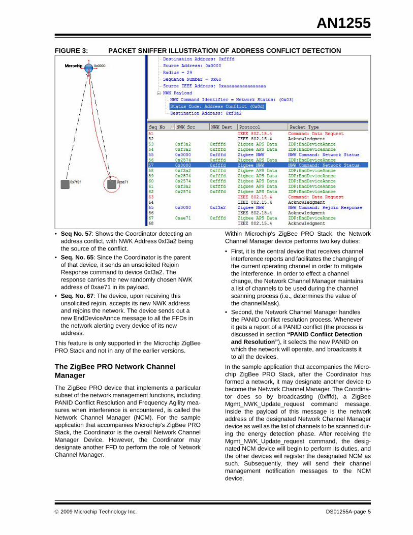
FIGURE 3: PACKET SNIFFER ILLUSTRATION OF ADDRESS CONFLICT DETECTION• Seq No. 57: Shows the Coordinator detecting an address conflict, with NWK Address 0xf3a2 being the source of the conflict.
• Seq. No. 65: Since the Coordinator is the parent of that device, it sends an unsolicited Rejoin Response command to device 0xf3a2. The response carries the new randomly chosen NWK address of 0xae71 in its payload.
• Seq. No. 67: The device, upon receiving this unsolicited rejoin, accepts its new NWK address and rejoins the network. The device sends out a new EndDeviceAnnce message to all the FFDs in the network alerting every device of its new address.
This feature is only supported in the Microchip ZigBeePRO Stack and not in any of the earlier versions.
The ZigBee PRO Network Channel ManagerThe ZigBee PRO device that implements a particularsubset of the network management functions, includingPANID Conflict Resolution and Frequency Agility mea-sures when interference is encountered, is called theNetwork Channel Manager (NCM). For the sampleapplication that accompanies Microchip's ZigBee PROStack, the Coordinator is the overall Network ChannelManager Device. However, the Coordinator maydesignate another FFD to perform the role of NetworkChannel Manager.
Within Microchip's ZigBee PRO Stack, the NetworkChannel Manager device performs two key duties:
• First, it is the central device that receives channel interference reports and facilitates the changing of the current operating channel in order to mitigate the interference. In order to effect a channel change, the Network Channel Manager maintains a list of channels to be used during the channel scanning process (i.e., determines the value of the channelMask).
• Second, the Network Channel Manager handles the PANID conflict resolution process. Whenever it gets a report of a PANID conflict (the process is discussed in section “PANID Conflict Detection and Resolution”), it selects the new PANID on which the network will operate, and broadcasts it to all the devices.
In the sample application that accompanies the Micro-chip ZigBee PRO Stack, after the Coordinator hasformed a network, it may designate another device tobecome the Network Channel Manager. The Coordina-tor does so by broadcasting (0xfffd), a ZigBeeMgmt_NWK_Update_request command message.Inside the payload of this message is the networkaddress of the designated Network Channel Managerdevice as well as the list of channels to be scanned dur-ing the energy detection phase. After receiving theMgmt_NWK_Update_request command, the desig-nated NCM device will begin to perform its duties, andthe other devices will register the designated NCM assuch. Subsequently, they will send their channelmanagement notification messages to the NCMdevice.
© 2009 Microchip Technology Inc. DS01255A-page 5

AN1255
PANID Conflict Detection and ResolutionA PANID conflict occurs when any device operating ona ZigBee PRO network receives a beacon frame via aMLME-BEACON-NOTIFY, indication primitive, in whichthe PANID of the beacon frame matches that of its ownPAN Identifier, but the Extended PANID containedwithin the beacon frame's payload does not match itsown Extended PANID, at which point the device hasdetected a PANID conflict.
Any device that detects a PANID conflict will report it tothe current device that is designated as the NetworkChannel Manager via a ZigBee defined NetworkReport Pan Identifier Report Conflict command frame.
Upon receipt of the Network Report Pan IdentifierReport Conflict command frame, the Network Managercreates a new random 16-bit PANID, and transmits it tothe other devices via a Network Update PAN IdentifierUpdate command broadcast (destination address0xffff).
All the devices on the network, upon receipt of the PANIdentifier Update command, will extract the new PANIdentifier from the command payload, and update theirbeacon payloads accordingly.
From an implementation perspective, this new PANIDis also written in the transceiver hardware, effectivelyswitching the network to a new PAN for the purpose ofPAN filtering incoming packets.
Figure 4 and Figure 5 show packet sniffer traces of theof network commands that are transmitted during theprocess of detecting and resolving a PAN Identifierconflict on Microchip's ZigBee PRO network.
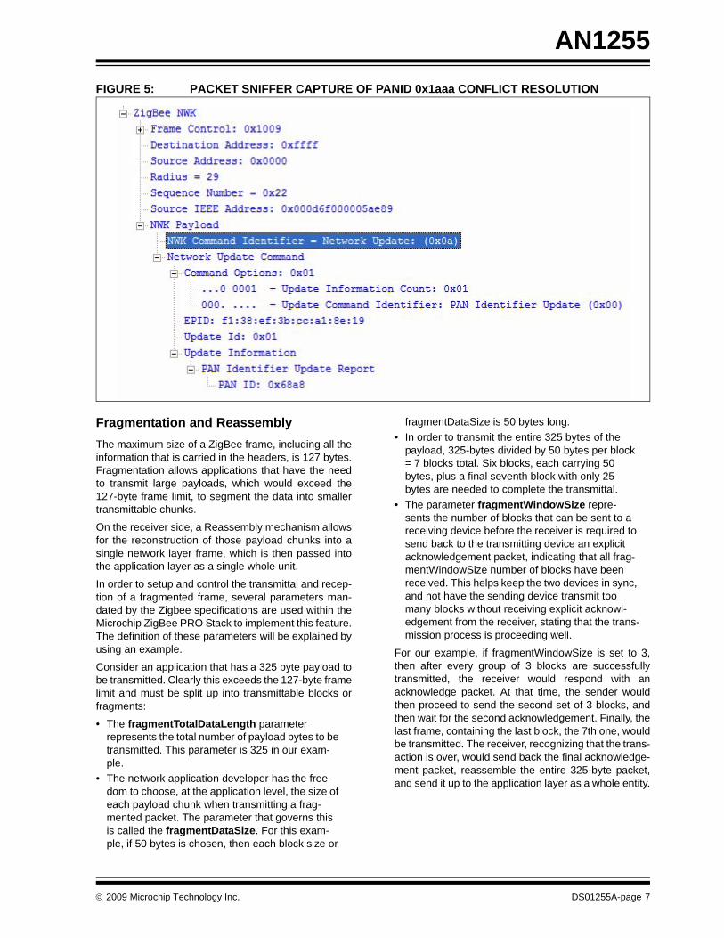
FIGURE 4: PACKET SNIFFER CAPTURE OF PANID 0x1aaa CONFLICT DETECTION
Note: A ZigBee PRO network has two PersonalArea Network Identifiers (PANID). The firstis a 64-bit globally unique PAN identifiernamed the Extended PANID, that shouldbe unique within any overlapping networkarea. The second is 16-bit PAN Identifiercalled the Short PANID. When usedtogether, this pair, the Extended and ShortPANIDs, shall uniquely identify the net-work.
DS01255A-page 6 © 2009 Microchip Technology Inc.
AN1255
FIGURE 5: PACKET SNIFFER CAPTURE OF PANID 0x1aaa CONFLICT RESOLUTIONFragmentation and ReassemblyThe maximum size of a ZigBee frame, including all theinformation that is carried in the headers, is 127 bytes.Fragmentation allows applications that have the needto transmit large payloads, which would exceed the127-byte frame limit, to segment the data into smallertransmittable chunks.
On the receiver side, a Reassembly mechanism allowsfor the reconstruction of those payload chunks into asingle network layer frame, which is then passed intothe application layer as a single whole unit.
In order to setup and control the transmittal and recep-tion of a fragmented frame, several parameters man-dated by the Zigbee specifications are used within theMicrochip ZigBee PRO Stack to implement this feature.The definition of these parameters will be explained byusing an example.
Consider an application that has a 325 byte payload tobe transmitted. Clearly this exceeds the 127-byte framelimit and must be split up into transmittable blocks orfragments:
• The fragmentTotalDataLength parameter represents the total number of payload bytes to be transmitted. This parameter is 325 in our exam-ple.
• The network application developer has the free-dom to choose, at the application level, the size of each payload chunk when transmitting a frag-mented packet. The parameter that governs this is called the fragmentDataSize. For this exam-ple, if 50 bytes is chosen, then each block size or
fragmentDataSize is 50 bytes long.• In order to transmit the entire 325 bytes of the
payload, 325-bytes divided by 50 bytes per block = 7 blocks total. Six blocks, each carrying 50 bytes, plus a final seventh block with only 25 bytes are needed to complete the transmittal.
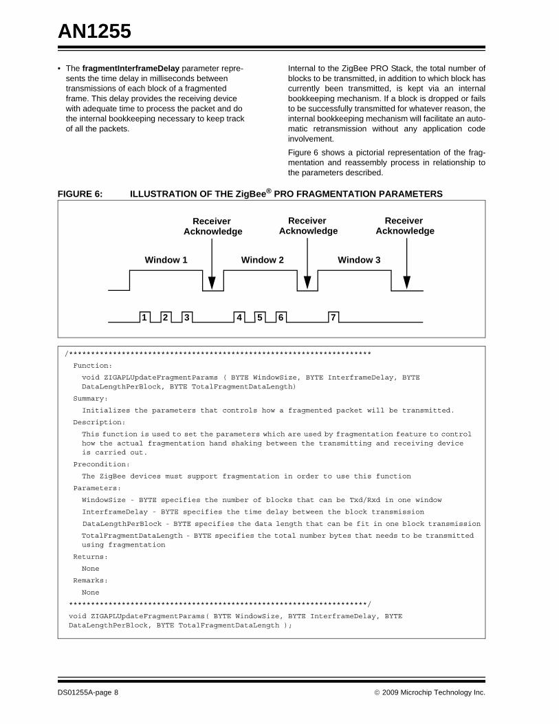
• The parameter fragmentWindowSize repre-sents the number of blocks that can be sent to a receiving device before the receiver is required to send back to the transmitting device an explicit acknowledgement packet, indicating that all frag-mentWindowSize number of blocks have been received. This helps keep the two devices in sync, and not have the sending device transmit too many blocks without receiving explicit acknowl-edgement from the receiver, stating that the trans-mission process is proceeding well.
For our example, if fragmentWindowSize is set to 3,then after every group of 3 blocks are successfullytransmitted, the receiver would respond with anacknowledge packet. At that time, the sender wouldthen proceed to send the second set of 3 blocks, andthen wait for the second acknowledgement. Finally, thelast frame, containing the last block, the 7th one, wouldbe transmitted. The receiver, recognizing that the trans-action is over, would send back the final acknowledge-ment packet, reassemble the entire 325-byte packet,and send it up to the application layer as a whole entity.
© 2009 Microchip Technology Inc. DS01255A-page 7
AN1255
• The fragmentInterframeDelay parameter repre-sents the time delay in milliseconds between transmissions of each block of a fragmented frame. This delay provides the receiving device with adequate time to process the packet and do the internal bookkeeping necessary to keep track of all the packets.
Internal to the ZigBee PRO Stack, the total number ofblocks to be transmitted, in addition to which block hascurrently been transmitted, is kept via an internalbookkeeping mechanism. If a block is dropped or failsto be successfully transmitted for whatever reason, theinternal bookkeeping mechanism will facilitate an auto-matic retransmission without any application codeinvolvement.
Figure 6 shows a pictorial representation of the frag-mentation and reassembly process in relationship tothe parameters described.
FIGURE 6: ILLUSTRATION OF THE ZigBee® PRO FRAGMENTATION PARAMETERS
Window 1 Window 2 Window 3
Receiver Acknowledge
Receiver Acknowledge
Receiver Acknowledge
1 2 3 4 5 6 7
/*********************************************************************
Function:
void ZIGAPLUpdateFragmentParams ( BYTE WindowSize, BYTE InterframeDelay, BYTE DataLengthPerBlock, BYTE TotalFragmentDataLength)
Summary:
Initializes the parameters that controls how a fragmented packet will be transmitted.
Description:
This function is used to set the parameters which are used by fragmentation feature to control how the actual fragmentation hand shaking between the transmitting and receiving device is carried out.
Precondition:
The ZigBee devices must support fragmentation in order to use this function
Parameters:
WindowSize - BYTE specifies the number of blocks that can be Txd/Rxd in one window
InterframeDelay - BYTE specifies the time delay between the block transmission
DataLengthPerBlock - BYTE specifies the data length that can be fit in one block transmission
TotalFragmentDataLength - BYTE specifies the total number bytes that needs to be transmitted using fragmentation
Returns:
None
Remarks:
None
********************************************************************/
void ZIGAPLUpdateFragmentParams( BYTE WindowSize, BYTE InterframeDelay, BYTE DataLengthPerBlock, BYTE TotalFragmentDataLength );
DS01255A-page 8 © 2009 Microchip Technology Inc.
AN1255
It is up to the application developer to set the defaultvalues for all the fragmentation/reassemble parame-ters that were discussed above, prior to calling theZIGAPLSendFragmentedPacket() function. For anexample of this, see the Sample demo application codethat is shipped with the Microchip ZigBee PRO Stacksample application.Frequency AgilityThe Frequency Agility feature gives a ZigBee PROapplication the ability to dynamically switch the currentchannel on which the network operates, primarily inresponse to detected “interference”.
In order to support this feature, a Network ChannelManager device is required. A ZigBee PRO NetworkChannel Manager is the device that is designated assuch in either the profile’s Node Descriptor, or dynami-cally by the Coordinator after the network has started.It has the responsibility of the managing the channelson which the ZigBee network operates.
Internally, the Microchip ZigBee PRO Stack keeps trackof the number of packets that are transmitted by eachtransceiver. By the standards set forth by the 802.15.4specifications, for each transmitted packet, there mustbe an associated MAC level acknowledgement. If noacknowledgement is received, then the packet isjudged to be lost and is counted as failure internally bythe stack. For a given channel, whenever the ratio ofthe total transmitted packets vs. the number of transmitfailures exceeds a 50% threshold, then the stackassumes there is some “interference” on that channeland this will automatically trigger the start of a correc-tive action.
The device that experiences a high level of transmitfailures will notify the Network Channel Manager bysending it a MGMT_NWK_UPDATE_NOTIFY com-mand. This command will indicate the total number ofattempted transmissions, the total failures, a list ofchannel scanned and their energy values. Thescanned channels and energy values provide usefulinformation that the Network Channel Manager makesuse of as it takes corrective action in order to avoid fur-ther interference.
The designer of the network application must decidewhat precise action to take in response to an interfer-ence MGMT_NWK_UPDATE_NOTIFY command.Here are a few possibilities:
• The Network Channel Manager, upon receipt of the MGMT_NWK_UPDATE_NOTIFY, may ask all devices to scan their channels, and use that infor-mation to decide which is the best channel for all the devices. Subsequently, it would tell all the devices to move to that new channel.
• The Network Channel Manager, upon receipts of the MGMT_NWK_UPDATE_NOTIFY, may use the information that is received from the single notifying device to decide which is the best chan-nel for all the devices. Subsequently it would tell all the devices to move to that new channel.
• The Network Channel Manager may decide to do nothing and continue to operate the network on the degraded channel.
The Network Channel Manager uses theMGMT_NWK_UPDATE_req command to broadcastthe channel change to all the devices in the network.After receiving this request, all the devices will switch tothe new channel and resume operation. The NetworkChannel Manager will also do the same.
It should be noted that the Microchip ZigBee PROStack provides the entire infrastructure to manage Fre-quency Agility, but it is up to the application designer tomake the final policy decision on how this feature actu-ally functions in their network. The sample applicationthat is provided with the Microchip ZigBee PRO Stackdemonstrates this feature.
Link Status CommandsThe coordinator and all routers operating on a ZigBeePRO network are required to periodically broadcast aLink Status Command. The Link Status Command car-ries a list of the device’s neighbors that are within aone-hop radio range.
Additionally, the link costs, both out-going and incom-ing, for each neighbor device are also included in theLink Status Command. The purpose of the Link StatusCommand is tri-fold:
First, the link status command is used to keep the num-ber of entries in the neighbor table as small as possible.Since each router must periodically broadcast a LinkStatus Command, each of its neighbors uses thereception of this command as an indication that thedevice that originated the command is alive andoperational.
If a router does not receive this command from a previ-ously neighboring device after a certain interval of time,then it removes that device from its neighbor table.Thus, if a device has moved outside the radio range, orhas become inactive, it will be no longer occupy a valu-able entry slot inside a neighboring device’s neighbortable.
Second, the Link Status Command is used to exchangethe link cost information with a devices' one-hop neigh-bors. The Link Status command carries within its pay-load the incoming and outgoing link cost of all its knownneighbors.
© 2009 Microchip Technology Inc. DS01255A-page 9
AN1255
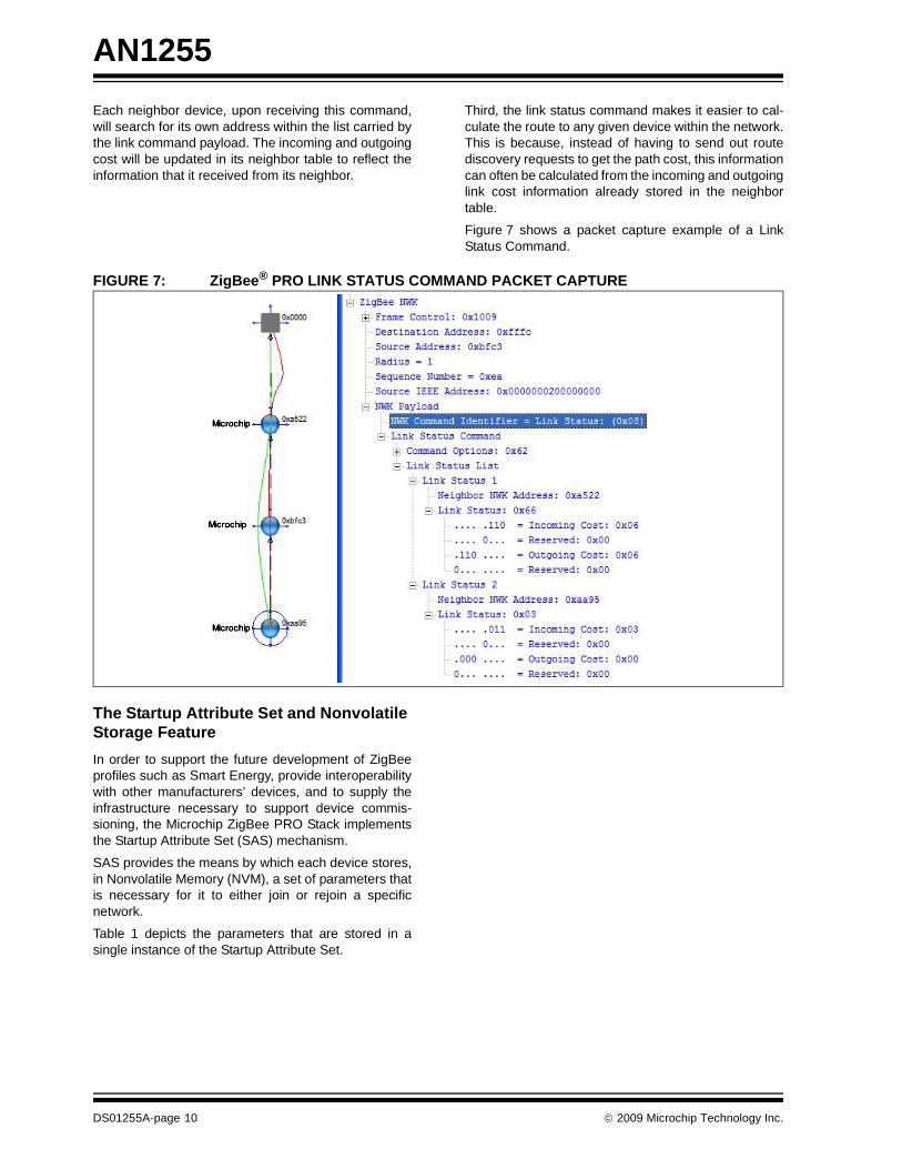
Each neighbor device, upon receiving this command,will search for its own address within the list carried bythe link command payload. The incoming and outgoingcost will be updated in its neighbor table to reflect theinformation that it received from its neighbor.Third, the link status command makes it easier to cal-culate the route to any given device within the network.This is because, instead of having to send out routediscovery requests to get the path cost, this informationcan often be calculated from the incoming and outgoinglink cost information already stored in the neighbortable.
Figure 7 shows a packet capture example of a LinkStatus Command.
FIGURE 7: ZigBee® PRO LINK STATUS COMMAND PACKET CAPTURE
The Startup Attribute Set and Nonvolatile Storage FeatureIn order to support the future development of ZigBeeprofiles such as Smart Energy, provide interoperabilitywith other manufacturers’ devices, and to supply theinfrastructure necessary to support device commis-sioning, the Microchip ZigBee PRO Stack implementsthe Startup Attribute Set (SAS) mechanism.
SAS provides the means by which each device stores,in Nonvolatile Memory (NVM), a set of parameters thatis necessary for it to either join or rejoin a specificnetwork.
Table 1 depicts the parameters that are stored in asingle instance of the Startup Attribute Set.
DS01255A-page 10 © 2009 Microchip Technology Inc.
AN1255
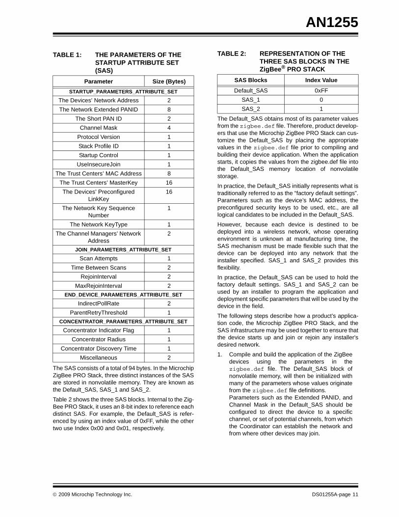
The SAS consists of a total of 94 bytes. In the MicrochipZigBee PRO Stack, three distinct instances of the SASare stored in nonvolatile memory. They are known asthe Default_SAS, SAS_1 and SAS_2.
Table 2 shows the three SAS blocks. Internal to the Zig-Bee PRO Stack, it uses an 8-bit index to reference eachdistinct SAS. For example, the Default_SAS is refer-enced by using an index value of 0xFF, while the othertwo use Index 0x00 and 0x01, respectively.
The Default_SAS obtains most of its parameter valuesfrom the zigbee.def file. Therefore, product develop-ers that use the Microchip ZigBee PRO Stack can cus-tomize the Default_SAS by placing the appropriatevalues in the zigbee.def file prior to compiling andbuilding their device application. When the applicationstarts, it copies the values from the zigbee.def file intothe Default_SAS memory location of nonvolatilestorage.
In practice, the Default_SAS initially represents what istraditionally referred to as the “factory default settings”.Parameters such as the device’s MAC address, thepreconfigured security keys to be used, etc., are alllogical candidates to be included in the Default_SAS.
However, because each device is destined to bedeployed into a wireless network, whose operatingenvironment is unknown at manufacturing time, theSAS mechanism must be made flexible such that thedevice can be deployed into any network that theinstaller specified. SAS_1 and SAS_2 provides thisflexibility.
In practice, the Default_SAS can be used to hold thefactory default settings. SAS_1 and SAS_2 can beused by an installer to program the application anddeployment specific parameters that will be used by thedevice in the field.
The following steps describe how a product’s applica-tion code, the Microchip ZigBee PRO Stack, and theSAS infrastructure may be used together to ensure thatthe device starts up and join or rejoin any installer'sdesired network.
1. Compile and build the application of the ZigBeedevices using the parameters in thezigbee.def file. The Default_SAS block ofnonvolatile memory, will then be initialized withmany of the parameters whose values originatefrom the zigbee.def file definitions. Parameters such as the Extended PANID, andChannel Mask in the Default_SAS should beconfigured to direct the device to a specificchannel, or set of potential channels, from whichthe Coordinator can establish the network andfrom where other devices may join.
TABLE 1: THE PARAMETERS OF THE STARTUP ATTRIBUTE SET (SAS)
Parameter Size (Bytes)STARTUP_PARAMETERS_ATTRIBUTE_SET
The Devices’ Network Address 2The Network Extended PANID 8
The Short PAN ID 2Channel Mask 4
Protocol Version 1Stack Profile ID 1Startup Control 1
UseInsecureJoin 1The Trust Centers’ MAC Address 8
The Trust Centers’ MasterKey 16The Devices’ Preconfigured
LinkKey16
The Network Key Sequence Number
1
The Network KeyType 1The Channel Managers’ Network
Address2
JOIN_PARAMETERS_ATTRIBUTE_SETScan Attempts 1
Time Between Scans 2RejoinInterval 2
MaxRejoinInterval 2END_DEVICE_PARAMETERS_ATTRIBUTE_SET
IndirectPollRate 2ParentRetryThreshold 1
CONCENTRATOR_PARAMETERS_ATTRIBUTE_SETConcentrator Indicator Flag 1
Concentrator Radius 1Concentrator Discovery Time 1
Miscellaneous 2
TABLE 2: REPRESENTATION OF THE THREE SAS BLOCKS IN THE ZigBee® PRO STACK
SAS Blocks Index Value
Default_SAS 0xFFSAS_1 0SAS_2 1
© 2009 Microchip Technology Inc. DS01255A-page 11
AN1255
2. After the Coordinator has established the net-work, the application code for each device canuse the appropriate API functions that aredescribed in this section to update the appropri-ate SAS_1 and SAS_2 block(s), to the parame-ters that will be used when the device isdeployed in their “permanent” network.
3. The devices, now with the deployable SAS_1and SAS_2 in nonvolatile memory, can berestarted using SAS_1 or SAS_2. This uses theDefault_SAS to get the devices configured, afterwhich the devices are restarted using eitherSAS_1 or SAS_2, while retaining the factorysettings in Default_SAS.
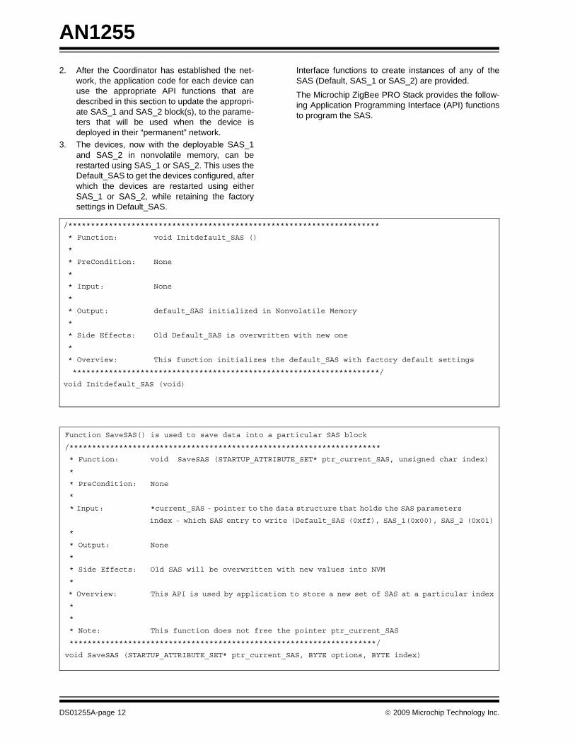
Interface functions to create instances of any of theSAS (Default, SAS_1 or SAS_2) are provided.
The Microchip ZigBee PRO Stack provides the follow-ing Application Programming Interface (API) functionsto program the SAS.
/*********************************************************************
* Function: void Initdefault_SAS ()
*
* PreCondition: None
*
* Input: None
*
* Output: default_SAS initialized in Nonvolatile Memory
*
* Side Effects: Old Default_SAS is overwritten with new one
*
* Overview: This function initializes the default_SAS with factory default settings
********************************************************************/
void Initdefault_SAS (void)
Function SaveSAS() is used to save data into a particular SAS block
/*********************************************************************
* Function: void SaveSAS (STARTUP_ATTRIBUTE_SET* ptr_current_SAS, unsigned char index)
*
* PreCondition: None
*
* Input: *current_SAS - pointer to the data structure that holds the SAS parameters
index - which SAS entry to write (Default_SAS (0xff), SAS_1(0x00), SAS_2 (0x01)
*
* Output: None
*
* Side Effects: Old SAS will be overwritten with new values into NVM
*
* Overview: This API is used by application to store a new set of SAS at a particular index
*
*
* Note: This function does not free the pointer ptr_current_SAS
********************************************************************/
void SaveSAS (STARTUP_ATTRIBUTE_SET* ptr_current_SAS, BYTE options, BYTE index)
DS01255A-page 12 © 2009 Microchip Technology Inc.
AN1255
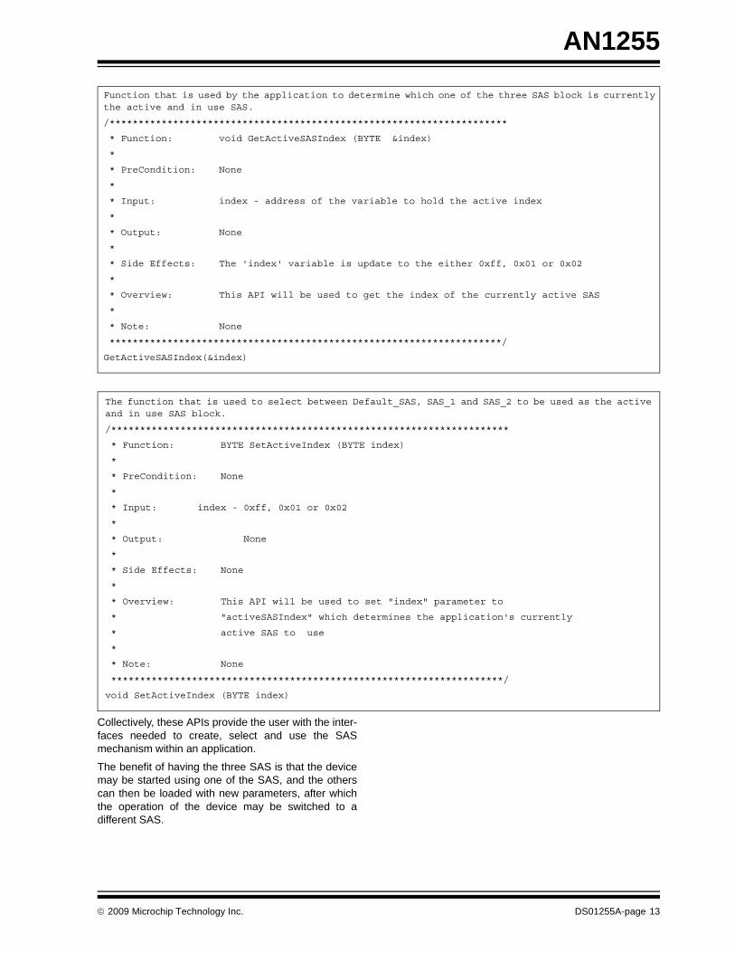
Collectively, these APIs provide the user with the inter-faces needed to create, select and use the SASmechanism within an application.
The benefit of having the three SAS is that the devicemay be started using one of the SAS, and the otherscan then be loaded with new parameters, after whichthe operation of the device may be switched to adifferent SAS.
The function that is used to select between Default_SAS, SAS_1 and SAS_2 to be used as the activeand in use SAS block.
/*********************************************************************
* Function: BYTE SetActiveIndex (BYTE index)
*
* PreCondition: None
*
* Input: index - 0xff, 0x01 or 0x02
*
* Output: None
*
* Side Effects: None
*
* Overview: This API will be used to set "index" parameter to
* "activeSASIndex" which determines the application's currently
* active SAS to use
*
* Note: None
********************************************************************/
void SetActiveIndex (BYTE index)
Function that is used by the application to determine which one of the three SAS block is currentlythe active and in use SAS.
/*********************************************************************
* Function: void GetActiveSASIndex (BYTE &index)
*
* PreCondition: None
*
* Input: index - address of the variable to hold the active index
*
* Output: None
*
* Side Effects: The 'index' variable is update to the either 0xff, 0x01 or 0x02
*
* Overview: This API will be used to get the index of the currently active SAS
*
* Note: None
********************************************************************/
GetActiveSASIndex(&index)
© 2009 Microchip Technology Inc. DS01255A-page 13
AN1255
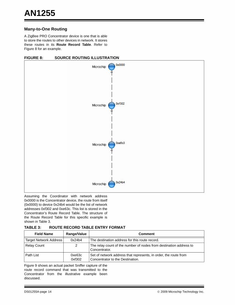
Many-to-One RoutingA ZigBee PRO Concentrator device is one that is ableto store the routes to other devices in network. It storesthese routes in its Route Record Table. Refer toFigure 8 for an example.FIGURE 8: SOURCE ROUTING ILLUSTRATION
Assuming the Coordinator with network address0x0000 is the Concentrator device, the route from itself(0x0000) to device 0x24b4 would be the list of networkaddresses 0xf302 and 0xe63c. This list is stored in theConcentrator’s Route Record Table. The structure ofthe Route Record Table for this specific example isshown in Table 3.
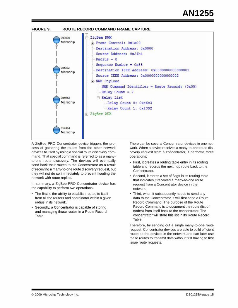
Figure 9 shows an actual packet Sniffer capture of theroute record command that was transmitted to theConcentrator from the illustrative example beendiscussed.
TABLE 3: ROUTE RECORD TABLE ENTRY FORMATField Name Range/Value Comment
Target Network Address 0x24b4 The destination address for this route record.Relay Count 2 The relay count of the number of nodes from destination address to
Concentrator.Path List 0xe63c
0xf302Set of network address that represents, in order, the route from Concentrator to the Destination.
DS01255A-page 14 © 2009 Microchip Technology Inc.
AN1255
FIGURE 9: ROUTE RECORD COMMAND FRAME CAPTUREA ZigBee PRO Concentrator device triggers the pro-cess of gathering the routes from the other networkdevices to itself by using a special route discovery com-mand. That special command is referred to as a many-to-one route discovery. The devices will eventuallysend back their routes to the Concentrator as a resultof receiving a many-to-one route discovery request, butthey will not do so immediately to prevent flooding thenetwork with route replies.
In summary, a ZigBee PRO Concentrator device hasthe capability to perform two operations:
• The first is the ability to establish routes to itself from all the routers and coordinator within a given radius in its network.
• Secondly, a Concentrator is capable of storing and managing those routes in a Route Record Table.
There can be several Concentrator devices in one net-work. When a device receives a many-to-one route dis-covery request from a concentrator, it performs threeoperations:
• First, it creates a routing table entry in its routing table and records the next hop route back to the Concentrator.
• Second, it stores a set of flags in its routing table that indicates it received a many-to-one route request from a Concentrator device in the network.
• Third, when it subsequently needs to send any data to the Concentrator, it will first send a Route Record Command. The purpose of the Route Record Command is to document the route (list of nodes) from itself back to the concentrator. The concentrator will store this list in its Route Record Table.
Therefore, by sending out a single many-to-one routerequest, Concentrator devices are able to build efficientroutes to the devices in the network and can later usethese routes to transmit data without first having to firstissue route requests.
© 2009 Microchip Technology Inc. DS01255A-page 15
AN1255
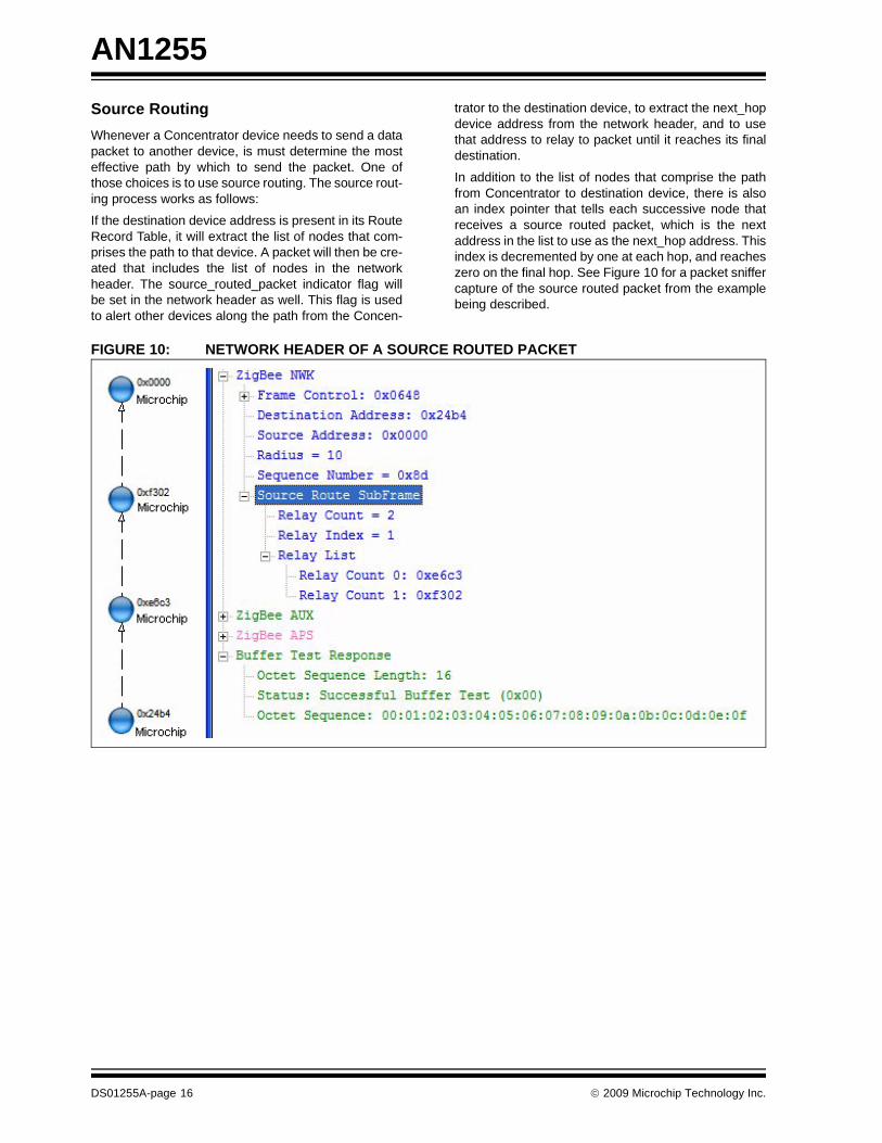
Source RoutingWhenever a Concentrator device needs to send a datapacket to another device, is must determine the mosteffective path by which to send the packet. One ofthose choices is to use source routing. The source rout-ing process works as follows:If the destination device address is present in its RouteRecord Table, it will extract the list of nodes that com-prises the path to that device. A packet will then be cre-ated that includes the list of nodes in the networkheader. The source_routed_packet indicator flag willbe set in the network header as well. This flag is usedto alert other devices along the path from the Concen-
trator to the destination device, to extract the next_hopdevice address from the network header, and to usethat address to relay to packet until it reaches its finaldestination.
In addition to the list of nodes that comprise the pathfrom Concentrator to destination device, there is alsoan index pointer that tells each successive node thatreceives a source routed packet, which is the nextaddress in the list to use as the next_hop address. Thisindex is decremented by one at each hop, and reacheszero on the final hop. See Figure 10 for a packet sniffercapture of the source routed packet from the examplebeing described.
FIGURE 10: NETWORK HEADER OF A SOURCE ROUTED PACKET
DS01255A-page 16 © 2009 Microchip Technology Inc.
AN1255
High Security Application Master Key ExchangeThe Microchip ZigBee PRO Feature Set Stack supportsthe high security mode of operation. To accomplishthis, the stack supports three types of keys:• The Network Key – used to secure packets at the ZigBee NWK level, and is used by all the devices in the network.
• The Application Link Key – used to secure pack-ets at the ZigBee APS level, and is used by all the devices in the network.
• The End-to-End Application Master Key – used to secure the communication between a pair of devices. This key is unique to each pair of devices, and is not known by any of the other devices in the network, except the device pair that established the key and the Trust Center that created it.
The Microchip ZigBee PRO Feature Set Stack is con-figurable to use either preconfigured or non-preconfig-ured network and application link keys. In thepreconfigured mode, the keys are defined as part of thestack's zigbee.def files are then compiled and linkedinto the stack’s data section when each ZigBee devicetype is built. These keys are then copied intononvolatile storage at device initialization time.
In the non preconfigured key mode, the keys are trans-mitted from the Trust Center to the devices as they jointhe network.
The high security end-to-end application master keymode operation works as follows:
Any pair (2) of devices wishing to use high security tocommunicate exclusively with each other must first getan application master key from the Trust Center. Theyacquire the application master key by sending a ZigBeedefined APSME_REQUEST_KEY_Request primitiveto the Trust Center. This request must be secured. Bothdevices must send their individual request to the TrustCenter at approximately the same time, with eachdevice stating the other device as its partner in thetransaction.
Upon receiving the simultaneous requests, the TrustCenter will then calculate a unique end-to-end applica-tion master key, and securely transport it to the twopartnering devices.
After receiving their Master key, subsequent communi-cations between the two partnering devices will usetheir unique Master Key, which is known only by them-selves and the Trust Center. No other device on thenetwork can eavesdrop on their communication.
In the current version of the Microchip ZigBee PROFeature Set Stack, eight such end-to-end applicationmaster keys can be supported by the Trust Center, butthis a configurable parameter.
© 2009 Microchip Technology Inc. DS01255A-page 17
AN1255
STACK ARCHITECTUREThe Microchip Stack is written in the C programminglanguage, and is designed to run on Microchip’s PIC®
microcontrollers. The Microchip Stack can use eitherinternal Flash program memory, or external NonvolatileMemory (NVM) to store a number of persistent stackparameters across resets of a device. The Designerhas a choice of which type of NVM to use. The currentdefault stack operation is an external EEPROM usedon the Explorer 16 platform.
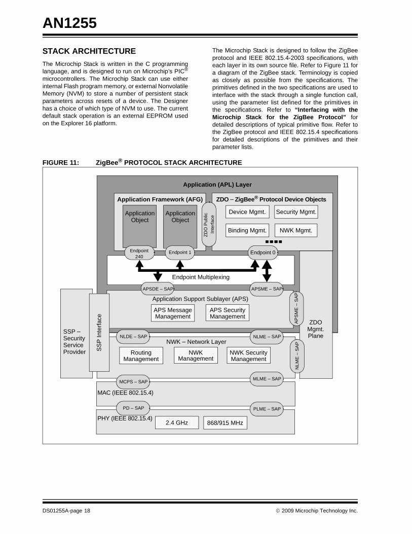
The Microchip Stack is designed to follow the ZigBeeprotocol and IEEE 802.15.4-2003 specifications, witheach layer in its own source file. Refer to Figure 11 fora diagram of the ZigBee stack. Terminology is copiedas closely as possible from the specifications. Theprimitives defined in the two specifications are used tointerface with the stack through a single function call,using the parameter list defined for the primitives inthe specifications. Refer to “Interfacing with theMicrochip Stack for the ZigBee Protocol” fordetailed descriptions of typical primitive flow. Refer tothe ZigBee protocol and IEEE 802.15.4 specificationsfor detailed descriptions of the primitives and theirparameter lists.
FIGURE 11: ZigBee® PROTOCOL STACK ARCHITECTURE
SSP –
Application (APL) Layer
Device Mgmt.
Binding Mgmt.
Security Mgmt.
NWK Mgmt.
Application Framework (AFG) ZDO – ZigBee® Protocol Device Objects
ApplicationObject
ApplicationObject
ZDO
Pub
lic
Inte
rface
Endpoint240
Endpoint 1 Endpoint 0
APSDE – SAP APSME – SAP
ZDOMgmt.Plane
SS
P In
terfa
ce
SecurityServiceProvider
APS Message APS SecurityManagement Management
Routing NWK NWK SecurityManagement Management Management
AP
SM
E –
SA
PN
LME
– S
AP
NLME – SAP
MLME – SAP
PLME – SAP
NLDE – SAP
MCPS – SAP
PD – SAP
2.4 GHz 868/915 MHz
Endpoint Multiplexing
Application Support Sublayer (APS)
NWK – Network Layer
MAC (IEEE 802.15.4)
PHY (IEEE 802.15.4)
DS01255A-page 18 © 2009 Microchip Technology Inc.
AN1255
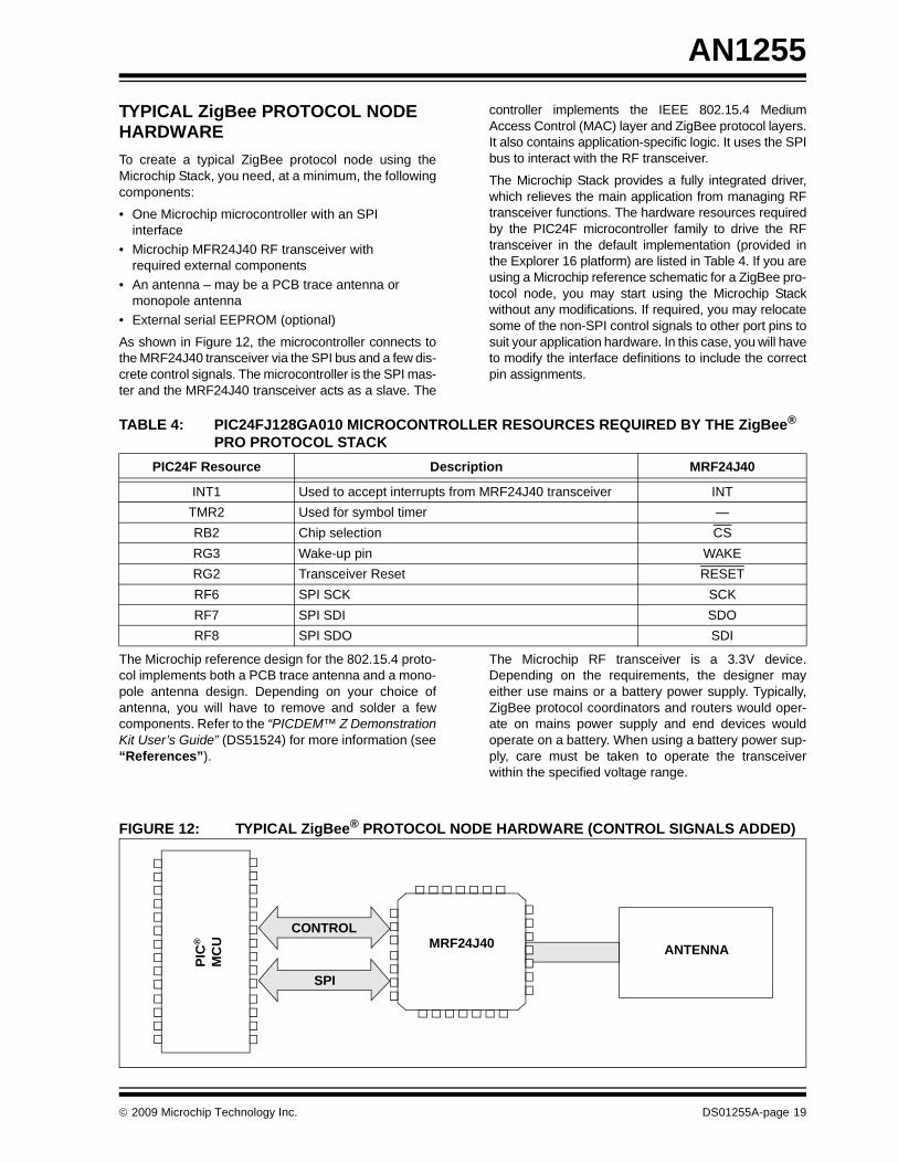
TYPICAL ZigBee PROTOCOL NODE HARDWARETo create a typical ZigBee protocol node using theMicrochip Stack, you need, at a minimum, the followingcomponents:
• One Microchip microcontroller with an SPI interface
• Microchip MFR24J40 RF transceiver with required external components
• An antenna – may be a PCB trace antenna or monopole antenna
• External serial EEPROM (optional)
As shown in Figure 12, the microcontroller connects tothe MRF24J40 transceiver via the SPI bus and a few dis-crete control signals. The microcontroller is the SPI mas-ter and the MRF24J40 transceiver acts as a slave. The
controller implements the IEEE 802.15.4 MediumAccess Control (MAC) layer and ZigBee protocol layers.It also contains application-specific logic. It uses the SPIbus to interact with the RF transceiver.
The Microchip Stack provides a fully integrated driver,which relieves the main application from managing RFtransceiver functions. The hardware resources requiredby the PIC24F microcontroller family to drive the RFtransceiver in the default implementation (provided inthe Explorer 16 platform) are listed in Table 4. If you areusing a Microchip reference schematic for a ZigBee pro-tocol node, you may start using the Microchip Stackwithout any modifications. If required, you may relocatesome of the non-SPI control signals to other port pins tosuit your application hardware. In this case, you will haveto modify the interface definitions to include the correctpin assignments.
TABLE 4: PIC24FJ128GA010 MICROCONTROLLER RESOURCES REQUIRED BY THE ZigBee® PRO PROTOCOL STACK
The Microchip reference design for the 802.15.4 proto-col implements both a PCB trace antenna and a mono-pole antenna design. Depending on your choice ofantenna, you will have to remove and solder a fewcomponents. Refer to the “PICDEM™ Z DemonstrationKit User’s Guide” (DS51524) for more information (see“References”).
The Microchip RF transceiver is a 3.3V device.Depending on the requirements, the designer mayeither use mains or a battery power supply. Typically,ZigBee protocol coordinators and routers would oper-ate on mains power supply and end devices wouldoperate on a battery. When using a battery power sup-ply, care must be taken to operate the transceiverwithin the specified voltage range.
FIGURE 12: TYPICAL ZigBee® PROTOCOL NODE HARDWARE (CONTROL SIGNALS ADDED)
PIC24F Resource Description MRF24J40
INT1 Used to accept interrupts from MRF24J40 transceiver INTTMR2 Used for symbol timer —RB2 Chip selection CSRG3 Wake-up pin WAKERG2 Transceiver Reset RESETRF6 SPI SCK SCKRF7 SPI SDI SDORF8 SPI SDO SDI
PIC
®
ANTENNA
SPI
CONTROL
MC
U MRF24J40
© 2009 Microchip Technology Inc. DS01255A-page 19
AN1255
INSTALLING THE MICROCHIP ZigBee PRO STACKThe complete Microchip Stack source code is availablefor download from the Microchip web site. The sourcecode is distributed in a single Windows® operatingsystem installation file. Perform the following steps tocomplete the installation:
1. Execute the installation file. A Windows operatingsystem installation wizard will guide you throughthe installation process.
2. Before the software is installed, you must acceptthe software license agreement by clicking“I Accept”.
3. After completion of the installation process, youshould see the “Microchip Software Stack forZigBee” protocol program group. The completesource code will be copied in the ZigBeePROsubdirectory in the C:\MicrochipSolutions directory of your computer.
4. Refer to the Readme file distributed with thesource code for the list of enhancements andlimitations of the installed version.
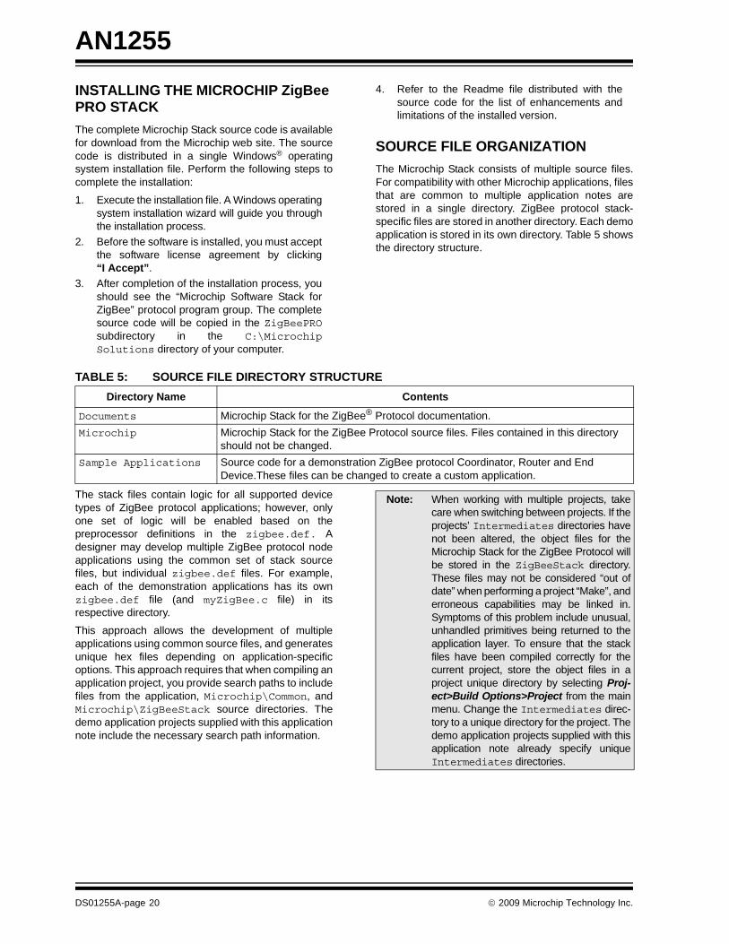
SOURCE FILE ORGANIZATIONThe Microchip Stack consists of multiple source files.For compatibility with other Microchip applications, filesthat are common to multiple application notes arestored in a single directory. ZigBee protocol stack-specific files are stored in another directory. Each demoapplication is stored in its own directory. Table 5 showsthe directory structure.
TABLE 5: SOURCE FILE DIRECTORY STRUCTURE
The stack files contain logic for all supported devicetypes of ZigBee protocol applications; however, onlyone set of logic will be enabled based on thepreprocessor definitions in the zigbee.def. Adesigner may develop multiple ZigBee protocol nodeapplications using the common set of stack sourcefiles, but individual zigbee.def files. For example,each of the demonstration applications has its ownzigbee.def file (and myZigBee.c file) in itsrespective directory.
This approach allows the development of multipleapplications using common source files, and generatesunique hex files depending on application-specificoptions. This approach requires that when compiling anapplication project, you provide search paths to includefiles from the application, Microchip\Common, andMicrochip\ZigBeeStack source directories. Thedemo application projects supplied with this applicationnote include the necessary search path information.
Directory Name Contents
Documents Microchip Stack for the ZigBee® Protocol documentation.Microchip Microchip Stack for the ZigBee Protocol source files. Files contained in this directory
should not be changed.Sample Applications Source code for a demonstration ZigBee protocol Coordinator, Router and End
Device.These files can be changed to create a custom application.
Note: When working with multiple projects, takecare when switching between projects. If theprojects’ Intermediates directories havenot been altered, the object files for theMicrochip Stack for the ZigBee Protocol willbe stored in the ZigBeeStack directory.These files may not be considered “out ofdate” when performing a project “Make”, anderroneous capabilities may be linked in.Symptoms of this problem include unusual,unhandled primitives being returned to theapplication layer. To ensure that the stackfiles have been compiled correctly for thecurrent project, store the object files in aproject unique directory by selecting Proj-ect>Build Options>Project from the mainmenu. Change the Intermediates direc-tory to a unique directory for the project. Thedemo application projects supplied with thisapplication note already specify uniqueIntermediates directories.
DS01255A-page 20 © 2009 Microchip Technology Inc.
AN1255
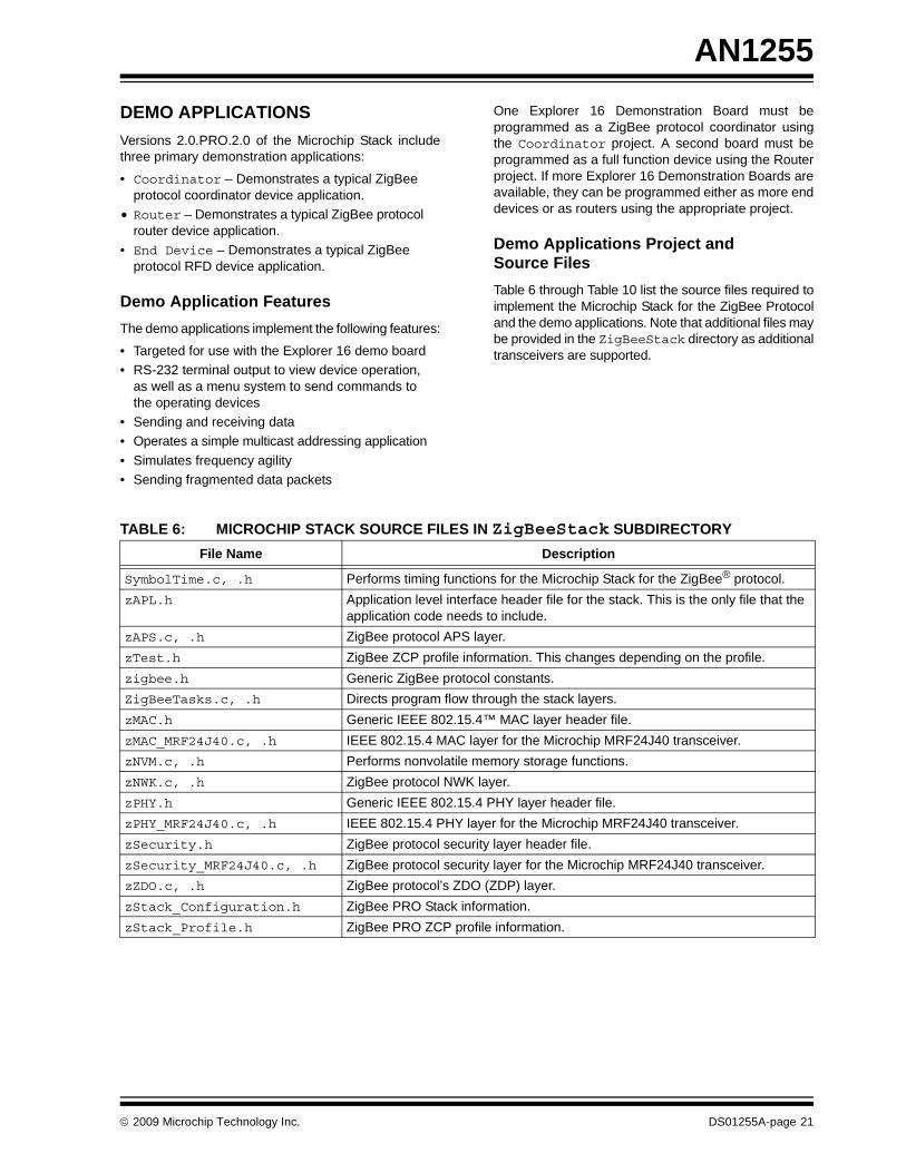
DEMO APPLICATIONSVersions 2.0.PRO.2.0 of the Microchip Stack includethree primary demonstration applications:
• Coordinator – Demonstrates a typical ZigBee protocol coordinator device application.
• Router – Demonstrates a typical ZigBee protocol router device application.
• End Device – Demonstrates a typical ZigBee protocol RFD device application.
Demo Application FeaturesThe demo applications implement the following features:
• Targeted for use with the Explorer 16 demo board• RS-232 terminal output to view device operation,
as well as a menu system to send commands to the operating devices
• Sending and receiving data• Operates a simple multicast addressing application• Simulates frequency agility• Sending fragmented data packets
One Explorer 16 Demonstration Board must beprogrammed as a ZigBee protocol coordinator usingthe Coordinator project. A second board must beprogrammed as a full function device using the Routerproject. If more Explorer 16 Demonstration Boards areavailable, they can be programmed either as more enddevices or as routers using the appropriate project.
Demo Applications Project and Source FilesTable 6 through Table 10 list the source files required toimplement the Microchip Stack for the ZigBee Protocoland the demo applications. Note that additional files maybe provided in the ZigBeeStack directory as additionaltransceivers are supported.
TABLE 6: MICROCHIP STACK SOURCE FILES IN ZigBeeStack SUBDIRECTORYFile Name Description
SymbolTime.c, .h Performs timing functions for the Microchip Stack for the ZigBee® protocol.zAPL.h Application level interface header file for the stack. This is the only file that the
application code needs to include.zAPS.c, .h ZigBee protocol APS layer.zTest.h ZigBee ZCP profile information. This changes depending on the profile.zigbee.h Generic ZigBee protocol constants.ZigBeeTasks.c, .h Directs program flow through the stack layers.zMAC.h Generic IEEE 802.15.4™ MAC layer header file.zMAC_MRF24J40.c, .h IEEE 802.15.4 MAC layer for the Microchip MRF24J40 transceiver.zNVM.c, .h Performs nonvolatile memory storage functions.zNWK.c, .h ZigBee protocol NWK layer.zPHY.h Generic IEEE 802.15.4 PHY layer header file.zPHY_MRF24J40.c, .h IEEE 802.15.4 PHY layer for the Microchip MRF24J40 transceiver.zSecurity.h ZigBee protocol security layer header file.zSecurity_MRF24J40.c, .h ZigBee protocol security layer for the Microchip MRF24J40 transceiver.zZDO.c, .h ZigBee protocol’s ZDO (ZDP) layer.zStack_Configuration.h ZigBee PRO Stack information.zStack_Profile.h ZigBee PRO ZCP profile information.
© 2009 Microchip Technology Inc. DS01255A-page 21
AN1255
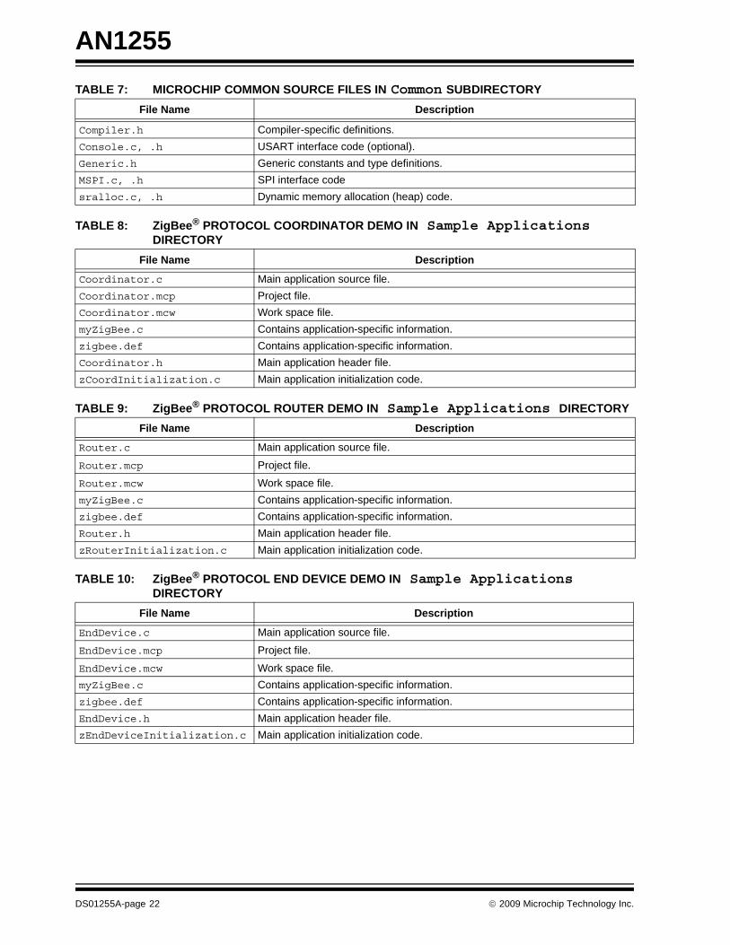
TABLE 7: MICROCHIP COMMON SOURCE FILES IN Common SUBDIRECTORYTABLE 8: ZigBee® PROTOCOL COORDINATOR DEMO IN Sample Applications DIRECTORY
TABLE 9: ZigBee® PROTOCOL ROUTER DEMO IN Sample Applications DIRECTORY
TABLE 10: ZigBee® PROTOCOL END DEVICE DEMO IN Sample Applications DIRECTORY
File Name Description
Compiler.h Compiler-specific definitions.Console.c, .h USART interface code (optional).Generic.h Generic constants and type definitions.MSPI.c, .h SPI interface codesralloc.c, .h Dynamic memory allocation (heap) code.
File Name Description
Coordinator.c Main application source file.Coordinator.mcp Project file.Coordinator.mcw Work space file.myZigBee.c Contains application-specific information.zigbee.def Contains application-specific information.Coordinator.h Main application header file.zCoordInitialization.c Main application initialization code.
File Name Description
Router.c Main application source file.
Router.mcp Project file.
Router.mcw Work space file.myZigBee.c Contains application-specific information.zigbee.def Contains application-specific information.Router.h Main application header file.zRouterInitialization.c Main application initialization code.
File Name Description
EndDevice.c Main application source file.
EndDevice.mcp Project file.
EndDevice.mcw Work space file.myZigBee.c Contains application-specific information.zigbee.def Contains application-specific information.EndDevice.h Main application header file.zEndDeviceInitialization.c Main application initialization code.
DS01255A-page 22 © 2009 Microchip Technology Inc.
AN1255
Demonstrating Sample ApplicationsPlease consult the ZigBeePROQuickStartGuide.pdfand ZigBeePROQuickStartGuide.chm documents inthe stack install directory for a complete guide on howto run the sample applications that came with this ver-sion of the stack.USING THE MICROCHIP STACK FOR THE ZigBee PROTOCOLTo design a ZigBee protocol system, you must do thefollowing:
1. Obtain an Organizationally Unique Identifier(OUI).
2. Determine the radio needed based on data rateand geographical market needs.
3. Select a suitable Microchip MCU.4. Develop the ZigBee protocol application using
the stack provided application note.5. Perform all RF compliance certifications.6. Perform ZigBee protocol interoperability
compliance certification.
Follow these basic steps to develop a ZigBee protocolapplication:
1. Determine the profile that the system will use.2. Determine the endpoint structure that each
device will use.3. Create a new project directory. Place all
application-specific source files and projectfiles in this directory.
4. Make appropriate changes to the ZigBee.deffile as needed based on your specific hardwarerequirements.
5. Use the sample application that came with thestack as a guide in creating a new application.
6. Add code in the new application, including extrainitialization, any required ZDO responsehandling, endpoint message reception andtransmission, and any non-protocol processingand interrupt handling.
The ZigBee Stack Nonvolatile StorageThe ZigBee protocol requires many parameters andtables be storage in Nonvolatile Memory (NVM) so thatinformation critical to the device’s deployment andoperation may be recovered across device resets orpower failures. The Microchip ZigBee PRO Stack uti-lizes the external 25LC256 (32K x 8) serial EEPROMthat is available on the Explorer 16 platform for this pur-pose. It interfaces with the PIC24 microcontroller viathe SPI interface. Other types of NVM devices may beused by the application developer, provided that theappropriate support driver utility is used.
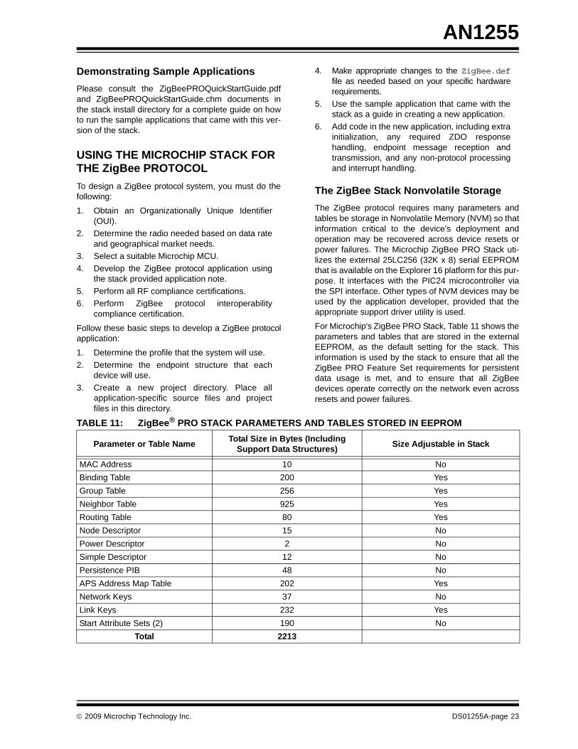
For Microchip's ZigBee PRO Stack, Table 11 shows theparameters and tables that are stored in the externalEEPROM, as the default setting for the stack. Thisinformation is used by the stack to ensure that all theZigBee PRO Feature Set requirements for persistentdata usage is met, and to ensure that all ZigBeedevices operate correctly on the network even acrossresets and power failures.
TABLE 11: ZigBee® PRO STACK PARAMETERS AND TABLES STORED IN EEPROM
Parameter or Table Name Total Size in Bytes (Including Support Data Structures) Size Adjustable in Stack
MAC Address 10 NoBinding Table 200 YesGroup Table 256 YesNeighbor Table 925 YesRouting Table 80 YesNode Descriptor 15 NoPower Descriptor 2 NoSimple Descriptor 12 NoPersistence PIB 48 NoAPS Address Map Table 202 YesNetwork Keys 37 NoLink Keys 232 YesStart Attribute Sets (2) 190 No
Total 2213
© 2009 Microchip Technology Inc. DS01255A-page 23
AN1255
Interfacing with the Microchip Stack for the ZigBee ProtocolThe application source code must include the headerfile, zAPL.h , to access the ZigBee protocol functions.#include “zAPL.h”
A ZigBee protocol coordinator application will need tohave one support variable to keep track of the currentprimitive being executed by the stack.
ZIGBEE_PRIMITIVE currentPrimitive;
A ZigBee protocol router or end device will also need tokeep track of the current primitive; but, in addition, it willneed two other support variables to assist in networkdiscovery and joining.
NETWORK_DESCRIPTOR * currentNetworkDescriptor;ZIGBEE_PRIMITIVE currentPrimitive;NETWORK_DESCRIPTOR * NetworkDescriptor;
Next, the application must configure all pins required tointerface with the transceiver. Refer to theZigBee.def file for the labels created for the sup-ported transceivers.
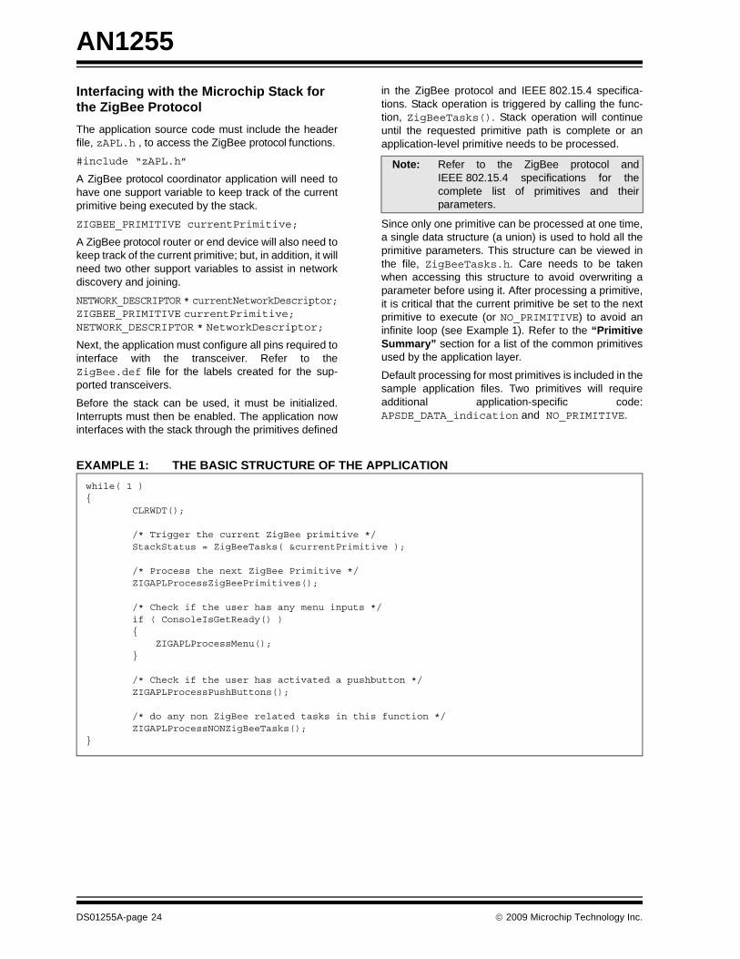
Before the stack can be used, it must be initialized.Interrupts must then be enabled. The application nowinterfaces with the stack through the primitives defined
in the ZigBee protocol and IEEE 802.15.4 specifica-tions. Stack operation is triggered by calling the func-tion, ZigBeeTasks(). Stack operation will continueuntil the requested primitive path is complete or anapplication-level primitive needs to be processed.
Since only one primitive can be processed at one time,a single data structure (a union) is used to hold all theprimitive parameters. This structure can be viewed inthe file, ZigBeeTasks.h. Care needs to be takenwhen accessing this structure to avoid overwriting aparameter before using it. After processing a primitive,it is critical that the current primitive be set to the nextprimitive to execute (or NO_PRIMITIVE) to avoid aninfinite loop (see Example 1). Refer to the “PrimitiveSummary” section for a list of the common primitivesused by the application layer.
Default processing for most primitives is included in thesample application files. Two primitives will requireadditional application-specific code:APSDE_DATA_indication and NO_PRIMITIVE.
EXAMPLE 1: THE BASIC STRUCTURE OF THE APPLICATION
Note: Refer to the ZigBee protocol andIEEE 802.15.4 specifications for thecomplete list of primitives and theirparameters.
while( 1 ){ CLRWDT(); /* Trigger the current ZigBee primitive */ StackStatus = ZigBeeTasks( ¤tPrimitive ); /* Process the next ZigBee Primitive */ ZIGAPLProcessZigBeePrimitives(); /* Check if the user has any menu inputs */ if ( ConsoleIsGetReady() ) { ZIGAPLProcessMenu(); } /* Check if the user has activated a pushbutton */ ZIGAPLProcessPushButtons(); /* do any non ZigBee related tasks in this function */ ZIGAPLProcessNONZigBeeTasks();}
DS01255A-page 24 © 2009 Microchip Technology Inc.
AN1255
Forming or Joining a NetworkThe process of forming or joining a network is shown inthe sample applications. The process is initiated in theNO_PRIMITIVE primitive handling. If the device is aZigBee protocol coordinator, and if it has not formeda network, then it will begin the process of tryingto form a network by issuing theNLME_NETWORK_FORMATION_request primitive.If the device is not a ZigBee protocol coordinator and itis not currently on a network, it will try to join one. If thedevice has determined that it was previously on anetwork, then it will try to join as an orphan by issuingthe NLME_JOIN_request with the RejoinNetworkparameter set to TRUE. If that fails, or if the device wasnot previously on a network, then it will try to joinas a new node. It will first issue theNLME_NETWORK_DISCOVERY_request primitive todiscover what networks are available. The applicationcode will then select one of the discovered networksand try to join it by issuing the NLME_JOIN_requestwith the RejoinNetwork parameter set to FALSE.See “ZigBee Protocol Timing” for timing requirementsused during this process.
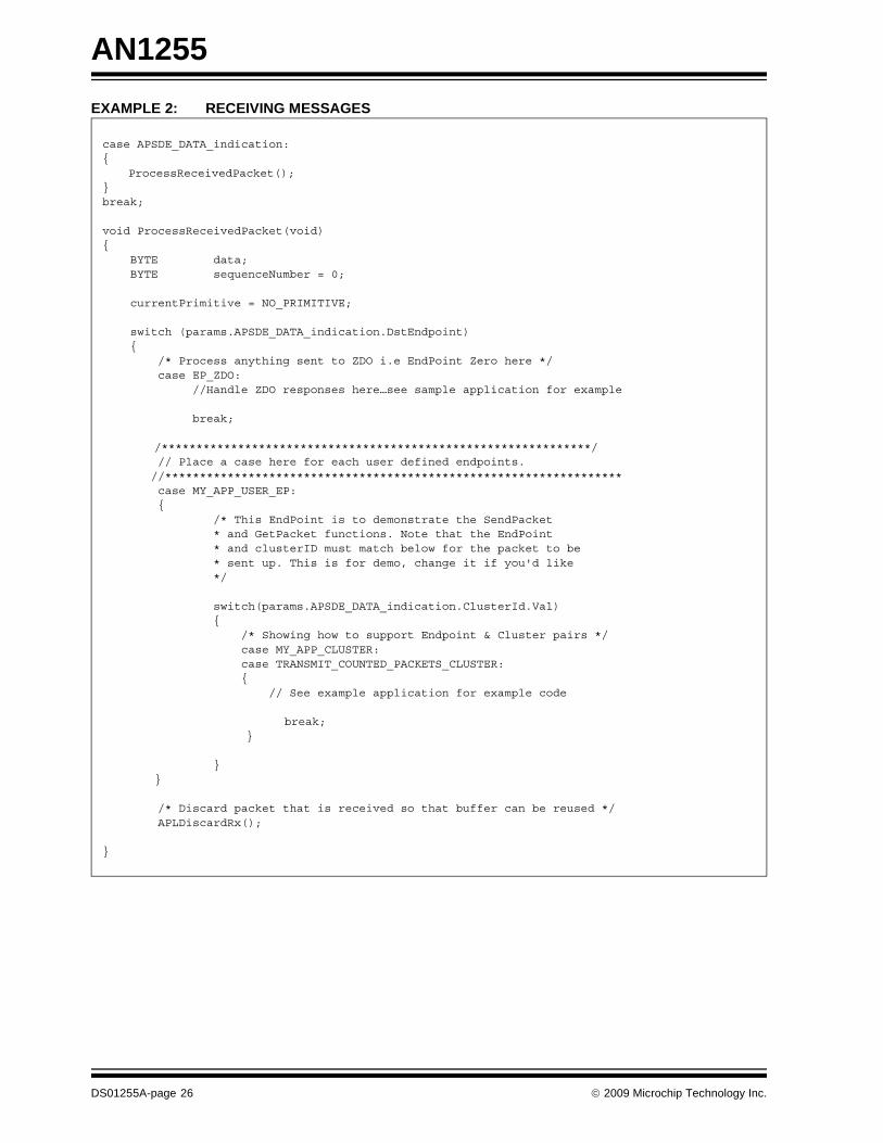
Receiving MessagesThe stack notifies the application of received messagesthrough the APSDE_DATA_indication primitive.When this primitive is returned, theAPSDE_DATA_indication primitive parameters arepopulated with information about the message and thereceived message resides in a buffer. Use the function,APLGet(), to extract each byte of the message fromthe buffer.
The DstEndpoint parameter indicates the destina-tion endpoint for the message. If it is a valid endpoint,the message can be processed (see Example 2).
Note 1: A case for the ZDO endpoint (endpoint 0)must be included to handle responses toall ZDO messages sent by the application.
2: After the message is processed, it mustbe discarded using the APLDiscard()function. Failure to discard the messagewill result in no further messages beingprocessed.
© 2009 Microchip Technology Inc. DS01255A-page 25
AN1255
EXAMPLE 2: RECEIVING MESSAGEScase APSDE_DATA_indication:{
ProcessReceivedPacket();} break;
void ProcessReceivedPacket(void){ BYTE data; BYTE sequenceNumber = 0;
currentPrimitive = NO_PRIMITIVE; switch (params.APSDE_DATA_indication.DstEndpoint) { /* Process anything sent to ZDO i.e EndPoint Zero here */ case EP_ZDO: //Handle ZDO responses here…see sample application for example break;
/**************************************************************/ // Place a case here for each user defined endpoints. //****************************************************************** case MY_APP_USER_EP: { /* This EndPoint is to demonstrate the SendPacket * and GetPacket functions. Note that the EndPoint * and clusterID must match below for the packet to be * sent up. This is for demo, change it if you'd like */ switch(params.APSDE_DATA_indication.ClusterId.Val) { /* Showing how to support Endpoint & Cluster pairs */ case MY_APP_CLUSTER: case TRANSMIT_COUNTED_PACKETS_CLUSTER: { // See example application for example code
break; }
}}
/* Discard packet that is received so that buffer can be reused */ APLDiscardRx();
}
DS01255A-page 26 © 2009 Microchip Technology Inc.

AN1255
The Stack Transmit BufferThe Microchip Stack for the ZigBee PRO Feature Setallows one outgoing message in the application layer ata time. That message is placed in the Transmit Buffer,referred to in the stack code as TxBuffer, and passeddown through the ZigBee protocols' architectural lay-ers, to the transceiver, where it is eventually transmit-ted over the air. The size of the TxBuffer, as per802.15.4 specifications, is fixed at 127 bytes.Figure 13 shows a diagram of the TxBuffer, and will beused to illustrate how a designer’s application may usethis buffer to transmit messages over the air.
FIGURE 13: THE ZigBee® PRO STACK TRANSMIT BUFFER
The operating dimensions of TxBuffer are governed thefollowing C language parameter definitions:#define TX_BUFFER_SIZE 128
#define TX_DATA_START 0
#define TX_HEADER_START (TX_BUFFER_SIZE-1)
BYTE TxBuffer[TX_BUFFER_SIZE]; /* thetransmit buffer */
BYTE TxData = TX_DATA_START; /* theData section */
BYTE TxHeader = TX_HEADER_START; /* theHeader section */
From an architectural perspective, the TxBuffer hastwo distinct sections: a Data section and a Header sec-tion. The Data section starts at address offset 0(TX_DATA_START) and grows toward higher offsets,1, 2, 3 etc., The Header section starts at address offset127 ((TX_BUFFER_SIZE-1), and decreases towardlower offsets: 126, 125, 124, etc.
In terms of the ZigBee protocol, a messages' payloaddata is placed in the Data section, while the message’sheader information is placed in the Header section.The TxData and TxHeader parameters are simply usedby the stack as indexes into the Data and Header sec-tions of the TxBuffer, respectively.
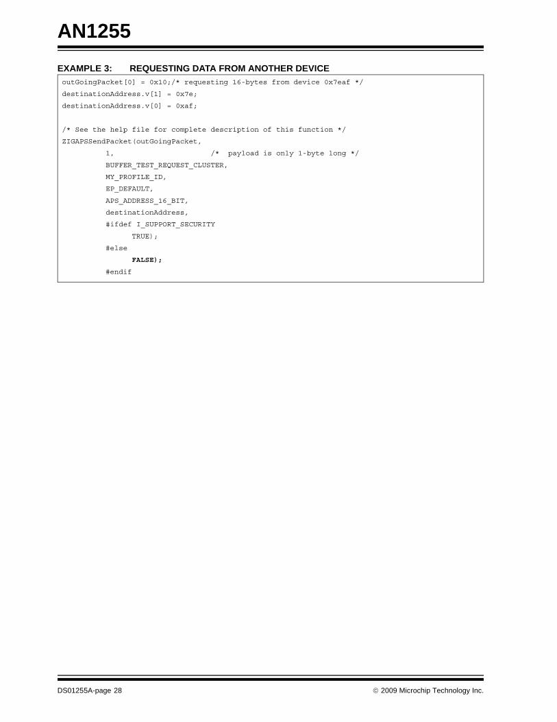
The following code fragment shows how a user’s appli-cation code sets up the transmit buffer to send out aZigBee defined message (i.e. aBUFFER_TEST_REQUEST) to ask the device with anetwork address of 0x7eaf for sixteen (0x10) bytes ofdata.
0
127
TX_DATA_START
TX_HEADER_START
TxData++
TxHeader--
TxBuffer
© 2009 Microchip Technology Inc. DS01255A-page 27
AN1255
EXAMPLE 3: REQUESTING DATA FROM ANOTHER DEVICEoutGoingPacket[0] = 0x10;/* requesting 16-bytes from device 0x7eaf */destinationAddress.v[1] = 0x7e;
destinationAddress.v[0] = 0xaf;
/* See the help file for complete description of this function */
ZIGAPSSendPacket(outGoingPacket,
1, /* payload is only 1-byte long */
BUFFER_TEST_REQUEST_CLUSTER,
MY_PROFILE_ID,
EP_DEFAULT,
APS_ADDRESS_16_BIT,
destinationAddress,
#ifdef I_SUPPORT_SECURITY
TRUE);
#else
FALSE);
#endif
DS01255A-page 28 © 2009 Microchip Technology Inc.
AN1255
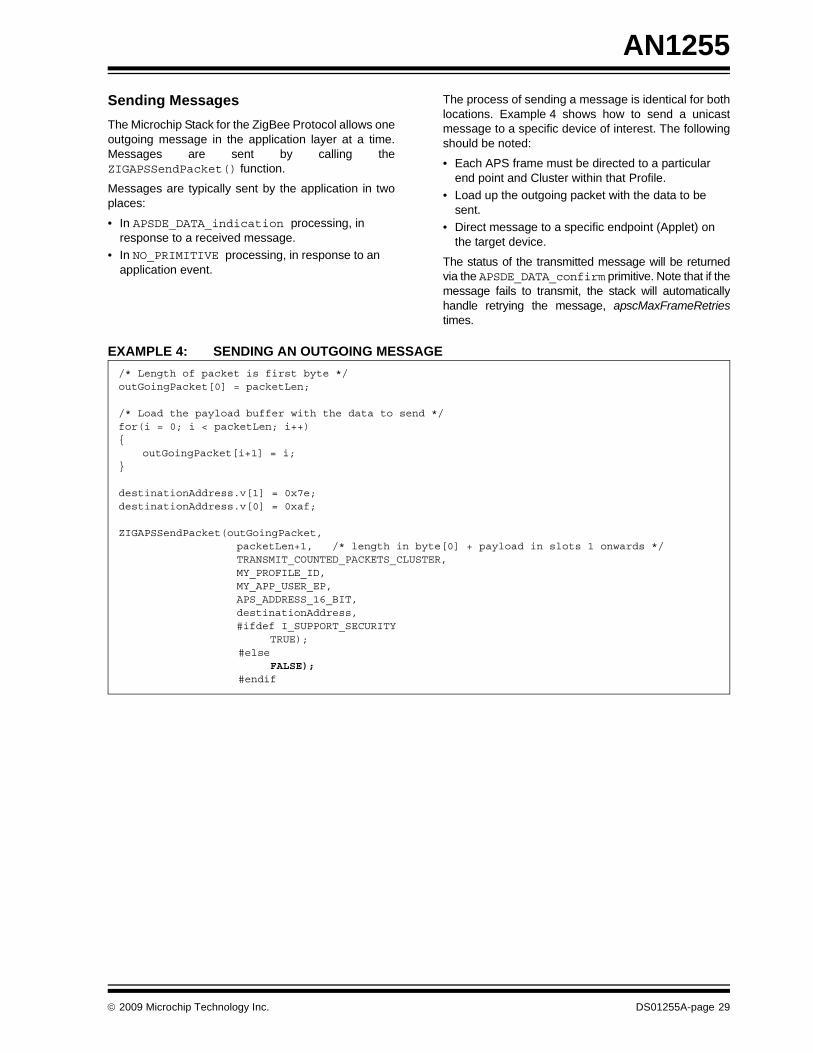
Sending MessagesThe Microchip Stack for the ZigBee Protocol allows oneoutgoing message in the application layer at a time.Messages are sent by calling theZIGAPSSendPacket() function.Messages are typically sent by the application in twoplaces:
• In APSDE_DATA_indication processing, in response to a received message.
• In NO_PRIMITIVE processing, in response to an application event.
The process of sending a message is identical for bothlocations. Example 4 shows how to send a unicastmessage to a specific device of interest. The followingshould be noted:
• Each APS frame must be directed to a particular end point and Cluster within that Profile.
• Load up the outgoing packet with the data to be sent.
• Direct message to a specific endpoint (Applet) on the target device.
The status of the transmitted message will be returnedvia the APSDE_DATA_confirm primitive. Note that if themessage fails to transmit, the stack will automaticallyhandle retrying the message, apscMaxFrameRetriestimes.
EXAMPLE 4: SENDING AN OUTGOING MESSAGE/* Length of packet is first byte */outGoingPacket[0] = packetLen;
/* Load the payload buffer with the data to send */for(i = 0; i < packetLen; i++){
outGoingPacket[i+1] = i;}
destinationAddress.v[1] = 0x7e;destinationAddress.v[0] = 0xaf; ZIGAPSSendPacket(outGoingPacket,
packetLen+1, /* length in byte[0] + payload in slots 1 onwards */ TRANSMIT_COUNTED_PACKETS_CLUSTER, MY_PROFILE_ID, MY_APP_USER_EP, APS_ADDRESS_16_BIT, destinationAddress, #ifdef I_SUPPORT_SECURITY
TRUE); #else FALSE); #endif
© 2009 Microchip Technology Inc. DS01255A-page 29
AN1255
Secure TransmissionThe Microchip Stack for the ZigBee Protocol supportsall seven security modes that are defined in the ZigBeeprotocol specification to protect the output packets.The security modes can be categorized into threegroups:
• Message Integrity Code (MIC) – Security modes ensure the integrity of the packet. The MIC attached to the packet (the size of which is deter-mined by the particular mode) ensures that the packet, including the header and payload, has not been modified in any way during transmission. The packet payload is not encrypted in these modes.
• Encryption (ENC) – Security mode encrypts the payload. The plaintext content of the payload can-not be exposed without a valid security key. This mode cannot verify frame integrity or the content of the header, including the source of the original packet and the frame counter.
• ENC-MIC – Security modes are a combination of the two previous groups. In these modes, the pay-load is encrypted. At the same time, the header and payload’s integrity is protected by the MIC attached at the end of the packet.
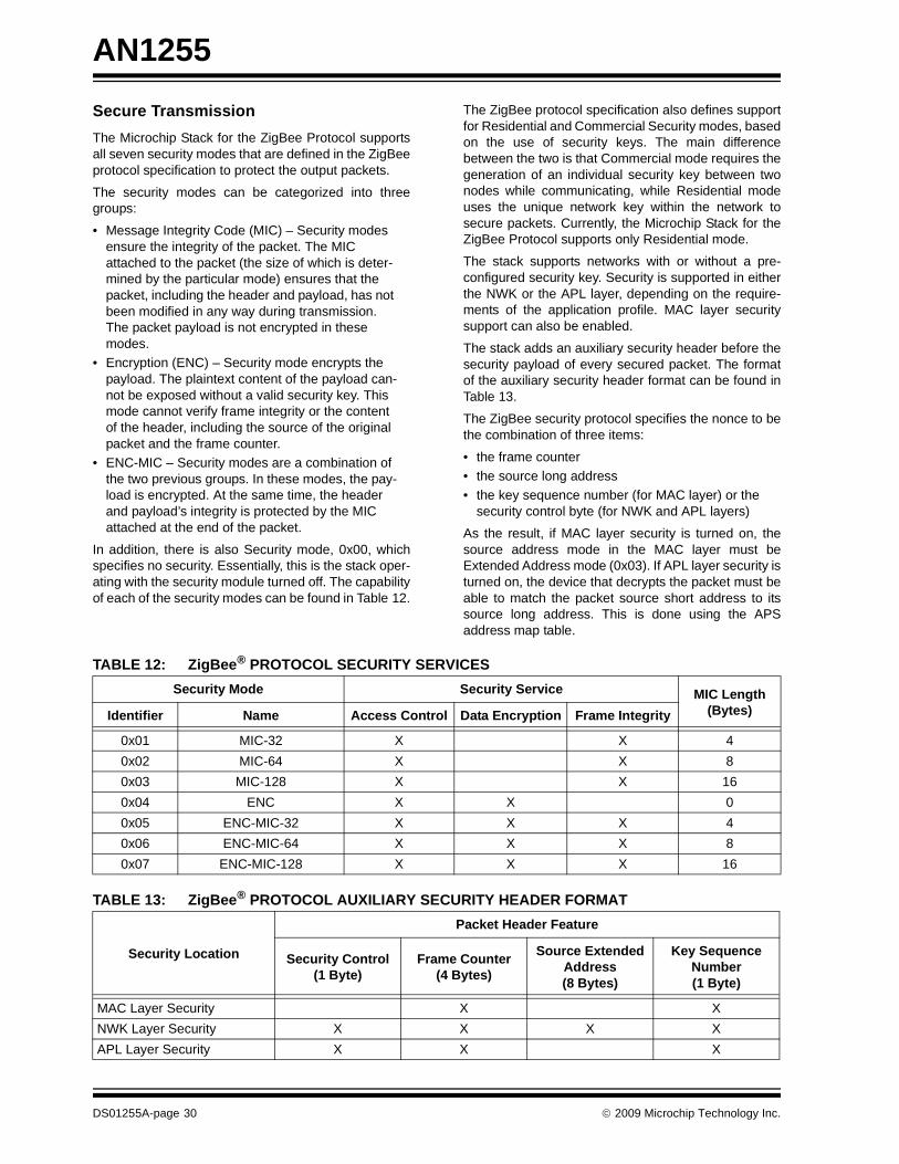
In addition, there is also Security mode, 0x00, whichspecifies no security. Essentially, this is the stack oper-ating with the security module turned off. The capabilityof each of the security modes can be found in Table 12.
The ZigBee protocol specification also defines supportfor Residential and Commercial Security modes, basedon the use of security keys. The main differencebetween the two is that Commercial mode requires thegeneration of an individual security key between twonodes while communicating, while Residential modeuses the unique network key within the network tosecure packets. Currently, the Microchip Stack for theZigBee Protocol supports only Residential mode.
The stack supports networks with or without a pre-configured security key. Security is supported in eitherthe NWK or the APL layer, depending on the require-ments of the application profile. MAC layer securitysupport can also be enabled.
The stack adds an auxiliary security header before thesecurity payload of every secured packet. The formatof the auxiliary security header format can be found inTable 13.
The ZigBee security protocol specifies the nonce to bethe combination of three items:
• the frame counter • the source long address • the key sequence number (for MAC layer) or the
security control byte (for NWK and APL layers)
As the result, if MAC layer security is turned on, thesource address mode in the MAC layer must beExtended Address mode (0x03). If APL layer security isturned on, the device that decrypts the packet must beable to match the packet source short address to itssource long address. This is done using the APSaddress map table.
TABLE 12: ZigBee® PROTOCOL SECURITY SERVICES
TABLE 13: ZigBee® PROTOCOL AUXILIARY SECURITY HEADER FORMAT
Security Mode Security Service MIC Length (Bytes)Identifier Name Access Control Data Encryption Frame Integrity
0x01 MIC-32 X X 40x02 MIC-64 X X 80x03 MIC-128 X X 160x04 ENC X X 00x05 ENC-MIC-32 X X X 40x06 ENC-MIC-64 X X X 80x07 ENC-MIC-128 X X X 16
Security Location
Packet Header Feature
Security Control (1 Byte)
Frame Counter (4 Bytes)
Source Extended Address (8 Bytes)
Key Sequence Number (1 Byte)
MAC Layer Security X XNWK Layer Security X X X XAPL Layer Security X X X
DS01255A-page 30 © 2009 Microchip Technology Inc.
AN1255
The stack is capable of ensuring sequential freshnessby checking the transmitted frame counter. Only theframe counter of packets from family members (parentor children) will be checked, since only family memberknows when a device joins the network. Packets thatare from family members but do not meet thesequential freshness requirement will be discarded.The maximum length of a transmitted message is127 bytes. When the security module is turned on,between 5 and 29 additional bytes are required for theauxiliary security header and the MIC, depending onthe combination of security mode and secured layer.Users will need to balance the security needs and theimpact on the data payload size (and associated perfor-mance impact) associated with the combination ofsecurity settings.
The security mode and secured layer settings aredefined in the application profile.
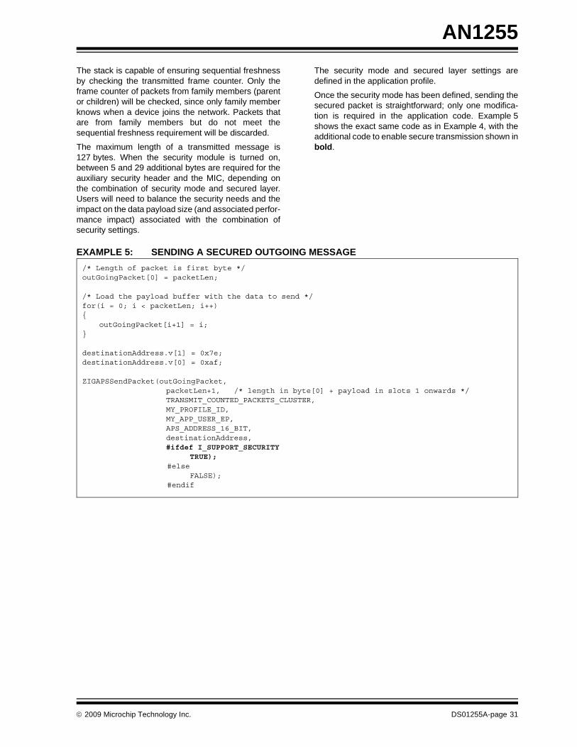
Once the security mode has been defined, sending thesecured packet is straightforward; only one modifica-tion is required in the application code. Example 5shows the exact same code as in Example 4, with theadditional code to enable secure transmission shown inbold.
EXAMPLE 5: SENDING A SECURED OUTGOING MESSAGE/* Length of packet is first byte */outGoingPacket[0] = packetLen;
/* Load the payload buffer with the data to send */for(i = 0; i < packetLen; i++){
outGoingPacket[i+1] = i;}
destinationAddress.v[1] = 0x7e;destinationAddress.v[0] = 0xaf; ZIGAPSSendPacket(outGoingPacket,
packetLen+1, /* length in byte[0] + payload in slots 1 onwards */ TRANSMIT_COUNTED_PACKETS_CLUSTER, MY_PROFILE_ID, MY_APP_USER_EP, APS_ADDRESS_16_BIT, destinationAddress, #ifdef I_SUPPORT_SECURITY
TRUE); #else FALSE); #endif
© 2009 Microchip Technology Inc. DS01255A-page 31

AN1255
Primitive SummaryThe application layer communicates with the stack pri-marily through the primitives defined in the ZigBee pro-tocol and IEEE 802.15.4 specifications. Table 14describes the primitives that are commonly issued bythe application layer and their response primitive. Notall devices will issue all of these primitives.Some primitives that are received by the applicationlayer are generated by the stack itself, not as aresponse to an application primitive. The applicationlayer must be able to handle these primitives as well.Table 15 shows all the primitives that can be returnedto the application layer. Default processing for most ofthe primitives is included in the application templates.
TABLE 14: TYPICAL APPLICATION PRIMITIVES AND RESPONSESApplication Issued Primitive Response Primitive Description
APSDE_DATA_request APSDE_DATA_confirm Used to send messages to other devices.APSME_BIND_request APSME_BIND_confirm Force the creating of a binding. Can be used only
on devices that support binding. APSME_UNBIND_request APSME_UNBIND_confirm Force the removal of a binding. Can be used only
on devices that support binding. NLME_NETWORK_DISCOVERY_request
NLME_NETWORK_DISCOVERY_confirm
Discover networks available for joining. Not used by ZigBee® protocol coordinators.
NLME_NETWORK_FORMATION_request
NLME_NETWORK_FORMATION_confirm
Start a network on one of the specified channels. ZigBee protocol coordinators only.
NLME_PERMIT_JOINING_request
NLME_PERMIT_JOINING_confirm
Allow other nodes to join the network as our children. ZigBee protocol coordinators and routers only.
NLME_START_ROUTER_request
NLME_START_ROUTER_confirm
Start routing functionality. Routers only.
NLME_JOIN_request NLME_JOIN_confirm Try to rejoin or join the specified network. Not used by ZigBee protocol coordinators.
NLME_DIRECT_JOIN_request
NLME_DIRECT_JOIN_confirm
Add a device as a child device. ZigBee protocol coordinators and routers only.
NLME_LEAVE_request NLME_LEAVE_confirm Leave the network or force a child device to leave the network.
NLME_SYNC_request NLME_SYNC_confirm Request buffered messages from the device’s parent. RFDs only.
APSME_ADD_GROUP_request APSME_ADD_GROUP_confirm Request membership in particular group to an end-point. Can be used only on devices that support multicast addressing.
APSME_REMOVE_GROUP_request
APSME_REMOVE_GROUP_confirm
Remove membership in particular group from an endpoint. Can be used only on devices that sup-port multicast addressing.
APSME_REMOVE_ALL_GROUPS_request
APSME_REMOVE_ALL_GROUPS_confirm
Remove membership in all groups from an end-point. Can be used only on devices that support multicast addressing.
NETWORK_ROUTE_DISCOVERY_request
NETWORK_ROUTE_DISCOVERY_confirm
Initiate route discovery to another device. ZigBee protocol Coordinator and Routers only.
DS01255A-page 32 © 2009 Microchip Technology Inc.
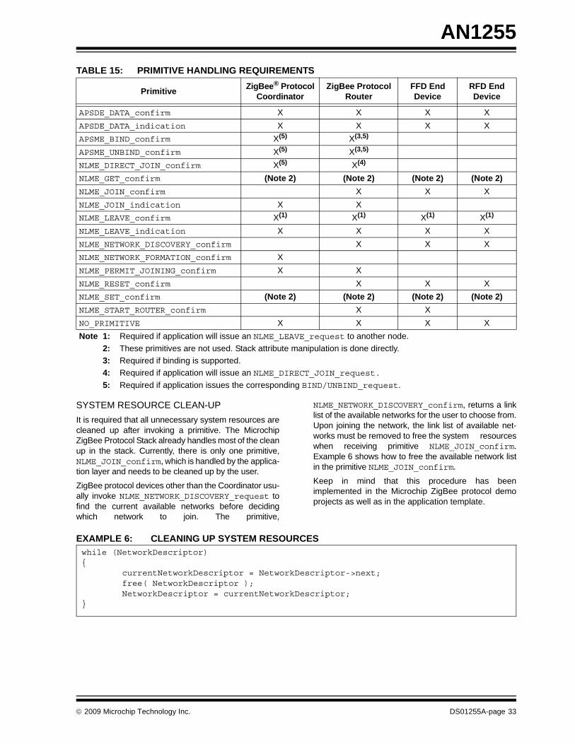
AN1255
TABLE 15: PRIMITIVE HANDLING REQUIREMENTSSYSTEM RESOURCE CLEAN-UPIt is required that all unnecessary system resources arecleaned up after invoking a primitive. The MicrochipZigBee Protocol Stack already handles most of the cleanup in the stack. Currently, there is only one primitive,NLME_JOIN_confirm, which is handled by the applica-tion layer and needs to be cleaned up by the user.
ZigBee protocol devices other than the Coordinator usu-ally invoke NLME_NETWORK_DISCOVERY_request tofind the current available networks before decidingwhich network to join. The primitive,
NLME_NETWORK_DISCOVERY_confirm, returns a linklist of the available networks for the user to choose from.Upon joining the network, the link list of available net-works must be removed to free the system resourceswhen receiving primitive NLME_JOIN_confirm.Example 6 shows how to free the available network listin the primitive NLME_JOIN_confirm.
Keep in mind that this procedure has beenimplemented in the Microchip ZigBee protocol demoprojects as well as in the application template.
EXAMPLE 6: CLEANING UP SYSTEM RESOURCES
Primitive ZigBee® Protocol Coordinator
ZigBee Protocol Router
FFD End Device
RFD End Device
APSDE_DATA_confirm X X X XAPSDE_DATA_indication X X X XAPSME_BIND_confirm X(5) X(3,5)
APSME_UNBIND_confirm X(5) X(3,5)
NLME_DIRECT_JOIN_confirm X(5) X(4)
NLME_GET_confirm (Note 2) (Note 2) (Note 2) (Note 2)NLME_JOIN_confirm X X XNLME_JOIN_indication X XNLME_LEAVE_confirm X(1) X(1) X(1) X(1)
NLME_LEAVE_indication X X X XNLME_NETWORK_DISCOVERY_confirm X X XNLME_NETWORK_FORMATION_confirm XNLME_PERMIT_JOINING_confirm X XNLME_RESET_confirm X X XNLME_SET_confirm (Note 2) (Note 2) (Note 2) (Note 2)NLME_START_ROUTER_confirm X XNO_PRIMITIVE X X X XNote 1: Required if application will issue an NLME_LEAVE_request to another node.
2: These primitives are not used. Stack attribute manipulation is done directly.3: Required if binding is supported.4: Required if application will issue an NLME_DIRECT_JOIN_request.5: Required if application issues the corresponding BIND/UNBIND_request.
while (NetworkDescriptor){
currentNetworkDescriptor = NetworkDescriptor->next;free( NetworkDescriptor );NetworkDescriptor = currentNetworkDescriptor;
}
© 2009 Microchip Technology Inc. DS01255A-page 33
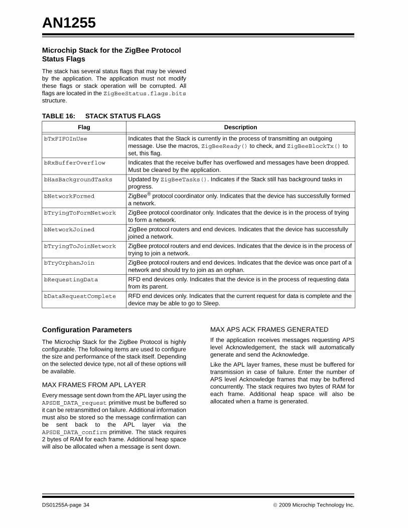
AN1255
Microchip Stack for the ZigBee Protocol Status FlagsThe stack has several status flags that may be viewedby the application. The application must not modifythese flags or stack operation will be corrupted. Allflags are located in the ZigBeeStatus.flags.bitsstructure.TABLE 16: STACK STATUS FLAGS
Configuration ParametersThe Microchip Stack for the ZigBee Protocol is highlyconfigurable. The following items are used to configurethe size and performance of the stack itself. Dependingon the selected device type, not all of these options willbe available.
MAX FRAMES FROM APL LAYEREvery message sent down from the APL layer using theAPSDE_DATA_request primitive must be buffered soit can be retransmitted on failure. Additional informationmust also be stored so the message confirmation canbe sent back to the APL layer via theAPSDE_DATA_confirm primitive. The stack requires2 bytes of RAM for each frame. Additional heap spacewill also be allocated when a message is sent down.
MAX APS ACK FRAMES GENERATEDIf the application receives messages requesting APSlevel Acknowledgement, the stack will automaticallygenerate and send the Acknowledge.
Like the APL layer frames, these must be buffered fortransmission in case of failure. Enter the number ofAPS level Acknowledge frames that may be bufferedconcurrently. The stack requires two bytes of RAM foreach frame. Additional heap space will also beallocated when a frame is generated.
Flag Description
bTxFIFOInUse Indicates that the Stack is currently in the process of transmitting an outgoing message. Use the macros, ZigBeeReady() to check, and ZigBeeBlockTx() to set, this flag.
bRxBufferOverflow Indicates that the receive buffer has overflowed and messages have been dropped. Must be cleared by the application.
bHasBackgroundTasks Updated by ZigBeeTasks(). Indicates if the Stack still has background tasks in progress.
bNetworkFormed ZigBee® protocol coordinator only. Indicates that the device has successfully formed a network.
bTryingToFormNetwork ZigBee protocol coordinator only. Indicates that the device is in the process of trying to form a network.
bNetworkJoined ZigBee protocol routers and end devices. Indicates that the device has successfully joined a network.
bTryingToJoinNetwork ZigBee protocol routers and end devices. Indicates that the device is in the process of trying to join a network.
bTryOrphanJoin ZigBee protocol routers and end devices. Indicates that the device was once part of a network and should try to join as an orphan.
bRequestingData RFD end devices only. Indicates that the device is in the process of requesting data from its parent.
bDataRequestComplete RFD end devices only. Indicates that the current request for data is complete and the device may be able to go to Sleep.
DS01255A-page 34 © 2009 Microchip Technology Inc.
AN1255
MAX APS ADDRESSESAlthough all normal messaging between nodes is doneusing 16-bit network addresses, the ZigBee protocolspecification allows the APSDE_DATA_request primi-tive to be invoked with a 64-bit MAC address as themessage destination. If so, the APS layer searches anAPS address map for the 16-bit address of the specifiednode. This table is stored in nonvolatile memory andmust be maintained by the application. Use of this tableis optional. If this value is set to ‘0’, the table is notcreated; no code is created to search the table andAPSDE_DATA_request calls with 64-bit addressing willfail. If this value is not set to ‘0’, the stack requires10 bytes of nonvolatile memory for each entry, plus2 bytes of RAM.MAX BUFFERED INDIRECT MESSAGESIf a device supports bindings (ZigBee protocol coordi-nators, and optionally, ZigBee protocol routers), then itmust buffer all received indirect transmissions so theycan be forwarded to one or more destinations. Thestack requires 2 bytes of RAM for each messagespecified. Additional heap space will also be allocatedwhen an indirect message is received.
BINDING TABLE SIZEIf a device supports bindings, then it must possess abinding table. The stack requires 5 bytes of nonvolatilememory for each binding table entry. Note that the min-imum binding table size is dictated by the stack profile.
NEIGHBOR TABLE SIZEAll devices keep track of other nodes on the network byusing a Neighbor Table. End devices require a Neigh-bor Table to record potential parents. ZigBee protocolcoordinators require a Neighbor Table to record chil-dren. ZigBee protocol routers require a Neighbor Tablefor both functions. The stack requires 15 bytes of non-volatile memory for each Neighbor Table entry. Notethat minimum Neighbor Table size is dictated by thestack profile.
MAX BUFFERED BROADCAST MESSAGESWhen FFDs generate or receive a broadcast message,they must buffer the message while they check for pas-sive Acknowledges in case they must rebroadcast themessage. The stack may be configured as to how manybroadcast messages may be buffered in the system atone time. It is recommended that this value be at leasttwo, since a typical discovery sequence is a broadcastNWK_ADDR_req, followed soon by a broadcast routerequest. The system requires 2 bytes of RAM for eachbuffered broadcast message specified. Additional heapspace will also be allocated when a broadcast messageis received or generated.
MAX NUMBER OF GROUPSIf the device supports Group Addressing, then it musthave a Group Table. This parameter governs the max-imum number of records that the Group Table will sup-port. The stack requires 22 bytes of nonvolatilememory for each Group Table entry.
MAX END POINTS PER GROUPIf the device supports Group Addressing, then eachGroup ID can be associated with up to this manyendpoints.
MAX NUMBER OF DUPLICATE PACKETSAll devices keep track of each packet they receive. Indi-vidual packets are distinguished from each other bytheir unique sequence number. If two packets are thereceived that bear the same sequence number, thesecond packet is tagged as a duplicate and is dis-carded. The number of packet sequence numbers thatare maintained and checked against the latest packetreceived is governed by the parameter.
DUPLICATE TABLE EXPIRATIONThis parameter governs how long a packet sequencenumber is maintained by the device before thesequence number is discarded. If two packets arereceived that bear the same sequence number beforethe first sequence number has expired, the secondpacket is tagged as a duplicate and discarded. Theexpiration time interval for the duplicate packet isgoverned by this parameter.
ROUTE DISCOVERY TABLE SIZEThe ZigBee protocol specification requires that FFDsuse a route discovery table during the route discoveryprocess. Since these entries are required for only ashort time, they are stored in heap memory. Thesystem requires 2 bytes of RAM for each table entryspecified. Additional heap space will also be allocatedwhen route discovery is underway. Note that the mini-mum route discovery table size is dictated by the stackprofile.
ROUTING TABLE SIZEThe ZigBee protocol specification requires that FFDsmaintain a routing table to route messages to othernodes in the network. The system requires 5 bytes ofnonvolatile memory for each entry specified. Note thatthe minimum routing table size is dictated by the stackprofile.
RESERVED ROUTING TABLE ENTRIESThe ZigBee protocol specification requires that FFDsreserve a portion of the routing table for use duringroute repair. Note that the minimum reserved tableentries are dictated by the stack profile.
© 2009 Microchip Technology Inc. DS01255A-page 35
AN1255
MAX BUFFERED ROUTING MESSAGESIf an FFD receives a message that needs to be routed,and the FFD does not have a route for the requireddestination, it must buffer the received message andperform route discovery (if possible) for the requireddestination. The system requires 10 bytes of RAM foreach buffered message specified. Additional heapspace will also be allocated when a message isreceived.CHANNEL ENERGY THRESHOLDWhen a ZigBee protocol coordinator selects a channelfor a new network, it first scans all of the available chan-nels and eliminates those whose channel energyexceeds a specified limit.
MINIMUM JOIN LQIWhen a ZigBee protocol router or end device joins anew network, it examines the link quality of the beaconit received from each possible parent. If the link qualityis below this specified minimum, the device willeliminate that device as a potential parent.
TRANSACTION PERSISTENCEZigBee protocol coordinators and routers are requiredto buffer messages for their children whose transceiv-ers are off when they are Idle. This parameter is theamount of time in seconds that the parent device mustbuffer the messages before it may discard them.
SECURITY MODEThis parameter specifies the use of either Residentialor Commercial Security mode, as defined in the ZigBeeprotocol. The differences between these modes in dis-cussed in “Secure Transmission”. Currently, theMicrochip Stack for the ZigBee Protocol supports onlyResidential mode.
TRUST CENTERThe ZigBee protocol defines the concept of a TrustCenter to coordinate the operations related to security.A trust center must be an FFD, and there can be onlyone trust center in a network. The Trust Center addressmust be defined in the Coordinator as well as in thedevice defined as the Trust Center.
NETWORK KEYThis parameter specifies the 16 byte network securitykey. This key is used to secure the outgoing packets aswell as to decrypt the incoming packets when securityis used in Residential mode. There is also a sequencenumber for the key, used primarily to identify the key,especially if multiple network keys are transferred andused during run time. The Network Key must be pres-ent for Coordinators and the device that acts as thetrust center.
KEY PRESENT IN ALL DEVICES ON THE NETWORKThis parameter is used for Coordinator and Router. Ifthe key is present in all devices on the network, then alldevices must contain the Network Key. By defining thisparameter, it is assumed that all devices already havethe key before joining the network. As a result, the trustcenter sends the joining device a dummy key, and allpackets between devices on the network may beencrypted. If, however, this parameter is not set, thetrust center tries to send the joining device theunprotected security key through the joining device’sparent.
NONVOLATILE STORAGEThe ZigBee protocol requires that many tables bestored in nonvolatile memory. PIC microcontrollers withan allowable erase block size (smaller than 127 forPIC18F devices) may store these in internal programmemory. This is the preferred location, since read andwrite accesses are relatively fast. However, PIC MCUdevices with large erase block sizes, such as thePIC24F devices, must store these values externally.The stack provides support to use an external SPIserial EEPROM to store these values. Since sometransceivers require a dedicated SPI peripheral unlessexternal hardware is provided, the SPI selection maybe disabled depending on transceiver configuration.
When using external nonvolatile memory, it may bedesirable to place each device’s MAC address in theserial EEPROM during production rather than usingSQTP when programming the PIC MCU. If the MACaddress is to be programmed into the serial EEPROMduring the manufacturing process, it should be storedin locations 0 through 7 in the serial EEPROM.
STOCHASTIC_ADDRESSINGThis parameter specifies the use of the device stochas-tic addressing method, instead of the older CSKIPmethod that was employed in the ZigBee-2006 Stack.The ZigBee PRO ZCP profile mandates the use of sto-chastic addressing.
SAS_TABLE_SIZEThis parameter specifies how many Startup AttributeSets (SAS) will be stored in NVM. The default setting is2. Therefore, in addition to a default SAS, two addi-tional instances are maintained in NVM.
Note: If the application is to use security andstore its nonvolatile information externally,the security keys will be stored in the serialEEPROM. The stack will encrypt thesekeys before storing them, using a randomkey generated by the stack configurationtool. Unencrypted keys will not be storedexternally.
DS01255A-page 36 © 2009 Microchip Technology Inc.
AN1255
COMMISSIONINGThis parameter specifies that a Startup Attribute Set(SAS) will be stored in NVM. By design, space isreserved in NVM for three SAS instances and the APIfunctions that support the reading from and writing tothe SAS are included in the builds for each ZigBeedevice type.CONCENTRATORThis ZigBee PRO Feature Set defines the concept of aConcentrator device that is capable of managing many-to-one and source routing. This parameter indicateswhich device has the built-in infrastructure to supportthe requirements of a Concentrator device, such asmaintaining a Route Record Table.
CONCENTRATOR RADIUSWhen a ZigBee PRO Concentrator device collects theroutes to other devices in the network, it does so onlywithin a specified maximum range. This parameterspecifies the neighborhood range, in radius hops, forwhich a given concentrator stores routes. In a largenetwork, this parameter can be used to establish the“neighborhood” in which each Concentrator operates.
HIGH CONCENTRATORThis ZigBee PRO Feature Set defines the concept of aConcentrator device that is capable of managing many-to-one and source routing. This parameter indicatesthat the device has the built-in infrastructure to supportthe requirements of a Concentrator and it maintains aRoute Record Table.
LOW CONCENTRATORThis ZigBee PRO Feature Set defines the concept of aConcentrator device that is capable of managing many-to-one and source routing. This parameter indicatesthat the device has the built-in infrastructure to supportthe requirements of a Concentrator but does not main-tain a Route Record Table. All data requests to this typeof Concentrator must be preceded by a Route RecordCommand.
ROUTE RECORD TABLE SIZEThe ZigBee PRO Feature Set requires that all HighConcentrator devices maintain a Route Record Table inorder to route messages to target devices using sourcerouting. The system requires 240 bytes of RAM for thetable, and the default maximum number of entries thatcan be held in this table is 60.
ROUTING_TABLE_AGINGThe Link Status Command is used to update both theneighbor and routing table entries. If it is determinedthat a device has moved or is no longer on the network,this parameter is used to decide when its entry in therouting table would be removed.
FRAGMENTATIONThe ZigBee PRO Feature Set allows for the transmis-sion of packets that will exceed the 127-byte packetlength set forth in the 802.15.4 specifications. Thisparameter is used to allow the stack to support thechopping up of larger packets into smaller transmittableblocks that are reassembled at the receiver. If thisparameter is not set, then fragmentation is disabled.
FREQUENCY_AGILITYThis parameter is used to specify support for the fre-quency agility feature. If not specified, then thedynamic channel change and notification mechanismwithin the stack will be disabled.
PANID_CONFLICTThis parameter is used to specify support for the PANIDconflict detection and resolution mechanism. If notspecified, then PANID conflicts are ignored and notifi-cations are not sent to the channel manager.
PRECONFIGURED_LINK_KEYThis parameter specifies the 16-bit application linksecurity key. This key is used to secure the outgoingpackets as well as to decrypt the incoming packets atthe application level when the high security mode isused. The Link Key must be present for Coordinatorsand the device that acts as the trust center.
HEAP SIZEThe Microchip Stack uses dynamic memory allocation formany purposes, including those listed in Table 17. RFDend devices may be able to have as little as one bank ofheap space. FFDs should have as much space as possi-ble. FFDs with child devices whose transceivers are offwhen Idle are required to be able to buffer one or moremessages for each child. Refer to the appropriate stackprofile for the exact requirement. Heap space will also berequired based on the settings above. The selected heapsize should take all of these items into consideration,and, therefore, is very application dependent.
© 2009 Microchip Technology Inc. DS01255A-page 37

AN1255
TABLE 17: HEAP USAGEZigBee Protocol TimingThe data rate for 2.4 GHz operation is 250 kbps. Fourdata bits are transferred during each symbol period. Asymbol period is, therefore, 16 microseconds. Internalstack timing is based off of the symbol period.
Both beacon and non-beacon networks have timingsthat are based off superframes, even though the super-frame is not used in non-beacon networks. The super-frame duration (aBaseSuperframeDuration) is thenumber of symbols that form a superframe slot(aBaseSlotDuration, 60) multiplied by the number ofslots contained in a superframe (aNumSuperframeSlots,16). The scan duration requiredby the NLME_NETWORK_DISCOVERY_request,NLME_NETWORK_FORMATION_request, andNLME_JOIN_request primitives is (aBaseSuperframe-Duration * (2n + 1)) symbols, where n is the value of theScanDuration parameter. For the Microchip Stack,ScanDuration can be between 0 and 14, making thescan time between 0.031 seconds and 4.2 minutes.
For other frequency bands, refer to the IEEE specifica-tions for the data rate. The other times can be calculatedfrom that.
CONCLUSIONThe Microchip Stack for the ZigBee Protocol provides amodular, easy-to-use library that is application andRTOS independent. It is specifically designed to sup-port more than one RF transceiver with minimalchanges to upper layer software. Applications can beeasily ported from one RF transceiver to another. It istargeted for the MPLAB C Compiler for PIC24 MCUsand dsPIC® DSCs, but it can be easily modified to sup-port other compilers.
REFERENCES• “ZigBee® Protocol Specification”
http://www.zigbee.org• “IEEE 802.15.4™ Specification”
http://www.ieee.org
SOURCE CODEThe complete source code, including demo applica-tions, is available from microchipDIRECT.
Description LayerZigBee® Protocol
Coordinator
ZigBee Protocol Router
FFD End Device
RFD End Device
Checking for descriptor matching ZDO X X X XChecking for end device bind matching ZDO X X(1)
Buffering messages received from the APL APS X X X XBuffering received indirect messages for retransmission APS X X(1)
Buffering route requests for rebroadcast NWK X X XBuffering other broadcast messages for rebroadcast NWK X X XBuffering channel information on network formation NWK XBuffering network information on network join NWK X X XRoute discovery table entries NWK X X XBuffering messages that require routing NWK X X XBuffering messages for RFD children in Sleep MAC X XBuffering a received message PHY X X X XNonvolatile memory manipulation NVM X X X XTemporary security data during encryption process SEC X X X XNote 1: If binding is supported.
DS01255A-page 38 © 2009 Microchip Technology Inc.
AN1255
ANSWERS TO FREQUENTLY ASKED QUESTIONS (FAQs)Q: Is the Microchip Stack for the ZigBee Protocol a
ZigBee protocol compliant platform?A: Yes.
Q: I want to use a wireless protocol, but I do notwant all of the ZigBee protocol features. May Imodify the Microchip Stack for my own usewithout receiving any further permissions?
A: No. Microchip has the relevant license rights todistribute this stack. However, you must be amember of the Zigbee Alliance and have acurrent license to the Microchip Stack for the Zig-Bee Protocol in order to distribute products usingthe Microchip Stack. Neither Zigbee Alliance norMicrochip allows modifications to be made to theMicrochip Stack.
Q: How do I get the source code for the MicrochipStack for the ZigBee Protocol?
A: You may purchase it from the Microchip web site(www.microchipDIRECT.com).
Q: How do I get target hardware design files?A: You may download it from the PICDEM™ Z
Demonstration Kit page on the Microchip website.
Q: What tools do I need to develop a ZigBeeprotocol application using the Microchip Stack?
A: You would need: • At least two Explorer 16 boards• Complete source code for the Microchip Stack
for the ZigBee Protocol for dsPIC33 and PIC24 branded products (free of charge)
• The MPLAB C Compiler for PIC24 MCUs and dsPIC® DSCs
• MPLAB IDE software• A device debugger and programmer, such as
MPLAB ICD 3
Q: How much program and data memory does atypical ZigBee protocol node require?
A: The exact program and data memory require-ments depend on the type of node selected. Inaddition, the sizes may change as new featuresand improvements are added. Please refer tothe help file for more detail.
Q: What is the minimum processor clock requirementfor running the different devices?
A: Normally, ZigBee protocol coordinators androuters should run at higher speeds as they mustbe prepared to handle packets from multiplenodes. The required clock speed depends on thenumber of nodes in the network, the types ofnodes and the frequency at which the enddevices request data. The demo coordinatoruses 16 MHz (4 MHz with 4x PLL) and cansupport multiple child devices. We have notperformed extensive characterization, sincethere are so many possible configurations. Anend device does not have to run as fast as acoordinator or router. A simple end device mayrun at just 4 MHz.
Q: Can I use the internal RC oscillator to run theMicrochip Stack?
A: Yes, you may use the internal RC oscillator torun the Microchip Stack. If your applicationrequires a stable clock to perform time-sensitiveoperations, you must make sure that the internalRC oscillator meets your requirement or you mayperiodically calibrate the internal RC oscillator tokeep it within your desired range.
Q: What is the typical radio range?A: The exact radio range depends on the type of RF
transceiver and the type of antenna in use. A2.4 GHz-based node with a well designedantenna could reach as high as 100 meters line-of-sight. When placed inside a building, thetypical internal range is about 30 meters, but theactual range may be greatly reduced due towalls and other structural barriers.
© 2009 Microchip Technology Inc. DS01255A-page 39

AN1255
Q: I have an existing application that uses a wiredprotocol, such as RS-232, RS-485, etc. How doI convert it to a ZigBee protocol-basedapplication?
A: First, you would need to match your applicationwith one of the ZigBee public profiles. If no publicprofile is appropriate, you would have to createyour own private profile.If your network is relatively small, the MicrochipMiWi™ protocol provides an alternative. (Formore information, see AN1066, “MiWi™ WirelessNetworking Protocol Stack”.)You would need to develop one ZigBee protocolcoordinator and one more ZigBee protocol end-device application. The coordinator is required tocreate and manage a network. If your existing net-work has one main controller and multiple enddevices or sensor devices, your main controllerwould become a ZigBee protocol coordinator andsensor devices would become ZigBee protocolend devices. If the existing devices are alreadymains powered, you may want to considermaking the end devices FFDs rather than RFDs.FFDs do not generate as much network traffic andcan easily be converted to routers in case one ormore of your devices is out of radio range of thecoordinator. You must make sure that the radiorange offered by a specific RF transceiver isacceptable to your application.
Q: How do I obtain the ZigBee protocol andIEEE 802.15.4 specification documents?
A: Both specifications are freely available on theinternet. The IEEE 802.15.4 specificationis available at http://standards.ieee.org/getieee802/download/802.15.4-2003.pdf. TheZigBee protocol specification is available atwww.zigbee.org.
Q: I have an application that I have built with anearlier version of the Microchip Stack. How do Iport my application to the new stack?
A: The interface to the v2.0-2.6 stack architecture isthe same as v2.0.PRO.2.0:
• Application-Specific Initialization: Insert any initialization required by the application before the stack is started.
• Received ZDO Responses: Insert code here to handle responses to ZDO requests that the application issues. If the application does not issue any ZDO requests, this section will be empty.
• Messages Received for User-Defined Endpoints: The new architecture handles endpoints differently. There is no need to “open” or “close” an endpoint. Each endpoint is simply a case of a switch statement. Note that the APLDiscardRx() function is called after the switch statement, so the individual endpoints do not need to call it.
• Application Processing that can Generate ZigBee Protocol Messages: A new outgoing message can only be started if the current primitive is NO_PRIMITIVE and another outgoing message is not already waiting (ZigBeeReady() returns TRUE). Place all message generation processing from all end-points here. Note that no code is required to retry the message in case it fails to transmit or receive an APS level Acknowledge. That is now handled automatically by the stack. Also, the stack now automatically handles all message routing.
• Non-Related ZigBee Protocol Processing: If the application has any other processing that does not relate at all to the ZigBee proto-col, place that code here. Make sure that this processing does not lock the system for long periods of time or the stack will miss incoming messages.
• Hardware Initialization: The required hardware initialization for the is included in the template files. If your hardware require-ments are different, modify this function appropriately. Note that this function must properly configure all pins required to inter-face with the transceiver and must be called before ZigBeeInit().
Network formation and association are provided by thesample applications.
DS01255A-page 40 © 2009 Microchip Technology Inc.

AN1255
REVISION HISTORYRev A Document (04/2009)
Original version of this document.
© 2009 Microchip Technology Inc. DS01255A-page 41
AN1255
NOTES:DS01255A-page 42 © 2009 Microchip Technology Inc.
Note the following details of the code protection feature on Microchip devices:• Microchip products meet the specification contained in their particular Microchip Data Sheet.
• Microchip believes that its family of products is one of the most secure families of its kind on the market today, when used in the intended manner and under normal conditions.
• There are dishonest and possibly illegal methods used to breach the code protection feature. All of these methods, to our knowledge, require using the Microchip products in a manner outside the operating specifications contained in Microchip’s Data Sheets. Most likely, the person doing so is engaged in theft of intellectual property.
• Microchip is willing to work with the customer who is concerned about the integrity of their code.
• Neither Microchip nor any other semiconductor manufacturer can guarantee the security of their code. Code protection does not mean that we are guaranteeing the product as “unbreakable.”
Code protection is constantly evolving. We at Microchip are committed to continuously improving the code protection features of ourproducts. Attempts to break Microchip’s code protection feature may be a violation of the Digital Millennium Copyright Act. If such actsallow unauthorized access to your software or other copyrighted work, you may have a right to sue for relief under that Act.
Information contained in this publication regarding deviceapplications and the like is provided only for your convenienceand may be superseded by updates. It is your responsibility toensure that your application meets with your specifications.MICROCHIP MAKES NO REPRESENTATIONS ORWARRANTIES OF ANY KIND WHETHER EXPRESS ORIMPLIED, WRITTEN OR ORAL, STATUTORY OROTHERWISE, RELATED TO THE INFORMATION,INCLUDING BUT NOT LIMITED TO ITS CONDITION,QUALITY, PERFORMANCE, MERCHANTABILITY ORFITNESS FOR PURPOSE. Microchip disclaims all liabilityarising from this information and its use. Use of Microchipdevices in life support and/or safety applications is entirely atthe buyer’s risk, and the buyer agrees to defend, indemnify andhold harmless Microchip from any and all damages, claims,suits, or expenses resulting from such use. No licenses areconveyed, implicitly or otherwise, under any Microchipintellectual property rights.
© 2009 Microchip Technology Inc.
Trademarks
The Microchip name and logo, the Microchip logo, Accuron, dsPIC, KEELOQ, KEELOQ logo, MPLAB, PIC, PICmicro, PICSTART, rfPIC, SmartShunt and UNI/O are registered trademarks of Microchip Technology Incorporated in the U.S.A. and other countries.
FilterLab, Hampshire, Linear Active Thermistor, MXDEV, MXLAB, SEEVAL, SmartSensor and The Embedded Control Solutions Company are registered trademarks of Microchip Technology Incorporated in the U.S.A.
Analog-for-the-Digital Age, Application Maestro, CodeGuard, dsPICDEM, dsPICDEM.net, dsPICworks, dsSPEAK, ECAN, ECONOMONITOR, FanSense, In-Circuit Serial Programming, ICSP, ICEPIC, Mindi, MiWi, MPASM, MPLAB Certified logo, MPLIB, MPLINK, mTouch, nanoWatt XLP, PICkit, PICDEM, PICDEM.net, PICtail, PIC32 logo, PowerCal, PowerInfo, PowerMate, PowerTool, REAL ICE, rfLAB, Select Mode, Total Endurance, TSHARC, WiperLock and ZENA are trademarks of Microchip Technology Incorporated in the U.S.A. and other countries.
SQTP is a service mark of Microchip Technology Incorporated in the U.S.A.
All other trademarks mentioned herein are property of their respective companies.
© 2009, Microchip Technology Incorporated, Printed in the U.S.A., All Rights Reserved.
Printed on recycled paper.
DS01255A-page 43
Microchip received ISO/TS-16949:2002 certification for its worldwide headquarters, design and wafer fabrication facilities in Chandler and Tempe, Arizona; Gresham, Oregon and design centers in California and India. The Company’s quality system processes and procedures are for its PIC® MCUs and dsPIC® DSCs, KEELOQ® code hopping devices, Serial EEPROMs, microperipherals, nonvolatile memory and analog products. In addition, Microchip’s quality system for the design and manufacture of development systems is ISO 9001:2000 certified.

DS01255A-page 44 © 2009 Microchip Technology Inc.
AMERICASCorporate Office2355 West Chandler Blvd.Chandler, AZ 85224-6199Tel: 480-792-7200 Fax: 480-792-7277Technical Support: http://support.microchip.comWeb Address: www.microchip.comAtlantaDuluth, GA Tel: 678-957-9614 Fax: 678-957-1455BostonWestborough, MA Tel: 774-760-0087 Fax: 774-760-0088ChicagoItasca, IL Tel: 630-285-0071 Fax: 630-285-0075ClevelandIndependence, OH Tel: 216-447-0464 Fax: 216-447-0643DallasAddison, TX Tel: 972-818-7423 Fax: 972-818-2924DetroitFarmington Hills, MI Tel: 248-538-2250Fax: 248-538-2260KokomoKokomo, IN Tel: 765-864-8360Fax: 765-864-8387Los AngelesMission Viejo, CA Tel: 949-462-9523 Fax: 949-462-9608Santa ClaraSanta Clara, CA Tel: 408-961-6444Fax: 408-961-6445TorontoMississauga, Ontario, CanadaTel: 905-673-0699 Fax: 905-673-6509
ASIA/PACIFICAsia Pacific OfficeSuites 3707-14, 37th FloorTower 6, The GatewayHarbour City, KowloonHong KongTel: 852-2401-1200Fax: 852-2401-3431Australia - SydneyTel: 61-2-9868-6733Fax: 61-2-9868-6755China - BeijingTel: 86-10-8528-2100 Fax: 86-10-8528-2104China - ChengduTel: 86-28-8665-5511Fax: 86-28-8665-7889China - Hong Kong SARTel: 852-2401-1200 Fax: 852-2401-3431China - NanjingTel: 86-25-8473-2460Fax: 86-25-8473-2470China - QingdaoTel: 86-532-8502-7355Fax: 86-532-8502-7205China - ShanghaiTel: 86-21-5407-5533 Fax: 86-21-5407-5066China - ShenyangTel: 86-24-2334-2829Fax: 86-24-2334-2393China - ShenzhenTel: 86-755-8203-2660 Fax: 86-755-8203-1760China - WuhanTel: 86-27-5980-5300Fax: 86-27-5980-5118China - XiamenTel: 86-592-2388138 Fax: 86-592-2388130China - XianTel: 86-29-8833-7252Fax: 86-29-8833-7256China - ZhuhaiTel: 86-756-3210040 Fax: 86-756-3210049
ASIA/PACIFICIndia - BangaloreTel: 91-80-3090-4444 Fax: 91-80-3090-4080India - New DelhiTel: 91-11-4160-8631Fax: 91-11-4160-8632India - PuneTel: 91-20-2566-1512Fax: 91-20-2566-1513Japan - YokohamaTel: 81-45-471- 6166 Fax: 81-45-471-6122Korea - DaeguTel: 82-53-744-4301Fax: 82-53-744-4302Korea - SeoulTel: 82-2-554-7200Fax: 82-2-558-5932 or 82-2-558-5934Malaysia - Kuala LumpurTel: 60-3-6201-9857Fax: 60-3-6201-9859Malaysia - PenangTel: 60-4-227-8870Fax: 60-4-227-4068Philippines - ManilaTel: 63-2-634-9065Fax: 63-2-634-9069SingaporeTel: 65-6334-8870Fax: 65-6334-8850Taiwan - Hsin ChuTel: 886-3-6578-300Fax: 886-3-6578-370Taiwan - KaohsiungTel: 886-7-536-4818Fax: 886-7-536-4803Taiwan - TaipeiTel: 886-2-2500-6610 Fax: 886-2-2508-0102Thailand - BangkokTel: 66-2-694-1351Fax: 66-2-694-1350
EUROPEAustria - WelsTel: 43-7242-2244-39Fax: 43-7242-2244-393Denmark - CopenhagenTel: 45-4450-2828 Fax: 45-4485-2829France - ParisTel: 33-1-69-53-63-20 Fax: 33-1-69-30-90-79Germany - MunichTel: 49-89-627-144-0 Fax: 49-89-627-144-44Italy - Milan Tel: 39-0331-742611 Fax: 39-0331-466781Netherlands - DrunenTel: 31-416-690399 Fax: 31-416-690340Spain - MadridTel: 34-91-708-08-90Fax: 34-91-708-08-91UK - WokinghamTel: 44-118-921-5869Fax: 44-118-921-5820
WORLDWIDE SALES AND SERVICE
03/26/09

![Development of underground mine monitoring and communication system integrated ZigBee ... · 2015. 8. 29. · underground levels [6]. ZigBee based on IEEE 802.15.4 protocol is a new](https://img.pdfslide.us/doc/110x75/5fcc121dccbaba59561f694c/development-of-underground-mine-monitoring-and-communication-system-integrated-zigbee.jpg)


![ZigBee Stack Profile: Platform restrictions for compliant ...read.pudn.com/.../3...ZigBee-Feature-Set-Profile.pdf · 11 [R2] ZigBee 04140r05, ZigBee Protocol Stack Settable Values](https://img.pdfslide.us/doc/110x75/5f183a7d6417c0751a61665e/zigbee-stack-profile-platform-restrictions-for-compliant-readpudncom3zigbee-feature-set-.jpg)


![Microchip CoAP Stackww1.microchip.com/downloads/en/AppNotes/00002512A.pdf · coap – constrained application protocol introduction to coap &r$3 lv d vshfldol]hg zhe wudqvihu surwrfro](https://img.pdfslide.us/doc/110x75/60544cdaa9596b65e245a3a7/microchip-coap-coap-a-constrained-application-protocol-introduction-to-coap-r3.jpg)