Embed Size (px)
Citation preview

ARTICLE
Microchannel network hydrogel induced ischemicblood perfusion connectionJung Bok Lee1,5, Dae-Hyun Kim1,5, Jeong-Kee Yoon1,5, Dan Bi Park 1, Hye-Seon Kim1, Young Min Shin 1,
Wooyeol Baek 2, Mi-Lan Kang 1,3, Hyun Jung Kim 1,4 & Hak-Joon Sung 1*
Angiogenesis induction into damaged sites has long been an unresolved issue. Local treat-
ment with pro-angiogenic molecules has been the most common approach. However, this
approach has critical side effects including inflammatory coupling, tumorous vascular acti-
vation, and off-target circulation. Here, the concept that a structure can guide desirable
biological function is applied to physically engineer three-dimensional channel networks in
implant sites, without any therapeutic treatment. Microchannel networks are generated in a
gelatin hydrogel to overcome the diffusion limit of nutrients and oxygen three-dimensionally.
Hydrogel implantation in mouse and porcine models of hindlimb ischemia rescues severely
damaged tissues by the ingrowth of neighboring host vessels with microchannel perfusion.
This effect is guided by microchannel size-specific regenerative macrophage polarization with
the consequent functional recovery of endothelial cells. Multiple-site implantation reveals
hypoxia and neighboring vessels as major causative factors of the beneficial function. This
technique may contribute to the development of therapeutics for hypoxia/inflammatory-
related diseases.
https://doi.org/10.1038/s41467-020-14480-0 OPEN
1 Department of Medical Engineering, Yonsei University College of Medicine, 50-1 Yonsei-ro, Seodaemun-gu, Seoul 03722, Republic of Korea. 2 Departmentof Plastic & Reconstructive Surgery, Yonsei University College of Medicine, 50-1 Yonsei-ro, Seodaemun-gu, Seoul 03722, Republic of Korea. 3 TMD LAB Co.Ltd., 50-1 Yonsei-ro, Seodaemun-gu, Seoul 03722, Republic of Korea. 4 Department of Biomedical Engineering, The University of Texas at Austin, Austin, TX78712, USA. 5These authors contributed equally: Jung Bok Lee, Dae-Hyun Kim, Jeong-Kee Yoon. *email: [email protected]
NATURE COMMUNICATIONS | (2020) 11:615 | https://doi.org/10.1038/s41467-020-14480-0 | www.nature.com/naturecommunications 1
1234
5678
90():,;

B lood vessel growth into damaged sites or implanted scaf-folds is a pre-requisite process for tissue regeneration1,2.Local treatment with pro-angiogenic molecules such as
vascular endothelial growth factor (VEGF) has been consideredthe most promising approach3–5. The molecule is injected totarget sites, released from implants, or delivered via systemiccirculation6–10. However, critical limitations to this approachinclude unexpected side effects influenced by off-target sites andbiomolecular treatment. Blood or interstitial flow, as the primaryroute for molecules to reach target sites, often guides their deliveryinto systemic circulation11. VEGF induces angiogenesis as well asinflammation, and over-induction of angiogenesis may lead totumorous progression12. Although a promising strategy wasreported to address this issue by enabling sustained and low-dosedelivery of VEGF with fibrin biomaterials13, the chronic issues inpro-angiogenic molecular treatment remain unsolved, and urgentlyrequire an advance in the concept of most current approaches.
As an unexplored solution, vascular networks can be physicallyengineered in damaged sites following the concept that structureguides biological function. Surface patterning, porous scaffolddesign, and 3D bioprinting have been widely studied in the pastdecade to control cell functions14–18. To become functional, vas-culatures require the following unique structures: (i) a three-dimensionally closed network to enable loss-free perfusion frominlet to outlet points, (ii) branched connections to cover the max-imum surface area with minimum flow resistance, (iii) high vesselpacking to overcome the 200 µm diffusion limit of oxygen andnutrients in an omnidirectional manner, and (iv) extracellularmatrix scaffolding to facilitate molecular diffusion to intravascularspaces and to support in-and-out microvessel growth. Blood flowspreferably through a vascular network that is equipped with theaforementioned structures. These facts indicate that setting a func-tional vascular structure inside an implant may induce blood per-fusion from the host tissue to the implant. Indeed, a previous studyreported that angiogenesis occurred most in ~40 µm pore diameterswith an interconnected inner structure in implantable scaffolds14,15.
The pathophysiological environment also affects angiogenicprocesses19,20. The neighboring blood vessels can grow intodamaged sites (angiogenesis) whereas stem cells or monocytes candifferentiate to endothelial progenitor cells (EPCs) even in theabsence of blood vessels (vasculogenesis)21,22. These processes canbe induced by local pathogenic events such as hypoxia andinflammation23–25. Under hypoxic conditions, the body operateshomeostatic functions to overcome this status, resulting in theinduction of angiogenesis. Monocytes can undergo activation orphenotype changes to macrophages, osteoclasts, or EPCs inresponse to specific pathophysiological signals26. Among thesephysiological monocyte functions, EPC differentiation and macro-phage polarization to pro-inflammatory M1 or pro-angiogenic M2play regulatory roles in angiogenesis versus vasculogenesis27–29.Because both EPC and M2 polarization induce the formation of avascular network26,27,30, pre-setting the functional vascular structuremay conversely promote these pro-angiogenic monocyte functions.
This study examines the induction of blood perfusion todamaged sites by implanting a hydrogel containing microchannelnetworks to obtain functional vascular structures. The promisingtherapeutic effect of hydrogel is demonstrated in mouse andporcine models of hindlimb ischemia. Its functional vascularstructure with microchannel size results in promoted pro-angiogenic M2 polarization of macrophages and consequentfunctional endothelial cell (EC) recovery.
ResultsChannel network hydrogel fabrication. 3D channel networkhydrogels were produced through the following process: (i) poly
(N-isopropylacrylamide) (PNIPAM) was solution-spun to producefibers (Fig. 1a and Supplementary Fig. 1). PNIPAM was chosenowing to its biocompatibility and thermo-responsibility (lowercritical solution temperature (LCST)= 32 °C). (ii) PNIPAM fiberswere embedded in a polydimethylsiloxane (PDMS) mold, then anenzyme-crosslinkable gelatin solution was poured onto them, fol-lowed by gelation cross-linking. (iii) The temperature-dependentwater-solubility of PNIPAM enabled the fibers to dissolve bywashing with water perfusion when the temperature was loweredbelow 32 °C, representing a non-toxic, organic solvent-free process.In this way, void channel networks were generated post fiber dis-solving and perfusion washing (Supplementary Figs. 1 and 2). Inour previous study, the washing process enabled complete removalof PNIPAM fibers throughout the channel gel when analyzed bydigital imaging and high-performance liquid chromatography(HPLC)31.
To determine the effect of channel size, micro- and macro-diameters were produced by controlling PNIPAM fiber diameter.The resultant channel structure and interconnectivity wereanalyzed post FluoSpheres (45 nm, red) perfusion, followed byconfocal imaging because only the interconnected channelsallowed for perfusion staining (Fig. 1b and Supplementary Fig. 3).The average diameters of micro- and macrochannels were16.37 ± 7.76 and 150.46 ± 57.02 µm (mean ± SEM), respectively.The microvasculature-like diffusion and perfusion characteristicsof the channel network were demonstrated (SupplementaryFig. 4). As a result, fluorescein isothiocyanate (FITC)-labeleddextran (40 kDa, green) diffused efficiently from the microchan-nels into the gelatin matrix in the hydrogel, whereas microbeads(45 nm FluoSpheres, red) perfused well through the microchan-nels. As the lead-off trial to vascularize damaged tissue using onlythe channel network structure of hydrogel, the standard mousemodel of hindlimb ischemia32 was modified to result in severalischemic damages and consequent limb amputation (Supplemen-tary Fig. 5a). The two (up and down) points of femoral vesselswere ligated to minimize the spontaneous rescue effect ofcollateral formation. Then, right after surgery, a test hydrogelwas implanted in the center of the severe ischemic region betweenthe two ligation points. In the rescue process developed in thisstudy, the proximal and distal host vessels grew into the hydrogel,and were followed by perfusion connection with the micro-channel network (Supplementary Fig. 5b). This process enabledblood perfusion from the proximal host vessels (inlet) tothe microchannels, and then to the distal vessels (outlet), as inthe closed circulation system of the body, thereby rescuing theischemic limb tissue damage. The following results prove thedeveloped rescue mechanism.
In the mouse model of severe hindlimb ischemia (Supplemen-tary Fig. 5a), blood perfusion degrees (Fig. 1c, d) in the hindlimbwith the resulting limb salvage (Fig. 1e) were examined by laserDoppler perfusion imaging (LDPI) with quantitative analysis atdays 0, 7, and 14 post-implantation of the test hydrogels. Severeischemia modeling was successfully induced in the ligated lefthindlimb of each group with a 5–10% blood perfusion ratio tothat of the normal right limb at day 0 (Fig. 1c, d). Overall,implantation of the microchannel gel enhanced the perfusionratio by up to 50% at days 7 and 14, while the normal right limbmaintained a 100% perfusion ratio until day 14. In contrast, thecontrol (saline and without (w/o) channel) and macrochannelgroups showed progressive limb loss due to the lack of sufficientperfusion (<30% perfusion ratio) from days 7 to 14. As a result(Fig. 1e), there was no limb loss with significant limb rescue in themicrochannel group, whereas the other groups showed losses ofthe toe, foot, or limb with the lack of limb rescue.
Next, histological examination with hematoxylin and eosin(H&E) and Masson’s trichrome staining, along with TUNEL
ARTICLE NATURE COMMUNICATIONS | https://doi.org/10.1038/s41467-020-14480-0
2 NATURE COMMUNICATIONS | (2020) 11:615 | https://doi.org/10.1038/s41467-020-14480-0 | www.nature.com/naturecommunications

assay, were conducted using tissue samples from the distal site ofthe implant at day 14 post-implantation (Fig. 1f, g). The macro-and w/o channel groups showed invasion of massive inflamma-tory cells with formation of severe fibrotic tissues, whereas themicrochannel group showed significant restoration of muscletissue to the level of a normal limb, with a normal-like population
of inflammatory cells (Fig. 1f). These results were supported bythe pattern of cell death, in which a significantly smaller numberof TUNEL+ cells were present in the microchannel groupcompared to those in the other groups (Fig. 1g). Moreover, thegene expression of CD31 and αSMA in the microchannel groupwas higher than those of the other test groups, indicating a
Process of engineering a channel network hydrogela
c
g h
f
d
e
b
Solution spinningPNIPAM/MeOH solution
PNIPAMfibers
PNIPAMfibers
PDMS mold
Ischemiamodeling
Dopplerimaging
HydrogelimplantationD0
Saline
Day
0D
ay 7
Day
14
w/o channelMacro-channel
Micro-channel
w/o channel
w/o channelMacro-channelMicro-channel
H&
EF
ibro
tic ti
ssue
(Mas
son’
s tr
ichr
ome)
Macro-channel
Normalhind-limbChannel
networkhydrogel
Histologicalanalysis
Micro-channel
Micro-channelMacro-channel
TUNEL/DAPI
w/o channel
w/ochannel
Macro-channel
Micro-channel
CD31 αSMA
Collagen, blueNuclei, blackMuscle, red
500
Incr
ease B
lood
per
fusi
on r
atio
(%, c
ompa
red
to n
orm
al li
mb)
Dec
reas
e
375
250
125
Bloodperfusion
0
D7 D14
Channel network hydrogel
Doppler imagingHistologicalAnalysisqRT-PCR
Gelatin solutioninjection Channel network
hydrogel
Channel network hydrogel
Macro-channel Micro-channel
60
70Saline
*#$*#$w/o channel
Macro-channelMicro-channel
Limb loss
Foot loss
Toe loss
Limb rescue
*p < 0.05 vs. saline#p < 0.05 vs. w/o channel$p < 0.05 vs. macro-channel
Micro-channel
60
50
40
30
20
10
100
Hin
dlim
b is
chem
iasa
lvag
e (%
)
80
60
40
20
0
Saline
w/o ch
anne
l
Mac
ro-c
hann
el
Micr
o-ch
anne
l
0Day 0 Day 7 Day 14
Freq
uenc
y (%
)
Diameter (μm)
50
40 16.37 ± 7.76
150.46 ± 57.02
Micro-channelMacro-channel
30
20
10
0
0 20 40 60 80 100
120
140
160
180
200
220
240
Gelation &fiber dissolution
Channel network
Channel network hydrogel
Channel network hydrogel1200
TU
NE
L+ c
ells
/mm
2
Rel
ativ
e m
RN
A e
xpre
ssio
n in
tiss
ue(c
ompa
red
to w
/o c
hann
el g
roup
)
1000
800
600
400
200
0
12
10
8
6
4
2
0
Channel network hydrogel
NATURE COMMUNICATIONS | https://doi.org/10.1038/s41467-020-14480-0 ARTICLE
NATURE COMMUNICATIONS | (2020) 11:615 | https://doi.org/10.1038/s41467-020-14480-0 | www.nature.com/naturecommunications 3

causative role of the microchannel in promoting functional vesselingrowth (Fig. 1h).
Vessel ingrowth with perfusion connection. The primarymechanism through which the severely damaged limb is rescued bythe microchannel hydrogel was investigated. First, the perfusionconnection between the host vessels and the microchannel networkwas examined by micro-computed tomography (microCT) andperfusion-based confocal imaging with quantitative analysis at day14 post-implantation (Fig. 2a–d) in the mouse model of severehindlimb ischemia. In the microCT images with gradual increases inthe magnification (from the top to bottom rows), the microchannelgroup showed clear microvessel invasion from the host femoralartery into the hydrogel in contrast to the other test groups (Fig. 2a).As a zoom-in support, FluoSphere (red) perfusion-based confocalimages showed clear host vessel ingrowth and perfusion connectionwith the microchannel network of the implanted hydrogel, whereasthe red perfusion signal was absent in the other test groups, indi-cating the lack of the vessel ingrowth (Fig. 2b). Structural char-acterization of the formed vasculature (Fig. 2c) with quantitativeanalysis (Fig. 2d–g) also supported these results. As indicators of thefunctional vascular structure, the total branching length, number ofbranches and junctions, and fractional area in the microchannelhydrogel group were significantly higher than those in the other testgroups, reaching a level similar to that of the normal limb. Thebranching parameters were measured, as they were essential indi-cators of blood vessel functionality. As blood vessel branchingincreases, the covered surface area increased, thereby enhancing thedelivery efficiency of oxygen and nutrient to every corner of thetissues33,34. This branched structure also reduces flow resistance bymimicking the parallel connection of electric circuits35,36.
Macrophage infiltration and polarization. The binary roles ofmonocytes in regulating host responses have been widelystudied29,37. In particular, their polarization to destructive M1and regenerative M2 phenotypes in response to hydrogel channelsize was examined at day 14 post-implantation. Inflammatorycells infiltrated the microchannel hydrogel implants significantlymore than the other test groups. This was indicated by the geneexpression of representative T cell (CD3) and monocyte/macro-phage markers (CD68), in addition to CD31 in the implantedhydrogels after removing the surrounding tissues (Fig. 3a).Because it is not possible to track inflammatory cell homing intothe implanted sites in real time, RAW264.7 mouse monocyteswere labeled with Vivotrack-680 and injected into mice via thetail vein at day 3 post-implantation surgery. This was followed byimaging via in vivo imaging system (IVIS) at 24 h post cellinjection (Fig. 3b). The population of RAW264.7 mouse mono-cytes homing into the implanted hydrogels and surroundingtissues was significantly larger in the macrochannel group
compared to the microchannel and saline groups. As shown byH&E histology and CD68 immunostaining of tissues harvestedaround the implants, more macrophages were observed in thechannel hydrogel groups than in the normal and saline groups(Fig. 3c). The CD68+ populations (Fig. 3a) in the hydrogels only(as opposed to the homing populations of RAW264.7 mousemonocytes (Fig. 3b) in the hydrogels and surrounding tissues)indicated a positive effect of microchannel size on CD68+ cellinfiltration into the implanted hydrogels without surroundingtissues.
In this situation, destructive M1 and pro-angiogenic M2 polariza-tion were determined by immunostaining of iNOS (M1) and CD206(M2) in the implant sites at day 14 post-implantation (Fig. 3d andSupplementary Fig. 6). M2 polarization of macrophages was moredominant in the microchannel group than in the macrochannelgroup, contrary to the M1 polarization pattern, indicating an M2polarization mediator in the microchannel hydrogel rescue mechan-ism. We also examined the channel size-dependent monocytepolarization in vitro. RAW264.7 cells were M1-stimulated withlipopolysaccharide (LPS) in macro- and microchannel networkhydrogels. When the activated macrophages were cultured insidethe channel groups for 4 days under media perfusion, the adhered,spindle cell shapes were dominant in the macrochannels in contrast tothe circular, monocyte-like morphologies in the microchannels,indicating attenuation of M1 macrophage polarization by micro-channels (Supplementary Fig. 7). This result was supported by thequantitative real-time polymerase chain reaction (qRT-PCR) data(Fig. 3e), in which the gene expression of M2 markers (IL10, Arg-1,CD163, and CD206) was significantly higher in the microchannelgroup than in the macrochannel group as opposed to the expressionpattern of M1 markers (IL-1β, IL-6, TNF-α, CD80, and NOS2).Compared to the w/o channel group, the two channel groupsincreased the in vitro M2 polarization of macrophages, as evidencedby increased EC migration and tubulogenesis under treatment of theconditioned media from culture of RAW264.7 cells with LPSstimulation (Fig. 3f, g). In particular, the degree of tubulogenicbranching in the microchannel group was significantly higher thanthat of the rest groups, confirming the pro-angiogenic effect ofmicrochannel size (Fig. 3f).
Endothelial cell infiltration and ingrowth. As pro-angiogenicM2 polarization of macrophages with CD31+ cell infiltration wasdominant in the microchannel network hydrogel (Fig. 3), theconsequent behavior of ECs was examined (Fig. 4). The geneexpression for EC markers (KDR and vWF) and a vascularsmooth muscle cell marker (αSMA) was significantly higher inthe microchannel group than in the macrochannel group(Fig. 4a). EPC infiltration into the micro- and macrochannelgroups was confirmed by the gene (Fig. 4a) and protein (Fig. 4f)expression of the EPC marker (CD34 and CD133). Thegene expression of a skeletal muscle marker (MyoG) was higher
Fig. 1 Implantation of microchannel network hydrogel in mouse ischemic hindlimb tissue. a Schematic illustration of the procedure to produce poly(N-isopropylacrylamide) (PNIPAM) fibers, then channel networks, in a hydrogel within a PDMS mold. b Confocal visualization of micro- or macrochannelnetworks in hydrogels with their channel diameter distribution. Channels were perfused with FluoSpheres (45 nm, red). Scale bar= 100 μm. c LaserDoppler perfusion imaging (LDPI) of supine position in a mouse model of hindlimb ischemia with d quantification of the corresponding blood perfusionratio, compared to that of normal hindlimb at days 0, 7, and 14 post-implantation (N= 5). Statistical significances are determined using one-way ANOVAwith Tukey post-hoc pairwise comparisons; *p < 0.05 versus saline; #p < 0.05 versus without (w/o) channel; and $p < 0.05 versus macrochannel group.e Fraction ratio of limb salvage in ischemic hindlimb at day 14 post surgery. f General histology (H&E: top) and fibrotic tissue staining (Masson’s trichrome:bottom) of distal hindlimb tissue site from the implant. Scale bar= 100 μm. g Cell apoptosis in hindlimb tissue at the distal site from the implant byterminal deoxynucleotidyl transferase (TdT) dUTP nick-end labeling (TUNEL) assay with quantitative analysis (N= 5). Scale bars= 100 μm; **p < 0.01 and***p < 0.005 between lined groups. h Gene expression of CD31 and alpha smooth muscle actin (αSMA) at the distal tissue site from the implant by qRT-PCR (N= 3). f–h Dots represent each animal. Data presented are mean ± SEM. Statistical significances are determined using one-way ANOVA with Tukeypost-hoc pairwise comparisons; *p < 0.05 between lined groups. Source data are provided as a Source Data file.
ARTICLE NATURE COMMUNICATIONS | https://doi.org/10.1038/s41467-020-14480-0
4 NATURE COMMUNICATIONS | (2020) 11:615 | https://doi.org/10.1038/s41467-020-14480-0 | www.nature.com/naturecommunications

a Ischemia model (hydrogel implantation)
Normal w/o channel
Hydrogelimplantation
Rightfemoralartery
Leftfemoralartery
(i)(ii)
(i) (ii)
Femoralartery
Channel network hydrogel
(iv)
(iv)
Perfused microchannel in gel
Limb loss
Normal Ischemiamodeling
NormalIschemiamodeling
Hydrogelimplantation
Toe loss
Hydrogelimplantation
(iii)
Hydrogel
Macro-channel Micro-channelNormal Ischemia
modeling
Hydrogel Hydrogel
(iii)
bGel (implanted in ischemic hindlimb tissue)
Vas
cula
r ne
twor
k hy
drog
el
w/o
cha
nnel
Bright field MergedMicrobead perfusion
Tissue
xy
xy
Gel
Tissue
xz
Surface
GelM
icro
-cha
nnel
Mac
ro-c
hann
el
xy
xz
Surface
Gel
Gel
Gel
Normal hind limb w/o channel Micro-channelMacro-channel
Channel network hydrogel
Ischemic hindlimb tissue
Microbead
c
0
20
40
60
80
100 *
Channel network hydrogel
0
Norm
al
w/o ch
anne
l
Mac
ro-c
hann
el
Micr
o-ch
anne
l
Norm
al
w/o ch
anne
l
Mac
ro-c
hann
el
Micr
o-ch
anne
l
Norm
al
w/o ch
anne
l
Mac
ro-c
hann
el
Micr
o-ch
anne
l
Norm
al
w/o ch
anne
l
Mac
ro-c
hann
el
Micr
o-ch
anne
l
5000
10,000
15,000
20,000
Tot
al b
ranc
hing
leng
th (
μm) ***
Channel network hydrogel
**
Bra
nche
s (n
umbe
r/m
m2 )
0
5
10
15
20
25
30
0
50
100
150
200
250
Junc
tions
(nu
mbe
r/m
m2 )
% p
erfu
sabl
eve
ssel
are
a/to
tal a
rea
*
**
*
Channel network hydrogel Channel network hydrogel
d e f g
Tissue
Fig. 2 Promotion of host vessel ingrowth and perfusion connection with channel networks. aMicroCT images of arterial vasculature in ischemic tissue ofmouse hindlimb at day 14 post hydrogel implantation (green dot box). i–iv Middle and bottom rows: high magnification images of the hydrogelimplantation sites. Confocal images of harvested b whole channel network hydrogel and c hindlimb tissues post-perfusion of red FluoroSpheres, throughthe left ventricle at day 14 indicate ingrowth (yellow arrows) of host blood vessels and perfusion connection with the microchannel network (red). Scalebars= 100 μm. Quantification of microvasculature structural parameters: d total branching length, e branch number, f junction number, and g perfusablevessel area per field of view (FOV) at ischemic hindlimb tissue (N= 4). Dots represent each animal. Data presented are mean ± SEM. Statisticalsignificances are determined using one-way ANOVA with Tukey post-hoc pairwise comparisons; *p < 0.05, **p < 0.01, and ***p < 0.005 between linedgroups. Source data are provided as a Source Data file.
NATURE COMMUNICATIONS | https://doi.org/10.1038/s41467-020-14480-0 ARTICLE
NATURE COMMUNICATIONS | (2020) 11:615 | https://doi.org/10.1038/s41467-020-14480-0 | www.nature.com/naturecommunications 5

in the macrochannel group than in the microchannelgroup, indicating an invasion of skeletal muscle with increasedchannel size.
These results were supported by the increases in blood cellappearance (Fig. 4b, h) and blood spreading (digital images inFig. 4h and Supplementary Fig. 6) of the microchannel groupcompared those of the macrochannel group in the mouse andporcine models of hindlimb ischemia. Indeed, markedly morefunctional ECs (Lectin+) infiltrated the microchannel than themacrochannel, as analyzed by immunostaining (Fig. 4c) withquantitative profiling of Lectin+ cell population and channeldiameter (Fig. 4d). Microchannel-guided vessel ingrowth was
confirmed by marker expression of ECs (CD31) and EPCs (CD34and CD133) by immunostaining (Fig. 4e–f). In addition, whenGFP-HUVECs were cultured within the channel networkhydrogels under media perfusion, in vitro microchannelendothelialization was more efficient than in the macrochannels,as presented by EC lining, tight junction, and capillary-likesprouting (Fig. 4g and Supplementary Fig. 8 and Movie 1).Together, the overall interpretation of the results (Figs. 3 and 4)suggests a causative role of M2 macrophage polarization inpromoting EC infiltration and ingrowth as a mechanism guidinghost vessel ingrowth and perfusion connection with microchannelnetworks.
Macro-channel
Channel network hydrogel
Channel network hydrogel
Channel networkhydrogel
Normal
Quantification area Epi-fluorescence
×108
1.4
1.2
1.0
0.8
0.6
0.4
0.2
Saline
Hydrogel +surrounding tissue
Macro-channel
Micro-channel
Channel network hydrogel
Channel network hydrogel
Macro-channel
Imm
unos
tain
ing
M1
M2
Imm
unos
tain
ing
Co-
loca
lizat
ion
(iNO
S/F
4/80
)C
o-lo
caliz
atio
n(C
D20
6/F
4/80
)
Micro-channel
iNO
S+
, CD
206+
cel
ls[%
of m
acro
phag
e (F
4/80
+)]
In vivo
In vitro
In vitro
2.5
Ischemiamodeling
D0 D3 D4
RAW264.7injection
Raw264.7 seedinginto hyrogel LPS
D2 D4D0
Bra
nche
s (n
umbe
r/m
m2 )
Cel
l mig
ratio
n (%
, cov
ered
are
a)
50 60
40
20
00 8 16
Time (h)
24
p < 0.5 vs. w/o channel group
40
30
20
10
0
TreatmentEndothelial cell
TubulogenesisMigration
Mediaharvest
RA
W26
4.7
cell
hom
ing
popu
latio
nin
hyd
roge
l + s
urro
undi
ng ti
ssue
(rel
ativ
e flu
ores
cenc
e in
tens
ity to
nor
mal
)
Imaging/sacrifice
Macro-channelMicro-channel
In v
ivo
rela
tive
mR
NA
exp
ress
ion
ofin
filtr
ated
cel
ls in
to h
ydro
gel
(com
pare
d to
mac
ro-c
hann
el g
roup
)
2.0
1.5
1.0
0.5
0.0
60 Macro-channel
Channel network gel
M1 macrophagesM2 macrophages
Micro-channel
Macro-channelMicro-channel
Macro-channelw/o channel
Micro-channel
Rel
ativ
e m
RN
A e
xpre
ssio
n of
RA
W26
4.7
in h
ydro
gel (
com
pare
d to
mac
ro-c
hann
el g
roup
)
Mac
ro-
chan
nel
Micr
o-
chan
nel
Micr
o-
chan
nel
Mac
ro-
chan
nelw/o
chan
nel
50
40
30
20
10
120
Rat
io o
f M1
and
M2 100
80
60
40
20
0
0M1
(iNOS)M2
(CD206)
CD3 CD68 CD31
2.0
1.5
1.0
0.5
0.0
Cell seeding LPS Harvest
D02.0
1.5
14
12
10
8
6
4
2
0
1.0
0.5
0.0IL-1β TNF-α
M1 polarization M2 polarization
CD80 NOS2 IL-10 Arg-1 CD163 CD206IL-6
D2
N.S.N.S.
N.S.
D3
Saline
Mac
ro-
chan
nelM
icro-
chan
nel
HydrogelHydrogel
Normalhindlimb Saline
H&
EC
D68
(mac
roph
age)
CD68/DAPI
Micro-channel
cba
d e
f
g
Fig. 3 Monocyte/macrophage responses to test groups in a mouse model of hindlimb ischemia. a Gene expression (CD3, CD68, and CD31) of infiltratedcells into macro- versus microchannel network hydrogels only after removing surrounding tissues at day 14 post-implantation by qRT-PCR (N= 3).Data presented are mean ± SEM. Statistical significances are determined using a two-tailed Student’s t-test; *p < 0.05 between lined groups. b IVISimages of monocyte infiltration into the implant site (hydrogel+ surrounding tissue) of each test group on day 1 post intravenous administration ofVivotrack680-labeled RAW264.7 cells, followed by quantification of the ratio in ischemic to normal hindlimb (N= 3). Data presented are mean ± SEM.Statistical significances are determined using one-way ANOVA with Tukey post-hoc pairwise comparisons; *p < 0.05 and ***p < 0.005 between linedgroups. c Representative H&E and immunostaining (CD68) images of ischemic hindlimb tissues at the implant site. Scale bar= 100 µm. d Confocal imagesof macrophage polarization markers (M1: iNOS versus M2: CD206, both in green), a mouse macrophage marker (F4/80 in red), and nucleus (DAPI inblue) at day 14 post-implantation. The corresponding M1 or M2 cell number % out of the total macrophage number (F4/80+) as well as M1/M2 ratios inthe macro- and microchannel groups were determined quantitatively. Scale bar= 100 µm. Data presented are mean ± SEM. Statistical significances aredetermined using a two-tailed Student’s t-test; *p < 0.05 and ***p < 0.005 between lined groups (N= 4). e Gene expressions of M1 (IL-1β, IL-6, TNF-α,CD80, and NOS2) and M2 (IL-10, arginase-1, CD-163, and CD-206)] markers in mouse macrophages (RAW264.7) post-culture within macro- versusmicrochannel network hydrogels in vitro by qRT-PCR (N= 5). Data presented are mean ± SEM. Statistical significances are determined using a two-tailedStudent’s t-test; *p < 0.05 and ***p < 0.005 between lined groups (N.S.: not significant). Data presented are mean ± SEM. Quantification of endothelial cell(human umbilical vein endothelial cell, HUVEC) f tubulogenesis and g migration induced conditioned media of RAW264.7 cells in vitro (N= 4). Dotsrepresent each replicate of HUVEC-seeded wells in a 24-well plate. Data presented are mean ± SEM. Statistical significances are determined using one-wayANOVA with Tukey post-hoc pairwise comparisons; *p < 0.05 and ***p < 0.005 between lined groups. Source data are provided as a Source Data file.
ARTICLE NATURE COMMUNICATIONS | https://doi.org/10.1038/s41467-020-14480-0
6 NATURE COMMUNICATIONS | (2020) 11:615 | https://doi.org/10.1038/s41467-020-14480-0 | www.nature.com/naturecommunications
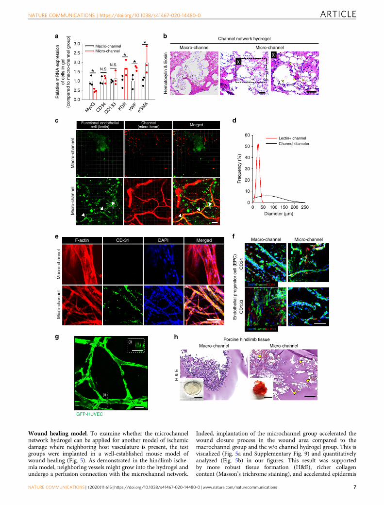
Wound healing model. To examine whether the microchannelnetwork hydrogel can be applied for another model of ischemicdamage where neighboring host vasculature is present, the testgroups were implanted in a well-established mouse model ofwound healing (Fig. 5). As demonstrated in the hindlimb ische-mia model, neighboring vessels might grow into the hydrogel andundergo a perfusion connection with the microchannel network.
Indeed, implantation of the microchannel group accelerated thewound closure process in the wound area compared to themacrochannel group and the w/o channel hydrogel group. This isvisualized (Fig. 5a and Supplementary Fig. 9) and quantitativelyanalyzed (Fig. 5b) in our figures. This result was supportedby more robust tissue formation (H&E), richer collagencontent (Masson’s trichrome staining), and accelerated epidermis
3.0Macro-channel Macro-channel
60Lectin+ channelChannel diameter
50
40
30
20
10
00 50 100 150
Diameter (μm)200 250
Mac
ro-c
hann
el
Freq
uenc
y (%
)
Mic
ro-c
hann
el
Mic
ro-c
hann
el
Micro-channelMacro-channel
Micro-channelMacro-channel
GFP-HUVEC
H &
E
Porcine hindlimb tissue
DAPI/F-actin/CD133
DAPI/F-actin/CD34
CD
34C
D13
3
End
othe
lial p
roge
nito
r ce
ll (E
PC
)
Mac
ro-c
hann
el
Micro-channel
(i)
(i)
Functional endothelialcell (lectin)
Channel(micro-bead) Merged
MergedDAPICD-31
(i)
(i)
F-actin
Channel network hydrogelba
c d
e
g h
f
Micro-channel
N.S.N.S.
Rel
ativ
e m
RN
A e
xpre
ssio
nof
cel
ls in
gel
(com
pare
d to
mac
ro-c
hann
el g
roup
)
2.5
2.0
1.5
1.0
0.5 Hem
atox
ylin
& E
osin
0.0
Myo
GCD34
CD133
KDRvW
FαSM
A
NATURE COMMUNICATIONS | https://doi.org/10.1038/s41467-020-14480-0 ARTICLE
NATURE COMMUNICATIONS | (2020) 11:615 | https://doi.org/10.1038/s41467-020-14480-0 | www.nature.com/naturecommunications 7
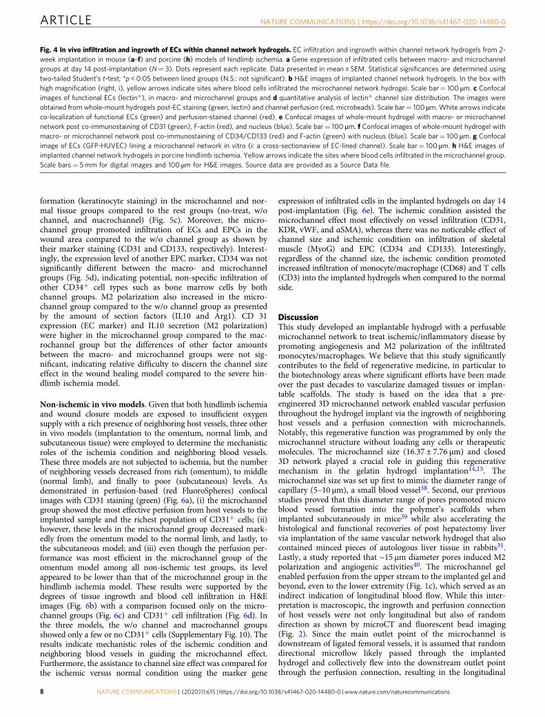
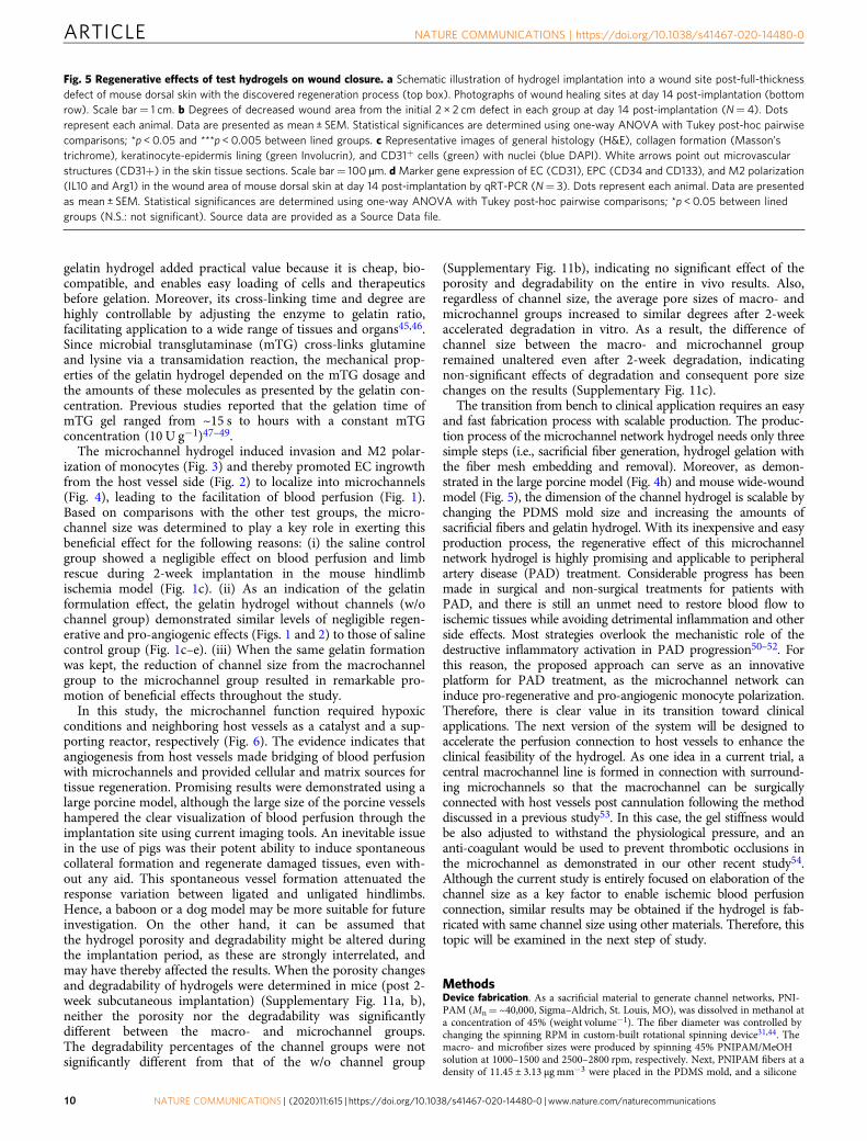
formation (keratinocyte staining) in the microchannel and nor-mal tissue groups compared to the rest groups (no-treat, w/ochannel, and macrochannel) (Fig. 5c). Moreover, the micro-channel group promoted infiltration of ECs and EPCs in thewound area compared to the w/o channel group as shown bytheir marker staining (CD31 and CD133, respectively). Interest-ingly, the expression level of another EPC marker, CD34 was notsignificantly different between the macro- and microchannelgroups (Fig. 5d), indicating potential, non-specific infiltration ofother CD34+ cell types such as bone marrow cells by bothchannel groups. M2 polarization also increased in the micro-channel group compared to the w/o channel group as presentedby the amount of section factors (IL10 and Arg1). CD 31expression (EC marker) and IL10 secretion (M2 polarization)were higher in the microchannel group compared to the mac-rochannel group but the differences of other factor amountsbetween the macro- and microchannel groups were not sig-nificant, indicating relative difficulty to discern the channel sizeeffect in the wound healing model compared to the severe hin-dlimb ischemia model.
Non-ischemic in vivo models. Given that both hindlimb ischemiaand wound closure models are exposed to insufficient oxygensupply with a rich presence of neighboring host vessels, three otherin vivo models (implantation to the omentum, normal limb, andsubcutaneous tissue) were employed to determine the mechanisticroles of the ischemia condition and neighboring blood vessels.These three models are not subjected to ischemia, but the numberof neighboring vessels decreased from rich (omentum), to middle(normal limb), and finally to poor (subcutaneous) levels. Asdemonstrated in perfusion-based (red FluoroSpheres) confocalimages with CD31 staining (green) (Fig. 6a), (i) the microchannelgroup showed the most effective perfusion from host vessels to theimplanted sample and the richest population of CD31+ cells; (ii)however, these levels in the microchannel group decreased mark-edly from the omentum model to the normal limb, and lastly, tothe subcutaneous model; and (iii) even though the perfusion per-formance was most efficient in the microchannel group of theomentum model among all non-ischemic test groups, its levelappeared to be lower than that of the microchannel group in thehindlimb ischemia model. These results were supported by thedegrees of tissue ingrowth and blood cell infiltration in H&Eimages (Fig. 6b) with a comparison focused only on the micro-channel groups (Fig. 6c) and CD31+ cell infiltration (Fig. 6d). Inthe three models, the w/o channel and macrochannel groupsshowed only a few or no CD31+ cells (Supplementary Fig. 10). Theresults indicate mechanistic roles of the ischemic condition andneighboring blood vessels in guiding the microchannel effect.Furthermore, the assistance to channel size effect was compared forthe ischemic versus normal condition using the marker gene
expression of infiltrated cells in the implanted hydrogels on day 14post-implantation (Fig. 6e). The ischemic condition assisted themicrochannel effect most effectively on vessel infiltration (CD31,KDR, vWF, and αSMA), whereas there was no noticeable effect ofchannel size and ischemic condition on infiltration of skeletalmuscle (MyoG) and EPC (CD34 and CD133). Interestingly,regardless of the channel size, the ischemic condition promotedincreased infiltration of monocyte/macrophage (CD68) and T cells(CD3) into the implanted hydrogels when compared to the normalside.
DiscussionThis study developed an implantable hydrogel with a perfusablemicrochannel network to treat ischemic/inflammatory disease bypromoting angiogenesis and M2 polarization of the infiltratedmonocytes/macrophages. We believe that this study significantlycontributes to the field of regenerative medicine, in particular tothe biotechnology areas where significant efforts have been madeover the past decades to vascularize damaged tissues or implan-table scaffolds. The study is based on the idea that a pre-engineered 3D microchannel network enabled vascular perfusionthroughout the hydrogel implant via the ingrowth of neighboringhost vessels and a perfusion connection with microchannels.Notably, this regenerative function was programmed by only themicrochannel structure without loading any cells or therapeuticmolecules. The microchannel size (16.37 ± 7.76 µm) and closed3D network played a crucial role in guiding this regenerativemechanism in the gelatin hydrogel implantation14,15. Themicrochannel size was set up first to mimic the diameter range ofcapillary (5–10 µm), a small blood vessel38. Second, our previousstudies proved that this diameter range of pores promoted microblood vessel formation into the polymer’s scaffolds whenimplanted subcutaneously in mice39 while also accelerating thehistological and functional recoveries of post hepatectomy livervia implantation of the same vascular network hydrogel that alsocontained minced pieces of autologous liver tissue in rabbits31.Lastly, a study reported that ~15 µm diameter pores induced M2polarization and angiogenic activities40. The microchannel gelenabled perfusion from the upper stream to the implanted gel andbeyond, even to the lower extremity (Fig. 1c), which served as anindirect indication of longitudinal blood flow. While this inter-pretation is macroscopic, the ingrowth and perfusion connectionof host vessels were not only longitudinal but also of randomdirection as shown by microCT and fluorescent bead imaging(Fig. 2). Since the main outlet point of the microchannel isdownstream of ligated femoral vessels, it is assumed that randomdirectional microflow likely passed through the implantedhydrogel and collectively flew into the downstream outlet pointthrough the perfusion connection, resulting in the longitudinal
Fig. 4 In vivo infiltration and ingrowth of ECs within channel network hydrogels. EC infiltration and ingrowth within channel network hydrogels from 2-week implantation in mouse (a–f) and porcine (h) models of hindlimb ischemia. a Gene expression of infiltrated cells between macro- and microchannelgroups at day 14 post-implantation (N= 3). Dots represent each replicate. Data presented in mean ± SEM. Statistical significances are determined usingtwo-tailed Student’s t-test; *p < 0.05 between lined groups (N.S.: not significant). b H&E images of implanted channel network hydrogels. In the box withhigh magnification (right, i), yellow arrows indicate sites where blood cells infiltrated the microchannel network hydrogel. Scale bar= 100 µm. c Confocalimages of functional ECs (lectin+), in macro- and microchannel groups and d quantitative analysis of lectin+ channel size distribution. The images wereobtained from whole-mount hydrogels post-EC staining (green, lectin) and channel perfusion (red, microbeads). Scale bar= 100 µm.White arrows indicateco-localization of functional ECs (green) and perfusion-stained channel (red). e Confocal images of whole-mount hydrogel with macro- or microchannelnetwork post co-immunostaining of CD31 (green), F-actin (red), and nucleus (blue). Scale bar= 100 µm. f Confocal images of whole-mount hydrogel withmacro- or microchannel network post co-immunostaining of CD34/CD133 (red) and F-actin (green) with nucleus (blue). Scale bar= 100 µm. g Confocalimage of ECs (GFP-HUVEC) lining a microchannel network in vitro (i: a cross-sectionaview of EC-lined channel). Scale bar= 100 µm. h H&E images ofimplanted channel network hydrogels in porcine hindlimb ischemia. Yellow arrows indicate the sites where blood cells infiltrated in the microchannel group.Scale bars= 5mm for digital images and 100 µm for H&E images. Source data are provided as a Source Data file.
ARTICLE NATURE COMMUNICATIONS | https://doi.org/10.1038/s41467-020-14480-0
8 NATURE COMMUNICATIONS | (2020) 11:615 | https://doi.org/10.1038/s41467-020-14480-0 | www.nature.com/naturecommunications

flow direction observed under the macroscopic doppler imaging(Fig. 1c).
The idea to generate a 3D-interconnected structure of sacrifi-cial fibers originated from the cotton candy machine, becauseelectrospinning did not work in depositing the volumetric fiber
mesh, and 3D printing was not able to reach sufficient resolutionfor producing the closed network of dense fibers41,42. Only acotton candy machine-like production of sacrificial fibers enablednutrient diffusion limits to be overcome, which was a game-changer in this approach43,44. The use of enzyme cross-linkable
ba
Wound
Channel network hydrogelWound regeneration
Micro-vessel anastomosis
Micro-channelnetwork
w/o channel Channel network hydrogel
Hydrogel implantation
No treat
Micro-channelMacro-channel0.0
No tre
at w/o
chan
nel
Mac
ro-
chan
nel
Micr
o-
chan
nel
w/o ch
anne
l
Mac
ro-
chan
nelM
icro-
chan
nel
w/o ch
anne
l
Mac
ro-
chan
nelM
icro-
chan
nel
w/o ch
anne
l
Mac
ro-
chan
nelM
icro-
chan
nel
w/o ch
anne
l
Mac
ro-
chan
nelM
icro-
chan
nel
w/o ch
anne
l
Mac
ro-
chan
nelM
icro-
chan
nel
0.5
1.0
1.5
2.0
Wou
nd a
rea
(cm
2 )
Channel network hydrogel
Channel networkhydrogel
Channel networkhydrogel
Channel networkhydrogel
Channel networkhydrogel
Channel networkhydrogel
****
*C
D 3
1
3.5
Endothelial cell EPC
CD31 CD34 CD133 IL10 Arg1
N.S. N.S.N.S.
N.S.
N.S.
N.S.
N.S.
N.S.
Rel
ativ
e m
RN
A e
xpre
ssio
n(c
ompa
red
to w
/o c
hann
el g
roup
)
2.5
2.0
1.5
1.0
0.5
0.0
2.0
1.5
1.0
0.5
0.0
2.0
2.5 7 12
10
8
6
4
2
0
6
5
4
3
2
1
0
1.5
1.0
0.5
0.0
3.0
w/o channelMicro-channel
Channel network hydrogelNo treatNormal tissue
H&
E
Involucrin/DAPI
CD 31/DAPI
c
d
Hydrogel
Hydrogel
Hydrogel
HydrogelHydrogel
Hydrogel implantation
Macro-channel
Epi
derm
is(k
erat
inoc
yte)
Col
lage
n(M
asso
n’s
tric
hrom
e)
M2 polarization
NATURE COMMUNICATIONS | https://doi.org/10.1038/s41467-020-14480-0 ARTICLE
NATURE COMMUNICATIONS | (2020) 11:615 | https://doi.org/10.1038/s41467-020-14480-0 | www.nature.com/naturecommunications 9
gelatin hydrogel added practical value because it is cheap, bio-compatible, and enables easy loading of cells and therapeuticsbefore gelation. Moreover, its cross-linking time and degree arehighly controllable by adjusting the enzyme to gelatin ratio,facilitating application to a wide range of tissues and organs45,46.Since microbial transglutaminase (mTG) cross-links glutamineand lysine via a transamidation reaction, the mechanical prop-erties of the gelatin hydrogel depended on the mTG dosage andthe amounts of these molecules as presented by the gelatin con-centration. Previous studies reported that the gelation time ofmTG gel ranged from ~15 s to hours with a constant mTGconcentration (10 U g−1)47–49.
The microchannel hydrogel induced invasion and M2 polar-ization of monocytes (Fig. 3) and thereby promoted EC ingrowthfrom the host vessel side (Fig. 2) to localize into microchannels(Fig. 4), leading to the facilitation of blood perfusion (Fig. 1).Based on comparisons with the other test groups, the micro-channel size was determined to play a key role in exerting thisbeneficial effect for the following reasons: (i) the saline controlgroup showed a negligible effect on blood perfusion and limbrescue during 2-week implantation in the mouse hindlimbischemia model (Fig. 1c). (ii) As an indication of the gelatinformulation effect, the gelatin hydrogel without channels (w/ochannel group) demonstrated similar levels of negligible regen-erative and pro-angiogenic effects (Figs. 1 and 2) to those of salinecontrol group (Fig. 1c–e). (iii) When the same gelatin formationwas kept, the reduction of channel size from the macrochannelgroup to the microchannel group resulted in remarkable pro-motion of beneficial effects throughout the study.
In this study, the microchannel function required hypoxicconditions and neighboring host vessels as a catalyst and a sup-porting reactor, respectively (Fig. 6). The evidence indicates thatangiogenesis from host vessels made bridging of blood perfusionwith microchannels and provided cellular and matrix sources fortissue regeneration. Promising results were demonstrated using alarge porcine model, although the large size of the porcine vesselshampered the clear visualization of blood perfusion through theimplantation site using current imaging tools. An inevitable issuein the use of pigs was their potent ability to induce spontaneouscollateral formation and regenerate damaged tissues, even with-out any aid. This spontaneous vessel formation attenuated theresponse variation between ligated and unligated hindlimbs.Hence, a baboon or a dog model may be more suitable for futureinvestigation. On the other hand, it can be assumed thatthe hydrogel porosity and degradability might be altered duringthe implantation period, as these are strongly interrelated, andmay have thereby affected the results. When the porosity changesand degradability of hydrogels were determined in mice (post 2-week subcutaneous implantation) (Supplementary Fig. 11a, b),neither the porosity nor the degradability was significantlydifferent between the macro- and microchannel groups.The degradability percentages of the channel groups were notsignificantly different from that of the w/o channel group
(Supplementary Fig. 11b), indicating no significant effect of theporosity and degradability on the entire in vivo results. Also,regardless of channel size, the average pore sizes of macro- andmicrochannel groups increased to similar degrees after 2-weekaccelerated degradation in vitro. As a result, the difference ofchannel size between the macro- and microchannel groupremained unaltered even after 2-week degradation, indicatingnon-significant effects of degradation and consequent pore sizechanges on the results (Supplementary Fig. 11c).
The transition from bench to clinical application requires an easyand fast fabrication process with scalable production. The produc-tion process of the microchannel network hydrogel needs only threesimple steps (i.e., sacrificial fiber generation, hydrogel gelation withthe fiber mesh embedding and removal). Moreover, as demon-strated in the large porcine model (Fig. 4h) and mouse wide-woundmodel (Fig. 5), the dimension of the channel hydrogel is scalable bychanging the PDMS mold size and increasing the amounts ofsacrificial fibers and gelatin hydrogel. With its inexpensive and easyproduction process, the regenerative effect of this microchannelnetwork hydrogel is highly promising and applicable to peripheralartery disease (PAD) treatment. Considerable progress has beenmade in surgical and non-surgical treatments for patients withPAD, and there is still an unmet need to restore blood flow toischemic tissues while avoiding detrimental inflammation and otherside effects. Most strategies overlook the mechanistic role of thedestructive inflammatory activation in PAD progression50–52. Forthis reason, the proposed approach can serve as an innovativeplatform for PAD treatment, as the microchannel network caninduce pro-regenerative and pro-angiogenic monocyte polarization.Therefore, there is clear value in its transition toward clinicalapplications. The next version of the system will be designed toaccelerate the perfusion connection to host vessels to enhance theclinical feasibility of the hydrogel. As one idea in a current trial, acentral macrochannel line is formed in connection with surround-ing microchannels so that the macrochannel can be surgicallyconnected with host vessels post cannulation following the methoddiscussed in a previous study53. In this case, the gel stiffness wouldbe also adjusted to withstand the physiological pressure, and ananti-coagulant would be used to prevent thrombotic occlusions inthe microchannel as demonstrated in our other recent study54.Although the current study is entirely focused on elaboration of thechannel size as a key factor to enable ischemic blood perfusionconnection, similar results may be obtained if the hydrogel is fab-ricated with same channel size using other materials. Therefore, thistopic will be examined in the next step of study.
MethodsDevice fabrication. As a sacrificial material to generate channel networks, PNI-PAM (Mn= ~40,000, Sigma–Aldrich, St. Louis, MO), was dissolved in methanol ata concentration of 45% (weight volume−1). The fiber diameter was controlled bychanging the spinning RPM in custom-built rotational spinning device31,44. Themacro- and microfiber sizes were produced by spinning 45% PNIPAM/MeOHsolution at 1000–1500 and 2500–2800 rpm, respectively. Next, PNIPAM fibers at adensity of 11.45 ± 3.13 μg mm−3 were placed in the PDMS mold, and a silicone
Fig. 5 Regenerative effects of test hydrogels on wound closure. a Schematic illustration of hydrogel implantation into a wound site post-full-thicknessdefect of mouse dorsal skin with the discovered regeneration process (top box). Photographs of wound healing sites at day 14 post-implantation (bottomrow). Scale bar= 1 cm. b Degrees of decreased wound area from the initial 2 × 2 cm defect in each group at day 14 post-implantation (N= 4). Dotsrepresent each animal. Data are presented as mean ± SEM. Statistical significances are determined using one-way ANOVA with Tukey post-hoc pairwisecomparisons; *p < 0.05 and ***p < 0.005 between lined groups. c Representative images of general histology (H&E), collagen formation (Masson’strichrome), keratinocyte-epidermis lining (green Involucrin), and CD31+ cells (green) with nuclei (blue DAPI). White arrows point out microvascularstructures (CD31+) in the skin tissue sections. Scale bar= 100 µm. d Marker gene expression of EC (CD31), EPC (CD34 and CD133), and M2 polarization(IL10 and Arg1) in the wound area of mouse dorsal skin at day 14 post-implantation by qRT-PCR (N= 3). Dots represent each animal. Data are presentedas mean ± SEM. Statistical significances are determined using one-way ANOVA with Tukey post-hoc pairwise comparisons; *p < 0.05 between linedgroups (N.S.: not significant). Source data are provided as a Source Data file.
ARTICLE NATURE COMMUNICATIONS | https://doi.org/10.1038/s41467-020-14480-0
10 NATURE COMMUNICATIONS | (2020) 11:615 | https://doi.org/10.1038/s41467-020-14480-0 | www.nature.com/naturecommunications

tube was placed to connect with the fibers at the inlet and outlet sides so that flowcould be perfused through the inlet silicone tube to the fiber-generated channelnetwork and to the outlet silicone tube. Then, a gelatin/mTG solution (9:1 ratio,final concentration= 5% weight volume−1) was poured onto it, followed by across-linking reaction with mTG at 37 °C. The embedded fibers were dissolvedaway from the mTG hydrogel by sol–gel transition of PNIPAM at room tem-perature with perfusing PBS in connection with the silicone tube (SupplementaryFigs. 1a and 3). As a result, a 3D micro- or macrochannel network was formed inthe gelatin hydrogel. The channel networks were visualized by perfusing redFluoroSpheres (45 nm, Invitrogen) and then imaged by confocal microscopy (LSM780, Zeiss). The channel size distribution of the macro- and microchannels in thehydrogel was quantified using ImageJ/Fiji software. The channel network of testgelatin hydrogel was perfused with culture media containing FITC-dextran
(molecular weight= 40,000, Sigma-Aldrich, MO) and red FluoroSpheres (45 nm,Invitrogen) throughout the channel network of test hydrogel at 20 μmmin−1 for30 min, followed by confocal imaging (LSM 780, Zeiss) to determine its diffusivityand perfusability, respectively.
Mouse and porcine models of hindlimb ischemia. All procedures of mouse andporcine studies were approved by the Institutional Animal Care and Use Com-mittee (IACUC) of Yonsei University College of Medicine (2016-0194 and 2017-0058 for mouse and porcine, respectively). For the mouse model, 5-week-old Balb/cmale mice (Orient bio., Republic of Korea) with a weight range of 20–25 g weresubject to anesthesia by intraperitoneal injection of xylazine (10 mg kg−1) andzoletil (50 mg kg−1). In their left limbs, the upper and lower points of femoral
Hydrogel Hydrogel
Hydrogel
ba
e
w/o channel
Gre
ater
omen
tum
Gre
ater
om
entu
m (
GO
)
Nor
mal
hind
limb
Nor
mal
hin
dlim
b
Sub
cuta
neou
s
Sub
cuta
neou
sChannel network hydrogel
Macro-channel Micro-channel
c Greater omentum Normal hindlimb Subcutaneous
Mic
ro-c
hann
el
Hydrogel
Hydrogel
HydrogelHydrogel
SurfaceSurfaceSurfacey
xy
x
zx
yx
zx
zx
yx
yx
zx
yx
zx
zx
yx
yx
zx
yx
zx
zx
HydrogelHydrogel
Hydrogel
SurfaceSurfaceSurface
HydrogelHydrogel
Hydrogel
SurfaceSurfaceSurface
Hydrogel
Rel
ativ
e m
RN
A e
xpre
ssio
nof
cel
ls in
hyd
roge
l(c
ompa
red
to h
ydro
gel
in n
on-is
chem
ic ti
ssue
)
Rel
ativ
e m
RN
A e
xpre
ssio
nof
cel
ls in
hyd
roge
l(c
ompa
red
to h
ydro
gel
in n
on-is
chem
ic ti
ssue
)
6 12
10
8
6
4
2
0
12
10
3.0
2.5
2.0
1.5
1.0
0.5
0.0
3.0 5
4
3
2
1
0
2.5
2.0
1.5
1.0
0.5
0.0
8
6
4
2
0
121416 2.0
1.5
1.0
0.5
0.0
1086420
CD31 KDR vWF αSMA
5
4
3
2 N.S.
N.S.
N.S.
N.S.N.S. N.S.
N.S.
N.S.
N.S.
N.S.
N.S.
N.S.
1
0
5
CD68 CD3 CD34 CD133 MyoG
4
3
2
1
0
Macro-channel
Micro-channel
Hydrogel
Channel networkhydrogel
Mousehindlimb tissue
Non-ischemia
Non-ischemiaIschemia
Non-ischemiaIschemia
Non-ischemiaIschemia Non-ischemia
IschemiaNon-ischemiaIschemia
Non-ischemiaIschemia
Non-ischemiaIschemia
Non-ischemiaIschemia
Non-ischemiaIschemia
Ischemia
Microbead/CD31/DAPI
Hydrogel
Hydrogel
Hydrogel
Hydrogel
Hydrogel
Hydrogel
Hydrogel
Hydrogel
Hydrogel
CD31 / DAPI
dM
icro
-cha
nnel
Greater omentum Normal hindlimb Subcutaneous
Section staining
w/o channel
Channel network hydrogel
Macro-channel Micro-channel
Whole-mount staining
Macro-channel
Micro-channel
Macro-channel
Micro-channel
Macro-channel
Micro-channel
Macro-channel
Micro-channel
Macro-channel
Micro-channel
Macro-channel
Micro-channel
Macro-channel
Micro-channel
Macro-channel
Micro-channel
NATURE COMMUNICATIONS | https://doi.org/10.1038/s41467-020-14480-0 ARTICLE
NATURE COMMUNICATIONS | (2020) 11:615 | https://doi.org/10.1038/s41467-020-14480-0 | www.nature.com/naturecommunications 11

artery and vein were ligated using a 6-0 silk suture (Ethicon, Somerville, NJ)32
(Supplementary Fig. 5a), followed by resection of vessels between the two points.The ligation points were the proximal branch point of the external iliac artery andthe distal point where it bifurcates into the saphenous and popliteal arteries. A testgroup hydrogel (4 mm × 4mm× 3mm) was implanted into the center hindlimbmuscle of the ischemic vessel-resected area in a post-surgery mouse (Figs. 1–4) orthe same muscle position of the non-ischemic hindlimb in a normal mouse (Fig. 6)to comparatively determine the ischemic effect until euthanized in 14 days. Asanother ischemia model in mice, a full thickness defect was induced on the dorsalskin of a mouse (Fig. 5). Then, a test group hydrogel (2 cm × 2 cm × 3 mm) wasplaced to cover the defect site by sealing with dressing film (TegadermTM, 3MMedical) for 14 days. As non-ischemic models, greater omentum and subcutaneoustissue with 14-day hydrogel implantation served as host neighboring vessel-richand vessel-poor models, respectively, to determine the mechanistic role of thenumber of host vessels in angiogenesis-mediated perfusion connection withchannel networks. Four mice were grouped to each wire-mesh cage ((W) 200 × (D)260 × (H) 130 mm) and housed in a temperature (22 ± 2 °C) and humidity (50 ±10%) regulated environment with a 12-h light–dark cycle.
For a porcine model of hindlimb ischemia, 3-month-old female Yorkshire pigs(XP Bio, Republic of Korea) of 40 kg were subject to intramuscular injection ofatropine (0.04 mg kg−1), xylazine (2 mg kg−1), and azaperone (2 mg kg−1) aspremedication. Anesthesia was then induced with Alfaxan (1 mg kg−1) and wasmaintained by endotracheal intubation of 2% isoflurane during surgery. As withthe mouse model of hindlimb ischemia, the femoral artery and veins were ligatedwith 1-0 silk and dissected. Test group hydrogels (cylinder shape: 1 cm in diameterand 1.5 cm in height) were implanted into the central hindlimb muscle of theischemic area until euthanized in 18 days for histological examination (H&E).
Because discrimination between the inside and outside of the hydrogel is onlypossible using histology, histological analysis was conducted on the hydrogeltogether with connected tissues immediately after harvesting. The hydrogel partwas carefully dissociated from the connected tissue part, and the two parts wereused separately to conduct quantitative PCR because positional discrimination wasnot possible using quantitative PCR (Supplementary Table 1).
In vivo and in vitro degradability and porosity measurement. The in vivodegradability of the gelatin hydrogel groups (i.e., w/o channel, macrochannel, andmicrochannel in 1 cm diameter with 2 mm thickness) was determined by sub-cutaneously implanting into mice for 2 weeks (N= 4). Each test sample was thenharvested, rinsed with PBS three times, and lyophilized to measure its dry weight.The mass loss as an indication of degradation degree was calculated by comparingto the corresponding dry weight before implantation (%). At the same time, theporosity of macro- or microchannel hydrogels was determined by calculating therelative dry weight to that of w/o channel hydrogel (%) post 2-week subcutaneousimplantation in mice. Sample degradation was accelerated in vitro by immersing inPBS with stirring at 37 °C for 2 weeks. Samples were freeze-dried for 24 h andhorizontally sectioned. The pore sizes of test groups were observed by field emis-sion scanning electron microscopy (FE-SEM; MERLIN, Zeiss, Oberkochen, Baden-Württemberg, Germany), followed by quantitative analysis of the pore size usingImageJ/Fiji software.
Laser Doppler imaging. Blood perfusion into the implant areas was determined atdays 0, 7, and 14 post surgery by LDPI (Moor Instruments, Devon, UK) withquantitative analysis of LDPI values. The mouse body temperature was maintainedby keeping it on a heating pad during LDPI scanning to minimize perfusionvariations. The highest and lowest values of perfusion (LDPI) were color-coded tored and dark blue, respectively. The relative perfusion ratio was calculated bydividing the mean perfusion value of the ischemic hindlimb (left) by that of thenormal hindlimb (right) from the corresponding LDPI image. Degrees of limb loss
were determined following the reported amputation criteria in previousstudies55,56. Tissue damage in the ischemic limb (limb salvage score) was graded asfull recovery (grade 6), minor necrosis or nail loss (grade 5), partial toe amputation(grade 4), total toe amputation (grade 3), partial/total foot amputation (grade 2), orpartial/total limb amputation (grade 1). Following these criteria, the damage degreeof ischemic hindlimb tissue was quantitatively determined and presented as a limbsalvage % among the ranges of limb rescue (recovery), toe loss, foot loss, and limbloss (amputation). Although the biological N (animal number) was 5, the degree ofhindlimb ischemia salvage was scored by three blinded evaluators, and thus, thetechnical N was 11–14.
MicroCT angiography. Blood perfusion from host blood vessels to each implantedhydrogel was determined by microCT angiography. After anesthetizing with iso-flurane, the mice were subject to a tail vein injection of Pamiray 370 (100 µL ofiopamidol-370, Dongkook CO., LTD, Republic of Korea) as a contrast agent andthen to microCT scanning (NFR Polaris-G90, Nano Focus Ray, Korea) following astandard protocol (tube voltage: 65 Kvp; tube current: 115 µA; 720 views per 360°rotation; resolution: 100 μm). The acquired microCT images were reconstructedusing the volumetric cone-beam reconstruction (FDK) algorithm, and analyzedusing a 3D-rendering software (RadiAnt DICOM Viewer 4.2.1).
In vivo EC infiltration and host vessel ingrowth. EC infiltration from thedistal site of the ischemic hindlimb to the implanted hydrogels was determinedby confocal imaging post tail vein injection of lectin (100 μL, FITC-conjugated,L-2895, Sigma–Aldrich) for 30 min. Flow perfusion connection from neighboringvessels to channel networks was imaged according to a previously reportedmethod57,58. Briefly, after cutting the inferior vena cava of the mouse, PBS con-taining 0.1 mg mL−1 heparin sulfate was perfused through the left ventricle toremove whole blood through the cut drain point. PBS containing red fluorescentmicrobeads (45 nm in diameter, Invitrogen) was then perfused through the leftventricle for fluorescence visualization of perfusable vessels and channels, followedby sample harvest and fixation with 3.7% formaldehyde. Z-stacks of each whole-mount sample (gel with neighboring tissue) was subject to confocal imaging (LSM780, Zeiss), followed by quantitative analysis of functional vasculature parameters(i.e. total branching length, branch number, junction number, and blood vesselfractional area per field of view) using ImageJ/Fiji software.
Tissue and cell staining. The harvested samples were rinsed with PBS three timesand then fixed with 10% weight volume−1 paraformaldehyde for 1 day, followed byembedding in paraffin to make sections. Sections of 4 µm thickness were obtainedfrom six different locations of each block by microtome slicing, then subjected tostaining with H&E and Masson’s trichrome for analysis of general histology andtissue fibrosis, respectively, by inverted microscopy (Leica DMi8, Leica Micro-systems, Wetzlar, Germany).
The same sections were reused for immunofluorescence staining, and thus,hydrated by serial incubation in xylene and ethanol (100%, 95%, 80%, and 70%volume volume−1 in distilled water), followed by treatment with pepsin reagent(Sigma–Aldrich) for 30 min at 37 °C to retrieve antigens. The whole-mount samplewas subject to blocking with a buffer solution of 5% weight volume−1 bovine serumalbumin (Millipore) and 0.3% (weight volume−1) Triton X-100 (Sigma–Aldrich)for 1 h at room temperature. The sample blocks were then incubated with primaryantibodies (1:100 dilution) for CD68 (ab125212, Abcam), CD31 (sc-1505, SantaCruz Biotechnology), Involucrin (sc-21748, Santa Cruz), F4/80 (ab6640, Abcam),iNOS (ab955, Abcam), and CD206 (ab64693, Abcam) overnight at 4 °C, followedby incubation with Alexa Fluor 488 or Alexa Fluor 594-conjugated secondaryantibodies (1:100 dilution) (Jackson Immuno Research Laboratories, West Grove,PA, USA). The sample blocks were counterstained with DAPI (H-1500, Vector
Fig. 6 Vascularization efficiencies of microchannel hydrogel implantation in non-ischemic mouse models. The number of surrounding host vesselsdecreases from the greater omentum to normal hindlimb, and lastly, to the subcutaneous site. a Confocal images of whole-mount hydrogels post perfusionof blood vessels (red fluorescence microbeads) with immunostaining of CD31+ cells (green) and nucleus (blue DAPI) at day 14 post-implantation. Theimages were three-dimensionally reconstructed to determine vascular ingrowth and perfusion connection through red FluoroSphere perfusion from hostvessels into the channel network. Scale bar= 100 µm. b Representative H&E images of test groups. The box areas (100×) were magnified to c (200×).Scale bar= 100 µm. c High magnification (200×) H&E images from black-dotted boxes of micro-channel group in b. Blue arrows indicate the points whereblood cells infiltrated into the implanted hydrogel or surrounding tissue of the greater omentum, normal hindlimb, and subcutaneous site (no blood cellinfiltration). Scale bar= 100 µm. d Confocal images of CD31+ cells (green) in the sectioned tissues of each model containing a part of microchannelnetwork hydrogel (blue: nucleus with DAPI staining). Scale bar= 100 µm. e Effects of channel size on cell infiltration into the normal side versus theischemic hindlimb side, as presented by marker gene expression of the vessel (CD31, KDR, vWF, and αSMA), skeletal muscle (MyoG), monocyte/macrophage (CD68), T cell (CD3), and EPC (CD34 and CD133) cells in macro- and microchannel network hydrogels. qRT-PCR was conducted using onlygel samples after removing the surrounding tissues on day 14 post-implantation (N= 4). Dots represent hydrogel sample in each animal. Data arepresented mean ± SEM. Statistical significances are determined using two-tailed Student’s t-test; *p < 0.05, **p < 0.01, and ***p < 0.005 between linedgroups (N.S.: not significant). Source data are provided as a Source Data file.
ARTICLE NATURE COMMUNICATIONS | https://doi.org/10.1038/s41467-020-14480-0
12 NATURE COMMUNICATIONS | (2020) 11:615 | https://doi.org/10.1038/s41467-020-14480-0 | www.nature.com/naturecommunications

Laboratories) and imaged by confocal microscopy (LSM 780, Zeiss) withquantitative analysis using ImageJ/Fiji software.
Cell apoptosis in samples was determined by TUNEL staining (RocheMolecular Biochemicals, Mannheim, Germany) according to the manufacturer’sprotocol, followed by confocal imaging (LSM 780, Zeiss) with quantitative analysisusing the ImageJ/Fiji software.
For whole-mount staining of the hydrogel, hydrogel samples were rinsed withPBS three times and then fixed with 10% paraformaldehyde for 1 day. The hydrogelsamples were rinsed with PBS again and treated with primary antibodies (1:100dilution) for CD31 (sc-1505, Santa Cruz Biotechnology, Dallas, Texas), CD34(ab81289, Abcam, Cambridge, MA), CD133 (ab19898, Abcam) overnight at 4 °C,followed by treatment with Alexa Fluor 488 or Alexa Fluor 594-conjugatedsecondary antibodies (1:100 dilution; Jackson Immuno Research Laboratories,West Grove, PA). Cell nuclei were counterstained with DAPI (4′,6-diamidino-2-phenylindole; H-1500, Vector Laboratories) and imaged via confocal microscopy(LSM 780, Zeiss).
Macrophage infiltration and polarization. In vivo monocyte infiltration toimplantation sites was determined by labeling mouse monocytes (RAW264.7) witha fluorescent dye (Vivotrack 680, PerkinElmer, MA) according to the manu-facturer’s instruction. These monocytes (2 × 10⁶ cells per mouse) were injectedintravenously at day 3 post hindlimb ischemia surgery (n= 4), and their bio-distribution was determined using an IVIS (PerkinElmer) at 24 h post injection.The Vivotrack intensity at the gel implantation site of ischemic hindlimb wasanalyzed in comparison with that of the normal hindlimb. Samples were harvestedpost mouse euthanasia and processed for other studies.
In vitro macrophage polarization was determined by culturing RAW264.7 cells(5 × 10⁵ cells) in channel hydrogels with media perfusion at 20 μLmin−1 byperistaltic pumping for 2 days. The samples were treated with LPS (100 ng mL−1)to induce inflammatory activation of RAW264.7 cells for 1 day and then subject toqRT-PCR analysis.
The effect of channel size on monocyte/macrophage polarization wasconfirmed by determining the migration and tubulogenesis of ECs undertreatment of conditioned media. The conditioned media was obtained from a 2-day culture of RAW264.7 cells (5 × 10⁵ cells) within each hydrogel with a mediaperfusion at 20 μL min−1 via peristaltic pumping. As a control condition for M1polarization, RAW264.7 cells were cultured under treatment of LPS (100 ng mL−1). For the tubulogenesis assay, human umbilical vein ECs (HUVECs, 2 × 10⁵
cells per well) were seeded onto matrigel (Corning, NY) in 24-well plates(ThermoFisher Scientific). For the migration assay, a PDMS disc (Dia.= 2 mmand thickness= 4 mm) was placed onto each of 24 wells, and the same number ofHUVECs were seeded into the well such that HUVECs could migrate into theblank area where the PDMS disc was removed. Endothelial growth media (EGM-2, Lonza, Basel, Switzerland) was treated for 2 h to allow HUVEC attachment,followed by replacement of the media with the conditioned media from each testgroup. Tubulogenesis of HUVECs was imaged at 8 h post treatment of theconditioned media and analyzed using an angiogenesis analyzer plug-in atImageJ/Fiji software. For the migration assay, PDMS disc was removedimmediately after treatment of the conditioned media, and HUVEC migrationinto the blank area was then imaged at 8, 16, and 24 h post treatment of theconditioned media, so that the HUVECs’ covering area could be quantitativelydetermined.
Quantitative RT-PCR analysis. Total RNA was prepared from implanted samplesusing TRIzol® reagent and was then treated with DNase, followed by reversetranscription with RNA (1 μg) and random-hexamer primers to generate cDNAusing a kit (TAKARA Bio Inc., Japan). Quantitative PCR was conducted withcDNA using SYBR® Green and primers (forward and reverse) in a StepOneTM
Real-Time PCR system (Applied Biosystems, Foster City, CA). The relative geneexpression level was determined by calculating the corresponding comparative Ct(2−ΔΔCt) value against that of glyceraldehyde 3-phosphate dehydrogenase(GAPDH) as a housekeeping gene. The primer sequences are listed in Supple-mentary Table 1.
Statistical analysis. Each experiment was repeated three times. All data are pre-sented as a mean ± SEM. All quantitative data were analyzed using a two-tailedStudent’s t-test or one-way analysis of variance (ANOVA) with Tukey’s significantdifference post-hoc test for multiple comparisons (SPSS 21.0K for Windows, SPSS,Chicago, IL, USA). Values of *p < 0.05, **p < 0.01, and ***p < 0.005 were consideredstatistically significant.
Reporting summary. Further information on research design is available inthe Nature Research Reporting Summary linked to this article.
Data availabilityThe source data underlying Figs. 1b, d, e, g, and h, 2d–g, 3a, b, and d–g, 4a, 5b and d, 6e,and Supplementary Fig. 11a–c are provided as a Source Data file. All other relevant dataare available upon request.
Received: 9 May 2019; Accepted: 12 January 2020;
References1. Martin, P. Wound healing–aiming for perfect skin regeneration. Science 276,
75–81 (1997).2. Griffith, L. G. & Naughton, G. Tissue engineering–current challenges and
expanding opportunities. Science 295, 1009–1014 (2002).3. Street, J. et al. Vascular endothelial growth factor stimulates bone repair by
promoting angiogenesis and bone turnover. Proc. Natl Acad. Sci. USA 99,9656–9661 (2002).
4. Brudno, Y., Ennett-Shepard, A. B., Chen, R. R., Aizenberg, M. & Mooney, D. J.Enhancing microvascular formation and vessel maturation through temporalcontrol over multiple pro-angiogenic and pro-maturation factors. Biomaterials34, 9201–9209 (2013).
5. Del Gaudio, C. et al. Induction of angiogenesis using VEGF releasing genipin-crosslinked electrospun gelatin mats. Biomaterials 34, 7754–7765 (2013).
6. Rivard, A. et al. Age-dependent impairment of angiogenesis. Circulation 99,111–120 (1999).
7. Bhise, N. S., Shmueli, R. B., Sunshine, J. C., Tzeng, S. Y. & Green, J. J. Drugdelivery strategies for therapeutic angiogenesis and antiangiogenesis. ExpertOpin. Drug Deliv. 8, 485–504 (2011).
8. Weaver, J. D. et al. Vasculogenic hydrogel enhances islet survival, engraftment,and function in leading extrahepatic sites. Sci. Adv. 3, e1700184 (2017).
9. Simons, M. Angiogenesis. Circulation 111, 1556–1566 (2005).10. Cho, B.-R. et al. p-Hydroxybenzyl alcohol-containing biodegradable
nanoparticle improves functional blood flow through angiogenesis in a mousemodel of hindlimb ischemia. Biomaterials 53, 679–687 (2015).
11. Van Hove, A. H. & Benoit, D. S. W. Depot-based delivery systems for pro-angiogenic peptides: a review. Front. Bioeng. Biotechnol. 3, 102 (2015).
12. Yamauchi, H., Cristofanilli, M., Nakamura, S., Hortobagyi, G. N. & Ueno, N.T. Molecular targets for treatment of inflammatory breast cancer. Nat. Rev.Clin. Oncol. 6, 387–394 (2009).
13. Sacchi, V. et al. Long-lasting fibrin matrices ensure stable and functionalangiogenesis by highly tunable, sustained delivery of recombinant VEGF164.Proc. Natl Acad. Sci. USA 111, 6952–6957 (2014).
14. Garg, K., Pullen, N. A., Oskeritzian, C. A., Ryan, J. J. & Bowlin, G. L.Macrophage functional polarization (M1/M2) in response to varying fiber andpore dimensions of electrospun scaffolds. Biomaterials 34, 4439–4451 (2013).
15. Madden, L. R. et al. Proangiogenic scaffolds as functional templates for cardiactissue engineering. Proc. Natl Acad. Sci. USA 107, 15211–15216 (2010).
16. Nguyen, D. H. et al. Biomimetic model to reconstitute angiogenic sproutingmorphogenesis in vitro. Proc. Natl Acad. Sci. USA 110, 6712–6717 (2013).
17. Zhang, B. et al. Biodegradable scaffold with built-in vasculature for organ-on-a-chip engineering and direct surgical anastomosis. Nat. Mater. 15, 669–678(2016).
18. Arakawa, C. K., Badeau, B. A., Zheng, Y. & DeForest, C. A. Multicellularvascularized engineered tissues through user-programmable biomaterialphotodegradation. Adv. Mater. 29, 1703156 (2017).
19. Polverini, P. J. The pathophysiology of angiogenesis. Crit. Rev. Oral Biol. Med.6, 230–247 (1995).
20. Felmeden, D. C., Blann, A. D. & Lip, G. Y. Angiogenesis: basic pathophysiologyand implications for disease. Eur. Heart J. 24, 586–603 (2003).
21. Isner, J. M. & Asahara, T. Angiogenesis and vasculogenesis as therapeuticstrategies for postnatal neovascularization. J. Clin. Invest. 103, 1231–1236(1999).
22. Hendrix, M. J. C., Seftor, E. A., Hess, A. R. & Seftor, R. E. B. Vasculogenicmimicry and tumour-cell plasticity: lessons from melanoma. Nat. Rev. Cancer3, 411 (2003).
23. Shweiki, D., Itin, A., Soffer, D. & Keshet, E. Vascular endothelial growth factorinduced by hypoxia may mediate hypoxia-initiated angiogenesis. Nature 359,843–845 (1992).
24. Jackson, J. R., Seed, M. P., Kircher, C. H., Willoughby, D. A. & Winkler, J. D.The codependence of angiogenesis and chronic inflammation. FASEB J. 11,457–465 (1997).
25. Kuehbacher, A., Urbich, C. & Dimmeler, S. Role of microRNAs in vasculardiseases, inflammation, and angiogenesis. Cardiovasc. Res. 79, 581–588 (2008).
26. Rehman, J., Li, J., Orschell, C. M. & March, K. L. Peripheral blood “endothelialprogenitor cells” are derived from monocyte/macrophages and secreteangiogenic growth factors. Circulation 107, 1164–1169 (2003).
27. Jetten, N. et al. Anti-inflammatory M2, but not pro-inflammatory M1macrophages promote angiogenesis in vivo. Angiogenesis 17, 109–118 (2014).
28. Mantovani, A., Sozzani, S., Locati, M., Allavena, P. & Sica, A. Macrophagepolarization: tumor-associated macrophages as a paradigm for polarized M2mononuclear phagocytes. Trends Immunol. 23, 549–555 (2002).
NATURE COMMUNICATIONS | https://doi.org/10.1038/s41467-020-14480-0 ARTICLE
NATURE COMMUNICATIONS | (2020) 11:615 | https://doi.org/10.1038/s41467-020-14480-0 | www.nature.com/naturecommunications 13

29. Martinez, F. O., Sica, A., Mantovani, A. & Locati, M. Macrophage activationand polarization. Front. Biosci. 13, 453–461 (2008).
30. Asahara, T. et al. Isolation of putative progenitor endothelial cells forangiogenesis. Science 275, 964–966 (1997).
31. Lee, J. B. et al. Implantable vascularized liver chip for cross-validation ofdisease treatment with animal model. Adv. Funct. Mater. 29, 1900075 (2019).
32. Limbourg, A. et al. Evaluation of postnatal arteriogenesis and angiogenesis in amouse model of hind-limb ischemia. Nat. Protoc. 4, 1737–1746 (2009).
33. Jain, R. K. Molecular regulation of vessel maturation. Nat. Med. 9, 685–693 (2003).34. Koike, N. et al. Creation of long-lasting blood vessels. Nature 428, 138–139 (2004).35. Griffith, T. M., Edwards, D. H., Davies, R. L., Harrison, T. J. & Evans, K. T.
EDRF coordinates the behaviour of vascular resistance vessels. Nature 329,442–445 (1987).
36. Greene, A. S., Tonellato, P. J., Lui, J., Lombard, J. H. & Cowley, A. W. Jr.Microvascular rarefaction and tissue vascular resistance in hypertension. Am.J. Physiol. 256, H126–H131 (1989).
37. Martinez, F. O. & Gordon, S. The M1 and M2 paradigm of macrophageactivation: time for reassessment. F1000Prime Rep. 6, 13 (2014).
38. Sakai, T. & Hosoyamada, Y. Are the precapillary sphincters and metarteriolesuniversal components of the microcirculation? An historical review. J. Physiol.Sci. 63, 319–331 (2013).
39. Sung, H. J., Meredith, C., Johnson, C. & Galis, Z. S. The effect of scaffolddegradation rate on three-dimensional cell growth and angiogenesis.Biomaterials 25, 5735–5742 (2004).
40. Garg, K., Pullen, N. A., Oskeritzian, C. A., Ryan, J. J. & Bowlin, G. L.Macrophage functional polarization (M1/M2) in response to varying fiber andpore dimensions of electrospun scaffolds. Biomaterials 34, 4439–4451 (2013).
41. Miller, J. S. et al. Rapid casting of patterned vascular networks for perfusableengineered three-dimensional tissues. Nat. Mater. 11, 768 (2012).
42. Kolesky, D. B., Homan, K. A., Skylar-Scott, M. A. & Lewis, J. A. Three-dimensional bioprinting of thick vascularized tissues. Proc. Natl Acad. Sci.USA 113, 3179–3184 (2016).
43. Bellan, L. M., Pearsall, M., Cropek, D. M. & Langer, R. A 3D interconnectedmicrochannel network formed in gelatin by sacrificial shellac microfibers. Adv.Mater. 24, 5187–5191 (2012).
44. Lee, J. B. et al. Development of 3D microvascular networks within gelatinhydrogels using thermoresponsive sacrificial microfibers. Adv. Healthc. Mater.5, 781–785 (2016).
45. Moreira Teixeira, L. S., Feijen, J., van Blitterswijk, C. A., Dijkstra, P. J. &Karperien, M. Enzyme-catalyzed crosslinkable hydrogels: emerging strategiesfor tissue engineering. Biomaterials 33, 1281–1290 (2012).
46. Hennink, W. E. & van Nostrum, C. F. Novel crosslinking methods to designhydrogels. Adv. Drug Deliv. Rev. 64, 223–236 (2012).
47. Paguirigan, A. L. & Beebe, D. J. Protocol for the fabrication of enzymaticallycrosslinked gelatin microchannels for microfluidic cell culture. Nat. Protoc. 2,1782–1788 (2007).
48. Yang, G. et al. Enzymatically crosslinked gelatin hydrogel promotes theproliferation of adipose tissue-derived stromal cells. PeerJ 4, e2497 (2016).
49. Wen, C., Lu, L. & Li, X. Mechanically robust gelatin–alginate IPN hydrogelsby a combination of enzymatic and ionic crosslinking approaches. Macromol.Mater. Eng. 299, 504–513 (2014).
50. Gardner, A. W. et al. Gender and racial differences in endothelial oxidativestress and inflammation in patients with symptomatic peripheral arterydisease. J. Vasc. Surg. 61, 1249–1257 (2015).
51. Signorelli, S. S., Fiore, V. & Malaponte, G. Inflammation and peripheralarterial disease: the value of circulating biomarkers (Review). Int. J. Mol. Med.33, 777–783 (2014).
52. Llorente-Cortes, V., de Gonzalo-Calvo, D., Orbe, J., Paramo, J. A. & Badimon,L. Signature of subclinical femoral artery atherosclerosis in peripheral bloodmononuclear cells. Eur. J. Clin. Invest. 44, 539–548 (2014).
53. Sooppan, R. et al. In vivo anastomosis and perfusion of a three-dimensionally-printed construct containing microchannel networks. Tissue Eng. Part CMethods 22, 1–7 (2016).
54. Shin, Y. C. et al. Development of a shape-memory tube to prevent vascularstenosis. Adv. Mater. 31, e1904476 (2019).
55. Webber, M. J. et al. Supramolecular nanostructures that mimic VEGF as astrategy for ischemic tissue repair. Proc. Natl Acad. Sci. USA 108,13438–13443 (2011).
56. Kim, J. H., Jung, Y., Kim, B. S. & Kim, S. H. Stem cell recruitment andangiogenesis of neuropeptide substance P coupled with self-assemblingpeptide nanofiber in a mouse hind limb ischemia model. Biomaterials 34,1657–1668 (2013).
57. Zachman, A. L. et al. Uncoupling angiogenesis and inflammation in peripheralartery disease with therapeutic peptide-loaded microgels. Biomaterials 35,9635–9648 (2014).
58. Lee, S. H. et al. In situ crosslinkable gelatin hydrogels for vasculogenicinduction and delivery of mesenchymal stem cells. Adv. Funct. Mater. 24,6771–6781 (2014).
AcknowledgementsThis study was financially supported by the National Research Foundation of Korea(NRF) (2016M3A9E9941743 and 2019R1A2C2010802).
Author contributionsJ.B.L. created Figures 1a and 5a and Supplementary Figure 5b. H.J.S. conceived thehypotheses, designed the experiments, analyzed the results, and wrote the manuscript.H.J.K. revised the results and manuscript. J.B.L. designed and fabricated the system withassistance by Y.M.S., J.-K.Y., and performed the biological experiments together withD.B.P., H.-S.K., M.-L.K., and D.-H.K., and performed the animal studies with assistancefrom W.B.
Competing interestsThe authors declare no competing interests.
Additional informationSupplementary information is available for this paper at https://doi.org/10.1038/s41467-020-14480-0.
Correspondence and requests for materials should be addressed to H.-J.S.
Peer review information Nature Communications thanks Martin Ehrbar and the other,anonymous, reviewer(s) for their contribution to the peer review of this work.
Reprints and permission information is available at http://www.nature.com/reprints
Publisher’s note Springer Nature remains neutral with regard to jurisdictional claims inpublished maps and institutional affiliations.
Open Access This article is licensed under a Creative CommonsAttribution 4.0 International License, which permits use, sharing,
adaptation, distribution and reproduction in any medium or format, as long as you giveappropriate credit to the original author(s) and the source, provide a link to the CreativeCommons license, and indicate if changes were made. The images or other third partymaterial in this article are included in the article’s Creative Commons license, unlessindicated otherwise in a credit line to the material. If material is not included in thearticle’s Creative Commons license and your intended use is not permitted by statutoryregulation or exceeds the permitted use, you will need to obtain permission directly fromthe copyright holder. To view a copy of this license, visit http://creativecommons.org/licenses/by/4.0/.
© The Author(s) 2020
ARTICLE NATURE COMMUNICATIONS | https://doi.org/10.1038/s41467-020-14480-0
14 NATURE COMMUNICATIONS | (2020) 11:615 | https://doi.org/10.1038/s41467-020-14480-0 | www.nature.com/naturecommunications