Embed Size (px)
Citation preview

MICROBOT TeachMover II

Table of Contents
Introduction 4What’s New? 5Installation and Configuration 8 Running the TeachVAL II IDE 8 Running TeachVAL II from a Separate IDE 8Major Hardware Components 9Arm Initialization and Calibration 11TeachVAL II Commands 13 APPRO 14 APPROS 14 CLOSE 15 CLOSEI 15 DELAY 16 DEPART 16 DEPARTS 17 DRAW 17 GRASP 18 HERE 18 MOVE 19 MOVES 19 MOVET 20 MOVEST 20 OPEN 21 OPENI 21 READY 22 SHIFT 22 SIGNAL 23 SPEED 23 TYPE 24 WAIT 24How to Use TeachVAL II 25 Starting TeachVAL II 25 File Menu 27 Project Menu 27 Adding a New Point 28 Creating a Point Using the Keyboard 29 Creating a Point Using the TeachControl 29 Deleting or Editing Points 29 Opening Ports 30 Exiting TeachVAL II 30The Future 31References 32
2
Abstract
The TeachMover robot arm is a microprocessor controlled, six jointed mechanical arm designed to
provide an unusual combination of dexterity and low cost. The software shipped with the robot is written in
BASIC and is very limited and difficult to use. A fully Java based implementation was written that supports the
original TeachVAL commands as well as extending the capabilities of the original software. This new
implementation runs in its own environment, where editing, compilation and execution are performed under an
intuitive GUI. The new software uses the full power of Java including all control structures and programming
methods allowing more freedom, while developing maintainable programs. Future work involves the
implementation of a Virtual Programming environment, and extensions to include other robotic arm platforms.
3

Introduction
The TeachMover robot arm is a microprocessor controlled, six jointed mechanical arm designed to
provide an unusual combination of dexterity and low cost. The TeachMover can be used in either of two modes:
TeachControl Mode: in which the hand-held TeachControl (Figure 1) can be used to teach, edit
and run a variety of manipulation programs.
Serial Interface Mode: in which the TeachMover arm can be controlled by a host computer or a
computer terminal via one of two built in serial communication lines.
The robot can be used for a variety of purposes, including but not limited to:
Education
Enjoyment
Industrial Automation
Experimentation
TeachMover robots can be run alone or in a chain of multiple robots.
Figure 1
4

What’s New?
The original TeachVAL software package was created in the late 1980’s. Technology at the time limited
the implementation of the robot control software. Processing power was minimal and graphical displays were
rare and not very useful. TeachVAL was originally written in BASIC and ran only on machines with Intel CPU’s.
The original interface is a hierarchy of menus that are difficult to traverse (Figure 2). A complicated
series of key presses was needed to switch modes. Another flaw in the original TeachVAL software was that it
had great difficulties in establishing communications with the robot. Sometimes many tries were needed just to
establish a proper connection. Granted, this flaw was mainly caused by the inferior machinery that the original
software ran on. The new TeachVAL II software runs on modern hardware thus communications will not be an
issue.
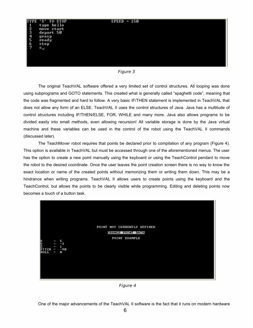
One of the biggest improvements with the TeachVAL II software is the program editor (Figure 3). Since
writing and editing programs for the robot is the main task of the user, this was made easier with TeachVAL II.
Using the old software the user needed to know what line they wanted to edit or between which two lines an
addition was intended. This caused many headaches when editing wrong lines or having to go back and figure
out the correct line numbers. TeachVAL II uses a continuous text editor with cut, copy and paste functions
available. All compile time errors are reported directly to the user and corrections can be made quickly and
easily.
5
Figure 2
The original TeachVAL software offered a very limited set of control structures. All looping was done
using subprograms and GOTO statements. This created what is generally called “spaghetti code”, meaning that
the code was fragmented and hard to follow. A very basic IF/THEN statement is implemented in TeachVAL that
does not allow any form of an ELSE. TeachVAL II uses the control structures of Java. Java has a multitude of
control structures including IF/THEN/ELSE, FOR, WHILE and many more. Java also allows programs to be
divided easily into small methods, even allowing recursion! All variable storage is done by the Java virtual
machine and these variables can be used in the control of the robot using the TeachVAL II commands
(discussed later).
The TeachMover robot requires that points be declared prior to compilation of any program (Figure 4).
This option is available in TeachVAL but must be accessed through one of the aforementioned menus. The user
has the option to create a new point manually using the keyboard or using the TeachControl pendant to move
the robot to the desired coordinate. Once the user leaves the point creation screen there is no way to know the
exact location or name of the created points without memorizing them or writing them down. This may be a
hindrance when writing programs. TeachVAL II allows users to create points using the keyboard and the
TeachControl, but allows the points to be clearly visible while programming. Editing and deleting points now
becomes a touch of a button task.
One of the major advancements of the TeachVAL II software is the fact that it runs on modern hardware
6
Figure 3
Figure 4

and is platform independent. The Java programming language only needs the proper virtual machine installed
and the software will run. Running on modern equipment allows for more reliable robot communications and
faster compilation and execution. Since the TeachVAL software runs in Java and all commands are interpreted
and sent sequentially to the robot, there is no limit to the length of the program that can be created.
7
Installation and Configuration
TeachVAL II was written and tested on an Intel Pentium 4 machine running Java Development Kit and
Runtime Environment 1.5. The software will run on any machine with the following recommended requirements:
• Intel/AMD processor minimum 1GHz
• 256MB RAM minimum
• 250MB free hard disk space (for Java Virtual Machine)
• minimum 800x600 monitor resolution
• at least one (1) available serial communications port
• mouse and keyboard for input
Running the TeachVAL II IDE
If the software is not already installed on your machine then you can download the software from the
Brock University Computer Science Department web page. Unzip the contents of the file to a folder as close to
the root as possible and with no spaces in the path name. For example “C:\TeachVALII\” will allow proper
operation of the software but “C:\Teach Val II\” will fail to resolve any communication ports. The main interface
will still load, but the communications module will fail because of the spaces within the path name. Double-
clicking ‘TeachVALII.bat’ will launch the software from the current working location.
Running TeachVAL II from a Separate IDE
The TeachVAL II library can be used in any IDE (Integrated Development Environment) that supports
Java programming. To take advantage of this capability, download the Robot.jar and comm.jar files from the
Brock University Computer Science Department web page and copy them to the current working directory of the
project you wish to use them in. The Robot.jar contains all methods and libraries for the TeachVAL II commands
as described in this manual. Be sure to include import Robot.*; at the top of the program.
This method allows you to write programs in a well known development environment but does not allow
communication with the robot during programming. Thus all points must be coded by hand and tested at runtime.
This method has the advantage of allowing several files to be edited at once thus allowing better integration with
the rest of the Java environment if needed.
8

Major Hardware Components
The TeachMover's major structural components are shown in Figure 5. The microprocessor card is
housed in the base. The TeachControl cable and the D.C. power cord extend from the rear of the base. The two
serial connectors are also located at the rear of the base. The body swivels relative to the base on a hollow shaft
attached to the base. This shaft is called the base joint.
Six stepper motors with gear assemblies are mounted on the base and control each of the six joints. The
power wires for the motors pass from the computer card in the base through a hollow shaft, to the body. This
arrangement provides a direct cable-drive system.
The upper arm is attached to the top of the body and rotates relative to the body on a shaft called the
shoulder joint. Similarly, the forearm is attached to the upper arm by another shaft known as the elbow joint.
The hand, also called the gripper, is attached to the forearm by two wrist joints. Two separate motors
operate the wrist joints to control the pitch and roll of the hand.
The TeachMover arm has a lifting capacity of one pound when fully extended, and a resolution (the
smallest amount the arm can be made to move) of 0.011 inches. The end of the hand can be positioned
anywhere within a partial sphere with a radius of 17.5 inches, as shown in Figure 6. The maximum speed is from
2 to 7 inches per second, depending upon the load (weight of the object being handled).
In general, the base, the body, and all the extension members are hollow sheet-metal parts which are
light in weight but strong. All members are connected to each other by means of shafts, or axles, passing
through bushings mounted on the members.
9
Figure 5

Figure 6
10

Arm Initialization and Calibration
The computer in the robot keeps track of the arm by using the starting position as a reference. To run a
program to operate the robot arm, you must know what the starting position was when the program was created.
To make general programming more convenient, a ''normal'' starting position is defined. This initial position
requires that the robot arm be placed exactly on a grid sheet marked off in a Cartesian coordinate system with a
scale of one inch per square. A grid sheet is included with the software as a PDF document for your
convenience.
Since the origin of the coordinate system is located at the axis of rotation within the base of the robot, the
location of the front of the robot defined as x = 1- 5/8 inches. The base is centered on the y-axis, the gripper is
brought to rest, barely touching, on the spot P0, shown on the grid at X=5 and Y=0.
**Points P1, P2, and P3 are positions at which blocks are placed for the block
stacking demonstration program included with the software.**
As shown in the illustration (Figure 7), the hand must be perpendicular to the work surface and parallel to
the front edge of the base of the robot. Keep the gripper open as you bring the arm to this position, and then
close the gripper as the last step in setting the initial position. The gripper can have a gripping force applied to it
by the motor after the point of just closing. The initial position assumes no gripping force beyond closing. The
arm can be brought to this starting position by moving it manually with the power off or by using the
teach control with the power on. After
achieving the desired starting position, be sure
to clear the internal memory of the robot.
This can be done by powering the robot off
and then on again.
Specifically, the Cartesian coordinates of
11Figure 7
Figure 8

the initial configuration are;
X = 5 inches
Y = 0 inches
Z = 0 inches
Pitch = -90o
Roll = 0o (see Note 1, below)
Grip = Closed (see Note 2, below)
Note 1: Because the hand can turn through many revolutions of ''roll,'' it is difficult to tell by simply
looking at the hand whether the ''roll'' has been set to 0o. Yet, it is important that the roll initially be 0o
in order that the wrist cables be allowed their full range of motion. To accomplish the proper initialization of
the wrist cables, turn the appropriate main drive gears until the turnbuckles on the left and right wrist cables
are aligned as shown in Figure 8. You’ll find these turnbuckles inside the forearm housing.
Note 2: For many programs, it is important that the initial position be very precise - for example, that
the fingers be just touching (grip switch closed, but no gripping force built up), and that the fingertips be
exactly horizontal and on the calibration mark at P0. To achieve this precision, it is best to key in a SPEED
number of 0, then use the joint control keys in TRAIN or MOVE mode.
12

TeachVAL II Commands
TeachVAL II commands are based on the original TeachVAL commands written for the original software.
The command syntax has been changed to comply with the conventions of Java. For example the original
TeachVAL command syntax is:
COMMAND LOCATION, VARIABLE
The COMMAND is taken from the list of available commands in the table below. These commands are
carried over to the new TeachVAL II software. The syntax of the new TeachVAL II commands is:
command(location, variable);
Again the command is taken to be any of the TeachVAL commands listed below. The above syntax
should be easily recognizable to anyone with any experience with Java.
Below is a listing all available TeachVAL II commands.
APPRO APPROS
CLOSE CLOSEI
DELAY DEPART
DEPARTS DRAW
GRASP HERE
MOVE MOVES
MOVET MOVEST
OPEN OPENI
READY SHIFT
SIGNAL SPEED
TYPE WAIT
13

APPRO
Purpose: To move the robot to the position specified with an offset along the grippers Z (up and down)
axis to the distance given.
Syntax: appro(Location location, double distance);
location is a variable of type Location that is instantiated to a reachable point for the
gripper.
distance is a double value that still allows the robot to reach the point.
Example: appro(pick, 2);
This will move the gripper to a point 2 inches above a point named ‘pick’.
APPROS
Purpose: Same as APPRO but arm is moved along a straight line path.
Syntax: appros(Location location, double distance);
location is a variable of type Location that is instantiated to a reachable point for the
gripper.
distance is a double value that still allows the robot to reach the point.
Example: appros(pick, 2);
This will move the gripper to a point 2 inches above a point named ‘pick’ along a straight
line path.
14
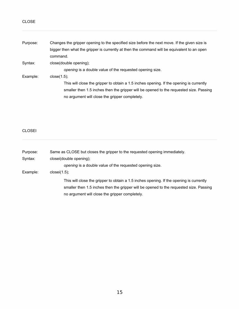
CLOSE
Purpose: Changes the gripper opening to the specified size before the next move. If the given size is
bigger then what the gripper is currently at then the command will be equivalent to an open
command.
Syntax: close(double opening);
opening is a double value of the requested opening size.
Example: close(1.5);
This will close the gripper to obtain a 1.5 inches opening. If the opening is currently
smaller then 1.5 inches then the gripper will be opened to the requested size. Passing
no argument will close the gripper completely.
CLOSEI
Purpose: Same as CLOSE but closes the gripper to the requested opening immediately.
Syntax: closei(double opening);
opening is a double value of the requested opening size.
Example: closei(1.5);
This will close the gripper to obtain a 1.5 inches opening. If the opening is currently
smaller then 1.5 inches then the gripper will be opened to the requested size. Passing
no argument will close the gripper completely.
15

DELAY
Purpose: Causes the program to stop executing for a specified number of seconds
Syntax: delay(double time);
time is a double value of the requested delay.
Example: delay(5);
This will cause program execution to stop for 5 seconds. The default value of delay is 2
seconds and is achieved by passing no parameter.
DEPART
Purpose: Moves the gripper the given distance along the gripper Z axis (up and down).
Syntax: depart(double distance);
distance is a double value of the requested departure.
Example: depart(2);
This will move the gripper a distance of 2 inches upwards from the current location. If a
negative value is passed then the gripper will move downwards.
NOTE: use caution when moving the gripper downwards taking care not to move the
gripper ‘below’ the table.
16

DEPARTS
Purpose: Moves the gripper the given distance along the gripper Z axis (up and down) along a straight line
path.
Syntax: departs(double distance);
distance is a double value of the requested departure.
Example: departs(2);
This will move the gripper a distance of 2 inches upwards from the current location using
a straight line path. If a negative value is passed then the gripper will move downwards.
NOTE: use caution when moving the gripper downwards taking care not to move the
gripper ‘below’ the table.
DRAW
Purpose: To move the gripper an incremental amount.
Syntax: draw(double distanceX, double distanceY, double distanceZ);
distanceX is a double value of the requested distance in the X axis.
distanceY is a double value of the requested distance in the Y axis.
distanceZ is a double value of the requested distance in the Z axis.
Example: draw(2, -3 4);
This will move the gripper a distance of 2 inches along the positive X axis, 3 inches
along the negative Y axis and 4 inches along the positive Z axis. Any of the values can
be 0 if you do not wish to change that particular location.
NOTE: use caution when moving the gripper downwards taking care not to move the
gripper ‘below’ the table.
17
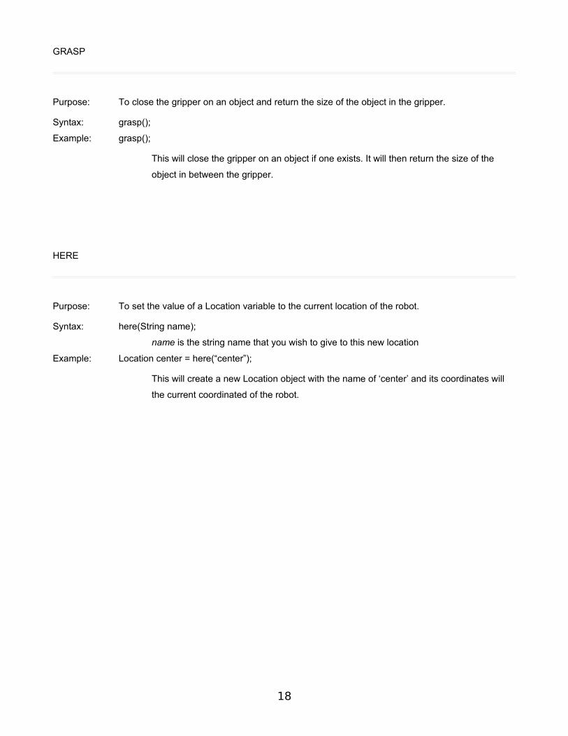
GRASP
Purpose: To close the gripper on an object and return the size of the object in the gripper.
Syntax: grasp();
Example: grasp();
This will close the gripper on an object if one exists. It will then return the size of the
object in between the gripper.
HERE
Purpose: To set the value of a Location variable to the current location of the robot.
Syntax: here(String name);
name is the string name that you wish to give to this new location
Example: Location center = here(“center”);
This will create a new Location object with the name of ‘center’ and its coordinates will
the current coordinated of the robot.
18

MOVE
Purpose: To move the robot to the position and orientation specified.
Syntax: move(Location loc);
loc is the name of a previously defined Location object.
Example: move(center);
This will move the robot to the location described by the Location object named ‘center’.
NOTE: Location objects can be created using software by clicking on “Add New Point”
or by manually coding them.
MOVES
Purpose: To move the robot to the position and orientation specified. Very similar to MOVE but this
command moves the robot along a straight line path
Syntax: moves(Location loc);
loc is the name of a previously defined Location object.
Example: moves(center);
This will move the robot to the location described by the Location object named ‘center’
along a straight line path from the current location.
NOTE: Location objects can be created using software by clicking on “Add New Point”
or by manually coding them.
19

MOVET
Purpose: To move the robot to the position and orientation specified, by first setting the gripper opening to
the requested size.
Syntax: movet(Location loc, double opening);
loc is the name of a previously defined Location object.
opening is a double value of the requested gripper opening.
Example: movet(center, 1.5);
This will move the robot to the location described by the object named ‘center’ but first
the gripper opening will be set to 1.5 inches.
NOTE 1: Location objects can be created using software by clicking on “Add New Point”
or by manually coding them.
NOTE 2: Setting the gripper opening may involve opening or closing the gripper. This
will depend on the previous opening before this command is issued.
MOVEST
Purpose: To move the robot to the position and orientation specified along a straight line path, by first
setting the gripper to the requested size.
Syntax: movest(Location loc, double opening);
loc is the name of a previously defined Location object.
opening is a double value of the requested gripper opening.
Example: movest(center, 1.5);
This will move the robot to the location described by the object named ‘center’ along a
straight line path but first the gripper opening will be set to 1.5 inches.
NOTE 1: Location objects can be created using software by clicking on “Add New Point”
or by manually coding them.
NOTE 2: Setting the gripper opening may involve opening or closing the gripper. This
will depend on the previous opening before this command is issued.
20

OPEN
Purpose: To change the gripper opening immediately prior to the next move statement to the desired size.
Syntax: open(double opening);
opening is a double value of the requested gripper opening.
Example: open(2.25);
This will set the gripper opening to a width of 2.25 inches. If the current opening is
smaller then 2.25 inches then the opening will get wider, if it is wider the gripper will
close to the desired size.
NOTE: If no parameter is passed the default opening is 2 inches.
OPENI
Purpose: To change the gripper opening immediately to the desired size.
Syntax: openi(double opening);
opening is a double value of the requested gripper opening.
Example: openi(2.25);
This will set the gripper opening to a width of 2.25 inches. If the current opening is
smaller then 2.25 inches then the opening will get wider, if it is wider the gripper will
close to the desired size.
NOTE: If no parameter is passed the default opening is 2 inches.
21
READY
Purpose: To move the robot arm to the initial (home) position.
Syntax: ready();
Example: ready();
This will move the robot arm to the initial position that is generally called the HOME
position.
NOTE: Take caution that the robot arm does not strike anything when moving to the
READY position.
SHIFT
Purpose: To modify the X, Y and Z coordinated of a Location variable.
Syntax: shift(Location loc, double x, double y, double z);
loc is the Location object that you wish to shift.
x,y,z are double values corresponding to the desired shift of each of the coordinates.
Example: shift(center, 2, 0, -1);
This will shift the coordinates of the location named ‘center’ 2 inches in the positive X
direction, 0 inches in the Y direction and 1 inch in the negative Z direction.
NOTE 1: If you do not want to shift a particular coordinate just leave a 0 in the proper
place.
NOTE 2: Be careful when shifting the Z coordinate not to allow the gripper to move
‘below’ the table.
22

SIGNAL
Purpose: To turn the robot output ports ON or OFF.
Syntax: signal(integer whatPort[]);
whatPort can be a single integer or an array of integers between -5 and 5
Example: signal(-3);
This sets the 3rd output port to go low (become 0). If the output port is already low then
there will be no change.
SPEED
Purpose: Changes the speed of execution of the proceeding robot commands by the given speed. This
speed is maintained until the program finishes executing or until another SPEED command
changes the speed.
Syntax: speed(int speed);
speed is an integer value between 0 and 240 corresponding to the desired speed.
Example: speed(Microbot.MEDIUM);
This will set the speed of execution to the MEDIUM speed set in the class Microbot. This
speed corresponds to a value of 190.
NOTE: If the given speed is greater then 240 the default of 240 will be set. Also if the
given speed is less then 0 then 0 will be set as the speed.
23

TYPE
Purpose: To display a message on the screen.
Syntax: type(String text);
text is a String that you wish to appear on the screen.
Example: type(“Start of program”);
This will print “Start of program” (without the quotes) to the system output window.
WAIT
Purpose: To suspend program execution until a desired input status is achieved.
Syntax: wait(integer whatPort[]);
whatPort can be a single integer or an array of integers between -7 and 7
Example: int array[] = {-3, 2, 7};
wait(array);
This will suspend program execution until input port 3 becomes low and inputs 2 and 7
become high.
24

How to Use TeachVAL II
The TeachVAL II software provides all the features of the original TeachVAL software but on one simple
easy to read screen. TeachVAL II is written in Java and allows users to write Java programs to control the
robots. The original TeachVAL commands have been ported to Java thus allowing a much more structured and
robust programming environment. For most users TeachVAL II should be easy to grasp as it is modeled on
some of the current IDEs (Integrated Development Environments) being used to develop software.
Starting TeachVAL II
The splash screen (Figure 9) first appears when the software is started. During this process all interface
components and modules are loaded and the software is readied to run on your system.
The main screen is shown on the next page (Figure 10). Here you can see the main components of the
user interface. The prominent feature is the ‘Editor’ pane that allows user programs to be written and edited with
ease. The ‘Editor’ pane acts as any simple text editor, allowing you to freely type your program without
restrictions on length and format. The ‘Edit’ menu contains three options related to editing text:
• Cut<CTRL> + X
• Copy <CTRL> + C
• Paste <CTRL> + V
These functions are invaluable to most programmers and can also be accessed by using the standard keyboard
shortcuts as defined above.
25
Figure 9

Men
uP
rogr
am E
dito
r
Ava
ilable
Poin
ts
Poin
t
Editi
ng
Button
s
Sta
tus
Bar
Com
pile
r/
Exe
cutio
n
Outp
ut
Lin
e
Num
bers
Figure 10
File Menu
26

The ‘File’ menu (Figure 11) allows the creation of new programs. By selecting ‘New’ you are presented
with two (2) options, create a new project from an empty file or from a pre defined default template. The default
template allows a consistent format to be followed and contains all the default code to make sure the project will
compile and run immediately.
Figure 11
Opening and saving documents is as simple as selecting the appropriate option from the ‘File’ menu.
Each option will show a dialog appropriate to the task and allow you to choose the file to open or the file to save
to. The default file type to open or save to is ‘.java’.
Project Menu
The ‘Project’ menu (Figure 12) allows you to compile and run the project when needed. It contains three
options for the user:
• Compile
• Run
• Compile then Run
The ‘Compile’ option will compile the code currently within the editor window. Any compilation errors will
be shown in the ‘Output’ window at the bottom of the screen. These errors need to be corrected in order to
obtain a project that can be run.
If compilation is successful the ‘Run’ option will become enabled and if it is subsequently selected then
the compiled program will be executed. Be careful when executing programs, ensuring that the robot is plugged
in and turned on. Also be sure the have the vicinity clear of all obstructions so as not to interfere with the robotic
arm movement.
27

Figure 12
The ‘Compile then Run’ option is always available. Selecting it will compile the code within the window
and, if there are no compilation errors, run the compiled program. This provides a one click option that you may
prefer.
Adding a New Point
Adding a new point to memory is as simple as clicking the ‘Add New Point’ button in the ‘Available
Points’ box. The buttons in this panel will only be available if a proper communications port is open between the
host computer and the robot. If you have not done this yet refer to the appropriate section for instructions.
Once the ‘Add New Point’ button is pressed the ‘Add New Point’ dialog will appear (Figure 13). There
are two (2) different ways of adding points to memory.
• Using the Keyboard
• Using the TeachControl Pendant
The default option is to create a new point using the keyboard to enter the coordinates. The ‘OK’ button will be
disabled until at least one character name is entered into the ‘Name’ box.
28
Figure 13

Creating a Point Using the Keyboard
To create a point using self defined coordinates and the keyboard simply type the desired coordinates
into the appropriate fields. The default value for all fields is 0. Be careful to only enter coordinates that the robotic
arm can actually reach. Refer to Figure 6 for the arm limits. Once a name is entered into the ‘Name’ field the
‘OK’ button will be enabled and pressing it will add the new point to the ‘Available Points’ table (Figure 14).
Creating a Point Using the TeachControl
To create a point using the TeachControl pendant simply click the ‘Using TeachControl’ button at the top
of the dialog. This will change the dialog to allow you to move the robotic arm using the TeachControl pendant to
any point you wish. This allows you to create points for which the exact numeric values are unknown. The only
input required in this mode is a name for the point. Once a name is entered into the ‘Name’ field the ‘OK’ button
will be enabled and pressing it will add the new point to the ‘Available Points’ table (Figure 14). If you wish to go
back to manual coordinate input click ‘Using Keyboard’ at the top of this dialog.
Deleting or Editing Points
The ‘Available Points’ box shows what points are currently in memory and allows you to edit and delete
any number of desired points. To select multiple points hold down the <CRTL> key while clicking rows within the
table. Once the desired points are selected, click the ‘Delete Point(s)’ button. A confirmation dialog will appear
and if ‘Yes’ is selected the deleted points will disappear from the table.
The ‘Edit Point’ button will allow you to edit the current selected point’s coordinates using either the
keyboard or TeachControl as described earlier. Clicking the ‘Edit Point’ button will show a dialog populated with
the point’s coordinates. ‘Cancel’ will leave the coordinates unchanged while ‘OK’ will apply the new values.
The ‘Available Points’ box contains a button named ‘Where am I?’. Clicking this button will display the
current coordinates of the robot arm in the ‘Output’ window (Figure 15).
29
Figure 14
Figure 15

Opening Ports
To allow communication between the host computer and the robot a serial communication port must be
opened. The main menu has an option to allow the opening of these ports and clicking this option will open the
‘Open Port’ dialog (Figure 16). This dialog displays the available serial communication ports on your machine.
The default port will be COM1 if it is available on your computer. If you are informed that there are no
ports available then there may be a problem with the installation of the software or the hardware that it is running
on. A reinstall and restart of the software may be necessary to correct this problem.
Clicking on ‘OK’ will open the selected port and establish communication between the host computer
and the robot. If the communication test is successful the four buttons in the ‘Available Points’ box will be set to
enabled and you will be able to send commands to the robot.
Exiting TeachVAL II
The ‘File’ Menu contains the option to exit the program. Selecting this option will close all open
communication ports and close the main window. A confirmation dialog will appear, and choosing ‘No’ will cancel
the exit operation. Before exiting be sure to save any work in your home directory as the working directory of the
software will be purged of all temporary files on exit.
30
Figure 16

The Future
The TeachMover robots are very capable machines. Using the appropriate software and programming
techniques these robots can be made to do many things. Using the TeachVAL II communication interface for the
robots any number of pieces of software can be written to control the robots.
One possibility is using a three dimensional illustration on the screen to allow the user to click and drag
components and then have the robot imitate these movements. This would create a crude virtual reality where
the user can move the robots in real time using a mouse and keyboard as inputs. The current TeachVAL II
communications interface is set up so that virtual movements of the on screen robot can be translated and then
sent in real time.
Another interesting possibility is the integration with the TeachVision software to allow the robot to “see”
its surroundings. The current TeachVision software still leaves much to be desired but once it has been updated
it is entirely possible to combine TeachVAL II with TeachVision. One possibility is having the robot play chess or
checkers. Using the TeachVision to allow the robot to “see” the game board and then incorporating some game
playing intelligence and the TeachVAL II software to move the robots pieces around the board is entirely
possible. Using two robots and the communication module a virtual tournament can be played between two
robots!
31
References
“Operation of the Five-Axis Robot Model TCM” UMI-MICROBOT INC. Edition 5, 1989
“TeachVAL: Robot Programming Language” UMI-MICROBOT INC. 1988
32