Embed Size (px)
Citation preview
Microbial shaping of sedimentary wrinkle structures
G. Mariotti1, S. B. Pruss2, J.T. Perron1, T. Bosak1
1. MIT, Department of Earth, Atmospheric and Planetary Sciences, Cambridge, MA, USA.
2. Smith College, Department of Geosciences, Northampton, MA, USA.
SUPPLEMENTARY TEXT
Microbial shaping of sedimentary wrinkle structures
SUPPLEMENTARY INFORMATIONDOI: 10.1038/NGEO2229
NATURE GEOSCIENCE | www.nature.com/naturegeoscience 1

1. Wrinkle structures – examples and observations
Wrinkle structures is a collective term that includes two similar sedimentary features1:
wrinkle marks2 and Kynneia3. In this context we only refer to wrinkle structures and, following a
classification based on surface relief4 , we differentiate between structures with a “positive
relief”, i.e. ridges, and with a “negative relief”, i.e. pits.
Fig. S1. Image of patchy wrinkle structures from an outcrop. Ridge and Pit wrinkle structures
are present on the same bedding plane. Swiss Army knife for scale. The location is the Upper
Cambrian Big Cove Member of the Petit Jardin Formation, near Marches Point on the Port au
Port Peninsula in western Newfoundland.

2. Are ridges small wave ripples?
In the orbital ripples regime, ripple wavelength is approximately proportional to the
orbital amplitude A of the wave at the surface of the bed5,
( )0.342.2 0.345Aλ φ= − , (Eq. S1)
where ϕ is the mobility number, equal to ( )2 /w m s wU g Dρ ρ ρ− , ρw and ρs are the water and
sediment density, g is the gravitational acceleration, D is the median grain diameter, Um is the
maximum orbital velocity, 2 /mU A Tπ= , at the bed surface and T is the wave period.
This theory suggests that ridges might be formed by waves with a small bed amplitude
excursion. However, only bed orbital velocities that are large enough to move sand grains can
form ripples. Laboratory and field data indicate that this condition is met when the mobility
parameter is greater than about 2[ref. 6]. Such constraint is a lower bound: indeed, if no initial bed
perturbations are present, the threshold mobility parameter is even larger than 2. For a fixed
wave period, the orbital velocity and the mobility parameter decrease with the bed amplitude
excursion. Consequently, for a fixed wave period and grain size, there is a minimum value of the
bed amplitude excursion or, equivalently, a minimum ripple wavelength below which ripples do
not form (Fig S2).

Fig. S2. Smallest ripple wavelength that can be formed abiotically, calculated setting ϕ=2[ref.
6], as a function of sand grain size and wave period. Continuous lines for quartz sand (ρs
=2650 kg/m3), dashed lines for aragonite sand (ρs =2800 kg/m3).
Even for very short wave periods, e.g. equal to about 1 s as used in our experiments,
ripples with a wavelength shorter than 30 mm do not form in fine sand (D= 250 µm), a grain size
typical for wrinkle structures. For sediment with smaller grain sizes (D=50 µm), ripples with a
wavelength of 10 mm only form with a wave period shorter than 1 s. For longer wave periods,
more common in natural settings, the threshold wavelength is longer than 10 mm. The cohesion
of grains smaller than 50 µm increases the critical shear stress for motion and prevents the
formation of ripples with very small wavelengths. This analysis indicates that wave ripples with
small wavelength (5-10 mm) can form abiotically only in very restricted conditions, i.e. with
silty sediments and with very short wave period (0.5 s), possibly occurring in very shallow water.
The restriction of this abiotic mechanism to a very narrow setting suggests that it does not
account for the widespread presence of wrinkle structures in the rock record.
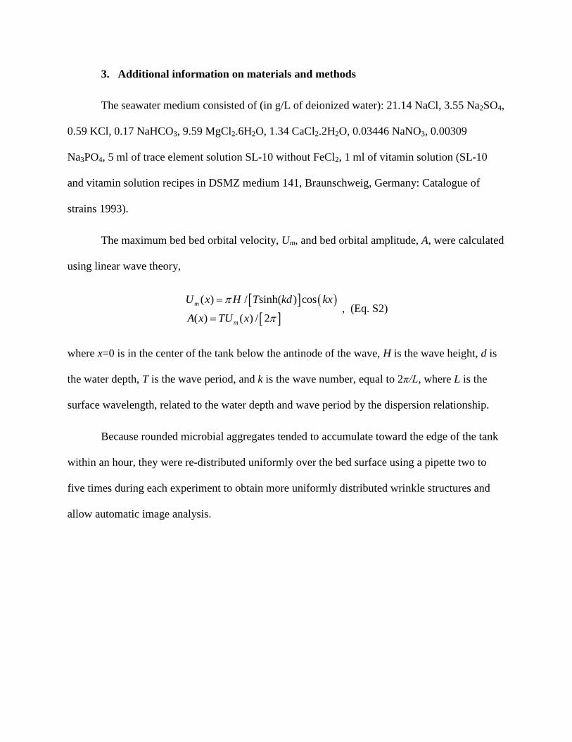
3. Additional information on materials and methods
The seawater medium consisted of (in g/L of deionized water): 21.14 NaCl, 3.55 Na2SO4,
0.59 KCl, 0.17 NaHCO3, 9.59 MgCl2.6H2O, 1.34 CaCl2.2H2O, 0.03446 NaNO3, 0.00309
Na3PO4, 5 ml of trace element solution SL-10 without FeCl2, 1 ml of vitamin solution (SL-10
and vitamin solution recipes in DSMZ medium 141, Braunschweig, Germany: Catalogue of
strains 1993).
The maximum bed bed orbital velocity, Um, and bed orbital amplitude, A, were calculated
using linear wave theory,
[ ] ( )[ ]
( ) / sinh( ) cos
( ) ( ) / 2m
m
U x H T kd kx
A x TU x
π
π
=
= , (Eq. S2)
where x=0 is in the center of the tank below the antinode of the wave, H is the wave height, d is
the water depth, T is the wave period, and k is the wave number, equal to 2π/L, where L is the
surface wavelength, related to the water depth and wave period by the dispersion relationship.
Because rounded microbial aggregates tended to accumulate toward the edge of the tank
within an hour, they were re-distributed uniformly over the bed surface using a pipette two to
five times during each experiment to obtain more uniformly distributed wrinkle structures and
allow automatic image analysis.

Fig. S3. (A) Schematic diagram of the wave tank, viewed from the top. The dashed rectangle
indicates the images in Fig. S4. (B) Maximum bed orbital velocity, computed using linear
wave theory (Equation S2), for different wave heights. (C) Schematic diagram of the wave
tank, viewed from the front side. Blue lines represent the surface wave envelope; black
horizontal arrows represent the bed orbital amplitude, which varies from a maximum in the
middle of the tank to zero at the edges of the tank.

4. Measurements of ridge morphology
The tank was illuminated by a light held 20 cm away from the short side of the tank and
20 cm above the bed. Photographs taken with a camera held parallel to the bed captured the half
of the tank opposite to the wave maker (Fig. S3A). A 5-cm wide rim next to the tank walls was
cropped out of the photos to avoid possible boundary effects. The resulting images covered an
area of 20 x 32.5 cm, with a pixel size of ~1 mm. Each image was converted into a scalar matrix
whose values were the sum of the three visible bands. The average value of the matrix intensity
was subtracted from the original values, and the ripple wavelength was computed using a zero-
crossing method, i.e. by identifying changes in the sign of the matrix value 7. Results were
divided into 2-cm wide bins parallel to the short side of the tank. The median wavelength was
computed for each bin. Using this method, a background wavelength of about 2 mm on the
initially flat bed was determined as the bed noise. This method was not applied to the pits
because the patchiness and the lack of regular patterns.
5. Formation of ridges in fine and very fine sand
The experiments creating ridges were replicated using very fine sand (D = 100 μm)
instead of fine sand (D = 250 μm). As predicted by theory, the threshold for abiotic ripple
formation in the very fine sand was lower than for fine sand: ripples formed in the absence of
mat fragments when the wave amplitude was greater than about 12 mm (Fig. S4). In the regime
where ripples cannot form abiotically, i.e. for wave amplitudes smaller than 12 mm, microbial
aggregates formed ripples with a similar relationship between their wavelength and the wave
orbital amplitude. This indicated that the sand grain size did not affect the mechanism of ridge
formation by particle rolling.

Fig. S4. Comparison of ridged wrinkle structures created with microbial aggregates on fine
sand (D = 250 µm) and very fine sand (D = 100 µm). (A) The wavelength of ripples is
plotted as a function of the orbital amplitude for a wave period of 1.2 s. Lines are the
predicted relationship 5 using the two sand grain sizes. Note that the scaling between
wavelength and bed orbital amplitude differs from that of abiotic wave ripples, possibly
because the bed excursion amplitude of the mat fragments is smaller than the bed orbital

amplitude of the near-bed fluid. The green areas show the regime in which ripples are
predicted to form abiotically (ϕ>2). Note that the transition to this regime depends on the size
of sand grains. The white area shows the regime in which ripples cannot form in the absence
of microbial aggregates. The pink area shows the regime in which rounded mat fragments
cannot be mobilized. (B) Comparison of ripples formed by rolling, rounded mat fragments,
with two different sand grain sizes and two wave heights (experiments R250/15, R250/30, R100/15,
R100/30 in Table 1). Note the variability in ripple wavelength due to the spatially variable wave
orbital velocity at the bed surface (Fig. S3).

Fig. S5. Wrinkle structures in the wave tank and in the rock record. The same same scale is
used in all the images. A) Wrinkle structures with ridge and pit morphology formed in
different areas of the same bed (in the same experiment) when both rounded and well-
dispersed microbial aggregates were present [D=250 μm, and H=15 mm (experiment RS250/15
in Table 1)]. Note the presence of patches with wrinkle structures and the variability within
areas characterized by the same bed orbital amplitude (yellow vertical boxes). B) Patch of
large ridged wrinkle structures with a wavelength up to 2 cm from the Upper Silurian
Burgsvik Formation on Gotland (Sweden). Image adapted from Calner and Eriksson (2011)8.
C) Patches of pitted wrinkle structures from the Upper Cambrian Big Cove Member of the
Petit Jardin Formation, near Marches Point on the Port au Port Peninsula in western
Newfoundland.
6. Wave conditions that form ridges
Our experiments suggest that wrinkle structures can be formed by waves with very small
orbital amplitude, provided that light material is available. For example, a wave with bed orbital
amplitude of 5-10 mm can form wrinkle structures with wavelengths from 3 to 10 mm (Fig. 3A).
In natural settings, a bed orbital amplitude of 10 mm can arise from different combinations of
water depths and wave heights. Some of these combinations are associated with large orbital
velocities that are able to form ripples abiotically, e.g. ϕ>2 (Fig. S2), while others include small
orbital velocities that are not able to move the low-density particles and create wrinkle structures.
The latter conditions translate to τ<τcr_p, where τ is the fluid shear stress and τcr_p is the critical
shear stress required to move mat fragments. We estimated the bed shear stress as
( )( )21/ 2 / sinh
wf H T kdτ ρ π= , where fw is a friction factor, set equal to9

( ) [ ][ ]
0.194exp 5.213 2.5 / 5.977 / 2.5 1.57
0.3 / 2.5 1.57w
D A A Df
A D
− > = ≤
. (Eq. S3)
Experimental constraints described in the main text suggest that the mat fragments that
create wrinkle structures in the presence of microbial aggregates have a diameter of about 2 mm
and a density of 1050 g/l. The Shields criterion estimates τcr_p = 0.01 Pa for these parameters10.
By using the physical constraint of wave breaking, i.e. H/L = 0.14 tanh (2πd/L)[ref. 11], we
can further narrow the range of water depths and wave heights that are able to form wrinkle
structures (Fig. S6). This analysis suggests that ridges can form in water depths from 0.1 m to
100 m.
Fig. S6. Wave orbital velocity and period as functions of water depth and wave height that
can harbor waves with a bed orbital amplitude of 10 mm. This amplitude creates ridges with
a wavelength of about 10 mm when low-density particles are present (Fig. 2). Wave breaking
conditions limit the possible combinations of wave height and orbital velocities (see ref. 12

for a similar calculation). For high bed orbital velocities, ripples form abiotically (ϕ >2).
However, this scenario occurs only in very shallow water (<0.2 m), and for very low wave
period (T<1 s). For low orbital velocities, fluid shear is not able to move light particles and
ridges cannot form. The range of wave orbital velocities and periods that can create small
ripples (ridged wrinkle structures) in the presence of microbial aggregates is shaded in grey.
The black circle indicates the conditions used in our laboratory experiments.
7. Superimposition of waves and currents
In natural environments waves are often associated with some currents, which might
affect the interaction between mat fragments and the sandy bed. Our model suggests that wrinkle
structures form with very small bed orbital amplitudes. This implies the presence of small
surface waves, small wind speed and small wind-induced currents. In addition, small surface
waves have a small second-order component, hence a small Stokes drift. Because wrinkle
structures form in a relative short time (< 1 hour), a small drift, caused by wind induced currents
or second-order wave components, would not prevent wrinkle structure formation.
To summarize, according to our mechanism, a perfect oscillatory flow is not a
requirement for the formation of wrinkle structures.

List of videos
Video 1. Formation of ridges. Experiment with D = 250 µm, H=30 mm, and rounded mat
fragments (experiment R250/30 in Table 1). Wave conditions were kept constant during the
experiment. View is centered in the middle of the tank where orbital amplitudes are about 10
mm. Mat fragments were added to the tank approximately half an hour into the experiment. Note
that sediments do not move in the absence of mat fragments, and that ridges form in about 1
hour.
Video 2. Close-up view of microbial aggregates rolling over a small ripple (wrinkle structure).
Experiment with D = 250 µm, H=30 mm, and rounded mat fragments (experiment R250/30 in
Table 1). View is centered in the middle of the tank where orbital amplitudes are about 10 mm.
Note that some sand grains move when the mat fragment rolls over the ripple crest. The period of
the oscillations is 1.2 s. The size of the large mat fragment is about 3 mm. Individual grains can
be used for scale. The video is taken about 2 hours into the experiment.
Video 3. Formation of pits. Experiment with D = 250 µm, H=7 mm, and shredded mat fragments
(experiment S250/7 inTable S1). The final frame shows the bed after mat fragments have been
removed.
Video 4. Close-up video of pit formation. Experiment with D = 250 µm, H=7 mm, and shredded
mat fragments (experiment S250/7 in Table 1). The period of the oscillations is 1.2 s. Note that the
shredded mat fragments that anchor to the bed oscillate and produce scour pits in few hours.
Videos are taken about 2 hours into the experiment.
Video 5. Close-up video of pit formation. Experiment with D = 250 µm, H=7 mm, and shredded
mat fragments (experiment S250/7 inTable 1). The period of the oscillations is 1.2 s. Note that the

shredded mat fragments that anchor to the bed oscillate and produce scour pits in few hours.
Videos are taken about 2 hours into the experiment.
Video 6. Close-up video of pit formation. Experiment with D = 250 µm, H=7 mm, and shredded
mat fragments (experiment S250/7 inTable 1). The period of the oscillations is 1.2 s. Note that the
shredded mat fragments that anchor to the bed oscillate and produce scour pits in few hours.
Videos are taken about 2 hours into the experiment. Colors in video 6 differ from video 4 and 5
because of different light settings.
Video 7. Close-up video of large mat aggregates oscillating over the bed, in the mid portion of
the tank where orbital amplitudes are larger than 4 mm. Experiment with D = 250 µm, H=15
mm, and shredded mat fragments (experiment S250/15 in Table 1). Note that the large aggregate
does not anchor to the bed and do not move any sand.
Video 8. Close-up view of microbial aggregates rolling over a sand surface colonized by a ~1
mm thick microbial mat grown with light and nutrients. Note that the particles do not destroy the
mat or move sand grains.
References
1. Hagadorn, J. W. & Bottjer, D. J. Wrinkle structures: Microbially mediated sedimentary
structures common in subtidal siliciclastic settings at the Proterozoic-Phanerozoic transition.
Geology 25, 1047–1050 (1997).
2. Hantzschel, W. & Reineck, H.E. Fazies-Untersuchungen im hettangium von Helmstedt
(Niedersachsen). Mitt GeoL Staatsinst Hambg. 37, 5–39 (1968).

3. Martinsson, A. Aspects of a middle Cambrian Thanatotope on Oland. Geol Foren Stockh Forh
87, 181–230 (1965).
4. Banerjee, S. & Jeevankumar, S. Microbially originated wrinkle structures on sandstone and
their stratigraphic context: Palaeoproterozoic Koldaha Shale, central India. Sediment. Geol.
176, 211–224 (2005).
5. Nielsen, P. Dynamics and geometry of wave-generated ripples. J. Geophys. Res. Oceans 86,
6467–6472 (1981).
6. Sekiguchi, T. & Sunamura, T. Threshold for ripple formation on artificially roughened beds:
Wave-flume experiments. J. Coast. Res. 21, 323–330 (2005).
7. Hurt, N. E. Phase retrieval and zero crossings: Mathematical methods in image reconstruction.
Springer (2001).
8. Calner, M. & Eriksson, M. E. The record of microbially induced sedimentary structures
(MISS) in the Swedish Paleozoic. In Microbial mats in siliciclastic depositional systems
through time (Noffke, N. & Chafetz, H.), S E P M - Soc. Sedimentary Geology, 101, 29–35
(2012).
9. Jonsson, I. G. Wave boundary layers and friction factors. Coast. Eng. Proc. 1, (2011).
10. Chen, W.F. The civil engineering handbook. CRC Press, 1-2904 (1995).
11. Miche, R. Le pouvoir réfléchissant des ouvrages maritime exposés à l’action de la houle.
Ann. Ponts Chaussees 121, 285–319. (1951).
12. Lamb, M. P., Fischer, W. W., Raub, T. D., Perron, J. T. & Myrow, P. M. Origin of giant
wave ripples in snowball Earth cap carbonate. Geology 40, 827–830 (2012).