Embed Size (px)
DESCRIPTION
combustion handbook radiation
Citation preview
How do I predict radiative heat transfer in industrial furnaces?
A Combustion File downloaded from the IFRF Online Combustion Handbook ISSN 1607-9116
Combustion File No: 65
Version No: 1
Date: 14-06-2004
Author(s): Robert J Tucker
Source(s): See CF
Referee(s): Alan Jones (Imperial College, London)
John Ward (University of Glamorgan)
Sub-editor: Robert Tucker
Status: Published
Sponsor: Zerontec Ltd
1. The need for radiation models An accurate model of the thermal radiation in furnaces is important for predicting overall thermal efficiency, production rates, quality of the heated product, and pollutant emissions. The prediction of radiative transfer is complex due to the multidimensional and spectral nature of radiation. Thermal radiation exchange is the dominant mode of heat transfer in most furnaces and it depends on many factors including position, local temperature and composition. In order to make progress, a number of techniques have been developed which all introduce simplifying assumptions suited to the particular application or modelling approach.
In a furnace enclosure, the flame and hot combustion gases emit radiation. The radiation is transferred to the load surface via a complex process including:
Direct radiation from the flame and combustion products
Direct radiation from other surfaces (walls) forming the enclosure
Radiation emitted by the gases, that arrives indirectly at the load surface after multiple reflections off the walls and other surfaces in the enclosure. This includes radiation which itself is reflected off the load and re-reflected back to the load.
Radiation that is partially reabsorbed (attenuated) by the gases or scattered by particles as it passes through the furnace space. Soot or mineral matter in the flame and combustion products may cause scattering.
The problem is further complicated by the fact that combustion gases are not grey. Simple models assume grey behaviour. More complex models include allowance for non-grey gas behaviour.
Furthermore, the combustion atmosphere may not be homogeneous in composition. Where flames extend into the furnace volume, then the composition of radiating components (CO2, H2O, carbon and particulate matter) can vary significantly with position as the air and fuel mix, and as combustion progresses.
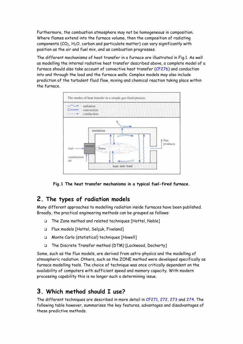
The different mechanisms of heat transfer in a furnace are illustrated in Fig.1. As well as modelling the internal radiative heat transfer described above, a complete model of a furnace should also take account of convective heat transfer (CF276) and conduction into and through the load and the furnace walls. Complex models may also include prediction of the turbulent fluid flow, mixing and chemical reaction taking place within the furnace.
Fig.1 The heat transfer mechanisms in a typical fuel-fired furnace.
2. The types of radiation models Many different approaches to modelling radiation inside furnaces have been published. Broadly, the practical engineering methods can be grouped as follows:
The Zone method and related techniques [Hottel, Noble]
Flux models [Hottel, Selçuk, Fiveland]
Monte Carlo (statistical) techniques [Howell]
The Discrete Transfer method (DTM) [Lockwood, Docherty]
Some, such as the flux models, are derived from astro-physics and the modelling of atmospheric radiation. Others, such as the ZONE method were developed specifically as furnace modelling tools. The choice of technique was once critically dependent on the availability of computers with sufficient speed and memory capacity. With modern processing capability this is no longer such a determining issue.
3. Which method should I use? The different techniques are described in more detail in CF271, 272, 273 and 274. The following table however, summarises the key features, advantages and disadvantages of these predictive methods.
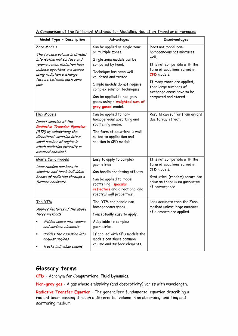
A Comparison of the Different Methods for Modelling Radiation Transfer in Furnaces
Model Type - Description Advantages Disadvantages
Zone Models
The furnace volume is divided into isothermal surface and volume zones. Radiation heat balance equations are solved using radiation exchange factors between each zone pair.
Can be applied as single zone or multiple zones.
Single zone models can be computed by hand.
Technique has been well validated and tested.
Simple models do not require complex solution techniques.
Can be applied to non-grey gases using a ‘weighted sum of grey gases‘ model.
Does not model non-homogeneous gas mixtures well.
It is not compatible with the form of equations solved in CFD models.
If many zones are applied, then large numbers of exchange areas have to be computed and stored.
Flux Models
Direct solution of the Radiative Transfer Equation(RTE) by subdividing the directional variation into a small number of angles in which radiation intensity is assumed constant.
Can be applied to non-homogeneous absorbing and scattering media.
The form of equations is well suited to application and solution in CFD models.
Results can suffer from errors due to ‘ray effect’.
Monte Carlo models
Uses random numbers to simulate and track individual beams of radiation through a furnace enclosure.
Easy to apply to complex geometries.
Can handle shadowing effects.
Can be applied to model scattering, specular reflectors and directional and spectral wall properties.
It is not compatible with the form of equations solved in CFD models.
Statistical (random) errors can arise so there is no guarantee of convergence.
The DTM
Applies features of the above three methods:
divides space into volume and surface elements
divides the radiation into angular regions
tracks individual beams
The DTM can handle non-homogeneous gases.
Conceptually easy to apply.
Adaptable to complex geometries.
If applied with CFD models the models can share common volume and surface elements.
Less accurate than the Zone method unless large numbers of elements are applied.
Glossary terms CFD – Acronym for Computational Fluid Dynamics.
Non-grey gas - A gas whose emissivity (and absorptivity) varies with wavelength.
Radiative Transfer Equation – The generalised fundamental equation describing a radiant beam passing through a differential volume in an absorbing, emitting and scattering medium.
Scattering – The change in direction of propagation of radiation by the incidence of photons with particles (e.g. soot) or droplets and sometime molecules in a medium.
Specular reflectors – A smooth reflecting surface behaving like a mirror, in which the angle of reflection equals the angle of incidence.
Weighted sum of grey gases – An approximation used to represent non-grey combustion products by a weighted summation of two or more grey gases plus a clear gas.
Keywords Radiation, Zone method, Flux method, Monte Carlo, Discrete Transfer Method, Heat Transfer
Related Combustion Files 271 – What is the Zone method?
272 – What are Flux models?
273 – What is the Monte Carlo method?
274 – What is the Discrete Transfer method?
276 – What is convective heat transfer?
Sources
1. Hottel H.C. and Sarofim A.F., Radiative Transfer, McGraw-Hill, 1967.
2. Noble J.J., ‘The Zone Method: Explicit Matrix Relations for Total Exchange Areas’, Int.J.Heat Mass Transfer, vol. 18, pp. 261-269, 1975.
3. Selçuk N., ‘Evaluation of Flux Models for Radiative Transfer in Rectangular Furnaces’, Int.J.Heat Mass Transfer, vol. 13, no.7, pp. 1477-1482, 1988.
4. Fiveland W.A., ‘Discrete-ordinates solutions of the Radiative Transport Equation for Rectangular Enclosures’, J.of Heat Transfer, vol.106, pp. 699-706, 1984.
5. Howell J.R., ‘Application of Monte Carlo to Heat Transfer Problems’, in Advances in Heat Transfer (T.F.Irvine and J.P.Hartnett, eds.), vol.5, Ac.Press, 1968.
6. Lockwood F.C., Shah N.G., Eighteenth Symposium (International) on Combustion, The Combustion Institute, 1981, pp 1405-1414
7. Docherty P., Fairweather M., ‘Predictions of Radiative Transfer from Non- homogeneous Combustion Products Using Discrete Transfer Method’, Combustion and Flame 71, 79-87 (1988).
Acknowledgements None
File Placing [Basic Scientific Principles]; [Heat and Mass Transfer]; [Radiation]
[Modelling]; [Mathematical]; [Radiation]
Access Domain [Open Domain]
Parity between this pdf and the present html version of this Combustion File
The information contained in this pdf Combustion File edition is derived from html edition of the same number and version, as published in the IFRF Combustion Handbook (http://www.handbook.ifrf.net).
The information published in this pdf edition, is that which was included in the original html edition and has not been updated since. For example there may have been minor corrections in the html version, of errors, which have been drawn to our attention by our readers. What is more important is that with the passage of time and the continuous growth of the handbook, a number of other changes may have been made to the published html version, such as:
• The related combustion files may have been augmented;
• The filing system may have been further developed;
• The Access Domain may have changed.
These changes can be made without substantial changes being made to the main text and graphics. If there have been substantial changes made, then a new version of the Combustion File will have been published.
Thus to be sure of up-to-date information, go to the Handbook and download the latest html version of the Combustion File.
Limits of Liability A full Limits of Liability declaration is shown at the entry of the IFRF ONLINE Combustion Handbook at www.handbook.ifrf.net. Through possession of this document, it is assumed that the holder has read and accepted the limits. The essential limitation is that: The International Flame Research Foundation, its Officers, its Member Organisations its Individual Members and its staff accept no legal liability or responsibility whatsoever for the consequences of unqualified use or misuse of the information presented in the IFRF Combustion Handbook or any results derived from the Combustion Files which comprise this Handbook.
IFRF 1999 - 2004


