Embed Size (px)
Citation preview
Micro-Wind Turbine Design
Final Report
Alyosha Sandigo
Jorge Vielma
Hussain Mohammad
Heng Ming Dai
Alex Hunter
2014-15
3 December, 2014
Project Sponsor: Professor David Willy
Faculty Advisor: Professor David Willy
Sponsor Mentor: Professor David Willy
Instructor: Dr. Sarah Oman

ii
DISCLAIMER
This report was prepared by students as part of a university course requirement. While considerable effort
has been put into the project, it is not the work of licensed engineers and has not undergone the extensive
verification that is common in the profession. The information, data, conclusions, and content of this
report should not be relied on or utilized without thorough, independent testing and verification.
University faculty members may have been associated with this project as advisors, sponsors, or course
instructors, but as such they are not responsible for the accuracy of results or conclusions.
iii
TABLE OF CONTENTS
DISCLAIMER .............................................................................................................................................. 2 TABLE OF CONTENTS .............................................................................................................................. 3 1 BACKGROUND ................................................................................................................................ 1
1.1 Introduction .............................................................................................................................. 1 1.2 Project Description ................................................................................................................... 1 1.3 Original System ........................................................................................................................ 1
1.3.1 Original System Structure ........................................................................................... 1 1.3.2 Original System Operation ......................................................................................... 1 1.3.3 Original System Performance ..................................................................................... 1 1.3.4 Original System Deficiencies ..................................................................................... 2
2 REQUIREMENTS ............................................................................................................................. 3 2.1 Customer Requirements ........................................................................................................... 3 2.2 Engineering Requirements (ERs) ............................................................................................. 3 2.3 Testing Procedures.................................................................................................................... 5
2.3.1 T1 ................................................................................................................................ 5 2.3.2 T2 ................................................................................................................................ 5 2.3.3 T3 ................................................................................................................................ 5 2.3.4 T4 ................................................................................................................................ 5 2.3.5 T5 ................................................................................................................................ 5 2.3.6 T6 ................................................................................................................................ 5 2.3.7 T7 ................................................................................................................................ 6 2.3.8 T8 ................................................................................................................................ 6
2.4 Design Links ............................................................................................................................. 6 2.4.1 D1 ............................................................................................................................... 6 2.4.2 D2 ............................................................................................................................... 6 2.4.3 D3 ............................................................................................................................... 7 2.4.4 D4 ............................................................................................................................... 7 2.4.5 D5 ............................................................................................................................... 7
2.5 House of Quality ...................................................................................................................... 8 3 EXISTING DESIGNS ........................................................................................................................ 9
3.1 Design Research ....................................................................................................................... 9 3.2 System Level ............................................................................................................................ 9
3.2.1 Dragonfly Wind Turbine ............................................................................................. 9 3.2.2 Robert Howell ............................................................................................................. 9 3.2.3 MagLev Wind Turbine ................................................................................................ 9
3.3 Subsystem Level ....................................................................................................................... 9 3.3.1 Blade System .............................................................................................................. 9
3.3.1.1 Dragonfly Wind Turbine .............................................................................. 10 3.3.1.2 Robert Howell .............................................................................................. 10 3.3.1.3 MagLev Wind Turbine ................................................................................. 10
3.3.2 Nacelle ...................................................................................................................... 11 3.3.2.1 Dragonfly Wind Turbine .............................................................................. 11 3.3.2.2 Robert Howell .............................................................................................. 11 3.3.2.3 MagLev Wind Turbine ................................................................................. 11
3.3.3 Yawing System ......................................................................................................... 11 3.3.3.1 Dragonfly Wind Turbine .............................................................................. 11 3.3.3.2 Robert Howell .............................................................................................. 12 3.3.3.3 MagLev Wind Turbine ................................................................................. 12
iv
4 DESIGNS CONSIDERED ............................................................................................................... 13 4.1 Nozzle-Diffuser ...................................................................................................................... 14 4.2 Whale Tail Blades ................................................................................................................... 14 4.3 Adjacent Rotation Turbine ..................................................................................................... 15 4.4 Watermill Turbine ................................................................................................................... 16 4.5 Peregrine Wind Turbine .......................................................................................................... 16
5 DESIGN SELECTED ....................................................................................................................... 18 5.1 Rationale for Design Selection ............................................................................................... 18 5.2 Design Description ................................................................................................................. 18
5.2.1 Composite Blades ..................................................................................................... 18 5.2.2 Symmetric Airfoil Nacelle with Nose Cone ............................................................. 19 5.2.3 Single Fin Yaw .......................................................................................................... 19 5.2.4 Coupler ..................................................................................................................... 19 5.2.5 Mystery 5010 400kV Motor ..................................................................................... 19 5.2.6 Tower & Base ........................................................................................................... 20 5.2.7 Hub & Propeller Shaft .............................................................................................. 20
6 IMPLEMENTATION ....................................................................................................................... 21 7 REFERENCES ................................................................................................................................. 22 8 APPENDIX ...................................................................................................................................... 23
1
1 BACKGROUND
1.1 Introduction
Since the 19th century, the wind turbine has been a prominent part of electric generation. Because wind
energy requires no additional fuel sources and does not have harmful byproducts, wind energy is a
pollutant-free source of green energy. Additionally, wind turbines are significantly less expensive than
other means of capturing energy, including dams [1].
The purpose of this project is to design, build, and test an updated version of the previous Institute for
Sustainable Energy Solutions “ISES” micro-turbine. Micro-wind turbines are the small-scale counterparts
of the larger turbines seen on mountain landscapes and ocean shores. Due to their small size, micro-wind
turbines can be mounted to the roofs of suburban houses and farms, expanding the customer base for
green energy marketing [2].
The project is sponsored by Professor David Willy, a researcher for the Institute for Sustainable Energy
Solutions (ISES). He has professional experience both in renewable energy and in wind turbine design.
Because the project will ultimately be tested at ISES, both ISES and Professor Willy are the stakeholders
for this project.
1.2 Project Description
Following is the original project description provided by the sponsor:
Design, build, and test a version 2 of the ISES micro-turbine. This turbine is to be used as
a future test bench to test state of the art control algorithms and a bridge to future designs.
Further iteration after testing is expected (and encouraged) of key components that
warrant iteration by the end of the project in order to meet the design requirements below.
1.3 Original System
This project involves the redesign of the previous year’s turbine model. In order to create a more efficient
turbine, the original system will be analyzed in depth.
1.3.1 Original System Structure
The original wind turbine consists of three blades composed of carbon fiber. These blades are mounted to
the housing, or nacelle, with a single hub tightened by a small bolt and two washers. The nacelle is a
support structure for the rotor, hub, gearbox, generator and yawing system. This system is connected to a
3.6-foot long threaded tower composed of aluminum alloy. The tower is mounted to a base constructed
from sheet metal with dimensions of 20x18x19 inches.
1.3.2 Original System Operation
The original wind turbine design operated in a downwind setup. That is, the turbine faced away from the
direction of incoming wind. The wind turbine used a passive yaw system that allowed the blades to
capture more wind for better power production. The nacelle, which houses the main wind turbine
components, was used to reduce inefficiencies as the air flowed over it and onto the blades. The turbine
blades then rotated due to lift, which is dependent on the angle of attack. In turn, this momentum rotated
an internal shaft, which was connected to a gearbox, increasing the rotations per minute on an adjacent
shaft. This final shaft then rotates the generator, thus generating electricity.
1.3.3 Original System Performance
The cut-in wind speed for the turbine was 14.2 m/s with the nacelle in place and 10.2 m/s without. The
maximum rotor speed was 18 m/s. The maximum rotations per minute of the rotor at a wind speed of 17
m/s were 4000 and 5661 with and without the nacelle, respectively. The turbine is able to yaw regardless
2
of the angle of wind impact. The cut-in wind speed for the original design is significantly slower than
desirable. Ideally, cut-in wind speed should range from 2 m/s to 4 m/s, if not lower.
1.3.4 Original System Deficiencies
One of the downsides of the original wind turbine is that because of its downwind design, boundary
layers form between the tower and the blades as the wind approached the blades, thus requiring a higher
cut-in wind speed and resulting in lower rotations per minute by a factor of 1.415. Consequently, the start-
up wind speed is extremely high, considering that the turbine is unlikely to see wind speeds higher than 4
m/s in most operating environments. One other deficiency is that the design has unnecessary threads and
bolts that make it difficult for the user to take the design apart for maintenance, such as replacing a
worn out generator.
3
2 REQUIREMENTS
The project goals are divided into customer requirements and engineering requirements. Customer
requirements consist of the specification set forth by the client. Many of these specifications are then
translated into engineering requirements, where quantitative variables are described.
2.1 Customer Requirements
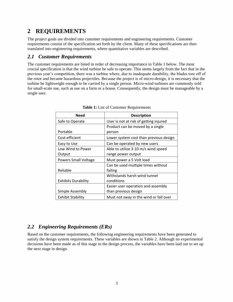
The customer requirements are listed in order of decreasing importance in Table 1 below. The most
crucial specification is that the wind turbine be safe to operate. This stems largely from the fact that in the
previous year’s competition, there was a turbine where, due to inadequate durability, the blades tore off of
the rotor and became hazardous projectiles. Because the project is of micro-design, it is necessary that the
turbine be lightweight enough to be carried by a single person. Micro-wind turbines are commonly sold
for small-scale use, such as use on a farm or a house. Consequently, the design must be manageable by a
single user.
Table 1: List of Customer Requirements
Need Description
Safe to Operate User is not at risk of getting injured
Portable Product can be moved by a single person
Cost-efficient Lower system cost than previous design
Easy to Use Can be operated by new users
Low Wind to Power Output
Able to utilize 3-10 m/s wind speed range power output
Powers Small Voltage Must power a 5 Volt load
Reliable Can be used multiple times without failing
Exhibits Durability Withstands harsh wind tunnel conditions
Simple Assembly Easier user operation and assembly than previous design
Exhibit Stability Must not sway in the wind or fall over
2.2 Engineering Requirements (ERs)
Based on the customer requirements, the following engineering requirements have been generated to
satisfy the design system requirements. These variables are shown in Table 2. Although no experimental
decisions have been made as of this stage in the design process, the variables have been laid out to set up
the next stage in design.
4
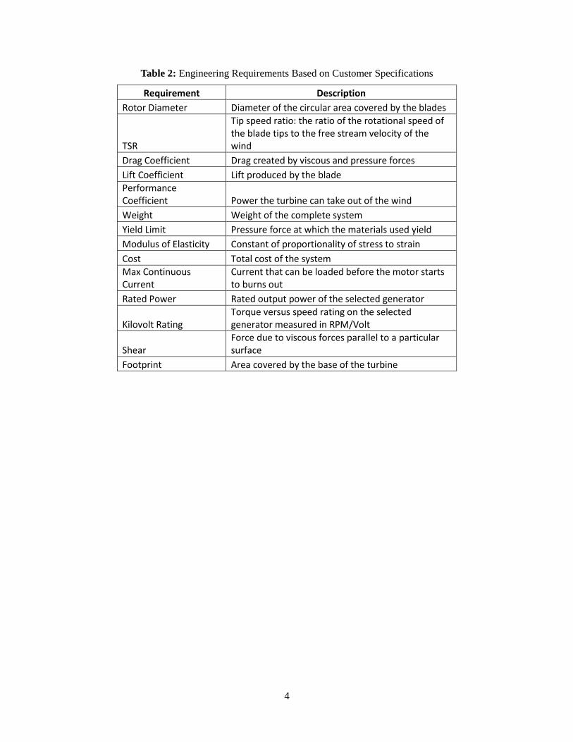
Table 2: Engineering Requirements Based on Customer Specifications
Requirement Description
Rotor Diameter Diameter of the circular area covered by the blades
TSR
Tip speed ratio: the ratio of the rotational speed of the blade tips to the free stream velocity of the wind
Drag Coefficient Drag created by viscous and pressure forces
Lift Coefficient Lift produced by the blade
Performance Coefficient Power the turbine can take out of the wind
Weight Weight of the complete system
Yield Limit Pressure force at which the materials used yield
Modulus of Elasticity Constant of proportionality of stress to strain
Cost Total cost of the system
Max Continuous Current
Current that can be loaded before the motor starts to burns out
Rated Power Rated output power of the selected generator
Kilovolt Rating Torque versus speed rating on the selected generator measured in RPM/Volt
Shear Force due to viscous forces parallel to a particular surface
Footprint Area covered by the base of the turbine
5
2.3 Testing Procedures
2.3.1 T1
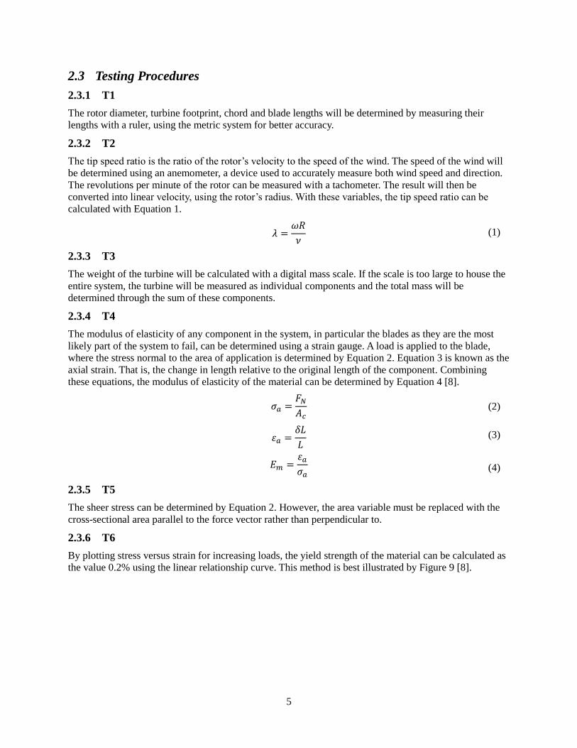
The rotor diameter, turbine footprint, chord and blade lengths will be determined by measuring their
lengths with a ruler, using the metric system for better accuracy.
2.3.2 T2
The tip speed ratio is the ratio of the rotor’s velocity to the speed of the wind. The speed of the wind will
be determined using an anemometer, a device used to accurately measure both wind speed and direction.
The revolutions per minute of the rotor can be measured with a tachometer. The result will then be
converted into linear velocity, using the rotor’s radius. With these variables, the tip speed ratio can be
calculated with Equation 1.
2.3.3 T3
The weight of the turbine will be calculated with a digital mass scale. If the scale is too large to house the
entire system, the turbine will be measured as individual components and the total mass will be
determined through the sum of these components.
2.3.4 T4
The modulus of elasticity of any component in the system, in particular the blades as they are the most
likely part of the system to fail, can be determined using a strain gauge. A load is applied to the blade,
where the stress normal to the area of application is determined by Equation 2. Equation 3 is known as the
axial strain. That is, the change in length relative to the original length of the component. Combining
these equations, the modulus of elasticity of the material can be determined by Equation 4 [8].
2.3.5 T5
The sheer stress can be determined by Equation 2. However, the area variable must be replaced with the
cross-sectional area parallel to the force vector rather than perpendicular to.
2.3.6 T6
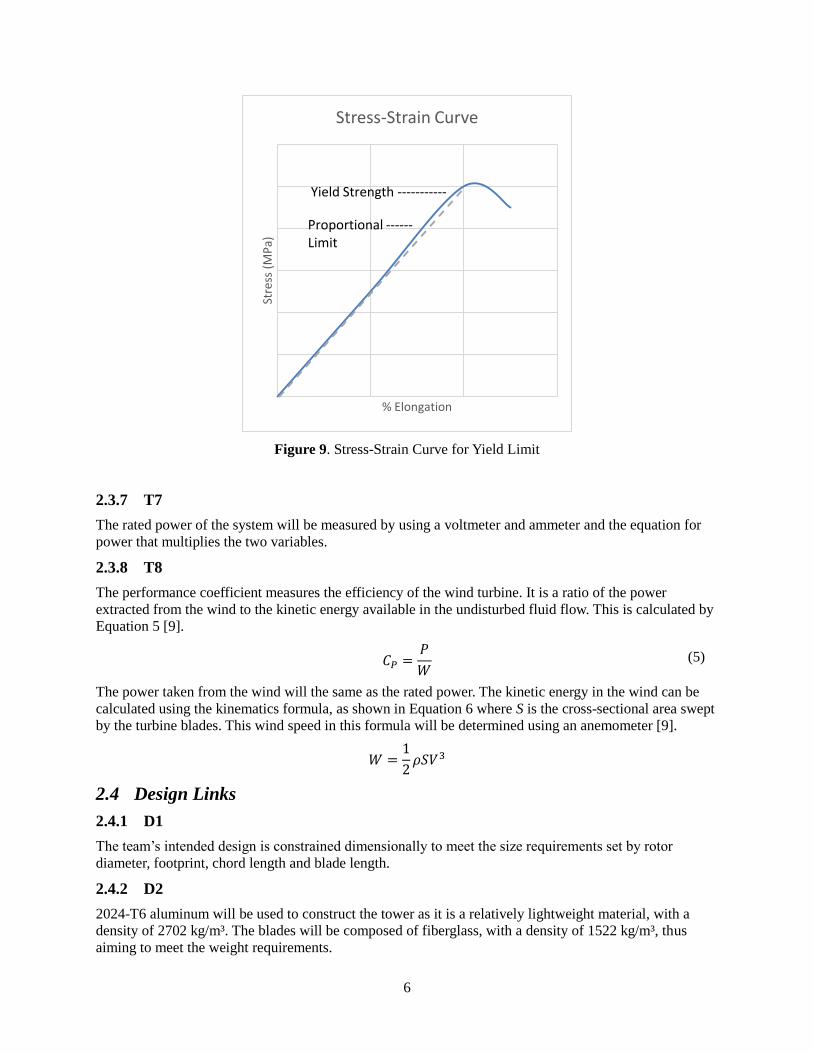
By plotting stress versus strain for increasing loads, the yield strength of the material can be calculated as
the value 0.2% using the linear relationship curve. This method is best illustrated by Figure 9 [8].
(1)
(2)
(3)
(4)
6
Figure 9. Stress-Strain Curve for Yield Limit
2.3.7 T7
The rated power of the system will be measured by using a voltmeter and ammeter and the equation for
power that multiplies the two variables.
2.3.8 T8
The performance coefficient measures the efficiency of the wind turbine. It is a ratio of the power
extracted from the wind to the kinetic energy available in the undisturbed fluid flow. This is calculated by
Equation 5 [9].
The power taken from the wind will the same as the rated power. The kinetic energy in the wind can be
calculated using the kinematics formula, as shown in Equation 6 where S is the cross-sectional area swept
by the turbine blades. This wind speed in this formula will be determined using an anemometer [9].
2.4 Design Links
2.4.1 D1
The team’s intended design is constrained dimensionally to meet the size requirements set by rotor
diameter, footprint, chord length and blade length.
2.4.2 D2
2024-T6 aluminum will be used to construct the tower as it is a relatively lightweight material, with a
density of 2702 kg/m³. The blades will be composed of fiberglass, with a density of 1522 kg/m³, thus
aiming to meet the weight requirements.
Stre
ss (
MP
a)
% Elongation
Stress-Strain Curve
Yield Strength -----------
Proportional ------ Limit
(5)
7
2.4.3 D3
Using fiberglass for the blades simultaneously accomplishes the task of maintaining a high yield strength.
The yield limit for fiberglass is approximately 206 MPa [10]. The modulus of elasticity for fiberglass is
5.5 GPa. The testing procedure outlined in the previous section will determine the true value of the
material’s modulus of elasticity. If the material exceeds the tolerance outlined in the House of Quality, a
new material, or a different composition of fiberglass, will be tested.
2.4.4 D4
The sheer strength of fiberglass is approximately 31 MPa. It is evident that because modulus of elasticity,
sheer strength and yield strength are related, a material that balances these three variables must be
determined through composition testing.
2.4.5 D5
The tip speed ratio is largely dependent on the shape of the blades. The blades will be designed using a
program called Q-Blade. This program calculates the coefficient of performance for a given blade shape
and Reynolds number. The team will achieve the values outlined in the House of Quality by manipulating
the program until a desirable coefficient of performance is achieved at a tip speed ratio of 7.

8
2.5 House of Quality
To better understand the relationship between the customer and engineering requirements, a House of
Quality has been implemented. The figure below rates the customer requirements according to importance
then presents the variables that would be used to satisfy these requirements.
Customer Requirements Weighting
Ro
tor
Dia
me
ter
(m)
Tip
Sp
eed
Rat
io
Wei
ght
(kg)
Yie
ld L
imit
(M
Pa)
Mo
du
lus
of
Elas
tici
ty (
GP
a)
Rat
ed P
ow
er
(V)
Shea
r (M
Pa)
Foo
tpri
nt
(m)
Pe
rfo
rman
ce C
oef
fici
en
t
Ch
ord
Len
gth
(m
)
Bla
de
Len
gth
(m
)
Safe to operate 40 5 10 10 5 5 5
Exhibits durability 40 20 20
Exhibits stability 40 10 10 10 10
Powers a 5V load 40 10 20 10
Low cut in wind speed 40 10 10 10 10
Must be reliable 30 10 10 10
Must be portable 20 10 10
Creative design LTE
Easy to use LTE
Easy to assemble LTE
Target (w/tol)
D ≤
0.4
5m
6.5
± 5
9.1
± 2
.3kg
95
± 1
0M
Pa
3 ±
1G
Pa
5 ±
0.2
V
70
± 1
0M
Pa
0.3
± 0
.05
m
0.4
5 ±
0.0
5
0.0
6-0
.00
5 ±
0.0
01
m
0.1
9 ±
0.0
2m
Testing Procedure T1 T2 T3 T6 T4 T7 T5 T1 T8 T1 T1
Design Link D1 D5 D2 D3 D3 - D4 D1 D5 D1 D1
Figure 1: Relationship Between Customer and Engineering Requirements
9
3 EXISTING DESIGNS
In order to better approach this project, state of the art research has been conducted. This section contains
three existing designs that were relevant to our customer requirements. Section 4.1 discusses the sources
used and how they were chosen. Section 4.2 introduces the three systems and how they meet the same
requirements as this project. Section 4.3 discusses each design at the subsystem level. Three design
innovations used in benchmarking and idea generation are: the Dragonfly Wind Turbine, Robert Howell’s
design and the MagLev Wind Turbine.
3.1 Design Research
The major design research resources used are Professor David Willy and “Wind Energy Explained.” The
remaining sources, a combination of journals and open source websites are cited throughout the report as
relevant. The three key features that make up a turbine are blades, a nacelle and a yawing system. The
team has analyzed three designs in particular that will be discussed in the subsequent sections. It is
notable that yawing systems are not discussed in length as they are considered LTEs.
3.2 System Level
In Sections 4.2.1 through 4.2.3, the key features of the three designs considered will be discussed in
detail. Mainly, what makes these systems efficient wind turbines and how do they apply to our team’s
intended design.
3.2.1 Dragonfly Wind Turbine
The dragonfly turbine, designed by Professor Akira Obata of Nippon Bunri, includes what is known as
dragonfly wings. The key feature of this turbine is that it can operate at speeds as low as 2 m/s, which as
an ideal value for a micro-wind turbine [3].
3.2.2 Robert Howell
Professor Robert Howell of the University of Sheffield designed a VAWT that uses an H rotor. An H rotor
is system of rotating airfoils. It has a wing tip speed ratio (TSR) of 2.2 at a wind velocity of 5.45 m/s,
yielding an efficiency of 0.225. Even at wind speeds as low as 3.16 m/s, the wind turbine has an
efficiency of 0.135. [4]
3.2.3 MagLev Wind Turbine
The MagLev wind turbine was designed by NuEnergy Technologies. It is a vertical-axis wind turbine that
operates with a magnetically levitated system. The system is wear-free and has frictionless components,
which is an objective our project should aim for to maximize power production. Traditional wind turbines
tend to wear down easily, causing damage to the system as extensive as the blades ripping off during
operation. For this reason, it is essential we design with durability in mind [5].
3.3 Subsystem Level
In Section 3.3.1, the three designs researched will be broken down into their subparts and discussed in
further detail. The subsystems include blade system, nacelle and yawing system. It is noteworthy that
although the yawing system will be discussed as it applies to each design, yawing systems in general will
be regarded as an LTE for the duration of this report.
3.3.1 Blade System
Of the three designs outlined, the Dragonfly turbine has the most technically and aesthetically impressive
wing design.
10
3.3.1.1 Dragonfly Wind Turbine
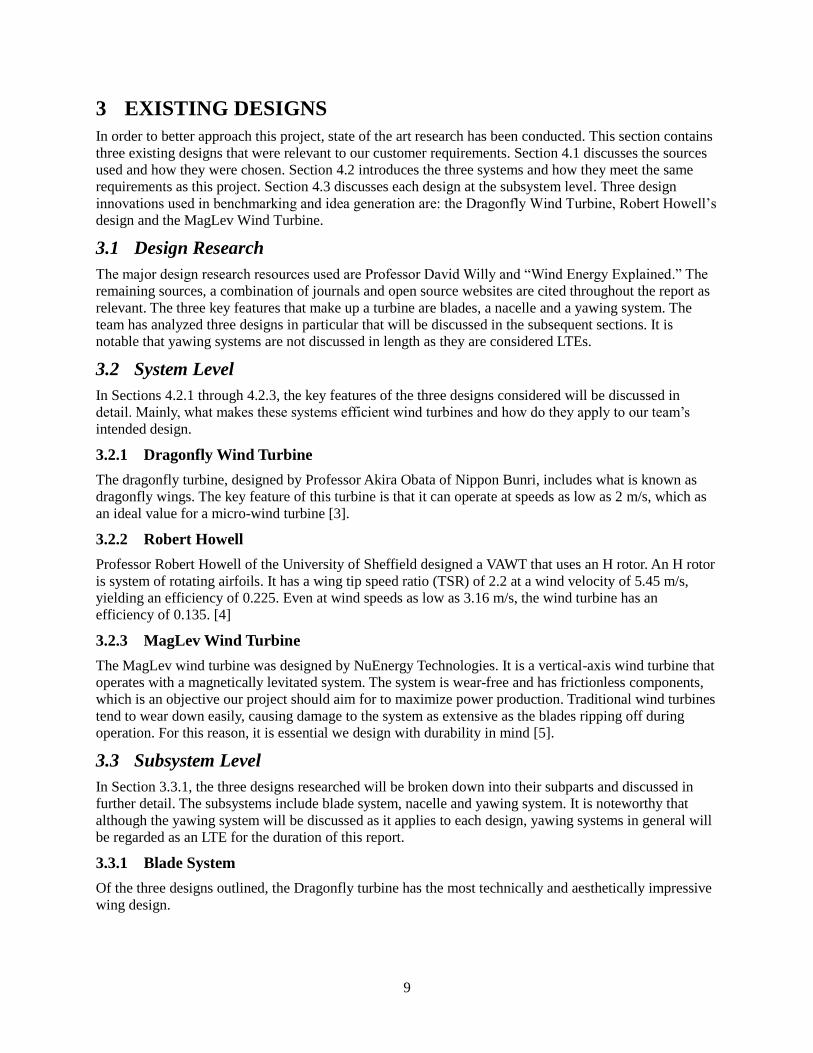
The highlighting component of the Dragonfly wind turbine are the dragonfly-inspired blades, as shown in
Figure 2. The shape of the blades and composition of carbon and polycarbonate materials allow it to
operate at wind speeds as low as 2 m/s. Technical advantage aside, the transparent panels in the blade are
designed to show the carbon structure inside [3].
Figure 2: Dragonfly Wind Turbine Profile [3]
3.3.1.2 Robert Howell
The NACA022 profile is integral to Howell’s design. It is based on a thickness of 22 mm and a resulting
chord of 100 mm. The chord is the imaginary line linking the trailing and leading edges of an airfoil. The
height is approximately 400 mm. The blades have an aspect ratio of 4. The turbine has a solidity of 1.0 for
three-bladed design and 0.67 for two-bladed design. Solidity is the percentage of a rotor’s circumference
that contains material rather than air. These blades are constructed using a CNC milling machine from a
high-density foam. It is necessary that these blades maintain a high thickness to withstand the high
centrifugal bending forces due to the rapid rotation of the turbine [4].
3.3.1.3 MagLev Wind Turbine
The vertical-alignment of the blades in the Maglev turbine allow it to capture greater surface areas during
startup. Unfortunately, this design ultimately results in an increased drag coefficient. The system using
magnetic suspension to remove friction coefficients throughout the system. In order to be effective at a
high scale size, the system must be constructed of a low-density material.
11
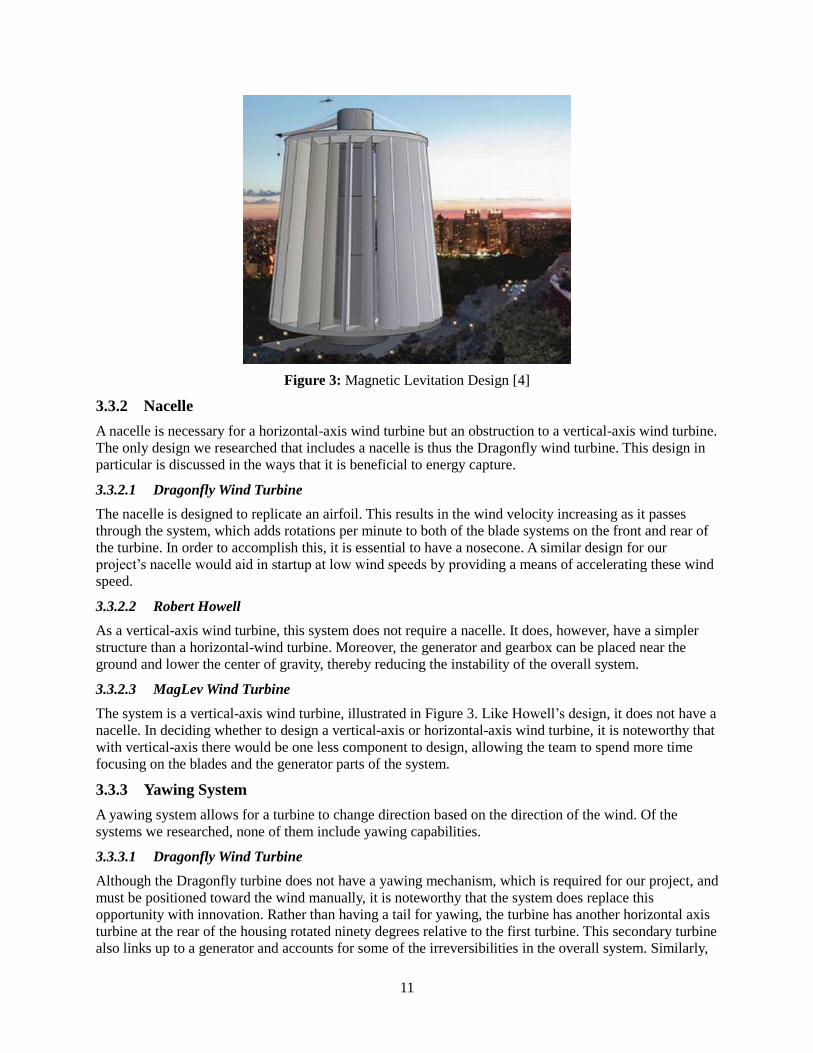
Figure 3: Magnetic Levitation Design [4]
3.3.2 Nacelle
A nacelle is necessary for a horizontal-axis wind turbine but an obstruction to a vertical-axis wind turbine.
The only design we researched that includes a nacelle is thus the Dragonfly wind turbine. This design in
particular is discussed in the ways that it is beneficial to energy capture.
3.3.2.1 Dragonfly Wind Turbine
The nacelle is designed to replicate an airfoil. This results in the wind velocity increasing as it passes
through the system, which adds rotations per minute to both of the blade systems on the front and rear of
the turbine. In order to accomplish this, it is essential to have a nosecone. A similar design for our
project’s nacelle would aid in startup at low wind speeds by providing a means of accelerating these wind
speed.
3.3.2.2 Robert Howell
As a vertical-axis wind turbine, this system does not require a nacelle. It does, however, have a simpler
structure than a horizontal-wind turbine. Moreover, the generator and gearbox can be placed near the
ground and lower the center of gravity, thereby reducing the instability of the overall system.
3.3.2.3 MagLev Wind Turbine
The system is a vertical-axis wind turbine, illustrated in Figure 3. Like Howell’s design, it does not have a
nacelle. In deciding whether to design a vertical-axis or horizontal-axis wind turbine, it is noteworthy that
with vertical-axis there would be one less component to design, allowing the team to spend more time
focusing on the blades and the generator parts of the system.
3.3.3 Yawing System
A yawing system allows for a turbine to change direction based on the direction of the wind. Of the
systems we researched, none of them include yawing capabilities.
3.3.3.1 Dragonfly Wind Turbine
Although the Dragonfly turbine does not have a yawing mechanism, which is required for our project, and
must be positioned toward the wind manually, it is noteworthy that the system does replace this
opportunity with innovation. Rather than having a tail for yawing, the turbine has another horizontal axis
turbine at the rear of the housing rotated ninety degrees relative to the first turbine. This secondary turbine
also links up to a generator and accounts for some of the irreversibilities in the overall system. Similarly,
12
our system can be designed to try and account for as many irreversibilities as possible and maximize
power production at low wind speeds.
3.3.3.2 Robert Howell
The system is a vertical-axis wind turbine and thus does not need to yaw but rather benefits from
capturing the wind at various directions. [2]
3.3.3.3 MagLev Wind Turbine
Because the system is a vertical-axis wind turbine, the system does not need to yaw as it captures wind for
all 360 degrees of rotation. [3]
13
4 DESIGNS CONSIDERED
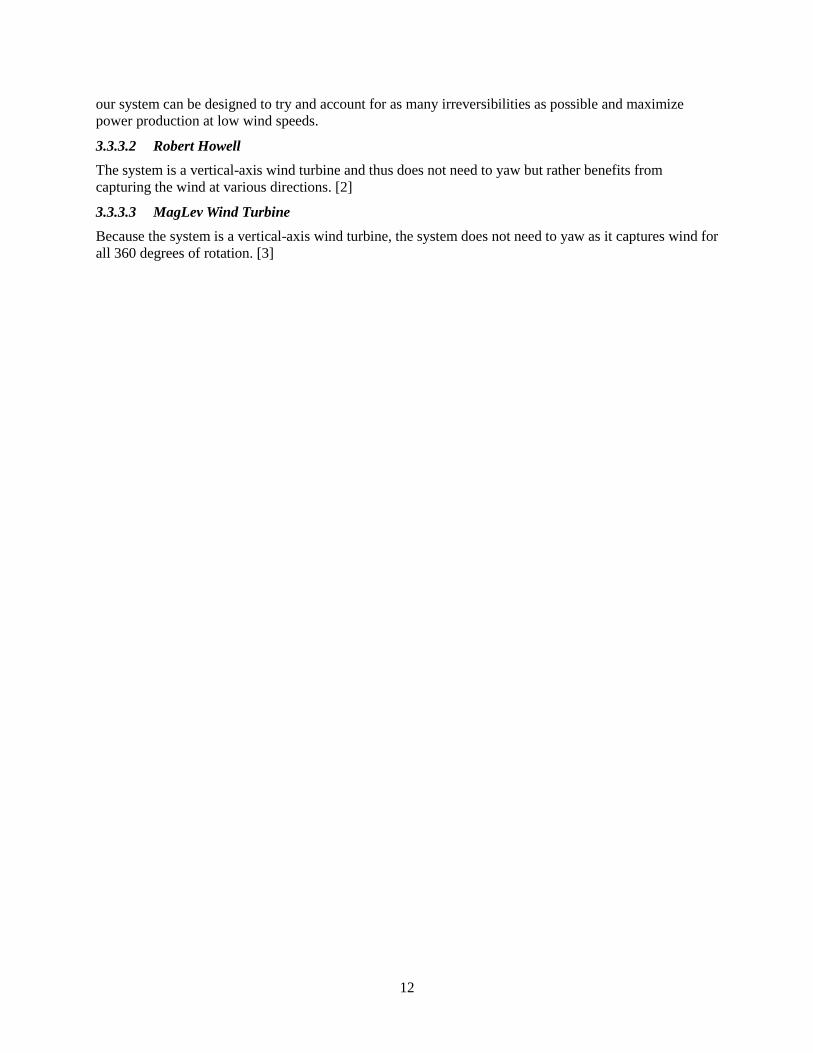
Three design innovations used in benchmarking and idea generation are the Dragonfly wind turbine,
Robert Howell’s design and the Magnetic Levitation turbine. From these designs, two major ideas were
considered: magnetic levitation and nature-inspired blades. Further concept generation, while adhering to
the customer and engineering requirements, resulted in seven additional ideas. These design elements are
outlined in Table 3.
By relating each idea to how well they meet the engineering requirements, the team determined which
ideas were the most promising. The five best designs scored high on the Pugh chart, meeting safety
requirements, power efficiency requirements and low cut-in wind speeds theoretically. These designs are
analyzed in detail in the following sections.
Table 3: Pugh Chart
Pugh Chart
We
igh
t 3-Bladed Turbine
Nacelle Cut-out
3-Bladed Nozzle-Diffuser
H-Rotor with
Adjacent Rotation
Peregrine Turbine
with Airfoil
Nacelle
Horizontal Axis Blade
Turbine
Vortex Turbine
Basic H-
Rotor
Magnetically Assisted Turbine
Whale Tail
Blades
Safe to Operate
1 0 + + 0 0 - + 0 0 0
Durability 1 0 - 0 - 0 0 - 0 + 0
Power Efficiency
2 + 0 + + + 0 + - 0 +
Stability 1 0 0 + 0 0 + - 0 0 0
Power 5V 2 0 + 0 0 + + + + + +
Low Cut-in Speed
2 + + 0 + + + + + + +
Reliability 1 0 + - 0 + + + 0 + 0
Portability 1 0 0 0 0 0 - 0 0 0 0
Ease of Use
1 0 0 + + 0 - - 0 0 0
Low Cost 1 - 0 - - + - - - - -
Easy Assembly
1 + - - + - + - - - +
Sum (+) 4 6 5 5 8 7 8 4 6 7
Sum (-) 1 2 3 2 1 4 5 4 2 1
Total 3 4 2 3 7 3 3 0 4 6
14
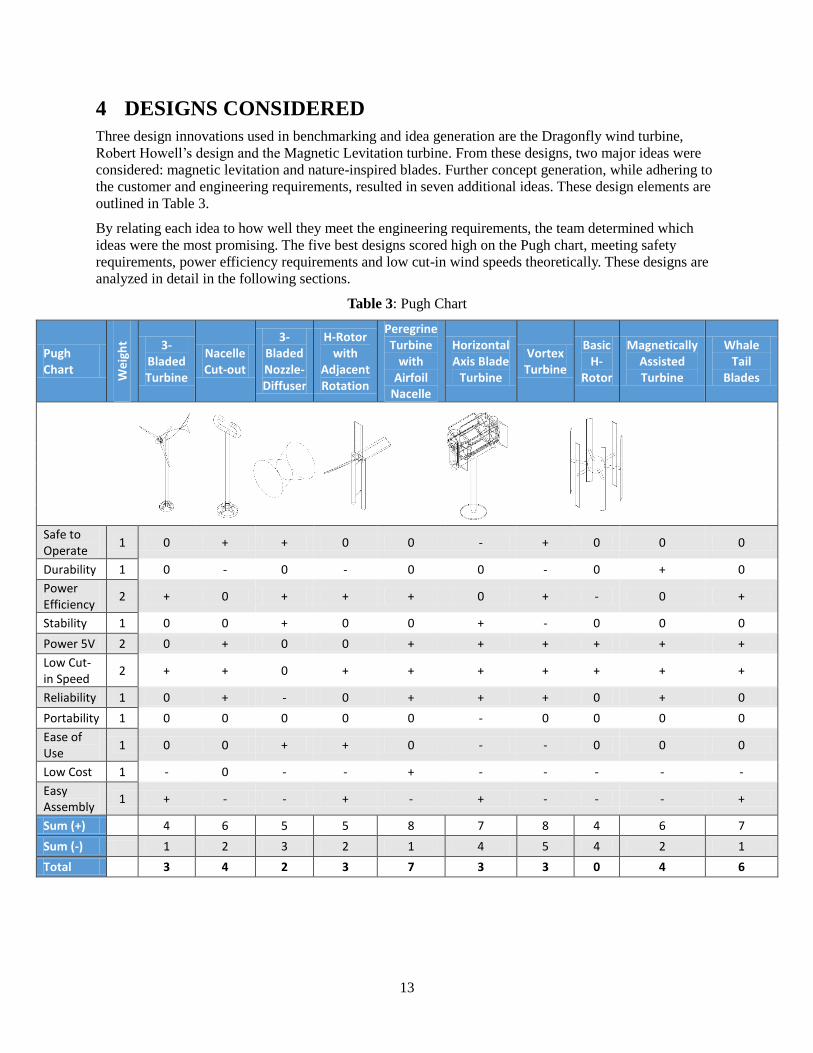
4.1 Nozzle-Diffuser
A nozzle-diffuser encases the three-bladed system. This accelerates the wind speeds across the blades.
Higher wind speeds will yield a lower cut-in minimum. The nacelle for this design will essentially be the
nozzle-diffuser, as illustrated in Figure 4. If the diffuser is larger than the nozzle, it will function as a tail
and allow the system to yaw. The nozzle-diffuser would be connected to a standard tower.
Advantages: The nozzle-diffuser would yield a low cut-in wind speeds
Disadvantages: There would be a steep additional cost of materials to build nozzle-diffuser.
Figure 4: Nozzle-Diffuser Profile
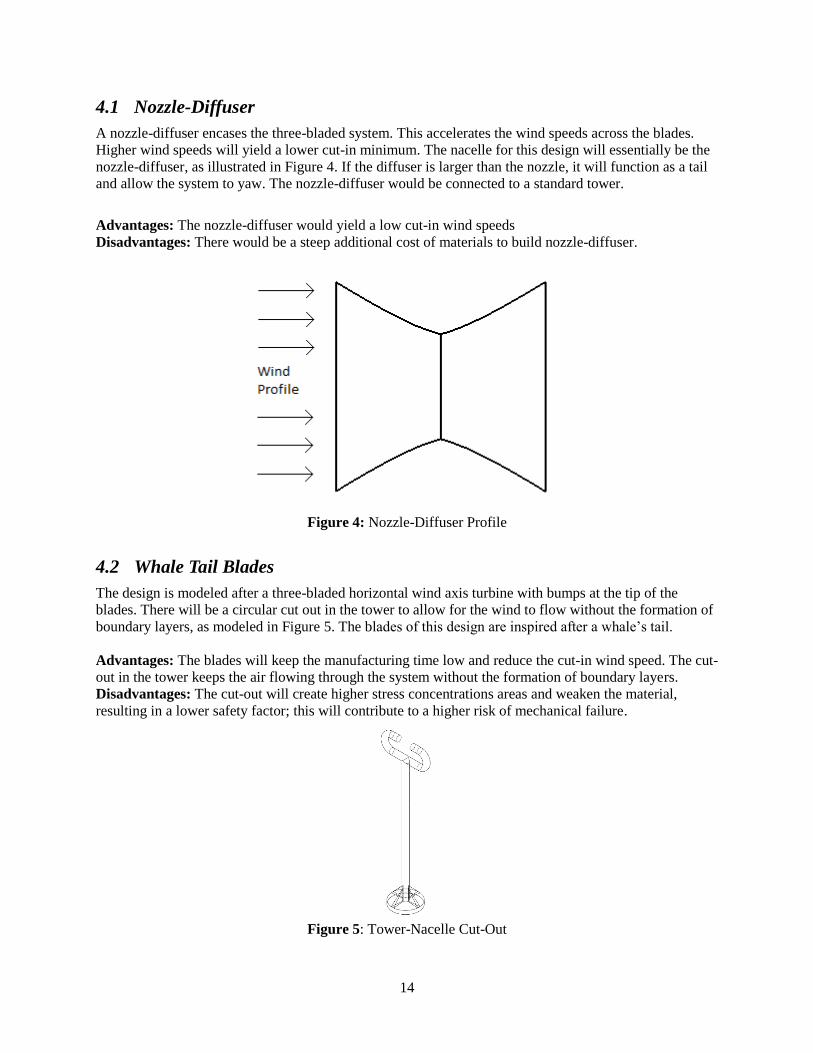
4.2 Whale Tail Blades
The design is modeled after a three-bladed horizontal wind axis turbine with bumps at the tip of the
blades. There will be a circular cut out in the tower to allow for the wind to flow without the formation of
boundary layers, as modeled in Figure 5. The blades of this design are inspired after a whale’s tail.
Advantages: The blades will keep the manufacturing time low and reduce the cut-in wind speed. The cut-
out in the tower keeps the air flowing through the system without the formation of boundary layers.
Disadvantages: The cut-out will create higher stress concentrations areas and weaken the material,
resulting in a lower safety factor; this will contribute to a higher risk of mechanical failure.
Figure 5: Tower-Nacelle Cut-Out
15
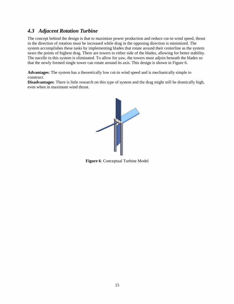
4.3 Adjacent Rotation Turbine
The concept behind the design is that to maximize power production and reduce cut-in wind speed, thrust
in the direction of rotation must be increased while drag in the opposing direction is minimized. The
system accomplishes these tasks by implementing blades that rotate around their centerline as the system
nears the points of highest drag. There are towers to either side of the blades, allowing for better stability.
The nacelle in this system is eliminated. To allow for yaw, the towers must adjoin beneath the blades so
that the newly formed single tower can rotate around its axis. This design is shown in Figure 6.
Advantages: The system has a theoretically low cut-in wind speed and is mechanically simple to
construct.
Disadvantages: There is little research on this type of system and the drag might still be drastically high,
even when in maximum wind thrust.
Figure 6: Conceptual Turbine Model
16
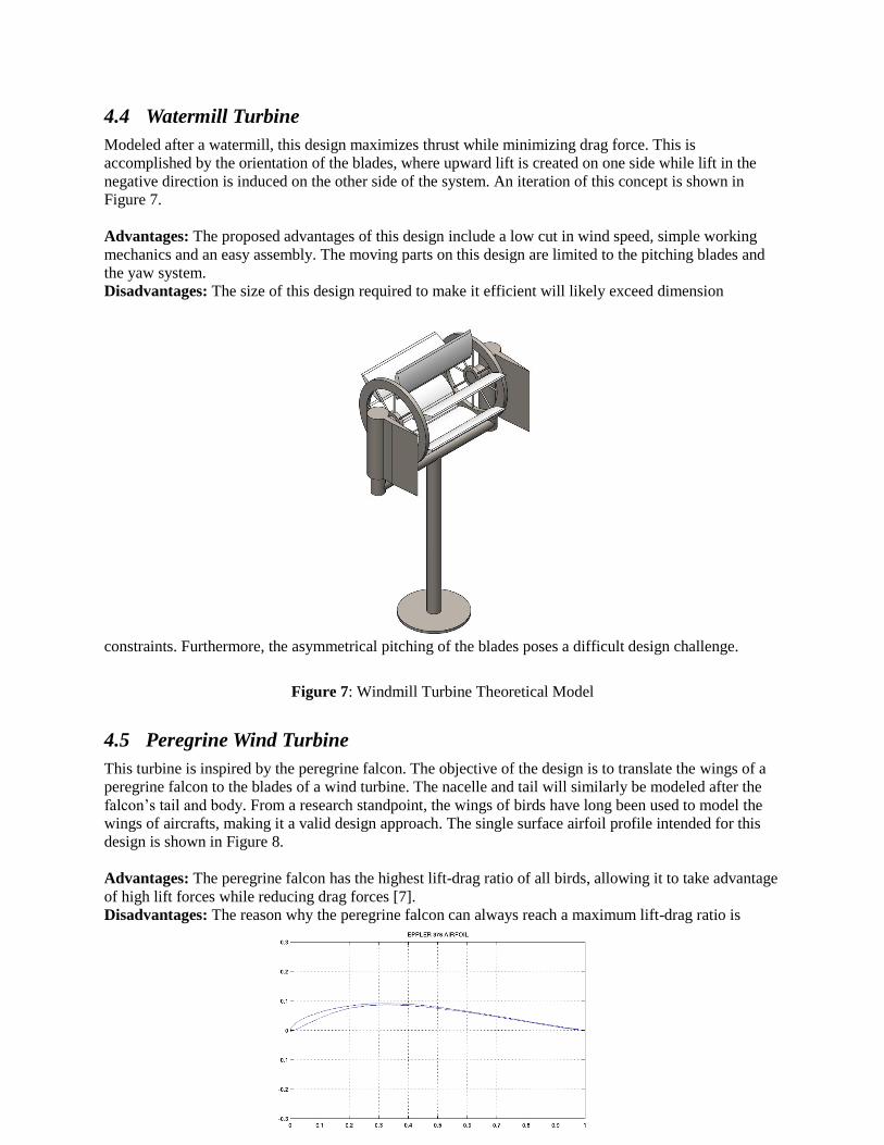
4.4 Watermill Turbine
Modeled after a watermill, this design maximizes thrust while minimizing drag force. This is
accomplished by the orientation of the blades, where upward lift is created on one side while lift in the
negative direction is induced on the other side of the system. An iteration of this concept is shown in
Figure 7.
Advantages: The proposed advantages of this design include a low cut in wind speed, simple working
mechanics and an easy assembly. The moving parts on this design are limited to the pitching blades and
the yaw system.
Disadvantages: The size of this design required to make it efficient will likely exceed dimension
constraints. Furthermore, the asymmetrical pitching of the blades poses a difficult design challenge.
Figure 7: Windmill Turbine Theoretical Model
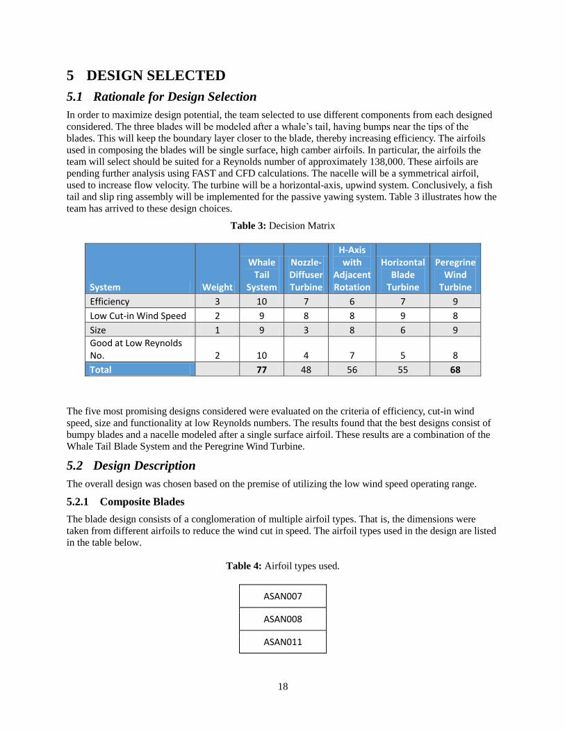
4.5 Peregrine Wind Turbine
This turbine is inspired by the peregrine falcon. The objective of the design is to translate the wings of a
peregrine falcon to the blades of a wind turbine. The nacelle and tail will similarly be modeled after the
falcon’s tail and body. From a research standpoint, the wings of birds have long been used to model the
wings of aircrafts, making it a valid design approach. The single surface airfoil profile intended for this
design is shown in Figure 8.
Advantages: The peregrine falcon has the highest lift-drag ratio of all birds, allowing it to take advantage
of high lift forces while reducing drag forces [7].
Disadvantages: The reason why the peregrine falcon can always reach a maximum lift-drag ratio is

17
because it can change its wing span at different wing speeds, a task that is difficult to model mechanically
in a small-scale project.
Figure 8: Single Surface Airfoil Thickness
18
5 DESIGN SELECTED
5.1 Rationale for Design Selection
In order to maximize design potential, the team selected to use different components from each designed
considered. The three blades will be modeled after a whale’s tail, having bumps near the tips of the
blades. This will keep the boundary layer closer to the blade, thereby increasing efficiency. The airfoils
used in composing the blades will be single surface, high camber airfoils. In particular, the airfoils the
team will select should be suited for a Reynolds number of approximately 138,000. These airfoils are
pending further analysis using FAST and CFD calculations. The nacelle will be a symmetrical airfoil,
used to increase flow velocity. The turbine will be a horizontal-axis, upwind system. Conclusively, a fish
tail and slip ring assembly will be implemented for the passive yawing system. Table 3 illustrates how the
team has arrived to these design choices.
Table 3: Decision Matrix
System Weight
Whale Tail
System
Nozzle-Diffuser Turbine
H-Axis with
Adjacent Rotation
Horizontal Blade
Turbine
Peregrine Wind
Turbine
Efficiency 3 10 7 6 7 9
Low Cut-in Wind Speed 2 9 8 8 9 8
Size 1 9 3 8 6 9
Good at Low Reynolds No. 2 10 4 7 5 8
Total 77 48 56 55 68
The five most promising designs considered were evaluated on the criteria of efficiency, cut-in wind
speed, size and functionality at low Reynolds numbers. The results found that the best designs consist of
bumpy blades and a nacelle modeled after a single surface airfoil. These results are a combination of the
Whale Tail Blade System and the Peregrine Wind Turbine.
5.2 Design Description
The overall design was chosen based on the premise of utilizing the low wind speed operating range.
5.2.1 Composite Blades
The blade design consists of a conglomeration of multiple airfoil types. That is, the dimensions were
taken from different airfoils to reduce the wind cut in speed. The airfoil types used in the design are listed
in the table below.
Table 4: Airfoil types used.
ASAN007
ASAN008
ASAN011
19
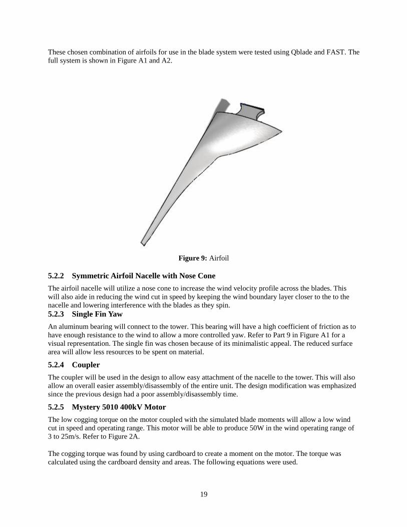
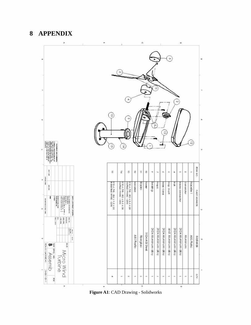
These chosen combination of airfoils for use in the blade system were tested using Qblade and FAST. The
full system is shown in Figure A1 and A2.
Figure 9: Airfoil
5.2.2 Symmetric Airfoil Nacelle with Nose Cone
The airfoil nacelle will utilize a nose cone to increase the wind velocity profile across the blades. This
will also aide in reducing the wind cut in speed by keeping the wind boundary layer closer to the to the
nacelle and lowering interference with the blades as they spin.
5.2.3 Single Fin Yaw
An aluminum bearing will connect to the tower. This bearing will have a high coefficient of friction as to
have enough resistance to the wind to allow a more controlled yaw. Refer to Part 9 in Figure A1 for a
visual representation. The single fin was chosen because of its minimalistic appeal. The reduced surface
area will allow less resources to be spent on material.
5.2.4 Coupler
The coupler will be used in the design to allow easy attachment of the nacelle to the tower. This will also
allow an overall easier assembly/disassembly of the entire unit. The design modification was emphasized
since the previous design had a poor assembly/disassembly time.
5.2.5 Mystery 5010 400kV Motor
The low cogging torque on the motor coupled with the simulated blade moments will allow a low wind
cut in speed and operating range. This motor will be able to produce 50W in the wind operating range of
3 to 25m/s. Refer to Figure 2A.
The cogging torque was found by using cardboard to create a moment on the motor. The torque was
calculated using the cardboard density and areas. The following equations were used.
20
m=V
Where,
M = mass,
= density,
V= volume.
F=mg
Where,
M = mass(kg),
F = force(N)
g=9.8(m/s^2).
M=Fr
Where,
M = moment(N*m),
F = force(N),
R = radius(m).
The resulting minimum torque that was found was .035 N-m. With the aforementioned calculation for the
blade the, minimum torque requirement is satisfied.
5.2.6 Tower & Base
When testing the design in a wind tunnel, the design has to be attachable to the base on ground in the
wind tunnel. Thus, the tower has a design that will allow for ease of attaching and securing the wind
turbine to the ground in the wind tunnel.
5.2.7 Hub & Propeller Shaft
The hub is designed to secure the blades onto the nacelle. Furthermore, rotational energy is transferred
from the blades through the propeller shaft to the generator. The connection is accomplished through
direct drive to eliminate the need for a gearbox.

21
6 IMPLEMENTATION
In order to successfully build the design, the blades have to be working as planned. Prototypes of the
blades will be made in 3D printers. Using the wind-tunnel located in 98C building, the prototypes can be
tested to failure. A simulation can also be created using computational fluid dynamics (CFD) software to
simulate the flow of air along the blades. The next step is manufacturing the hub and molds for the blades.
Two molds will be needed, which will be made out of graphite. One will be for the blades, and the other
is to connect all blades together. The molds will be made in the machine shop with the supervision and
help of Dr. Tester. The hub will be manually fabricated in the machine shop as well. After these
components are ready, the nacelle will be machined in the shop using a CNC machine. The bearing will
also be machined with the same machine.
The mystery 5010- 400kv generator will be purchased online. A corresponding propeller shaft will also be
ordered. The tower will be fabricated using machine shop with the help of the TA’s there.
The following bill of materials illustrates the quantity and the material needed to build the design. Most of
the parts will be manufactured in the machine shop in Northern Arizona University. The materials needed
to make the parts will be purchased.
The cost of 2024 Aluminum Alloy was partitioned evenly for the six parts of the system. This represents
that these parts will be constructed from a single large sheep of 2024 Aluminum Alloy.
Table 5: Bill of Materials
Parts Materials Vendor Quantity Cost ($)
Nacelle 1 ABS Plastic Dr. Tester 1 -
Generator Aluminum California Metal and Supply Inc. 1 24.99
Blade Connector 2024 Aluminum Alloy California Metal and Supply Inc. 1 17.00
Hub 2024 Aluminum Alloy California Metal and Supply Inc. 1 17.00
Prop Shaft 2024 Aluminum Alloy California Metal and Supply Inc. 1 17.00
Nose Cone 2024 Aluminum Alloy California Metal and Supply Inc. 1 17.00
Prop 2 2024 Aluminum Alloy California Metal and Supply Inc. 1 17.00
Bearing 2024 Aluminum Alloy California Metal and Supply Inc. 1 17.00
Tower 1024 AISI Steel Aircraft Materials 1 2.44
Blades Fiberglass U.S. Composites 3 15.79
Nacelle 2 ABS Plastic Dr. Tester 1 -
B18.6.7M - M3 x 0.5 x 20 Slotted PHMS --20N
Cast Iron Blacksmith Bolt & Rivet Supply 5 4.00
B18.6.7M - M3 x 0.5 x 20 Slotted PHMS --30N
Cast Iron Blacksmith Bolt & Rivet Supply 1 4.00
B18.6.7M - M3 x 0.5 x 20 Indented HFMS --25N
Cast Iron Blacksmith Bolt & Rivet Supply 4 4.00
Total 23 $185.22
22
7 REFERENCES
[1]. Fingersh, L. J., Hand, M. M., & Laxson, A. S. (2006). Wind turbine design cost and scaling
model. Golden, CO: National Renewable Energy Laboratory.
[2]. Peacock, A. D., Jenkins, D., Ahadzi, M., Berry, A., & Turan, S. (2008). Micro wind turbines in the
UK domestic sector. Energy and Buildings, 40(7), 1324-1333.
[3]. Azzarello, Nina. (2013) Dragonfly Invisible Wind Turbine. [Online]. Available:
http://www.designboom.com/technology/dragonfly-invisible-wind-turbine-designed-by-renzo-
piano-10-23-2013/
[4]. Howell, Robert. (n.d.) Wind Tunnel and Numerical Study of a Small Vertical Axis Wind Turbine.
[Online]. Available: www.elsevier.come/locate/renene
[5]. NuEnergy Technologies. (2011) MagLev Wind Turbine. [Online]. Available:
www.nuenergytech.com
[6]. Manwell, J. F., and J. G. McGowan. Wind Energy Explained Theory, Design and Application.
Chichester: Wiley, 2002. Print.
[7]. Tucker, V. A., & Parrott, G. C. (1970). Aerodynamics of gliding flight in a falcon and other
birds. Journal of Experimental Biology, 52(2), 345-367.
[8]. Figliola, Richard S. (2011). Strain Measurement. Theory and Design for Mechanical
Measurements, (5).
[9]. Ragheb, M., & Ragheb, A. M. (2011). Wind turbines theory-the betz equation and optimal rotor
tip speed ratio. Fundamental and Advanced Topics in Wind Power, (2), 19-38.
[10]. Incropera, Frank P. (2011). Fundamentals of Heat and Mass Transfer, (7).
23
8 APPENDIX
Figure A1: CAD Drawing - Solidworks
24
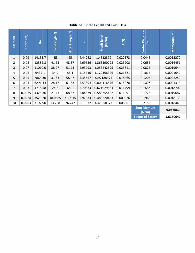
Table A1: Chord Length and Twist Data
Ele
men
t
Ch
ord
(m
)
Re
Twis
t an
gle(
°)
Att
ack
angl
e(°)
Cl
F(u
nit
len
gth
)(
N/m
)
F(N
)
Cen
ter
Dis
tan
ce
(m)
Mo
me
nt(
N-m
)
1 0.09 14155.7 45 45 4.44288 1.4512399 0.027573 0.0445 0.0012270
2 0.08 12582.8 41.63 48.37 4.69636 1.363590728 0.025908 0.0635 0.0016451
3 0.07 11010.0 38.27 51.73 4.93293 1.253242595 0.023811 0.0825 0.0019644
4 0.06 9437.1 34.9 55.1 5.15316 1.122166326 0.021321 0.1015 0.0021640
5 0.05 7864.30 31.53 58.47 5.35557 0.97186974 0.018465 0.1205 0.0022250
6 0.04 6291.44 28.17 61.83 5.53894 0.804116576 0.015278 0.1395 0.0021313
7 0.03 4718.58 24.8 65.2 5.70373 0.621029684 0.011799 0.1585 0.0018702
8 0.0275 4325.36 21.43 68.57 5.84879 0.583755422 0.011091 0.1775 0.0019687
9 0.0224 3523.20 18.0685 71.9315 5.97333 0.485620483 0.009226 0.1965 0.0018130
10 0.0203 3192.90 13.258 76.742 6.11572 0.45058377 0.008561 0.2155 0.0018449
Sum Moment (N*m)
0.056562
Factor of Safety 1.6160642
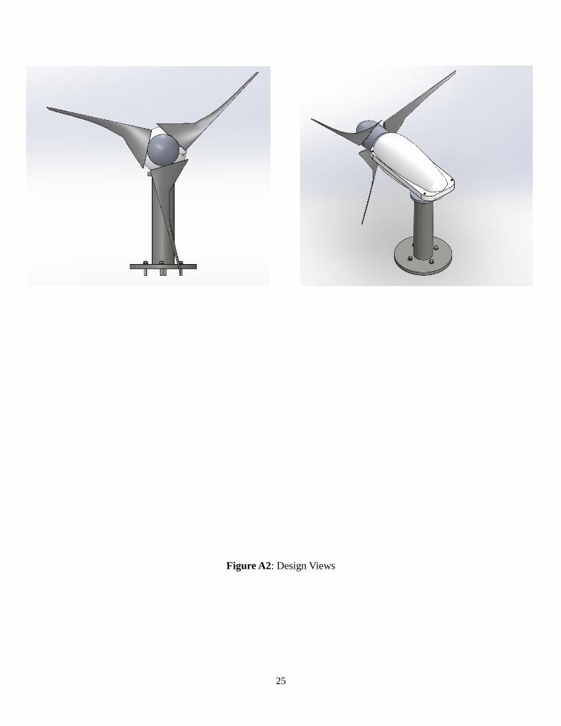
25
Figure A2: Design Views
![arXiv:1605.03621v1 [cs.CV] 11 May 2016 · Sriram Sivaramakrishnan Cornell University Ashok Veeraraghavan Rice University Alyosha Molnar Cornell University Abstract ... arXiv:1605.03621v1](https://img.pdfslide.us/doc/110x75/5fa07c7d849c660cbd4c6347/arxiv160503621v1-cscv-11-may-2016-sriram-sivaramakrishnan-cornell-university.jpg)


![[77b] Herrera, Vielma, Ugel, Alfaro, Barbat, Pujades, 2013](https://img.pdfslide.us/doc/110x75/577cd0d51a28ab9e789329e8/77b-herrera-vielma-ugel-alfaro-barbat-pujades-2013.jpg)