Embed Size (px)
Citation preview

Paul DayDepartment of Mechanical Engineering,
Stanford University,Stanford, CA 94305;
and Los Alamos National Labs,Los Alamos, NM 87544
e-mail: [email protected]
Eric V. EasonDepartment of Applied Physics,
Stanford University,Stanford, CA 94305
e-mail: [email protected]
Noe Esparzae-mail: [email protected]
David Christensene-mail: [email protected]
Mark Cutkoskye-mail: [email protected]
Department of Mechanical Engineering,Stanford University,Stanford, CA 94305
Micro-Wedge Machining for theManufacture of Directional DryAdhesivesDirectional dry adhesives are inspired by animals such as geckos and are a particularlyuseful technology for climbing applications. Previously, they have generally been man-ufactured using photolithographic processes. This paper presents a micro-machiningprocess that involves making cuts in a soft material using a sharp, lubricated tool tocreate closely spaced negative cavities of a desired shape. The machined materialbecomes a mold into which an elastomer is cast to create the directional adhesive. Thetrajectory of the tool can be varied to avoid plastic flow of the mold material that mayadversely affect adjacent cavities. The relationship between tool trajectory and resultingcavity shape is established through modeling and process characterization experiments.This micro-machining process is much less expensive than previous photolithographicprocesses used to create similar features and allows greater flexibility with respect tothe micro-scale feature geometry, mold size, and mold material. The micro-machiningprocess produces controllable, directional adhesives, where the normal adhesion in-creases with shear loading in a preferred direction. This is verified by multi-axis forcetesting on a flat glass substrate. Upon application of a post-treatment to decrease theroughness of the engaging surfaces of the features after casting, the adhesives signif-icantly outperform comparable directional adhesives made from a photolithographic mold.
Keywords: directional, adhesion, gecko, manufacturing, micro-machining
1 Introduction
Impressive advancements have been made in the field of gecko-inspired fibrillar dry adhesives. Fearing [1] maintains a bibliogra-phy of the manufacturing methods for these adhesives, which in-clude a large range of manufacturing processes. However, the useof such adhesives in applications such as climbing has been muchmore limited, with just a few examples reported [2–8]. It has gen-erally been found that the adhesion levels generated in real-worldclimbing applications are significantly lower than those obtainedusing small samples in bench-top experiments.
One reason for this disparity is that, in addition to conformingto surfaces and generating useful levels of adhesion, the adhesiveshave additional requirements when used for climbing. The first ofthese requirements is controllability, i.e., the adhesives should notbe sticky in the default state and adhere only when it is desirable.In any other case, energy will be wasted as it is expended in attach-ing and detaching the adhesive for each step. Controllability can beachieved by using switchable structures [9,10] or by creating direc-tional adhesive features whose adhesion generation is a function ofapplied shear load [11–24].
The second requirement is durability. The adhesives must un-dergo thousands of attach/detach cycles without significant loss ofadhesive properties and, ideally, should resist fouling and be easyto clean. Durability is also correlated with controllability: gen-tle attach/detach cycles reduce mechanical wear and promote longlife [18].
Among the adhesives that have been applied to climbing robots,micro-wedges [18] are simple and durable structures that have en-abled kilogram-scale robots to climb on glass, plastic, wood pan-eling, painted metal, and similar surfaces. In particular, the 0.8 kgStickybotIII robot climbs using approximately 7 cm2 of adhesiveper foot, and the 4 kg RiSE robot climbs using approximately20 cm2 per foot (both robots have four feet and lift two at atime) [25]. Micro-wedges present a very small real area of con-
40μm
a.
b.
100μm
c.
Fig. 1 SEM micrographs of PDMS directional adhesive fea-tures: (a) unloaded micro-wedges from a photolithographicmold, (b) micro-wedges under shear loading, and (c) micro-wedges from a micro-machined mold.
tact with a surface and generate negligible adhesion when they areunloaded, as in Fig. 1a. However, when loaded in a preferredshear direction, as in Fig. 1b, they bend, creating a larger con-tact area and generating adhesion that is proportional to the shearload. The micro-wedges’ asymmetric taper ensures that the ra-dius of curvature of the surface at the proximal edge of the contactpatch increases with increasing shear load, allowing the tapered fea-tures to outperform features of constant cross-section at high shearloads [26]. Furthermore, they may be easily cleaned using a pieceof sticky tape.
In previous work, micro-wedges were manufactured by castinga polydimethylsiloxane (PDMS) silicone elastomer into molds cre-
Journal of Micro and Nano-Manufacturing 1
ated through a photolithographic process in which SU-8 photoresist(MicroChem Corp.) was subjected to two exposures, one angled,one vertical, through contact masks [18]. The necessity of a thickphoto-resist layer combined with the requirement for high preci-sion alignment of exposures resulted in a time consuming, expen-sive mold fabrication process with relatively low yield.
As an alternative, a mold can be created with a micro-machiningprocess that involves making a pattern of cavities in a mold usinga narrow cutting tool. Machining processes have been used pre-viously to create stamps for soft lithography [27] and syntheticadhesive structures [11, 28] using nano-indenters and AFM tips,but neither fabrication nor testing of macroscopic adhesive arrays(∼ 1 cm2) has been demonstrated and the aspect ratio of the result-ing features has been low.
This paper introduces a micro-machining process that is a hybridof orthogonal machining and wedge indenting. A sharp wedge-shaped tool is moved along an oblique trajectory into a soft moldsurface, producing a wedge-shaped cavity of depth on the order of100 µm. By controlling the tool geometry and trajectory and repeat-ing this operation in a pattern across the mold surface, it is possibleto obtain a dense packing of sharp, wedge-shaped cavities. CastingPDMS into these cavities produces micro-wedge features as seen inFig. 1c. In comparison to photolithography, the method presentedhere is cheaper, faster, and affords greater freedom to control thecavity geometry, which governs adhesive performance.
The main motivation of this research is the need for a practicaladhesive for climbing. The new micro-machined micro-wedges,upon application of a simple post-treatment process, perform sig-nificantly better than photolithographic micro-wedges in adhesivetests. The improvement is chiefly a result of having greater freedomto control the wedge taper and angle of inclination. Arrays of thenew wedges have been produced and tested, with maximum normaladhesion of 38± 2 kPa attained at a shear stress of 49± 1 kPa for anarray of area 1.21 cm2. In addition, the micro-machined wedges re-tain the controllability and durability of photolithographic wedges.
In Sec. 2, a simple model of the micro-machining process is in-troduced to explore the relationships among tool geometry, tool tra-jectory, wedge geometry, and the ability to achieve a dense fea-ture spacing. Section 3 gives details of the adhesive fabricationprocess. In Sec. 4, the model is compared to experimental cuttingforces, process characterization results are presented, and the adhe-sive performance of the new micro-machined adhesives is measuredand compared to the previous generation of photolithographic ad-hesives. These results are discussed in Sec. 5. Section 6 presentsconclusions and possible extensions.
2 ModelingIn order to better understand the mechanics involved, a micro-
machining process may be described using numerical finite-elementmodeling or semi-analytic theoretical models. Theoretical mod-els are mostly applied to ideal rigid-plastic materials and are notas likely to accurately predict the forces and deformations. Con-versely, state of the art numerical models can account for realisticmaterial behavior and friction effects. However, the material prop-erties and tribological behavior of the wax mold material used herehave not been sufficiently well characterized to justify a numericalmodel. Moreover, it is not required to produce a numerical predic-tion of the cutting forces in terms of the cutting parameters (e.g.cutting depth, speed, friction, tool angle, or tip radius) as the forcesare, in any case, quite low.
Instead, it is useful to understand how the cutting parameters andtool geometry affect the deformation behavior. In particular, it isdesirable to produce a tightly packed array of cavities in order toobtain a high density of adhesive features. Accordingly, an im-
Built-upregion
� �
�
�
S.P. Trailingside
Leadingside
�����
����
�
�
�
�
�
��
�� Traj.
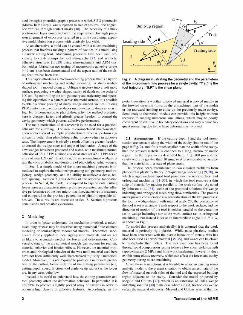
Fig. 2 A diagram illustrating the geometry and the parametersof the micro-machining process for a single cavity. “Traj.” is thetool trajectory; “S.P.” is the shear plane.
portant question is whether displaced material is moved mainly inthe forward direction (towards the unmachined part of the mold)or the rearward (tending to close up the previously made cavity).Semi-analytic theoretical models can provide this insight withoutrecourse to running numerous simulations, which may be poorlyconvergent or sensitive to boundary conditions and may require fre-quent remeshing due to the large deformations involved.
2.1 Assumptions. If the cutting depth t and the tool cross-section are constant along the width of the cavity (into or out of thepage in Fig. 2), and if t is much smaller than the width of the cavity,then the stressed material is confined to a long, narrow prismaticregion. In the experiments described here, t ≤ 100 µm and thecavity width is greater than 10 mm, so it is reasonable to assumethat the material is in a state of plane strain.
The process bears resemblance to two classical problems fromplane-strain plasticity theory: oblique wedge indenting [29, 30], inwhich a rigid wedge-shaped tool penetrates the work surface, andorthogonal machining [31–33], in which the tool removes a thinstrip of material by moving parallel to the work surface. As notedby Johnson et al. [34], some of the proposed solutions for wedgeindenting and orthogonal machining show similarities. The processunder present consideration is a generalization of the two processes:the tool is wedge-shaped with internal angle 2β, the centerline ofthe tool is set at an angle λ with respect to the work surface, and thedirection of motion of the tool is neither parallel to the centerline(as in wedge indenting) nor to the work surface (as in orthogonalmachining), but instead is set at an intermediate angle 0 < θ < λ,as shown in Fig. 2.
To model this process analytically, it is assumed that the workmaterial is perfectly rigid-plastic. While most plasticity studieshave been concerned with the plastic behavior of metals, wax hasalso been used as a work material [35,36], and waxes can be closerto rigid-plastic than metals. The wax used here has been foundthrough axial compression testing to have a low shear yield strength(approximately 2 MPa) and little work hardening; however, it doesexhibit some elastic recovery, which can affect the forces and cavitygeometry during micro-machining.
Given these assumptions, it is feasible to adapt an existing semi-analytic model to the present situation to obtain an estimate of theflow of material on both sides of the tool and the expected buildupregion adjacent to the cavity. Consider the model proposed byMeguid and Collins [37], which is an extension of Hill’s wedgeindenting solution [30] to the case where a rigid, frictionless wedgeenters the material obliquely. Meguid and Collins assume that the
2 Transactions of the ASME
wedge’s direction of motion is along its centerline, but their modelcan be easily modified to allow yawed motion (not parallel to thecenterline) by considering the leading and trailing sides of the toolindependently as in an earlier model by Hill and Lee [38].
2.2 Trajectory Angle. For a perfect rigid-plastic material,the interior shape of the cavity will be identical to the swept volumeof the tool as it moves along its trajectory, which means that anytrajectory angle θ can be chosen from the range λ−β < θ < λ+βwithout affecting the shape of the cavity. However, the extent ofplastic deformation and the amount of buildup occurring on theleading and trailing faces of the tool will vary with θ. If material isdisplaced on both sides of the tool, and the mold cavities are spacedclosely, this flow will result in partial collapse of the previouslyformed cavity.
In order to minimize this effect, the trajectory angle may insteadbe chosen to lie outside this range: θ = λ − β − ε, where ε > 0is a relief angle. This increases the angular width of the cavitiesby the angle ε. A depiction of this geometry can be seen in Fig. 2.The benefit of the relief angle is that the trailing side of the toolshould no longer make contact with the wall of the cavity. As aresult, assuming that the tip of the tool is sufficiently sharp [36,39],the zone of plastic deformation is limited to the leading side of thetool only, and material on the trailing side remains rigid throughoutthe process, theoretically preventing partial collapse of the previouscavity.
2.3 Plastic Region. The Meguid-Collins model predicts twopossibilities for the plastic deformation on the leading side of thetool. In the first case, the plastic region covers the entire area ofdisplaced material, and it is possible to construct a slip-line fieldthroughout this region, similar to the Hill model of wedge indent-ing [30]. In the second case, the plastic region is restricted to asingle shear plane, and elsewhere the material is rigid, in a similarmanner to the Merchant model of orthogonal machining [32, 33].This second case occurs if the trajectory angle is lower than a criti-cal value:
2 tan θ < [1 + tan(α+ θ)]2 (1)
However, this equation is always satisfied if the rake angle α ispositive, as in the present case. Therefore, the model predicts thata single shear plane solution is appropriate on the leading face ofthe tool. The model also provides a prediction of the shear planeangle φ based on an energy-minimization argument similar to theone proposed by Ernst and Merchant [31], but since the model doesnot include friction this prediction is not expected to be accurate.Furthermore, there is doubt about the theoretical and experimentalvalidity of this argument [40–42].
2.4 Cutting Forces. Despite the lack of a trustworthy predic-tion of the shear plane angle φ, the model can be used to make atestable prediction about the cutting forces if φ can be measuredexperimentally. Let the net force applied by the machine to the toolbe denoted by
F = Fxx+ Fyy (2)
and let the total force on the shear plane be denoted by
f = fss+ fnn (3)
as depicted in Fig. 2. In accordance with the model, it is assumedthat the displaced material is limited to a triangular built-up regionalso shown in Fig. 2. As long as there is no contact on the trailingside of the tool, these forces are equal: F = f , and therefore:
fs = Fx(x · s) + Fy(y · s) = Fx cosφ+ Fy sinφ (4)
This relationship does not require any assumptions about theshear plane angle φ or the friction at the leading side of the tool.Finally, according to the theory of perfect rigid-plastic materials inplane strain [40], the shear stress along the shear plane is constantand equal to the shear yield stress k:
fs/A = k (5)
where A is the area of the shear plane.Although the semi-analytic model cannot be expected to produce
a complete prediction of the cutting forces with high accuracy, itproduces a useful prediction about the deformation mode of thematerial (the existence of a shear plane), and it is also useful forunderstanding relationships among λ, β, θ, and φ. This leads tothe expectation that most of the displaced material will be pushedforward if the trajectory angle, θ, is sufficiently small compared tothe angle of the trailing face of the tool, λ− β. In this situation, themodel does produce a testable prediction about the cutting forces(Eqs. 4 and 5).
3 Fabrication
3.1 Materials. The mold fabrication method relies on a fewkey components to be effective. Most important is the wedge-shaped tool, whose shape strongly influences the shape of the re-sulting mold cavities. The tool used here is a PTFE-coated steeldisposable microtome blade (Delaware Diamond Knives D554X).This tool has a fine surface finish, with blade roughness on lengthscales � 1 µm, an internal angle of 2β ≈ 24°, and an edge radiusof less than 0.9 µm (see Sec. 4.1).
The material used for the mold must also be selected for desir-able properties. An ideal material for machining would have a ho-mogeneous composition, a relatively low yield strength, and perfectrigid-plastic behavior to minimize elastic recovery of the machinedregion. As noted by Hirst and Howse [43], rigid-plastic behavioris most likely to occur in indenting processes if the included an-gle of the tool is acute and the ratio of Young’s modulus to yieldstress E/Y is large.
In the present case, a soft, rolled sheet wax (Kindt-Collins MasterRegular Sheet Wax) is used, having a ratio of Young’s modulus toyield stress of approximately E/Y ≈ 110–160. For this value ofE/Y with a tool angle of 24°, according to the results presentedby Hirst and Howse, the deformation behavior is not dominated byelastic effects and rigid-plastic behavior may be possible.
Adhesive wear at the tool-mold interface is undesirable and couldlead to a poor surface finish. However, this is mitigated by lubri-cating the interface. In addition a post-treating process has beendevised to refinish the surfaces entirely (Sec. 3.4). For these rea-sons the tribological properties of the mold material are not a majorconcern for material selection.
3.2 Micro-Machining Method. This micro-machining pro-cess may be performed on a standard CNC milling machine orother machine with positioning control in at least two axes and suf-ficient accuracy. Adhesives have been produced using a tabletopCNC milling machine with 1 µm accuracy (Levil WL400), a larger
Journal of Micro and Nano-Manufacturing 3
CNC milling machine with 2.5 µm accuracy (Haas VF-0E), anda motorized stage with an estimated accuracy of 10 µm (VelmexMAXY4009C-S4 and Newport GTS30V). For micro-machining,however, the repeatability over small areas is of greater relevancethan the accuracy over the entire workspace of the machine.
Ultimately, the dimensions of an adhesive patch are constrainedonly by the width of the microtome blade and the length of theworkspace of the machine. With the equipment described above, itis possible to make a single uninterrupted patch of adhesive as largeas 76 mm wide by 762 mm long.
First, the wax is melted and cast into a block to improve the con-sistency of its plastic behavior and to obtain a desirable form factorfor fixturing, and then it is cooled to room temperature. The moldsurface is milled and planed to ensure it is flat and parallel to the ma-chine ways. Next, the surface is cleaned and the micro-machiningtool is mounted to the machine head. The blade is fixed so that itscenterline is tilted by a constant angle of λ = 60° with respect tothe horizontal surface of the wax (see Fig. 2). The tip of the bladeis then aligned to the wax surface.
3.2.1 Tool Trajectory. The tool is moved by the machinealong a specified 2-D trajectory into the wax until its tip reachesa desired depth t in the negative y-direction (see Fig. 2). At thispoint the tool is retracted above the surface and then advanced a setdistance in the positive x-direction to create a space between cuts.The cycle then repeats.
The tool trajectory may be chosen from a large space of possi-ble paths. Varying the trajectory provides freedom to control thecompleted cavity shape and the plastic flow of the mold material.Attempts to characterize the indenting process as a function of thetrajectory are described in Sec. 4.3.
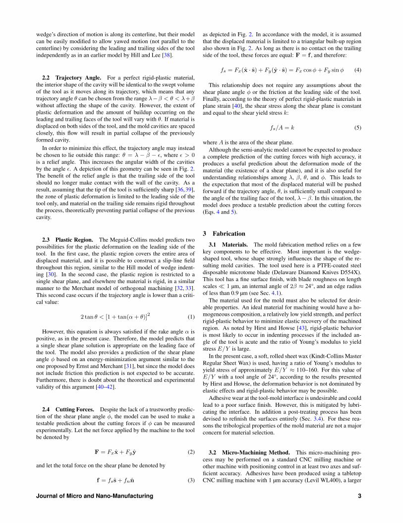
3.2.2 Lubrication. Without lubrication, adhesive wear occursbetween the tool and the mold material. SEM examination of themicro-wedges cast from these molds indicates significant surfaceroughness on critical areas such as the engaging faces that will ul-timately generate adhesion (see Fig. 3a). To address this issue, alubricant has been added to the process to inhibit material transferfrom the wax mold to the tool. Several fluids were tested, includingvarious mixtures of water and surfactants in the form of liquid dishsoaps. The resulting surfaces were characterized using SEM 3Dstereo microscopy, as described in Sec. 4.4. The lowest roughnesswas obtained with a 10:2 concentration of Ajax liquid dish soap(Colgate-Palmolive) to water. This improvement in surface finishcan be seen in Fig. 3b.
3.3 Casting. The completed mold is cleaned with solventsand water to remove all traces of lubricant. A PDMS silicone elas-tomer (Dow Corning Sylgard 170) is vacuum de-gassed and pouredinto the mold. For samples for adhesion force testing, a 300 µmthick backing layer of PDMS is desired. This can be achieved byspinning the mold at 160 RPM for 30 seconds, or alternatively atwo-part mold may be created by placing a flat sheet of glass upon300 µm supports which rest on the wax mold surface. For climbingapplications [7], the sheet of glass may be replaced by a rigid tilemade of glass fiber or aluminum. The tile is treated with a primer(Dow Corning PR-1200), which allows the PDMS to bond directlyto the tile. In any case, the casting is then allowed to cure at roomtemperature for 24 hours (heat acceleration is not suitable due tothermal expansion of the wax). Once removed from the mold, theelastomeric adhesive is ready for use. The mold may become dam-aged as the castings are de-molded, in which case the mold may beresurfaced and micromachined again before its next use (see dis-cussion in Sec. 5).
10μm 100μm
b.
a. c.
10μm
Fig. 3 Surface comparison of PDMS micro-wedges cast frommicro-machined wax molds, using (a) no lubricant, (b) liquidsoap lubricant, and (c) liquid soap lubricant and “inking” post-treatment. A broken wedge, illustrating the wedges’ taperedprofile, can be seen on the right.
3.4 Post-treatment. While the addition of lubrication to themicro-machining process improves the surface finish of the moldsand molded wedges, there is still remaining roughness that affectsthe performance of the adhesives by reducing the real area of con-tact between the adhesive and the substrate. In order to furtherreduce this roughness, a post-treatment is employed after casting.This treatment adds a thin, smooth secondary layer of PDMS to theengaging faces of the wedges. The treatment proceeds as follows(see Fig. 4):
1. Uncured PDMS is diluted to a concentration of 10% tolueneby volume. The diluted mixture is then poured onto a four-inchquartz wafer and spun at 8000 RPM for 60 seconds to obtain auniform thin layer 3–5 µm thick.
2. One half of the wafer is cleaned using isopropyl alcohol, andthe wafer and a cast adhesive sample are secured to a threeaxis motorized positioning stage (described in Sec. 4.5). Theadhesive sample is aligned using the positioning stage’s two-axis goniometer.
3. The sample is brought into contact with the PDMS-coated halfof the wafer. After applying a normal load so that the wedgesare in contact with the wafer over approximately one third oftheir length, the adhesive is taken out of contact, leaving a thin,wet layer of PDMS on the tips of the wedges.
4. After this “inking” procedure, the adhesive is loaded againstthe cleaned half of the wafer and held there in order to flattenthis thin, wet layer as it cures.
5. The cured thin layer binds strongly to the previously curedwedges. The post-treatment results in smooth patches ofPDMS on the engaging faces of the wedges (see Fig. 3c).
Although the thin layer of PDMS deposited on the tips of thewedges is smooth, the surface roughness of the wedges in the sub-jacent region near the bottom of the wedges appears to be adverselyaffected by post-treatment (this roughness is visible in Fig. 3c).However, this region does not contact the substrate unless the adhe-sive is subjected to extreme loads.
For a climbing adhesive which has been cast directly to a rigidtile, the post-treatment may be done without the motorized posi-tioning stage, by simply using an appropriately sized weight. In thisvariation of the process, the wafer is placed on a flat surface, the ad-hesive is placed on the wafer (with the back of the tile facing up),
4 Transactions of the ASME

QuartzWafer
100μm
CuredPDMS
UncuredPDMS
3-5μm
1.
2.
3.
4.
5.
Fig. 4 Diagram illustrating the steps of the post-treatment process (see text for details)
40μm
24° 34°
Secondarybevel
270μm
Tertiarybevel
1.7mm
Primarybevel
Fig. 5 Cross-section of microtome blade used in the micro-machining process, showing its three different beveled sections
and the weight is placed on the tile. This passive alignment tech-nique is more effective than using a rigid positioning stage for largeadhesive tiles, because it becomes increasingly difficult to activelyalign the surfaces as their size increases. Using weights instead of apositioning stage, angular alignment within 0.03° has been achieved(less than 20 µm of height misalignment over a 44 mm length ofadhesive). The best post-treatment results have been obtained usingweights such that the average pressure is approximately 7–8 kPa,but this depends on the shape and stiffness of the wedges.
4 ResultsExperiments were performed to test the semi-analytic model in-
troduced in Sec. 2, to empirically characterize the micro-machiningprocess, to characterize the surface roughness of the micro-machined micro-wedges, and to measure the adhesive performanceof macroscopic arrays of wedges. These experiments and their re-sults are presented in Secs. 4.2, 4.3, 4.4, and 4.5. However, it is firstnecessary to look more closely at the geometry of the microtomeblades used here as micro-machining tools.
4.1 Tool Geometry. As seen in Fig. 5, the blades are not sim-ply a triangular wedge. Instead, the manufacturer has sharpenedthem to a profile with three different beveled sections. The primarybevel begins approximately 1.7 mm from the tip and has an angle of12° (this section is above the wax mold at all times). The secondarybevel begins 270 µm from the tip and has an angle of 24°, and thetertiary bevel extends over the final 40 µm of the blade’s length andis 34° wide. The tip is too small to be seen at this magnification,
but an upper limit radius of 0.9 µm may be established.In the described machining geometry, the border between the sec-
ondary and tertiary bevels is below the surface of the wax wheneverthe blade is inserted more than 40 µm deep. However, the mold cav-ities created by the micro-machining process (with a nominal depthof 100 µm) show little evidence of this border, and the terminal an-gle of the PDMS wedges is considerably narrower than the tertiaryblade bevel. This implies that there is significant elastic behavioroccurring in the mold material, as the tips of the mold cavities arenarrowing by several degrees when the blade is retracted. This ef-fect is observed for single cavities as well as arrays of cavities.
4.2 Cutting Force Tests. To test the predictions of the semi-analytic model, the cutting forces during micro-machining weremeasured. A wax specimen of width 1 cm was attached to a six-axisforce/torque sensor (ATI Gamma SI-32-2.5) which was mounted ina CNC milling machine, and a variety of micro-machining trajecto-ries were used to create cavities in the wax. The trajectories werelinear and differed by trajectory angle, ranging from θ = 36° to60°, and maximum depth, ranging from t = 20 µm to 100 µm. Theblade centerline angle was λ = 60° in all cases, an angle found em-pirically to produce adhesive features with the desired directionalbehavior. In this experiment, the cavities were spaced far apart(0.5 mm tip-to-tip) so that the interaction between them was neg-ligible. The blade was wider than the wax specimen so that its cor-ners were not in contact.
The resulting force data were analyzed to find the cutting force Fcorresponding to the endpoint of each trajectory, the point in timewhen the tool was at its maximum cutting depth t for each cavity.
Journal of Micro and Nano-Manufacturing 5
k (vonMises)
k (Tresca)
T S C-12
-10
-8
-6
-4
-2
0
2
4
36 40 44 48 52 56 60
Shearstressatshe
arplane
ƒs/A
(MPa
)
Trajectoryangle (degrees)
PDMS
Mold
Trajectory
Built-upregion
θa. b.
Shearplane
�93μm
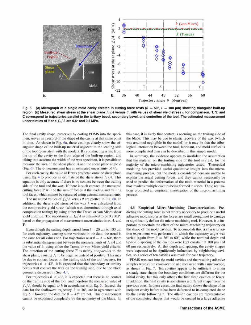
Fig. 6 (a) Micrograph of a single mold cavity created in cutting force tests (θ = 50°, t = 100 µm) showing triangular built-upregion. (b) Measured shear stress at the shear plane fs/A versus θ, with values of shear yield stress k for comparison. T, S, andC correspond to trajectories parallel to the tertiary bevel, secondary bevel, and centerline of the tool. The estimated measurementuncertainties of θ and fs/A are 0.6° and 0.8 MPa.
The final cavity shape, preserved by casting PDMS into the speci-men, serves as a record of the shape of the cavity at that same pointin time. As shown in Fig. 6a, these castings clearly show the tri-angular shape of the built-up material adjacent to the leading sideof the tool (consistent with the model). By constructing a line fromthe tip of the cavity to the front edge of the built-up region, andtaking into account the width of the wax specimen, it is possible tomeasure the area of the shear plane A and the shear plane angle φ(Fig. 6). The φ measurement has an estimated uncertainty of 4°.
For each cavity, the value of F was projected onto the shear planeusing Eq. 4 to produce an estimate of the shear stress fs/A. Thisequation is only accurate if there is no contact between the trailingside of the tool and the wax. If there is such contact, the measuredcutting force F will be the sum of forces at the leading and trailingtool faces, which cannot be separated using external measurements.
The measured values of fs/A versus θ are plotted in Fig. 6b. Inaddition, the shear yield stress of the wax k was calculated fromthe compressive yield stress (which was determined through axialcompression testing) by using either the Tresca or von Mises shearyield criterion. The uncertainty in fs/A is estimated to be 0.8 MPabased on the propagation of measurement uncertainties in φ,A, andF.
Even though the cutting depth varied from t = 20 µm to 100 µmfor each trajectory, causing some variance in the data, the trend isthe same for all values of t. For trajectories near θ = λ = 60°, thereis substantial disagreement between the measurements of fs/A andthe value of k, using either the Tresca or von Mises yield criteria.The direction of the cutting force F is nearly antiparallel to theshear plane, causing fs to be negative instead of positive. This maybe due to contact forces on the trailing side of the tool because, fortrajectories θ > 43°, it is expected that the secondary or tertiarybevels will contact the wax on the trailing side, due to the bladegeometry discussed in Sec. 4.1.
For trajectories θ < 43°, it is expected that there is no contacton the trailing side of the tool, and therefore the measured value offs/A should be equal to k in accordance with Eq. 5. Indeed, thedata for the shallowest trajectory, θ = 36°, are in agreement withEq. 5. However, the data for θ = 42° are not. This disagreementcannot be explained completely by the geometry of the blade. In
this case, it is likely that contact is occuring on the trailing side ofthe blade. This may be due to elastic recovery of the wax (whichwas assumed negligible in the model) or it may be that the tribo-logical interaction between the tool, lubricant, and mold surface ismore complicated than can be described in this simple model.
In summary, the evidence appears to invalidate the assumptionthat the material on the trailing side of the tool is rigid, for themajority of the micro-machining trajectories tested. Theoreticalmodeling has provided useful qualitative insight into the micro-machining process, but the models considered here are unable toexplain the actual cutting forces, and they cannot necessarily beused to predict the deformation of the mold material in a processthat involves multiple cavities being formed in series. These realiza-tions prompted an empirical investigation of the micro-machiningprocess.
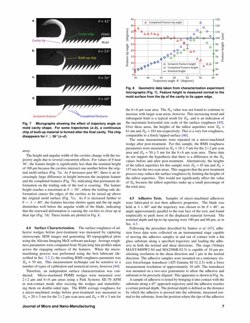
4.3 Empirical Micro-Machining Characterization. Pre-dicting the cutting force is not strictly necessary to produce a usefuladhesive mold insofar as the forces are small enough not to damageor significantly deflect the micro-machining tool. However, it is im-portant to ascertain the effect of the micro-machining trajectory onthe shape of the mold cavities. To accomplish this, a characteriza-tion experiment was performed in which the trajectory angle wasvaried (again from θ = 36° to 60°) while the nominal depth andtip-to-tip spacing of the cavities were kept constant at 100 µm and60 µm respectively. At this depth and spacing, the cavity shapeswere expected to be significantly influenced by neighboring cavi-ties, so a series of ten cavities was made for each trajectory.
PDMS was cast into the mold cavities and the resulting adhesivesamples were cut in cross-section and measured with a microscope,as shown in Fig. 7. Ten cavities appear to be sufficient to attaina steady-state shape; the boundary conditions are different for theinitial cavity, but this only affects the first three cavities or fewer.In addition, the final cavity is sometimes a different shape from theprevious ones. In these cases, the final cavity shows the shape of anincipient cavity before it has been deformed to its completed shapeby the cavity following it. The 4th–9th cavities are representativeof the completed shapes that would be created in a large adhesive
6 Transactions of the ASME
a.
Built-upchip
PDMS
Mold
Incipientfeature Completedfeatures
Cavityedge
Cavitytip
=42°θ
b. =53°θ
c. =56°θ
d. =60°θ
Fig. 7 Micrographs showing the effect of trajectory angle onmold cavity shape. For some trajectories (a–b), a continuouschip of built-up material is formed after the final cavity. The chipdisappears for θ ≥ 56° (c–d).
array.The height and angular width of the cavities change with the tra-
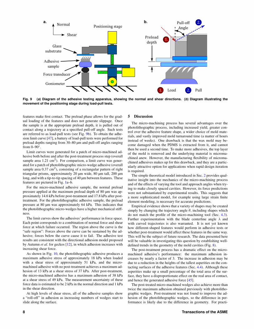
jectory angle due to several concurrent effects. For values of θ near36°, the feature height is significantly less than the nominal heightof 100 µm because the cavities intersect one another below the orig-inal mold surface (Fig. 7a). As θ increases past 46°, there is an in-creasingly large difference in height between the incipient featureand the completed features (Fig. 7b), indicating that permanent de-formation on the trailing side of the tool is ocurring. The featureheight reaches a maximum at θ = 56°, where the trailing-side de-formation causes the edges of the cavities to be raised up abovethe original mold surface (Fig. 7c). As θ is increased further toθ = λ = 60°, the features become shorter again and the tip anglediminishes well below the angular width of the blade, indicatingthat the rearward deformation is causing the cavities to close up attheir tips (Fig. 7d). These trends are plotted in Fig. 8.
4.4 Surface Characterization. The surface roughness of ad-hesive wedges before post-treatment was measured by capturingstereoscopic SEM images and generating 3D topographical plotsusing the Alicona Imaging MeX software package. Average rough-ness parameters were computed from 50 µm long line profiles takenacross the engaging surfaces of the features. When the micro-machining process was performed using the best lubricant (de-scribed in Sec. 3.2.2), the resulting RMS roughness parameter wasRq = 39 nm. This measurement technique can be sensitive to anumber of types of calibration and numerical errors, however [44].
Therefore, an independent surface characterization was con-ducted. Micro-machined PDMS wedges were measured over2×2 µm and 6×6 µm areas using a Park Systems XE-70 AFMin non-contact mode after excising the wedges and immobiliz-ing them on double-sided tape. The RMS average roughness fora micro-machined wedge before post-treatment was measured asRq = 20± 5 nm for the 2×2 µm scan area and Rq = 48± 5 nm for
40
50
60
70
80
90
100
110
120
130
0
5
10
15
20
25
30
35
40
45
36 40 44 48 52 56 60
Featur
ehe
ight
(μ
m)
Featur
etipan
gle(de
gree
s)
Trajectoryangle θ (degrees)
CompletedFeaturetipangle
Nominalheight
IncipientFeatureheightCompletedFeatureheight
Fig. 8 Geometric data taken from characterization experimentmicrographs (Fig. 7). Feature height is measured normal to themold surface from the tip of the cavity to its upper edge.
the 6×6 µm scan area. The Rq value was not found to continue toincrease with larger scan areas, however. This increasing trend andsubsequent limit is a typical result for Rq , and is an indication ofthe maximum horizontal size scale of the surface roughness [45].Over these areas, the heights of the tallest asperities were Rp =61 nm andRp = 183 nm respectively. This is a very low roughness,comparable to a finely lapped surface [46].
The same measurements were repeated on a micro-machinedwedge after post-treatment. For this sample, the RMS roughnessparameters were measured as Rq = 18± 5 nm for the 2×2 µm scanarea and Rq = 50± 5 nm for the 6×6 µm scan area. These datado not support the hypothesis that there is a difference in the Rq
values before and after post-treatment. Alternatively, the heightsof the tallest asperities for this sample were Rp = 45 nm and Rp =157 nm for the two scan areas. This suggests that the post-treatmentprocess may reduce the surface roughness by limiting the heights ofthe tallest asperities. This would not significantly affect the valueof Rq because the tallest asperities make up a small percentage ofthe total area.
4.5 Adhesive Tests. Samples of micro-machined adhesiveswere fabricated to test their adhesive properties. The blade washeld at λ = 60° and the trajectory was chosen to be θ = 48°, anangle approximately parallel to the rear face of the tool, and foundempirically to push most of the displaced material forward. Thenominal depth and tip-to-tip spacing were 100 µm and 60 µm, as inSec. 4.3.
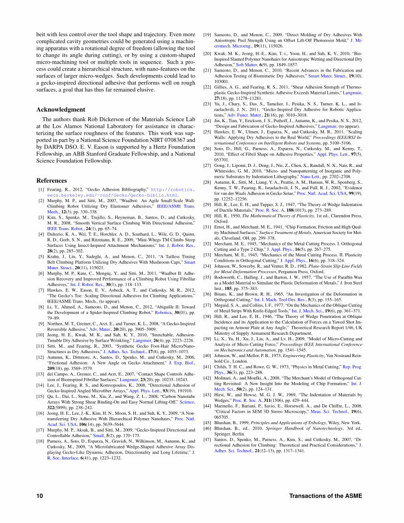
Following the procedure described by Santos et al. [47], adhe-sion force data were collected on an instrumented stage capableof moving the adhesive samples in and out of contact with a flatglass substrate along a specified trajectory and loading the adhe-sive in both the normal and shear directions. The stage (VelmexMAXY4009W2-S4 and MA2506B-S2.5) is capable of 10 µm po-sitioning resolution in the shear direction and 1 µm in the normaldirection. The adhesive samples were mounted on a stationary six-axis force/torque transducer (ATI Gamma SI-32-2.5) with a forcemeasurement resolution of approximately 10 mN. The transducerwas mounted on a two-axis goniometer to allow the adhesive andsubstrate to be precisely aligned. This apparatus is shown in Fig. 9a.
A sample of adhesive is tested by bringing it into contact with thesubstrate along a 45° approach trajectory until the adhesive reachesa certain preload depth. The preload depth is defined as the distanceby which the adhesive is pressed into the substrate, measured nor-mal to the substrate, from the position where the tips of the adhesive
Journal of Micro and Nano-Manufacturing 7
B
Goniometer
Force transducer
Adhesivesample
Glasssubstrate
Positioning stage
Shear
Normal
Preloaddepth
Pull-offAngle
1.
2.
1. 2.Load Pull
a. b.
Fig. 9 (a) Diagram of the adhesive testing apparatus, showing the normal and shear directions. (b) Diagram illustrating themovement of the positioning stage during load-pull tests.
features make first contact. The preload phase allows for the grad-ual loading of the features and does not generate slippage. Oncethe sample is at the appropriate preload depth, it is pulled out ofcontact along a trajectory at a specified pull-off angle. Such testsare referred to as load-pull tests (see Fig. 9b). To obtain the adhe-sion limit curve [47], a battery of load-pull tests were performed forpreload depths ranging from 30–80 µm and pull-off angles rangingfrom 0–90°.
Limit curves were generated for a patch of micro-machined ad-hesive both before and after the post-treatment process step (overallsample area 1.21 cm2). For comparison, a limit curve was gener-ated for a patch of photolithographic micro-wedge adhesive (overallsample area 0.37 cm2), consisting of a rectangular pattern of righttriangular prisms, approximately 20 µm wide, 80 µm tall, 200 µmlong, and with a tip-to-tip spacing of 40 µm between features. Thesefeatures are pictured in Fig. 1a–b.
For the micro-machined adhesive sample, the normal preloadpressure applied at the maximum preload depth of 80 µm was ap-proximately 14.6 kPa before post-treatment and 17.8 kPa after post-treatment. For the photolithographic adhesive sample, the preloadpressure at 80 µm was approximately 64 kPa. This indicates thatthe photolithographic micro-wedges have a higher mechanical stiff-ness.
The limit curves show the adhesives’ performance in force space.Each point corresponds to a combination of normal force and shearforce at which failure occurred. The region above the curve is the“safe region”: Forces above the curve can be sustained by the ad-hesive; forces below the curve cause it to fail. The adhesive testresults are consistent with the directional adhesion model proposedby Autumn et al. for geckos [12], in which adhesion increases withincreasing shear force.
As shown in Fig. 10, the photolithographic adhesive produces amaximum adhesive stress of approximately 18 kPa when loadedwith a shear stress of approximately 51 kPa, and the micro-machined adhesive with no post-treatment achieves a maximum ad-hesion of 13 kPa at a shear stress of 37 kPa. After post-treatment,the micro-machined adhesive has a maximum adhesion of 38 kPaat a shear stress of 49 kPa. The measurement uncertainty of theseforce data is estimated to be 2 kPa in the normal direction and 1 kPain the shear direction.
At high levels of shear stress, all of the adhesive samples showa “roll-off” in adhesion as increasing numbers of wedges start toslide along the surface.
5 DiscussionThe micro-machining process has several advantages over the
photolithographic process, including increased yield, greater con-trol over the adhesive feature shape, a wider choice of mold mate-rials, and vastly improved mold turnaround time (a matter of hoursinstead of weeks). One drawback is that the wax mold may be-come damaged when the PDMS is extracted from it, and cannotthen be used a second time. To make more adhesives, the top layerof the mold is removed and the underlying material is microma-chined anew. However, the manufacturing flexibility of microma-chined adhesives makes up for this drawback, and they are a partic-ularly attractive option for applications when rapid design iterationis required.
The simple theoretical model introduced in Sec. 2 provides qual-itative insight into the mechanics of the micro-machining processand of the effects of varying the tool and approach angles when try-ing to make closely spaced cavities. However, its force predictionswere not substantiated by experimental results. This suggests thata more sophisticated model, for example using large strain finiteelement modeling, is necessary for accurate predictions.
Empirical evidence shows that a variety of shapes may be createdsimply by changing the trajectory angle θ, including shapes whichdo not match the profile of the micro-machining tool (Sec. 4.3).Further experimentation with the blade centerline angle λ andwith curved trajectories is also warranted. It is not yet knownhow different-shaped features would perform in adhesive tests orwhether post-treatment would affect these features in the same way.This will be the subject of future research. The data presented herewill be valuable in investigating this question by establishing well-defined trends in the geometry of the mold cavities (Fig. 8).
The post-treatment process has a dramatic effect on the micro-machined adhesive’s performance: the maximum adhesion in-creases by nearly a factor of 3. The increase in adhesion may bedue to a reduction in the heights of the tallest asperities on the con-tacting surfaces of the adhesive features (Sec. 4.4). Although theseasperities make up a small percentage of the total area of the sur-face, they have a disproportionate effect on the real area of contact,and hence the generated adhesive force [45].
The post-treated micro-machined wedges also achieve more thantwice the maximum adhesion obtained previously with photolitho-graphic wedges. Post-treatment was not found to improve the ad-hesion of the photolithographic wedges, so the difference in per-formance is likely due to the difference in geometry. For practi-
8 Transactions of the ASME

0 10 20 30 40 50 60 70 80−40
−30
−20
−10
0
10
ShearStress(kPa)
NormalStress(kPa)
Micro-machinedadhesiveMicro-machinedadhesive(post−treated)Photolithographicadhesive
Safe Region
Safe Region
Fig. 10 Comparison of the limit curves for macroscopic arrays of adhesive micro-wedges produced with micro-machined moldsand photolithographic molds. The measurement uncertainty of the data is estimated to be 2 kPa in normal and 1 kPa in shear.
cal reasons, it is difficult to make the photolithographic wedges atthe same angle of inclination as the micro-machined wedges; in-stead, they have one vertical and one angled surface. Consequently,they are stiffer in the normal direction and produce a larger elasticforce that subtracts from the net adhesive force. This assertion issubstantiated by the higher preload pressures required for the pho-tolithographic wedges. In contrast, the micro-machining processaffords more freedom to vary the angle of inclination and taper, andthe chosen micromachining geometry produces features which aremore compliant.
As a further illustration of the effects of varying wedge shape andorientation, the data in Fig. 10 also show much greater adhesion forpost-treated micro-machined wedges at low levels of applied shear.As a consequence, the post-treated micro-machined adhesive cansupport a maximum loading angle of 80° away from the surface forlight loads. Whether post-treated or not, the micro-machined adhe-sives are controllable because they have the property of frictionaladhesion [12]: the adhesion increases as the shear load increases,and the adhesion goes to zero as the shear load is removed becausethe limit curve goes through the origin. This property makes it pos-sible for a climbing robot to detach its feet with very little effort,simply by removing the applied shear force. The result is smooth,efficient climbing.
6 Conclusion and Future WorkIn addition to climbing, potential applications for gecko-inspired
directional adhesives range from fumble-free football gloves tomanufacturing processes involving the handling of materials. How-ever, if these adhesives are to see widespread use outside of thelaboratory, a scalable and cost-effective production method must befound.
By following the process discussed in this paper, it is possibleto create relatively large patches of gecko-inspired directional ad-hesives using inexpensive equipment. The micro-wedge micro-machining process also permits greater freedom to control theshapes of the adhesive features than is possible with molds pro-duced by photolithography. In the present case, by creating wedgeswith two angled surfaces instead of one vertical and one angledsurface, and utilizing a simple post-treatment “inking” process, itis possible to obtain a much higher maximum loading angle at low
levels of shear loading. This could be useful for applications involv-ing lightweight robots such as micro air vehicles or for handlingdelicate materials.
The essential requirements of the process described in this pa-per are (1) a suitable mold material with near-rigid/plastic behaviorand (2) the ability to control the trajectory of the tool, thereby con-trolling the movement of displaced material, so that mold cavitiescan be spaced close together while simultaneously controlling thecavity shape. The addition of a post-treatment step to the micro-machining process produces more than double the maximum adhe-sion obtained with corresponding adhesives from photolithographicmolds on a flat glass substrate.
Before post-treatment, the micro-machined wedges have an RMSaverage surface roughness of Rq = 48± 5 nm. The post-treatmentappears not to affect Rq within the measurement uncertainty, butmay reduce the height of the tallest asperities Rp. Additional mea-surements are required to confirm these results.
The current approach uses inexpensive and readily available ma-terials, including a computer-controlled stage with at least two de-grees of freedom (e.g., a CNC milling machine), a microtome bladefor the cutting tool, blocks of wax for the molds, and dish soap forthe lubricant. Many improvements are clearly possible. The in-denting trajectory may be easily modified to create different shapedfeatures, with higher aspect ratios, narrower tips, or different an-gles. Preliminary experiments suggest that even with the presenttool and a suitable lubricant, it may be possible to cut directly intoa soft metal. The resulting mold would be much more durable andcould survive many molding cycles. Other possibilities include ma-chining a temperature-hardening material such as polymer clay, orusing an investment casting process to create a second-generationmold from a more durable material than wax.
The adhesives perform very well on glass, but do not perform aswell on rougher surfaces. To improve the adhesion on everyday sur-faces with micro-scale roughness, a siping step could be employedafter de-molding the adhesive. Specifically, the wedges could becut perpendicular to their longest dimension at a desired frequency,thereby allowing small, independent sections of the wedge to con-form to surface roughness.
Additionally, with suitably precise and stiff positioning equip-ment, much smaller terminal features should also be possible. Asnoted in Sec. 1, others have performed nanoscale machining, al-
Journal of Micro and Nano-Manufacturing 9
beit with less control over the tool shape and trajectory. Even morecomplicated cavity geometries could be generated using a machin-ing apparatus with a rotational degree of freedom (allowing the toolto change its angle during cutting), or by using a custom-shapedmicro-machining tool or multiple tools in sequence. Such a pro-cess could create a hierarchical structure, with nano-features on thesurfaces of larger micro-wedges. Such developments could lead toa gecko-inspired directional adhesive that performs well on roughsurfaces, a goal that has thus far remained elusive.
AcknowledgmentThe authors thank Rob Dickerson of the Materials Science Lab
at the Los Alamos National Laboratory for assistance in charac-terizing the surface roughness of the features. This work was sup-ported in part by a National Science Foundation NIRT 0708367 andby DARPA DSO. E. V. Eason is supported by a Hertz FoundationFellowship, an ABB Stanford Graduate Fellowship, and a NationalScience Foundation Fellowship.
References[1] Fearing, R., 2012, “Gecko Adhesion Bibliography,” http://robotics.
eecs.berkeley.edu/˜ronf/Gecko/gecko-biblio.html.[2] Murphy, M. P., and Sitti, M., 2007, “Waalbot: An Agile Small-Scale Wall-
Climbing Robot Utilizing Dry Elastomer Adhesives,” IEEE/ASME Trans.Mech., 12(3), pp. 330–338.
[3] Kim, S., Spenko, M., Trujillo, S., Heyneman, B., Santos, D., and Cutkosky,M. R., 2008, “Smooth Vertical Surface Climbing With Directional Adhesion,”IEEE Trans. Robot., 24(1), pp. 65–74.
[4] Daltorio, K. A., Wei, T. E., Horchler, A. D., Southard, L., Wile, G. D., Quinn,R. D., Gorb, S. N., and Ritzmann, R. E., 2009, “Mini-Whegs TM Climbs SteepSurfaces Using Insect-Inspired Attachment Mechanisms,” Int. J. Robot. Res.,28(2), pp. 285–302.
[5] Krahn, J., Liu, Y., Sadeghi, A., and Menon, C., 2011, “A Tailless TimingBelt Climbing Platform Utilizing Dry Adhesives With Mushroom Caps,” SmartMater. Struct., 20(11), 115021.
[6] Murphy, M. P., Kute, C., Menguc, Y., and Sitti, M., 2011, “Waalbot II: Adhe-sion Recovery and Improved Performance of a Climbing Robot Using FibrillarAdhesives,” Int. J. Robot. Res., 30(1), pp. 118–133.
[7] Hawkes, E. W., Eason, E. V., Asbeck, A. T., and Cutkosky, M. R., 2012,“The Gecko’s Toe: Scaling Directional Adhesives for Climbing Applications,”IEEE/ASME Trans. Mech., (to appear).
[8] Li, Y., Ahmed, A., Sameoto, D., and Menon, C., 2012, “Abigaille II: Towardthe Development of a Spider-Inspired Climbing Robot,” Robotica, 30(01), pp.79–89.
[9] Northen, M. T., Greiner, C., Arzt, E., and Turner, K. L., 2008, “A Gecko-InspiredReversible Adhesive,” Adv. Mater., 20(20), pp. 3905–3909.
[10] Jeong, H. E., Kwak, M. K., and Suh, K. Y., 2010, “Stretchable, Adhesion-Tunable Dry Adhesive by Surface Wrinkling,” Langmuir, 26(4), pp. 2223–2226.
[11] Sitti, M., and Fearing, R., 2003, “Synthetic Gecko Foot-Hair Micro/Nano-Structures as Dry Adhesives,” J. Adhes. Sci. Technol., 17(8), pp. 1055–1073.
[12] Autumn, K., Dittmore, A., Santos, D., Spenko, M., and Cutkosky, M., 2006,“Frictional Adhesion: A New Angle on Gecko Attachment,” J. Exp. Biol.,209(18), pp. 3569–3579.
[13] del Campo, A., Greiner, C., and Arzt, E., 2007, “Contact Shape Controls Adhe-sion of Bioinspired Fibrillar Surfaces,” Langmuir, 23(20), pp. 10235–10243.
[14] Lee, J., Fearing, R. S., and Komvopoulos, K., 2008, “Directional Adhesion ofGecko-Inspired Angled Microfiber Arrays,” Appl. Phys. Lett., 93(19), 191910.
[15] Qu, L., Dai, L., Stone, M., Xia, Z., and Wang, Z. L., 2008, “Carbon NanotubeArrays With Strong Shear Binding-On and Easy Normal Lifting-Off,” Science,322(5899), pp. 238–242.
[16] Jeong, H. E., Lee, J.-K., Kim, H. N., Moon, S. H., and Suh, K. Y., 2009, “A Non-transferring Dry Adhesive With Hierarchical Polymer Nanohairs,” Proc. Natl.Acad. Sci. USA, 106(14), pp. 5639–5644.
[17] Murphy, M. P., Aksak, B., and Sitti, M., 2009, “Gecko-Inspired Directional andControllable Adhesion,” Small, 5(2), pp. 170–175.
[18] Parness, A., Soto, D., Esparza, N., Gravish, N., Wilkinson, M., Autumn, K., andCutkosky, M., 2009, “A Microfabricated Wedge-Shaped Adhesive Array Dis-playing Gecko-Like Dynamic Adhesion, Directionality and Long Lifetime,” J.R. Soc. Interface, 6(41), pp. 1223–1232.
[19] Sameoto, D., and Menon, C., 2009, “Direct Molding of Dry Adhesives WithAnisotropic Peel Strength Using an Offset Lift-Off Photoresist Mold,” J. Mi-cromech. Microeng., 19(11), 115026.
[20] Kwak, M. K., Jeong, H.-E., Kim, T.-i., Yoon, H., and Suh, K. Y., 2010, “Bio-Inspired Slanted Polymer Nanohairs for Anisotropic Wetting and Directional DryAdhesion,” Soft Matter, 6(9), pp. 1849–1857.
[21] Sameoto, D., and Menon, C., 2010, “Recent Advances in the Fabrication andAdhesion Testing of Biomimetic Dry Adhesives,” Smart Mater. Struct., 19(10),103001.
[22] Gillies, A. G., and Fearing, R. S., 2011, “Shear Adhesion Strength of Thermo-plastic Gecko-Inspired Synthetic Adhesive Exceeds Material Limits,” Langmuir,27(18), pp. 11278–11281.
[23] Yu, J., Chary, S., Das, S., Tamelier, J., Pesika, N. S., Turner, K. L., and Is-raelachvili, J. N., 2011, “Gecko-Inspired Dry Adhesive for Robotic Applica-tions,” Adv. Funct. Mater., 21(16), pp. 3010–3018.
[24] Jin, K., Tian, Y., Erickson, J. S., Puthoff, J., Autumn, K., and Pesika, N. S., 2012,“Design and Fabrication of Gecko-Inspired Adhesives,” Langmuir, (to appear).
[25] Hawkes, E. W., Ulmen, J., Esparza, N., and Cutkosky, M. R., 2011, “ScalingWalls: Applying Dry Adhesives to the Real World,” Proceedings IEEE/RSJ In-ternational Conference on Intelligent Robots and Systems, pp. 5100–5106.
[26] Soto, D., Hill, G., Parness, A., Esparza, N., Cutkosky, M., and Kenny, T.,2010, “Effect of Fibril Shape on Adhesive Properties,” Appl. Phys. Lett., 97(5),053701.
[27] Gong, J., Lipomi, D. J., Deng, J., Nie, Z., Chen, X., Randall, N. X., Nair, R., andWhitesides, G. M., 2010, “Micro- and Nanopatterning of Inorganic and Poly-meric Substrates by Indentation Lithography,” Nano Lett., pp. 2702–2708.
[28] Autumn, K., Sitti, M., Liang, Y. A., Peattie, A. M., Hansen, W. R., Sponberg, S.,Kenny, T. W., Fearing, R., Israelachvili, J. N., and Full, R. J., 2002, “Evidencefor van der Waals Adhesion in Gecko Setae,” Proc. Natl. Acad. Sci. USA, 99(19),pp. 12252–12256.
[29] Hill, R., Lee, E. H., and Tupper, S. J., 1947, “The Theory of Wedge Indentationof Ductile Materials,” Proc. R. Soc. A, 188(1013), pp. 273–289.
[30] Hill, R., 1950, The Mathematical Theory of Plasticity, 1st ed., Clarendon Press,Oxford.
[31] Ernst, H., and Merchant, M. E., 1941, “Chip Formation, Friction and High Qual-ity Machined Surfaces,” Surface Treatment of Metals, American Society for Met-als, Cleveland, OH, pp. 299–378.
[32] Merchant, M. E., 1945, “Mechanics of the Metal Cutting Process. I. OrthogonalCutting and a Type 2 Chip,” J. Appl. Phys., 16(5), pp. 267–275.
[33] Merchant, M. E., 1945, “Mechanics of the Metal Cutting Process. II. PlasticityConditions in Orthogonal Cutting,” J. Appl. Phys., 16(6), pp. 318–324.
[34] Johnson, W., Sowerby, R., and Venter, R. D., 1982, Plane-Strain Slip-Line Fieldsfor Metal-Deformation Processes, Pergamon Press, Oxford.
[35] Bodsworth, C., Halling, J., and Barton, J. W., 1957, “The Use of Paraffin Waxas a Model Material to Simulate the Plastic Deformation of Metals,” J. Iron SteelInst., 185, pp. 375–383.
[36] Bitans, K., and Brown, R. H., 1965, “An Investigation of the Deformation inOrthogonal Cutting,” Int. J. Mach. Tool Des. Res., 5(3), pp. 155–165.
[37] Meguid, S. A., and Collins, I. F., 1977, “On the Mechanics of the Oblique Cuttingof Metal Strips With Knife-Edged Tools,” Int. J. Mech. Sci., 19(6), pp. 361–371.
[38] Hill, R., and Lee, E. H., 1946, “The Theory of Wedge Penetration at ObliqueIncidence and its Application to the Calculation of Forces on a Yawed Shot Im-pacting on Armour Plate at Any Angle,” Theoretical Research Report 1/46, UKMinistry of Supply Armament Research Department.
[39] Li, X., Yu, H., Xu, J., Liu, A., and Lv, H., 2009, “Model of Micro-Cutting andAnalysis of Micro Cutting Force,” Proceedings IEEE International Conferenceon Mechatronics and Automation, pp. 1541–1545.
[40] Johnson, W., and Mellor, P. B., 1973, Engineering Plasticity, Van Nostrand Rein-hold Co., London.
[41] Childs, T. H. C., and Rowe, G. W., 1973, “Physics in Metal Cutting,” Rep. Prog.Phys., 36(3), pp. 223–288.
[42] Molinari, A., and Moufki, A., 2008, “The Merchant’s Model of Orthogonal Cut-ting Revisited: A New Insight Into the Modeling of Chip Formation,” Int. J.Mech. Sci., 50(2), pp. 124–131.
[43] Hirst, W., and Howse, M. G. J. W., 1969, “The Indentation of Materials byWedges,” Proc. R. Soc. A, 311(1506), pp. 429–444.
[44] Marinello, F., Bariani, P., Savio, E., Horsewell, A., and De Chiffre, L., 2008,“Critical Factors in SEM 3D Stereo Microscopy,” Meas. Sci. Technol., 19(6),065705.
[45] Bhushan, B., 1999, Principles and Applications of Tribology, Wiley, New York.[46] Bhushan, B., ed., 2010, Springer Handbook of Nanotechnology, 3rd ed.,
Springer, Berlin.[47] Santos, D., Spenko, M., Parness, A., Kim, S., and Cutkosky, M., 2007, “Di-
rectional Adhesion for Climbing: Theoretical and Practical Considerations,” J.Adhes. Sci. Technol., 21(12–13), pp. 1317–1341.
10 Transactions of the ASME