Embed Size (px)
Citation preview
15th conference on Power System Engineering, Thermodynamics & Fluid Flow - ES 2016
June 09 - 10, 2016, Pilsen, Czech Republic
MICRO TURBINE GENERATORS FOR WASTE HEAT RECOVERY AND COMPRESSED AIR ENERGY STORAGE
WEISS Andreas P. , ZINN Gerd
The paper introduces a micro turbine generator construction kit and discusses possible applications of such small machines below 100 kWel. The reasons why a simple single stage axial impulse turbine is used as standard expander are explained as well as its efficiency disadvantages. Thus, as an alternative a radial-inflow cantilever turbine was designed and numerically and experimentally investigated in comparison to the axial impulse stage. The expected and predicted efficiency benefit of about 3 % points could be confirmed.
Keywords: turbine, waste heat recovery, compressed air energy storage
Introduction
In a big scale – several or hundreds of megawatts – waste heat recovery or compressed air energy storage are state-of-the-art yet. Consider for example gas turbine power plants where the exhaust heat of the gas turbine is converted into additional electric power by a steam power cycle downstream. Few big CAES-Systems (Compressed-Air-Energy-Storage) have been used for decades [1]. CAES is nowadays considered as an important future means to handle the fluctuating energy production of growing renewable energies [2].
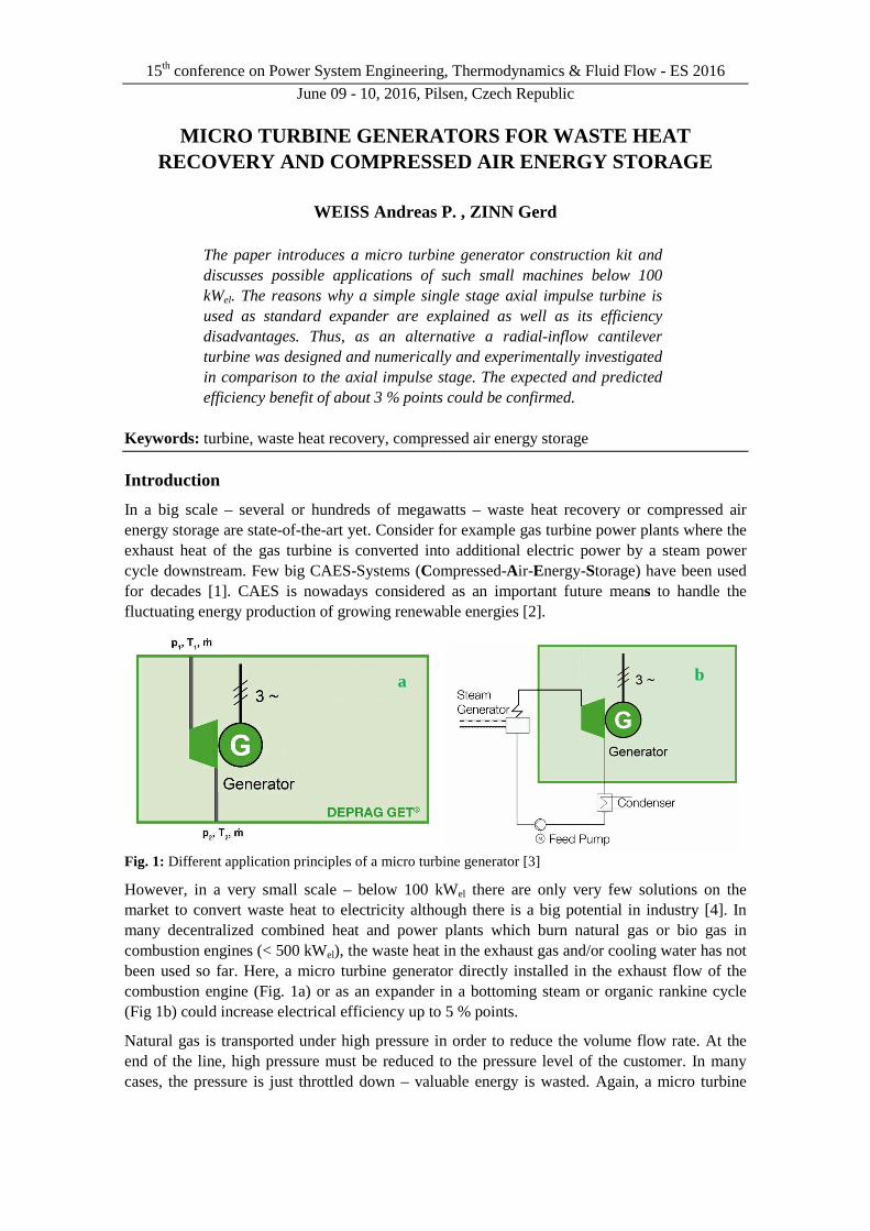
Fig. 1: Different application principles of a micro turbine generator [3]
However, in a very small scale – below 100 kWel there are only very few solutions on the market to convert waste heat to electricity although there is a big potential in industry [4]. In many decentralized combined heat and power plants which burn natural gas or bio gas in combustion engines (< 500 kWel), the waste heat in the exhaust gas and/or cooling water has not been used so far. Here, a micro turbine generator directly installed in the exhaust flow of the combustion engine (Fig. 1a) or as an expander in a bottoming steam or organic rankine cycle (Fig 1b) could increase electrical efficiency up to 5 % points.
Natural gas is transported under high pressure in order to reduce the volume flow rate. At the end of the line, high pressure must be reduced to the pressure level of the customer. In many cases, the pressure is just throttled down – valuable energy is wasted. Again, a micro turbine
a b
WEISS Andreas P., ZINN Gerd
generator could recover a portion of the energy which was necessary to bring the gas to the original high pressure level (Fig 1a).
In addition to that, there is another interesting application that should be mentioned. Most production plants use compressed air - e.g. to drive machines. The available compressed air system can be used as a compressed air (electrical) energy storage system if combined with a micro turbine generator. Occurring electrical load peaks could then be absorbed by the internal CAES-system, without having to buy expensive peak load electricity from the external provider.
Regarding all these possible applications, the authors are convinced that there is a growing market for micro turbine generators below 100 kWel. Thus, the company DEPRAG SCHULZ GMBH u. CO. and the University of Applied Sciences (UAS) Amberg-Weiden have been collaborating successfully for many years in developing those systems.
2. The micro-turbine-generator-construction-kit
Due to the various possible applications with different heat sources, heat flow rates, temperature levels, pressure levels and working fluids it is not appropriate to design and build some standard machines to stock. In fact, it is necessary to develop a very flexible micro-turbine-generator-construction-kit by means of which a customized turbine generator can be designed and built quickly for any required power output, any working fluid and any boundary conditions out of a wide range. In [5] the author discussed this task in more detail and came to the conclusion that a single stage axial impulse turbine mounted on a permanent magnet high-speed generator is the best i.e. most flexible compromise. Compared to a (radial-inflow) reaction turbine the axial single stage impulse turbine is able to process theoretically unlimited pressure ratios, requires lower rotational speed, does not produce axial thrust and can be designed with partial admission what allows the implementation of smaller turbines.
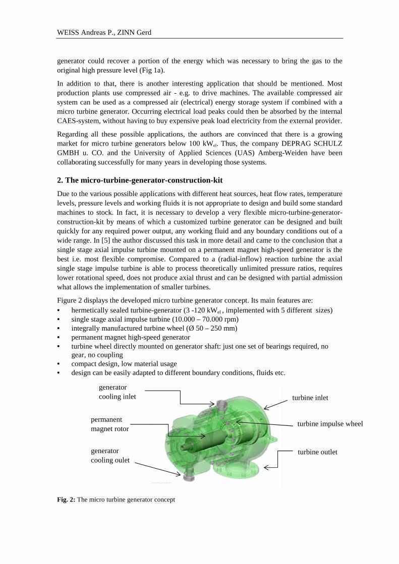
Figure 2 displays the developed micro turbine generator concept. Its main features are: • hermetically sealed turbine-generator (3 -120 kWel , implemented with 5 different sizes) • single stage axial impulse turbine (10.000 – 70.000 rpm) • integrally manufactured turbine wheel (Ø 50 – 250 mm) • permanent magnet high-speed generator • turbine wheel directly mounted on generator shaft: just one set of bearings required, no
gear, no coupling • compact design, low material usage • design can be easily adapted to different boundary conditions, fluids etc. Fig. 2: The micro turbine generator concept
turbine inlet
turbine outlet
turbine impulse wheel permanent magnet rotor
generator cooling inlet
generator cooling oulet
Micro Turbine Generators for Waste Heat Recovery and Compressed Air Energy Storage
3. The potential of the cantilever turbine concept
As mentioned in the chapter above the advantages of a pure impulse turbine design are the ability to process very high pressure ratios per stage and the option to design the turbine stage with partial admission due to the fact there is no pressure drop across the rotor blading (see Figure 3a).
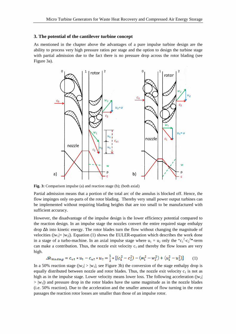
Fig. 3: Comparison impulse (a) and reaction stage (b); (both axial)
Partial admission means that a portion of the total arc of the annulus is blocked off. Hence, the flow impinges only on-parts of the rotor blading. Thereby very small power output turbines can be implemented without requiring blading heights that are too small to be manufactured with sufficient accuracy.
However, the disadvantage of the impulse design is the lower efficiency potential compared to the reaction design. In an impulse stage the nozzles convert the entire required stage enthalpy drop ∆h into kinetic energy. The rotor blades turn the flow without changing the magnitude of velocities (|w1|= |w2|). Equation (1) shows the EULER-equation which describes the work done in a stage of a turbo-machine. In an axial impulse stage where u1 = u2 only the “c1
2-c22”- term
can make a contribution. Thus, the nozzle exit velocity c1 and thereby the flow losses are very high.
(1)
In a 50% reaction stage (|w2| > |w1|; see Figure 3b) the conversion of the stage enthalpy drop is equally distributed between nozzle and rotor blades. Thus, the nozzle exit velocity c1 is not as high as in the impulse stage. Lower velocity means lower loss. The following acceleration (|w2| > |w1|) and pressure drop in the rotor blades have the same magnitude as in the nozzle blades (i.e. 50% reaction). Due to the acceleration and the smaller amount of flow turning in the rotor passages the reaction rotor losses are smaller than those of an impulse rotor.
WEISS Andreas P., ZINN Gerd
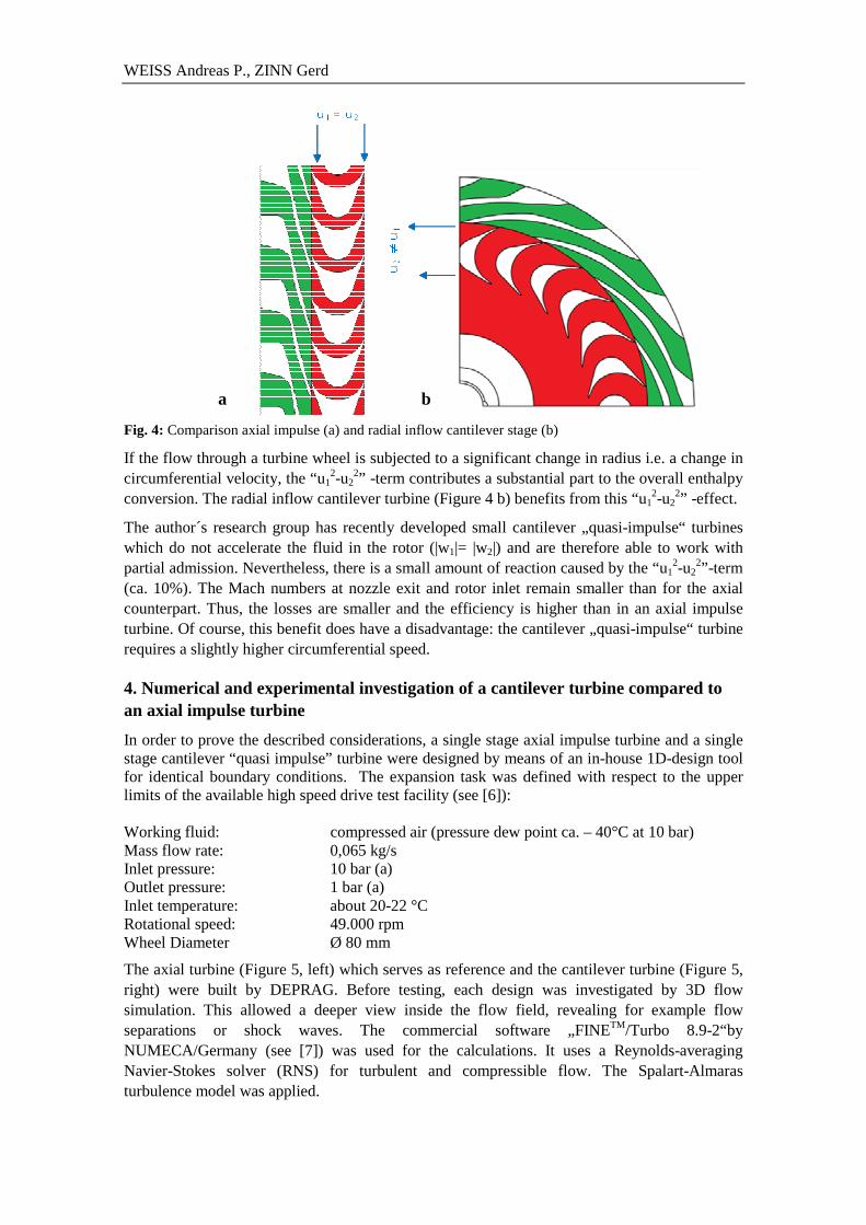
Fig. 4: Comparison axial impulse (a) and radial inflow cantilever stage (b)
If the flow through a turbine wheel is subjected to a significant change in radius i.e. a change in circumferential velocity, the “u1
2-u22” -term contributes a substantial part to the overall enthalpy
conversion. The radial inflow cantilever turbine (Figure 4 b) benefits from this “u12-u2
2” -effect.
The author´s research group has recently developed small cantilever „quasi-impulse“ turbines which do not accelerate the fluid in the rotor (|w1|= |w2|) and are therefore able to work with partial admission. Nevertheless, there is a small amount of reaction caused by the “u1
2-u22”-term
(ca. 10%). The Mach numbers at nozzle exit and rotor inlet remain smaller than for the axial counterpart. Thus, the losses are smaller and the efficiency is higher than in an axial impulse turbine. Of course, this benefit does have a disadvantage: the cantilever „quasi-impulse“ turbine requires a slightly higher circumferential speed.
4. Numerical and experimental investigation of a cantilever turbine compared to an axial impulse turbine
In order to prove the described considerations, a single stage axial impulse turbine and a single stage cantilever “quasi impulse” turbine were designed by means of an in-house 1D-design tool for identical boundary conditions. The expansion task was defined with respect to the upper limits of the available high speed drive test facility (see [6]): Working fluid: compressed air (pressure dew point ca. – 40°C at 10 bar) Mass flow rate: 0,065 kg/s Inlet pressure: 10 bar (a) Outlet pressure: 1 bar (a) Inlet temperature: about 20-22 °C Rotational speed: 49.000 rpm Wheel Diameter Ø 80 mm
The axial turbine (Figure 5, left) which serves as reference and the cantilever turbine (Figure 5, right) were built by DEPRAG. Before testing, each design was investigated by 3D flow simulation. This allowed a deeper view inside the flow field, revealing for example flow separations or shock waves. The commercial software „FINETM/Turbo 8.9-2“by NUMECA/Germany (see [7]) was used for the calculations. It uses a Reynolds-averaging Navier-Stokes solver (RNS) for turbulent and compressible flow. The Spalart-Almaras turbulence model was applied.
a b
Micro Turbine Generators for Waste Heat Recovery and Compressed Air Energy Storage
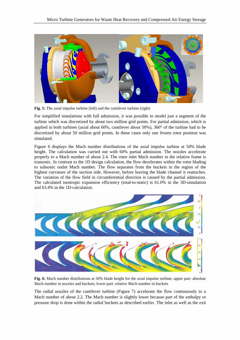
Fig. 5: The axial impulse turbine (left) and the cantilever turbine (right)
For simplified simulations with full admission, it was possible to model just a segment of the turbine which was discretized by about two million grid points. For partial admission, which is applied in both turbines (axial about 60%, cantilever about 50%), 360° of the turbine had to be discretized by about 50 million grid points. In these cases only one frozen rotor position was simulated.
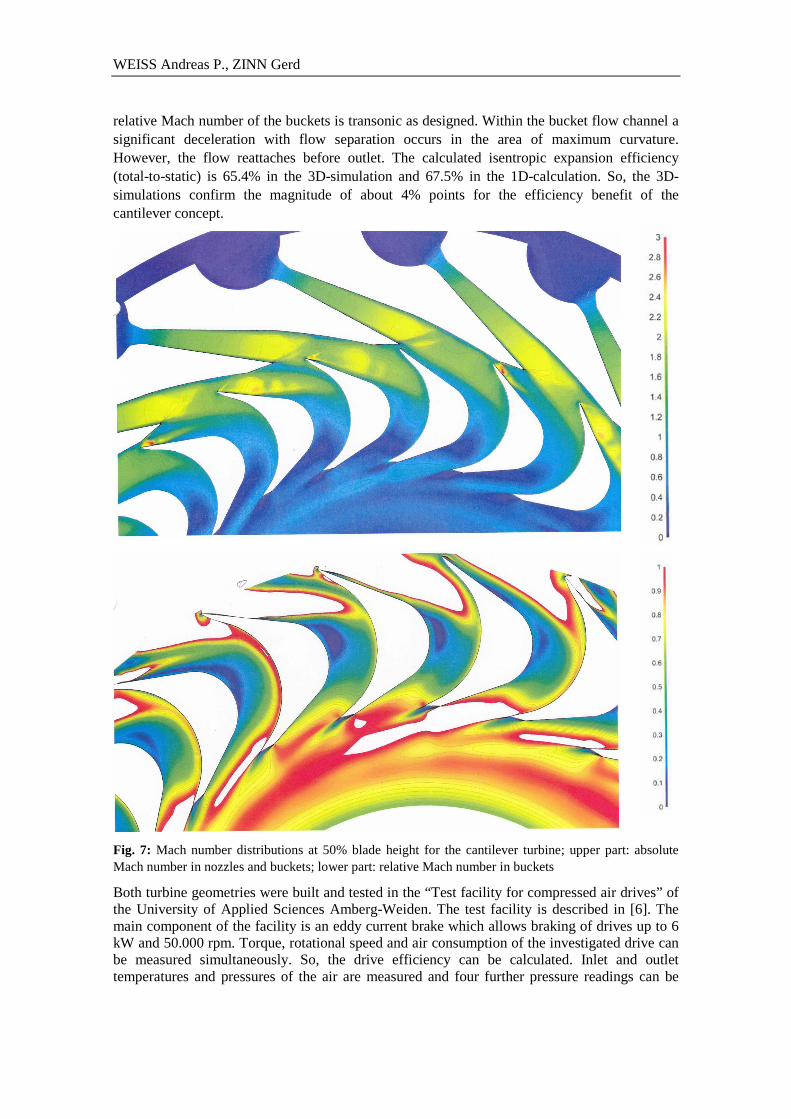
Figure 6 displays the Mach number distributions of the axial impulse turbine at 50% blade height. The calculation was carried out with 60% partial admission. The nozzles accelerate properly to a Mach number of about 2.4. The rotor inlet Mach number in the relative frame is transonic. In contrast to the 1D design calculation, the flow decelerates within the rotor blading to subsonic outlet Mach number. The flow separates from the buckets in the region of the highest curvature of the suction side. However, before leaving the blade channel it reattaches. The variation of the flow field in circumferential direction is caused by the partial admission. The calculated isentropic expansion efficiency (total-to-static) is 61.0% in the 3D-simulation and 63.4% in the 1D-calculation.
Fig. 6: Mach number distributions at 50% blade height for the axial impulse turbine; upper part: absolute Mach number in nozzles and buckets; lower part: relative Mach number in buckets
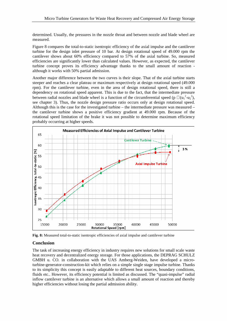
The radial nozzles of the cantilever turbine (Figure 7) accelerate the flow continuously to a Mach number of about 2.2. The Mach number is slightly lower because part of the enthalpy or pressure drop is done within the radial buckets as described earlier. The inlet as well as the exit
WEISS Andreas P., ZINN Gerd
relative Mach number of the buckets is transonic as designed. Within the bucket flow channel a significant deceleration with flow separation occurs in the area of maximum curvature. However, the flow reattaches before outlet. The calculated isentropic expansion efficiency (total-to-static) is 65.4% in the 3D-simulation and 67.5% in the 1D-calculation. So, the 3D-simulations confirm the magnitude of about 4% points for the efficiency benefit of the cantilever concept.
Fig. 7: Mach number distributions at 50% blade height for the cantilever turbine; upper part: absolute Mach number in nozzles and buckets; lower part: relative Mach number in buckets
Both turbine geometries were built and tested in the “Test facility for compressed air drives” of the University of Applied Sciences Amberg-Weiden. The test facility is described in [6]. The main component of the facility is an eddy current brake which allows braking of drives up to 6 kW and 50.000 rpm. Torque, rotational speed and air consumption of the investigated drive can be measured simultaneously. So, the drive efficiency can be calculated. Inlet and outlet temperatures and pressures of the air are measured and four further pressure readings can be
Micro Turbine Generators for Waste Heat Recovery and Compressed Air Energy Storage
determined. Usually, the pressures in the nozzle throat and between nozzle and blade wheel are measured.
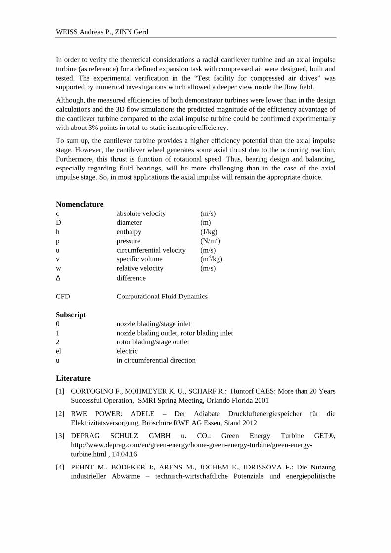
Figure 8 compares the total-to-static isentropic efficiency of the axial impulse and the cantilever turbine for the design inlet pressure of 10 bar. At design rotational speed of 49.000 rpm the cantilever shows about 60% efficiency compared to 57% of the axial turbine. So, measured efficiencies are significantly lower than calculated values. However, as expected, the cantilever turbine concept proves its efficiency advantage thanks to the small amount of reaction - although it works with 50% partial admission.
Another major difference between the two curves is their slope. That of the axial turbine starts steeper and reaches a clear plateau or maximum respectively at design rotational speed (49.000 rpm). For the cantilever turbine, even in the area of design rotational speed, there is still a dependency on rotational speed apparent. This is due to the fact, that the intermediate pressure between radial nozzles and blade wheel is a function of the circumferential speed (p ∼ (u1
2-u22),
see chapter 3). Thus, the nozzle design pressure ratio occurs only at design rotational speed. Although this is the case for the investigated turbine – the intermediate pressure was measured – the cantilever turbine shows a positive efficiency gradient at 49.000 rpm. Because of the rotational speed limitation of the brake it was not possible to determine maximum efficiency probably occurring at higher speeds.
Fig. 8: Measured total-to-static isentropic efficiencies of axial impulse and cantilever turbine
Conclusion
The task of increasing energy efficiency in industry requires new solutions for small scale waste heat recovery and decentralized energy storage. For those applications, the DEPRAG SCHULZ GMBH u. CO. in collaboration with the UAS Amberg-Weiden, have developed a micro-turbine-generator-construction-kit which relies on a simple single stage impulse turbine. Thanks to its simplicity this concept is easily adaptable to different heat sources, boundary conditions, fluids etc.. However, its efficiency potential is limited as discussed. The “quasi-impulse” radial inflow cantilever turbine is an alternative which allows a small amount of reaction and thereby higher efficiencies without losing the partial admission ability.
WEISS Andreas P., ZINN Gerd
In order to verify the theoretical considerations a radial cantilever turbine and an axial impulse turbine (as reference) for a defined expansion task with compressed air were designed, built and tested. The experimental verification in the “Test facility for compressed air drives” was supported by numerical investigations which allowed a deeper view inside the flow field.
Although, the measured efficiencies of both demonstrator turbines were lower than in the design calculations and the 3D flow simulations the predicted magnitude of the efficiency advantage of the cantilever turbine compared to the axial impulse turbine could be confirmed experimentally with about 3% points in total-to-static isentropic efficiency.
To sum up, the cantilever turbine provides a higher efficiency potential than the axial impulse stage. However, the cantilever wheel generates some axial thrust due to the occurring reaction. Furthermore, this thrust is function of rotational speed. Thus, bearing design and balancing, especially regarding fluid bearings, will be more challenging than in the case of the axial impulse stage. So, in most applications the axial impulse will remain the appropriate choice.
Nomenclature c absolute velocity (m/s) D diameter (m) h enthalpy (J/kg) p pressure (N/m2) u circumferential velocity (m/s) v specific volume (m3/kg) w relative velocity (m/s) ∆ difference CFD Computational Fluid Dynamics Subscript 0 nozzle blading/stage inlet 1 nozzle blading outlet, rotor blading inlet 2 rotor blading/stage outlet el electric u in circumferential direction
Literature
[1] CORTOGINO F., MOHMEYER K. U., SCHARF R.: Huntorf CAES: More than 20 Years Successful Operation, SMRI Spring Meeting, Orlando Florida 2001
[2] RWE POWER: ADELE – Der Adiabate Druckluftenergiespeicher für die Elektrizitätsversorgung, Broschüre RWE AG Essen, Stand 2012
[3] DEPRAG SCHULZ GMBH u. CO.: Green Energy Turbine GET®, http://www.deprag.com/en/green-energy/home-green-energy-turbine/green-energy-turbine.html , 14.04.16
[4] PEHNT M., BÖDEKER J:, ARENS M., JOCHEM E., IDRISSOVA F.: Die Nutzung industrieller Abwärme – technisch-wirtschaftliche Potenziale und energiepolitische
Micro Turbine Generators for Waste Heat Recovery and Compressed Air Energy Storage
Umsetzung, Institut für Energie- und Umweltforschung Heidelberg, Heidelberg, Karlsruhe 2013
[5] WEISS A. P.: Volumetric Expander Versus Turbine – Which is the better Choice for Small ORC Plants?, 3rd International Seminar on ORC Systems, October 12-14, Brussels, Belgium
[6] WEISS A. P.: Der Prüfstand für Druckluftantriebe und – technik, Interner Bericht, OTH Amberg-Weiden, 2012
[7] NUMECA Ingenieurbüro: FineTM/Turbo, http://www.numeca.de/index.php?article_id=37, 14.04.16
Acknowledgment
The project was funded by the “Technologie- und Wissenschaftsnetzwerk Oberpfalz” of the Bavarian Ministry of Education, Science and the Arts
Prof. Dr.-Ing. WEISS Andreas P., UAS Amberg-Weiden, Competence Center for CHP Systems, Kaiser-Wilhelm-Ring 23, 92224 Amberg, Germany, ++49 9621 482 3327, [email protected] Dipl.-Ing. (Univ.) ZINN Gerd, DEPRAG SCHULZ GMBH u. CO., Research & Development, Carl-Schulz-Platz 1, 92224 Amberg, Germany, ++49 9621 371 145, g.zinn@deprag .de