Embed Size (px)
Citation preview
MicroShield O/C Automation Technical Guide
1
MSOC AUTOMATION TECHNICAL GUIDE
TG 7.2.1.7-16
Version 1.6
02/02
MicroShield O/C Automation Technical Guide
i
CONTENTS
SECTION 1Introduction .....................................................................................................................2
SECTION 2MSOC Physical Layer Connectivity.........................................................................................3Physical Attachment of an RS 232 Device to the MSOC...........................................................3Physical Attachment of an RS 485 Device to the MSOC...........................................................4
SECTION 3MSOC Protocol Assignment .................................................................................................... 8Mapping Modbus Protocol to the RS 232 and RS 485 Ports ...................................................... 9Mapping MSOC Native ASCII Protocol................................................................................... 10Directing Communications Via the Front (RS232) or Rear (RS485) Ports ................................. 11
SECTION 4MSOC Protocol Description................................................................................................... 12Modbus Command Set ......................................................................................................... 12Modbus ASCII Protocol......................................................................................................... 120X Discrete Coils.................................................................................................................. 14Function Code 1 (Read Coil Status) – Read Only Data............................................................ 15Logical Outputs – 14 Discrete Coils (14 Elements Defined) ..................................................... 15Physical Outputs (4 Elements Defined) .................................................................................. 16Seal-In Outputs (14 Elements Defined) .................................................................................. 171X Discrete Contact Input...................................................................................................... 17Function Code 2 - Read Input Status (Read Only Data)........................................................... 17Logical Inputs (14 Elements Defined) .................................................................................... 18Physical Inputs (2 Elements Defined)..................................................................................... 184X Register Read Capabilities ............................................................................................... 19Function Code 03 – Read Holding Registers (Read Only)....................................................... 20Relay Status (1 Register Defined).......................................................................................... 21Diagnostic Status (2 Registers Defined)................................................................................. 22Unit Information (15 Registers Defined).................................................................................. 23Read Quick Status (3 Registers Defined) ............................................................................... 24Fast Status (1 Register Defined)............................................................................................ 24Logical Inputs (1 Register Defined) ........................................................................................ 24Physical Inputs (1 Register Defined) ...................................................................................... 25Logical Outputs (1 Register Defined)...................................................................................... 25Physical Outputs (1 Register Defined).................................................................................... 26Load Metering (27 Registers Defined) .................................................................................... 26Demand Metering (8 Registers Defined)................................................................................. 29Master Trip (5 Registers Defined) .......................................................................................... 304X Register Write Capabilities ............................................................................................... 31Function Code 16 Preset 4X Registers (Write Only)................................................................ 31Function 23 Read/Write Register (Read/Write Concurrently).................................................... 32Fault Records (27 Registers Defined)..................................................................................... 33Event Records (12 Registers Defined) ................................................................................... 36Mask Control Block (27 Registers Defined)............................................................................. 40Breaker Counters Modbus Function 03 (Read Only) ............................................................... 446X Registers .................................................................................................................... 45Function Code 20 (Read General Ref.) and 21 (Write General Ref.) ........................................ 45Relay Configuration Settings (20 Registers Defined) ............................................................... 47Primary Settings (39 Registers Defined)................................................................................. 47Aux Communication Settings (22 Registers Defined)............................................................... 51
MicroShield O/C Automation Technical Guide
ii
Real Time Clock (13 Registers Defined)................................................................................. 52Logical Input Map (19 Registers Defined) ............................................................................... 53Logical Outputs (19 Registers Defined).................................................................................. 54Master Trip (10 Registers Defined) ........................................................................................ 55Recloser Settings (69 Registers Defined)............................................................................... 56Breaker Counters (16 Registers Defined)............................................................................... 59Seal-In Mapping Table (20 Registers Defined)........................................................................ 59Calculation of the LRC (Longitudinal Redundancy Code)......................................................... 61MSOC Modbus Exception Response Analysis........................................................................ 61MSOC Modbus Communication Timing Analysis .................................................................... 62Modbus Baud Rate Analysis ................................................................................................. 63MSOC Throughput Analysis .................................................................................................. 64Final Throughput Calculation and Analysis............................................................................. 65MSOC ASCII Protocol........................................................................................................... 67MSOC Native ASCII “Menu Mode”......................................................................................... 67MSOC Native ASCII “Menu Mode” Terminal Configuration...................................................... 68MSOC Native ASCII “Menu Mode” Command Format ............................................................. 69MSOC Native ASCII “Fast ASCII Mode” ................................................................................. 76Fast ASCII Command Format................................................................................................ 77Fast ASCII Argument Definition ............................................................................................. 78Load Values (Read Only Commands).................................................................................... 79Demand Values (Read Only Commands)............................................................................... 81Event and Fault Records (Read Only).................................................................................... 82Logical I/O States ................................................................................................................. 86Logical Input State (Read Only)............................................................................................. 86Logical Output State (Read Only)........................................................................................... 88Seal-in Output State (Read Only)........................................................................................... 88Physical I/O States ............................................................................................................... 89Physical Input State (Read Only)........................................................................................... 89Physical Output State (Read Only)......................................................................................... 89Clock Commands (Read/Write) ............................................................................................. 89Miscellaneous Commands (Read Only).................................................................................. 91Miscellaneous Information..................................................................................................... 91Miscellaneous Commands .................................................................................................... 91Protective Settings (Read/Write)............................................................................................ 92Recloser Settings (Read/Write).............................................................................................. 94Configuration Settings (Read/Write)....................................................................................... 96Programmable Input/Output Settings ..................................................................................... 97Programmable Input Settings (Read/Write)............................................................................. 97Programmable Output Settings (Read/Write) .......................................................................... 97Programmable Seal-in Output Settings .................................................................................. 98Master Trip Output Settings ................................................................................................... 98Communications Settings & Information (Read/Write)............................................................. 99Breaker Counter Settings ...................................................................................................... 99MSOC Native ASCII Error Codes......................................................................................... 100MSOC Native ASCII “Fast Mode” Timing Analysis ................................................................ 100Fast ASCII Baud Rate Analysis ........................................................................................... 101MSOC Throughput Analysis ................................................................................................ 102Final Throughput Calculation and Analysis........................................................................... 103
SECTION 5Appendix A – ASCII Coding Chart ....................................................................................... 105Appendix B – RS 232 Device Connectivity ........................................................................... 107Appendix C – Connectivity of the MSOC with DPU/TPU/GPU 2000 (R).................................. 112Appendix D – MSOC Native ASCII Revision History.............................................................. 118Index ..................................................................................................................... 119
MicroShield O/C Automation Technical Guide
iii
TABLES
SECTION 3Table 3-1. MSOC Communication Port Default Settings ............................................................8Table 3-2. Valid Parameter Selections Per Protocol ..................................................................9
SECTION 4Table 4-1. Logical Output Modbus Address Map Definition...................................................... 16Table 4-2. Physical Output Modbus Address Map Definition .................................................... 16Table 4-3. Seal-In Output Modbus Address Map Definition...................................................... 17Table 4-4. Logical Input Modbus Address Map Definition......................................................... 18Table 4-5. Physical Input Modbus Address Map Definition....................................................... 18Table 4-6. Relay Status Modbus Address Map Definition......................................................... 21Table 4-7. Diagnostic Status Modbus Address Map Definition.................................................. 23Table 4-8. Unit Information Status Modbus Address Map Definition.......................................... 23Table 4-9. Quick Status Modbus Address Map Definition ........................................................ 24Table 4-10. Fast Status Modbus Address Map Definition......................................................... 24Table 4-11. Logical Input Modbus Address Map Definition....................................................... 25Table 4-12. Physical Input Modbus Address Map Definition..................................................... 25Table 4-13. Logical Output Modbus Address Map Definition .................................................... 26Table 4-14. Physical Output Modbus Address Map Definition .................................................. 26Table 4-15. Nominal Ratings for Current and Voltage.............................................................. 27Table 4-16. Load Metering Modbus Address Map Definition .................................................... 28Table 4-17. Demand Metering Modbus Address Map Definition ............................................... 30Table 4-18. Master Trip Modbus Address Map Definition......................................................... 31Table 4-19. Fault Status Modbus Address Map Definition........................................................ 34Table 4-20. Fault Codes ........................................................................................................ 35Table 4-21. Operation Record Address Definition.................................................................... 37Table 4-22. Event Record Type ............................................................................................. 38Table 4-23. Group 1 Control Function Bit Combinations .......................................................... 41Table 4-24. Configuration of Change Register State and Force Register State.......................... 41Table 4-25. Write Group Functionality .................................................................................... 41Table 4-26. Breaker Counter Definition Table ......................................................................... 45Table 4-27. Relay Configuration Setting Definition .................................................................. 47Table 4-28. Primary Settings Register Definition..................................................................... 50Table 4-29. Curve Selection Definition for 51LT (Register 60262) ............................................ 51Table 4-30. Curve Selection Definition for 51N and 51P (Registers 60274 and 60287) .............. 51Table 4-31. Curve Selection Definition for 50N and 50P (Registers 60274 and 60287) .............. 51Table 4-32. Communication Setting Register Definition........................................................... 52Table 4-33. Real Time Clock Register Definition Assignment ................................................... 53Table 4-34. Logical Input Mapping Definition .......................................................................... 54Table 4-35. Logical Input Codes for Mapping of Registers 61286-61299................................... 54Table 4-36. Logical Output Map Register Definition................................................................. 55Table 4-37. Logical Output Map Logical Mapping Definition for Registers 61542-61556 ............ 55Table 4-38. Master Trip Assignment Definition Table............................................................... 56Table 4-39. Recloser Assignment Definition Table.................................................................. 56Table 4-40. Breaker Counter Register Assignment.................................................................. 59Table 4-41. Seal In Output Definition Table ............................................................................ 59Table 4-42. Seal In Output Mapping Code Definition Table...................................................... 60Table 4-43. Modbus Standard Exception Codes ..................................................................... 62Table 4-44. MSOC Defined Exception Codes ......................................................................... 62Table 4-45. Character Transfer Time vs Baud Rate................................................................. 64Table 4-46. MSOC Modbus Command Throughtput (Average Time in mS) .............................. 65Table 4-47. Read and Read/Write Native MSOC ASCII Command Types ................................ 77Table 4-48. Load Value Command Listing .............................................................................. 80Table 4-49. Demand Value Access Command Codes ............................................................. 81
MicroShield O/C Automation Technical Guide
iv
Table 4-50. Event and Fault Record Access Codes ................................................................ 82Table 4-51. Event Codes (e- prefix based commands) ............................................................ 84Table 4-52. Fault Record Parameters and Formats (f based commands).................................. 85Table 4-53. MSOC Fault Codes ............................................................................................. 86Table 4-54. Event Record Value Formats............................................................................... 87Table 4-55. Event Record Parameter Formats........................................................................ 87Table 4-56. Logical Input Command Syntax ........................................................................... 87Table 4-57. Logical Output Command Syntax ......................................................................... 87Table 4-58. Latched Element Physical Output Syntax ............................................................. 88Table 4-59. Physical Input Command Formats ....................................................................... 89Table 4-60. Physical Input Command Formats ....................................................................... 89Table 4-61. Clock Command Syntax ...................................................................................... 90Table 4-62. Relay Status Commands ..................................................................................... 90Table 4-63. Status Bit Code Designations for xustat Command ............................................... 90Table 4-64. Miscellaneous Command Definition in Fast ASCII Mode........................................ 91Table 4-65. Protective Curve Abbreviations ............................................................................ 92Table 4-66. Protective Setting Fast ASCII Commands............................................................. 92Table 4-67. 51LT Curve Type Descriptions............................................................................. 92Table 4-68. 51N and 51P Curve Type Definition ..................................................................... 93Table 4-69. 50P and 50N Curve Selection Definitions ............................................................. 94Table 4-70. Recloser Command Codes.................................................................................. 94Table 4-71. Recloser Setting Command Codes ...................................................................... 95Table 4-72. Trip Setting Codes for Reclosure Function............................................................ 96Table 4-73. 51P Lockout Setting Codes for Reclosure Function............................................... 96Table 4-74. Configuration Command Settings......................................................................... 96Table 4-75. Programmable Input Setting Codes...................................................................... 97Table 4-76. Programmable Output Setting Codes ................................................................... 97Table 4-77. Programmable Seal-In Output Setting Codes........................................................ 98Table 4-78. Programmable Input, Output, and Seal-In nm Code Listing.................................... 98Table 4-79. Master Trip Output Setting Assignment Codes...................................................... 98Table 4-80. Communication Setting Parameter Assignment Codes .......................................... 99Table 4-81. Breaker Counter Setting Command List ............................................................... 99Table 4-82. Character Transfer Time vs Baud Rate............................................................... 101Table 4-83. MSOC Fast ASCII Command Throughput (Average Time in mS)......................... 102
The following are trademarks of AEG Schneider Automation Inc.Modbus, Modbus Plus, ModiconIBM, OS 2, and IBM PC are registered trademarks of International Business MachinesCorporation.The following are registered trademarks of the Microsoft Corporation:Windows NT Windows 3.1Windows 95 Windows 98Hyperterminal MS-DOSMicrosoft USDATA is a registered trademark of the USDATA Corporation.PRICOM and Power RICH are registered trademarks of Asea Brown Boveri Incorporated.LINUX , is a copyright of its respective entity.UNIX is a trademark of its respective entity.
MicroShield O/C Automation Technical Guide
v
FIGURESSECTION 2Figure 2-1. MSOC to PC Cable 9 to 9 Pin-Out ..........................................................................3Figure 2-2. RS 232 Point to Point Configuration........................................................................4Figure 2-3. Location of RS 485 Resistor Configuration Jumpers in the MSOC.............................5Figure 2-4. RS 485 Communication Device Connection ............................................................5Figure 2-5. ABB Physical Interface Converter to MSOC ............................................................7
SECTION 4Figure 4-1. Modbus Polling Sequence.................................................................................... 12Figure 4-2. Modbus ASCII Transmitted and Received Frame Formats ..................................... 13Figure 4-3. Modbus ASCII Frame Format ............................................................................... 13Figure 4-4. Modbus ASCII Frame Analysis............................................................................. 13Figure 4-5. Modbus Protocol Function 01 Frame Format ......................................................... 14Figure 4-6. Example Transaction Request for Four Coils......................................................... 15Figure 4-7. Example of Raw Data Decode.............................................................................. 15Figure 4-8. 1X Input Request Using Modbus Command 02...................................................... 17Figure 4-9. Read Input Breaker Status Example ..................................................................... 19Figure 4-10. Decode of Raw Data Bits Seen on Data Scope Analyzer...................................... 19Figure 4-11. 4X Data Read Frame Format.............................................................................. 20Figure 4-12. Application Example : Fetch Relay Status From MSOC........................................ 22Figure 4-13. Application Example : Returned Relay Response................................................. 22Figure 4-14. Current Demand Calculation............................................................................... 29Figure 4-15. Energy Demand Calculaion ................................................................................ 30Figure 4-16. Modbus Write Command 16 (10 HEX) Allowing Writes to MSOC.......................... 31Figure 4-17. Function 23 Read/Write Command Format ......................................................... 33Figure 4-18. Event and Operation Memory Map for the MSOC ................................................ 35Figure 4-19. Event Record Access Illustration if Function 23 is Issued to MSOC Device............ 35Figure 4-20. Update and Refresh Functionality ....................................................................... 40Figure 4-21. Scada Trip Sequence Example........................................................................... 43Figure 4-22. Pulse Physical Output Sequence Example.......................................................... 44Figure 4-23. Enable Reclose Trip Example............................................................................. 44Figure 4-24. Function 20 Read 6X Register Frame Definition................................................... 46Figure 4-25. Modbus Command 21- Write General Reference Format ..................................... 46Figure 4-26. Exception Code Example for Holding Register Read............................................ 62Figure 4-27. Example Communication Timing Topology .......................................................... 63Figure 4-28. Network Throughput Analysis at 1200 Baud ........................................................ 66Figure 4-29. Network Throughput Analysis at 19200 Baud....................................................... 66Figure 4-30. Main Menu Selection Screen .............................................................................. 69Figure 4-31. Meter Menu Submenu Selections ....................................................................... 69Figure 4-32. Show Settings Menu Selections.......................................................................... 70Figure 4-33. Show Settings Menu Selections (Continued) ....................................................... 70Figure 4-34. Example Change Setting Responses for Submenu [P]rotective Settings ............... 71Figure 4-35. Example Change Setting Responses for Submenu [C]onfiguration Settings........... 72Figure 4-36. Example Change Setting Responses for Submenu Programmable [I]nputs ........... 72Figure 4-37. Example Change Setting Responses for Submenu Programmable [O]utputs......... 73Figure 4-38. Change Setting Screen Example Illustrating the [M]aster Trip
and Commu[N]ication Settings Submenus ...................................................... 73Figure 4-39. Change Setting Screen for Real [T]ime Clock, [R]ecloser Settings
and Counter [S]ettings Submenus .................................................................. 74Figure 4-40. Record Menu Screen and Submenu Illustration ................................................... 74Figure 4-41. Operations Menu Selection with Submenu Illustrations......................................... 75Figure 4-42. Test Menu Selection Example with Submenu Illustrations .................................... 75Figure 4-43. Unit Information Example Screen........................................................................ 76Figure 4-44. Fast ASCII Command in HEX Format ................................................................. 78Figure 4-45. Read Load Current Phase A Example in HEX Format .......................................... 79

MicroShield O/C Automation Technical Guide
vi
Figure 4-46. Read 3 Phase K Vars Example........................................................................... 81Figure 4-47. Network Throughput Analysis at 1200 Baud ...................................................... 104Figure 4-48. Network Throughput Analysis at 19200 Baud..................................................... 104
MicroShield O/C Automation Technical Guide
2
Section 1 - Introduction
With the introduction of a microprocessor based protective relay, today’s relay protection engineer must be familiarwith topics outside of traditional relaying schemes. It is intended that the production of this guide will enable therelay engineer to understand the principles of a microprocessor-based relay’s inclusion in a substation automationproject.
Substation automation is heavily dependent upon integration of the appropriate components to allow reporting ofmetering and event data. The foundation of a successful automation solution is thorough engineering of acommunication system. The MicroShield Overcurrent Relay (MSOC) is the culmination of intensive design efforts,which combine protective relaying and communication capabilities at an economical price. Through the evolutionof protective relays, it was decided that a special guide was needed to serve today’s power automation specialist.
This guide is intended to give the reader an in-depth explanation of the communication interfaces available withthe MicroShield Overcurrent Relay. Successful integration of microprocessor based relays like the MSOC dependson not just understanding the bits and bytes of a particular protocol. It is the inherent understanding andapplication of such esoteric topics as physical interfaces, real time control, manufacturer independent deviceintegration, throughput vs. speed of communication, … which influences the success of an automation project.
In many cases the individual performing the SCADA integration is not a relay protection engineer. This guidedeparts from the standard type of relay manual in that each data type is explained and each bit and word isexplained. Several application examples are given within each section. A description of each protocol command isillustrated for the benefit of the user. Appendices are included detailing application notes, which augment the text.An explanation of the product’s physical interfaces and the connectivity required is explored in depth. Explanationsof register’s uses to increase overall throughput are also explored. Throughput is always an issue when the systemis commissioned. Understanding ways to improve the system data update is explained.
Three steps are required to permit successful communication between devices:
1. Correct physical cable connection between devices (Section 2).
2. Correct configuration of port protocol and device parameters (Section 3).
3. Generation and interpretation of the protocol command strings (Section 4).
The following sections shall explore the following procedures in depth when establishing a communicationautomation system, utilizing the MSOC.
Throughout this guide, implementation tips are included to aid the user in quick setup of the unit and advice to aidin troubleshooting if a problem is encountered. Implementation tips are denoted by the symbol ÿ preceeding theImplementation Tip Text. This makes the tip easier to find in the guide’s text.
MicroShield O/C Automation Technical Guide
3
Section 2 - MSOC Physical Layer Connectivity
The MSOC allows connectivity to a variety of devices through one of two physical interfaces. The physicalinterfaces available are RS 232 and RS 485. Only one of the two available interfaces may be enabled at one time.RS 232 allows direct point to point connectivity to a host device. RS 485 allows connectivity to a single or multipledevices. A DB 9 connector is available at the front of the unit. The DB 9 connector is the MSOC’s RS 232 physicalinterface. Depending upon the protocol selected for the RS 232 port; it may be a port to which an address isassigned. One protocol, Modbus allows for assignment of an address if the protocol is mapped to the front RS 232or rear RS 485 port. MSOC Native ASCII protocol does not allow for assignment of an address if the protocol isenabled for front port RS 232 operation. The MSOC Native ASCII protocol requires address vectoring if assignedto the rear RS 485 interface.
The RS 485 physical interface allows for attachment of multiple devices on a single communication cable. The RS485 interface allows for connection of up to 31 MicroShield Overcurrent Relays on a single cable. Connection tothe RS 485 interface is available the through three of the screw terminals located at the rear of the unit. If Modbusor Native MSOC ASCII protocol is selected, each command received through the port must have a device addressimbedded within the communication request.
The MSOC has two protocols within the unit, Modbus ASCII and MSOC Native ASCII protocol. In both cases, theMSOC acts as a slave device in that it waits for a command to be received from a host device and transmits aresponse to the command. Each device on a multi-dropped network has a unique address. This is required so thata command may be interpreted by a single device when transmitted. If two devices have the same address, acommunications collision will occur when both devices try to respond to the received command.
Physical Attachment of an RS 232 Device to the MSOC
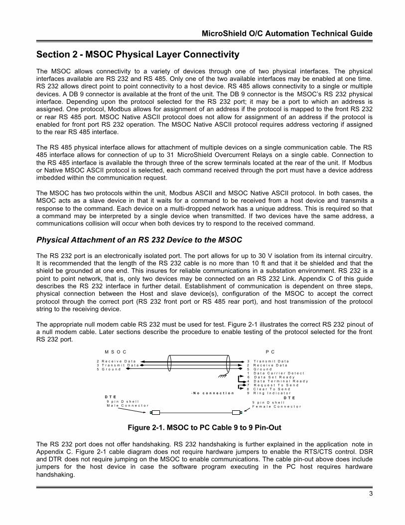
The RS 232 port is an electronically isolated port. The port allows for up to 30 V isolation from its internal circuitry.It is recommended that the length of the RS 232 cable is no more than 10 ft and that it be shielded and that theshield be grounded at one end. This insures for reliable communications in a substation environment. RS 232 is apoint to point network, that is, only two devices may be connected on an RS 232 Link. Appendix C of this guidedescribes the RS 232 interface in further detail. Establishment of communication is dependent on three steps,physical connection between the Host and slave device(s), configuration of the MSOC to accept the correctprotocol through the correct port (RS 232 front port or RS 485 rear port), and host transmission of the protocolstring to the receiving device.
The appropriate null modem cable RS 232 must be used for test. Figure 2-1 illustrates the correct RS 232 pinout ofa null modem cable. Later sections describe the procedure to enable testing of the protocol selected for the frontRS 232 port.
M S O C P C
2 R e c e i v e D a t a 3 T r a n s m i t D a t a3 T r a n s m i t D a t a 2 R e c e i v e D a t a5 G r o u n d 5 G r o u n d
1 D a t a C a r r i e r D e t e c t 6 D a t a S e t R e a d y
4 D a t a T e r m i n a l R e a d y 7 R e q u e s t T o S e n d 8 C l e a r T o S e n d
- N o c o n n e c t i o n 9 R i n g I n d i c a t o r
9 p i n D s h e l lM a l e C o n n e c t o r
9 p i n D s h e l lF e m a l e C o n n e c t o r
D T E D T E
Figure 2-1. MSOC to PC Cable 9 to 9 Pin-Out
The RS 232 port does not offer handshaking. RS 232 handshaking is further explained in the application note inAppendix C. Figure 2-1 cable diagram does not require hardware jumpers to enable the RTS/CTS control. DSRand DTR does not require jumping on the MSOC to enable communications. The cable pin-out above does includejumpers for the host device in case the software program executing in the PC host requires hardwarehandshaking.
MicroShield O/C Automation Technical Guide
4
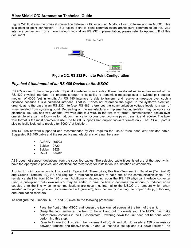
Figure 2-2 illustrates the physical connection between a PC executing Modbus Host Software and an MSOC. Thisis a point to point connection. It is a typical point to point communication architecture common to an RS 232interface connection. For a more in-depth look at an RS 232 implementation, please refer to Appendix B of thisdocument.
S C A D A M a s t e r
P r o t e c t i v e R e l a y
P o i n t t o P o i n t
S lave Dev i ce
A d d r e s s X
E
C
N e t w o r kPartnerV 1 . 0
Figure 2-2. RS 232 Point to Point Configuration
Physical Attachment of an RS 485 Device to the MSOC
RS 485 is one of the more popular physical interfaces in use today. It was developed as an enhancement of theRS 422 physical interface. Its inherent strength is its ability to transmit a message over a twisted pair coppermedium of 4000 feet in length. An RS 485 interface is able to transmit and receive a message over such adistance because it is a balanced interface. That is, it does not reference the signal to the system’s electricalground, as is the case in an RS 232 interface. RS 485 references the communication voltage levels to a pair ofwires isolated from system ground. Depending on the manufacturer’s implementation, isolation may be optical orelectronic. RS 485 has two variants, two-wire and four-wire. In the two-wire format, communication occurs overone single wire pair. In four-wire format, communication occurs over two-wire pairs, transmit and receive. The two-wire format is the most common in use. The MSOC supports half duplex two-wire format only. The RS 485 port isalso optically isolated to provide for 3000 V of isolation.
The RS 485 network supported and recommended by ABB requires the use of three conductor shielded cable.Suggested RS 485 cable and the respective manufacturer’s wire numbers are:
• ALPHA 58902• Belden 9729• Belden 9829• Carol 58902
ABB does not support deviations from the specified cables. The selected cable types listed are of the type, whichhave the appropriate physical and electrical characteristics for installation in substation environments.
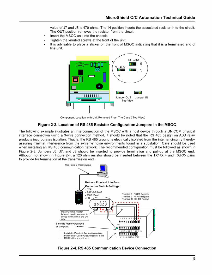
A point to point connection is illustrated in Figure 2-4. Three wires, Positive (Terminal 9), Negative (Terminal 8)and Ground (Terminal 10). RS 485 requires a termination resistor at each end of the communication cable. Theresistance shall be from 90 to 120 ohms. Additionally, depending upon the RS 485 physical interface converterused, a pull-up and pull-down resistor may be added to bias the line to decrease the amount of induced noisecoupled onto the line when no communications are occurring. Internal to the MSOC are jumpers which wheninserted in the proper position (as referenced in Figure 2-3), bias the line by inserting the proper pull-up, pull-down,and termination resistors.
To configure the Jumpers J6, J7, and J8, execute the following procedure:
• Face the front of the MSOC and loosen the two knurled screws at the front of the unit.• Grasp the two handles at the front of the unit and pull it towards you. The MSOC has make
before break contacts in the CT connectors. Powering down the unit need not be done whenperforming this step.
• Refer to Figure 2-3 illustrating the placement of J6, J7 and J8. J6 inserts a 120 ohm resistorbetween transmit and receive lines. J7 and J8 inserts a pull-up and pull-down resistor. The
MicroShield O/C Automation Technical Guide
5
value of J7 and J8 is 470 ohms. The IN position inserts the associated resistor in to the circuit.The OUT position removes the resistor from the circuit.
• Insert the MSOC unit into the chassis.• Tighten the knurled screws at the front of the unit.• It is advisable to place a sticker on the front of MSOC indicating that it is a terminated end of
line unit.
Jumper OUT Jumper IN Top View
J8
J7
J6
OUT IN
OUT IN
Component Location with Unit Removed From The Case ( Top View)
Figure 2-3. Location of RS 485 Resistor Configuration Jumpers in the MSOC
The following example illustrates an interconnection of the MSOC with a host device through a UNICOM physicalinterface connection using a 3-wire connection method. It should be noted that the RS 485 design on ABB relayproducts incorporates isolation. That is, the RS 485 ground is electrically isolated from the internal circuitry therebyassuring minimal interference from the extreme noise environments found in a substation. Care should be usedwhen installing an RS 485 communication network. The recommended configuration must be followed as shown inFigure 2-3. Jumpers J6, J7, and J8 should be inserted to provide termination and pull-up at the MSOC end.Although not shown in Figure 2-4, a 120 ohm resistor should be inserted between the TX/RX + and TX/RX- pairsto provide for termination at the transmission end.
Unicom Physical Interface Converter Switch Settings:- DTE- RS232-RS485- 9600 Baud- HD
Use Figure 2-1 Cable Above
TX
-R
X -
TX +
RX
+G
ND
Shield is Frame Grounded at one point
1 2 3 4 5 6 7 8 9 10
11 12 13 14 15 16 17 18 19 20
21 22 23 24 25 26 27 28
GND
Terminal 8 - RS485 CommonTerminal 9 - RS 485 NegativeTerminal 10- RS 485 Positive
Install J6, J7 and J8- Termination resistor,Pullup resistor, and Pulldown resistor in the MSOC at the end unit only.
Install 120 ohm resistorbetween + and - terminals fordevice termination at end unitonly.
Figure 2-4. RS 485 Communication Device Connection
MicroShield O/C Automation Technical Guide
6
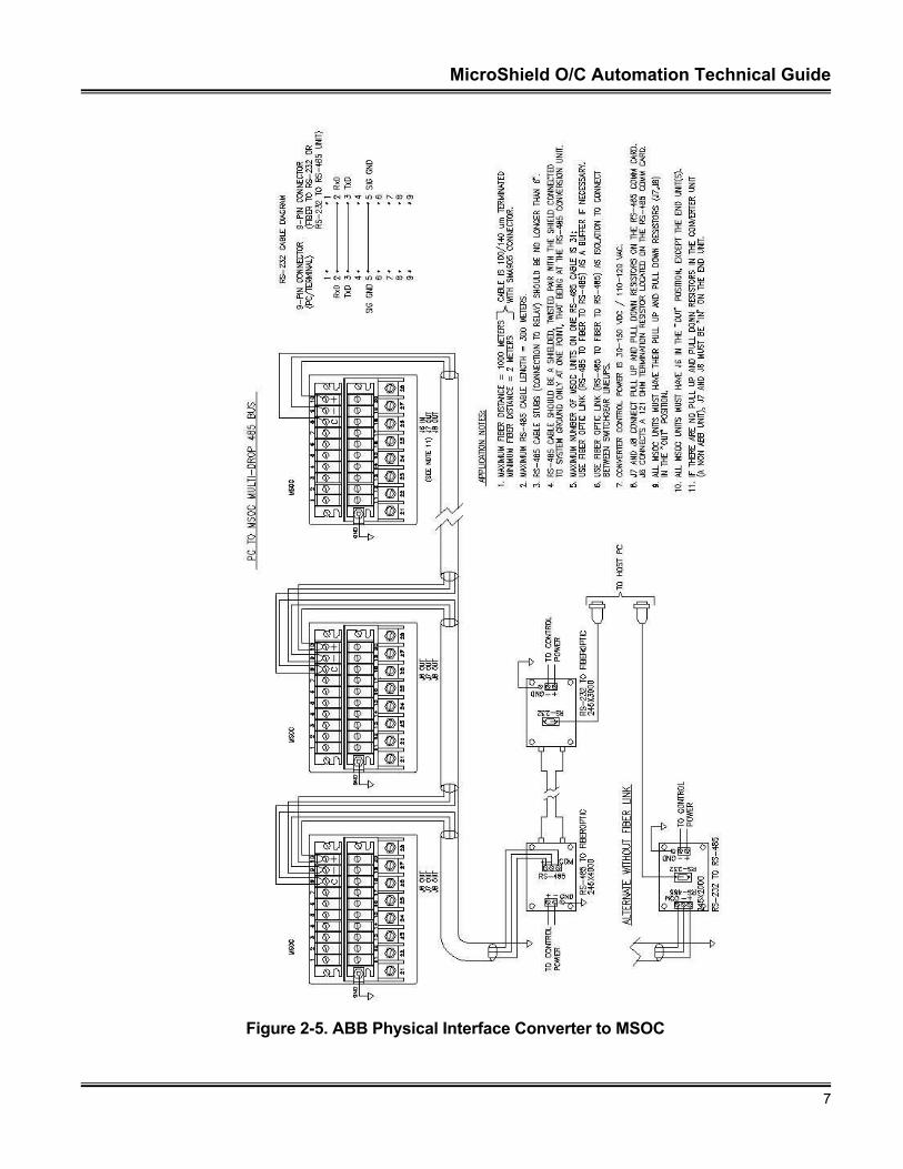
Figure 2-5 illustrates the connection of multiple devices on an RS 485 network using an ABB RS 232 to RS 485physical interface converter. It should be stressed that the ABB converter works only at baud rates less than 9600.Additionally, the ABB converter does not offer handshaking and is a DCE RS 232 configuration node. A straightthrough cable can be used if the host does not require handshaking. It should be pointed out that the RS 485portion of the diagram illustrates the three-wire connection of Positive, Negative and Ground. The shield is isolatedat each point and tied to ground at one end only.
The physical configurations contained within the section for RS 485 must be followed implicitly. The diagrams areprotocol independent. The ABB implementation of RS 485 uses an optically isolated port, which allows 3000 Visolation. Some vendors protocol converters will not work with isolated ports. For a more complete example ofinterconnecting multiple devices on an RS 485 network, please refer to the application note contained in AppendixC of this guide.
ÿ IMPLEMENTATION TIP–Some manufacturer’s RS 485 physical interface converters require that aphysical switch or hardware jumper be inserted to allow the device to operate correctly with devices suchas the MSOC which do not incorporate hardware port handshaking. The jumper allows RS 485 receivertransmitter control via sensing of the transmit data pin of the RS 232 interface. Consult the physicalinterface vendor’s documentation for additional information.
MicroShield O/C Automation Technical Guide
7
Figure 2-5. ABB Physical Interface Converter to MSOC
MicroShield O/C Automation Technical Guide
8
Section 3 - MSOC Protocol Assignment
The MSOC has a front panel interface, which allows the operator to assign a protocol and port parameters. TheUP Arrow, DOWN Arrow, LEFT Arrow, RIGHT Arrow, <C> (Change) and <E> (Enter) keys permit selection andchange of the selected parameters. The following subsections explain the configuration process and selectionsequence for protocol assignment to each physical interface.
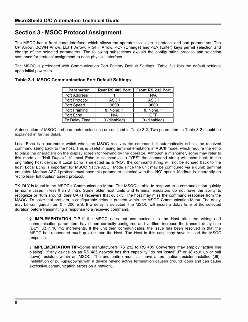
The MSOC is preloaded with Communication Port Factory Default Settings. Table 3-1 lists the default settingsupon initial power-up.
Table 3-1. MSOC Communication Port Default Settings
Parameter Rear RS 485 Port Front RS 232 PortPort Address 1 N/APort Protocol ASCII ASCIIPort Speed 9600 9600Port Framing 8, None, 1 8, None, 1Port Echo N/A OFFTx Delay Time 0 {disabled} 0 {disabled}
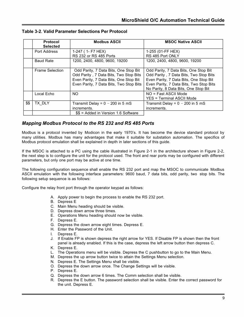
A description of MSOC port parameter selections are outlined in Table 3-2. Two parameters in Table 3-2 should beexplained in further detail.
Local Echo is a parameter which when the MSOC receives the command, it automatically echo’s the receivedcommand string back to the host. This is useful in using terminal emulators in ASCII mode, which require the echoto place the characters on the display screen for viewing by the operator. Although a misnomer, some may refer tothis mode as “Half Duplex”. If Local Echo is selected as a “YES” the command string will echo back to theoriginating host device. If Local Echo is selected as a “NO”, the command string will not be echoed back to thehost. Local Echo is important for MSOC Native ASCII Mode since the unit may be configured via a dumb terminalemulator. Modbus ASCII protocol must have this parameter selected with the “NO” option. Modbus is inherently an“echo less- full duplex” based protocol.
TX_DLY is found in the MSOC’s Communication Menu. The MSOC is able to respond to a communication quickly(in some cases in less than 3 mS). Some older host units and terminal emulators do not have the ability torecognize or “turn around” their UART receivers that quickly. The host may miss the command response from theMSOC. To solve that problem, a configurable delay is present within the MSOC Communication Menu. The delaymay be configured from 0 – 200 mS. If a delay is selected, the MSOC will insert a delay time of the selectedduration before transmitting a response to a received command.
ÿ IMPLEMENTATION TIP–If the MSOC does not communicate to the Host after the wiring andcommunication parameters have been correctly configured and verified, increase the transmit delay time(DLY TX) in 10 mS increments. If the unit then communicates, the issue has been resolved in that theMSOC has responded much quicker than the Host. The Host in this case may have missed the MSOCresponse.
ÿ IMPLEMENTATION TIP–Some manufacturers RS 232 to RS 485 Converters may employ “active linebiasing”. If any device on an RS 485 network has this capability “do not install” J7 or J8 (pull up or pulldown) resistors within an MSOC. The end unit(s) must still have a termination resistor installed (J6).Installation of pull-ups/downs with a device having active termination causes ground loops and can causeexcessive communication errors on a network.
MicroShield O/C Automation Technical Guide
9
Table 3-2. Valid Parameter Selections Per Protocol
ProtocolSelected
Modbus ASCII MSOC Native ASCII
Port Address 1-247 ( 1- F7 HEX)RS 232 or RS 485 Ports
1-255 (01-FF HEX)RS 485 Port ONLY
Baud Rate 1200, 2400, 4800, 9600, 19200 1200, 2400, 4800, 9600, 19200
Frame Selection Odd Parity, 7 Data Bits, One Stop BitOdd Parity , 7 Data Bits, Two Stop BitsEven Parity, 7 Data Bits, One Stop BitEven Parity, 7 Data Bits, Two Stop Bits
Odd Parity, 7 Data Bits, One Stop BitOdd Parity , 7 Data Bits, Two Stop BitsEven Parity, 7 Data Bits, One Stop BitEven Parity, 7 Data Bits, Two Stop BitsNo Parity, 8 Data Bits, One Stop Bit
Local Echo NO NO = Fast ASCII ModeYES = Terminal ASCII Mode
$$ TX_DLY Transmit Delay = 0 − 200 in 5 mSincrements.
Transmit Delay = 0 − 200 in 5 mSincrements.
$$ = Added in Version 1.6 Software
Mapping Modbus Protocol to the RS 232 and RS 485 Ports
Modbus is a protocol invented by Modicon in the early 1970’s. It has become the device standard protocol bymany utilities. Modbus has many advantages that make it suitable for substation automation. The specifics ofModbus protocol emulation shall be explained in depth in later sections of this guide.
If the MSOC is attached to a PC using the cable illustrated in Figure 2-1 in the architecture shown in Figure 2-2,the next step is to configure the unit for the protocol used. The front and rear ports may be configured with differentparameters, but only one port may be active at one time.
The following configuration sequence shall enable the RS 232 port and map the MSOC to communicate ModbusASCII emulation with the following interface parameters: 9600 baud, 7 data bits, odd parity, two stop bits. Thefollowing setup sequence is as follows:
Configure the relay front port through the operator keypad as follows:
A. Apply power to begin the process to enable the RS 232 port.B. Depress EC. Main Menu heading should be visible.D. Depress down arrow three times.E. Operations Menu heading should now be visible.F. Depress E.G. Depress the down arrow eight times. Depress E.H. Enter the Password of the Unit.I. Depress E.J. If Enable FP is shown depress the right arrow for YES. If Disable FP is shown then the front
panel is already enabled. If this is the case, depress the left arrow button then depress C.K. Depress E.L. The Operations menu will be visible. Depress the C pushbutton to go to the Main Menu.M. Depress the up arrow button twice to attain the Settings Menu selection.N. Depress E. The Settings Menu shall be visible.O. Depress the down arrow once. The Change Settings will be visible.P. Depress E.Q. Depress the down arrow 6 times. The Comm selection shall be visible.R. Depress the E button. The password selection shall be visible. Enter the correct password for
the unit. Depress E.
MicroShield O/C Automation Technical Guide
10
S. Select the appropriate address for the unit. For this instance it shall be 1. To change–depressE, right arrow to the correct value, depress E and then depress C.
T. Depress the down arrow once. FP Baud rate shall be visible. Select 9600. To change–depressE, right arrow to the correct value, depress E and then depress C.
U. Depress the down arrow once. FP Frm shall be visible. Select O,7,2. This sets the port to 7data bits, Odd Parity, and two stop bits. To change–depress E, right arrow to the correctvalue, depress E and then depress C.
V. Depress the down arrow once. FP Prot shall be visible. Select Modbus. This enables theModbus protocol resident in the unit. To change–depress E, right arrow to the correct value,depress E and then depress C.
W. Depress the down arrow once. RP Baud rate shall be visible. Select 9600. To change–depress E, right arrow to the correct value, depress E and then depress C.
X. Depress the down arrow once. RP Frm shall be visible. Select O,7,2. This sets the port to 7data bits, Odd Parity, and two stop bits. To change–depress E, right arrow to the correctvalue, depress E and then depress C.
Y. Depress the down arrow once. RP Prot shall be visible. Select Modbus. This enables theModbus protocol resident in the unit. To change–depress E, right arrow to the correct value,depress E and then depress C
Z. Depress the down arrow once. Local Echo shall be visible. Select OFF. These selections shallplace the unit in the native Modbus protocol mode. To change–depress E, right arrow to thecorrect value, depress E and then depress C.
AA. After each of the settings, perform a unit save to maintain the unit settings entered in thissession.
The above process has configured the front (RS 232) and the rear (RS 485) ports for Modbus communication. TheRS 232 port has been enabled for communication. Sequence steps A through L enable the front port forcommunication. It should be noted that both ports need not be configured for the same protocol.
Mapping MSOC Native ASCII Protocol
Modbus Protocol is an industry standard in the industrial sector. It has also been widely accepted in the Utilitysector. Prior to the acceptance of a de-facto protocol, each manufacturer created its own protocol. A universalmethod of communication was to send a command string to a unit in an ASCII format. An ASCII formatted protocolwas developed by ABB for the MSOC. It can be used for network connectivity as is explained in future sections ofthis document. The protocol developed by ABB to be interpreted by the MSOC shall be referred to as the MSOCNative ASCII Protocol. This section shall describe in detail the method to enable the RS 232 port and map theMSOC Native Protocol to the both the RS 232 and RS 485 ports.
To enable the MSOC Native ASCII Protocol for 8 data bits, 1 stop bit, no parity, the configuration sequence to beexecuted by the user is as follows:
A. Depress EB. Main Menu heading should be visible.C. Depress down arrow three times.D. Operations Menu heading should now be visible.E. Depress E.F. Depress the down arrow six times.G. Enter the Password of the Unit. It is assumed that the factory default is the password–depress
E.H. Depress E.I. If Enable FP is shown Depress the right arrow for YES and Depress E. If Disable FP is shown
then the front panel is already enabled. If this is the case, depress the left arrow button anddepress C.
J. Depress E.K. The Operations menu will be visible. Depress the C button to go to the Main Menu.L. Depress the up arrow button twice to attain the Settings Menu selection.
MicroShield O/C Automation Technical Guide
11
M. Depress E. The Settings Menu shall be visible.N. Depress the down arrow once. The Change Settings will be visible.O. Depress E.P. Depress the down arrow 6 times. The Comm selection shall be visible.Q. Depress the E button. The password selection shall be visible. Enter the correct password for
the unit. Then Depress E to accept the password.R. Select the appropriate address for the unit. For this instance it shall be 1. To change the
address–press E, right arrow to the proper value, depress E then depress C.S. Depress the down arrow once. FP Baud rate shall be visible. Select 9600. To change the
Baud Rate–press E, right arrow to the proper value, depress E then depress C.T. Depress the down arrow once. FP Frm shall be visible. Select 8N1. This sets the port to 8
data bits, No Parity, and one stop bit. To change the Parity–press E, right arrow to the propervalue, depress E then depress C.
U. Depress the down arrow once. FP Prot shall be visible. Select ASCII. This enables the ASCIIprotocol resident in the unit. To change the protocol–press E, right arrow to the proper value,depress E then depress C.
V. Depress the down arrow once. Local Echo shall be visible. Select OFF. To change the LocalEcho–press E, right arrow to the proper value, depress E then depress C.These selectionsshall place the unit in the native ASCII protocol mode.
W. After each of the settings, perform a unit save to maintain the unit settings entered in thissession. Depressing the C button at the main menu shall allow a setting query to be sent tothe operator. Depress the right arrow key and depress the E button to save the settings.
The functions to test connectivity shall be described in future sections within this guide.
Directing Communications Via the Front (RS 232) or Rear (RS 485) Port
As stated previously, only one port may be enabled on the MSOC at one time. Communications may be directedthrough the front RS 232 port or the rear RS 485 port. To direct the communications from the front RS 232 port tothe rear RS 485 port the following procedure must be followed in addition to the aforementioned procedure for thenative ASCII and the Modbus ASCII protocols.
A. Depress E.B. Depress the down arrow 4 times to display the Operations Menu.C. Depress E.D. Depress the down arrow 8 times to display the selection Enable FP COM.E. Depress E.F. Enter the Password as described in the previous illustrations.G. The user shall be prompted, with the selection Enable FP < >. If the selection is YES, then
the Front Port (RS 232) shall have the communications options configured via the aboveprocess. If the Selection is NO then the Rear Port (RS 485) shall be enabled with the protocolconfigured via the above process. Enter the correct password for the unit. Then depress E toaccept the password.
The above procedure has enabled the RS 485 port and disabled the RS 232 port. Selection of the Enable FP<>selection allows for the direction of the protocols selected.
NOTE: If the MSOC has its supply power removed (unit powered down) and then re-attached (unit powered up),the MSOC will Disable the front (RS 232) ports and Enable the rear (RS 485) port. If the MSOC is unit reset via thefront MMI display panel (by simultaneously depressing the “C” “E” and “Up Arrow” keys), the MSOC will alsoDisable the front (RS 232) port and Enable the rear (RS 485) port. If the operator requires communication throughthe front panel port, the above procedure must be followed to re-initialize, the RS 232 port).
MicroShield O/C Automation Technical Guide
12
Section 4 - MSOC Protocol Description
If the cable connections and front panel configuration procedures are followed implicitly, the MSOC willcommunicate with a host computer capable of transmitting and receiving the selected protocol strings. Thefollowing sections will describe the commands for Modbus ASCII and MSOC Native ASCII protocols.
Modbus Command Set
Modbus is available in two emulations, Modbus RTU and Modbus ASCII. Modbus RTU is a bit oriented protocol(normally referred to as Synchronous), and Modbus ASCII is a byte-oriented protocol (normally referred to asAsynchronous). Both emulations support the same command set. Networked nodes cannot communicateunless the same emulation of the Modbus protocol is interpreted. This is an extremely important issue. TheMSOC only supports the Modbus ASCII protocol. Modbus RTU emulation hosts cannot directly communicate to anMSOC.
Modbus ASCII Protocol
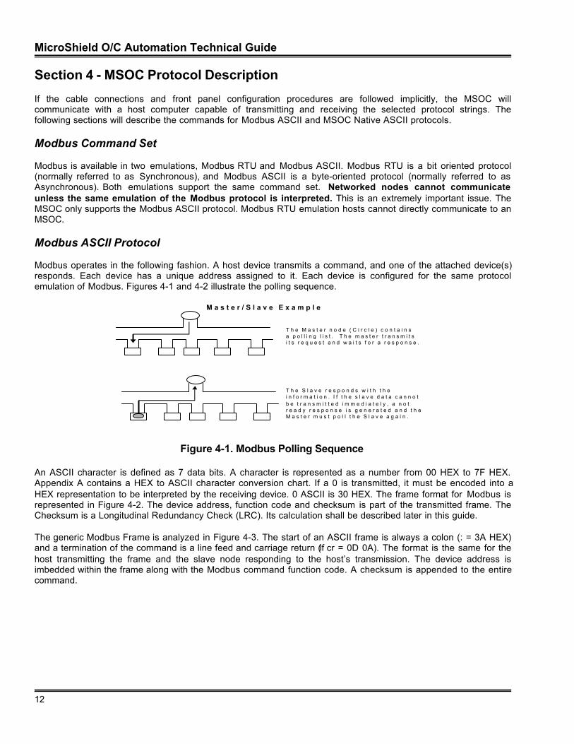
Modbus operates in the following fashion. A host device transmits a command, and one of the attached device(s)responds. Each device has a unique address assigned to it. Each device is configured for the same protocolemulation of Modbus. Figures 4-1 and 4-2 illustrate the polling sequence.
M a s t e r / S l a v e E x a m p l e
T h e M a s t e r n o d e ( C i r c l e ) c o n t a i n sa p o l l i n g l i s t . T h e m a s t e r t r a n s m i t si t s r e q u e s t a n d w a i t s f o r a r e s p o n s e .
T h e S l a v e r e s p o n d s w i t h t h ei n f o r m a t i o n . I f t h e s l a v e d a t a c a n n o tb e t r a n s m i t t e d i m m e d i a t e l y , a n o tr e a d y r e s p o n s e i s g e n e r a t e d a n d t h eM a s t e r m u s t p o l l t h e S l a v e a g a i n .
Figure 4-1. Modbus Polling Sequence
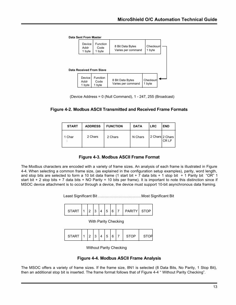
An ASCII character is defined as 7 data bits. A character is represented as a number from 00 HEX to 7F HEX.Appendix A contains a HEX to ASCII character conversion chart. If a 0 is transmitted, it must be encoded into aHEX representation to be interpreted by the receiving device. 0 ASCII is 30 HEX. The frame format for Modbus isrepresented in Figure 4-2. The device address, function code and checksum is part of the transmitted frame. TheChecksum is a Longitudinal Redundancy Check (LRC). Its calculation shall be described later in this guide.
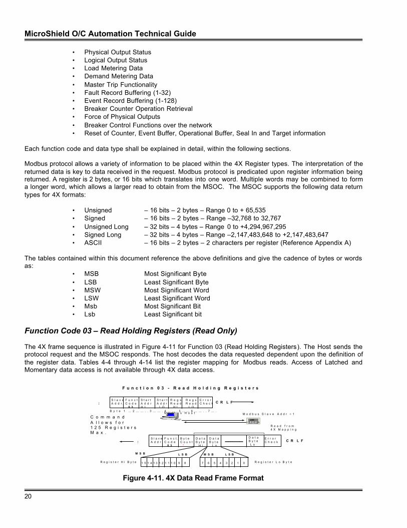
The generic Modbus Frame is analyzed in Figure 4-3. The start of an ASCII frame is always a colon (: = 3A HEX)and a termination of the command is a line feed and carriage return (lf cr = 0D 0A). The format is the same for thehost transmitting the frame and the slave node responding to the host’s transmission. The device address isimbedded within the frame along with the Modbus command function code. A checksum is appended to the entirecommand.
MicroShield O/C Automation Technical Guide
13
DeviceAddr1 byte
Function Code1 byte
8 Bit Data BytesVaries per command
Checksum1 byte
DeviceAddr1 byte
Function Code1 byte
8 Bit Data BytesVaries per command
Checksum1 byte
Data Sent From Master
Data Received From Slave
(Device Address = 0 (Null Command), 1 - 247, 255 (Broadcast)
Figure 4-2. Modbus ASCII Transmitted and Received Frame Formats
START FUNCTIONADDRESS DATA LRC END
1 Char :
2 Chars 2 Chars N Chars 2 Chars 2 CharsCR LF
Figure 4-3. Modbus ASCII Frame Format
The Modbus characters are encoded with a variety of frame sizes. An analysis of each frame is illustrated in Figure4-4. When selecting a common frame size, (as explained in the configuration setup examples), parity, word length,and stop bits are selected to form a 10 bit data frame (1 start bit + 7 data bits + 1 stop bit + 1 Parity bit “OR” 1start bit + 2 stop bits + 7 data bits + NO Parity = 10 bits per frame). It is important to note this distinction since ifMSOC device attachment is to occur through a device, the device must support 10-bit asynchronous data framing.
Least Significant Bit ………………………….…Most Significant Bit
START 1 2 3 4 5 6 7 PARITY STOP
With Parity Checking
START 1 2 3 4 5 6 7 STOP STOP
Without Parity Checking
Figure 4-4. Modbus ASCII Frame Analysis
The MSOC offers a variety of frame sizes. If the frame size, 8N1 is selected (8 Data Bits, No Parity, 1 Stop Bit),then an additional stop bit is inserted. The frame format follows that of Figure 4-4 “ Without Parity Checking”.
MicroShield O/C Automation Technical Guide
14
ÿ IMPLEMENTATION TIP-When Commissioning a Modbus system, it is always advisable to connect acommunication analyzer in-line with the Host. It is always uncertain whether the Host is sending thecommand correctly. Within the MSOC, an incorrect address request will always generate an exceptionresponse from the relay. If an exception response is generated, many Host devices will not display theModbus exception response generated by the unit. A communication analyzer allows for rapidtroubleshooting of a malfunctioning network connection.
The MSOC emulates a slave device. The following Modbus Commands are supported within the unit:
• 01 – Read 0X Coil Status• 02 – Read 1X Contact Status• 03 – Read 4X Holding Registers• 16 – Write 4X Holding Registers• 23 – Write 4X and Read 4X Holding Registers• 20 – Read 6X Extended Registers• 21 – Write 6X Extended Registers
Any other Modbus command sent to the MSOC shall result in a Modbus exception code being sent to thetransmitting device. The following sections will further describe the Modbus functionality within the MSOC.
ÿ IMPLEMENTATION TIP-Although the MSOC allows configuration of Modbus for a frame of N-8-1, someimplementations will interpret this emulation of Modbus to be RTU mode. The MSOC does not support thismode. It is advisable to contact the manufacturer of the Host and Host software to determine theinterpretation of the command string. For example, the Modicon XMIT and COMM block allowing the PLCto emulate a Host device only allows block frame size designation of 7 data bits.
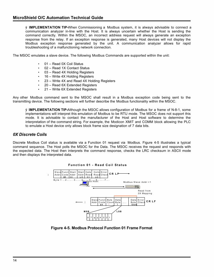
0X Discrete Coils
Discrete Modbus Coil status is available via a Function 01 request via Modbus. Figure 4-5 illustrates a typicalcommand sequence. The Host polls the MSOC for the Data. The MSOC receives the request and responds withthe expected data. The Host then interprets the command response, checks the LRC checksum in ASCII modeand then displays the interpreted data.
F u n c t i o n 0 1 - R e a d C o i l S t a t u s
M o d b u s H o s t
EC
M o d b u s S l a v e A d d r = 1
R e a d f r o m 0 X M a p p i n g
S l a v eA d d r.
F u n c t .C o d e 01
Sta r tA d d rH I
S ta r t A d d r L O
CoilsR e a d H I
C o i l sR e a d LO
E r r o rC h e c k C R L F:
S laveA d d r .
F u n c t .C o d e 0 1
By teC o u n t *
D a t aBy te 1
… . .D a t aBy te N N N
E r r o rC h e c k C R L F:
B y t e 1 … 2 … … . . 3 … … . 4 … … . 5 … … 6 … … . . 7 … .
M S B L S B
8 7 6 5 4 3 2 1
Figure 4-5. Modbus Protocol Function 01 Frame Format
MicroShield O/C Automation Technical Guide
15
Function Code 1 (Read Coil Status) – Read Only Data
The 0X read command allows for access of Logical and Physical Input data. The information listed in Tables 3-1,3-2, and 4-1 is that which is reported in real time. In other words, if the bits are polled as per the table, the status ofeach data bit is reported at the time the data is requested. If the data is momentary in nature, then access of statusis dependent upon reading the information at the time the function or signal is present.
Table 4-2 lists the Latched Data reported by the MSOC. This data is only available in 0X coil access. It is notavailable in 1X or 4X data format types.
Momentary data reporting is not available at the present time. The data within the 0X discretes are also availablein 4X memory for those hosts, which are not able to access this data type.
If data is requested from memory addresses not defined within this document, a Modbus Exception Code shall begenerated.
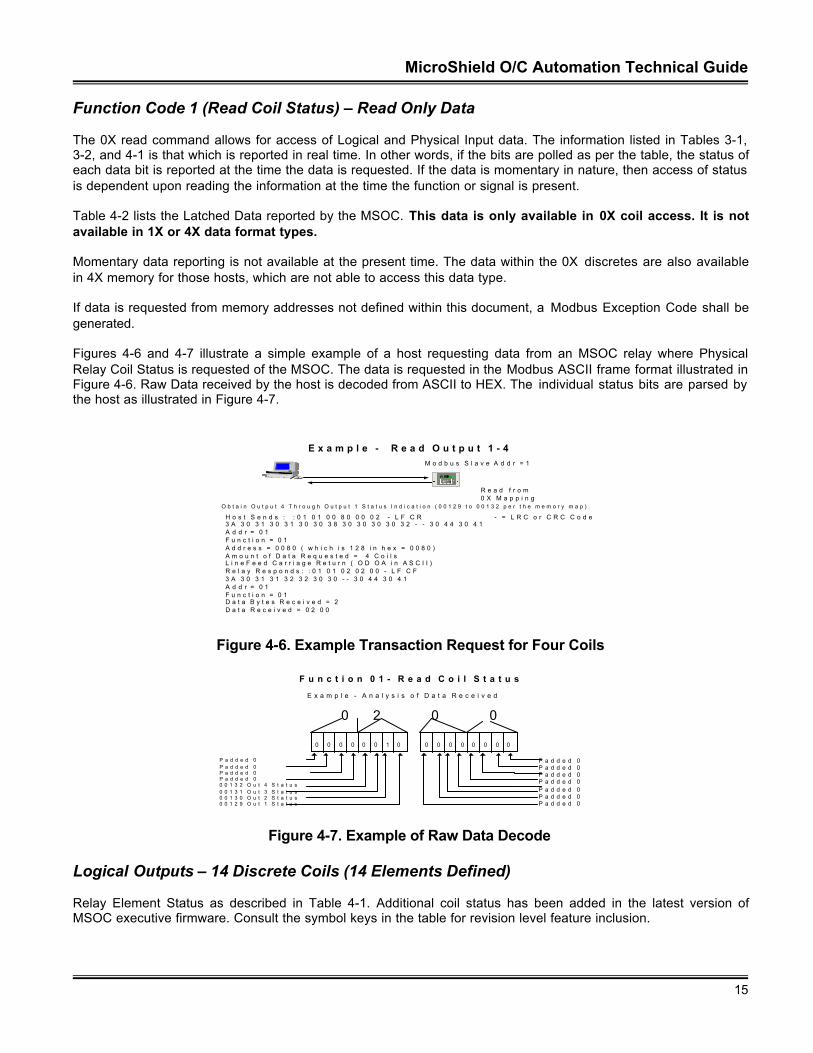
Figures 4-6 and 4-7 illustrate a simple example of a host requesting data from an MSOC relay where PhysicalRelay Coil Status is requested of the MSOC. The data is requested in the Modbus ASCII frame format illustrated inFigure 4-6. Raw Data received by the host is decoded from ASCII to HEX. The individual status bits are parsed bythe host as illustrated in Figure 4-7.
E x a m p l e - R e a d O u t p u t 1 - 4
O b t a i n O u t p u t 4 T h r o u g h O u t p u t 1 S t a t u s I n d i c a t i o n ( 0 0 1 2 9 t o 0 0 1 3 2 p e r t h e m e m o r y m a p ) .
H o s t S e n d s : : 0 1 0 1 0 0 8 0 0 0 0 2 - L F C R - = L R C o r C R C C o d e3 A 3 0 3 1 3 0 3 1 3 0 3 0 3 8 3 0 3 0 3 0 3 0 3 2 - - 3 0 4 4 3 0 4 1A d d r = 0 1F u n c t i o n = 0 1A d d r e s s = 0 0 8 0 ( w h i c h i s 1 2 8 i n h e x = 0 0 8 0 )A m o u n t o f D a t a R e q u e s t e d = 4 C o i l sL i n e F e e d C a r r i a g e R e t u r n ( O D O A i n A S C I I )R e l a y R e s p o n d s : : 0 1 0 1 0 2 0 2 0 0 - L F C F3 A 3 0 3 1 3 1 3 2 3 2 3 0 3 0 - - 3 0 4 4 3 0 4 1A d d r = 0 1F u n c t i o n = 0 1D a t a B y t e s R e c e i v e d = 2D a t a R e c e i v e d = 0 2 0 0
M o d b u s S l a v e A d d r = 1
R e a d f r o m 0 X M a p p i n g
E
C
N e t w o r kP a r t n e rV1.0
Figure 4-6. Example Transaction Request for Four Coils
F u n c t i o n 0 1 - R e a d C o i l S t a t u s
0 0 0 0 0 0 1 0 0 0 0 0 0 0 0 0
E x a m p l e - A n a l y s i s o f D a t a R e c e i v e d
0 2 0 0
P a d d e d 0P a d d e d 0P a d d e d 0P a d d e d 00 0 1 3 2 O u t 4 S t a t u s0 0 1 3 1 O u t 3 S t a t u s0 0 1 3 0 O u t 2 S t a t u s0 0 1 2 9 O u t 1 S t a t u s
P a d d e d 0P a d d e d 0P a d d e d 0P a d d e d 0P a d d e d 0P a d d e d 0P a d d e d 0
Figure 4-7. Example of Raw Data Decode
Logical Outputs – 14 Discrete Coils (14 Elements Defined)
Relay Element Status as described in Table 4-1. Additional coil status has been added in the latest version ofMSOC executive firmware. Consult the symbol keys in the table for revision level feature inclusion.
MicroShield O/C Automation Technical Guide
16
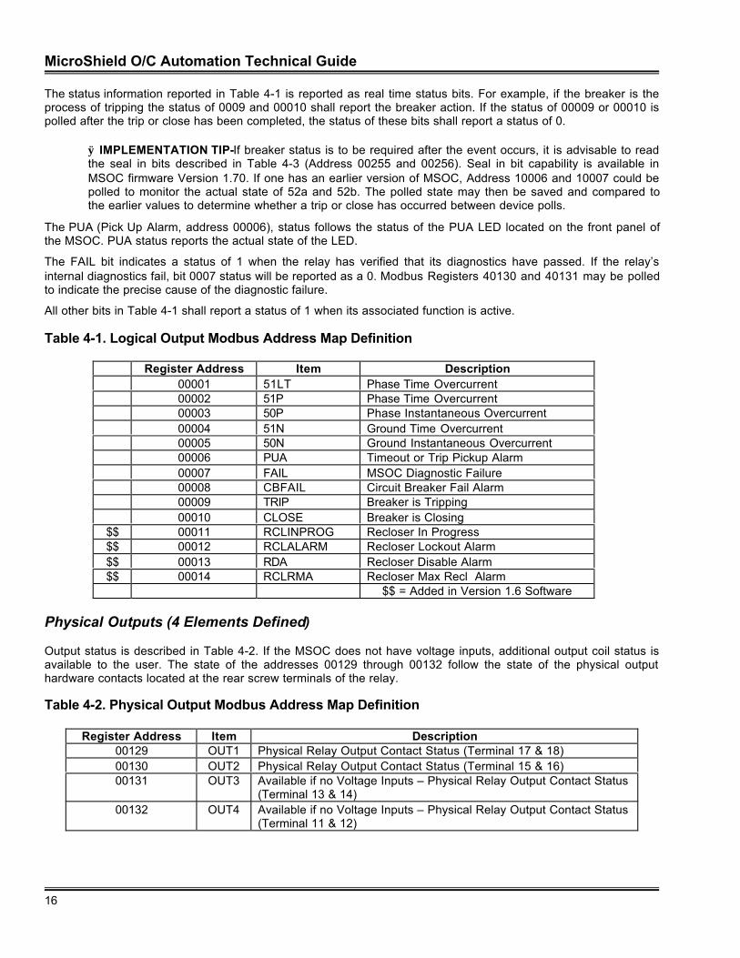
The status information reported in Table 4-1 is reported as real time status bits. For example, if the breaker is theprocess of tripping the status of 0009 and 00010 shall report the breaker action. If the status of 00009 or 00010 ispolled after the trip or close has been completed, the status of these bits shall report a status of 0.
ÿ IMPLEMENTATION TIP-If breaker status is to be required after the event occurs, it is advisable to readthe seal in bits described in Table 4-3 (Address 00255 and 00256). Seal in bit capability is available inMSOC firmware Version 1.70. If one has an earlier version of MSOC, Address 10006 and 10007 could bepolled to monitor the actual state of 52a and 52b. The polled state may then be saved and compared tothe earlier values to determine whether a trip or close has occurred between device polls.
The PUA (Pick Up Alarm, address 00006), status follows the status of the PUA LED located on the front panel ofthe MSOC. PUA status reports the actual state of the LED.
The FAIL bit indicates a status of 1 when the relay has verified that its diagnostics have passed. If the relay’sinternal diagnostics fail, bit 0007 status will be reported as a 0. Modbus Registers 40130 and 40131 may be polledto indicate the precise cause of the diagnostic failure.
All other bits in Table 4-1 shall report a status of 1 when its associated function is active.
Table 4-1. Logical Output Modbus Address Map Definition
Register Address Item Description00001 51LT Phase Time Overcurrent00002 51P Phase Time Overcurrent00003 50P Phase Instantaneous Overcurrent00004 51N Ground Time Overcurrent00005 50N Ground Instantaneous Overcurrent00006 PUA Timeout or Trip Pickup Alarm00007 FAIL MSOC Diagnostic Failure00008 CBFAIL Circuit Breaker Fail Alarm00009 TRIP Breaker is Tripping00010 CLOSE Breaker is Closing
$$ 00011 RCLINPROG Recloser In Progress$$ 00012 RCLALARM Recloser Lockout Alarm$$ 00013 RDA Recloser Disable Alarm$$ 00014 RCLRMA Recloser Max Recl Alarm
$$ = Added in Version 1.6 Software
Physical Outputs (4 Elements Defined)
Output status is described in Table 4-2. If the MSOC does not have voltage inputs, additional output coil status isavailable to the user. The state of the addresses 00129 through 00132 follow the state of the physical outputhardware contacts located at the rear screw terminals of the relay.
Table 4-2. Physical Output Modbus Address Map Definition
Register Address Item Description00129 OUT1 Physical Relay Output Contact Status (Terminal 17 & 18)00130 OUT2 Physical Relay Output Contact Status (Terminal 15 & 16)00131 OUT3 Available if no Voltage Inputs – Physical Relay Output Contact Status
(Terminal 13 & 14)00132 OUT4 Available if no Voltage Inputs – Physical Relay Output Contact Status
(Terminal 11 & 12)
MicroShield O/C Automation Technical Guide
17
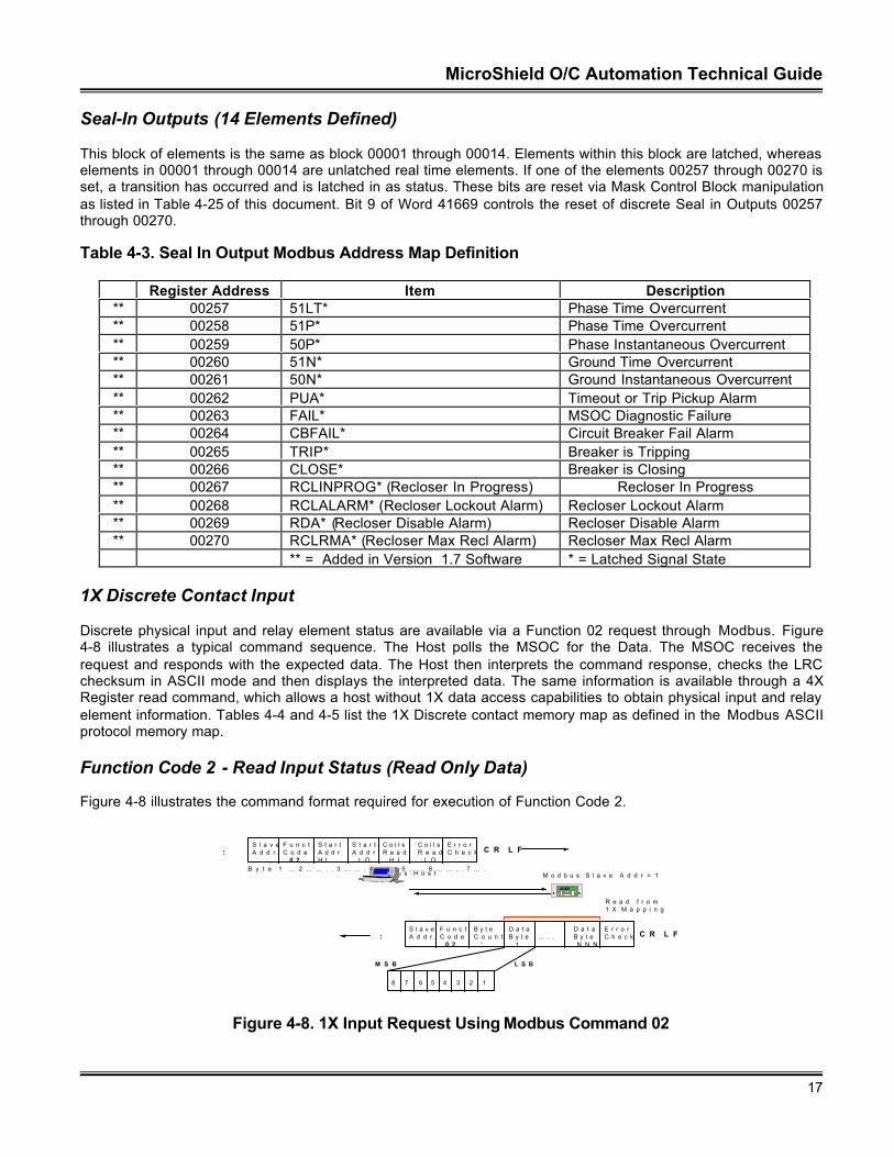
Seal-In Outputs (14 Elements Defined)
This block of elements is the same as block 00001 through 00014. Elements within this block are latched, whereaselements in 00001 through 00014 are unlatched real time elements. If one of the elements 00257 through 00270 isset, a transition has occurred and is latched in as status. These bits are reset via Mask Control Block manipulationas listed in Table 4-25 of this document. Bit 9 of Word 41669 controls the reset of discrete Seal in Outputs 00257through 00270.
Table 4-3. Seal In Output Modbus Address Map Definition
Register Address Item Description** 00257 51LT* Phase Time Overcurrent** 00258 51P* Phase Time Overcurrent** 00259 50P* Phase Instantaneous Overcurrent** 00260 51N* Ground Time Overcurrent** 00261 50N* Ground Instantaneous Overcurrent** 00262 PUA* Timeout or Trip Pickup Alarm** 00263 FAIL* MSOC Diagnostic Failure** 00264 CBFAIL* Circuit Breaker Fail Alarm** 00265 TRIP* Breaker is Tripping** 00266 CLOSE* Breaker is Closing** 00267 RCLINPROG* (Recloser In Progress) Recloser In Progress** 00268 RCLALARM* (Recloser Lockout Alarm) Recloser Lockout Alarm** 00269 RDA* (Recloser Disable Alarm) Recloser Disable Alarm** 00270 RCLRMA* (Recloser Max Recl Alarm) Recloser Max Recl Alarm
** = Added in Version 1.7 Software * = Latched Signal State
1X Discrete Contact Input
Discrete physical input and relay element status are available via a Function 02 request through Modbus. Figure4-8 illustrates a typical command sequence. The Host polls the MSOC for the Data. The MSOC receives therequest and responds with the expected data. The Host then interprets the command response, checks the LRCchecksum in ASCII mode and then displays the interpreted data. The same information is available through a 4XRegister read command, which allows a host without 1X data access capabilities to obtain physical input and relayelement information. Tables 4-4 and 4-5 list the 1X Discrete contact memory map as defined in the Modbus ASCIIprotocol memory map.
Function Code 2 - Read Input Status (Read Only Data)
Figure 4-8 illustrates the command format required for execution of Function Code 2.
M o d b u s H o s t M o d b u s S l a v e A d d r = 1
R e a d f r o m 1 X M a p p i n g
S l a v eA d d r .
F u n c t .C o d e 0 2
S t a r tA d d rH I
S t a r t A d d r L O
C o i l sR e a d H I
C o i l sR e a d L O
E r r o rC h e c k C R L F:
S l a v eA d d r .
F u n c t .C o d e 0 2
B y t eC o u n t *
D a t aB y t e 1
… . .D a t aB y t e N N N
E r r o rC h e c k C R L F:
B y t e 1 … 2 … … . . 3 … … . 4 … … . 5 … … 6 … … . . 7 … .
M S B L S B
8 7 6 5 4 3 2 1
E
C
N e t w o r kP a r t n e rV 1 . 0
Figure 4-8. 1X Input Request Using Modbus Command 02
MicroShield O/C Automation Technical Guide
18
It should be noted that every MSOC allows for real time status reporting when the unit is polled. If a status ismomentary and is missed during the host poll, then the data is lost. Momentary data reporting is not available. Itshould also be noted that data requested from 1X data address ranges not defined within this document shouldgenerate Modbus exception codes.
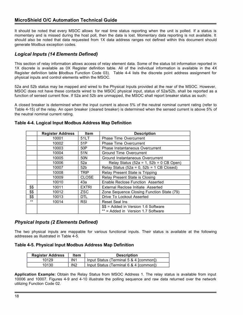
Logical Inputs (14 Elements Defined)
This section of relay information allows access of relay element data. Some of the status bit information reported in1X discrete is available as 0X Register definition table. All of the individual information is available in the 4XRegister definition table (Modbus Function Code 03). Table 4-4 lists the discrete point address assignment forphysical inputs and control elements within the MSOC.
52a and 52b status may be mapped and wired to the Physical Inputs provided at the rear of the MSOC. However,MSOC does not have these contacts wired to the MSOC physical input, status of 52a/52b, shall be reported as afunction of sensed current flow. If 52a and 52b are unmapped, the MSOC shall report breaker status as such:
A closed breaker is determined when the input current is above 5% of the neutral nominal current rating (refer toTable 4-15) of the relay. An open breaker (cleared breaker) is determined when the sensed current is above 5% ofthe neutral nominal current rating.
Table 4-4. Logical Input Modbus Address Map Definition
Register Address Item Description10001 51LT Phase Time Overcurrent10002 51P Phase Time Overcurrent10003 50P Phase Instantaneous Overcurrent10004 51N Ground Time Overcurrent10005 50N Ground Instantaneous Overcurrent10006 52a Relay Status (52a = 1, 52b = 0 CB Open)10007 52b Relay Status (52a = 0, 52b = 1 CB Closed)10008 TRIP Relay Present State is Tripping10009 CLOSE Relay Present State is Closing10010 43a Enable Reclose Function Asserted
$$ 10011 EXTRI External Reclose Initiate Asserted$$ 10012 ZSC Zone Sequence Closing Function State (79)$$ 10013 DTL Drive To Lockout Asserted** 10014 RSI Reset Seal Ins
$$ = Added in Version 1.6 Software** = Added in Version 1.7 Software
Physical Inputs (2 Elements Defined)
The two physical inputs are mappable for various functional inputs. Their status is available at the followingaddresses as illustrated in Table 4-5.
Table 4-5. Physical Input Modbus Address Map Definition
Register Address Item Description10129 IN1 Input Status (Terminal 5 & 4 [common])10130 IN2 Input Status (Terminal 6 & 4 [common])
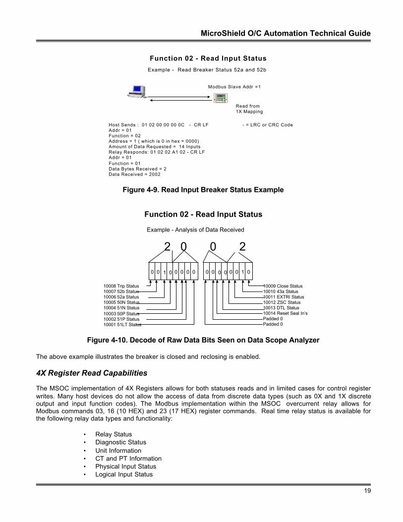
Application Example: Obtain the Relay Status from MSOC Address 1. The relay status is available from input10006 and 10007. Figures 4-9 and 4-10 illustrate the polling sequence and raw data returned over the networkutilizing Function Code 02.
MicroShield O/C Automation Technical Guide
19
Function 02 - Read Input Status
Example - Read Breaker Status 52a and 52b
Modbus Slave Addr =1
Read from 1X Mapping
Host Sends : 01 02 00 00 00 0C - CR LF - = LRC or CRC CodeAddr = 01Function = 02 Address = 1 ( which is 0 in hex = 0000)Amount of Data Requested = 14 InputsRelay Responds: 01 02 02 A1 02 - CR LFAddr = 01Function = 01Data Bytes Received = 2Data Received = 2002
E
C
N e t w o r kPartnerV1.0
Figure 4-9. Read Input Breaker Status Example
Function 02 - Read Input Status
0 0 1 0 0 0 0 0 0 0 0 0 0 0 1 0
Example - Analysis of Data Received
2 0 0 2
10008 Trip Status10007 52b Status10006 52a Status10005 50N Status10004 51N Status10003 50P Status10002 51P Status10001 51LT Status
10009 Close Status10010 43a Status10011 EXTRI Status10012 ZSC Status10013 DTL Status10014 Reset Seal In’sPadded 0Padded 0
Figure 4-10. Decode of Raw Data Bits Seen on Data Scope Analyzer
The above example illustrates the breaker is closed and reclosing is enabled.
4X Register Read Capabilities
The MSOC implementation of 4X Registers allows for both statuses reads and in limited cases for control registerwrites. Many host devices do not allow the access of data from discrete data types (such as 0X and 1X discreteoutput and input function codes). The Modbus implementation within the MSOC overcurrent relay allows forModbus commands 03, 16 (10 HEX) and 23 (17 HEX) register commands. Real time relay status is available forthe following relay data types and functionality:
• Relay Status• Diagnostic Status• Unit Information• CT and PT Information• Physical Input Status• Logical Input Status
MicroShield O/C Automation Technical Guide
20
• Physical Output Status• Logical Output Status• Load Metering Data• Demand Metering Data• Master Trip Functionality• Fault Record Buffering (1-32)• Event Record Buffering (1-128)• Breaker Counter Operation Retrieval• Force of Physical Outputs• Breaker Control Functions over the network• Reset of Counter, Event Buffer, Operational Buffer, Seal In and Target information
Each function code and data type shall be explained in detail, within the following sections.
Modbus protocol allows a variety of information to be placed within the 4X Register types. The interpretation of thereturned data is key to data received in the request. Modbus protocol is predicated upon register information beingreturned. A register is 2 bytes, or 16 bits which translates into one word. Multiple words may be combined to forma longer word, which allows a larger read to obtain from the MSOC. The MSOC supports the following data returntypes for 4X formats:
• Unsigned – 16 bits – 2 bytes – Range 0 to + 65,535• Signed – 16 bits – 2 bytes – Range –32,768 to 32,767• Unsigned Long – 32 bits – 4 bytes – Range 0 to +4,294,967,295• Signed Long – 32 bits – 4 bytes – Range –2,147,483,648 to +2,147,483,647• ASCII – 16 bits – 2 bytes – 2 characters per register (Reference Appendix A)
The tables contained within this document reference the above definitions and give the cadence of bytes or wordsas:
• MSB Most Significant Byte• LSB Least Significant Byte• MSW Most Significant Word• LSW Least Significant Word• Msb Most Significant Bit• Lsb Least Significant bit
Function Code 03 – Read Holding Registers (Read Only)
The 4X frame sequence is illustrated in Figure 4-11 for Function 03 (Read Holding Registers). The Host sends theprotocol request and the MSOC responds. The host decodes the data requested dependent upon the definition ofthe register data. Tables 4-4 through 4-14 list the register mapping for Modbus reads. Access of Latched andMomentary data access is not available through 4X data access.
F u n c t i o n 0 3 - R e a d H o l d i n g R e g i s t e r s
M o d b u s H o s t M o d b u s S l a v e A d d r = 1
R e a d f r o m 4 X M a p p i n g
S l a v eA d d r .
F u n c t .C o d e 0 3
S t a r tA d d rH I
S t a r t A d d r L O
R e g sR e a d H I
R e g sR e a d L O
E r r o rC h e c k C R L F:
B y t e 1 … 2 … … . . 3 … … . 4 … … . 5 … … 6 … … . . 7 … .
R e g i s t e r L o B y t e
C o m m a n dA l l o w s f o r1 2 5 R e g i s t e r sM a x .
S l a v eA d d r .
F u n c t .C o d e 0 3
B y t eC o u n t *
D a t aB y t e H i
D a t aB y t e L o
D a t aB y t e L o
E r r o rC h e c k C R L F:
M S B L S B
1 5 1 4 1 3 1 2 1 1 1 0 9 8 7 6 5 4 3 2 1 0
M S B L S B
R e g i s t e r H i B y t e
E
C
N e t w o r kP a r t n e rV 1 . 0
Figure 4-11. 4X Data Read Frame Format
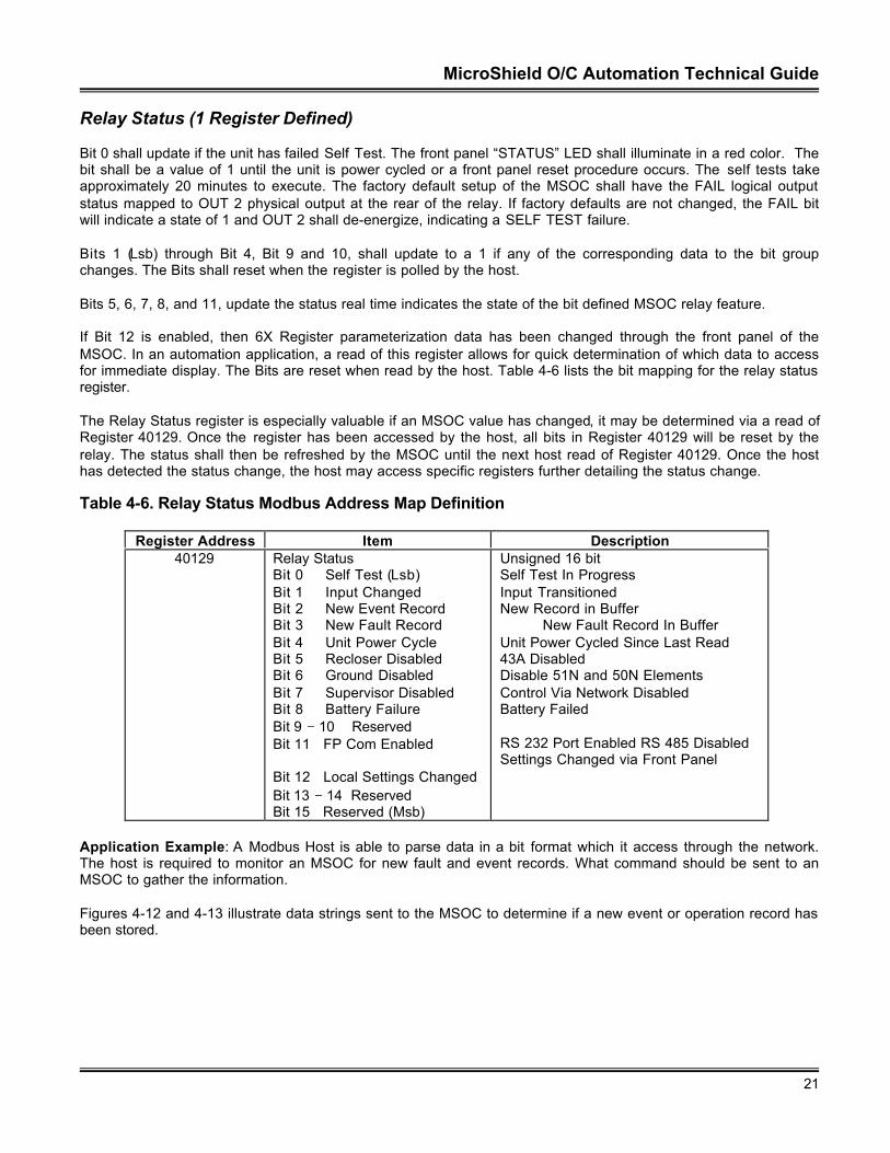
MicroShield O/C Automation Technical Guide
21
Relay Status (1 Register Defined)
Bit 0 shall update if the unit has failed Self Test. The front panel “STATUS” LED shall illuminate in a red color. Thebit shall be a value of 1 until the unit is power cycled or a front panel reset procedure occurs. The self tests takeapproximately 20 minutes to execute. The factory default setup of the MSOC shall have the FAIL logical outputstatus mapped to OUT 2 physical output at the rear of the relay. If factory defaults are not changed, the FAIL bitwill indicate a state of 1 and OUT 2 shall de-energize, indicating a SELF TEST failure.
Bits 1 (Lsb) through Bit 4, Bit 9 and 10, shall update to a 1 if any of the corresponding data to the bit groupchanges. The Bits shall reset when the register is polled by the host.
Bits 5, 6, 7, 8, and 11, update the status real time indicates the state of the bit defined MSOC relay feature.
If Bit 12 is enabled, then 6X Register parameterization data has been changed through the front panel of theMSOC. In an automation application, a read of this register allows for quick determination of which data to accessfor immediate display. The Bits are reset when read by the host. Table 4-6 lists the bit mapping for the relay statusregister.
The Relay Status register is especially valuable if an MSOC value has changed, it may be determined via a read ofRegister 40129. Once the register has been accessed by the host, all bits in Register 40129 will be reset by therelay. The status shall then be refreshed by the MSOC until the next host read of Register 40129. Once the hosthas detected the status change, the host may access specific registers further detailing the status change.
Table 4-6. Relay Status Modbus Address Map Definition
Register Address Item Description40129 Relay Status
Bit 0 Self Test (Lsb)Bit 1 Input ChangedBit 2 New Event RecordBit 3 New Fault RecordBit 4 Unit Power CycleBit 5 Recloser DisabledBit 6 Ground DisabledBit 7 Supervisor DisabledBit 8 Battery FailureBit 9 − 10 ReservedBit 11 FP Com Enabled
Bit 12 Local Settings ChangedBit 13 − 14 ReservedBit 15 Reserved (Msb)
Unsigned 16 bitSelf Test In ProgressInput TransitionedNew Record in Buffer
New Fault Record In BufferUnit Power Cycled Since Last Read43A DisabledDisable 51N and 50N ElementsControl Via Network DisabledBattery Failed
RS 232 Port Enabled RS 485 DisabledSettings Changed via Front Panel
Application Example: A Modbus Host is able to parse data in a bit format which it access through the network.The host is required to monitor an MSOC for new fault and event records. What command should be sent to anMSOC to gather the information.
Figures 4-12 and 4-13 illustrate data strings sent to the MSOC to determine if a new event or operation record hasbeen stored.
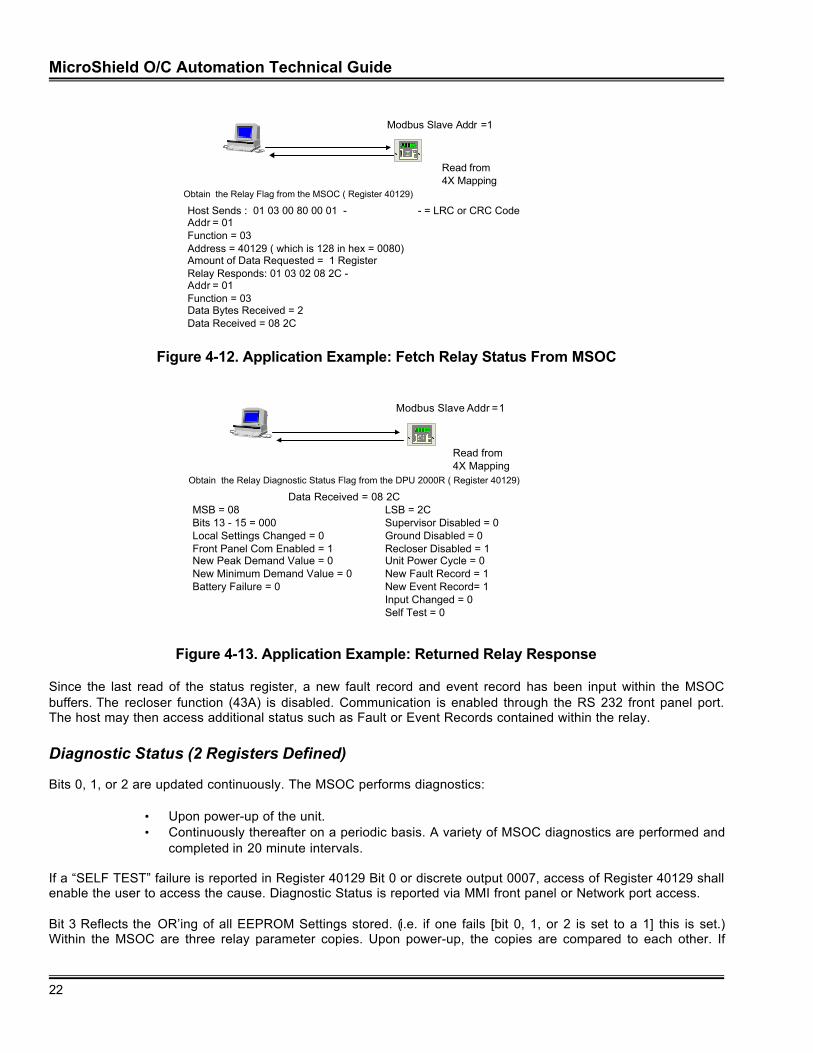
MicroShield O/C Automation Technical Guide
22
Modbus Slave Addr =1
Read from 4X Mapping
Obtain the Relay Flag from the MSOC ( Register 40129)
Host Sends : 01 03 00 80 00 01 - - = LRC or CRC CodeAddr = 01Function = 03Address = 40129 ( which is 128 in hex = 0080)Amount of Data Requested = 1 RegisterRelay Responds: 01 03 02 08 2C -Addr = 01Function = 03Data Bytes Received = 2Data Received = 08 2C
E
C
NetworkPartnerV1.0
Figure 4-12. Application Example: Fetch Relay Status From MSOC
Modbus Slave Addr =1
Read from 4X Mapping
Obtain the Relay Diagnostic Status Flag from the DPU 2000R ( Register 40129)
Data Received = 08 2CMSB = 08 LSB = 2CBits 13 - 15 = 000 Supervisor Disabled = 0Local Settings Changed = 0 Ground Disabled = 0Front Panel Com Enabled = 1 Recloser Disabled = 1New Peak Demand Value = 0 Unit Power Cycle = 0New Minimum Demand Value = 0 New Fault Record = 1Battery Failure = 0 New Event Record= 1
Input Changed = 0Self Test = 0
E
C
NetworkPartnerV1.0
Figure 4-13. Application Example: Returned Relay Response
Since the last read of the status register, a new fault record and event record has been input within the MSOCbuffers. The recloser function (43A) is disabled. Communication is enabled through the RS 232 front panel port.The host may then access additional status such as Fault or Event Records contained within the relay.
Diagnostic Status (2 Registers Defined)
Bits 0, 1, or 2 are updated continuously. The MSOC performs diagnostics:
• Upon power-up of the unit.• Continuously thereafter on a periodic basis. A variety of MSOC diagnostics are performed and
completed in 20 minute intervals.
If a “SELF TEST” failure is reported in Register 40129 Bit 0 or discrete output 0007, access of Register 40129 shallenable the user to access the cause. Diagnostic Status is reported via MMI front panel or Network port access.
Bit 3 Reflects the OR’ing of all EEPROM Settings stored. (i.e. if one fails [bit 0, 1, or 2 is set to a 1] this is set.)Within the MSOC are three relay parameter copies. Upon power-up, the copies are compared to each other. If
MicroShield O/C Automation Technical Guide
23
there is a miscompute, an MSOC PROM Failure is logged. Bit 3 is set when the unit failures to successfully readfrom all three copies of the Stored Parameters.
Bits 0 through 3 are cleared only at a unit Power On Reset, or a unit MSOC reset through the front panel.
ÿ IMPLEMENTATION TIP- Front panel reset is accomplished by pressing the “C”, “E”, and “UP arrowkeys” simultaneously on the front MMI panel of the MSOC.
The bit shall indicate 1 for diagnostic failure indication. These bits show the status.
Table 4-7. Diagnostic Status Modbus Address Map Definition
Register Address Item Description40130 Main CPU Diag. Status
Bit 0 MramFailure (Lsb)Bit 1 MepromFailureBit 2 Clock FailureBit 3 MEEPromFailureBit 4 − 14 ReservedBit 15 Reserved (Msb)
Unsigned 16 BitMain CPU RAM FAILUREChecksum Failure on EPROMIf Clock Enabled, Clock update error.MEEP Checksum Failure on refresh or read.
40131 Reserved Reserved
Unit Information (15 Registers Defined)
Unit information status allows retrieval of MSOC Executive firmware revision numbers; MSOC Catalog numbers aswell as MSOC Unit Serial numbers. The MSOC has the use of only one communication port; access of Register40143 allows a remote host to determine which port is designated for use. Two of the registers within the unitinformation block are scaled, 40140 and 40141. The returned unsigned 16 bit data values when divided by 100 willmirror the revision numbers as seen on the front LCD panel within the Unit Information menu of the MSOC. Theseare the only scaled registers within this block of 4X Registers available for read. Table 4-8 further defines the UnitInformation status block.
Table 4-8. Unit Information Status Modbus Address Map Definition
Register Address Item Description40132 Catalog Number (MSW) ASCII – 2 Characters (Leftmost Digits)40133 Catalog Number ASCII – 2 Characters40134 Catalog Number ASCII – 2 Characters40135 Catalog Number ASCII – 2 Characters40136 Catalog Number ASCII – 2 Characters40137 Catalog Number ASCII – 2 Characters40138 Catalog Number ASCII – 2 Characters40139 Catalog Number (LSW) ASCII – 2 Characters (Rightmost Digits)40140 MainCPUSwVersionNumber Unsigned 16 Bit – (Scale Factor 100)40141 AuxCPUSwVersionNumber Unsigned 16 Bit – (Scale Factor 100)40142 Protocol Unsigned 16 Bit
0 = Modbus ASCII, 1 = ASCII40143 Active Port Unsigned 16 Bit
0 = Rear RS485 Port, 1 = Front RS232 Port40144 Serial Number ASCII – 2 Characters (Leftmost Digits)40145 Serial Number ASCII – 2 Characters40146 Serial Number ASCII – 2 Characters (Rightmost Digits)
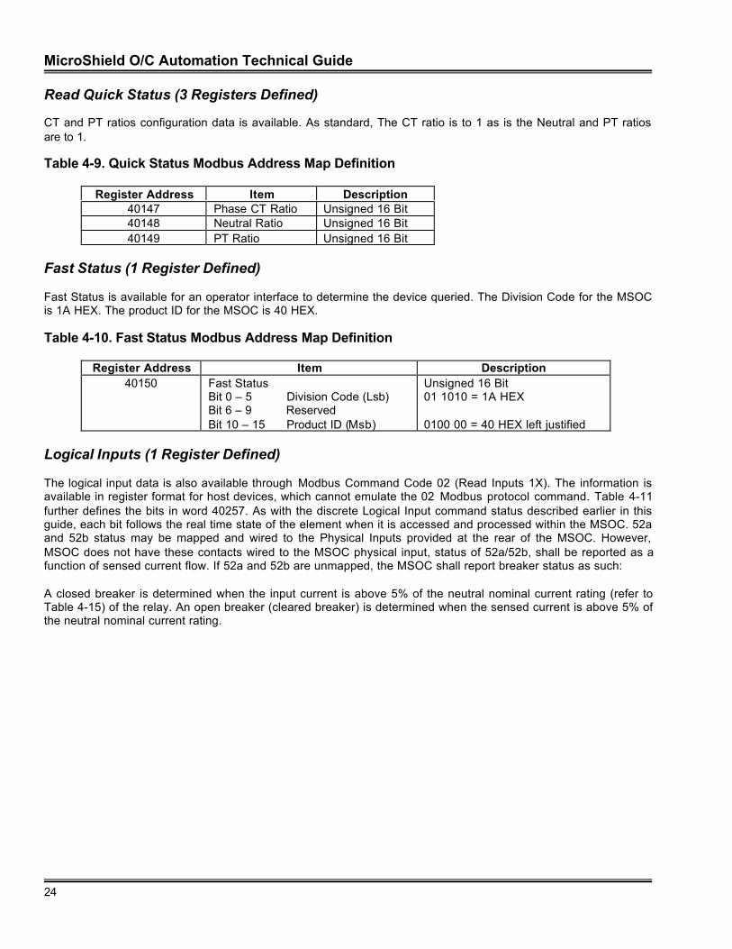
MicroShield O/C Automation Technical Guide
24
Read Quick Status (3 Registers Defined)
CT and PT ratios configuration data is available. As standard, The CT ratio is to 1 as is the Neutral and PT ratiosare to 1.
Table 4-9. Quick Status Modbus Address Map Definition
Register Address Item Description40147 Phase CT Ratio Unsigned 16 Bit40148 Neutral Ratio Unsigned 16 Bit40149 PT Ratio Unsigned 16 Bit
Fast Status (1 Register Defined)
Fast Status is available for an operator interface to determine the device queried. The Division Code for the MSOCis 1A HEX. The product ID for the MSOC is 40 HEX.
Table 4-10. Fast Status Modbus Address Map Definition
Register Address Item Description40150 Fast Status
Bit 0 – 5 Division Code (Lsb)Bit 6 – 9 ReservedBit 10 – 15 Product ID (Msb)
Unsigned 16 Bit01 1010 = 1A HEX
0100 00 = 40 HEX left justified
Logical Inputs (1 Register Defined)
The logical input data is also available through Modbus Command Code 02 (Read Inputs 1X). The information isavailable in register format for host devices, which cannot emulate the 02 Modbus protocol command. Table 4-11further defines the bits in word 40257. As with the discrete Logical Input command status described earlier in thisguide, each bit follows the real time state of the element when it is accessed and processed within the MSOC. 52aand 52b status may be mapped and wired to the Physical Inputs provided at the rear of the MSOC. However,MSOC does not have these contacts wired to the MSOC physical input, status of 52a/52b, shall be reported as afunction of sensed current flow. If 52a and 52b are unmapped, the MSOC shall report breaker status as such:
A closed breaker is determined when the input current is above 5% of the neutral nominal current rating (refer toTable 4-15) of the relay. An open breaker (cleared breaker) is determined when the sensed current is above 5% ofthe neutral nominal current rating.
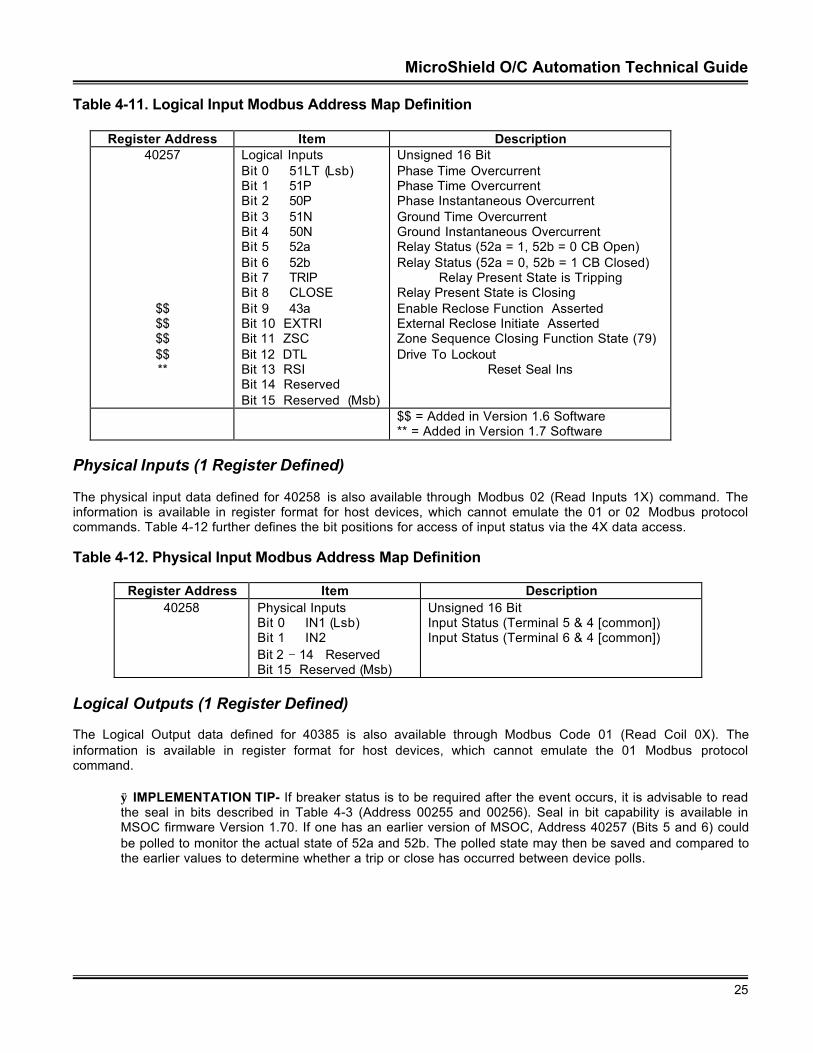
MicroShield O/C Automation Technical Guide
25
Table 4-11. Logical Input Modbus Address Map Definition
Register Address Item Description40257
$$$$$$$$**
Logical InputsBit 0 51LT (Lsb)Bit 1 51PBit 2 50PBit 3 51NBit 4 50NBit 5 52aBit 6 52bBit 7 TRIPBit 8 CLOSEBit 9 43aBit 10 EXTRIBit 11 ZSCBit 12 DTLBit 13 RSIBit 14 ReservedBit 15 Reserved (Msb)
Unsigned 16 BitPhase Time OvercurrentPhase Time OvercurrentPhase Instantaneous OvercurrentGround Time OvercurrentGround Instantaneous OvercurrentRelay Status (52a = 1, 52b = 0 CB Open)Relay Status (52a = 0, 52b = 1 CB Closed)
Relay Present State is TrippingRelay Present State is ClosingEnable Reclose Function AssertedExternal Reclose Initiate AssertedZone Sequence Closing Function State (79)Drive To Lockout
Reset Seal Ins
$$ = Added in Version 1.6 Software** = Added in Version 1.7 Software
Physical Inputs (1 Register Defined)
The physical input data defined for 40258 is also available through Modbus 02 (Read Inputs 1X) command. Theinformation is available in register format for host devices, which cannot emulate the 01 or 02 Modbus protocolcommands. Table 4-12 further defines the bit positions for access of input status via the 4X data access.
Table 4-12. Physical Input Modbus Address Map Definition
Register Address Item Description40258 Physical Inputs
Bit 0 IN1 (Lsb)Bit 1 IN2Bit 2 − 14 ReservedBit 15 Reserved (Msb)
Unsigned 16 BitInput Status (Terminal 5 & 4 [common])Input Status (Terminal 6 & 4 [common])
Logical Outputs (1 Register Defined)
The Logical Output data defined for 40385 is also available through Modbus Code 01 (Read Coil 0X). Theinformation is available in register format for host devices, which cannot emulate the 01 Modbus protocolcommand.
ÿ IMPLEMENTATION TIP- If breaker status is to be required after the event occurs, it is advisable to readthe seal in bits described in Table 4-3 (Address 00255 and 00256). Seal in bit capability is available inMSOC firmware Version 1.70. If one has an earlier version of MSOC, Address 40257 (Bits 5 and 6) couldbe polled to monitor the actual state of 52a and 52b. The polled state may then be saved and compared tothe earlier values to determine whether a trip or close has occurred between device polls.
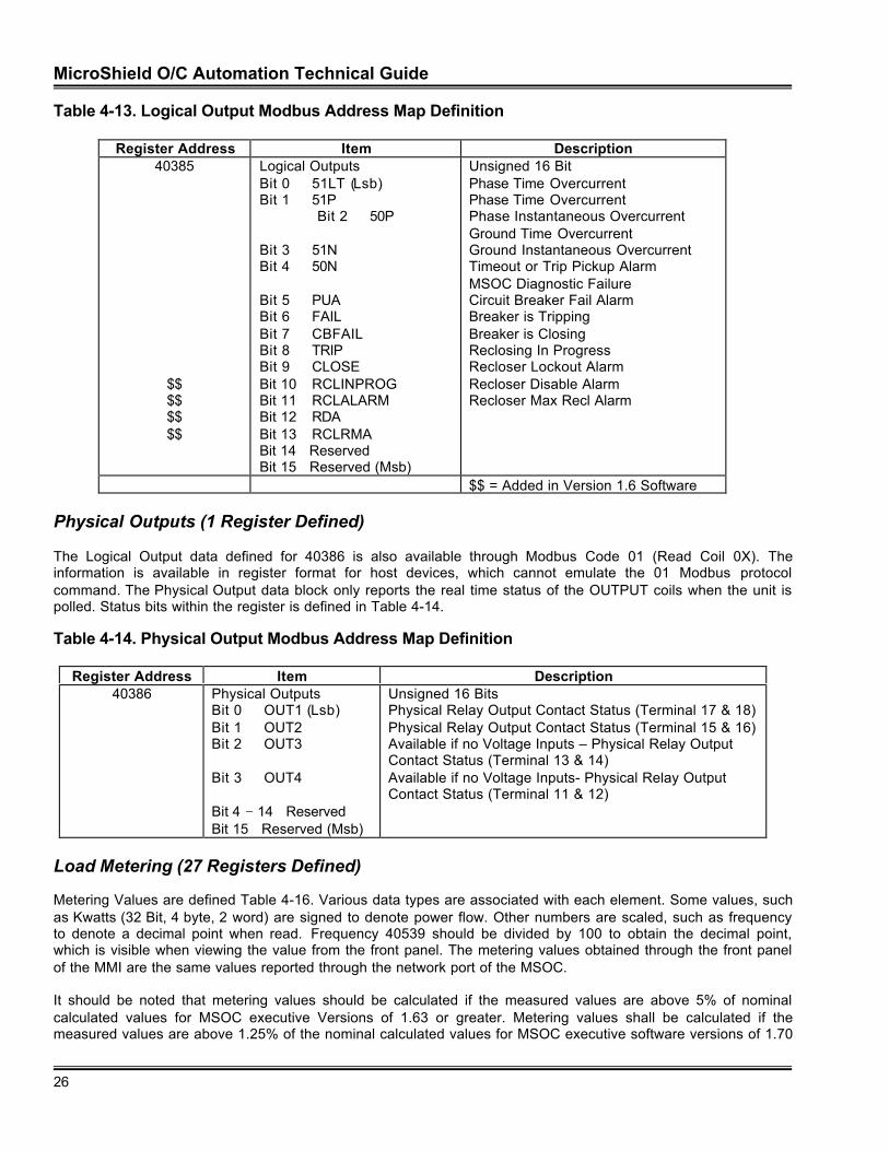
MicroShield O/C Automation Technical Guide
26
Table 4-13. Logical Output Modbus Address Map Definition
Register Address Item Description40385
$$$$$$$$
Logical OutputsBit 0 51LT (Lsb)Bit 1 51P
Bit 2 50P
Bit 3 51NBit 4 50N
Bit 5 PUABit 6 FAILBit 7 CBFAILBit 8 TRIPBit 9 CLOSEBit 10 RCLINPROGBit 11 RCLALARMBit 12 RDABit 13 RCLRMABit 14 ReservedBit 15 Reserved (Msb)
Unsigned 16 BitPhase Time OvercurrentPhase Time OvercurrentPhase Instantaneous OvercurrentGround Time OvercurrentGround Instantaneous OvercurrentTimeout or Trip Pickup AlarmMSOC Diagnostic FailureCircuit Breaker Fail AlarmBreaker is TrippingBreaker is ClosingReclosing In ProgressRecloser Lockout AlarmRecloser Disable AlarmRecloser Max Recl Alarm
$$ = Added in Version 1.6 Software
Physical Outputs (1 Register Defined)
The Logical Output data defined for 40386 is also available through Modbus Code 01 (Read Coil 0X). Theinformation is available in register format for host devices, which cannot emulate the 01 Modbus protocolcommand. The Physical Output data block only reports the real time status of the OUTPUT coils when the unit ispolled. Status bits within the register is defined in Table 4-14.
Table 4-14. Physical Output Modbus Address Map Definition
Register Address Item Description40386 Physical Outputs
Bit 0 OUT1 (Lsb)Bit 1 OUT2Bit 2 OUT3
Bit 3 OUT4
Bit 4 − 14 ReservedBit 15 Reserved (Msb)
Unsigned 16 BitsPhysical Relay Output Contact Status (Terminal 17 & 18)Physical Relay Output Contact Status (Terminal 15 & 16)Available if no Voltage Inputs – Physical Relay OutputContact Status (Terminal 13 & 14)Available if no Voltage Inputs- Physical Relay OutputContact Status (Terminal 11 & 12)
Load Metering (27 Registers Defined)
Metering Values are defined Table 4-16. Various data types are associated with each element. Some values, suchas Kwatts (32 Bit, 4 byte, 2 word) are signed to denote power flow. Other numbers are scaled, such as frequencyto denote a decimal point when read. Frequency 40539 should be divided by 100 to obtain the decimal point,which is visible when viewing the value from the front panel. The metering values obtained through the front panelof the MMI are the same values reported through the network port of the MSOC.
It should be noted that metering values should be calculated if the measured values are above 5% of nominalcalculated values for MSOC executive Versions of 1.63 or greater. Metering values shall be calculated if themeasured values are above 1.25% of the nominal calculated values for MSOC executive software versions of 1.70
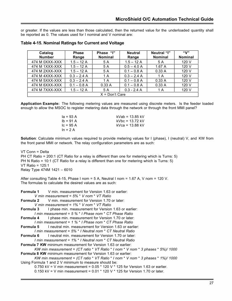
MicroShield O/C Automation Technical Guide
27
or greater. If the values are less than those calculated, then the returned value for the underloaded quantity shallbe reported as 0. The values used for I nominal and V nominal are:
Table 4-15. Nominal Ratings for Current and Voltage
CatalogNumber
PhaseRange
Phase “I”Nominal
NeutralRange
Neutral “I”Nominal
“V”Nominal
474 M 0XXX-XXX 1.5 – 12 A 5 A 1.5 – 12 A 5 A 120 V474 M 1XXX-XXX 1.5 – 12 A 5 A 0.5 – 4.0 A 1.67 A 120 V474 M 2XXX-XXX 1.5 – 12 A 5 A 0.1 – 0.8 A 0.33 A 120 V474 M 4XXX-XXX 0.3 – 2.4 A 1 A 0.3 – 2.4 A 1 A 120 V474 M 5XXX-XXX 0.3 – 2.4 A 1 A 0.1 – 0.8 A 0.33 A 120 V474 M 6XXX-XXX 0.1 – 0.8 A 0.33 A 0.1 – 0.8 A 0.33 A 120 V474 M 7XXX-XXX 1.5 – 12 A 5 A 0.3 - 2.4 A 1 A 120 V
X = Don’t Care
Application Example: The following metering values are measured using discrete meters. Is the feeder loadedenough to allow the MSOC to register metering data through the network or through the front MMI panel?
Ia = 93 A kVab = 13.85 kVIb = 91 A kVbc = 13.72 kVIc = 95 A kVca = 13.88 kVIn = 2 A
Solution: Calculate minimum values required to provide metering values for I (phase), I (neutral) V, and KW fromthe front panel MMI or network. The relay configuration parameters are as such:
VT Conn = DeltaPH CT Ratio = 200:1 (CT Ratio for a relay is different than one for metering which is Turns: 5)PH N Ratio = 10:1 (CT Ratio for a relay is different than one for metering which is Turns: 5)VT Ratio = 125:1Relay Type 474M 1421 – 6010
After consulting Table 4-15, Phase I nom = 5 A, Neutral I nom = 1.67 A, V nom = 120 V.The formulas to calculate the desired values are as such:
Formula 1 V min. measurement for Version 1.63 or earlier:V min measurement = 5% * V nom * VT Ratio
Formula 2 V min. measurement for Version 1.70 or later:V min measurement = 1% * V nom * VT Ratio
Formula 3 I phase min. measurement for Version 1.63 or earlier:I min measurement = 5 % * I Phase nom * CT Phase Ratio
Formula 4 I phase min. measurement for Version 1.70 or later:I min measurement = 1 % * I Phase nom * CT Phase Ratio
Formula 5 I neutral min. measurement for Version 1.63 or earlier:I min measurement = 5% * I Neutral nom * CT Neutral Ratio
Formula 6 I neutral min. measurement for Version 1.70 or later:I min measurement = 1% * I Neutral nom * CT Neutral Ratio
Formula 7 KW minimum measurement for Version 1.63 or earlier:KW min measurement = (CT ratio * VT Ratio * I nom * V nom * 3 phases * 5%)/ 1000
Formula 8 KW minimum measurement for Version 1.63 or earlier:KW min measurement = (CT ratio * VT Ratio * I nom * V nom * 3 phases * 1%)/ 1000
Using Formula 1 and 2 V minimum to measure should be:0.750 kV = V min measurement = 0.05 * 120 V * 125 for Version 1.63 or earlier.0.150 kV = V min measurement = 0.01 * 120 V * 125 for Version 1.70 or later.
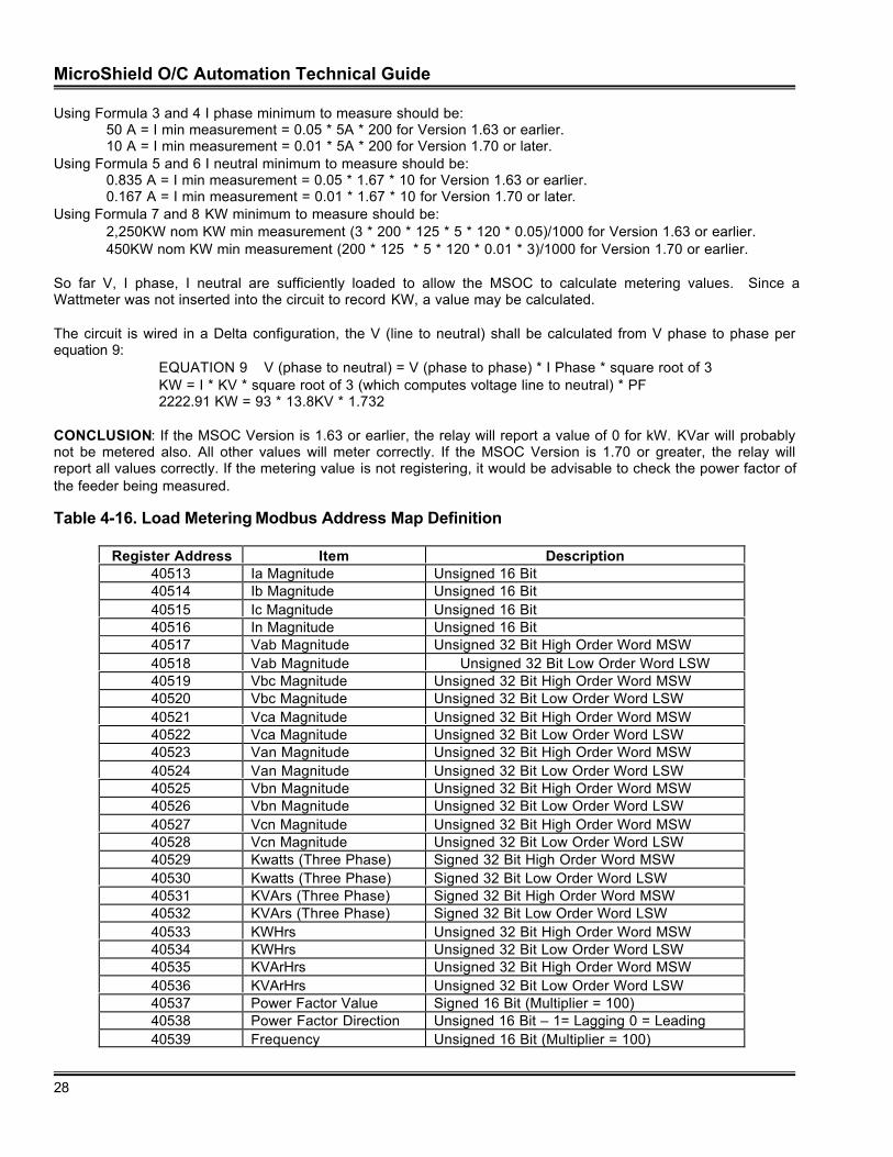
MicroShield O/C Automation Technical Guide
28
Using Formula 3 and 4 I phase minimum to measure should be:50 A = I min measurement = 0.05 * 5A * 200 for Version 1.63 or earlier.10 A = I min measurement = 0.01 * 5A * 200 for Version 1.70 or later.
Using Formula 5 and 6 I neutral minimum to measure should be:0.835 A = I min measurement = 0.05 * 1.67 * 10 for Version 1.63 or earlier.0.167 A = I min measurement = 0.01 * 1.67 * 10 for Version 1.70 or later.
Using Formula 7 and 8 KW minimum to measure should be:2,250KW nom KW min measurement (3 * 200 * 125 * 5 * 120 * 0.05)/1000 for Version 1.63 or earlier.450KW nom KW min measurement (200 * 125 * 5 * 120 * 0.01 * 3)/1000 for Version 1.70 or earlier.
So far V, I phase, I neutral are sufficiently loaded to allow the MSOC to calculate metering values. Since aWattmeter was not inserted into the circuit to record KW, a value may be calculated.
The circuit is wired in a Delta configuration, the V (line to neutral) shall be calculated from V phase to phase perequation 9:
EQUATION 9 V (phase to neutral) = V (phase to phase) * I Phase * square root of 3KW = I * KV * square root of 3 (which computes voltage line to neutral) * PF2222.91 KW = 93 * 13.8KV * 1.732
CONCLUSION: If the MSOC Version is 1.63 or earlier, the relay will report a value of 0 for kW. KVar will probablynot be metered also. All other values will meter correctly. If the MSOC Version is 1.70 or greater, the relay willreport all values correctly. If the metering value is not registering, it would be advisable to check the power factor ofthe feeder being measured.
Table 4-16. Load Metering Modbus Address Map Definition
Register Address Item Description40513 Ia Magnitude Unsigned 16 Bit40514 Ib Magnitude Unsigned 16 Bit40515 Ic Magnitude Unsigned 16 Bit40516 In Magnitude Unsigned 16 Bit40517 Vab Magnitude Unsigned 32 Bit High Order Word MSW40518 Vab Magnitude Unsigned 32 Bit Low Order Word LSW40519 Vbc Magnitude Unsigned 32 Bit High Order Word MSW40520 Vbc Magnitude Unsigned 32 Bit Low Order Word LSW40521 Vca Magnitude Unsigned 32 Bit High Order Word MSW40522 Vca Magnitude Unsigned 32 Bit Low Order Word LSW40523 Van Magnitude Unsigned 32 Bit High Order Word MSW40524 Van Magnitude Unsigned 32 Bit Low Order Word LSW40525 Vbn Magnitude Unsigned 32 Bit High Order Word MSW40526 Vbn Magnitude Unsigned 32 Bit Low Order Word LSW40527 Vcn Magnitude Unsigned 32 Bit High Order Word MSW40528 Vcn Magnitude Unsigned 32 Bit Low Order Word LSW40529 Kwatts (Three Phase) Signed 32 Bit High Order Word MSW40530 Kwatts (Three Phase) Signed 32 Bit Low Order Word LSW40531 KVArs (Three Phase) Signed 32 Bit High Order Word MSW40532 KVArs (Three Phase) Signed 32 Bit Low Order Word LSW40533 KWHrs Unsigned 32 Bit High Order Word MSW40534 KWHrs Unsigned 32 Bit Low Order Word LSW40535 KVArHrs Unsigned 32 Bit High Order Word MSW40536 KVArHrs Unsigned 32 Bit Low Order Word LSW40537 Power Factor Value Signed 16 Bit (Multiplier = 100)40538 Power Factor Direction Unsigned 16 Bit – 1= Lagging 0 = Leading40539 Frequency Unsigned 16 Bit (Multiplier = 100)
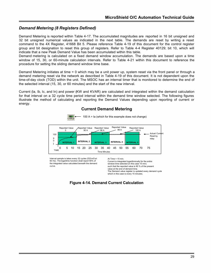
MicroShield O/C Automation Technical Guide
29
Demand Metering (8 Registers Defined)
Demand Metering is reported within Table 4-17. The accumulated magnitudes are reported in 16 bit unsigned and32 bit unsigned numerical values as indicated in the next table. The demands are reset by writing a resetcommand to the 4X Register, 41668 Bit 5. Please reference Table 4-19 of this document for the control registergroup and bit designation to reset this group of registers. Refer to Table 4-4 Register 40129; bit 10, which willindicate that a new Peak Demand Value has been accumulated within this table.Demand metering is calculated on a fixed demand window accumulation. The demands are based upon a timewindow of 15, 30, or 60-minute calculation intervals. Refer to Table 4-21 within this document to reference theprocedure for setting the sliding demand window time base.
Demand Metering initiates at time = 0 which may be a unit power up, system reset via the front panel or through ademand metering reset via the network as described in Table 4-19 of this document. It is not dependent upon thetime-of-day clock (TOD) within the unit. The MSOC has an internal timer that is monitored to determine the end ofthe selected interval (15, 30, or 60 minutes) and the start of the new interval.
Current (Ia, Ib, Ic, and In) and power (KW and KVAR) are calculated and integrated within the demand calculationfor that interval on a 32 cycle time period interval within the demand time window selected. The following figuresillustrate the method of calculating and reporting the Demand Values depending upon reporting of current orenergy.
Current Demand Metering
E
C
NetworkP a r t n e rV1.0 100 A = Ia (which for this example does not change)
Time Minutes
I0 5 10 15 20 25 30 35 40 45 50 55 60 70 75
90
At Time = 15 min.Current is integrated logarithmically for the entire window time selected (in this case 15 min)such that the reported value is 90 % of the presentvalue at the end of demand time.The Demand value register is updated every demand cyclewhich in this case is every 15 minutes.
100
INTERVAL 1
TIME
Actual CurrentRead by relay
INTERVAL 2 INTERVAL 3
Interval sample is taken every 32 cycles (533 mS at60 Hz). The logaritmic function shall report 90% of the integrated value calculated beneath the demand curve.
Reported Value 0
Reported Value 90 A
Reported Value 98 A
INTERVAL 4 INTERVAL 5
Reported Value 99 A
Reported Value 100 A
Figure 4-14. Demand Current Calculation
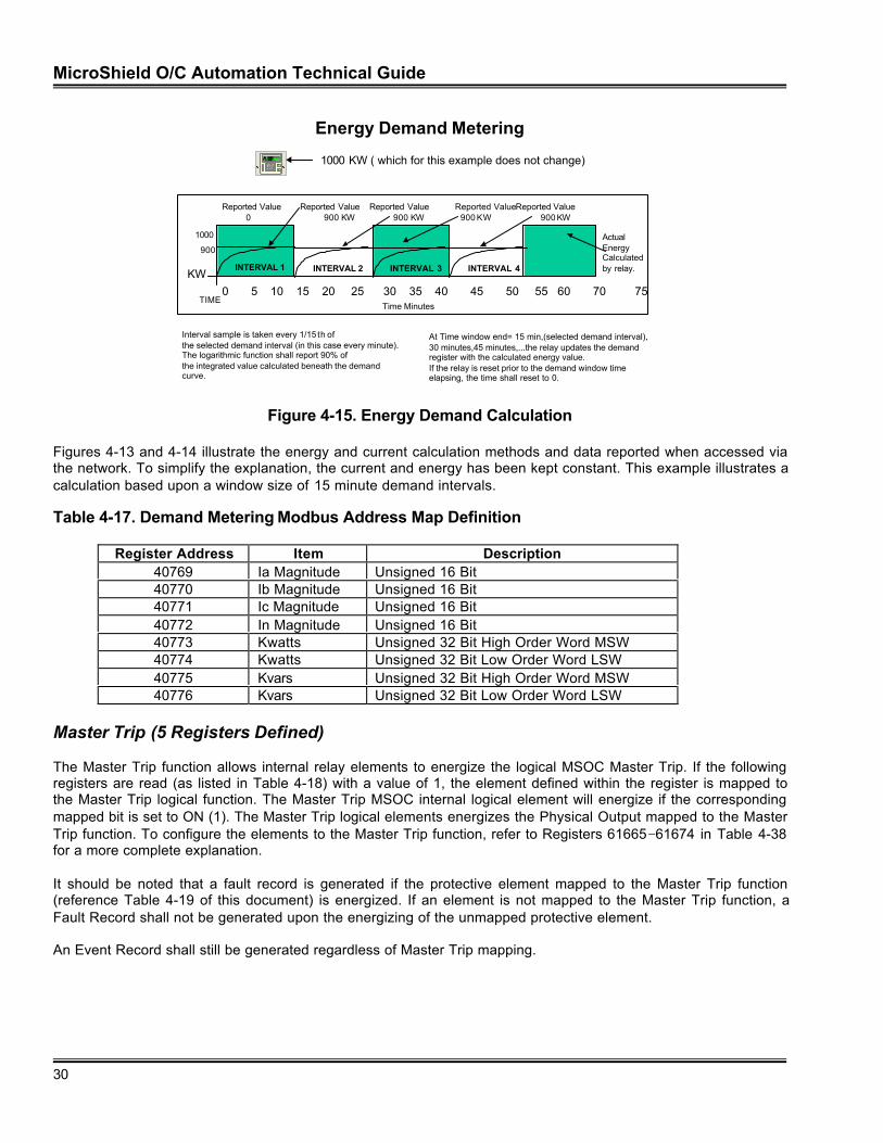
MicroShield O/C Automation Technical Guide
30
Energy Demand Metering
E
C
NetworkP a r t n e rV1.0 1000 KW ( which for this example does not change)
Time Minutes
KW0 5 10 15 20 25 30 35 40 45 50 55 60 70 75
At Time window end= 15 min,(selected demand interval),30 minutes,45 minutes,...the relay updates the demandregister with the calculated energy value.If the relay is reset prior to the demand window timeelapsing, the time shall reset to 0.
1000
TIME
ActualEnergyCalculated by relay.INTERVAL 1
Interval sample is taken every 1/15 th of the selected demand interval (in this case every minute).The logarithmic function shall report 90% of the integrated value calculated beneath the demand curve.
Reported Value 0
Reported Value 900 KW
Reported Value 900 KW
Reported Value 900 KW
Reported Value 900 KW
900
INTERVAL 2 INTERVAL 3 INTERVAL 4
Figure 4-15. Energy Demand Calculation
Figures 4-13 and 4-14 illustrate the energy and current calculation methods and data reported when accessed viathe network. To simplify the explanation, the current and energy has been kept constant. This example illustrates acalculation based upon a window size of 15 minute demand intervals.
Table 4-17. Demand Metering Modbus Address Map Definition
Register Address Item Description40769 Ia Magnitude Unsigned 16 Bit40770 Ib Magnitude Unsigned 16 Bit40771 Ic Magnitude Unsigned 16 Bit40772 In Magnitude Unsigned 16 Bit40773 Kwatts Unsigned 32 Bit High Order Word MSW40774 Kwatts Unsigned 32 Bit Low Order Word LSW40775 Kvars Unsigned 32 Bit High Order Word MSW40776 Kvars Unsigned 32 Bit Low Order Word LSW
Master Trip (5 Registers Defined)
The Master Trip function allows internal relay elements to energize the logical MSOC Master Trip. If the followingregisters are read (as listed in Table 4-18) with a value of 1, the element defined within the register is mapped tothe Master Trip logical function. The Master Trip MSOC internal logical element will energize if the correspondingmapped bit is set to ON (1). The Master Trip logical elements energizes the Physical Output mapped to the MasterTrip function. To configure the elements to the Master Trip function, refer to Registers 61665−61674 in Table 4-38for a more complete explanation.
It should be noted that a fault record is generated if the protective element mapped to the Master Trip function(reference Table 4-19 of this document) is energized. If an element is not mapped to the Master Trip function, aFault Record shall not be generated upon the energizing of the unmapped protective element.
An Event Record shall still be generated regardless of Master Trip mapping.
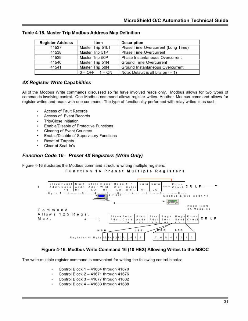
MicroShield O/C Automation Technical Guide
31
Table 4-18. Master Trip Modbus Address Map Definition
Register Address Item Description41537 Master Trip 51LT Phase Time Overcurrent (Long Time)41538 Master Trip 51P Phase Time Overcurrent41539 Master Trip 50P Phase Instantaneous Overcurrent41540 Master Trip 51N Ground Time Overcurrent41541 Master Trip 50N Ground Instantaneous Overcurrent
0 = OFF 1 = ON Note: Default is all bits on (= 1)
4X Register Write Capabilities
All of the Modbus Write commands discussed so far have involved reads only. Modbus allows for two types ofcommands involving control. One Modbus command allows register writes. Another Modbus command allows forregister writes and reads with one command. The type of functionality performed with relay writes is as such:
• Access of Fault Records• Access of Event Records• Trip/Close Initiation• Enable/Disable of Protective Functions• Clearing of Event Counters• Enable/Disable of Supervisory Functions• Reset of Targets• Clear of Seal In’s
Function Code 16 − Preset 4X Registers (Write Only)
Figure 4-16 illustrates the Modbus command structure writing multiple registers.
M o d b u s H o s t M o d b u s S l a v e A d d r = 1
R e a d f r o m 4 X M a p p i n g
S l a v eA d d r .
F u n c t .C o d e 1 0
S t a r tA d d rH I
S t a r t A d d r L O
R e g sW r i t H I
R e g sW r i t L O
# *B y t e sW r i t .
C R L F:
S l a v eA d d r .
F u n c t .C o d e 1 0
S t a r tA d d r H I
S t a r tA d d r L O
R e g sS e n t H I
R e g sS e n tL O
E r r o rC h e c k C R L F:
B y t e 1 … 2 … … . . 3 … … . 4 … … . 5 … … 6 … … . . 7 … . . . 8 … … … 9 … … … … X . . .
M S B L S B
1 5 1 4 1 3 1 2 1 1 1 0 9 8 7 6 5 4 3 2 1 0
M S B L S B
R e g i s t e r H i B y t e
D a t a
H I
D a t a
L O
E r r o rC h e c k
C o m m a n dA l l o w s 1 2 5 R e g s .M a x .
E
C
N e t w o r kP a r t n e r
V1.0
F u n c t i o n 1 6 P r e s e t M u l t i p l e R e g i s t e r s
Figure 4-16. Modbus Write Command 16 (10 HEX) Allowing Writes to the MSOC
The write multiple register command is convenient for writing the following control blocks:
• Control Block 1 – 41664 through 41670• Control Block 2 – 41671 through 41676• Control Block 3 – 41677 through 41682• Control Block 4 – 41683 through 41688
MicroShield O/C Automation Technical Guide
32
Control Block 1 allows for:
• Initiation of Relay Trip• Initiation of Relay Close• Resetting of Targets• Enabling or Disabling of Selective Protective Functions• Disabling or Enabling of Communication Port Functions• Enabling or Disabling of Supervisory Control Functions via the Communication Ports
Control Block 2 allows for:
• Forcing of Outputs 1 through 4 for a limited pulse duration time
Control Block 3 allows for:
• Reset of Latch Bit Functions
Control Block 4 allows for:
• Reserved Functions
Whenever a write occurs to the MSOC:
• The MSOC receives the command• Command Interpreted in 1 quarter cycle• Relay Protection Occurs• Command acts on the device• The command response is generated to the Host from the MSOC after the action is completed
The defined control blocks 1 and 2 are write capable and are well suited for access control via the Modbuscommand 16 (10 HEX).
Function 23 Read/Write Register (Read/Write Concurrently)
Another format command which allows for a simultaneous read/write is command 23 (17 Hex). Figure 4-17illustrates the Read/Write 4X Register command format. The 23 command is used when the user wishes to write aregister for control buffer access and read a group of registers which was accessed via the read.
Control Blocks 1 and 2 allows for access of protective device function state. If a user wished to read the status ofeach function within the relay, a Function Read/Write Register command would be the most desirable command tobe issued. Read/Write Register data commands are also useful in accessing the Operation and Fault recordblocks.
Review of the Modbus 23 command allows for write and read of data if the total amount of read and write registersdo not exceed over 125 words. An advantage of using a combined read/write command is that of speed. Ifconventional commands were to be used, a 16 Write 4X Register command would be issued and thereafter, within10 seconds, a 03 Modbus (Read 4X Register command) would then be issued to extract the data from the relay.Using Modbus command 23 allows for decreasing of the overhead associated with multiple register reads andwrites.
MicroShield O/C Automation Technical Guide
33
F u n c t i o n 2 3 R e a d / W r i t e 4 X R e g i s t e r s
M o d b u s H o s t
EC
M o d b u s S l a v e A d d r = 1
S l a v eA d d r.
F u n c t .C o d e 1 7
R e a dA d d rH I
R e a d A d d r L O
# R e g sR e a d H I
# R e g sR e a d L O
B y t e 1 … 2 … … . . 3 … … . 4 … … . 5 … … 6 … … . . 7 … . . . 8 … … … 9 … . . 1 0 … … 1 1 … … 1 2 … … … . . X
D a t a
H I
D a t a
L O
E r r o rC h e c k
C o m m a n dA l l o w s 1 2 5 R e g s .M a x .
W r i t eA d d r H I
W r i t eA d d r L O
# R e g sW r i t . H I
# R e g sW r i t . L O
B y t eC o u n t *
S l a v eA d d r .
F u n c t .C o d e 1 7
B y t eC o u n t *
D a t aB y t e H i
D a t aB y t e L o
D a t aB y t e L o
E r r o rC h e c k C R L F:
M S B L S B
1 5 1 4 1 3 1 2 1 1 1 0 9 8 7 6 5 4 3 2 1 0
M S B L S B
R e g i s t e r H i B y t e
:C RL F
Figure 4-17. Function 23 Read/Write Command Format
Fault Records (27 Registers Defined)
Fault records are stored in the MSOC according to the following format. Figure 4-18 illustrates the method ofaccessing the Fault Record Data via the MSOC. The MSOC has an internal circular buffer, which stores amaximum of 32 faults. These faults are stored internally to the MSOC’s fault stack as indicated in the figure. Eachfault is defined as a block of 26 registers as shown in Tables 4-19 and 4-20. The first defined register in the table isthe fault record control register. Fault records are viewed by writing a data word to 41025 as defined in the tablebelow and reading the block of consecutive Registers from 41026 through 41051.
If the number of faults exceed 32, then the buffer overwrites the oldest record contained within its internal stack.Access and control can be accomplished over Modbus in one of two methods.
If 41025 has a value of 1 written to it, Registers 41026 through 41051 will fill with the FIRST fault within the 32records stored in the unit. 41025 will then reset to a value of 0 when Registers 41046 through 41051 are read.
If 41025 has a value of 2 written to it, Registers 41026 through 41051 will contain the NEXT record of fault datawhich was pointed after the write command executed. 41025 will reset to a value of 0 after the record has enteredthe buffer and is read by the host.
If 41025 has a value of 3 written to it, Registers 41026 through 41051 will fill with the LAST record of fault data inthe 32 records of fault data stored in the unit. For example, if two records of data accumulated between reads, aread last record command would point to the last record of data accumulated in the buffer. The user would have tore-index the pointer to access the previous data fault record in the buffer. 41025 shall reset to a value of 0 afterthe record data is read.
If no data accumulated within the fault record, (such as after a system reset), values of 0 shall be returned in thebuffer. A new fault record entry is indicated via Bit 3 of Register 40129 being set to a 1. Reference Table 4-1 of thisdocument for a more detailed explanation of the registers bit map.
The Fault Record number can be a number from 1 to 999. Only the previous 32 records are kept in the fault recordbuffer. Fault Records are sequentially numbered from 1 to 999. If the fault number is presently at 999, and anadditional fault is recorded, the fault number shall rollover to 1. The Record number and fault buffer can be clearedand reset through a keypad reset procedure or a reset via the network as explained in Section 3 as a note. If theFault number retrieved is 0 then, no faults have been recorded by the relay. Front panel LCD access of the faultsshall indicate that no fault records are available.
METHOD 1:The host writes a Modbus 23 command (Modbus 4X Register Read/Write) in which a control code (1,2, or3) is written to 41025 and the buffer is filled with fault data in Registers 40126 through 41051 to bereturned as a response to the command. A command of 1 = Points to the First Record in the Fault Table.
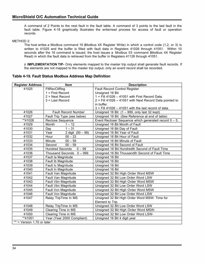
MicroShield O/C Automation Technical Guide
34
A command of 2 Points to the next fault in the fault table. A command of 3 points to the last fault in thefault table. Figure 4-18 graphically illustrates the write/read process for access of fault or operationrecords.
METHOD 2:The host writes a Modbus command 16 (Modbus 4X Register Write) in which a control code (1,2, or 3) iswritten to 41025 and the buffer is filled with fault data in Registers 41026 through 41051. Within 10seconds after the 16 command is issued, the host issues a Modbus 03 command (Modbus 4X RegisterRead) in which the fault data is retrieved from the buffer in Registers 41126 through 41051.
ÿ IMPLEMENTATION TIP- Only elements mapped to the master trip output shall generate fault records. Ifthe elements are not mapped to the master trip output, only an event record shall be recorded.
Table 4-19. Fault Status Modbus Address Map Definition
Register Address Item Description41025 FltRecCtlReg
1 = First Record2 = Next Record3 = Last Record
Fault Record Control RegisterUnsigned 16 Bit1 = Fill 41026 – 41051 with First Record Data.2 = Fill 41026 – 41051 with Next Record Data pointed toin buffer.3 = Fill 41026 – 41051 with the last record of data.
41026 Fault Record Number Unsigned 16 Bit (1 – 999, only last 32 kept)41027 Fault Trip Type (see below) Unsigned 16 Bit (See Reference at end of table)
**41028 Reclose Sequence Event Recloser Sequence which generated record 0 – 5.41029 Month 1 – 12 Unsigned 16 Bit Month of Fault41030 Day 1 – 31 Unsigned 16 Bit Day of Fault41031 Year 2 digit (00 – 99) Unsigned 16 Bit Year of Fault41032 Hour 00 – 23 Unsigned 16 Bit Hour of Fault41033 Minute 00 – 59 Unsigned 16 Bit Minute of Fault41034 Second 00 – 59 Unsigned 16 Bit Second of Fault41035 Hundred Seconds 0 – 99 Unsigned 16 Bit Hundredth Second of Fault Time41036 Thousand Seconds 0 – 999 Unsigned 16 Bit Thousandth Second of Fault Time41037 Fault Ia Magnitude Unsigned 16 Bit41038 Fault Ib Magnitude Unsigned 16 Bit41039 Fault Ic Magnitude Unsigned 16 Bit41040 Fault In Magnitude Unsigned 16 Bit41041 Fault Van Magnitude Unsigned 32 Bit High Order Word MSW41042 Fault Van Magnitude Unsigned 32 Bit Low Order Word LSW41043 Fault Vbn Magnitude Unsigned 32 Bit High Order Word MSW41044 Fault Vbn Magnitude Unsigned 32 Bit Low Order Word LSW41045 Fault Vcn Magnitude Unsigned 32 Bit High Order Word MSW41046 Fault Vcn Magnitude Unsigned 32 Bit Low Order Word LSW41047 Relay TripTime In MS Unsigned 32 Bit High Order Word MSW. Time for
Element to Trip.41048 Relay TripTime In MS Unsigned 32 Bit Low Order Word LSW41049 Clearing Time in MS Unsigned 32 Bit High Order Word MSW-41050 Clearing Time in MS Unsigned 32 Bit Low Order Word LSW-
**41051 Year (Year 2000 Compliant) Unsigned 16 Bit 4 digit year** = Version 1.70 or later
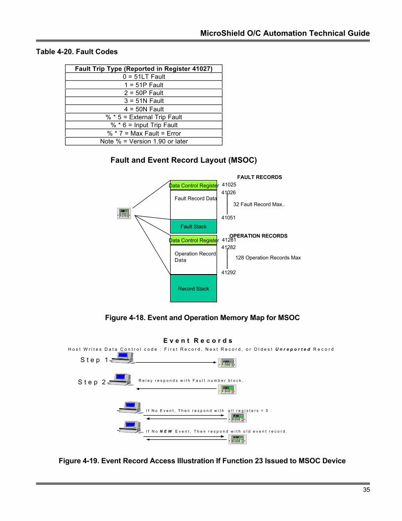
MicroShield O/C Automation Technical Guide
35
Table 4-20. Fault Codes
Fault Trip Type (Reported in Register 41027)0 = 51LT Fault1 = 51P Fault2 = 50P Fault3 = 51N Fault4 = 50N Fault
% * 5 = External Trip Fault% * 6 = Input Trip Fault
% * 7 = Max Fault = ErrorNote % = Version 1.90 or later
Fault and Event Record Layout (MSOC)
Data Control Register
Fault Record Data
4102541026
41051
FAULT RECORDS
Data Control Register
Operation RecordData
4128141282
41292
32 Fault Record Max..
128 Operation Records Max.
Fault Stack
Record Stack
E
C
NetworkPartnerV1.0
OPERATION RECORDS
Figure 4-18. Event and Operation Memory Map for MSOC
E v e n t R e c o r d s
S t e p 1 .
S t e p 2 .
H o s t W r i t e s D a t a C o n t r o l c o d e : F i r s t R e c o r d , N e x t R e c o r d , o r O l d e s t U n r e p o r t e d R e c o r d
R e l a y r e s p o n d s w i t h F a u l t n u m b e r b l o c k .
I f N o E v e n t , T h e n r e s p o n d w i t h a l l r e g i s t e r s = 0
I f N o N E W E v e n t , T h e n r e s p o n d w i t h o l d e v e n t r e c o r d .
E
C
N e t w o r k
P a r t n e rV 1 . 0
E
C
N e t w o r kP a r t n e r
V 1 . 0
E
C
Network
P a r t n e rV1.0
E
C
NetworkP a r t n e r
V1.0
Figure 4-19. Event Record Access Illustration If Function 23 Issued to MSOC Device
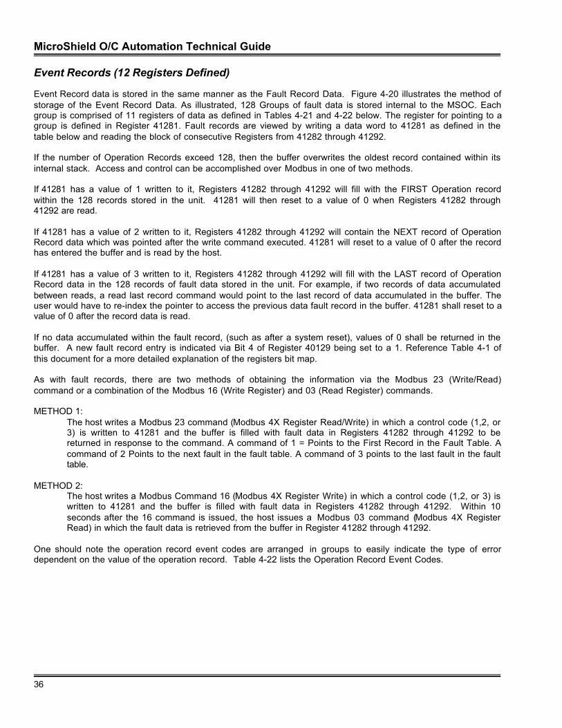
MicroShield O/C Automation Technical Guide
36
Event Records (12 Registers Defined)
Event Record data is stored in the same manner as the Fault Record Data. Figure 4-20 illustrates the method ofstorage of the Event Record Data. As illustrated, 128 Groups of fault data is stored internal to the MSOC. Eachgroup is comprised of 11 registers of data as defined in Tables 4-21 and 4-22 below. The register for pointing to agroup is defined in Register 41281. Fault records are viewed by writing a data word to 41281 as defined in thetable below and reading the block of consecutive Registers from 41282 through 41292.
If the number of Operation Records exceed 128, then the buffer overwrites the oldest record contained within itsinternal stack. Access and control can be accomplished over Modbus in one of two methods.
If 41281 has a value of 1 written to it, Registers 41282 through 41292 will fill with the FIRST Operation recordwithin the 128 records stored in the unit. 41281 will then reset to a value of 0 when Registers 41282 through41292 are read.
If 41281 has a value of 2 written to it, Registers 41282 through 41292 will contain the NEXT record of OperationRecord data which was pointed after the write command executed. 41281 will reset to a value of 0 after the recordhas entered the buffer and is read by the host.
If 41281 has a value of 3 written to it, Registers 41282 through 41292 will fill with the LAST record of OperationRecord data in the 128 records of fault data stored in the unit. For example, if two records of data accumulatedbetween reads, a read last record command would point to the last record of data accumulated in the buffer. Theuser would have to re-index the pointer to access the previous data fault record in the buffer. 41281 shall reset to avalue of 0 after the record data is read.
If no data accumulated within the fault record, (such as after a system reset), values of 0 shall be returned in thebuffer. A new fault record entry is indicated via Bit 4 of Register 40129 being set to a 1. Reference Table 4-1 ofthis document for a more detailed explanation of the registers bit map.
As with fault records, there are two methods of obtaining the information via the Modbus 23 (Write/Read)command or a combination of the Modbus 16 (Write Register) and 03 (Read Register) commands.
METHOD 1:The host writes a Modbus 23 command (Modbus 4X Register Read/Write) in which a control code (1,2, or3) is written to 41281 and the buffer is filled with fault data in Registers 41282 through 41292 to bereturned in response to the command. A command of 1 = Points to the First Record in the Fault Table. Acommand of 2 Points to the next fault in the fault table. A command of 3 points to the last fault in the faulttable.
METHOD 2:The host writes a Modbus Command 16 (Modbus 4X Register Write) in which a control code (1,2, or 3) iswritten to 41281 and the buffer is filled with fault data in Registers 41282 through 41292. Within 10seconds after the 16 command is issued, the host issues a Modbus 03 command (Modbus 4X RegisterRead) in which the fault data is retrieved from the buffer in Register 41282 through 41292.
One should note the operation record event codes are arranged in groups to easily indicate the type of errordependent on the value of the operation record. Table 4-22 lists the Operation Record Event Codes.
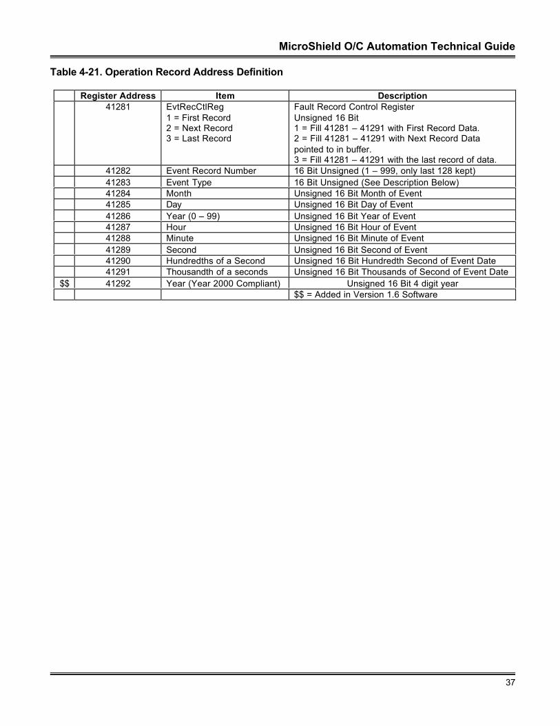
MicroShield O/C Automation Technical Guide
37
Table 4-21. Operation Record Address Definition
Register Address Item Description41281 EvtRecCtlReg
1 = First Record2 = Next Record3 = Last Record
Fault Record Control RegisterUnsigned 16 Bit1 = Fill 41281 – 41291 with First Record Data.2 = Fill 41281 – 41291 with Next Record Datapointed to in buffer.3 = Fill 41281 – 41291 with the last record of data.
41282 Event Record Number 16 Bit Unsigned (1 – 999, only last 128 kept)41283 Event Type 16 Bit Unsigned (See Description Below)41284 Month Unsigned 16 Bit Month of Event41285 Day Unsigned 16 Bit Day of Event41286 Year (0 – 99) Unsigned 16 Bit Year of Event41287 Hour Unsigned 16 Bit Hour of Event41288 Minute Unsigned 16 Bit Minute of Event41289 Second Unsigned 16 Bit Second of Event41290 Hundredths of a Second Unsigned 16 Bit Hundredth Second of Event Date41291 Thousandth of a seconds Unsigned 16 Bit Thousands of Second of Event Date
$$ 41292 Year (Year 2000 Compliant) Unsigned 16 Bit 4 digit year$$ = Added in Version 1.6 Software
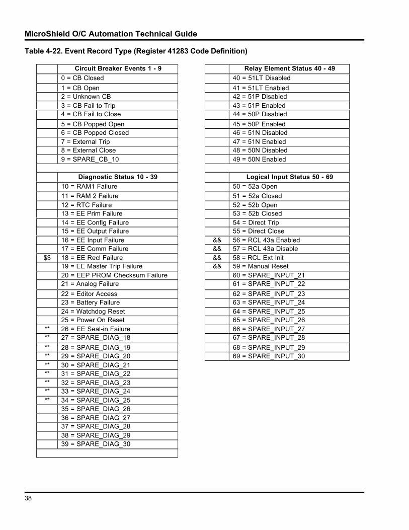
MicroShield O/C Automation Technical Guide
38
Table 4-22. Event Record Type (Register 41283 Code Definition)
Circuit Breaker Events 1 - 9 Relay Element Status 40 - 490 = CB Closed 40 = 51LT Disabled
1 = CB Open 41 = 51LT Enabled2 = Unknown CB 42 = 51P Disabled3 = CB Fail to Trip 43 = 51P Enabled4 = CB Fail to Close 44 = 50P Disabled
5 = CB Popped Open 45 = 50P Enabled6 = CB Popped Closed 46 = 51N Disabled7 = External Trip 47 = 51N Enabled8 = External Close 48 = 50N Disabled9 = SPARE_CB_10 49 = 50N Enabled
Diagnostic Status 10 - 39 Logical Input Status 50 - 6910 = RAM1 Failure 50 = 52a Open11 = RAM 2 Failure 51 = 52a Closed12 = RTC Failure 52 = 52b Open13 = EE Prim Failure 53 = 52b Closed14 = EE Config Failure 54 = Direct Trip15 = EE Output Failure 55 = Direct Close16 = EE Input Failure && 56 = RCL 43a Enabled17 = EE Comm Failure && 57 = RCL 43a Disable
$$ 18 = EE Recl Failure && 58 = RCL Ext Init19 = EE Master Trip Failure && 59 = Manual Reset20 = EEP PROM Checksum Failure 60 = SPARE_INPUT_2121 = Analog Failure 61 = SPARE_INPUT_22
22 = Editor Access 62 = SPARE_INPUT_2323 = Battery Failure 63 = SPARE_INPUT_2424 = Watchdog Reset 64 = SPARE_INPUT_2525 = Power On Reset 65 = SPARE_INPUT_26
** 26 = EE Seal-in Failure 66 = SPARE_INPUT_27** 27 = SPARE_DIAG_18 67 = SPARE_INPUT_28
** 28 = SPARE_DIAG_19 68 = SPARE_INPUT_29** 29 = SPARE_DIAG_20 69 = SPARE_INPUT_30** 30 = SPARE_DIAG_21** 31 = SPARE_DIAG_22** 32 = SPARE_DIAG_23** 33 = SPARE_DIAG_24** 34 = SPARE_DIAG_25
35 = SPARE_DIAG_2636 = SPARE_DIAG_2737 = SPARE_DIAG_2838 = SPARE_DIAG_2939 = SPARE_DIAG_30
MicroShield O/C Automation Technical Guide
39
Logical Output Events 70 - 99 Operations Events 110 - 11970 = 51LT Trip 110 = Reset Energy Meters71 = 51LT Pickup 111 = Clear Record72 = 51LT Dropout ** 112 = Reset Seal-Ins73 = 51P Trip 113 = SPARE_OPS_474 = 51P Pickup 114 = SPARE_OPS_575 = 51P Dropout 115 = SPARE_OPS_676 = 50P Trip 116 = SPARE_OPS_777 = 50P Pickup 117 = SPARE_OPS_878 = 50P Dropout 118 = SPARE_OPS_9
79 = 51N Trip 119 = SPARE_OPS_1080 = 51N Pickup81 = 51N Dropout Recloser Events 120 - 13982 = 50N Trip ** 120 = Recloser 43a Enabled
83 = 50N Pickup ** 121 = Recloser 43a Disabled84 = 50N Dropout ** 122 = Recloser Enabled
85 = Clear 51LT Event ** 123 = Recloser Disabled86 = Clear 51P Event ** 124 = Recloser in Progress87 = Clear 50P Event ** 125 = External Recloser Initiated88 = Clear 51N Event ** 126 = Recloser Lockout89 = Clear 50N Event ** 127 = Recloser Reset90 = Reset 51LT Event ** 128 = Recloser Out Of Sequence91 = Reset 51P Event ** 129 = Max Recover Exceeded92 = Reset 50P Event ** 130 = Recloser Recover93 = Reset 51N Event ** 131 = Max Recloses Exceeded94 = Reset 50N Event ** 132 = Max Recloser Resets
&& 95 = Recloser Enabled ** 133 = Zone Step&& 96 = Recloser Disabled ** 134 = Recloser Error
97 = SPARE_OUTPUT_28 ** 135 = Recloser Initiated98 = SPARE_OUTPUT_29 ** 136 = SPARE_RECL_1799 = SPARE_OUTPUT_30 ** 137 = SPARE_RECL_18
** 138 = SPARE_RECL_19Internal MSOC Events 100 - 109 ** 139 = SPARE_RECL_20
100 = QSI Initialization failure101= Com Init MSG Failure Internal Errors Events 140 - 141102 = APC Param Update 140 = Illegal Event Code103 = Int Tx Failure 141 = Event Code Error104 = Wrong (Modbus) Block Rec’d105 = NW Param update
106= Int Rx Failure107 = SPARE_COMM_08
$$ = Added in Version 1.6 Software** = Added in Version 1.7 Software&& = Added in Version 1.8 Software
108 = SPARE_COMM_09109 = SPARE_COMM_10
MicroShield O/C Automation Technical Guide
40
Mask Control Block (27 Registers Defined)
As described in the beginning of this section, four groups of control blocks are resident in the MSOC. Each groupis comprised of 6 registers. The four control blocks defined in Table 25 require a password to control thefunctionality within the unit.
The method to perform control through the Mask Control Block is as follows:
• Write all registers other than the register associated with the “Execute Register”
• Write a “1” or “2” to execute the command or refresh the registers with the control command.
Groups I, II, III and IV share commonality in that an operation type must be written to the Execute Register(Register 41665 in Group I, 41671 in Group II, 41677 in Group III, and 41683 in Group IV). Also a Password mustbe written to the block for the desired function to execute. The registers allow for refresh and update. Figure 24illustrates graphically the difference between the two terms. In the MSOC, all write terms are transferred to abuffer and written to the relay. In an update buffer scenario, the contents are transferred from the buffer andburned into the MSOC’s internal flash RAM for retention. The memory is also updated automatically. In a refresh,the contents of memory are taken from the MSOC’s internal memory and transferred to the unit’s visible memoryarea. Thus the memory seen by the operator is “ refreshed” with the latest data.
E
C
NetworkPartnerV1.0
Memory Visible
to the Operator
Memory Retentive
Flash RAM invisible tothe operator
E
C
NetworkPartnerV1.0
Memory Visible
to the Operator
Memory Retentive
Flash RAM invisible tothe operator
Refresh Registers
Update Registers
Figure 4-20. Update and Refresh Functionality
Group 1 allows for control and access of Trip and Close functionality (through bits 0 and 1 of register 41669 and41670) within the relay. The length of trip is three cycles and length of the close is six cycles. Bit 2 resets allactive targets within the relay. The function’s execution can be visually seen as the LED’s on the front panel of theunit extinguish upon a fault. Bits 3, 4 and 5, enable or disable the functionality of the internal protective functions.Bit 6 clears all records, Fault and Operational within the relay. Bit 7 is important in that all SCADA type controlfunctions can be disabled via the network. If the functions are disabled, then all control is via the front panelinterface or via “Torque Control” performed via the input terminals on the relay. The front RS 232 communicationinterface may be enabled or disabled from operation via a write. Remember, only one port on the MSOC may beactive at any one time.
The unit password is set via the front panel interface of the MSOC. The default password for the unit is all spaces.The HEX code for all spaces is 20 20. Thus if the MSOC has the default password within the unit, registers 41666and 41667 must send the HEX equivalent of the ASCII code via Modbus. The register data would be 41666 =2020 41667 = 2020 ( for Group I access for example).
MicroShield O/C Automation Technical Guide
41
If a user wished to perform a check before operate control sequence for Group I, the control could be performed inthree separate write operations, Registers 41666 through 41669 written first, Register 41670 written second.Registers 41666 through 40670 checked for validity via a Modbus Read (Code 03). Finally, a Modbus Write to41665 to initiate control would initiate control. A Check Before Operate was a common method of control beforeprotocol checksums were the norm. Such sequences, although through the use of modern protocols areunnecessary, can still be duplicated over Modbus. The registers will retain their values for an indefinite timeperiod. Only the execute register resets to a value of 0 for a control sequence.
The method for performing Group I functions is shown in Figures 4-21 through 4-23. Each control bit defined inRegisters 41669 and 41670 has a specific task for function enable, function disable and function performance.Table 4-23 Illustrates the control bit combinations for each task.
Table 4-23. Group 1 Control Function Bit Combinations
Register 41669 Register 41670 DescriptionBit 0 = 1 Bit 0 = 1 Trip Breaker (Rightmost Bit)Bit 1 = 1 Bit 1 = 1 Close BreakerBit 2 = 1 Bit 2 = 1 Reset TargetsBit 3 = 1Bit 3 = 1
Bit 3 = 1Bit 3 = 0
Disable 79 (Recloser Trip Function Disabled)Enable 79 (Recloser Trip Function Enabled)
Bit 4 = 1Bit 4 = 1
Bit 4 = 1Bit 4 = 0
Disable Ground (Ground Fault Function Disabled)Enable Ground (Ground Fault Function Enabled)
Bit 5 = 1 Bit 5 = 1 Reset Energy MetersBit 6 = 1 Bit 6 = 1 Clear Fault and Event BuffersBit 7 = 1Bit 7 = 1
Bit 7 = 1Bit 7 = 0
Disable Supervisory (Supervisory Network Control Disabled)Enable Supervisory (Supervisory Network Control Enabled)
Bit 8 = 1Bit 8 = 1
Bit 8 = 1Bit 8 = 0
Disable Front RS 232 Port (Rear RS 485 Port Enabled)Enable Front RS 232 Port (Rear RS 485 Port Disabled)
Bit 9 = 1 Bit 9 = 1 Reset Seal-In Points
Group II, allows for control of the Physical Outputs at the back of the relay. Control initiation occurs using anexecute command, password and two registers (41675 and 41676). Figure 4-22 illustrates the control of theoutput using a specific sequence. Table 4-24 illustrates the configuration of the Change Register State register(41675) and the Force Register State register (41676).
Table 4-24. Configuration of Change Register State and Force Register State
Register 41675 Register 41676 DescriptionBit X = 1 Bit X = 1 Pulse the selected output to a state of 1 for ½ second.
Group III allows for reset of each individual latched bits within the MSOC.
Group IV is reserved.
Table 4-25. Write Group Functionality
Register Address Item DescriptionGROUP I
41664 RESERVED41665 Execute Register
0 = No Action1 = Update Registers2 = Refresh Registers
Unsigned 16 Bit
41666 Password ASCII – 2 Characters (Leftmost Digits)41667 Password ASCII – 2 Characters (Rightmost Digits)41668 Spare
MicroShield O/C Automation Technical Guide
42
**
41669 Change RegisterBit 0 Initiate CB Trip (Lsb)Bit 1 Initiate CB CloseBit 2 Reset TargetsBit 3 Disable 79Bit 4 Disable GroundBit 5 RESET Energy MetersBit 6 Clear RecordsBit 7 Disable SupervisorBit 8 Enable Front PortBit 9 Reset Seal InsBit 10 − Bit14 ReservedBit15 Reserved (Msb)
16 Bit Unsigned RegisterForce Circuit Breaker TripForce Circuit Breaker CloseReset Targets in Relay and Front PanelRecloser Trip Function DisabledDisable Ground Fault FunctionReset Energy Meter.Clear Fault And Event Record BuffersDisable Network Supervisory ControlEnable RS 232 Port Disable RS 485 Port1= Enable Network Reset of Seal Ins
41670 Confirmation Register Contents of this register are ANDED with Register 41669to perform control functionality. If Registers 41670 and41669 are not equal control will not occur.
GROUP II41671 Execute Register
0 = No Action1 = Update Registers2 = Refresh Registers
16 Bit Unsigned
41672 Password ASCII – 2 Characters (Leftmost Digits)41673 Password ASCII – 2 Characters (Rightmost Digits)41674 Spare41675 Change Register
Bit 0 Output 1Bit 1 Output 2Bit 2 Output 3
Bit 3 Output 4
Bit 4 − 14 ReservedBit15 Reserved
Unsigned 16 BitPhysical Relay Output Contact Status (Terminal 17 & 18)Physical Relay Output Contact Status (Terminal 15 & 16)Available if no Voltage Inputs – Physical Relay OutputContact Status (Terminal 13 & 14)Available if no Voltage Inputs – Physical Relay OutputContact Status (Terminal 11 & 12)
41676 Confirmation Register Contents of this register are ANDED with Register 41675to perform control functionality. If Registers 41675 and41676 are not equal control will not occur.
GROUP III
** 41677 Execute Register0 = No Action1 = Update Registers2 = Refresh Registers
16 Bit Unsigned
** 41678 Password ASCII – 2 Characters (Leftmost Digits)** 41679 Password ASCII – 2 Characters (Rightmost Digits)** 41680 Spare** 41681 Reset Register#1 (for Seal-Ins)
Bit 0 51LT*Bit 1 51P*Bit 2 50P*Bit 3 51N*Bit 4 50N*Bit 5 PUA*Bit 6 FAIL*Bit 7 CBFAIL*Bit 8 TRIP*
Unsigned 16 Bits- Latched Data ControlPhase Time OvercurrentPhase Time OvercurrentPhase Instantaneous OvercurrentGround Time OvercurrentGround Instantaneous OvercurrentTimeout or Trip Pickup AlarmMSOC Diagnostic FailureCircuit Breaker Fail AlarmBreaker is Tripping
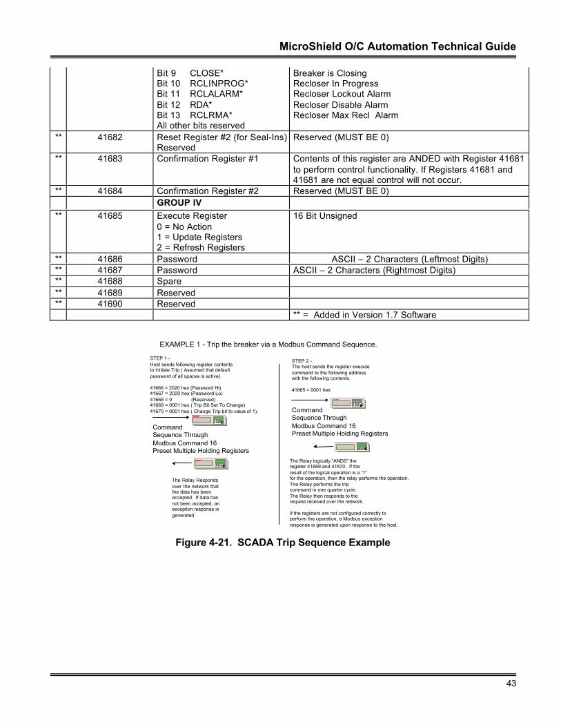
MicroShield O/C Automation Technical Guide
43
Bit 9 CLOSE*Bit 10 RCLINPROG*Bit 11 RCLALARM*Bit 12 RDA*Bit 13 RCLRMA*All other bits reserved
Breaker is ClosingRecloser In ProgressRecloser Lockout AlarmRecloser Disable AlarmRecloser Max Recl Alarm
** 41682 Reset Register #2 (for Seal-Ins)Reserved
Reserved (MUST BE 0)
** 41683 Confirmation Register #1 Contents of this register are ANDED with Register 41681to perform control functionality. If Registers 41681 and41681 are not equal control will not occur.
** 41684 Confirmation Register #2 Reserved (MUST BE 0)GROUP IV
** 41685 Execute Register0 = No Action1 = Update Registers2 = Refresh Registers
16 Bit Unsigned
** 41686 Password ASCII – 2 Characters (Leftmost Digits)** 41687 Password ASCII – 2 Characters (Rightmost Digits)** 41688 Spare** 41689 Reserved** 41690 Reserved
** = Added in Version 1.7 Software
EC
CommandSequence ThroughModbus Command 16Preset Multiple Holding Registers
STEP 1 -Host sends following register contentsto initiate Trip ( Assumed that defaultpassword of all spaces is active).
41666 = 2020 hex (Password Hi)41667 = 2020 hex (Password Lo)41668 = 0 (Reserved)41669 = 0001 hex ( Trip Bit Set To Change)41670 = 0001 hex ( Change Trip bit to value of 1).
EXAMPLE 1 - Trip the breaker via a Modbus Command Sequence.
EC
The Relay logically “ANDS” the register 41669 and 41670. If the result of the logical operation is a “1”for the operation, then the relay performs the operation.The Relay performs the tripcommand in one quarter cycle.The Relay then responds to therequest received over the network.
If the registers are not configured correctly toperform the operation, a Modbus exception response is generated upon response to the host.
EC
CommandSequence ThroughModbus Command 16Preset Multiple Holding Registers
STEP 2 -The host sends the register executecommand to the following address with the following contents.
41665 = 0001 hex
EC
The Relay Respondsover the network that the data has been accepted. If data has not been accepted, anexception response isgenerated
Figure 4-21. SCADA Trip Sequence Example
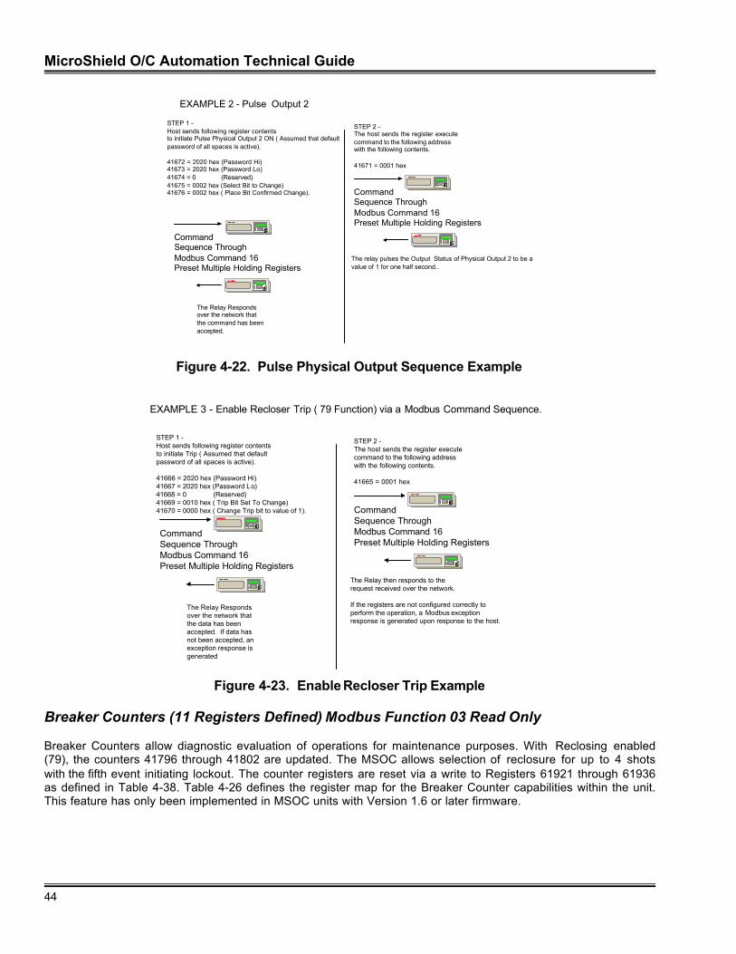
MicroShield O/C Automation Technical Guide
44
EC
CommandSequence ThroughModbus Command 16Preset Multiple Holding Registers
STEP 1 -Host sends following register contentsto initiate Pulse Physical Output 2 ON ( Assumed that defaultpassword of all spaces is active).
41672 = 2020 hex (Password Hi)41673 = 2020 hex (Password Lo)41674 = 0 (Reserved)41675 = 0002 hex (Select Bit to Change)41676 = 0002 hex ( Place Bit Confirmed Change).
EXAMPLE 2 - Pulse Output 2
EC
The relay pulses the Output Status of Physical Output 2 to be a value of 1 for one half second..
EC
CommandSequence ThroughModbus Command 16Preset Multiple Holding Registers
STEP 2 -The host sends the register executecommand to the following address with the following contents.
41671 = 0001 hex
EC
The Relay Respondsover the network that the command has been accepted.
Figure 4-22. Pulse Physical Output Sequence Example
EC
CommandSequence ThroughModbus Command 16Preset Multiple Holding Registers
STEP 1 -Host sends following register contentsto initiate Trip ( Assumed that defaultpassword of all spaces is active).
41666 = 2020 hex (Password Hi)41667 = 2020 hex (Password Lo)41668 = 0 (Reserved)41669 = 0010 hex ( Trip Bit Set To Change)41670 = 0000 hex ( Change Trip bit to value of 1).
EXAMPLE 3 - Enable Recloser Trip ( 79 Function) via a Modbus Command Sequence.
EC
The Relay then responds to therequest received over the network.
If the registers are not configured correctly toperform the operation, a Modbus exception response is generated upon response to the host.
EC
CommandSequence ThroughModbus Command 16Preset Multiple Holding Registers
STEP 2 -The host sends the register executecommand to the following address with the following contents.
41665 = 0001 hex
EC
The Relay Respondsover the network that the data has been accepted. If data has not been accepted, anexception response isgenerated
Figure 4-23. Enable Recloser Trip Example
Breaker Counters (11 Registers Defined) Modbus Function 03 Read Only
Breaker Counters allow diagnostic evaluation of operations for maintenance purposes. With Reclosing enabled(79), the counters 41796 through 41802 are updated. The MSOC allows selection of reclosure for up to 4 shotswith the fifth event initiating lockout. The counter registers are reset via a write to Registers 61921 through 61936as defined in Table 4-38. Table 4-26 defines the register map for the Breaker Counter capabilities within the unit.This feature has only been implemented in MSOC units with Version 1.6 or later firmware.
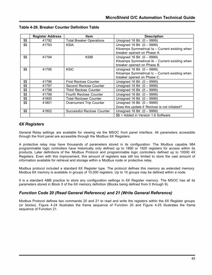
MicroShield O/C Automation Technical Guide
45
Table 4-26. Breaker Counter Definition Table
Register Address Item Description$$ 41792 Total Breaker Operations Unsigned 16 Bit (0 – 9999)$$ 41793 KSIA Unsigned 16 Bit (0 – 9999)
Kiloamps Symmetrical Ia – Current existing whenbreaker opened on Phase A.
$$ 41794 KSIB Unsigned 16 Bit (0 – 9999)Kiloamps Symmetrical Ib – Current existing whenbreaker opened on Phase B.
$$ 41795 KSIC Unsigned 16 Bit (0 – 9999)Kiloamps Symmetrical Ic – Current existing whenbreaker opened on Phase C.
$$ 41796 First Reclose Counter Unsigned 16 Bit (0 – 9999)$$ 41797 Second Reclose Counter Unsigned 16 Bit (0 – 9999)$$ 41798 Third Reclose Counter Unsigned 16 Bit (0 – 9999)$$ 41799 Fourth Reclose Counter Unsigned 16 Bit (0 – 9999)$$ 41800 Total Recloser Counter Unsigned 16 Bit (0 – 9999)$$ 41801 Overcurrent Trip Counter Unsigned 16 Bit (0 – 9999)
Does this update if Reclose is not initiated?$$ 41802 Successful Reclose Counter Unsigned 16 Bit (0 – 9999)
$$ = Added in Version 1.6 Software
6X Registers
General Relay settings are available for viewing via the MSOC front panel interface. All parameters accessiblethrough the front panel are accessible through the Modbus 6X Registers.
A protective relay may have thousands of parameters stored in its configuration. The Modbus capable 984programmable logic controllers have historically only defined up to 1890 or 1920 registers for access within itsproducts. Later definitions of the Modbus Protocol and programmable logic controllers defined up to 10000 4XRegisters. Even with this improvement, this amount of registers was still too limited to store the vast amount ofinformation available for retrieval and storage within a Modbus node or protective relay.
Modbus protocol included a standard 6X Register type. The protocol defines this memory as extended memory.Modbus 6X memory is available in groups of 10,000 registers. Up to 10 groups may be defined within a node.
It is a standard ABB practice to store any configuration settings in 6X Register memory. The MSOC has all itsparameters stored in Block 0 of the 6X memory definition (Blocks being defined from 0 through 9).
Function Code 20 (Read General Reference) and 21 (Write General Reference)
Modbus Protocol defines two commands 20 and 21 to read and write the registers within the 6X Register groups(or blocks). Figure 4-24 illustrates the frame sequence of Function 20 and Figure 4-25 illustrates the framesequence of Function 21.
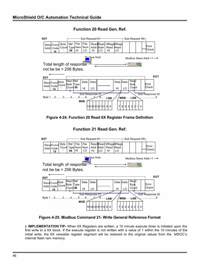
MicroShield O/C Automation Technical Guide
46
Function 20 Read Gen. Ref.
Modbus Host
SlaveAddr.
Funct.Code 14
ErrorCheck
ReadAddr HI
ReadAddr LO
#RegsRead HI
#RegsRead LO
ByteCount *
RefType 06
FileNumHI
FileNum LO
Sub Request 01 Sub Request XX
EC
Modbus Slave Addr =1
SOT
SlaveAddr.
Funct.Code 14
Data
LO
Data
HI
Byte 1 …2……..3…….4…….5……6……..7…. 8……...………………………………………..…..X
Data
HI
Data
LO
ErrorCheck
ByteCount *
Req1ByteCount %
RefType 06
Sub Response 01 Sub Response 02
SOT EOT
Total length of responsenot be be > 256 Bytes.
Req2ByteCount %
MSBLSB
151413121110 9 8 7 6 5 4 3 2 1 0
MSB LSB
Figure 4-24. Function 20 Read 6X Register Frame Definition
Function 21 Read Gen. Ref.
Modbus Host
SlaveAddr.
Funct.Code 15
ErrorCheck
ReadAddr HI
ReadAddr LO
#RegsRead HI
#RegsRead LO
ByteCount *
RefType 06
FileNumHI
FileNum LO
Sub Request 01 Sub Request XX
EC
Modbus Slave Addr =1
SOT
SlaveAddr.
Funct.Code 15
Data
LO
Data
HI
Byte 1 …2……..3…….4…….5……6……..7…. 8……...………………………………………..…..X
Data
HI
Data
LO
ErrorCheck
ByteCount *
Req1ByteCount %
RefType 06
Sub Response 01 Sub Response 02
SOT EOT
Total length of responsenot be be > 256 Bytes.
Req2ByteCount %
MSBLSB
151413121110 9 8 7 6 5 4 3 2 1 0
MSB LSB
Figure 4-25. Modbus Command 21- Write General Reference Format
ÿ IMPLEMENTATION TIP- When 6X Registers are written, a 10 minute execute timer is initiated upon thefirst write to a 6X block. If the execute register is not written with a value of 1 within the 10 minutes of theinitial write, the 6X viewable register segment will be restored to the original values from the MSOC’sinternal flash ram memory.
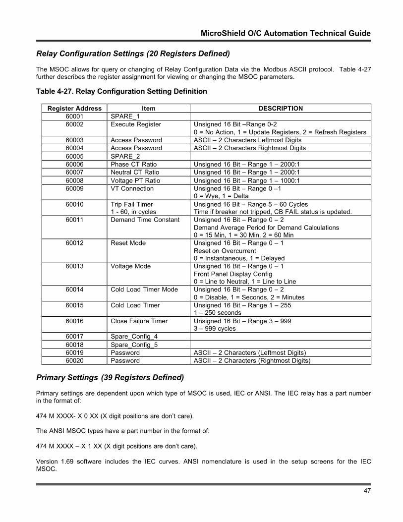
MicroShield O/C Automation Technical Guide
47
Relay Configuration Settings (20 Registers Defined)
The MSOC allows for query or changing of Relay Configuration Data via the Modbus ASCII protocol. Table 4-27further describes the register assignment for viewing or changing the MSOC parameters.
Table 4-27. Relay Configuration Setting Definition
Register Address Item DESCRIPTION60001 SPARE_160002 Execute Register Unsigned 16 Bit –Range 0-2
0 = No Action, 1 = Update Registers, 2 = Refresh Registers60003 Access Password ASCII – 2 Characters Leftmost Digits60004 Access Password ASCII – 2 Characters Rightmost Digits60005 SPARE_260006 Phase CT Ratio Unsigned 16 Bit – Range 1 – 2000:160007 Neutral CT Ratio Unsigned 16 Bit – Range 1 – 2000:160008 Voltage PT Ratio Unsigned 16 Bit – Range 1 – 1000:160009 VT Connection Unsigned 16 Bit – Range 0 –1
0 = Wye, 1 = Delta60010 Trip Fail Timer
1 - 60, in cyclesUnsigned 16 Bit – Range 5 – 60 CyclesTime if breaker not tripped, CB FAIL status is updated.
60011 Demand Time Constant Unsigned 16 Bit – Range 0 – 2Demand Average Period for Demand Calculations0 = 15 Min, 1 = 30 Min, 2 = 60 Min
60012 Reset Mode Unsigned 16 Bit – Range 0 – 1Reset on Overcurrent0 = Instantaneous, 1 = Delayed
60013 Voltage Mode Unsigned 16 Bit – Range 0 – 1Front Panel Display Config0 = Line to Neutral, 1 = Line to Line
60014 Cold Load Timer Mode Unsigned 16 Bit – Range 0 – 20 = Disable, 1 = Seconds, 2 = Minutes
60015 Cold Load Timer Unsigned 16 Bit – Range 1 – 2551 – 250 seconds
60016 Close Failure Timer Unsigned 16 Bit – Range 3 – 9993 – 999 cycles
60017 Spare_Config_460018 Spare_Config_560019 Password ASCII – 2 Characters (Leftmost Digits)60020 Password ASCII – 2 Characters (Rightmost Digits)
Primary Settings (39 Registers Defined)
Primary settings are dependent upon which type of MSOC is used, IEC or ANSI. The IEC relay has a part numberin the format of:
474 M XXXX- X 0 XX (X digit positions are don’t care).
The ANSI MSOC types have a part number in the format of:
474 M XXXX – X 1 XX (X digit positions are don’t care).
Version 1.69 software includes the IEC curves. ANSI nomenclature is used in the setup screens for the IECMSOC.
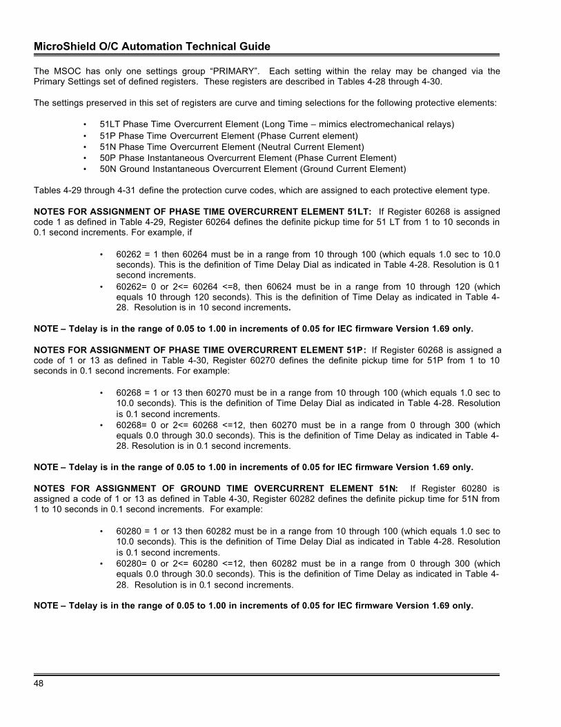
MicroShield O/C Automation Technical Guide
48
The MSOC has only one settings group “PRIMARY”. Each setting within the relay may be changed via thePrimary Settings set of defined registers. These registers are described in Tables 4-28 through 4-30.
The settings preserved in this set of registers are curve and timing selections for the following protective elements:
• 51LT Phase Time Overcurrent Element (Long Time – mimics electromechanical relays)• 51P Phase Time Overcurrent Element (Phase Current element)• 51N Phase Time Overcurrent Element (Neutral Current Element)• 50P Phase Instantaneous Overcurrent Element (Phase Current Element)• 50N Ground Instantaneous Overcurrent Element (Ground Current Element)
Tables 4-29 through 4-31 define the protection curve codes, which are assigned to each protective element type.
NOTES FOR ASSIGNMENT OF PHASE TIME OVERCURRENT ELEMENT 51LT: If Register 60268 is assignedcode 1 as defined in Table 4-29, Register 60264 defines the definite pickup time for 51 LT from 1 to 10 seconds in0.1 second increments. For example, if
• 60262 = 1 then 60264 must be in a range from 10 through 100 (which equals 1.0 sec to 10.0seconds). This is the definition of Time Delay Dial as indicated in Table 4-28. Resolution is 0.1second increments.
• 60262= 0 or 2<= 60264 <=8, then 60624 must be in a range from 10 through 120 (whichequals 10 through 120 seconds). This is the definition of Time Delay as indicated in Table 4-28. Resolution is in 10 second increments.
NOTE – Tdelay is in the range of 0.05 to 1.00 in increments of 0.05 for IEC firmware Version 1.69 only.
NOTES FOR ASSIGNMENT OF PHASE TIME OVERCURRENT ELEMENT 51P: If Register 60268 is assigned acode of 1 or 13 as defined in Table 4-30, Register 60270 defines the definite pickup time for 51P from 1 to 10seconds in 0.1 second increments. For example:
• 60268 = 1 or 13 then 60270 must be in a range from 10 through 100 (which equals 1.0 sec to10.0 seconds). This is the definition of Time Delay Dial as indicated in Table 4-28. Resolutionis 0.1 second increments.
• 60268= 0 or 2<= 60268 <=12, then 60270 must be in a range from 0 through 300 (whichequals 0.0 through 30.0 seconds). This is the definition of Time Delay as indicated in Table 4-28. Resolution is in 0.1 second increments.
NOTE – Tdelay is in the range of 0.05 to 1.00 in increments of 0.05 for IEC firmware Version 1.69 only.
NOTES FOR ASSIGNMENT OF GROUND TIME OVERCURRENT ELEMENT 51N: If Register 60280 isassigned a code of 1 or 13 as defined in Table 4-30, Register 60282 defines the definite pickup time for 51N from1 to 10 seconds in 0.1 second increments. For example:
• 60280 = 1 or 13 then 60282 must be in a range from 10 through 100 (which equals 1.0 sec to10.0 seconds). This is the definition of Time Delay Dial as indicated in Table 4-28. Resolutionis 0.1 second increments.
• 60280= 0 or 2<= 60280 <=12, then 60282 must be in a range from 0 through 300 (whichequals 0.0 through 30.0 seconds). This is the definition of Time Delay as indicated in Table 4-28. Resolution is in 0.1 second increments.
NOTE – Tdelay is in the range of 0.05 to 1.00 in increments of 0.05 for IEC firmware Version 1.69 only.
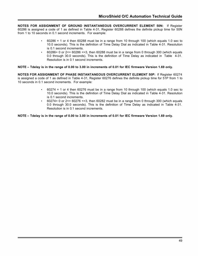
MicroShield O/C Automation Technical Guide
49
NOTES FOR ASSIGNMENT OF GROUND INSTANTANEOUS OVERCURRENT ELEMENT 50N: If Register60286 is assigned a code of 1 as defined in Table 4-31, Register 60288 defines the definite pickup time for 50Nfrom 1 to 10 seconds in 0.1 second increments. For example:
• 60286 = 1 or 4 then 60288 must be in a range from 10 through 100 (which equals 1.0 sec to10.0 seconds). This is the definition of Time Delay Dial as indicated in Table 4-31. Resolutionis 0.1 second increments.
• 60286= 0 or 2<= 60286 <=3, then 60288 must be in a range from 0 through 300 (which equals0.0 through 30.0 seconds). This is the definition of Time Delay as indicated in Table 4-31.Resolution is in 0.1 second increments.
NOTE – Tdelay is in the range of 0.00 to 3.00 in increments of 0.01 for IEC firmware Version 1.69 only.
NOTES FOR ASSIGNMENT OF PHASE INSTANTANEOUS OVERCURRENT ELEMENT 50P: If Register 60274is assigned a code of 1 as defined in Table 4-31, Register 60276 defines the definite pickup time for 51P from 1 to10 seconds in 0.1 second increments. For example:
• 60274 = 1 or 4 then 60276 must be in a range from 10 through 100 (which equals 1.0 sec to10.0 seconds). This is the definition of Time Delay Dial as indicated in Table 4-31. Resolutionis 0.1 second increments.
• 60274= 0 or 2<= 60276 <=3, then 60282 must be in a range from 0 through 300 (which equals0.0 through 30.0 seconds). This is the definition of Time Delay as indicated in Table 4-31.Resolution is in 0.1 second increments.
NOTE – Tdelay is in the range of 0.00 to 3.00 in increments of 0.01 for IEC firmware Version 1.69 only.
MicroShield O/C Automation Technical Guide
50
Table 4-28. Primary Settings Register Definition
Register Address Item Description60257 SPARE_160258 Execute Register Unsigned 16 Bits
0 = No Action, 1 = Update Registers, 2 = Refresh Registers60259 Access Password ASCII – 2 Characters (Leftmost Digits)60260 Access Password ASCII – 2 Characters (Rightmost Digits)60261 SPARE_260262 51LTCurve (Type I) Unsigned 16 Bits − Range 0 – 8 (See Table 4-23)60263 51LTPickupAmps Unsigned 16 Bits − Range 30 – 240
Divide by 100 for front panel value.60264 51LTTimeDelayDial Unsigned 16 Bits
10 – 100 / 10 – 120. SEE NOTES PRECEEDING TABLE60265 SPARE1_51LT Spare60266 SPARE2_51LT Spare60267 SPARE3_51LT60268 51PCurve (Type II) Unsigned 16 Bits − Range 0 – 8 (See Table 4-23)60269 51PPickupAmps Unsigned 16 Bits − Range 30 – 240.
30 – 240. Divide by 100 for front panel value.60270 51PTimeDelayDial Unsigned 16 Bits
10 – 100 / 0 – 300. SEE NOTES PRECEEDING TABLE60271 SPARE1_51P60272 SPARE2_51P60273 SPARE3_51P60274 50PCurve (Type III) Unsigned 16 Bits − Range 0 – 4 (See Table 4-24)60275 50PPickupXAmps Unsigned 16 Bits − Range 1– 200
10 – 200. Divide by 10 for front panel value.60276 50PTimeDelayDial Unsigned 16 Bits
10 – 100 / 0 – 300. SEE NOTES PRECEEDING TABLE60277 SPARE1_50P60278 SPARE2_50P60279 SPARE3_50P60280 51NCurve (Type II) Unsigned 16 Bits − Range 0 –13 (See Table 4-23)60281 51NPickupAmps Unsigned 16 Bits − Range 30 – 240
30 – 240. Divide by 100 for value.60282 51NTimeDelayDial Unsigned 16 Bits
10 – 100 / 0 – 300. SEE NOTES PRECEEDING TABLE60283 SPARE1_51N60284 SPARE2_51N60285 SPARE3_51N60286 50NCurve (Type III) Unsigned 16 Bits − Range 0 – 4 (See Table 4-25)60287 50NPickupXAmps Unsigned 16 Bits − Range 0 – 200
0 – 200. Divide by 10 for value. Multiply * 51 N for pickup setting.60288 50NTimeDelayDial Unsigned 16 Bits
10 – 100 / 0 – 300. SEE NOTES PRECEEDING TABLE60289 SPARE1_50N60290 SPARE2_50N60291 SPARE3_50N60292 SPARE_PRIM160293 SPARE_PRIM260294 SPARE_PRIM360295 SPARE_PRIM4
MicroShield O/C Automation Technical Guide
51
Table 4-29. Curve Selection Definition for 51LT (Register 60262)
Curve Selection Type I (51LT)0 = Disable1 = Definite2 = Long Time Extremely Inverse3 = Long Time Very Inverse4 = Long Time Inverse5 = Very Long Time Ext. Inverse6 = Very Long Time Very Inverse7 = Very Long Time Inverse
** 8 = IEC – Long Time Inverse** = Added in Version 1.7 Software
Table 4-30. Curve Selection Definition for 51N and 51P (Registers 60274 and 60287)
Curve Selection Type II (51 Curves)0 = Disable 1 = Definite2 = Long Time Extremely Inverse3 = Long Time Very Inverse4 = Long Time Inverse5 = Extremely Inverse6 = Very Inverse7 = Inverse8 = Short Time Inverse
** 9 = IEC – Extremely Inverse** 10 = IEC – Very Inverse** 11 = IEC – Inverse** 12 = IEC – Long Time Inverse** 13 = Definite Time #2
** = Added in Version 1.7 Software
Table 4-31. Curve Selection Definition for 50N and 50P (Registers 60274 and 60287)
Curve Selection Type III (50 Curves)0 = Disable1 = Definite2 = Standard3 = Short Time Inverse
** 4 = Definite Time #2** = Added in Version 1.7 Software
Aux Communication Settings (22 Registers Defined)
This set of defined registers allows for monitoring or changing the communication port parameters assigned to aspecific port. An operator should be aware that changing these ports will immediately effect the internal MSOCcommunication hardware and cause a communication error. The host’s communication port should bereconfigured to reflect the changes made to the unit’s port parameters. Only one port may be enabled at any time.Table 4-32 lists and defines the memory mapping for Modbus.
Register 60786 is the TX_DLY time. This is a unique register in that the MSOC can respond to a Modbus requestrapidly (within 3 mS). Some hosts may not see such a rapid response in that the hardware is unable to process
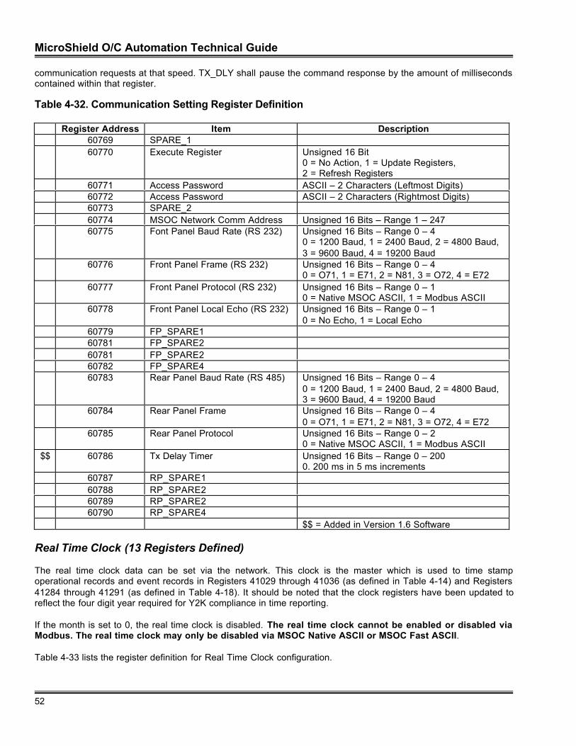
MicroShield O/C Automation Technical Guide
52
communication requests at that speed. TX_DLY shall pause the command response by the amount of millisecondscontained within that register.
Table 4-32. Communication Setting Register Definition
Register Address Item Description60769 SPARE_160770 Execute Register Unsigned 16 Bit
0 = No Action, 1 = Update Registers,2 = Refresh Registers
60771 Access Password ASCII – 2 Characters (Leftmost Digits)60772 Access Password ASCII – 2 Characters (Rightmost Digits)60773 SPARE_260774 MSOC Network Comm Address Unsigned 16 Bits – Range 1 – 24760775 Font Panel Baud Rate (RS 232) Unsigned 16 Bits – Range 0 – 4
0 = 1200 Baud, 1 = 2400 Baud, 2 = 4800 Baud,3 = 9600 Baud, 4 = 19200 Baud
60776 Front Panel Frame (RS 232) Unsigned 16 Bits – Range 0 – 40 = O71, 1 = E71, 2 = N81, 3 = O72, 4 = E72
60777 Front Panel Protocol (RS 232) Unsigned 16 Bits – Range 0 – 10 = Native MSOC ASCII, 1 = Modbus ASCII
60778 Front Panel Local Echo (RS 232) Unsigned 16 Bits – Range 0 – 10 = No Echo, 1 = Local Echo
60779 FP_SPARE160781 FP_SPARE260781 FP_SPARE260782 FP_SPARE460783 Rear Panel Baud Rate (RS 485) Unsigned 16 Bits – Range 0 – 4
0 = 1200 Baud, 1 = 2400 Baud, 2 = 4800 Baud,3 = 9600 Baud, 4 = 19200 Baud
60784 Rear Panel Frame Unsigned 16 Bits – Range 0 – 40 = O71, 1 = E71, 2 = N81, 3 = O72, 4 = E72
60785 Rear Panel Protocol Unsigned 16 Bits – Range 0 – 20 = Native MSOC ASCII, 1 = Modbus ASCII
$$ 60786 Tx Delay Timer Unsigned 16 Bits – Range 0 – 2000. 200 ms in 5 ms increments
60787 RP_SPARE160788 RP_SPARE260789 RP_SPARE260790 RP_SPARE4
$$ = Added in Version 1.6 Software
Real Time Clock (13 Registers Defined)
The real time clock data can be set via the network. This clock is the master which is used to time stampoperational records and event records in Registers 41029 through 41036 (as defined in Table 4-14) and Registers41284 through 41291 (as defined in Table 4-18). It should be noted that the clock registers have been updated toreflect the four digit year required for Y2K compliance in time reporting.
If the month is set to 0, the real time clock is disabled. The real time clock cannot be enabled or disabled viaModbus. The real time clock may only be disabled via MSOC Native ASCII or MSOC Fast ASCII.
Table 4-33 lists the register definition for Real Time Clock configuration.
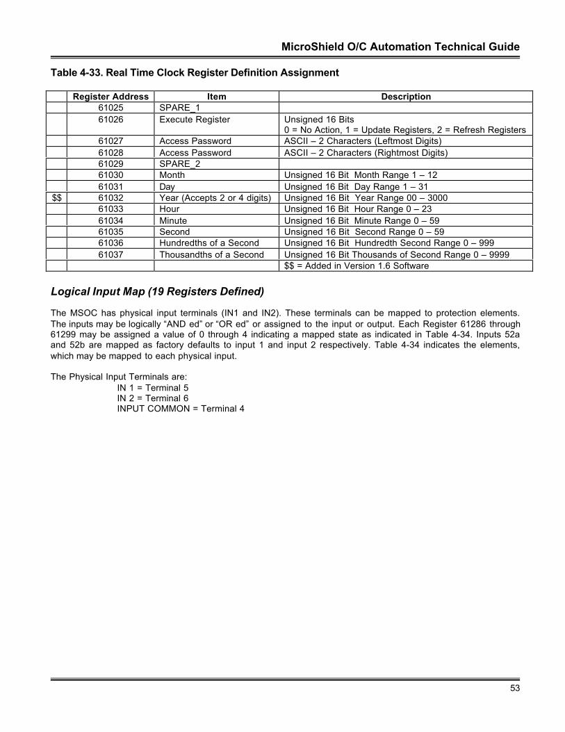
MicroShield O/C Automation Technical Guide
53
Table 4-33. Real Time Clock Register Definition Assignment
Register Address Item Description61025 SPARE_161026 Execute Register Unsigned 16 Bits
0 = No Action, 1 = Update Registers, 2 = Refresh Registers61027 Access Password ASCII – 2 Characters (Leftmost Digits)61028 Access Password ASCII – 2 Characters (Rightmost Digits)61029 SPARE_261030 Month Unsigned 16 Bit Month Range 1 – 1261031 Day Unsigned 16 Bit Day Range 1 – 31
$$ 61032 Year (Accepts 2 or 4 digits) Unsigned 16 Bit Year Range 00 – 300061033 Hour Unsigned 16 Bit Hour Range 0 – 2361034 Minute Unsigned 16 Bit Minute Range 0 – 5961035 Second Unsigned 16 Bit Second Range 0 – 5961036 Hundredths of a Second Unsigned 16 Bit Hundredth Second Range 0 – 99961037 Thousandths of a Second Unsigned 16 Bit Thousands of Second Range 0 – 9999
$$ = Added in Version 1.6 Software
Logical Input Map (19 Registers Defined)
The MSOC has physical input terminals (IN1 and IN2). These terminals can be mapped to protection elements.The inputs may be logically “AND ed” or “OR ed” or assigned to the input or output. Each Register 61286 through61299 may be assigned a value of 0 through 4 indicating a mapped state as indicated in Table 4-34. Inputs 52aand 52b are mapped as factory defaults to input 1 and input 2 respectively. Table 4-34 indicates the elements,which may be mapped to each physical input.
The Physical Input Terminals are: IN 1 = Terminal 5
IN 2 = Terminal 6INPUT COMMON = Terminal 4
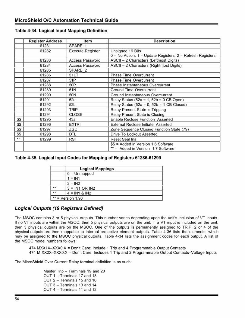
MicroShield O/C Automation Technical Guide
54
Table 4-34. Logical Input Mapping Definition
Register Address Item Description61281 SPARE_161282 Execute Register Unsigned 16 Bits
0 = No Action, 1 = Update Registers, 2 = Refresh Registers61283 Access Password ASCII – 2 Characters (Leftmost Digits)61284 Access Password ASCII – 2 Characters (Rightmost Digits)61285 SPARE_261286 51LT Phase Time Overcurrent61287 51P Phase Time Overcurrent61288 50P Phase Instantaneous Overcurrent61289 51N Ground Time Overcurrent61290 50N Ground Instantaneous Overcurrent61291 52a Relay Status (52a = 1, 52b = 0 CB Open)61292 52b Relay Status (52a = 0, 52b = 1 CB Closed)61293 TRIP Relay Present State is Tripping61294 CLOSE Relay Present State is Closing
$$ 61295 43a Enable Reclose Function Asserted$$ 61296 EXTRI External Reclose Initiate Asserted$$ 61297 ZSC Zone Sequence Closing Function State (79)$$ 61298 DTL Drive To Lockout Asserted** 61299 RSI Reset Seal Ins
$$ = Added in Version 1.6 Software** = Added in Version 1.7 Software
Table 4-35. Logical Input Codes for Mapping of Registers 61286-61299
Logical Mappings0 = Unmapped1 = IN12 = IN2
** 3 = IN1 OR IN2** 4 = IN1 & IN2** = Version 1.90
Logical Outputs (19 Registers Defined)
The MSOC contains 3 or 5 physical outputs. This number varies depending upon the unit’s inclusion of VT inputs.If no VT inputs are within the MSOC, then 5 physical outputs are on the unit. If a VT input is included on the unit,then 3 physical outputs are on the MSOC. One of the outputs is permanently assigned to TRIP, 2 or 4 of thephysical outputs are then mappable to internal protective element outputs. Table 4-36 lists the elements, whichmay be assigned to the MSOC physical outputs. Table 4-34 lists the assignment codes for each output. A list ofthe MSOC model numbers follows:
474 MXX1X–XXX0:X = Don’t Care: Include 1 Trip and 4 Programmable Output Contacts474 M XX2X–XXX0:X = Don’t Care: Includes 1 Trip and 2 Programmable Output Contacts–Voltage Inputs
The MicroShield Over Current Relay terminal definition is as such:
Master Trip – Terminals 19 and 20OUT 1 – Terminals 17 and 18OUT 2 – Terminals 15 and 16OUT 3 – Terminals 13 and 14OUT 4 – Terminals 11 and 12
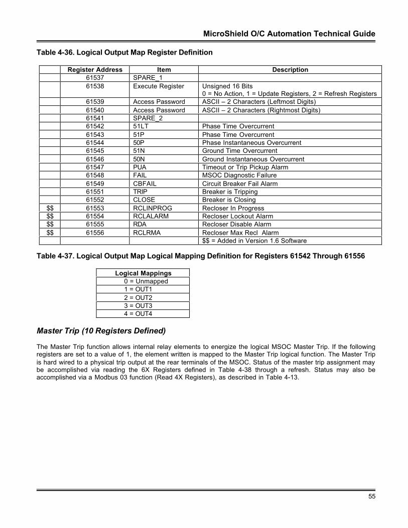
MicroShield O/C Automation Technical Guide
55
Table 4-36. Logical Output Map Register Definition
Register Address Item Description61537 SPARE_161538 Execute Register Unsigned 16 Bits
0 = No Action, 1 = Update Registers, 2 = Refresh Registers61539 Access Password ASCII – 2 Characters (Leftmost Digits)61540 Access Password ASCII – 2 Characters (Rightmost Digits)61541 SPARE_261542 51LT Phase Time Overcurrent61543 51P Phase Time Overcurrent61544 50P Phase Instantaneous Overcurrent61545 51N Ground Time Overcurrent61546 50N Ground Instantaneous Overcurrent61547 PUA Timeout or Trip Pickup Alarm61548 FAIL MSOC Diagnostic Failure61549 CBFAIL Circuit Breaker Fail Alarm61551 TRIP Breaker is Tripping61552 CLOSE Breaker is Closing
$$ 61553 RCLINPROG Recloser In Progress$$ 61554 RCLALARM Recloser Lockout Alarm$$ 61555 RDA Recloser Disable Alarm$$ 61556 RCLRMA Recloser Max Recl Alarm
$$ = Added in Version 1.6 Software
Table 4-37. Logical Output Map Logical Mapping Definition for Registers 61542 Through 61556
Logical Mappings0 = Unmapped1 = OUT12 = OUT23 = OUT34 = OUT4
Master Trip (10 Registers Defined)
The Master Trip function allows internal relay elements to energize the logical MSOC Master Trip. If the followingregisters are set to a value of 1, the element written is mapped to the Master Trip logical function. The Master Tripis hard wired to a physical trip output at the rear terminals of the MSOC. Status of the master trip assignment maybe accomplished via reading the 6X Registers defined in Table 4-38 through a refresh. Status may also beaccomplished via a Modbus 03 function (Read 4X Registers), as described in Table 4-13.
MicroShield O/C Automation Technical Guide
56
Table 4-38. Master Trip Assignment Definition Table
Register Address Item Description61665 SPARE_161666 Execute Register Unsigned 16 Bits
0 = No Action, 1 = Update Registers, 2 = Refresh Registers61667 Access Password ASCII – 2 Characters (Leftmost Digits)61668 Access Password ASCII – 2 Characters (Rightmost Digits)61669 SPARE_261670 Master 51LT Phase Time Overcurrent (Long Time)61671 Master 51P Phase Time Overcurrent61672 Master 50P Phase Instantaneous Overcurrent61673 Master 51N Ground Time Overcurrent61674 Master 50N Ground Instantaneous Overcurrent
0 = OFF 1 = ON
Recloser Settings (69 Registers Defined)
MSOC recloser capabilities were introduced in Version 1.60 software. Table 4-39 lists the register definitions foreach of the Recloser parameters. The ABB implementation allows for multiple shots of reclosing. EXTRI inputmust be mapped to a Physical Input.
Also the 52a and or 52b contact must be mapped to an input contact for reclosing to function. Time overcurrentand instantaneous overcurrent (50 and 51) functions may be enabled, disabled or assigned “Lock Out” status asillustrated in the table.
Table 4-39. Recloser Assignment Definition Table
Register Address Item Description$$ 61793 SPARE_1$$ 61794 Execute Register Unsigned 16 Bits
0 = No Action, 1 = Update Registers,2 = Refresh Registers
$$ 61795 Access Password ASCII – 2 Characters (Leftmost Digits)$$ 61796 Access Password ASCII – 2 Characters (Rightmost Digits)$$ 61797 SPARE_2$$ 61798 Recloser R1 Open Time Unsigned 16 Bits – Range 1 − 2000
0.1 − 200, Lockout. Divide by 10 to obtainfront panel value in seconds. (79-1)
$$ 61799 Recloser R1 50P Select Unsigned 16 BitPhase Instantaneous Overcurrent Phase0 = Enable, 1 = Disable 2 = Lockout
$$ 61800 Recloser R1 50N Select Unsigned 16 BitPhase Instantaneous Overcurrent Neutral0 = Enable, 1 = Disable, 2 = Lockout
$$ 61801 Recloser R1 51N Select Unsigned 16 BitPhase Time Overcurrent Neutral0 = Enable, 1 = Disable, 2 = Lockout
$$ 61802 Recloser R1 51LT Select Unsigned 16 BitPhase Time Overcurrent Long Time0 = Enable, 1 = Disable, 2 = Lockout
$$ 61803 Recloser R1 51P Lockout Unsigned 16 BitPhase Time Overcurrent Phase0 = Enable, 1 = Disable, 2 = Lockout
MicroShield O/C Automation Technical Guide
57
$$ 61804 Recloser R1 SPARE1$$ 61805 Recloser R1 SPARE2$$ 61806 Recloser R1 SPARE3$$ 61807 Recloser R1 SPARE4$$ 61808 Recloser R1 SPARE5$$ 61809 Recloser R2 Open Time Unsigned 16 Bits – Range 1 − 2000
0.1 − 200, Lockout. Divide by 10 to obtainfront panel value in seconds. (79-2)
$$ 61810 Recloser R2 50P Select Unsigned 16 BitPhase Instantaneous Overcurrent Phase0 = Enable, 1 = Disable, 2 = Lockout
$$ 61811 Recloser R2 50N Select Unsigned 16 BitPhase Instantaneous Overcurrent Neutral0 = Enable, 1 = Disable, 2 = Lockout
$$ 61812 Recloser R2 51N Select Unsigned 16 BitPhase Time Overcurrent Neutral0 = Enable, 1 = Disable, 2 = Lockout
$$ 61813 Recloser R2 51LT Select Unsigned 16 BitPhase Time Overcurrent Long Time0 = Enable, 1 = Disable, 2 = Lockout
$$ 61814 Recloser R2 51P Lockout Unsigned 16 BitPhase Time Overcurrent Phase0 = Enable, 1 = Disable, 2 = Lockout
$$ 61815 Recloser R2 SPARE1$$ 61816 Recloser R2 SPARE2$$ 61817 Recloser R2 SPARE3$$ 61818 Recloser R2 SPARE4$$ 61819 Recloser R2 SPARE5$$ 61820 Recloser R3 Open Time Unsigned 16 Bits – Range 1 – 2000
0.1 – 200, Lockout. Divide by 10 to obtainfront panel value in seconds. (79-3)
$$ 61821 Recloser R3 50P Select Unsigned 16 BitPhase Instantaneous Overcurrent Phase0 = Enable, 1 = Disable, 2 = Lockout
$$ 61822 Recloser R3 50N Select Unsigned 16 BitPhase Instantaneous Overcurrent Neutral0 = Enable, 1 = Disable, 2 = Lockout
$$ 61823 Recloser R3 51N Select Unsigned 16 BitPhase Time Overcurrent Neutral0 = Enable, 1 = Disable, 2 = Lockout
$$ 61824 Recloser R3 51LT Select Unsigned 16 BitPhase Time Overcurrent Long Time0 = Enable, 1 = Disable, 2 = Lockout
$$ 61825 Recloser R3 51P Lockout Unsigned 16 BitPhase Time Overcurrent Phase0 = Enable, 1 = Disable, 2 = Lockout
$$ 61826 Recloser R3 SPARE1$$ 61827 Recloser R3 SPARE2$$ 61828 Recloser R3 SPARE3$$ 61829 Recloser R3 SPARE4$$ 61830 Recloser R3 SPARE5$$ 61831 Recloser R4 Open Time Unsigned 16 Bits – Range 1 – 2000
0.1 – 200, Lockout. Divide by 10 to obtainfront panel value in seconds. (79-4)
MicroShield O/C Automation Technical Guide
58
$$ 61832 Recloser R4 50P Select Unsigned 16 BitPhase Instantaneous Overcurrent Phase0 = Enable, 1 = Disable, 2 = Lockout
$$ 61833 Recloser R4 50N Select Unsigned 16 BitPhase Instantaneous Overcurrent Neutral0 = Enable, 1 = Disable, 2 = Lockout
$$ 61834 Recloser R4 51N Select Unsigned 16 BitPhase Time Overcurrent Neutral0 = Enable, 1 = Disable, 2 = Lockout
$$ 61835 Recloser R4 51LT Select Unsigned 16 BitPhase Time Overcurrent Long Time0 = Enable, 1 = Disable, 2 = Lockout
$$ 61836 Recloser R4 51P Lockout Unsigned 16 BitPhase Time Overcurrent Phase0 = Enable, 1 = Disable, 2 = Lockout
$$ 61837 Recloser R4 SPARE1$$ 61838 Recloser R4 SPARE2$$ 61839 Recloser R4 SPARE3$$ 61840 Recloser R4 SPARE4$$ 61841 Recloser R4 SPARE5$$ 61842 Recloser R5 50P Select Unsigned 16 Bit
Phase Instantaneous Overcurrent Phase0 = Enable, 1 = Disable, 2 = Lockout
$$ 61843 Recloser R5 50N Select Unsigned 16 BitPhase Instantaneous Overcurrent Neutral0 = Enable, 1 = Disable, 2 = Lockout
$$ 61844 Recloser R5 51N Select Unsigned 16 BitPhase Time Overcurrent Neutral0 = Enable, 1 = Disable, 2 = Lockout
$$ 61845 Recloser R5 51LT Select Unsigned 16 BitPhase Time Overcurrent Long Time0 = Enable, 1 = Disable, 2 = Lockout
$$ 61846 Recloser R5 SPARE1$$ 61847 Recloser R5 SPARE2$$ 61848 Recloser R5 SPARE3$$ 61849 Recloser R5 SPARE4$$ 61850 Recloser R5 SPARE5$$ 61851 Recloser Reset Time Unsigned 16 Bits – Range 3-200 Seconds$$ 61852 Recloser Cutout Time Unsigned 16 Bits – Range 1 – 200
1 – 200, 0 = Disable$$ 61853 Recloser Max Recovery Timer Unsigned 16 Bits – Range 1 – 9999
0 = Disable$$ 61854 Recloser Limit Counter Unsigned 16 Bits – Range 1 – 99$$ 61855 Recloser Limit Timer Unsigned 16 Bits – Range 1 – 9999$$ 61856 Maximum Reclosures To Lockout Unsigned 16 Bits – Range 1 – 9999
0 = Disable$$ 61857 SPARE_RECL1$$ 61858 SPARE_RECL2$$ 61859 SPARE_RECL3$$ 61860 SPARE_RECL4$$ 61861 SPARE_RECL5
$$ = Added in Version 1.6 Software
MicroShield O/C Automation Technical Guide
59
Breaker Counters (16 Registers Defined)
MSOC has the ability to count breaker operations in a variety of modes. The same registers can be accessed via aModbus Code 03 (Read Holding Registers). For 4X read access, refer to Table 4-20. The same information can beread via the refresh register capability through Register 61922. To reset the Breaker Counters, write the value of 0to Registers 61926 through 61936.
Table 4-40. Breaker Counter Register Assignment
Register Address Item Description61921 SPARE_161922 Execute Register Unsigned 16 Bit
0 = No Action, 1 = Update Registers, 2 = Refresh Registers61923 Access Password ASCII – 2 Characters (Leftmost Digits)61924 Access Password ASCII – 2 Characters (Rightmost Digits)61925 SPARE_261926 Total Breaker Operations Unsigned 16 Bit (0 – 9999)61927 KSIA Unsigned 16 Bit (0 – 9999) Kiloamps Symmetrical Ia –
Current existing when breaker opened on Phase A.61928 KSIB Unsigned 16 Bit (0 – 9999) Kiloamps Symmetrical Ib –
Current existing when breaker opened on Phase B.61929 KSIC Unsigned 16 Bit (0 – 9999) Kiloamps Symmetrical Ic –
Current existing when breaker opened on Phase C.61930 First Reclose Counter Unsigned 16 Bit (0 – 9999)61931 Second Reclose Counter Unsigned 16 Bit (0 – 9999)61932 Third Reclose Counter Unsigned 16 Bit (0 – 9999)61933 Fourth Reclose Counter Unsigned 16 Bit (0 – 9999)61934 Total Recloser Counter Unsigned 16 Bit (0 – 9999)61935 Overcurrent Trip Counter Unsigned 16 Bit (0 – 9999)61936 Successful Reclose Counter Unsigned 16 Bit (0 – 9999)
Seal-In Mapping Table (20 Registers Defined)
Seal-In Mapping is available in Version 1.70 or greater. Each seal in element may be mapped to a physical output.Table 4-41 lists the register definition for each of the elements. The code written to each of the elements to assignthem to the Physical Output is shown in Table 4-42.
Table 4-41. Seal In Output Definition Table
Register Address Item Description**62049 SPARE_1**62050 Execute Register Unsigned 16 Bits
0 = No Action, 1 = Update Registers, 2 = Refresh Registers**62051 Access Password ASCII – 2 Characters (Leftmost Digits)**62052 Access Password ASCII – 2 Characters (Rightmost Digits)**62053 SPARE_2**62054 51LT* Phase Time Overcurrent**62055 51P* Phase Time Overcurrent**62056 50P* Phase Instantaneous Overcurrent**62057 51N* Ground Time Overcurrent**62058 50N* Ground Instantaneous Overcurrent**62059 PUA* Timeout or Trip Pickup Alarm**62060 FAIL* MSOC Diagnostic Failure**62061 CBFAIL* Circuit Breaker Fail Alarm
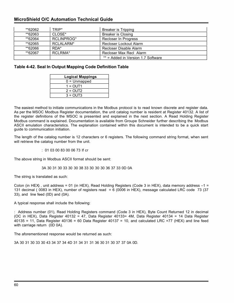
MicroShield O/C Automation Technical Guide
60
**62062 TRIP* Breaker is Tripping**62063 CLOSE* Breaker is Closing**62064 RCLINPROG* Recloser In Progress**62065 RCLALARM* Recloser Lockout Alarm**62066 RDA* Recloser Disable Alarm**62067 RCLRMA* Recloser Max Recl Alarm
** = Added in Version 1.7 Software
Table 4-42. Seal In Output Mapping Code Definition Table
Logical Mappings0 = Unmapped1 = OUT12 = OUT23 = OUT3
The easiest method to initiate communications in the Modbus protocol is to read known discrete and register data.As per the MSOC Modbus Register documentation, the unit catalog number is resident at Register 40132. A list ofthe register definitions of the MSOC is presented and explained in the next section. A Read Holding RegisterModbus command is explained. Documentation is available from Groupe Schneider further describing the ModbusASCII emulation characteristics. The explanation contained within this document is intended to be a quick startguide to communication initiation.
The length of the catalog number is 12 characters or 6 registers. The following command string format, when sentwill retrieve the catalog number from the unit.
: 01 03 00 83 00 06 73 lf cr
The above string in Modbus ASCII format should be sent:
3A 30 31 30 33 30 30 38 33 30 30 30 36 37 33 0D 0A
The string is translated as such:
Colon (in HEX) , unit address = 01 (in HEX), Read Holding Registers (Code 3 in HEX), data memory address –1 =131 decimal ( 0083 in HEX), number of registers read = 6 (0006 in HEX), message calculated LRC code 73 (3733), and line feed (0D) and (0A).
A typical response shall include the following:
: Address number (01), Read Holding Registers command (Code 3 in HEX), Byte Count Returned 12 in decimal(OC in HEX), Data Register 40132 = 47, Data Register 40133= 4M, Data Register 40134 = 14 Data Register40135 = 11, Data Register 40136 = 60 Data Register 40137 = 10, and calculated LRC =77 (HEX) and line feedwith carriage return (0D 0A).
The aforementioned response would be returned as such:
3A 30 31 30 33 30 43 34 37 34 4D 31 34 31 31 36 30 31 30 37 37 0A 0D.
MicroShield O/C Automation Technical Guide
61
Calculation of the LRC (Longitudinal Redundancy Code)Modbus ASCII protocol uses a Longitudinal Redundancy Code to verify correct reception of the command. Thiserror check is used in addition to the parity option (used by the UART in the PC) and other data such as the bytecount which verifies data returned. The process for calculation of the checksum is described as such:
1. Add all bytes in the message except for the colon, line feed, and carriage return. Exclude the LRCchecksum, which in included in the message structure.
2. Invert all bits in the word after the addition.3. Add 1 to the inverted result. This is the checksum.
An example is as follows:Command sent:
3A 30 31 30 33 30 30 38 33 30 30 30 36 37 33 0D 0A
Decode of the data from ASCII to HEX yields.
: 01 03 00 83 00 06 73 lf cr
The decoded LRC checksum is 73. The calculation of the checksum is as such:
1. Neglect the colon (3A) and the lf (Line Feed 0A) and cr (Carriage Return OD). This decreases thestring to 01 03 00 83 06 73.
2. The LRC checksum 73 (37 33 in ASCII) should also be saved for comparison to the original datastring. The string for LRC calculation is 01 03 00 83 00 06.
3. The byte data should be added thus 01 + 03 + 00 +83 + 00 + 06 = 8D in HEX. Notice that thebytes have been decoded from ASCII before performing the addition.
4. A Two’s compliment must be performed on the number to determine the LRC Checksum.Inversion of the number 8D hex yields 72 HEX.
5. To complete the Two’s compliment addition for accurate compilation of the checksum 1 HEX mustbe added to the inverted bits to yield 72 + 1 = 73 HEX. Thus the two calculated values agree.
Please reference the Modicon Modbus documentation for additional command configuration on each data type(0X, 1X, 4X and 6X read write capabilities).
MSOC Modbus Exception Response Analysis
If the MSOC does not understand the command sent to the device or if the command is sent in the wrong format,the MSOC shall generate an exception response. A Modbus exception response is in the format of that shown inFigure 4-26. As illustrated, the function code is “ANDed” with 80 HEX. Following the modified function code, anexception code byte will follow. The customary LRC and terminator of a Carriage Return and Line feed willterminate the communication string.
Table 4-43 shall list the standard Modbus Exception Codes and Table 4-45 lists the exception codes as the MSOCreports them. Notice that the MSOC does not report its exception codes as per the Modbus standard definedcodes.
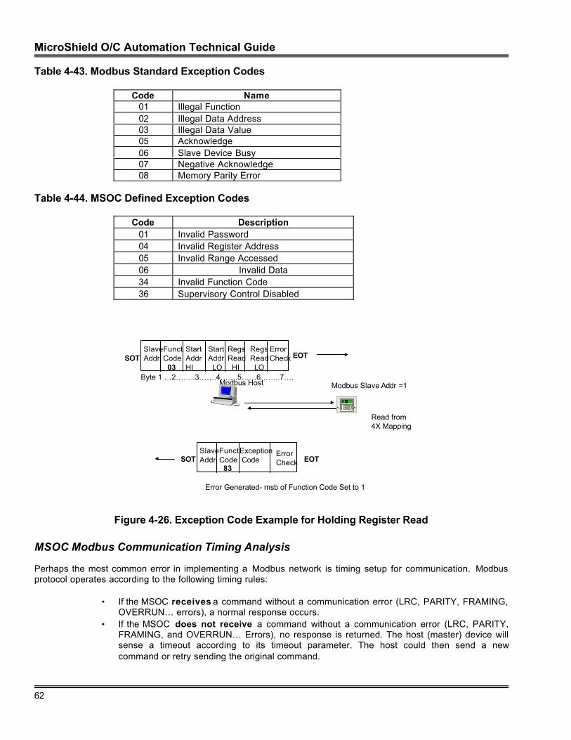
MicroShield O/C Automation Technical Guide
62
Table 4-43. Modbus Standard Exception Codes
Code Name01 Illegal Function02 Illegal Data Address03 Illegal Data Value05 Acknowledge06 Slave Device Busy07 Negative Acknowledge08 Memory Parity Error
Table 4-44. MSOC Defined Exception Codes
Code Description01 Invalid Password04 Invalid Register Address05 Invalid Range Accessed06 Invalid Data34 Invalid Function Code36 Supervisory Control Disabled
Modbus Host Modbus Slave Addr =1
Read from 4X Mapping
SlaveAddr.
Funct.Code 03
StartAddrHI
Start Addr LO
RegsRead HI
RegsRead LO
ErrorCheck EOTSOT
Byte 1 …2……..3…….4…….5……6……..7….
SlaveAddr.
Funct.Code 83
Exception Code
ErrorCheck EOTSOT
E
C
NetworkPartnerV1.0
Error Generated- msb of Function Code Set to 1
Figure 4-26. Exception Code Example for Holding Register Read
MSOC Modbus Communication Timing Analysis
Perhaps the most common error in implementing a Modbus network is timing setup for communication. Modbusprotocol operates according to the following timing rules:
• If the MSOC receives a command without a communication error (LRC, PARITY, FRAMING,OVERRUN… errors), a normal response occurs.
• If the MSOC does not receive a command without a communication error (LRC, PARITY,FRAMING, and OVERRUN… Errors), no response is returned. The host (master) device willsense a timeout according to its timeout parameter. The host could then send a newcommand or retry sending the original command.
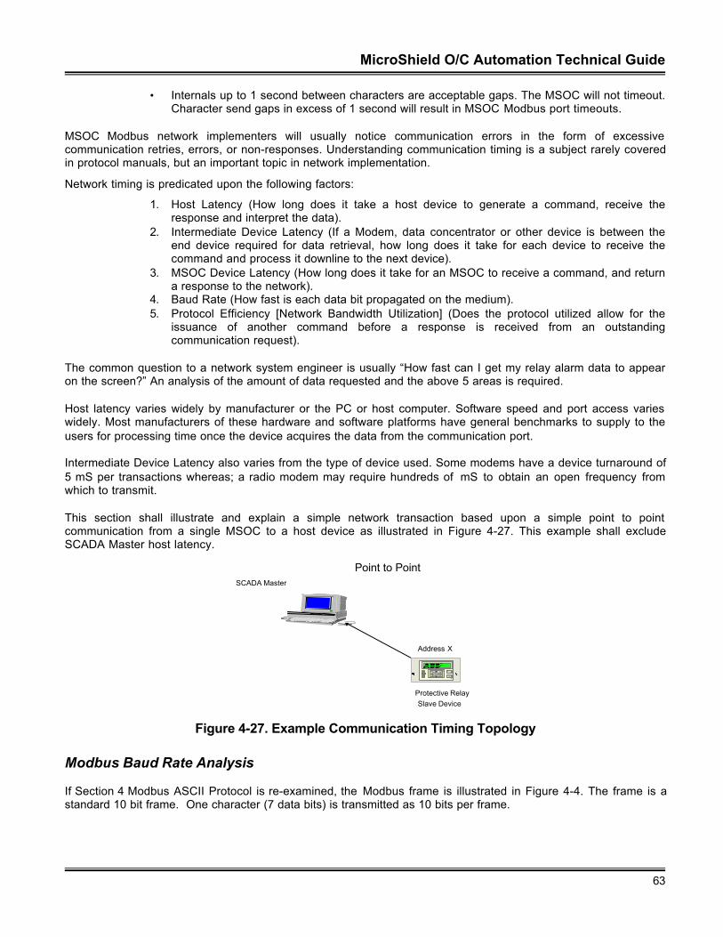
MicroShield O/C Automation Technical Guide
63
• Internals up to 1 second between characters are acceptable gaps. The MSOC will not timeout.Character send gaps in excess of 1 second will result in MSOC Modbus port timeouts.
MSOC Modbus network implementers will usually notice communication errors in the form of excessivecommunication retries, errors, or non-responses. Understanding communication timing is a subject rarely coveredin protocol manuals, but an important topic in network implementation.
Network timing is predicated upon the following factors:
1. Host Latency (How long does it take a host device to generate a command, receive theresponse and interpret the data).
2. Intermediate Device Latency (If a Modem, data concentrator or other device is between theend device required for data retrieval, how long does it take for each device to receive thecommand and process it downline to the next device).
3. MSOC Device Latency (How long does it take for an MSOC to receive a command, and returna response to the network).
4. Baud Rate (How fast is each data bit propagated on the medium).5. Protocol Efficiency [Network Bandwidth Utilization] (Does the protocol utilized allow for the
issuance of another command before a response is received from an outstandingcommunication request).
The common question to a network system engineer is usually “How fast can I get my relay alarm data to appearon the screen?” An analysis of the amount of data requested and the above 5 areas is required.
Host latency varies widely by manufacturer or the PC or host computer. Software speed and port access varieswidely. Most manufacturers of these hardware and software platforms have general benchmarks to supply to theusers for processing time once the device acquires the data from the communication port.
Intermediate Device Latency also varies from the type of device used. Some modems have a device turnaround of5 mS per transactions whereas; a radio modem may require hundreds of mS to obtain an open frequency fromwhich to transmit.
This section shall illustrate and explain a simple network transaction based upon a simple point to pointcommunication from a single MSOC to a host device as illustrated in Figure 4-27. This example shall excludeSCADA Master host latency.
SCADA Master
Protective Relay
Point to Point
Slave Device
Address X
E
C
Network
PartnerV1.0
Figure 4-27. Example Communication Timing Topology
Modbus Baud Rate Analysis
If Section 4 Modbus ASCII Protocol is re-examined, the Modbus frame is illustrated in Figure 4-4. The frame is astandard 10 bit frame. One character (7 data bits) is transmitted as 10 bits per frame.
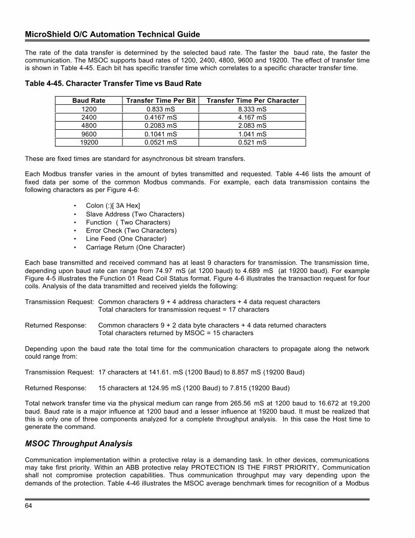
MicroShield O/C Automation Technical Guide
64
The rate of the data transfer is determined by the selected baud rate. The faster the baud rate, the faster thecommunication. The MSOC supports baud rates of 1200, 2400, 4800, 9600 and 19200. The effect of transfer timeis shown in Table 4-45. Each bit has specific transfer time which correlates to a specific character transfer time.
Table 4-45. Character Transfer Time vs Baud Rate
Baud Rate Transfer Time Per Bit Transfer Time Per Character1200 0.833 mS 8.333 mS2400 0.4167 mS 4.167 mS4800 0.2083 mS 2.083 mS9600 0.1041 mS 1.041 mS19200 0.0521 mS 0.521 mS
These are fixed times are standard for asynchronous bit stream transfers.
Each Modbus transfer varies in the amount of bytes transmitted and requested. Table 4-46 lists the amount offixed data per some of the common Modbus commands. For example, each data transmission contains thefollowing characters as per Figure 4-6:
• Colon (:)[ 3A Hex]• Slave Address (Two Characters)• Function ( Two Characters)• Error Check (Two Characters)• Line Feed (One Character)• Carriage Return (One Character)
Each base transmitted and received command has at least 9 characters for transmission. The transmission time,depending upon baud rate can range from 74.97 mS (at 1200 baud) to 4.689 mS (at 19200 baud). For exampleFigure 4-5 illustrates the Function 01 Read Coil Status format. Figure 4-6 illustrates the transaction request for fourcoils. Analysis of the data transmitted and received yields the following:
Transmission Request: Common characters 9 + 4 address characters + 4 data request charactersTotal characters for transmission request = 17 characters
Returned Response: Common characters 9 + 2 data byte characters + 4 data returned charactersTotal characters returned by MSOC = 15 characters
Depending upon the baud rate the total time for the communication characters to propagate along the networkcould range from:
Transmission Request: 17 characters at 141.61. mS (1200 Baud) to 8.857 mS (19200 Baud)
Returned Response: 15 characters at 124.95 mS (1200 Baud) to 7.815 (19200 Baud)
Total network transfer time via the physical medium can range from 265.56 mS at 1200 baud to 16.672 at 19,200baud. Baud rate is a major influence at 1200 baud and a lesser influence at 19200 baud. It must be realized thatthis is only one of three components analyzed for a complete throughput analysis. In this case the Host time togenerate the command.
MSOC Throughput Analysis
Communication implementation within a protective relay is a demanding task. In other devices, communicationsmay take first priority. Within an ABB protective relay PROTECTION IS THE FIRST PRIORITY. Communicationshall not compromise protection capabilities. Thus communication throughput may vary depending upon thedemands of the protection. Table 4-46 illustrates the MSOC average benchmark times for recognition of a Modbus
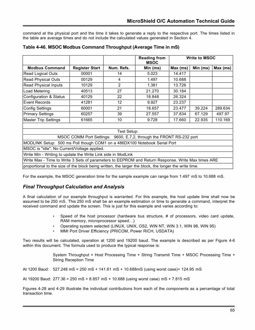
MicroShield O/C Automation Technical Guide
65
command at the physical port and the time it takes to generate a reply to the respective port. The times listed inthe table are average times and do not include the calculated values generated in Section 4.
Table 4-46. MSOC Modbus Command Throughput (Average Time in mS)
Reading fromMSOC
Write to MSOC
Modbus Command Register Start Num. Refs. Min (ms) Max (ms) Min (ms) Max (ms)Read Logical Outs 00001 14 5.023 14.417Read Physical Outs 00129 4 1.497 10.688Read Physical Inputs 10129 2 1.381 13.726Load Metering 40513 27 21.270 30.184Configuration & Status 40129 22 18.848 26.324Event Records 41281 12 9.927 23.237Config Settings 60001 21 18.657 23.477 39.224 289.634Primary Settings 60257 39 27.557 37.834 67.129 497.97Master Trip Settings 61665 10 9.728 17.660 22.935 110.169
Test Setup:MSOC COMM Port Settings: 9600, E,7,2, through the FRONT RS-232 port
MODLINK Setup: 500 ms Poll though COM1 on a 486DX100 Notebook Serial PortMSOC is "idle", No Current/Voltage applied.Write Min - Writing to update the Write Link side in ModLinkWrite Max - Time to Write 3 Sets of parameters to EEPROM and Return Response. Write Max times AREproportional to the size of the block being written, the larger the block, the longer the write time.
For the example, the MSOC generation time for the sample example can range from 1.497 mS to 10.688 mS.
Final Throughput Calculation and Analysis
A final calculation of our example throughput is warranted. For this example, the host update time shall now beassumed to be 250 mS. This 250 mS shall be an example estimation or time to generate a command, interpret thereceived command and update the screen. This is just for this example and varies according to:
• Speed of the host processor (hardware bus structure, # of processors, video card update,RAM memory, microprocessor speed…)
• Operating system selected (LINUX, UNIX, OS2, WIN NT, WIN 3.1, WIN 98, WIN 95)• MMI Port Driver Efficiency (PRICOM, Power RICH, USDATA)
Two results will be calculated, operation at 1200 and 19200 baud. The example is described as per Figure 4-6within this document. The formula used to produce the typical response is:
System Throughput = Host Processing Time + String Transmit Time + MSOC Processing Time +String Reception Time
At 1200 Baud: 527.248 mS = 250 mS + 141.61 mS + 10.688mS (using worst case)+ 124.95 mS
At 19200 Baud: 277.36 = 250 mS + 8.857 mS + 10.688 (using worst case) mS + 7.815 mS
Figures 4-28 and 4-29 illustrate the individual contributions from each of the components as a percentage of totaltransaction time.
MicroShield O/C Automation Technical Guide
66
Percent Contribution at 1200 Baud
RCV Latency24%
MSOC Latency1%
TX Baud Latency
27%
Host Latency48%
RCV Latency
MSOC Latency
TX Baud Latency
Host Latency
Figure 4-27. Network Throughput Analysis at 1200 Baud
Percent Contribution at 19200 Baud
Host Latency93%
TX Baud Latency
3%
RCV Latency3%
MSOC Latency
1%
RCV Latency
MSOC Latency
TX Baud Latency
Host Latency
Figure 4-28. Network Throughput Analysis at 19200 Baud
Analysis of the simple example yields a few points to be considered when analyzing system throughput. Eachelement involved in communication timing contributes significantly to overall throughput. If the host executed andupdated faster, overall throughput could be improved. If intermediate devices were inserted within the network,transaction time would increase proportionately. Baud rate is only one of many contributing factors in calculatingsystem throughput. If one network access was required for retrieval of system data, overall network efficiencywould be improved. If in a networked system, the protocol utilized would allow for additional data requestcommands while the slave device is processing a response, Network throughput time would be improved.
Virtual treatises have been written on improving system throughput and data updates. This simple exampleillustrates and allows the user to calculate system throughput times. This is especially critical so that the systemuser will not be surprised with overall system response.

MicroShield O/C Automation Technical Guide
67
ABB has implemented features within the protective relay to maintain system data integrity. Latched bit status,momentary change detect are a few features implemented within the various implementations of the Modbusprotocol.
MSOC ASCII Protocol
Prior to the establishment of industry standard protocols, each vendor of utility equipment designed and includedas part of the product a vendor specific protocol. These protocols were primarily based upon ASCII protocol. TheMSOC has, in addition to the Modbus ASCII protocol, a Native ASCII protocol included on the standard product.
There are two different versions of Native the ASCII Communications for the MicroShield. The first is called “FastASCII”. This provides a fixed command set that is defined to allow the user to develop a simple program tocommunicate with the MicroShield. These commands are documented in this specification. This allows a host tocommunicate to the MSOC in a semi-automated method using proprietary device specific protocols.
The other ASCII Mode, “Menu ASCII”, is a user interactive based mode of communications. The User will bepresented with screens of data and be required to respond in order to change parameters in the MicroShield.Usually implementers will attach a dumb terminal emulator to the unit allowing the modification and access ofMSOC via a network viewing the specific parameters via a computer screen.
“Menu ASCII” was developed for users to configure the MSOC via a computer terminal instead of by the LCDMMI screen incorporated in the MSOC unit. As with the Modbus Protocol, Native MSOC ASCII is a Master-SlaveProtocol. MSOC Native ASCII protocol has two sets of emulation “Menu Mode” and “Fast ASCII Mode”. Each ofthese sets has two subsets.
Subset 1 is via the RS 232 front port. No address is sent with the command. Communications through this port(as dictated by the protocol and the physical interface) is point to point only. This makes it useful for use with adumb terminal emulator.
Subset 2 is via the RS 485 rear port. An address command is sent. Each device determines that it is an addresscommand (since the command is in capital letter format only). Once the device establishes that its addresscommand has been sent, it will listen and interpret all commands sent along the network. The device will stopinterpreting commands when another address command is sent with differing parameters.
MSOC Native ASCII “Menu Mode”
Menu mode is the state in which the MSOC may communicate via a “dumb terminal emulator”. The MSOCpresent a menu to the operator via the terminal to which it is connected. The default state for the MSOC is MSOCNative ASCII “Fast Mode” described in Section 4. As explained in Section 3, the local echo setup parametershould be set to “YES” when configuring the port. This will set the MSOC to echo whatever is typed by theoperator, thus allowing visualization on the terminal screen. Most terminals require duplex operation as such.
The MSOC Native ASCII “Menu Mode” operates via the front RS 232 port or the rear RS 485 port. The front portrequires no address be sent for communication initiation strings, whereas communication through the rear portrequires the string ADDR <xxx> <CR> <LF> (NOTE: The “ADDR” MUST BE upper case for proper reception) besent to enable the unit to listen to communication ASCII strings sent along the communication network. The frontport requires only a line feed carriage return <LF> <CR> to be sent to the unit. The front port is described as apoint to point connection port (not suitable for multiple device connection). The rear port is described as a networkport.
One the MSOC receives the initialization string; the following banner will be issued to the unit:
MicroShield O/C,0010,474M04116000, 974677,1.00,1.00Type ‘menu’ to enter Menu Mode
Where:MicroShield O/C is the Product’s Name
MicroShield O/C Automation Technical Guide
68
0010 is the Unit’s Address, for verification of the connection474M. . . is the Unit’s Catalog Number9746. . . is the Unit’s Serial Number1.00 is the Software Version for the Main CPU1.00 is the Software Version for the Comm CPU
All commands in MSOC Native ASCII Menu Mode are in lower case. To enter “menu mode” the user must type“menu” (omit quotation marks).
MSOC Native ASCII “Menu Mode” Terminal Configuration
ASCII communication through a “dumb terminal” requires configuration of the terminal. Popular terminalemulators are listed below according to the operating system:
• DOS – Procomm• Windows 3.1 – Terminal (Standard Accessory with Windows 3.1)• Windows 95, NT or 98 – Hyperterminal
Application Example Configuration: Example Hyperterminal settings for Windows 95, NT or 98 are listedbelow for a personal computer connected to an MSOC on Com port 1 through the RS 232 port on the front of theMSOC:
Connect Using PC port Com 1Com Port Settings:
9600 Baud8 data Bitsno Parity1 Stop Bitno Flow Control
Settings:Function Arrow and Control keys as Terminal KeysVT 100 Terminal EmulationBackscroll buffer lines 100Beep three times when connecting or disconnecting
Terminal Modes:Cursor Block BlinkKeypad Application ModeCursor Keypad ModeCharacter Set ASCII
ASCII Send Setup:Send line ends with line feedEcho Typed Characters Locally (Set Local Echo Off in the MSOC)Line delay: 5 millisecondsCharacter delay 5 milliseconds
ASCII ReceivingEnable line wrap function
NOTE: The MSOC should be set to the same Com Port Settings as listed above. Consult Section 2 and 3 forMSOC cabling and port configuration procedures. Consult the Microsoft operating system documentation forHyperterminal configuration instructions.
It should be noted that other settings may be used to accomplish the same connectivity. The above settings areintended to serve as an example only.
MicroShield O/C Automation Technical Guide
69
MSOC Native ASCII “Menu Mode” Command Format
The menu mode requires the user to type a single command letter to the MSOC. The letter may be in upper orlower case. Since the terminal setup (Section 4) appends a line feed (<lf> HEX code OD) to the enter key(carriage return <cr>) HEX code OA), the command is interpreted by the MSOC device. Figure 4-30 lists themenu structure viewed by the operator on the terminal screen when unit communications are established.
MAIN MENU[M]eter Menu[S]how Settings[C]hange Settings[R]ecords Menu[O]perations Menu[T]est Menu[U]nit Info[E]xit Menu Mode
Figure 4-30. Main Menu Selection Screen
The operator must select one of the letters enclosed within the brackets. In the Menu Mode UPPERCASE orLOWERCASE letters may be used. If [M]eter Menu is selected (M or m) the screen depicted in Figure 4-31 shallbe displayed to the operator.
Figure 4-31 also includes submenus and example displays for each selection. Additionally, the followingkeystrokes are valid:
• Return (configured to give a <cr> <lf>) shall advance to the next submenu selection.• Any menu selection as depicted by the arrows.
If the MSOC has no voltage inputs, then voltage and power values are not available from the relay as depicted inFigure 4-31. If voltage is included within the MSOC, Volt per phase values (as indicated on the front panel) will bedisplayed. Power values will also be calculated and reported to the operator.
MAIN MENU[M]eter Menu[S]how Settings[C]hange Settings[R]ecords Menu[O]perations Menu[T]est Menu[U]nit Info
[E]xit Menu Mode
Load [C]urrent Values[V]oltage Values[P]ower Values[D]emand Values[A]ll Load Values
[B]ack to Main Menu
Load Currents
Ia:181Ib:180Ic:181In:180 >
[R]epeat Display[M]eter Menu
[B]ack to Main Menu
Load Voltages
N/A * >
[r]epeat Display[m]eter Menu
[b]ack to Main Menu* = note for MSOC without Voltage Inputs
Power
N/A * >
[R]epeat Display[M]eter Menu
[B]ack to Main Menu* = note for MSOC without Voltage Inputs
Demand Values
Ia:63Ib:63Ic:63In:61 >
[R]epeat Display[M]eter Menu[B]ack to Main Menu
Load Values
Ia:180Ib:181Ic:181In:180 >
[R]epeat Display[M]eter Menu[B]ack to Main Menu
Figure 4-31. Meter Menu Submenu Selections
Meter display values are not updated continuously on the screen. The values displayed are those provided by theunit as a “snapshot” when the values are requested by the host.
If the operator selects the [S]how Settings screen, from the Main Menu, various selections shall be displayedupon the operator terminal. The screens displayed are illustrated in Figures 4-31 and 4-32. The settings can only
MicroShield O/C Automation Technical Guide
70
be viewed by the operator in this screen. Figures 4-30 and 4-33 also display example values visible when thesubmenus are selected. These menus are analogous to the “Fast ASCII” command types found in Table 4-47 ofthis guide.
MAIN MENU[M]eter Menu[S]how Settings[C]hange Settings[R]ecords Menu[O]perations Menu[T]est Menu[U]nit Info[E]xit Menu Mode
Show Settings
[P]rotective Settings[C]onfiguration SettingsProgrammable [I]nputsProgrammable [O]utputs[M]aster Trip SettingsCommu[N]ication SettingsReal [T]ime Clock[R]ecloser SettingsCounters [S]ettings
[B]ack to Main Menu
> P
51LT: LT Inv51LT PU: 2.0051LT TD: 1.0051P: LT Inv51P PU: 6.0051P TD: 1.0050P: Definite50P PUx: 2.0050P Dly: 1.0051N: LT Inv51N PU: 2.0051N TD: 1.0050N: Definite50N PUx: 2.0050N Dly: 1.00 >
Press Enter to continue.
> C
Ph Rat: 100N Rat: 100Trip Fail: 60Dmd Const: 30Reset: InstCld Ld Md: DIS
Clse Fail: 18
> I
51LT: Unmapped51P: Unmapped50P: Unmapped51N: Unmapped50N: Unmapped52a: Unmapped52b: UnmappedTRIP: UnmappedCLOS: Unmapped43a: UnmappedEXRI: UnmappedZSC: Unmapped
DTL: Unmapped
> O
51LT: Unmapped51P: Unmapped50P: Unmapped51N: Unmapped50N: UnmappedPUA: OUT1FAIL: OUT2CBFAIL: UnmappedTRIP: UnmappedCLOSE: UnmappedRIP: UnmappedRLA: UnmappedRDA: UnmappedRMAX: Unmapped
Figure 4-32. Show Settings Menu Selections
MAIN MENU[M]eter Menu[S]how Settings[C]hange Settings[R]ecords Menu[O]perations Menu[T]est Menu[U]nit Info[E]xit Menu Mode
Show Settings
[P]rotective Settings[C]onfiguration SettingsProgrammable [I]nputsProgrammable [O]utputs[M]aster Trip SettingsCommu[N]ication SettingsReal [T]ime Clock[R]ecloser SettingsCounters [S]ettings
[B]ack to Main Menu
> M
51LT: ON51P: ON50P: ON51N: ON50N: ON >
Press Enter to continue.
> N
Addr: 1FP BRate: 9600FP Frm: N,8,1FP Prot: ASCIILocal Echo: ONRP BRate: 9600RP Frm: N,8,1RP Prot: ASCII
> T
00:00:00 00/00/0000
> Show Settings
> R
R1 Op Tm: LKOR1 50P En: ENBR1 50N En: ENBR1 51N En: ENBR1 51LT En: ENBR1 51P LO: ENB >
> S
Brk Oper: 5KSIA: 1KSIB: 1KSIC: 179-1: 079-2: 079-3: 079-4: 0Tot Rcl: 0OC TRIP: 7Suc Rcl: 0 >
Press Enter to continue.
Figure 4-33. Show Settings Menu Selections (continued)
MicroShield O/C Automation Technical Guide
71
If the show settings command are selected, the command “Press Enter to Continue” shall be displayed. If enter isdepressed on the keyboard, the Show Settings screen shall be displayed. The Show Settings display allowsoperator visualization of the parameters programmed in the MSOC.Selection of [C]hange Settings shall display options for changing the relay settings through the communicationinterface. The same selections may be changed via the MSOC front panel interface also. The following tipsshould be remembered when operating in the [C]hange Settings menu:
• Password is required (the default is four spaces). Three tries are allowed. If the password isrejected, control is transferred to the previous level of menu selection.
• A <cr> <lf> (configured as depressing the enter key on the terminal keyboard), shall advancethe display to the next selection without changing the value in the presented and presentlydisplayed item.
• If the user types an “=” sign, the menu shall advance to the “SAVE SETTINGS” prompt andwait for the user to answer the query with a “Y” or “N” response.
• If the user types a value outside of the valid range of responses as indicated in the menuselection, a response of “INVALID SELECTION” will be displayed to the operator.
MAIN MENU[M]eter Menu[S]how Settings[C]hange Settings[R]ecords Menu[O]perations Menu[T]est Menu[U]nit Info[E]xit Menu Mode
Change Settings
[P]rotective Settings[C]onfiguration SettingsProgrammable [I]nputsProgrammable [O]utputs[M]aster Trip SettingsCommu[N]ication SettingsReal [T] ime Clock[R]ecloser SettingsCounters [S]ettings
[B]ack to Main Menu
> P
Enter Password:*
Enter '=' when ready to save. > 51LT: LT Inv ( ldef lx lv ln vlx vlv vln )Change to: > ln51LT PU: 2.00 ( 1.50 - 12.00)Change to: > 2.0051LT TD: 1.00 ( 1.00 - 10.00)Change to: > 1.0051P: LT Inv ( def lx lv ln x v n sn )Change to: > ln 51P PU: 6.00 ( 1.50 - 12.00)Change to: > 6.0051P TD: 1.00 ( 1.00 - 10.00)Change to: > 1.0050P: Definite ( def std sn )Change to: > def50P PUx: 2.00 ( 1.00 - 20.00)Change to: > 2.00
50P Dly: 1.00 ( 0.00 - 30.00)Change to: > 1.0051N: LT Inv ( def lx lv ln x v n sn )Change to: > ln51N PU: 2.00 ( 0.50 - 4.00)Change to: > 2.0051N TD: 1.00 ( 1.00 - 10.00)Change to: > 1.0050N: Definite ( def std sn )Change to: > def50N PUx: 2.00 ( 1.00 - 20.00)Change to: > 2.0050N Dly: 1.00 ( 0.00 - 30.00)Change to:> 1.00
Save Settings? [Y]es / [N]o
> y
Settings Saved
Figure 4-34. Example Change Setting Responses for Submenu [P]rotective Settings
The example shown in Figure 4-34 is an example of the operator selecting each response within the rangepresented within the menu item selections. The MSOC indicates that the settings have been selected and saved.
MicroShield O/C Automation Technical Guide
72
MAIN MENU[M]eter Menu[S]how Settings[C]hange Settings[R]ecords Menu[O]perations Menu[T]est Menu[U]nit Info[E]xit Menu Mode
Change Settings
[P]rotective Settings[C]onfiguration SettingsProgrammable [I]nputsProgrammable [O]utputs[M]aster Trip SettingsCommu[n]ication SettingsReal [T]ime Clock[R]ecloser SettingsCounters [S]ettings
[B]ack to Main Menu
> C
Enter Password:*
Enter '=' when ready to save. > Ph Rat: 100 ( 1 - 2000)Change to: >N Rat: 10 ( 1 - 2000)Change to:>Trip Fail: 60 ( 5 - 60)Change to: >Dmd Const: 30 ( 15 30 60 )Change to: >Reset: Inst ( ins dly )Change to: >Cld Ld Md: DIS ( sec min )Change to: >Clse Fail: 3 ( 3 - 999)Change to: >Save Settings? [Y]es / [N]o
> y
Settings Saved
Figure 4-35. Example Change Setting Responses for Submenu [C]onfiguration Settings
Figure 4-35 illustrates an example menu screen for default settings within the MSOC. The operator in this casehas entered a <cr> <lf> (in this case hyperterminal is configured to give this string when the keyboard’s enter keyis depressed).
>I
Enter Password:*
Enter '=' when ready to save. > 51LT: Unmapped ( nm in1 in2 1ad2 1or2 )Change to: >51P: Unmapped ( nm in1 in2 1ad2 1or2 )Change to: > 50P: Unmapped ( nm in1 in2 1ad2 1or2 )Change to: >51N: Unmapped ( nm in1 in2 1ad2 1or2 )Change to: >50N: Unmapped ( nm in1 in2 1ad2 1or2 )Change to: >52a: Unmapped ( nm in1 in2 1ad2 1or2 )Change to: >52b: Unmapped ( nm in1 in2 1ad2 1or2 )Change to: >TRIP: Unmapped ( nm in1 in2 1ad2 1or2 )Change to: >
CLOS: Unmapped ( nm in1 in2 1ad2 1or2 )Change to: >43a: Unmapped ( nm in1 in2 1ad2 1or2 )Change to: >EXRI: Unmapped ( nm in1 in2 1ad2 1or2 )Change to: >ZSC: Unmapped ( nm in1 in2 1ad2 1or2 )Change to: >DTL: Unmapped ( nm in1 in2 1ad2 1or2 )Change to: >
Save Settings? [Y]es / [N]o
MAIN MENU[M]eter Menu[S]how Settings[C]hange Settings[R]ecords Menu[O]perations Menu[T]est Menu[U]nit Info[E]xit Menu Mode
Change Settings
[P]rotective Settings[C]onfiguration SettingsProgrammable [I]nputsProgrammable [O]utputs[M]aster Trip SettingsCommu[N]ication SettingsReal [T]ime Clock[R]ecloser SettingsCounters [S]ettings
[B]ack to Main Menu
Figure 4-36. Example Change Setting Responses for Submenu Programmable [I]nputs
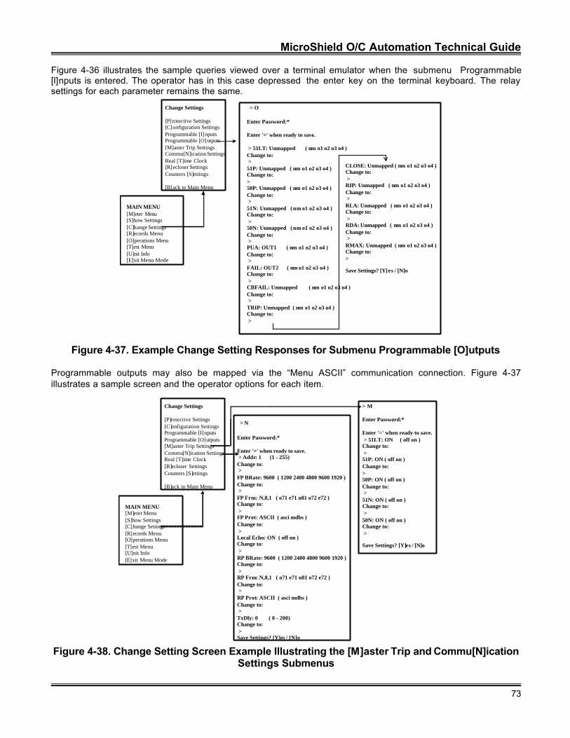
MicroShield O/C Automation Technical Guide
73
Figure 4-36 illustrates the sample queries viewed over a terminal emulator when the submenu Programmable[I]nputs is entered. The operator has in this case depressed the enter key on the terminal keyboard. The relaysettings for each parameter remains the same.
MAIN MENU[M]eter Menu[S]how Settings[C]hange Settings[R]ecords Menu[O]perations Menu[T]est Menu[U]nit Info[E]xit Menu Mode
Change Settings
[P]rotective Settings[C]onfiguration SettingsProgrammable [I]nputsProgrammable [O]utputs[M]aster Trip SettingsCommu[N]ication SettingsReal [T]ime Clock[R]ecloser SettingsCounters [S]ettings
[B]ack to Main Menu
> O
Enter Password:*
Enter '=' when ready to save.
> 51LT: Unmapped ( nm o1 o2 o3 o4 )Change to: >51P: Unmapped ( nm o1 o2 o3 o4 )Change to:>50P: Unmapped ( nm o1 o2 o3 o4 )Change to: >51N: Unmapped ( nm o1 o2 o3 o4 )Change to: >50N: Unmapped ( nm o1 o2 o3 o4 )Change to: >PUA: OUT1 ( nm o1 o2 o3 o4 )Change to: >FAIL: OUT2 ( nm o1 o2 o3 o4 )Change to: >CBFAIL: Unmapped ( nm o1 o2 o3 o4 )Change to: >TRIP: Unmapped ( nm o1 o2 o3 o4 )Change to: >
CLOSE: Unmapped ( nm o1 o2 o3 o4 )Change to: >RIP: Unmapped ( nm o1 o2 o3 o4 )Change to: >RLA: Unmapped ( nm o1 o2 o3 o4 )Change to: >RDA: Unmapped ( nm o1 o2 o3 o4 )Change to: >RMAX: Unmapped ( nm o1 o2 o3 o4 )Change to:>
Save Settings? [Y]es / [N]o
Figure 4-37. Example Change Setting Responses for Submenu Programmable [O]utputs
Programmable outputs may also be mapped via the “Menu ASCII” communication connection. Figure 4-37illustrates a sample screen and the operator options for each item.
MAIN MENU[M]eter Menu[S]how Settings[C]hange Settings[R]ecords Menu[O]perations Menu[T]est Menu[U]nit Info[E]xit Menu Mode
Change Settings
[P]rotective Settings[C]onfiguration SettingsProgrammable [I]nputsProgrammable [O]utputs[M]aster Trip SettingsCommu[N]ication SettingsReal [T]ime Clock[R]ecloser SettingsCounters [S]ettings
[B]ack to Main Menu
> M
Enter Password:*
Enter '=' when ready to save. > 51LT: ON ( off on )Change to: >51P: ON ( off on )Change to:>50P: ON ( off on )Change to: >51N: ON ( off on )Change to: >50N: ON ( off on )Change to: >
Save Settings? [Y]es / [N]o
> N
Enter Password:*
Enter '=' when ready to save. > Addr: 1 (1 - 255)Change to: >FP BRate: 9600 ( 1200 2400 4800 9600 1920 )Change to: >FP Frm: N,8,1 ( o71 e71 n81 o72 e72 )Change to: >FP Prot: ASCII ( asci mdbs )Change to: >Local Echo: ON ( off on )Change to: >RP BRate: 9600 ( 1200 2400 4800 9600 1920 )Change to: >RP Frm: N,8,1 ( o71 e71 n81 o72 e72 )Change to: >RP Prot: ASCII ( asci mdbs )Change to: >TxDly: 0 ( 0 - 200)Change to: >Save Settings? [Y]es / [N]o
Figure 4-38. Change Setting Screen Example Illustrating the [M]aster Trip and Commu[N]icationSettings Submenus
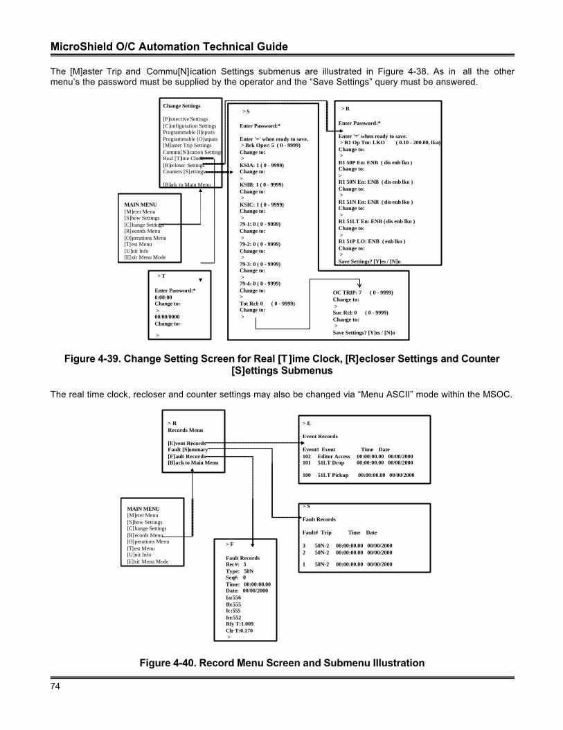
MicroShield O/C Automation Technical Guide
74
The [M]aster Trip and Commu[N]ication Settings submenus are illustrated in Figure 4-38. As in all the othermenu’s the password must be supplied by the operator and the “Save Settings” query must be answered.
> T
Enter Password:*0:00:00Change to: >00/00/0000Change to:
>
MAIN MENU[M]eter Menu[S]how Settings[C]hange Settings[R]ecords Menu[O]perations Menu[T]est Menu[U]nit Info[E]xit Menu Mode
Change Settings
[P]rotective Settings[C]onfiguration SettingsProgrammable [I]nputsProgrammable [O]utputs[M]aster Trip SettingsCommu[N]ication SettingsReal [T]ime Clock[R]ecloser SettingsCounters [S]ettings
[B]ack to Main Menu
> R
Enter Password:*
Enter '=' when ready to save. > R1 Op Tm: LKO ( 0.10 - 200.00, lko)Change to: >R1 50P En: ENB ( dis enb lko )Change to:>R1 50N En: ENB ( dis enb lko )Change to: >R1 51N En: ENB ( dis enb lko )Change to: >R1 51LT En: ENB ( dis enb lko )Change to: >R1 51P LO: ENB ( enb lko )Change to: >Save Settings? [Y]es / [N]o
> S
Enter Password:*
Enter '=' when ready to save. > Brk Oper: 5 ( 0 - 9999)Change to: >KSIA: 1 ( 0 - 9999)Change to:>KSIB: 1 ( 0 - 9999)Change to: >KSIC: 1 ( 0 - 9999)Change to: >79-1: 0 ( 0 - 9999)Change to: >79-2: 0 ( 0 - 9999)Change to: >79-3: 0 ( 0 - 9999)Change to: >79-4: 0 ( 0 - 9999)Change to:>Tot Rcl: 0 ( 0 - 9999)Change to: >
OC TRIP: 7 ( 0 - 9999)Change to: >Suc Rcl: 0 ( 0 - 9999)Change to: >Save Settings? [Y]es / [N]o
Figure 4-39. Change Setting Screen for Real [T ]ime Clock, [R]ecloser Settings and Counter[S]ettings Submenus
The real time clock, recloser and counter settings may also be changed via “Menu ASCII” mode within the MSOC.
> RRecords Menu
[E]vent RecordsFault [S]ummary[F]ault Records[B]ack to Main Menu
MAIN MENU[M]eter Menu[S]how Settings[C]hange Settings[R]ecords Menu[O]perations Menu[T]est Menu[U]nit Info[E]xit Menu Mode
> F
Fault RecordsRec#: 3Type: 50NSeq#: 0Time: 00:00:00.00Date: 00/00/2000Ia:556Ib:555Ic:555In:552Rly T:1.009Clr T:0.170 >
> S
Fault Records
Fault# Trip Time Date
3 50N-2 00:00:00.00 00/00/20002 50N-2 00:00:00.00 00/00/2000
1 50N-2 00:00:00.00 00/00/2000
> E
Event Records
Event# Event Time Date 102 Editor Access 00:00:00.00 00/00/2000101 51LT Drop 00:00:00.00 00/00/2000
100 51LT Pickup 00:00:00.00 00/00/2000
Figure 4-40. Record Menu Screen and Submenu Illustration
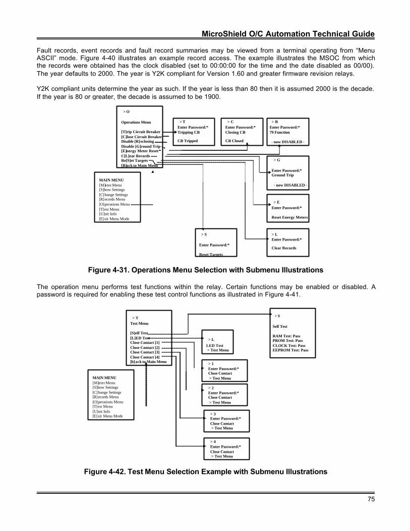
MicroShield O/C Automation Technical Guide
75
Fault records, event records and fault record summaries may be viewed from a terminal operating from “MenuASCII” mode. Figure 4-40 illustrates an example record access. The example illustrates the MSOC from whichthe records were obtained has the clock disabled (set to 00:00:00 for the time and the date disabled as 00/00).The year defaults to 2000. The year is Y2K compliant for Version 1.60 and greater firmware revision relays.
Y2K compliant units determine the year as such. If the year is less than 80 then it is assumed 2000 is the decade.If the year is 80 or greater, the decade is assumed to be 1900.
> O
Operations Menu
[T]rip Circuit Breaker[C]lose Circuit BreakerDisable [R]eclosingDisable [G]round Trip[E]nergy Meter ResetC[L]ear RecordsRe[S]et Targets[B]ack to Main Menu
MAIN MENU[M]eter Menu[S]how Settings[C]hange Settings[R]ecords Menu[O]perations Menu[T]est Menu[U]nit Info[E]xit Menu Mode
> TEnter Password:*Tripping CB
CB Tripped
> CEnter Password:*Closing CB
CB Closed
> REnter Password:*79 Function
- now DISABLED -
> G
Enter Password:*Ground Trip
- now DISABLED -
> EEnter Password:*
Reset Energy Meters
> LEnter Password:*
Clear Records
> S
Enter Password:*
Reset Targets
Figure 4-31. Operations Menu Selection with Submenu Illustrations
The operation menu performs test functions within the relay. Certain functions may be enabled or disabled. Apassword is required for enabling these test control functions as illustrated in Figure 4-41.
MAIN MENU[M]eter Menu[S]how Settings[C]hange Settings[R]ecords Menu[O]perations Menu[T]est Menu[U]nit Info[E]xit Menu Mode
> TTest Menu
[S]elf Test[L]ED TestClose Contact [1]Close Contact [2]Close Contact [3]Close Contact [4][b]ack to Main Menu
> S
Self Test
RAM Test: PassPROM Test: PassCLOCK Test: PassEEPROM Test: Pass
> 1Enter Password:*Close Contact > Test Menu
> LLED Test > Test Menu
> 4Enter Password:*Close Contact > Test Menu
> 2Enter Password:*Close Contact > Test Menu
> 3Enter Password:*Close Contact > Test Menu
Figure 4-42. Test Menu Selection Example with Submenu Illustrations
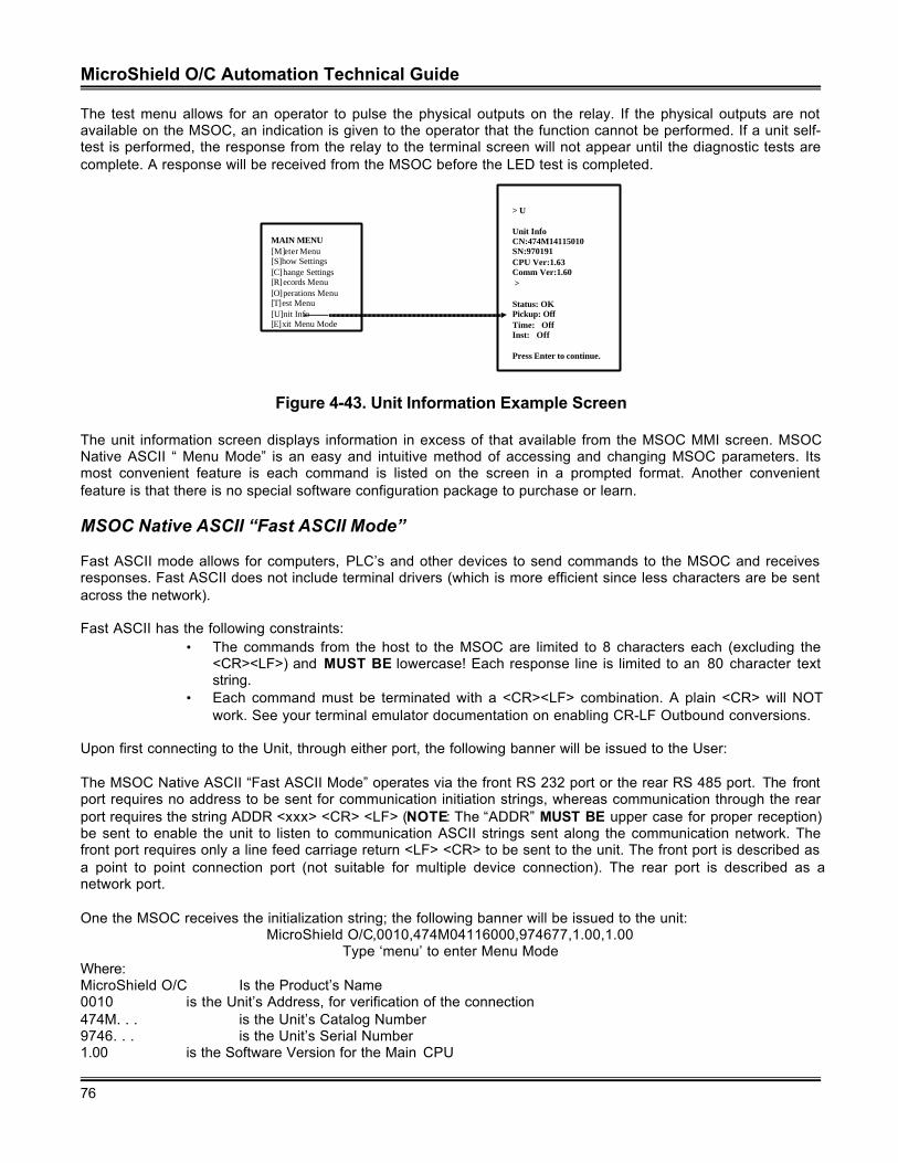
MicroShield O/C Automation Technical Guide
76
The test menu allows for an operator to pulse the physical outputs on the relay. If the physical outputs are notavailable on the MSOC, an indication is given to the operator that the function cannot be performed. If a unit self-test is performed, the response from the relay to the terminal screen will not appear until the diagnostic tests arecomplete. A response will be received from the MSOC before the LED test is completed.
MAIN MENU[M]eter Menu[S]how Settings[C]hange Settings[R]ecords Menu[O]perations Menu[T]est Menu[U]nit Info[E]xit Menu Mode
> U
Unit InfoCN:474M14115010SN:970191CPU Ver:1.63Comm Ver:1.60 >
Status: OKPickup: OffTime: OffInst: Off
Press Enter to continue.
Figure 4-43. Unit Information Example Screen
The unit information screen displays information in excess of that available from the MSOC MMI screen. MSOCNative ASCII “ Menu Mode” is an easy and intuitive method of accessing and changing MSOC parameters. Itsmost convenient feature is each command is listed on the screen in a prompted format. Another convenientfeature is that there is no special software configuration package to purchase or learn.
MSOC Native ASCII “Fast ASCII Mode”
Fast ASCII mode allows for computers, PLC’s and other devices to send commands to the MSOC and receivesresponses. Fast ASCII does not include terminal drivers (which is more efficient since less characters are be sentacross the network).
Fast ASCII has the following constraints:• The commands from the host to the MSOC are limited to 8 characters each (excluding the
<CR><LF>) and MUST BE lowercase! Each response line is limited to an 80 character textstring.
• Each command must be terminated with a <CR><LF> combination. A plain <CR> will NOTwork. See your terminal emulator documentation on enabling CR-LF Outbound conversions.
Upon first connecting to the Unit, through either port, the following banner will be issued to the User:
The MSOC Native ASCII “Fast ASCII Mode” operates via the front RS 232 port or the rear RS 485 port. The frontport requires no address to be sent for communication initiation strings, whereas communication through the rearport requires the string ADDR <xxx> <CR> <LF> (NOTE: The “ADDR” MUST BE upper case for proper reception)be sent to enable the unit to listen to communication ASCII strings sent along the communication network. Thefront port requires only a line feed carriage return <LF> <CR> to be sent to the unit. The front port is described asa point to point connection port (not suitable for multiple device connection). The rear port is described as anetwork port.
One the MSOC receives the initialization string; the following banner will be issued to the unit:MicroShield O/C,0010,474M04116000,974677,1.00,1.00
Type ‘menu’ to enter Menu ModeWhere:MicroShield O/C Is the Product’s Name0010 is the Unit’s Address, for verification of the connection474M. . . is the Unit’s Catalog Number9746. . . is the Unit’s Serial Number1.00 is the Software Version for the Main CPU

MicroShield O/C Automation Technical Guide
77
1.00 is the Software Version for the Comm CPU, if Present, else blank
The second line is information on how the user can enter the ASCII Menu Mode of operation. Since the mode ofoperation is Fast ASCII, the string ‘menu’ is not to be sent to the unit, as it was to initiate “Menu ASCII Mode”.
Fast ASCII Command Format
If the following tables are reviewed, a commonality will be readily evident. Comparison of the “MSOC Native MenuASCII” choices and the “MSOC Native Fast ASCII” commands illustrate the commonality between the protocolderivatives. Although MSOC Native Fast ASCII is intended to be used with a PC, it may be driven by a “dumbterminal emulator” as is done with “MSOC Native Menu ASCII” mode. The commands may be typed as per thefollowing tables. There is no timeout for the port.
Fast ASCII commands cannot be grouped together, only 1 command per line will be recognized. To simplify thedecoding of received commands; each command type will begin with a unique character heading. Thesecommand types are organized logically so that commands can be remembered. For example, m is for all LoadMeter Values; d is for all Demand Meter Values, and so on. In some cases, the first two characters are significant,like to for Physical Outputs (or Terminal Outputs).
Table 4-47 lists the currently defined command types for the MicroShield.
Table 4-47. Read and Read/Write Native MSOC ASCII Command Types
Command Type 1st CharactersRead Commands
Load Values mDemand Values dEvent Records eFault Records fLogical Input States liLogical Output States lo
** Seal-In States siPhysical Inputs tiPhysical Outputs toMisc. Information and Commands x
Read/Write CommandsProtective Settings p
$$ Recloser Settings rConfiguration Settings cProg. Input Settings iProg. Output Settings o
** Seal-In Output Settings soComm. Settings nClock Settings kBreaker Counters bMaster Trip Output Settings q$$ = Added in Version 1.6 Software** = Added in Version 1.7 Software
A command that does not begin with any of the prefixes above will return a 02: Invld Cmnd Recvd errormessage. If a space (HEX code 20) is seen as the first character in the message, a 02: Invld Cmnd Recvdmessage will be generated. All error messages are listed at the end of this document in Section 4.
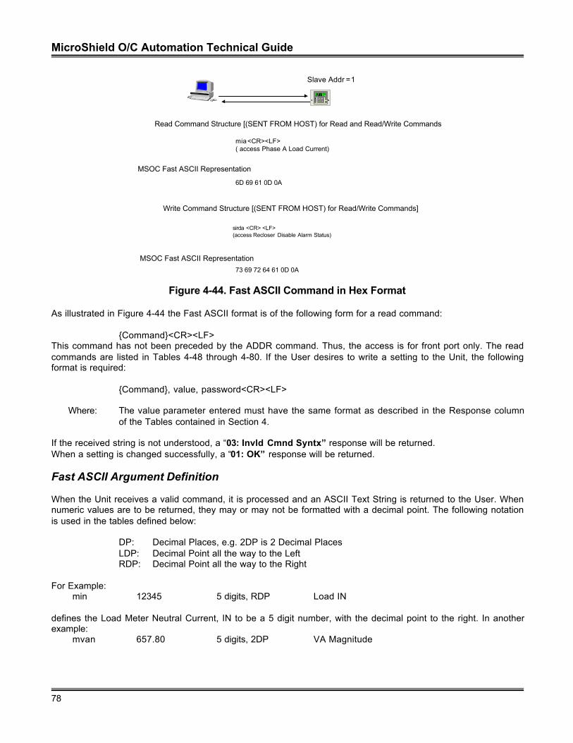
MicroShield O/C Automation Technical Guide
78
Slave Addr =1
E
C
NetworkPartnerV1.0
Read Command Structure [(SENT FROM HOST) for Read and Read/Write Commands
Write Command Structure [(SENT FROM HOST) for Read/Write Commands]
mia <CR><LF>( access Phase A Load Current)
6D 69 61 0D 0A
MSOC Fast ASCII Representation
sirda <CR> <LF>(access Recloser Disable Alarm Status)
MSOC Fast ASCII Representation73 69 72 64 61 0D 0A
Figure 4-44. Fast ASCII Command in Hex Format
As illustrated in Figure 4-44 the Fast ASCII format is of the following form for a read command:
{Command}<CR><LF>This command has not been preceded by the ADDR command. Thus, the access is for front port only. The readcommands are listed in Tables 4-48 through 4-80. If the User desires to write a setting to the Unit, the followingformat is required:
{Command}, value, password<CR><LF>
Where: The value parameter entered must have the same format as described in the Response columnof the Tables contained in Section 4.
If the received string is not understood, a “03: Invld Cmnd Syntx” response will be returned.When a setting is changed successfully, a “01: OK” response will be returned.
Fast ASCII Argument Definition
When the Unit receives a valid command, it is processed and an ASCII Text String is returned to the User. Whennumeric values are to be returned, they may or may not be formatted with a decimal point. The following notationis used in the tables defined below:
DP: Decimal Places, e.g. 2DP is 2 Decimal PlacesLDP: Decimal Point all the way to the LeftRDP: Decimal Point all the way to the Right
For Example:min 12345 5 digits, RDP Load IN
defines the Load Meter Neutral Current, IN to be a 5 digit number, with the decimal point to the right. In anotherexample:
mvan 657.80 5 digits, 2DP VA Magnitude
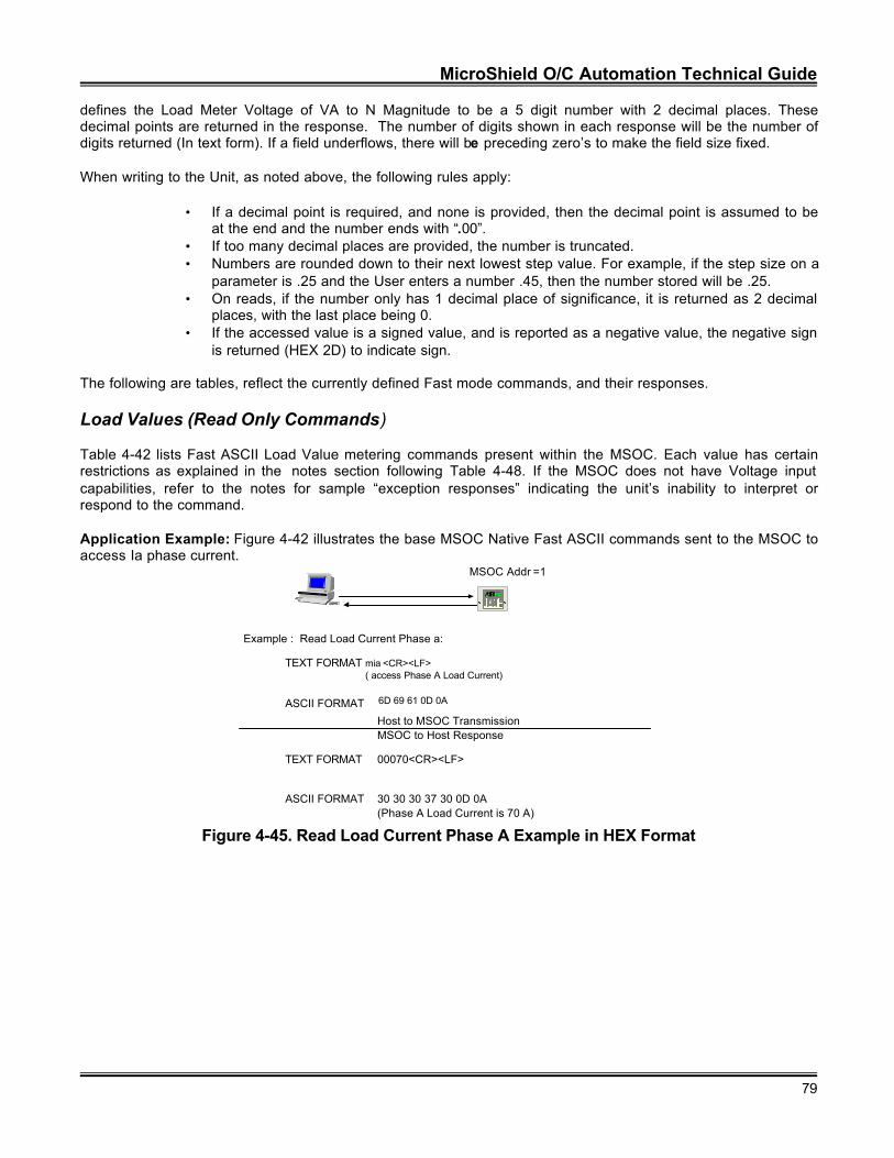
MicroShield O/C Automation Technical Guide
79
defines the Load Meter Voltage of VA to N Magnitude to be a 5 digit number with 2 decimal places. Thesedecimal points are returned in the response. The number of digits shown in each response will be the number ofdigits returned (In text form). If a field underflows, there will be preceding zero’s to make the field size fixed.
When writing to the Unit, as noted above, the following rules apply:
• If a decimal point is required, and none is provided, then the decimal point is assumed to beat the end and the number ends with “.00”.
• If too many decimal places are provided, the number is truncated.• Numbers are rounded down to their next lowest step value. For example, if the step size on a
parameter is .25 and the User enters a number .45, then the number stored will be .25.• On reads, if the number only has 1 decimal place of significance, it is returned as 2 decimal
places, with the last place being 0.• If the accessed value is a signed value, and is reported as a negative value, the negative sign
is returned (HEX 2D) to indicate sign.
The following are tables, reflect the currently defined Fast mode commands, and their responses.
Load Values (Read Only Commands)
Table 4-42 lists Fast ASCII Load Value metering commands present within the MSOC. Each value has certainrestrictions as explained in the notes section following Table 4-48. If the MSOC does not have Voltage inputcapabilities, refer to the notes for sample “exception responses” indicating the unit’s inability to interpret orrespond to the command.
Application Example: Figure 4-42 illustrates the base MSOC Native Fast ASCII commands sent to the MSOC toaccess Ia phase current.
MSOC Addr =1
E
C
Network
PartnerV1.0
Example : Read Load Current Phase a:
mia <CR><LF>( access Phase A Load Current)
6D 69 61 0D 0A
TEXT FORMAT
ASCII FORMAT
Host to MSOC TransmissionMSOC to Host Response
TEXT FORMAT
ASCII FORMAT
00070<CR><LF>
30 30 30 37 30 0D 0A(Phase A Load Current is 70 A)
Figure 4-45. Read Load Current Phase A Example in HEX Format
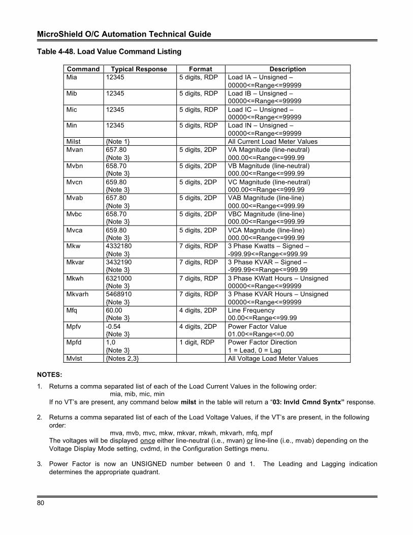
MicroShield O/C Automation Technical Guide
80
Table 4-48. Load Value Command Listing
Command Typical Response Format DescriptionMia 12345 5 digits, RDP Load IA – Unsigned –
00000<=Range<=99999Mib 12345 5 digits, RDP Load IB – Unsigned –
00000<=Range<=99999Mic 12345 5 digits, RDP Load IC – Unsigned –
00000<=Range<=99999Min 12345 5 digits, RDP Load IN – Unsigned –
00000<=Range<=99999Milst {Note 1} All Current Load Meter ValuesMvan 657.80
{Note 3}5 digits, 2DP VA Magnitude (line-neutral)
000.00<=Range<=999.99Mvbn 658.70
{Note 3}5 digits, 2DP VB Magnitude (line-neutral)
000.00<=Range<=999.99Mvcn 659.80
{Note 3}5 digits, 2DP VC Magnitude (line-neutral)
000.00<=Range<=999.99Mvab 657.80
{Note 3}5 digits, 2DP VAB Magnitude (line-line)
000.00<=Range<=999.99Mvbc 658.70
{Note 3}5 digits, 2DP VBC Magnitude (line-line)
000.00<=Range<=999.99Mvca 659.80
{Note 3}5 digits, 2DP VCA Magnitude (line-line)
000.00<=Range<=999.99Mkw 4332180
{Note 3}7 digits, RDP 3 Phase Kwatts – Signed –
-999.99<=Range<=999.99Mkvar 3432190
{Note 3}7 digits, RDP 3 Phase KVAR – Signed –
-999.99<=Range<=999.99Mkwh 6321000
{Note 3}7 digits, RDP 3 Phase KWatt Hours – Unsigned
00000<=Range<=99999Mkvarh 5468910
{Note 3}7 digits, RDP 3 Phase KVAR Hours – Unsigned
00000<=Range<=99999Mfq 60.00
{Note 3}4 digits, 2DP Line Frequency
00.00<=Range<=99.99Mpfv -0.54
{Note 3}4 digits, 2DP Power Factor Value
01.00<=Range<=0.00Mpfd 1,0
{Note 3}1 digit, RDP Power Factor Direction
1 = Lead, 0 = LagMvlst {Notes 2,3} All Voltage Load Meter Values
NOTES:
1. Returns a comma separated list of each of the Load Current Values in the following order:mia, mib, mic, min
If no VT’s are present, any command below milst in the table will return a “03: Invld Cmnd Syntx” response.
2. Returns a comma separated list of each of the Load Voltage Values, if the VT’s are present, in the followingorder:
mva, mvb, mvc, mkw, mkvar, mkwh, mkvarh, mfq, mpfThe voltages will be displayed once either line-neutral (i.e., mvan) or line-line (i.e., mvab) depending on theVoltage Display Mode setting, cvdmd, in the Configuration Settings menu.
3. Power Factor is now an UNSIGNED number between 0 and 1. The Leading and Lagging indicationdetermines the appropriate quadrant.
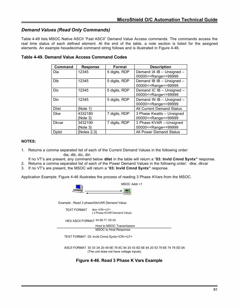
MicroShield O/C Automation Technical Guide
81
Demand Values (Read Only Commands)
Table 4-49 lists MSOC Native ASCII “Fast ASCII” Demand Value Access commands. The commands access thereal time status of each defined element. At the end of the table, a note section is listed for the assignedelements. An example hexadecimal command string follows and is illustrated in Figure 4-46.
Table 4-49. Demand Value Access Command Codes
Command Response Format DescriptionDia 12345 5 digits, RDP Demand IA IB – Unsigned –
00000<=Range<=99999Dib 12345 5 digits, RDP Demand IB IB – Unsigned –
00000<=Range<=99999Dic 12345 5 digits, RDP Demand IC IB – Unsigned –
00000<=Range<=99999Din 12345 5 digits, RDP Demand IN IB – Unsigned –
00000<=Range<=99999Dilst {Note 1} All Current Demand StatusDkw 4332180
{Note 3}7 digits, RDP 3 Phase Kwatts – Unsigned
00000<=Range<=99999Dkvar 3432190
{Note 3}7 digits, RDP 3 Phase KVAR –-Unsigned
00000<=Range<=99999Dplst {Notes 2,3} All Power Demand Status
NOTES:
1. Returns a comma separated list of each of the Current Demand Values in the following order:dia, dib, dic, din
If no VT’s are present, any command below dilst in the table will return a “03: Invld Cmnd Syntx” response.2. Returns a comma separated list of each of the Power Demand Values in the following order: dkw, dkvar3. If no VT’s are present, the MSOC will return a “03: Invld Cmnd Syntx” response.
Application Example: Figure 4-46 illustrates the process of reading 3 Phase KVars from the MSOC.
MSOC Addr =1
E
C
NetworkPartnerV1.0
Example : Read 3 phase KiloVAR Demand Value:
dkw <CR><LF>( 3 Phase KVAR Demand Value)
64 6B 77 0D 0A
TEXT FORMAT
HEX ASCII FORMAT
Host to MSOC TransmissionMSOC to Host Response
TEXT FORMAT
ASCII FORMAT
03: Invld Cmnd Syntx<CR><LF>
30 33 3A 20 49 6E 76 6C 64 20 43 6D 6E 64 20 53 79 6E 74 78 0D 0A(The unit does not have voltage inputs)
Figure 4-46. Read 3 Phase K Vars Example
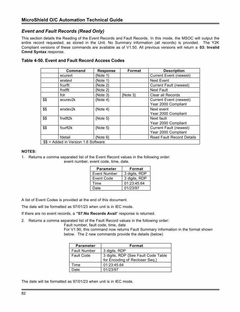
MicroShield O/C Automation Technical Guide
82
Event and Fault Records (Read Only)This section details the Reading of the Event Records and Fault Records. In this mode, the MSOC will output theentire record requested, as stored in the Unit. No Summary information (all records) is provided. The Y2KCompliant versions of these commands are available as of V1.50. All previous versions will return a 03: InvalidCmnd Syntax response.
Table 4-50. Event and Fault Record Access Codes
Command Response Format Descriptionecurevt {Note 1} Current Event (newest)enxtevt {Note 1} Next Eventfcurflt {Note 2} Current Fault (newest)fnxtflt {Note 2} Next Faultfclr {Note 3} {Note 3} Clear all Records
$$ ecurev2k {Note 4} Current Event (newest)Year 2000 Compliant
$$ enxtev2k {Note 4} Next eventYear 2000 Compliant
$$ fnxtft2k {Note 5} Next faultYear 2000 Compliant
$$ fcurft2k {Note 5} Current Fault (newest)Year 2000 Compliant
fdetail {Note 6} Read Fault Record Details$$ = Added in Version 1.6 Software
NOTES:1. Returns a comma separated list of the Event Record values in the following order:
event number, event code, time, date.
Parameter FormatEvent Number 3 digits, RDPEvent Code 3 digits, RDPTime 01:23:45.64Date 01/23/97
A list of Event Codes is provided at the end of this document.
The date will be formatted as 97/01/23 when unit is in IEC mode.
If there are no event records, a “07:No Records Avail” response is returned.
2. Returns a comma separated list of the Fault Record values in the following order:Fault number, fault code, time, dateFor V1.90, this command now returns Fault Summary information in the format shownbelow. The 2 new commands provide the details (below)
Parameter FormatFault Number 3 digits, RDPFault Code 3 digits, RDP {See Fault Code Table
for Encoding of Recloser Seq.}Time 01:23:45.64Date 01/23/97
The date will be formatted as 97/01/23 when unit is in IEC mode.
MicroShield O/C Automation Technical Guide
83
If there are no fault records, a “07:No Records Avail” response is returned.
3. Fclr requires a password as is done when changing settings, e.g.:Fclr, password<CR><LF>
4. Returns a comma separated list of the Event Record values in the following order:event number, event code, time, date.
Parameter FormatEvent Number 3 digits, RDPEvent Code 3 digits, RDPTime 01:23:45.64Date 01/23/97
A list of Event Codes is provided at the end of this document.
The date will be formatted as 97/01/23 when unit is in IEC mode.
If there are no event records, a “07:No Records Avail” response is returned.
5. Returns a comma separated list of the Fault Record values in the following order:Fault number, fault code, time, dateFor V1.90, this command now returns Fault Summary information in the format shownbelow. The 2 new commands provide the details (below)
Parameter FormatFault Number 3 digits, RDPFault Code 3 digits, RDP {See Fault Code Table
for Encoding of Recloser Seq.}Time 01:23:45.64Date 01/23/97
The date will be formatted as 97/01/23 when unit is in IEC mode.
6. In V1.90 it was discovered that the returned string for the Fault information was larger than allowed (exceeded80 characters). Therefore, in order to read ALL fault information, one now needs to execute 2 commands,one to read the Summary information (the existing commands) and another to read the details of the faultrecord. This new command returns the following comma separated list of the Fault Record Details:
Fault number, mia, mib, mic, min, mvan, mvbn, mvcn,Relay Time, Clearing Time (in milliseconds)
The fdetail command relies on the other 4 (the existing 2 current and 2 next) to position the “pointer” of therecord details that it is going to read. For example: fcurflt reads current fault record #4. The fdetail commandwill read the details of fault record #4. The fxntflt command moves to Record #3, and fdetail will read Record#3. And so on through the records stored in the MSOC.
Parameter FormatFault Number 3 digits, RDP {to synchronize with the
Summary information}Current Load Values See table above for encodingVoltage Load Values See table above for encoding, if present
(based on Unit Catalog Number)Relay Time 5 digits, RDPClearing Time 5 digits, RDP
If there are no event records, a “07:No Records Avail” response is returned.
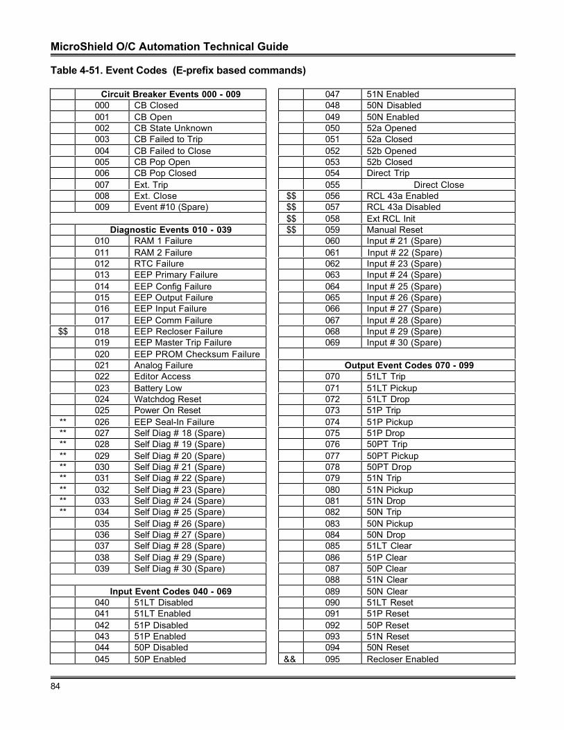
MicroShield O/C Automation Technical Guide
84
Table 4-51. Event Codes (E-prefix based commands)
Circuit Breaker Events 000 - 009 047 51N Enabled000 CB Closed 048 50N Disabled001 CB Open 049 50N Enabled002 CB State Unknown 050 52a Opened003 CB Failed to Trip 051 52a Closed004 CB Failed to Close 052 52b Opened005 CB Pop Open 053 52b Closed006 CB Pop Closed 054 Direct Trip007 Ext. Trip 055 Direct Close008 Ext. Close $$ 056 RCL 43a Enabled009 Event #10 (Spare) $$ 057 RCL 43a Disabled
$$ 058 Ext RCL InitDiagnostic Events 010 - 039 $$ 059 Manual Reset
010 RAM 1 Failure 060 Input # 21 (Spare)011 RAM 2 Failure 061 Input # 22 (Spare)012 RTC Failure 062 Input # 23 (Spare)013 EEP Primary Failure 063 Input # 24 (Spare)014 EEP Config Failure 064 Input # 25 (Spare)015 EEP Output Failure 065 Input # 26 (Spare)016 EEP Input Failure 066 Input # 27 (Spare)017 EEP Comm Failure 067 Input # 28 (Spare)
$$ 018 EEP Recloser Failure 068 Input # 29 (Spare)019 EEP Master Trip Failure 069 Input # 30 (Spare)020 EEP PROM Checksum Failure021 Analog Failure Output Event Codes 070 - 099022 Editor Access 070 51LT Trip023 Battery Low 071 51LT Pickup024 Watchdog Reset 072 51LT Drop025 Power On Reset 073 51P Trip
** 026 EEP Seal-In Failure 074 51P Pickup** 027 Self Diag # 18 (Spare) 075 51P Drop** 028 Self Diag # 19 (Spare) 076 50PT Trip** 029 Self Diag # 20 (Spare) 077 50PT Pickup** 030 Self Diag # 21 (Spare) 078 50PT Drop** 031 Self Diag # 22 (Spare) 079 51N Trip** 032 Self Diag # 23 (Spare) 080 51N Pickup** 033 Self Diag # 24 (Spare) 081 51N Drop** 034 Self Diag # 25 (Spare) 082 50N Trip
035 Self Diag # 26 (Spare) 083 50N Pickup036 Self Diag # 27 (Spare) 084 50N Drop037 Self Diag # 28 (Spare) 085 51LT Clear038 Self Diag # 29 (Spare) 086 51P Clear039 Self Diag # 30 (Spare) 087 50P Clear
088 51N ClearInput Event Codes 040 - 069 089 50N Clear
040 51LT Disabled 090 51LT Reset041 51LT Enabled 091 51P Reset042 51P Disabled 092 50P Reset043 51P Enabled 093 51N Reset044 50P Disabled 094 50N Reset045 50P Enabled && 095 Recloser Enabled
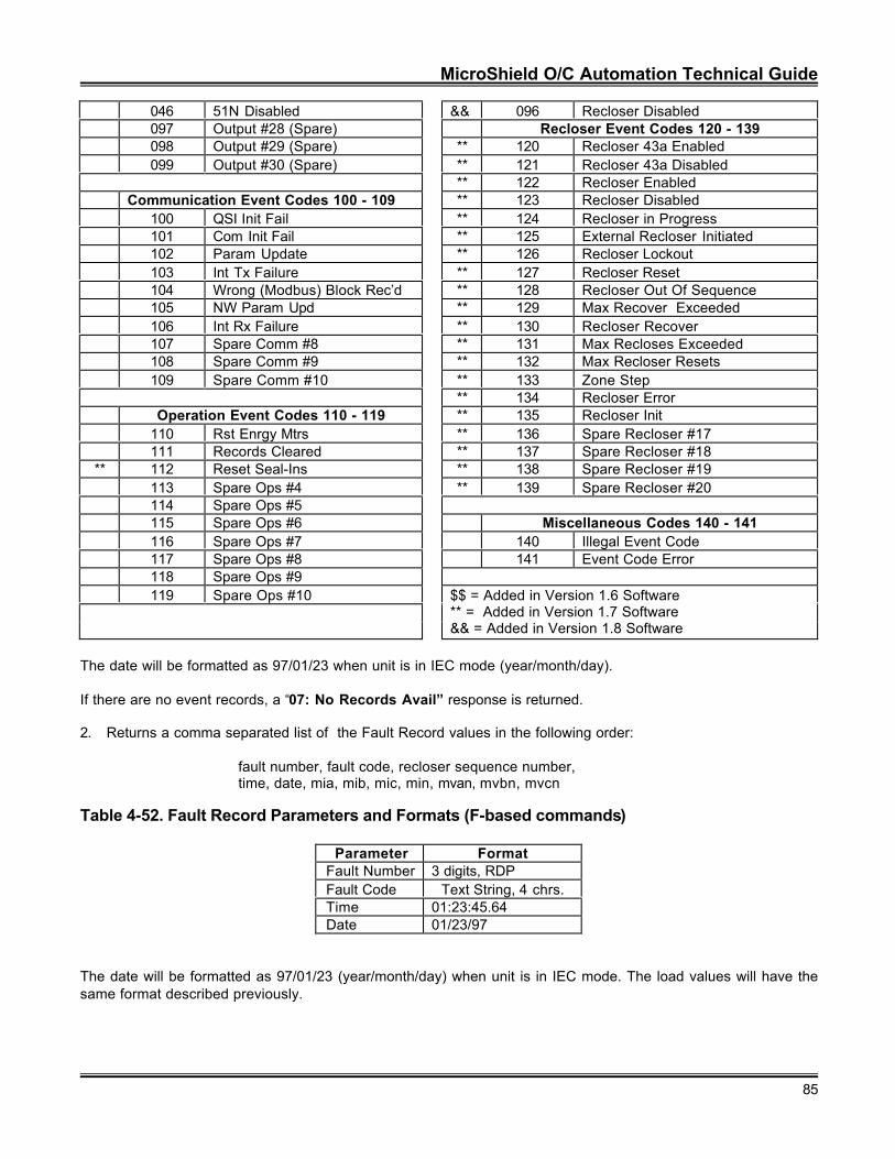
MicroShield O/C Automation Technical Guide
85
046 51N Disabled && 096 Recloser Disabled097 Output #28 (Spare) Recloser Event Codes 120 - 139098 Output #29 (Spare) ** 120 Recloser 43a Enabled099 Output #30 (Spare) ** 121 Recloser 43a Disabled
** 122 Recloser EnabledCommunication Event Codes 100 - 109 ** 123 Recloser Disabled
100 QSI Init Fail ** 124 Recloser in Progress101 Com Init Fail ** 125 External Recloser Initiated102 Param Update ** 126 Recloser Lockout103 Int Tx Failure ** 127 Recloser Reset104 Wrong (Modbus) Block Rec’d ** 128 Recloser Out Of Sequence105 NW Param Upd ** 129 Max Recover Exceeded106 Int Rx Failure ** 130 Recloser Recover107 Spare Comm #8 ** 131 Max Recloses Exceeded108 Spare Comm #9 ** 132 Max Recloser Resets109 Spare Comm #10 ** 133 Zone Step
** 134 Recloser ErrorOperation Event Codes 110 - 119 ** 135 Recloser Init
110 Rst Enrgy Mtrs ** 136 Spare Recloser #17111 Records Cleared ** 137 Spare Recloser #18
** 112 Reset Seal-Ins ** 138 Spare Recloser #19113 Spare Ops #4 ** 139 Spare Recloser #20114 Spare Ops #5115 Spare Ops #6 Miscellaneous Codes 140 - 141116 Spare Ops #7 140 Illegal Event Code117 Spare Ops #8 141 Event Code Error118 Spare Ops #9119 Spare Ops #10 $$ = Added in Version 1.6 Software
** = Added in Version 1.7 Software&& = Added in Version 1.8 Software
The date will be formatted as 97/01/23 when unit is in IEC mode (year/month/day).
If there are no event records, a “07: No Records Avail” response is returned.
2. Returns a comma separated list of the Fault Record values in the following order:
fault number, fault code, recloser sequence number,time, date, mia, mib, mic, min, mvan, mvbn, mvcn
Table 4-52. Fault Record Parameters and Formats (F-based commands)
Parameter Format Fault Number 3 digits, RDP Fault Code Text String, 4 chrs. Time 01:23:45.64 Date 01/23/97
The date will be formatted as 97/01/23 (year/month/day) when unit is in IEC mode. The load values will have thesame format described previously.
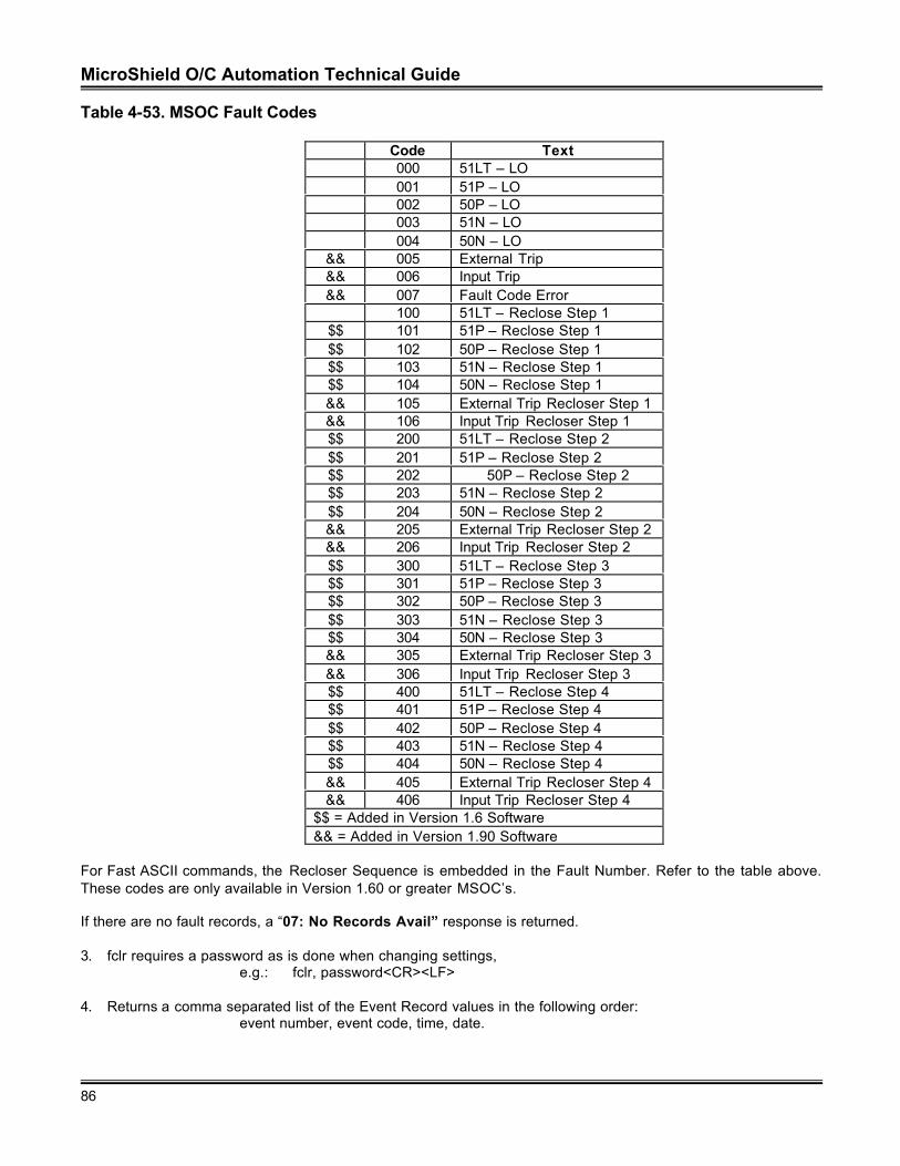
MicroShield O/C Automation Technical Guide
86
Table 4-53. MSOC Fault Codes
Code Text000 51LT – LO001 51P – LO002 50P – LO003 51N – LO004 50N – LO
&& 005 External Trip&& 006 Input Trip&& 007 Fault Code Error
100 51LT – Reclose Step 1$$ 101 51P – Reclose Step 1$$ 102 50P – Reclose Step 1$$ 103 51N – Reclose Step 1$$ 104 50N – Reclose Step 1&& 105 External Trip Recloser Step 1&& 106 Input Trip Recloser Step 1$$ 200 51LT – Reclose Step 2$$ 201 51P – Reclose Step 2$$ 202 50P – Reclose Step 2$$ 203 51N – Reclose Step 2$$ 204 50N – Reclose Step 2&& 205 External Trip Recloser Step 2&& 206 Input Trip Recloser Step 2$$ 300 51LT – Reclose Step 3$$ 301 51P – Reclose Step 3$$ 302 50P – Reclose Step 3$$ 303 51N – Reclose Step 3$$ 304 50N – Reclose Step 3&& 305 External Trip Recloser Step 3&& 306 Input Trip Recloser Step 3$$ 400 51LT – Reclose Step 4$$ 401 51P – Reclose Step 4$$ 402 50P – Reclose Step 4$$ 403 51N – Reclose Step 4$$ 404 50N – Reclose Step 4&& 405 External Trip Recloser Step 4&& 406 Input Trip Recloser Step 4
$$ = Added in Version 1.6 Software&& = Added in Version 1.90 Software
For Fast ASCII commands, the Recloser Sequence is embedded in the Fault Number. Refer to the table above.These codes are only available in Version 1.60 or greater MSOC’s.
If there are no fault records, a “07: No Records Avail” response is returned.
3. fclr requires a password as is done when changing settings,e.g.: fclr, password<CR><LF>
4. Returns a comma separated list of the Event Record values in the following order:event number, event code, time, date.
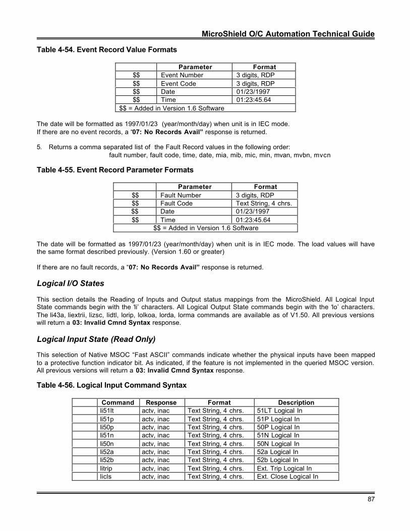
MicroShield O/C Automation Technical Guide
87
Table 4-54. Event Record Value Formats
Parameter Format$$ Event Number 3 digits, RDP$$ Event Code 3 digits, RDP$$ Date 01/23/1997$$ Time 01:23:45.64
$$ = Added in Version 1.6 Software
The date will be formatted as 1997/01/23 (year/month/day) when unit is in IEC mode.If there are no event records, a “07: No Records Avail” response is returned.
5. Returns a comma separated list of the Fault Record values in the following order:fault number, fault code, time, date, mia, mib, mic, min, mvan, mvbn, mvcn
Table 4-55. Event Record Parameter Formats
Parameter Format $$ Fault Number 3 digits, RDP $$ Fault Code Text String, 4 chrs.$$ Date 01/23/1997 $$ Time 01:23:45.64
$$ = Added in Version 1.6 Software
The date will be formatted as 1997/01/23 (year/month/day) when unit is in IEC mode. The load values will havethe same format described previously. (Version 1.60 or greater)
If there are no fault records, a “07: No Records Avail” response is returned.
Logical I/O States
This section details the Reading of Inputs and Output status mappings from the MicroShield. All Logical InputState commands begin with the ‘li’ characters. All Logical Output State commands begin with the ‘lo’ characters.The li43a, liextrii, lizsc, lidtl, lorip, lolkoa, lorda, lorma commands are available as of V1.50. All previous versionswill return a 03: Invalid Cmnd Syntax response.
Logical Input State (Read Only)
This selection of Native MSOC “Fast ASCII” commands indicate whether the physical inputs have been mappedto a protective function indicator bit. As indicated, if the feature is not implemented in the queried MSOC version.All previous versions will return a 03: Invalid Cmnd Syntax response.
Table 4-56. Logical Input Command Syntax
Command Response Format Descriptionli51lt actv, inac Text String, 4 chrs. 51LT Logical Inli51p actv, inac Text String, 4 chrs. 51P Logical Inli50p actv, inac Text String, 4 chrs. 50P Logical Inli51n actv, inac Text String, 4 chrs. 51N Logical Inli50n actv, inac Text String, 4 chrs. 50N Logical Inli52a actv, inac Text String, 4 chrs. 52a Logical Inli52b actv, inac Text String, 4 chrs. 52b Logical Inlitrip actv, inac Text String, 4 chrs. Ext. Trip Logical Inlicls actv, inac Text String, 4 chrs. Ext. Close Logical In
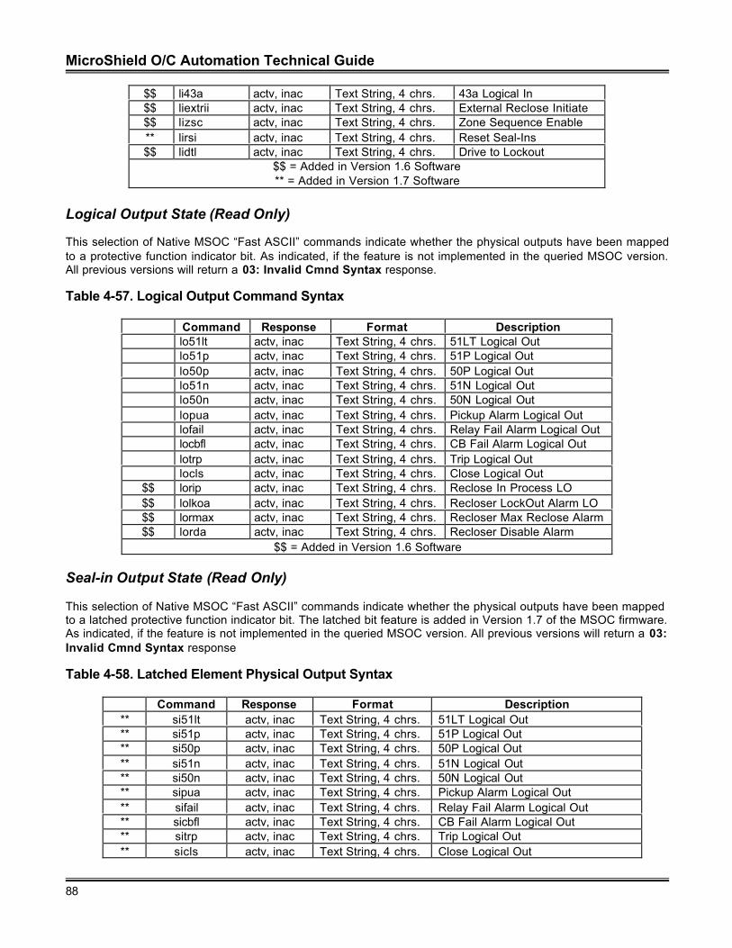
MicroShield O/C Automation Technical Guide
88
$$ li43a actv, inac Text String, 4 chrs. 43a Logical In$$ liextrii actv, inac Text String, 4 chrs. External Reclose Initiate$$ lizsc actv, inac Text String, 4 chrs. Zone Sequence Enable** lirsi actv, inac Text String, 4 chrs. Reset Seal-Ins$$ lidtl actv, inac Text String, 4 chrs. Drive to Lockout
$$ = Added in Version 1.6 Software** = Added in Version 1.7 Software
Logical Output State (Read Only)
This selection of Native MSOC “Fast ASCII” commands indicate whether the physical outputs have been mappedto a protective function indicator bit. As indicated, if the feature is not implemented in the queried MSOC version.All previous versions will return a 03: Invalid Cmnd Syntax response.
Table 4-57. Logical Output Command Syntax
Command Response Format Descriptionlo51lt actv, inac Text String, 4 chrs. 51LT Logical Outlo51p actv, inac Text String, 4 chrs. 51P Logical Outlo50p actv, inac Text String, 4 chrs. 50P Logical Outlo51n actv, inac Text String, 4 chrs. 51N Logical Outlo50n actv, inac Text String, 4 chrs. 50N Logical Outlopua actv, inac Text String, 4 chrs. Pickup Alarm Logical Outlofail actv, inac Text String, 4 chrs. Relay Fail Alarm Logical Outlocbfl actv, inac Text String, 4 chrs. CB Fail Alarm Logical Outlotrp actv, inac Text String, 4 chrs. Trip Logical Outlocls actv, inac Text String, 4 chrs. Close Logical Out
$$ lorip actv, inac Text String, 4 chrs. Reclose In Process LO$$ lolkoa actv, inac Text String, 4 chrs. Recloser LockOut Alarm LO$$ lormax actv, inac Text String, 4 chrs. Recloser Max Reclose Alarm$$ lorda actv, inac Text String, 4 chrs. Recloser Disable Alarm
$$ = Added in Version 1.6 Software
Seal-in Output State (Read Only)
This selection of Native MSOC “Fast ASCII” commands indicate whether the physical outputs have been mappedto a latched protective function indicator bit. The latched bit feature is added in Version 1.7 of the MSOC firmware.As indicated, if the feature is not implemented in the queried MSOC version. All previous versions will return a 03:Invalid Cmnd Syntax response
Table 4-58. Latched Element Physical Output Syntax
Command Response Format Description** si51lt actv, inac Text String, 4 chrs. 51LT Logical Out** si51p actv, inac Text String, 4 chrs. 51P Logical Out** si50p actv, inac Text String, 4 chrs. 50P Logical Out** si51n actv, inac Text String, 4 chrs. 51N Logical Out** si50n actv, inac Text String, 4 chrs. 50N Logical Out** sipua actv, inac Text String, 4 chrs. Pickup Alarm Logical Out** sifail actv, inac Text String, 4 chrs. Relay Fail Alarm Logical Out** sicbfl actv, inac Text String, 4 chrs. CB Fail Alarm Logical Out** sitrp actv, inac Text String, 4 chrs. Trip Logical Out** sicls actv, inac Text String, 4 chrs. Close Logical Out
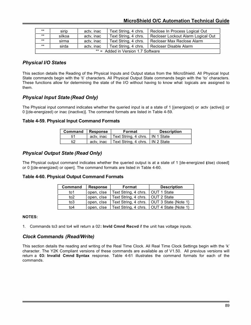
MicroShield O/C Automation Technical Guide
89
** sirip actv, inac Text String, 4 chrs. Reclose In Process Logical Out** silkoa actv, inac Text String, 4 chrs. Recloser Lockout Alarm Logical Out** sirma actv, inac Text String, 4 chrs. Recloser Max Reclose Alarm** sirda actv, inac Text String, 4 chrs. Recloser Disable Alarm
** = Added in Version 1.7 Software
Physical I/O States
This section details the Reading of the Physical Inputs and Output status from the MicroShield. All Physical InputState commands begin with the ‘ti’ characters. All Physical Output State commands begin with the ‘to’ characters.These functions allow for determining the state of the I/O without having to know what logicals are assigned tothem.
Physical Input State (Read Only)
The Physical input command indicates whether the queried input is at a state of 1 [(energized) or actv (active)] or0 [(de-energized) or inac (inactive)]. The command formats are listed in Table 4-59.
Table 4-59. Physical Input Command Formats
Command Response Format Descriptionti1 actv, inac Text String, 4 chrs. IN 1 Stateti2 actv, inac Text String, 4 chrs. IN 2 State
Physical Output State (Read Only)
The Physical output command indicates whether the queried output is at a state of 1 [de-energized (clse) closed]or 0 [(de-energized) or open]. The command formats are listed in Table 4-60.
Table 4-60. Physical Output Command Formats
Command Response Format Descriptionto1 open, clse Text String, 4 chrs. OUT 1 Stateto2 open, clse Text String, 4 chrs. OUT 2 Stateto3 open, clse Text String, 4 chrs. OUT 3 State {Note 1}to4 open, clse Text String, 4 chrs. OUT 4 State {Note 1}
NOTES:
1. Commands to3 and to4 will return a 02: Invld Cmnd Recvd if the unit has voltage inputs.
Clock Commands (Read/Write)
This section details the reading and writing of the Real Time Clock. All Real Time Clock Settings begin with the ‘k’character. The Y2K Compliant versions of these commands are available as of V1.50. All previous versions willreturn a 03: Invalid Cmnd Syntax response. Table 4-61 illustrates the command formats for each of thecommands.
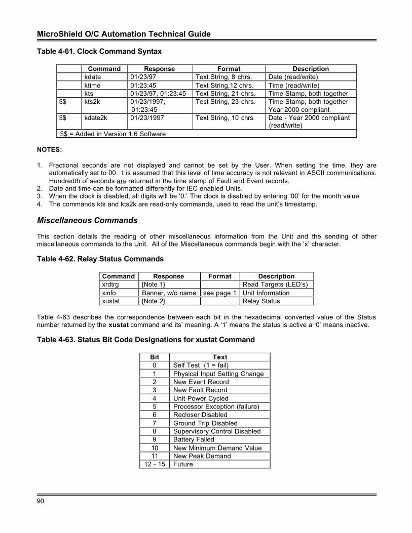
MicroShield O/C Automation Technical Guide
90
Table 4-61. Clock Command Syntax
Command Response Format Descriptionkdate 01/23/97 Text String, 8 chrs. Date (read/write)ktime 01:23:45 Text String,12 chrs. Time (read/write)kts 01/23/97, 01:23:45 Text String, 21 chrs. Time Stamp, both together
$$ kts2k 01/23/1997,01:23:45
Test String, 23 chrs. Time Stamp, both togetherYear 2000 compliant
$$ kdate2k 01/23/1997 Text String, 10 chrs Date - Year 2000 compliant(read/write)
$$ = Added in Version 1.6 Software
NOTES:
1. Fractional seconds are not displayed and cannot be set by the User. When setting the time, they areautomatically set to 00. t is assumed that this level of time accuracy is not relevant in ASCII communications.Hundredth of seconds are returned in the time stamp of Fault and Event records.
2. Date and time can be formatted differently for IEC enabled Units.3. When the clock is disabled, all digits will be ‘0.’ The clock is disabled by entering ‘00’ for the month value.4. The commands kts and kts2k are read-only commands, used to read the unit’s timestamp.
Miscellaneous Commands
This section details the reading of other miscellaneous information from the Unit and the sending of othermiscellaneous commands to the Unit. All of the Miscellaneous commands begin with the ‘x’ character.
Table 4-62. Relay Status Commands
Command Response Format Descriptionxrdtrg {Note 1} Read Targets (LED’s)xinfo Banner, w/o name see page 1 Unit Informationxustat {Note 2} Relay Status
Table 4-63 describes the correspondence between each bit in the hexadecimal converted value of the Statusnumber returned by the xustat command and its’ meaning. A ‘1’ means the status is active a ‘0’ means inactive.
Table 4-63. Status Bit Code Designations for xustat Command
Bit Text0 Self Test (1 = fail)1 Physical Input Setting Change2 New Event Record3 New Fault Record4 Unit Power Cycled5 Processor Exception (failure)6 Recloser Disabled7 Ground Trip Disabled8 Supervisory Control Disabled9 Battery Failed10 New Minimum Demand Value11 New Peak Demand
12 - 15 Future
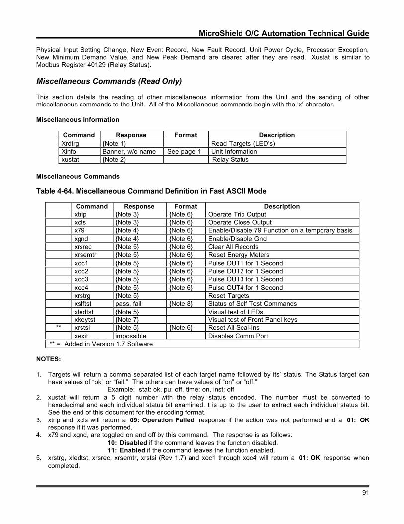
MicroShield O/C Automation Technical Guide
91
Physical Input Setting Change, New Event Record, New Fault Record, Unit Power Cycle, Processor Exception,New Minimum Demand Value, and New Peak Demand are cleared after they are read. Xustat is similar toModbus Register 40129 (Relay Status).
Miscellaneous Commands (Read Only)
This section details the reading of other miscellaneous information from the Unit and the sending of othermiscellaneous commands to the Unit. All of the Miscellaneous commands begin with the ‘x’ character.
Miscellaneous Information
Command Response Format DescriptionXrdtrg {Note 1} Read Targets (LED’s)Xinfo Banner, w/o name See page 1 Unit Informationxustat {Note 2} Relay Status
Miscellaneous Commands
Table 4-64. Miscellaneous Command Definition in Fast ASCII Mode
Command Response Format Descriptionxtrip {Note 3} {Note 6} Operate Trip Outputxcls {Note 3} {Note 6} Operate Close Outputx79 {Note 4} {Note 6} Enable/Disable 79 Function on a temporary basisxgnd {Note 4} {Note 6} Enable/Disable Gndxrsrec {Note 5} {Note 6} Clear All Recordsxrsemtr {Note 5} {Note 6} Reset Energy Metersxoc1 {Note 5} {Note 6} Pulse OUT1 for 1 Secondxoc2 {Note 5} {Note 6} Pulse OUT2 for 1 Secondxoc3 {Note 5} {Note 6} Pulse OUT3 for 1 Secondxoc4 {Note 5} {Note 6} Pulse OUT4 for 1 Secondxrstrg {Note 5} Reset Targetsxslftst pass, fail {Note 8} Status of Self Test Commandsxledtst {Note 5} Visual test of LEDsxkeytst {Note 7} Visual test of Front Panel keys
** xrstsi {Note 5} {Note 6} Reset All Seal-Insxexit impossible Disables Comm Port
** = Added in Version 1.7 Software
NOTES:
1. Targets will return a comma separated list of each target name followed by its’ status. The Status target canhave values of “ok” or “fail.” The others can have values of “on” or “off.”
Example: stat: ok, pu: off, time: on, inst: off2. xustat will return a 5 digit number with the relay status encoded. The number must be converted to
hexadecimal and each individual status bit examined. t is up to the user to extract each individual status bit.See the end of this document for the encoding format.
3. xtrip and xcls will return a 09: Operation Failed response if the action was not performed and a 01: OKresponse if it was performed.
4. x79 and xgnd, are toggled on and off by this command. The response is as follows:10: Disabled if the command leaves the function disabled.11: Enabled if the command leaves the function enabled.
5. xrstrg, xledtst, xrsrec, xrsemtr, xrstsi (Rev 1.7) and xoc1 through xoc4 will return a 01: OK response whencompleted.
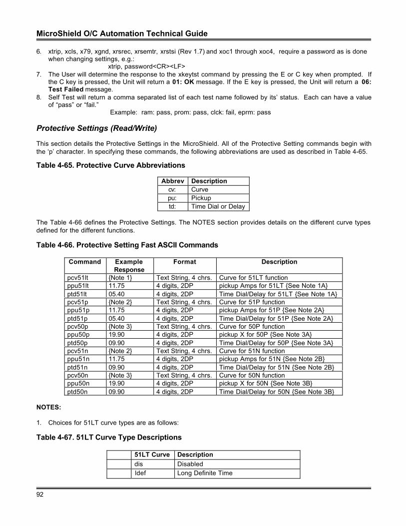
MicroShield O/C Automation Technical Guide
92
6. xtrip, xcls, x79, xgnd, xrsrec, xrsemtr, xrstsi (Rev 1.7) and xoc1 through xoc4, require a password as is donewhen changing settings, e.g.:
xtrip, password<CR><LF>7. The User will determine the response to the xkeytst command by pressing the E or C key when prompted. If
the C key is pressed, the Unit will return a 01: OK message. If the E key is pressed, the Unit will return a 06:Test Failed message.
8. Self Test will return a comma separated list of each test name followed by its’ status. Each can have a valueof “pass” or “fail.”
Example: ram: pass, prom: pass, clck: fail, eprm: pass
Protective Settings (Read/Write)
This section details the Protective Settings in the MicroShield. All of the Protective Setting commands begin withthe ‘p’ character. In specifying these commands, the following abbreviations are used as described in Table 4-65.
Table 4-65. Protective Curve Abbreviations
Abbrev Descriptioncv: Curvepu: Pickuptd: Time Dial or Delay
The Table 4-66 defines the Protective Settings. The NOTES section provides details on the different curve typesdefined for the different functions.
Table 4-66. Protective Setting Fast ASCII Commands
Command ExampleResponse
Format Description
pcv51lt {Note 1} Text String, 4 chrs. Curve for 51LT functionppu51lt 11.75 4 digits, 2DP pickup Amps for 51LT {See Note 1A}ptd51lt 05.40 4 digits, 2DP Time Dial/Delay for 51LT {See Note 1A}pcv51p {Note 2} Text String, 4 chrs. Curve for 51P functionppu51p 11.75 4 digits, 2DP pickup Amps for 51P {See Note 2A}ptd51p 05.40 4 digits, 2DP Time Dial/Delay for 51P {See Note 2A}pcv50p {Note 3} Text String, 4 chrs. Curve for 50P functionppu50p 19.90 4 digits, 2DP pickup X for 50P {See Note 3A}ptd50p 09.90 4 digits, 2DP Time Dial/Delay for 50P {See Note 3A}pcv51n {Note 2} Text String, 4 chrs. Curve for 51N functionppu51n 11.75 4 digits, 2DP pickup Amps for 51N {See Note 2B}ptd51n 09.90 4 digits, 2DP Time Dial/Delay for 51N {See Note 2B}pcv50n {Note 3} Text String, 4 chrs. Curve for 50N functionppu50n 19.90 4 digits, 2DP pickup X for 50N {See Note 3B}ptd50n 09.90 4 digits, 2DP Time Dial/Delay for 50N {See Note 3B}
NOTES:
1. Choices for 51LT curve types are as follows:
Table 4-67. 51LT Curve Type Descriptions
51LT Curve Descriptiondis Disabledldef Long Definite Time
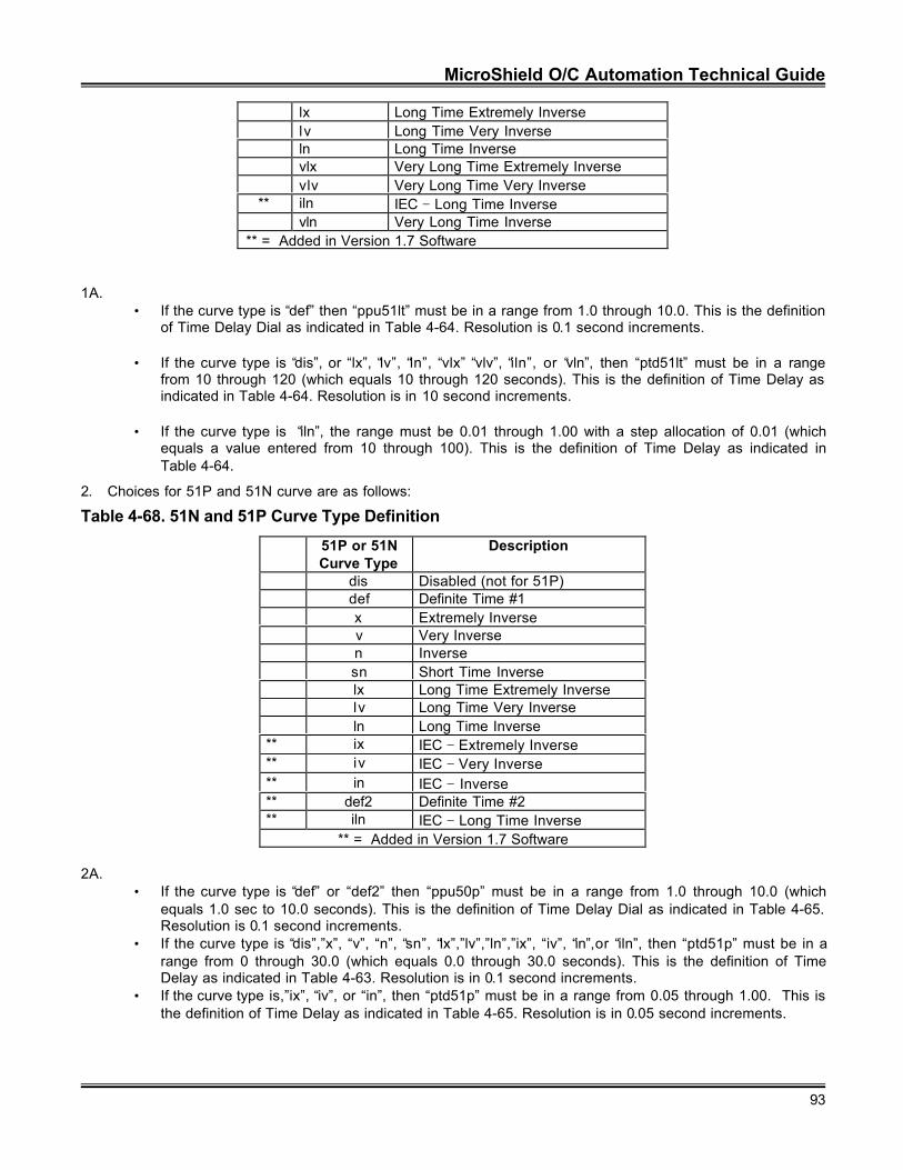
MicroShield O/C Automation Technical Guide
93
lx Long Time Extremely Inverselv Long Time Very Inverseln Long Time Inversevlx Very Long Time Extremely Inversevlv Very Long Time Very Inverse
** iln IEC − Long Time Inversevln Very Long Time Inverse
** = Added in Version 1.7 Software
1A.• If the curve type is “def” then “ppu51lt” must be in a range from 1.0 through 10.0. This is the definition
of Time Delay Dial as indicated in Table 4-64. Resolution is 0.1 second increments.
• If the curve type is “dis”, or “lx”, “lv”, “ln”, “vlx” “vlv”, “iln”, or “vln”, then “ptd51lt” must be in a rangefrom 10 through 120 (which equals 10 through 120 seconds). This is the definition of Time Delay asindicated in Table 4-64. Resolution is in 10 second increments.
• If the curve type is “iln”, the range must be 0.01 through 1.00 with a step allocation of 0.01 (whichequals a value entered from 10 through 100). This is the definition of Time Delay as indicated inTable 4-64.
2. Choices for 51P and 51N curve are as follows:
Table 4-68. 51N and 51P Curve Type Definition
51P or 51NCurve Type
Description
dis Disabled (not for 51P)def Definite Time #1x Extremely Inversev Very Inversen Inversesn Short Time Inverselx Long Time Extremely Inverselv Long Time Very Inverseln Long Time Inverse
** ix IEC − Extremely Inverse** iv IEC − Very Inverse** in IEC − Inverse** def2 Definite Time #2** iln IEC − Long Time Inverse
** = Added in Version 1.7 Software
2A.• If the curve type is “def” or “def2” then “ppu50p” must be in a range from 1.0 through 10.0 (which
equals 1.0 sec to 10.0 seconds). This is the definition of Time Delay Dial as indicated in Table 4-65.Resolution is 0.1 second increments.
• If the curve type is “dis”,”x”, “v”, “n”, “sn”, “lx”,”lv”,”ln”,”ix”, “iv”, “in”,or “iln”, then “ptd51p” must be in arange from 0 through 30.0 (which equals 0.0 through 30.0 seconds). This is the definition of TimeDelay as indicated in Table 4-63. Resolution is in 0.1 second increments.
• If the curve type is,”ix”, “iv”, or “in”, then “ptd51p” must be in a range from 0.05 through 1.00. This isthe definition of Time Delay as indicated in Table 4-65. Resolution is in 0.05 second increments.
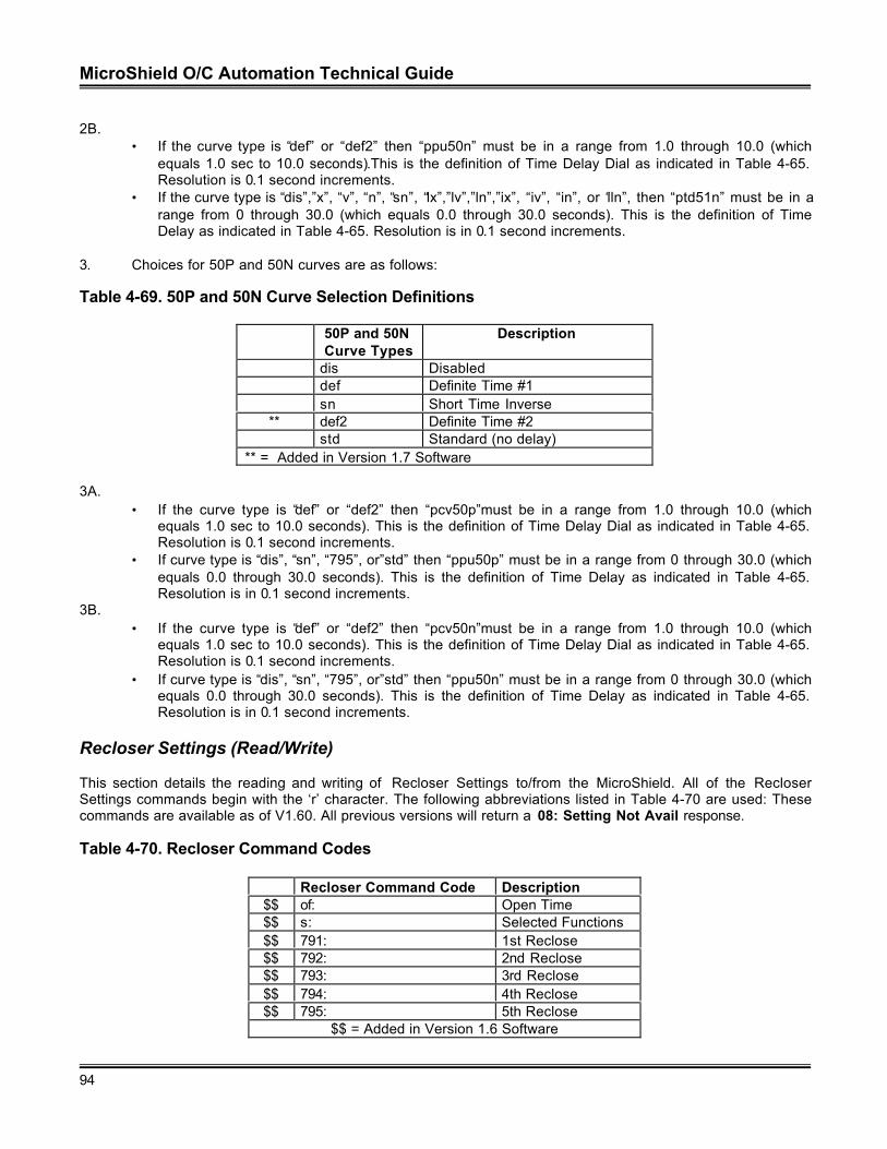
MicroShield O/C Automation Technical Guide
94
2B.• If the curve type is “def” or “def2” then “ppu50n” must be in a range from 1.0 through 10.0 (which
equals 1.0 sec to 10.0 seconds).This is the definition of Time Delay Dial as indicated in Table 4-65.Resolution is 0.1 second increments.
• If the curve type is “dis”,”x”, “v”, “n”, “sn”, “lx”,”lv”,”ln”,”ix”, “iv”, “in”, or “iln”, then “ptd51n” must be in arange from 0 through 30.0 (which equals 0.0 through 30.0 seconds). This is the definition of TimeDelay as indicated in Table 4-65. Resolution is in 0.1 second increments.
3. Choices for 50P and 50N curves are as follows:
Table 4-69. 50P and 50N Curve Selection Definitions
50P and 50NCurve Types
Description
dis Disableddef Definite Time #1sn Short Time Inverse
** def2 Definite Time #2std Standard (no delay)
** = Added in Version 1.7 Software
3A.• If the curve type is “def” or “def2” then “pcv50p”must be in a range from 1.0 through 10.0 (which
equals 1.0 sec to 10.0 seconds). This is the definition of Time Delay Dial as indicated in Table 4-65.Resolution is 0.1 second increments.
• If curve type is “dis”, “sn”, “795”, or”std” then “ppu50p” must be in a range from 0 through 30.0 (whichequals 0.0 through 30.0 seconds). This is the definition of Time Delay as indicated in Table 4-65.Resolution is in 0.1 second increments.
3B.• If the curve type is “def” or “def2” then “pcv50n”must be in a range from 1.0 through 10.0 (which
equals 1.0 sec to 10.0 seconds). This is the definition of Time Delay Dial as indicated in Table 4-65.Resolution is 0.1 second increments.
• If curve type is “dis”, “sn”, “795”, or”std” then “ppu50n” must be in a range from 0 through 30.0 (whichequals 0.0 through 30.0 seconds). This is the definition of Time Delay as indicated in Table 4-65.Resolution is in 0.1 second increments.
Recloser Settings (Read/Write)
This section details the reading and writing of Recloser Settings to/from the MicroShield. All of the RecloserSettings commands begin with the ‘r’ character. The following abbreviations listed in Table 4-70 are used: Thesecommands are available as of V1.60. All previous versions will return a 08: Setting Not Avail response.
Table 4-70. Recloser Command Codes
Recloser Command Code Description$$ of: Open Time$$ s: Selected Functions$$ 791: 1st Reclose$$ 792: 2nd Reclose$$ 793: 3rd Reclose$$ 794: 4th Reclose$$ 795: 5th Reclose
$$ = Added in Version 1.6 Software
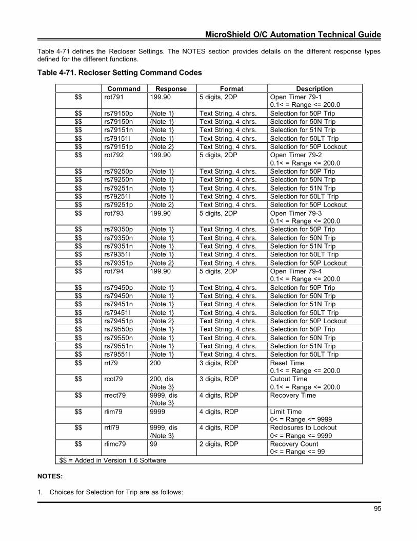
MicroShield O/C Automation Technical Guide
95
Table 4-71 defines the Recloser Settings. The NOTES section provides details on the different response typesdefined for the different functions.
Table 4-71. Recloser Setting Command Codes
Command Response Format Description$$ rot791 199.90 5 digits, 2DP Open Timer 79-1
0.1< = Range <= 200.0$$ rs79150p {Note 1} Text String, 4 chrs. Selection for 50P Trip$$ rs79150n {Note 1} Text String, 4 chrs. Selection for 50N Trip$$ rs79151n {Note 1} Text String, 4 chrs. Selection for 51N Trip$$ rs79151l {Note 1} Text String, 4 chrs. Selection for 50LT Trip$$ rs79151p {Note 2} Text String, 4 chrs. Selection for 50P Lockout$$ rot792 199.90 5 digits, 2DP Open Timer 79-2
0.1< = Range <= 200.0$$ rs79250p {Note 1} Text String, 4 chrs. Selection for 50P Trip$$ rs79250n {Note 1} Text String, 4 chrs. Selection for 50N Trip$$ rs79251n {Note 1} Text String, 4 chrs. Selection for 51N Trip$$ rs79251l {Note 1} Text String, 4 chrs. Selection for 50LT Trip$$ rs79251p {Note 2} Text String, 4 chrs. Selection for 50P Lockout$$ rot793 199.90 5 digits, 2DP Open Timer 79-3
0.1< = Range <= 200.0$$ rs79350p {Note 1} Text String, 4 chrs. Selection for 50P Trip$$ rs79350n {Note 1} Text String, 4 chrs. Selection for 50N Trip$$ rs79351n {Note 1} Text String, 4 chrs. Selection for 51N Trip$$ rs79351l {Note 1} Text String, 4 chrs. Selection for 50LT Trip$$ rs79351p {Note 2} Text String, 4 chrs. Selection for 50P Lockout$$ rot794 199.90 5 digits, 2DP Open Timer 79-4
0.1< = Range <= 200.0$$ rs79450p {Note 1} Text String, 4 chrs. Selection for 50P Trip$$ rs79450n {Note 1} Text String, 4 chrs. Selection for 50N Trip$$ rs79451n {Note 1} Text String, 4 chrs. Selection for 51N Trip$$ rs79451l {Note 1} Text String, 4 chrs. Selection for 50LT Trip$$ rs79451p {Note 2} Text String, 4 chrs. Selection for 50P Lockout$$ rs79550p {Note 1} Text String, 4 chrs. Selection for 50P Trip$$ rs79550n {Note 1} Text String, 4 chrs. Selection for 50N Trip$$ rs79551n {Note 1} Text String, 4 chrs. Selection for 51N Trip$$ rs79551l {Note 1} Text String, 4 chrs. Selection for 50LT Trip$$ rrt79 200 3 digits, RDP Reset Time
0.1< = Range <= 200.0$$ rcot79 200, dis
{Note 3}3 digits, RDP Cutout Time
0.1< = Range <= 200.0$$ rrect79 9999, dis
{Note 3}4 digits, RDP Recovery Time
$$ rlim79 9999 4 digits, RDP Limit Time0< = Range <= 9999
$$ rrtl79 9999, dis{Note 3}
4 digits, RDP Reclosures to Lockout0< = Range <= 9999
$$ rlimc79 99 2 digits, RDP Recovery Count0< = Range <= 99
$$ = Added in Version 1.6 Software
NOTES:
1. Choices for Selection for Trip are as follows:
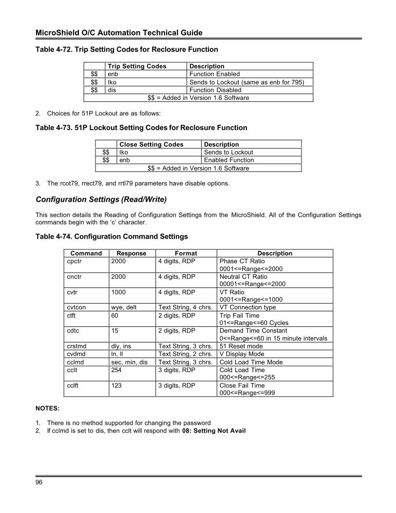
MicroShield O/C Automation Technical Guide
96
Table 4-72. Trip Setting Codes for Reclosure Function
Trip Setting Codes Description$$ enb Function Enabled$$ lko Sends to Lockout (same as enb for 795)$$ dis Function Disabled
$$ = Added in Version 1.6 Software
2. Choices for 51P Lockout are as follows:
Table 4-73. 51P Lockout Setting Codes for Reclosure Function
Close Setting Codes Description$$ lko Sends to Lockout$$ enb Enabled Function
$$ = Added in Version 1.6 Software
3. The rcot79, rrect79, and rrtl79 parameters have disable options.
Configuration Settings (Read/Write)
This section details the Reading of Configuration Settings from the MicroShield. All of the Configuration Settingscommands begin with the ‘c’ character.
Table 4-74. Configuration Command Settings
Command Response Format Descriptioncpctr 2000 4 digits, RDP Phase CT Ratio
0001<=Range<=2000cnctr 2000 4 digits, RDP Neutral CT Ratio
00001<=Range<=2000cvtr 1000 4 digits, RDP VT Ratio
0001<=Range<=1000cvtcon wye, delt Text String, 4 chrs. VT Connection typectft 60 2 digits, RDP Trip Fail Time
01<=Range<=60 Cyclescdtc 15 2 digits, RDP Demand Time Constant
0<=Range<=60 in 15 minute intervalscrstmd dly, ins Text String, 3 chrs. 51 Reset modecvdmd ln, ll Text String, 2 chrs. V Display Modecclmd sec, min, dis Text String, 3 chrs. Cold Load Time Modecclt 254 3 digits, RDP Cold Load Time
000<=Range<=255cclft 123 3 digits, RDP Close Fail Time
000<=Range<=999
NOTES:
1. There is no method supported for changing the password2. If cclmd is set to dis, then cclt will respond with 08: Setting Not Avail
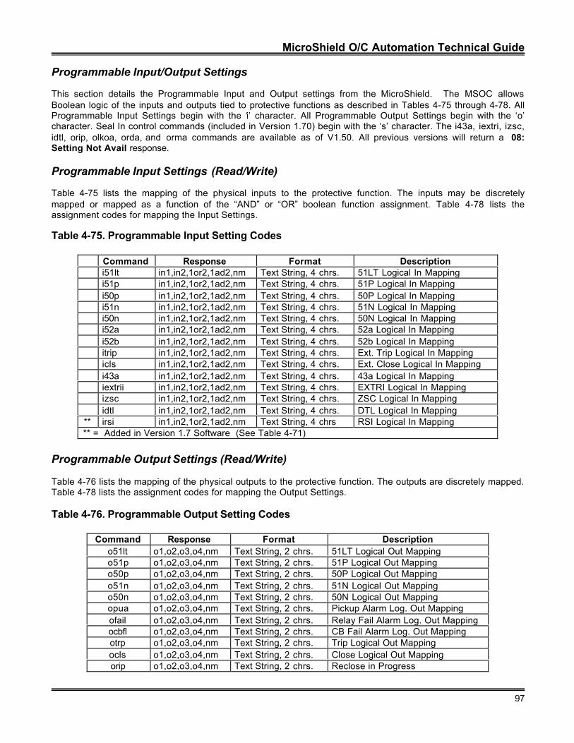
MicroShield O/C Automation Technical Guide
97
Programmable Input/Output Settings
This section details the Programmable Input and Output settings from the MicroShield. The MSOC allowsBoolean logic of the inputs and outputs tied to protective functions as described in Tables 4-75 through 4-78. AllProgrammable Input Settings begin with the ‘i’ character. All Programmable Output Settings begin with the ‘o’character. Seal In control commands (included in Version 1.70) begin with the ‘s’ character. The i43a, iextri, izsc,idtl, orip, olkoa, orda, and orma commands are available as of V1.50. All previous versions will return a 08:Setting Not Avail response.
Programmable Input Settings (Read/Write)
Table 4-75 lists the mapping of the physical inputs to the protective function. The inputs may be discretelymapped or mapped as a function of the “AND” or “OR” boolean function assignment. Table 4-78 lists theassignment codes for mapping the Input Settings.
Table 4-75. Programmable Input Setting Codes
Command Response Format Descriptioni51lt in1,in2,1or2,1ad2,nm Text String, 4 chrs. 51LT Logical In Mappingi51p in1,in2,1or2,1ad2,nm Text String, 4 chrs. 51P Logical In Mappingi50p in1,in2,1or2,1ad2,nm Text String, 4 chrs. 50P Logical In Mappingi51n in1,in2,1or2,1ad2,nm Text String, 4 chrs. 51N Logical In Mappingi50n in1,in2,1or2,1ad2,nm Text String, 4 chrs. 50N Logical In Mappingi52a in1,in2,1or2,1ad2,nm Text String, 4 chrs. 52a Logical In Mappingi52b in1,in2,1or2,1ad2,nm Text String, 4 chrs. 52b Logical In Mappingitrip in1,in2,1or2,1ad2,nm Text String, 4 chrs. Ext. Trip Logical In Mappingicls in1,in2,1or2,1ad2,nm Text String, 4 chrs. Ext. Close Logical In Mappingi43a in1,in2,1or2,1ad2,nm Text String, 4 chrs. 43a Logical In Mappingiextrii in1,in2,1or2,1ad2,nm Text String, 4 chrs. EXTRI Logical In Mappingizsc in1,in2,1or2,1ad2,nm Text String, 4 chrs. ZSC Logical In Mappingidtl in1,in2,1or2,1ad2,nm Text String, 4 chrs. DTL Logical In Mapping
** irsi in1,in2,1or2,1ad2,nm Text String, 4 chrs RSI Logical In Mapping** = Added in Version 1.7 Software (See Table 4-71)
Programmable Output Settings (Read/Write)
Table 4-76 lists the mapping of the physical outputs to the protective function. The outputs are discretely mapped.Table 4-78 lists the assignment codes for mapping the Output Settings.
Table 4-76. Programmable Output Setting Codes
Command Response Format Descriptiono51lt o1,o2,o3,o4,nm Text String, 2 chrs. 51LT Logical Out Mappingo51p o1,o2,o3,o4,nm Text String, 2 chrs. 51P Logical Out Mappingo50p o1,o2,o3,o4,nm Text String, 2 chrs. 50P Logical Out Mappingo51n o1,o2,o3,o4,nm Text String, 2 chrs. 51N Logical Out Mappingo50n o1,o2,o3,o4,nm Text String, 2 chrs. 50N Logical Out Mappingopua o1,o2,o3,o4,nm Text String, 2 chrs. Pickup Alarm Log. Out Mappingofail o1,o2,o3,o4,nm Text String, 2 chrs. Relay Fail Alarm Log. Out Mappingocbfl o1,o2,o3,o4,nm Text String, 2 chrs. CB Fail Alarm Log. Out Mappingotrp o1,o2,o3,o4,nm Text String, 2 chrs. Trip Logical Out Mappingocls o1,o2,o3,o4,nm Text String, 2 chrs. Close Logical Out Mappingorip o1,o2,o3,o4,nm Text String, 2 chrs. Reclose in Progress
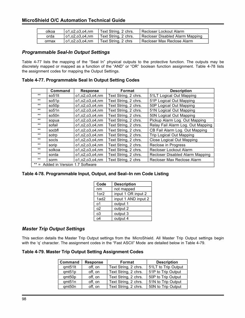
MicroShield O/C Automation Technical Guide
98
olkoa o1,o2,o3,o4,nm Text String, 2 chrs. Recloser Lockout Alarmorda o1,o2,o3,o4,nm Text String, 2 chrs. Recloser Disabled Alarm Mapping
ormax o1,o2,o3,o4,nm Text String, 2 chrs Recloser Max Reclose Alarm
Programmable Seal-In Output Settings
Table 4-77 lists the mapping of the “Seal In” physical outputs to the protective function. The outputs may bediscretely mapped or mapped as a function of the “AND” or “OR” boolean function assignment. Table 4-78 liststhe assignment codes for mapping the Output Settings.
Table 4-77. Programmable Seal In Output Setting Codes
Command Response Format Description** so51lt o1,o2,o3,o4,nm Text String, 2 chrs. 51LT Logical Out Mapping** so51p o1,o2,o3,o4,nm Text String, 2 chrs. 51P Logical Out Mapping** so50p o1,o2,o3,o4,nm Text String, 2 chrs. 50P Logical Out Mapping** so51n o1,o2,o3,o4,nm Text String, 2 chrs. 51N Logical Out Mapping** so50n o1,o2,o3,o4,nm Text String, 2 chrs. 50N Logical Out Mapping** sopua o1,o2,o3,o4,nm Text String, 2 chrs. Pickup Alarm Log. Out Mapping** sofail o1,o2,o3,o4,nm Text String, 2 chrs. Relay Fail Alarm Log. Out Mapping** socbfl o1,o2,o3,o4,nm Text String, 2 chrs. CB Fail Alarm Log. Out Mapping** sotrp o1,o2,o3,o4,nm Text String, 2 chrs. Trip Logical Out Mapping** socls o1,o2,o3,o4,nm Text String, 2 chrs. Close Logical Out Mapping** sorip o1,o2,o3,o4,nm Text String, 2 chrs. Reclose in Progress** solkoa o1,o2,o3,o4,nm Text String, 2 chrs. Recloser Lockout Alarm** sorda o1,o2,o3,o4,nm Text String, 2 chrs. Recloser Disabled Alarm Mapping** sorm o1,o2,o3,o4,nm Text String, 2 chrs Recloser Max Reclose Alarm
** = Added in Version 1.7 Software
Table 4-78. Programmable Input, Output, and Seal–In nm Code Listing
Code Descriptionnm not mapped1or2 input 1 OR input 21ad2 input 1 AND input 2o1 output 1o2 output 2o3 output 3o4 output 4
Master Trip Output Settings
This section details the Master Trip Output settings from the MicroShield. All Master Trip Output settings beginwith the ‘q’ character. The assignment codes in the “Fast ASCII” Mode are detailed below in Table 4-79.
Table 4-79. Master Trip Output Setting Assignment Codes
Command Response Format Descriptionqmt51lt off, on Text String, 2 chrs. 51LT to Trip Outputqmt51p off, on Text String, 2 chrs. 51P to Trip Outputqmt50p off, on Text String, 2 chrs. 50P to Trip Outputqmt51n off, on Text String, 2 chrs. 51N to Trip Outputqmt50n off, on Text String, 2 chrs. 50N to Trip Output
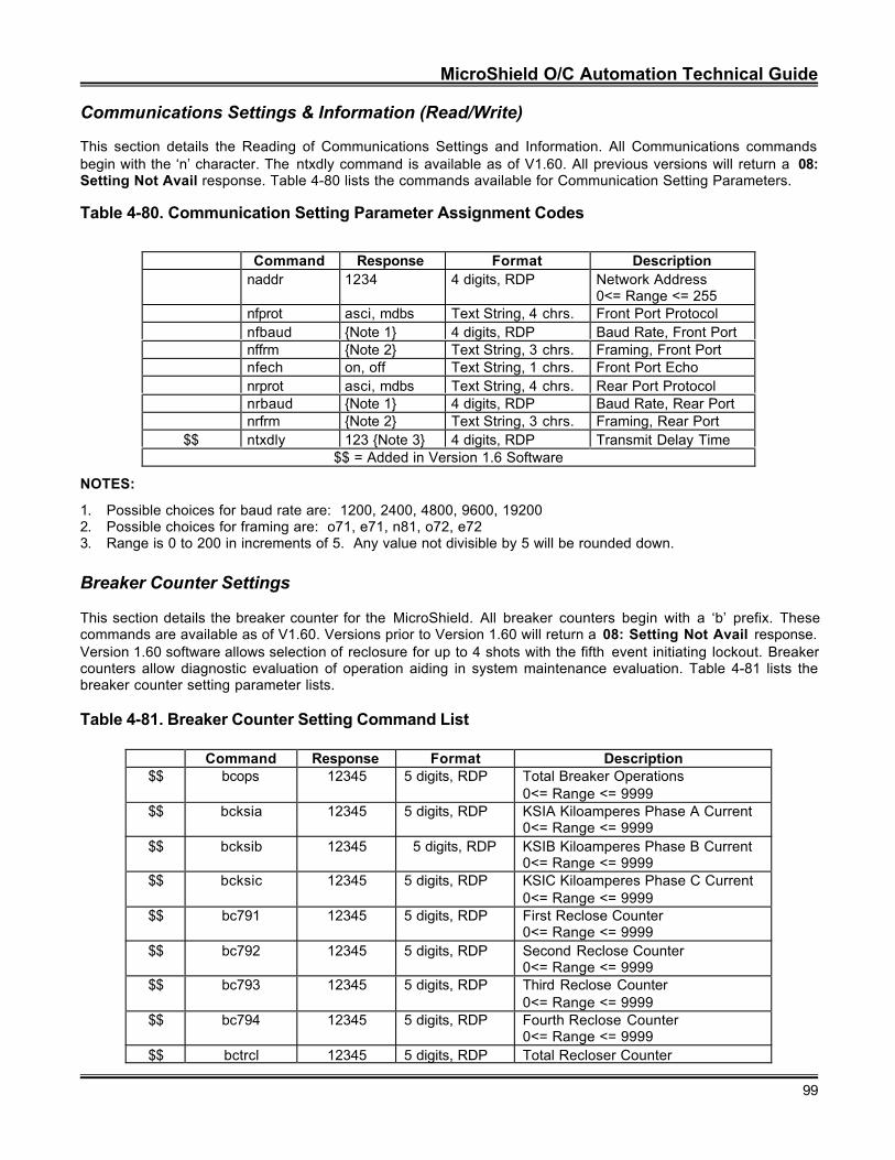
MicroShield O/C Automation Technical Guide
99
Communications Settings & Information (Read/Write)
This section details the Reading of Communications Settings and Information. All Communications commandsbegin with the ‘n’ character. The ntxdly command is available as of V1.60. All previous versions will return a 08:Setting Not Avail response. Table 4-80 lists the commands available for Communication Setting Parameters.
Table 4-80. Communication Setting Parameter Assignment Codes
Command Response Format Descriptionnaddr 1234 4 digits, RDP Network Address
0<= Range <= 255nfprot asci, mdbs Text String, 4 chrs. Front Port Protocolnfbaud {Note 1} 4 digits, RDP Baud Rate, Front Portnffrm {Note 2} Text String, 3 chrs. Framing, Front Portnfech on, off Text String, 1 chrs. Front Port Echonrprot asci, mdbs Text String, 4 chrs. Rear Port Protocolnrbaud {Note 1} 4 digits, RDP Baud Rate, Rear Portnrfrm {Note 2} Text String, 3 chrs. Framing, Rear Port
$$ ntxdly 123 {Note 3} 4 digits, RDP Transmit Delay Time$$ = Added in Version 1.6 Software
NOTES:
1. Possible choices for baud rate are: 1200, 2400, 4800, 9600, 192002. Possible choices for framing are: o71, e71, n81, o72, e723. Range is 0 to 200 in increments of 5. Any value not divisible by 5 will be rounded down.
Breaker Counter Settings
This section details the breaker counter for the MicroShield. All breaker counters begin with a ‘b’ prefix. Thesecommands are available as of V1.60. Versions prior to Version 1.60 will return a 08: Setting Not Avail response.Version 1.60 software allows selection of reclosure for up to 4 shots with the fifth event initiating lockout. Breakercounters allow diagnostic evaluation of operation aiding in system maintenance evaluation. Table 4-81 lists thebreaker counter setting parameter lists.
Table 4-81. Breaker Counter Setting Command List
Command Response Format Description$$ bcops 12345 5 digits, RDP Total Breaker Operations
0<= Range <= 9999$$ bcksia 12345 5 digits, RDP KSIA Kiloamperes Phase A Current
0<= Range <= 9999$$ bcksib 12345 5 digits, RDP KSIB Kiloamperes Phase B Current
0<= Range <= 9999$$ bcksic 12345 5 digits, RDP KSIC Kiloamperes Phase C Current
0<= Range <= 9999$$ bc791 12345 5 digits, RDP First Reclose Counter
0<= Range <= 9999$$ bc792 12345 5 digits, RDP Second Reclose Counter
0<= Range <= 9999$$ bc793 12345 5 digits, RDP Third Reclose Counter
0<= Range <= 9999$$ bc794 12345 5 digits, RDP Fourth Reclose Counter
0<= Range <= 9999$$ bctrcl 12345 5 digits, RDP Total Recloser Counter
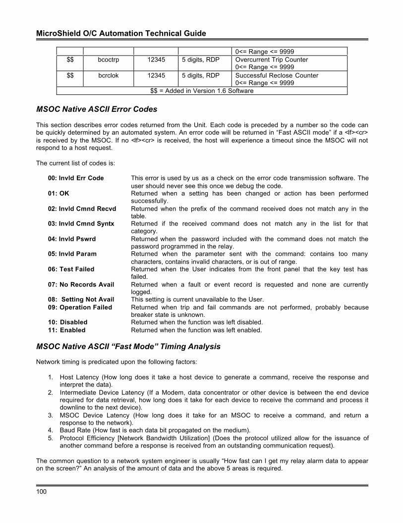
MicroShield O/C Automation Technical Guide
100
0<= Range <= 9999$$ bcoctrp 12345 5 digits, RDP Overcurrent Trip Counter
0<= Range <= 9999$$ bcrclok 12345 5 digits, RDP Successful Reclose Counter
0<= Range <= 9999$$ = Added in Version 1.6 Software
MSOC Native ASCII Error Codes
This section describes error codes returned from the Unit. Each code is preceded by a number so the code canbe quickly determined by an automated system. An error code will be returned in “Fast ASCII mode” if a <lf><cr>is received by the MSOC. If no <lf><cr> is received, the host will experience a timeout since the MSOC will notrespond to a host request.
The current list of codes is:
00: Invld Err Code This error is used by us as a check on the error code transmission software. Theuser should never see this once we debug the code.
01: OK Returned when a setting has been changed or action has been performedsuccessfully.
02: Invld Cmnd Recvd Returned when the prefix of the command received does not match any in thetable.
03: Invld Cmnd Syntx Returned if the received command does not match any in the list for thatcategory.
04: Invld Pswrd Returned when the password included with the command does not match thepassword programmed in the relay.
05: Invld Param Returned when the parameter sent with the command: contains too manycharacters, contains invalid characters, or is out of range.
06: Test Failed Returned when the User indicates from the front panel that the key test hasfailed.
07: No Records Avail Returned when a fault or event record is requested and none are currentlylogged.
08: Setting Not Avail This setting is current unavailable to the User.09: Operation Failed Returned when trip and fail commands are not performed, probably because
breaker state is unknown.10: Disabled Returned when the function was left disabled.11: Enabled Returned when the function was left enabled.
MSOC Native ASCII “Fast Mode” Timing Analysis
Network timing is predicated upon the following factors:
1. Host Latency (How long does it take a host device to generate a command, receive the response andinterpret the data).
2. Intermediate Device Latency (If a Modem, data concentrator or other device is between the end devicerequired for data retrieval, how long does it take for each device to receive the command and process itdownline to the next device).
3. MSOC Device Latency (How long does it take for an MSOC to receive a command, and return aresponse to the network).
4. Baud Rate (How fast is each data bit propagated on the medium).5. Protocol Efficiency [Network Bandwidth Utilization] (Does the protocol utilized allow for the issuance of
another command before a response is received from an outstanding communication request).
The common question to a network system engineer is usually “How fast can I get my relay alarm data to appearon the screen?” An analysis of the amount of data and the above 5 areas is required.
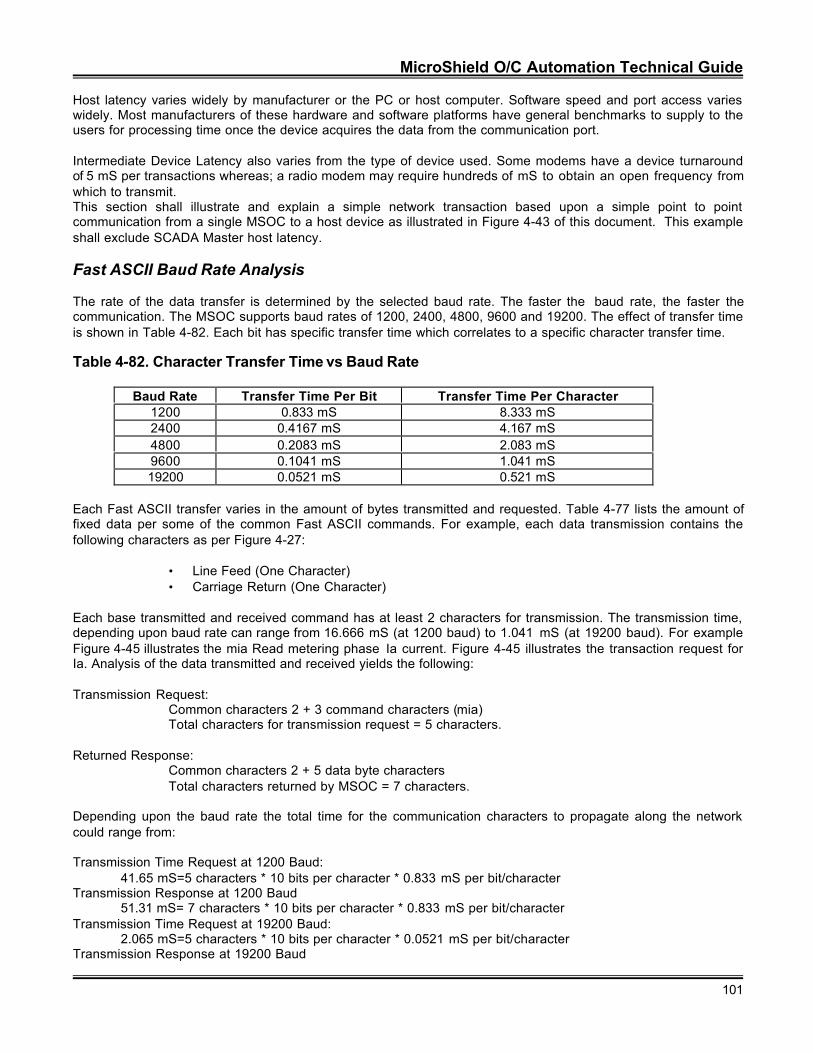
MicroShield O/C Automation Technical Guide
101
Host latency varies widely by manufacturer or the PC or host computer. Software speed and port access varieswidely. Most manufacturers of these hardware and software platforms have general benchmarks to supply to theusers for processing time once the device acquires the data from the communication port.
Intermediate Device Latency also varies from the type of device used. Some modems have a device turnaroundof 5 mS per transactions whereas; a radio modem may require hundreds of mS to obtain an open frequency fromwhich to transmit.This section shall illustrate and explain a simple network transaction based upon a simple point to pointcommunication from a single MSOC to a host device as illustrated in Figure 4-43 of this document. This exampleshall exclude SCADA Master host latency.
Fast ASCII Baud Rate Analysis
The rate of the data transfer is determined by the selected baud rate. The faster the baud rate, the faster thecommunication. The MSOC supports baud rates of 1200, 2400, 4800, 9600 and 19200. The effect of transfer timeis shown in Table 4-82. Each bit has specific transfer time which correlates to a specific character transfer time.
Table 4-82. Character Transfer Time vs Baud Rate
Baud Rate Transfer Time Per Bit Transfer Time Per Character1200 0.833 mS 8.333 mS2400 0.4167 mS 4.167 mS4800 0.2083 mS 2.083 mS9600 0.1041 mS 1.041 mS19200 0.0521 mS 0.521 mS
Each Fast ASCII transfer varies in the amount of bytes transmitted and requested. Table 4-77 lists the amount offixed data per some of the common Fast ASCII commands. For example, each data transmission contains thefollowing characters as per Figure 4-27:
• Line Feed (One Character)• Carriage Return (One Character)
Each base transmitted and received command has at least 2 characters for transmission. The transmission time,depending upon baud rate can range from 16.666 mS (at 1200 baud) to 1.041 mS (at 19200 baud). For exampleFigure 4-45 illustrates the mia Read metering phase Ia current. Figure 4-45 illustrates the transaction request forIa. Analysis of the data transmitted and received yields the following:
Transmission Request:Common characters 2 + 3 command characters (mia)Total characters for transmission request = 5 characters.
Returned Response:Common characters 2 + 5 data byte charactersTotal characters returned by MSOC = 7 characters.
Depending upon the baud rate the total time for the communication characters to propagate along the networkcould range from:
Transmission Time Request at 1200 Baud:41.65 mS=5 characters * 10 bits per character * 0.833 mS per bit/character
Transmission Response at 1200 Baud51.31 mS= 7 characters * 10 bits per character * 0.833 mS per bit/character
Transmission Time Request at 19200 Baud:2.065 mS=5 characters * 10 bits per character * 0.0521 mS per bit/character
Transmission Response at 19200 Baud
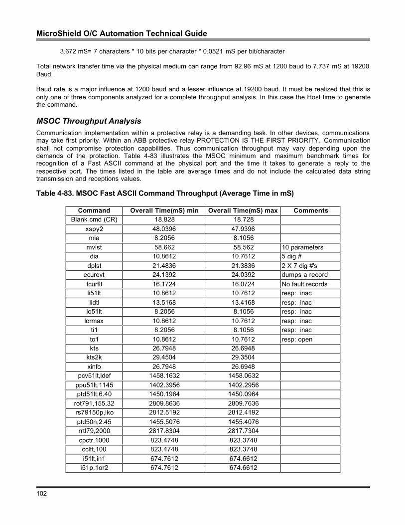
MicroShield O/C Automation Technical Guide
102
3.672 mS= 7 characters * 10 bits per character * 0.0521 mS per bit/character
Total network transfer time via the physical medium can range from 92.96 mS at 1200 baud to 7.737 mS at 19200Baud.
Baud rate is a major influence at 1200 baud and a lesser influence at 19200 baud. It must be realized that this isonly one of three components analyzed for a complete throughput analysis. In this case the Host time to generatethe command.
MSOC Throughput AnalysisCommunication implementation within a protective relay is a demanding task. In other devices, communicationsmay take first priority. Within an ABB protective relay PROTECTION IS THE FIRST PRIORITY. Communicationshall not compromise protection capabilities. Thus communication throughput may vary depending upon thedemands of the protection. Table 4-83 illustrates the MSOC minimum and maximum benchmark times forrecognition of a Fast ASCII command at the physical port and the time it takes to generate a reply to therespective port. The times listed in the table are average times and do not include the calculated data stringtransmission and receptions values.
Table 4-83. MSOC Fast ASCII Command Throughput (Average Time in mS)
Command Overall Time(mS) min Overall Time(mS) max CommentsBlank cmd (CR) 18.828 18.728
xspy2 48.0396 47.9396mia 8.2056 8.1056
mvlst 58.662 58.562 10 parametersdia 10.8612 10.7612 5 dig #
dplst 21.4836 21.3836 2 X 7 dig #'securevt 24.1392 24.0392 dumps a recordfcurflt 16.1724 16.0724 No fault recordsli51lt 10.8612 10.7612 resp: inaclidtl 13.5168 13.4168 resp: inac
lo51lt 8.2056 8.1056 resp: inaclormax 10.8612 10.7612 resp: inac
ti1 8.2056 8.1056 resp: inacto1 10.8612 10.7612 resp: openkts 26.7948 26.6948
kts2k 29.4504 29.3504xinfo 26.7948 26.6948
pcv51lt,ldef 1458.1632 1458.0632ppu51lt,1145 1402.3956 1402.2956ptd51lt,6.40 1450.1964 1450.0964
rot791,155.32 2809.8636 2809.7636rs79150p,lko 2812.5192 2812.4192ptd50n,2.45 1455.5076 1455.4076rrtl79,2000 2817.8304 2817.7304cpctr,1000 823.4748 823.3748cclft,100 823.4748 823.3748i51lt,in1 674.7612 674.6612
i51p,1or2 674.7612 674.6612
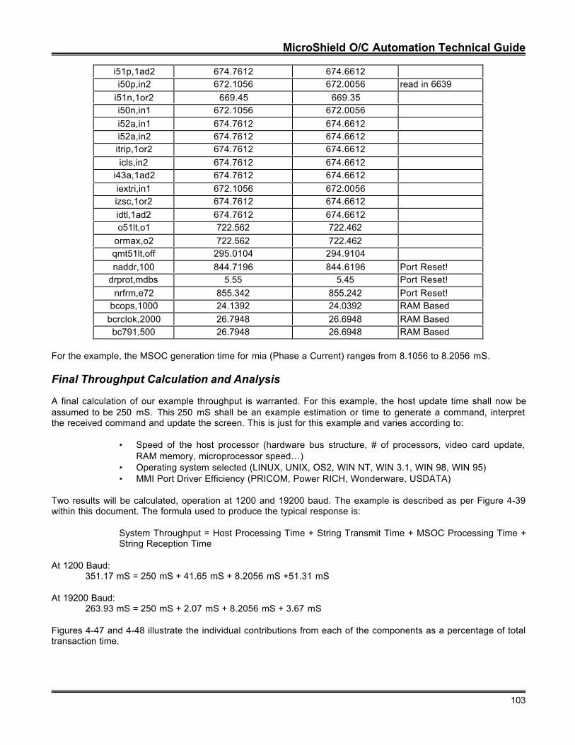
MicroShield O/C Automation Technical Guide
103
i51p,1ad2 674.7612 674.6612i50p,in2 672.1056 672.0056 read in 6639
i51n,1or2 669.45 669.35i50n,in1 672.1056 672.0056i52a,in1 674.7612 674.6612i52a,in2 674.7612 674.6612itrip,1or2 674.7612 674.6612icls,in2 674.7612 674.6612
i43a,1ad2 674.7612 674.6612iextri,in1 672.1056 672.0056izsc,1or2 674.7612 674.6612idtl,1ad2 674.7612 674.6612o51lt,o1 722.562 722.462
ormax,o2 722.562 722.462qmt51lt,off 295.0104 294.9104naddr,100 844.7196 844.6196 Port Reset!
drprot,mdbs 5.55 5.45 Port Reset!nrfrm,e72 855.342 855.242 Port Reset!
bcops,1000 24.1392 24.0392 RAM Basedbcrclok,2000 26.7948 26.6948 RAM Basedbc791,500 26.7948 26.6948 RAM Based
For the example, the MSOC generation time for mia (Phase a Current) ranges from 8.1056 to 8.2056 mS.
Final Throughput Calculation and Analysis
A final calculation of our example throughput is warranted. For this example, the host update time shall now beassumed to be 250 mS. This 250 mS shall be an example estimation or time to generate a command, interpretthe received command and update the screen. This is just for this example and varies according to:
• Speed of the host processor (hardware bus structure, # of processors, video card update,RAM memory, microprocessor speed…)
• Operating system selected (LINUX, UNIX, OS2, WIN NT, WIN 3.1, WIN 98, WIN 95)• MMI Port Driver Efficiency (PRICOM, Power RICH, Wonderware, USDATA)
Two results will be calculated, operation at 1200 and 19200 baud. The example is described as per Figure 4-39within this document. The formula used to produce the typical response is:
System Throughput = Host Processing Time + String Transmit Time + MSOC Processing Time +String Reception Time
At 1200 Baud:351.17 mS = 250 mS + 41.65 mS + 8.2056 mS +51.31 mS
At 19200 Baud:263.93 mS = 250 mS + 2.07 mS + 8.2056 mS + 3.67 mS
Figures 4-47 and 4-48 illustrate the individual contributions from each of the components as a percentage of totaltransaction time.
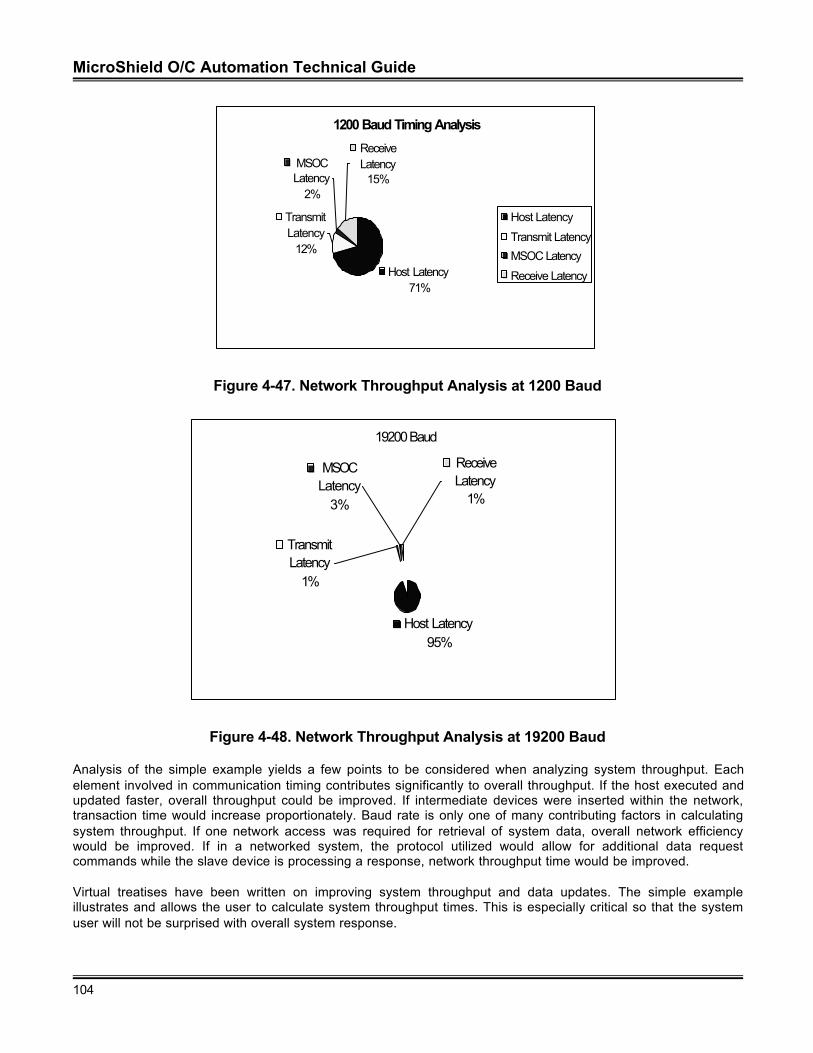
MicroShield O/C Automation Technical Guide
104
Figure 4-47. Network Throughput Analysis at 1200 Baud
Figure 4-48. Network Throughput Analysis at 19200 Baud
Analysis of the simple example yields a few points to be considered when analyzing system throughput. Eachelement involved in communication timing contributes significantly to overall throughput. If the host executed andupdated faster, overall throughput could be improved. If intermediate devices were inserted within the network,transaction time would increase proportionately. Baud rate is only one of many contributing factors in calculatingsystem throughput. If one network access was required for retrieval of system data, overall network efficiencywould be improved. If in a networked system, the protocol utilized would allow for additional data requestcommands while the slave device is processing a response, network throughput time would be improved.
Virtual treatises have been written on improving system throughput and data updates. The simple exampleillustrates and allows the user to calculate system throughput times. This is especially critical so that the systemuser will not be surprised with overall system response.
1200 Baud Timing Analysis
Host Latency71%
Transmit Latency
12%
MSOC Latency
2%
Receive Latency
15%
Host Latency
Transmit Latency
MSOC Latency
Receive Latency
19200 Baud
Host Latency95%
Receive Latency
1%
MSOC Latency
3%
Transmit Latency
1%
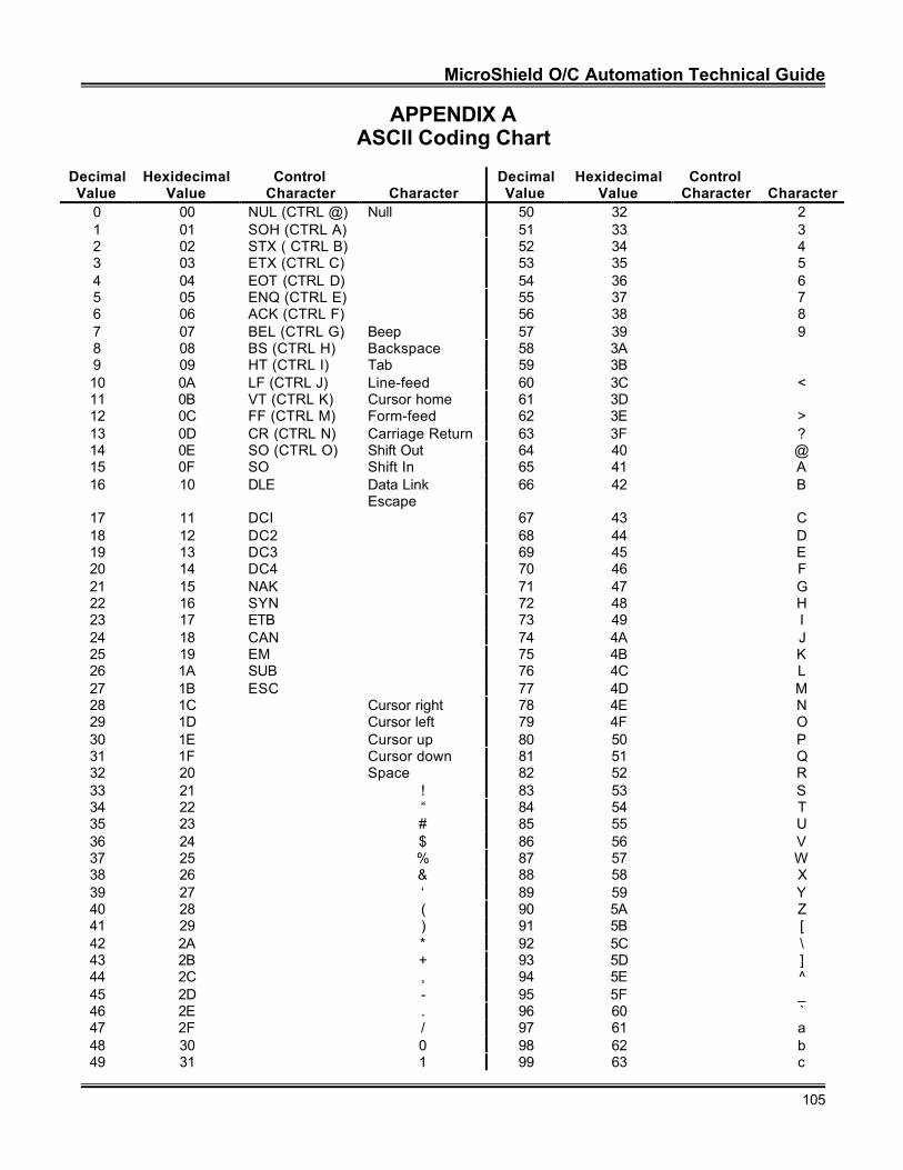
MicroShield O/C Automation Technical Guide
105
APPENDIX AASCII Coding Chart
DecimalValue
HexidecimalValue
ControlCharacter Character
DecimalValue
HexidecimalValue
ControlCharacter Character
0 00 NUL (CTRL @) Null 50 32 21 01 SOH (CTRL A) 51 33 32 02 STX ( CTRL B) 52 34 43 03 ETX (CTRL C) 53 35 54 04 EOT (CTRL D) 54 36 65 05 ENQ (CTRL E) 55 37 76 06 ACK (CTRL F) 56 38 87 07 BEL (CTRL G) Beep 57 39 98 08 BS (CTRL H) Backspace 58 3A9 09 HT (CTRL I) Tab 59 3B10 0A LF (CTRL J) Line-feed 60 3C <11 0B VT (CTRL K) Cursor home 61 3D12 0C FF (CTRL M) Form-feed 62 3E >13 0D CR (CTRL N) Carriage Return 63 3F ?14 0E SO (CTRL O) Shift Out 64 40 @15 0F SO Shift In 65 41 A16 10 DLE Data Link
Escape66 42 B
17 11 DCI 67 43 C18 12 DC2 68 44 D19 13 DC3 69 45 E20 14 DC4 70 46 F21 15 NAK 71 47 G22 16 SYN 72 48 H23 17 ETB 73 49 I24 18 CAN 74 4A J25 19 EM 75 4B K26 1A SUB 76 4C L27 1B ESC 77 4D M28 1C Cursor right 78 4E N29 1D Cursor left 79 4F O30 1E Cursor up 80 50 P31 1F Cursor down 81 51 Q32 20 Space 82 52 R33 21 ! 83 53 S34 22 “ 84 54 T35 23 # 85 55 U36 24 $ 86 56 V37 25 % 87 57 W38 26 & 88 58 X39 27 ‘ 89 59 Y40 28 ( 90 5A Z41 29 ) 91 5B [42 2A * 92 5C \43 2B + 93 5D ]44 2C , 94 5E ^45 2D - 95 5F _46 2E . 96 60 `47 2F / 97 61 a48 30 0 98 62 b49 31 1 99 63 c
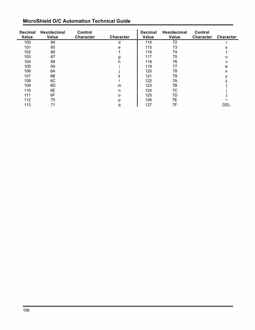
MicroShield O/C Automation Technical Guide
106
DecimalValue
HexidecimalValue
ControlCharacter Character
DecimalValue
HexidecimalValue
ControlCharacter Character
100 64 d 114 72 r101 65 e 115 73 s102 66 f 116 74 t103 67 g 117 75 u104 68 h 118 76 v105 69 i 119 77 w106 6A j 120 78 x107 6B k 121 79 y108 6C l 122 7A z109 6D m 123 7B {110 6E n 124 7C |111 6F o 125 7D }112 70 p 126 7E ~113 71 q 127 7F DEL
MicroShield O/C Automation Technical Guide
107
APPENDIX B
RS 232 Device Connectivity
RS 232 Point to Point Connectivity for the DPU/TPU/GPU 2000(R) Protection Units
Today’s requirements for rapid data acquisition necessitate understanding the physical interface requirements forconnection of a DPU2000(R), TPU2000(R), or GPU2000R. One of the many available options within the ABBDPU2000(R), TPU2000(R), or GPU2000R units is RS 232 connectivity. What follows is an explanation of RS 232serial port connectivity and physical connection considerations in a point to point communication architecture.
What is RS 232?
RS 232 is perhaps the most utilized and least understood communication interface in use. RS 232 is sometimesmisinterpreted to be a protocol; it is in fact a physical interface. A physical interface is the hardware and networkphysical media used to propagate a signal between devices. Examples of physical interfaces are RS 232 seriallink, printer parallel port, current loop, V. 24, IEEE Bus… Examples of network media are, twisted copper pair,coaxial cable, free air…
A protocol is a specific set of rules and regulations regulating data transmission and reception. Examples ofprotocols are: DNP 3.0, Modbus, INCOM, etc., which can communicate over a variety of physical interfaces andmedia. Every DPU2000(R), TPU2000(R), or GPU2000R protective device includes an RS 232 connection as partof the base product.
RS 232 gained widespread acceptance due to its ability to connect to another RS 232 device or to a modem. Amodem is a device, which takes a communication signal and modulates it into another form. Common forms ofmodems include telephone, fiber optic, microwave, and radio frequency. Modem connectivity allows attachment ofmultiple devices on a communication network or allows extension of communication distances in a network withtwo nodes. Physical connection of two devices or more than two devices require differing approaches. This noteshall explore point to point serial communication in depth and illustrate its inclusion into substation applications.The first RS 232 specification issued by the Electronic Industries Association defined the interface as consisting of25 pins within a D shell connector. One of four categories of functionality is assigned to each pin (ground, data,control and timing). With the introduction of the IBM PC AT, the RS 232 port was reduced in form factor andfunctionality to consist of 9 pins within a D shell connector. That has been the de-facto standard for RS 232 portimplementation included on most electronic equipment. The DPU/TPU/GPU 2000(R) family of protective devicesincludes at least one RS 232 port emulating a common utility industry protocol.
RS 232 Connectivity Issues
Common issues arise when two devices communicate. Typical communication architectures are illustrated inFigures B1 and B2. Configuration of an ABB DPU2000(R), TPU2000(R), or GPU2000R family of protection relaysis accomplished via a software program called ECP (External Communication Program). Figure B1 illustrates atypical connection in a point to point topology. DPU2000R configuration through a personal computer requires twosteps, 1.) Correct physical interconnection between the PC and DPU2000, 2.) Configuration of the DPU and thePC with a common protocol. The DPU2000(R), TPU2000(R), or GPU2000R protocol may be assigned to eachport through a configuration sequence via the front keypad of the device. Please refer to the respective productmanuals for communication port configuration instructions.
Figure B2 illustrates another typical communications topology, multi-drop. A typical implementation of multi-droparchitecture is one in which a host computer (for example, a personal computer with Pricom SE software) collectsmetering information from a distributed set of protective relays. In this case a great distance separates thepersonal computer from each device. However, an RS 232 port is available on each node. Device interconnectionis possible through the addition of a modem or line driver. Interconnection of these devices requires a differentsetup and implementation process. The topic of multi-drop topology is covered in other application notes.
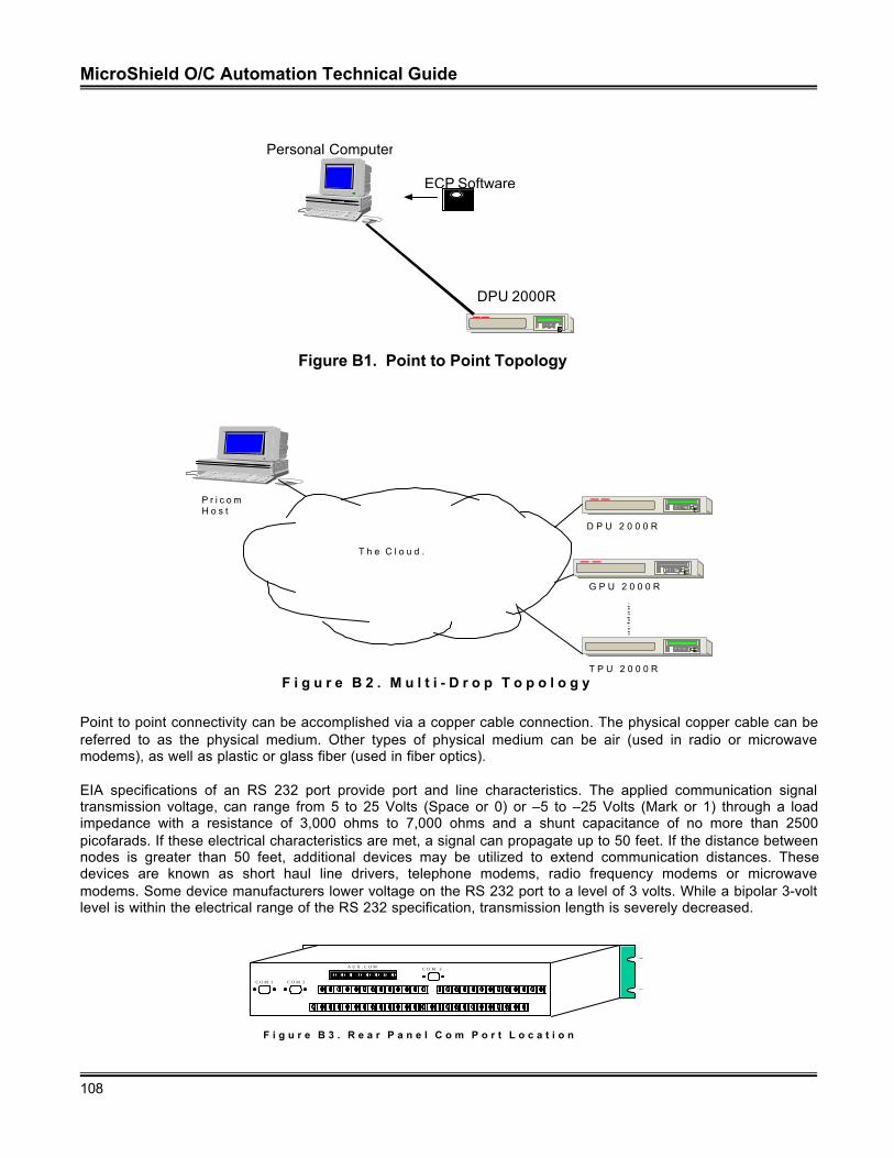
MicroShield O/C Automation Technical Guide
108
P r i c o mH o s t
T P U 2 0 0 0 R
EC
EC
EC
D P U 2 0 0 0 R
T h e C l o u d .
G P U 2 0 0 0 R
F i g u r e B 2 . M u l t i - D r o p T o p o l o g y
Point to point connectivity can be accomplished via a copper cable connection. The physical copper cable can bereferred to as the physical medium. Other types of physical medium can be air (used in radio or microwavemodems), as well as plastic or glass fiber (used in fiber optics).
EIA specifications of an RS 232 port provide port and line characteristics. The applied communication signaltransmission voltage, can range from 5 to 25 Volts (Space or 0) or –5 to –25 Volts (Mark or 1) through a loadimpedance with a resistance of 3,000 ohms to 7,000 ohms and a shunt capacitance of no more than 2500picofarads. If these electrical characteristics are met, a signal can propagate up to 50 feet. If the distance betweennodes is greater than 50 feet, additional devices may be utilized to extend communication distances. Thesedevices are known as short haul line drivers, telephone modems, radio frequency modems or microwavemodems. Some device manufacturers lower voltage on the RS 232 port to a level of 3 volts. While a bipolar 3-voltlevel is within the electrical range of the RS 232 specification, transmission length is severely decreased.
F i g u r e B 3 . R e a r P a n e l C o m P o r t L o c a t i o n
C O M 1 C O M 2
C O M 3A U X . C O M
EC
Figure B1. Point to Point Topology
DPU 2000R
Personal Computer
ECP Software
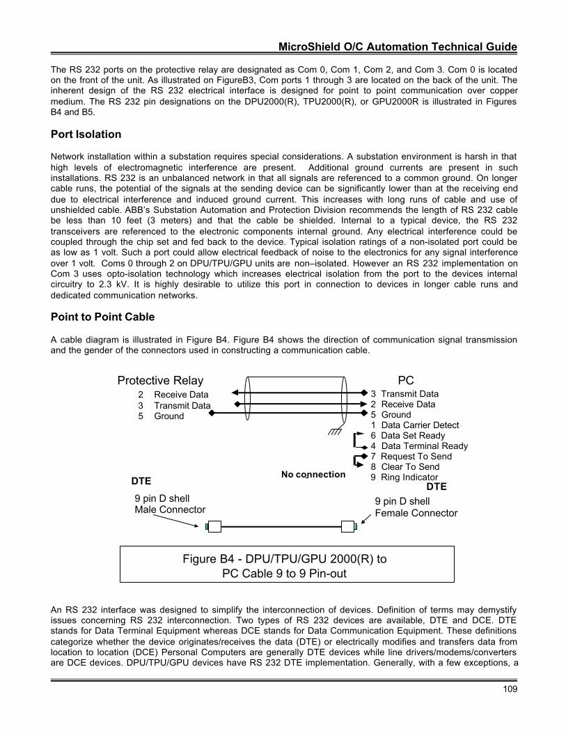
MicroShield O/C Automation Technical Guide
109
The RS 232 ports on the protective relay are designated as Com 0, Com 1, Com 2, and Com 3. Com 0 is locatedon the front of the unit. As illustrated on FigureB3, Com ports 1 through 3 are located on the back of the unit. Theinherent design of the RS 232 electrical interface is designed for point to point communication over coppermedium. The RS 232 pin designations on the DPU2000(R), TPU2000(R), or GPU2000R is illustrated in FiguresB4 and B5.
Port Isolation
Network installation within a substation requires special considerations. A substation environment is harsh in thathigh levels of electromagnetic interference are present. Additional ground currents are present in suchinstallations. RS 232 is an unbalanced network in that all signals are referenced to a common ground. On longercable runs, the potential of the signals at the sending device can be significantly lower than at the receiving enddue to electrical interference and induced ground current. This increases with long runs of cable and use ofunshielded cable. ABB’s Substation Automation and Protection Division recommends the length of RS 232 cablebe less than 10 feet (3 meters) and that the cable be shielded. Internal to a typical device, the RS 232transceivers are referenced to the electronic components internal ground. Any electrical interference could becoupled through the chip set and fed back to the device. Typical isolation ratings of a non-isolated port could beas low as 1 volt. Such a port could allow electrical feedback of noise to the electronics for any signal interferenceover 1 volt. Coms 0 through 2 on DPU/TPU/GPU units are non–isolated. However an RS 232 implementation onCom 3 uses opto-isolation technology which increases electrical isolation from the port to the devices internalcircuitry to 2.3 kV. It is highly desirable to utilize this port in connection to devices in longer cable runs anddedicated communication networks.
Point to Point Cable
A cable diagram is illustrated in Figure B4. Figure B4 shows the direction of communication signal transmissionand the gender of the connectors used in constructing a communication cable.
Figure B4 - DPU/TPU/GPU 2000(R) toPC Cable 9 to 9 Pin-out
Protective Relay PC2 Receive Data 3 Transmit Data3 Transmit Data 2 Receive Data5 Ground 5 Ground
1 Data Carrier Detect6 Data Set Ready
4 Data Terminal Ready7 Request To Send8 Clear To Send
-No connection 9 Ring Indicator
9 pin D shellMale Connector
9 pin D shellFemale Connector
DTE DTE
An RS 232 interface was designed to simplify the interconnection of devices. Definition of terms may demystifyissues concerning RS 232 interconnection. Two types of RS 232 devices are available, DTE and DCE. DTEstands for Data Terminal Equipment whereas DCE stands for Data Communication Equipment. These definitionscategorize whether the device originates/receives the data (DTE) or electrically modifies and transfers data fromlocation to location (DCE) Personal Computers are generally DTE devices while line drivers/modems/convertersare DCE devices. DPU/TPU/GPU devices have RS 232 DTE implementation. Generally, with a few exceptions, a
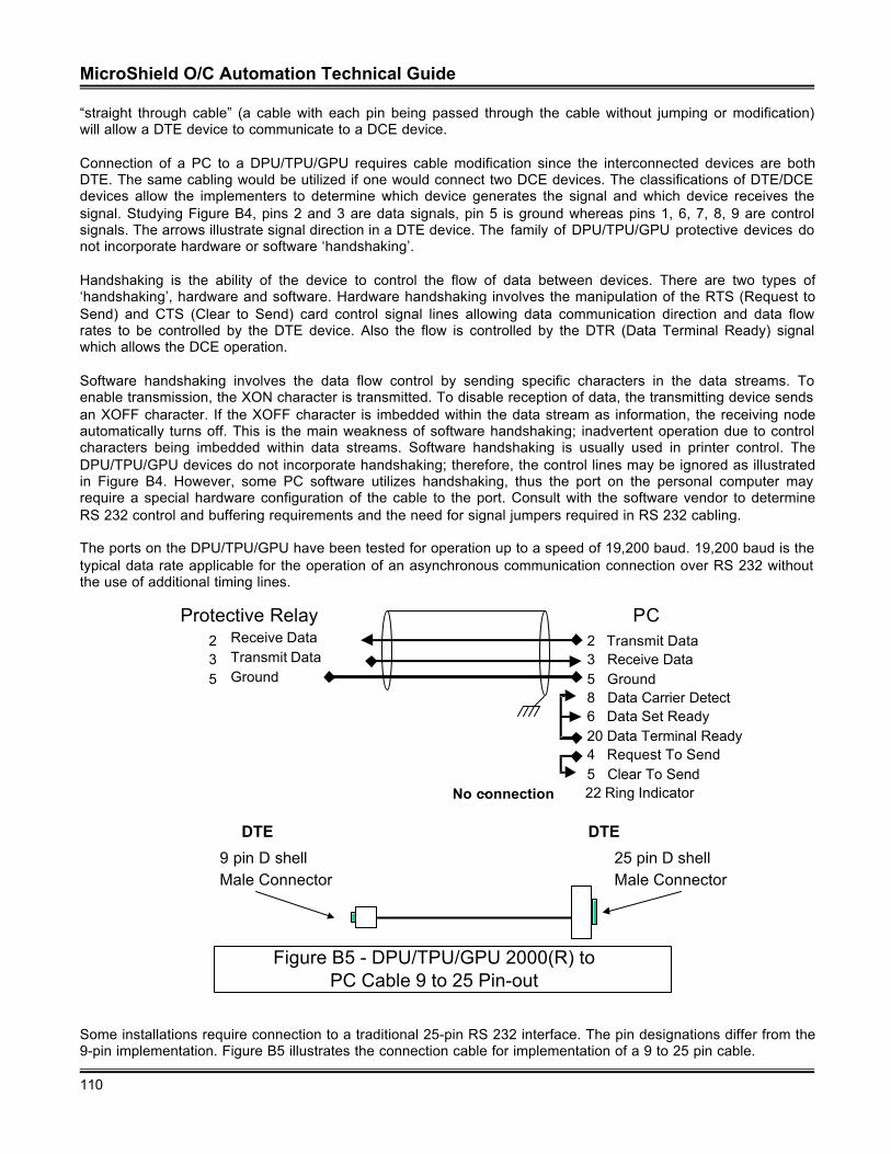
MicroShield O/C Automation Technical Guide
110
“straight through cable” (a cable with each pin being passed through the cable without jumping or modification)will allow a DTE device to communicate to a DCE device.
Connection of a PC to a DPU/TPU/GPU requires cable modification since the interconnected devices are bothDTE. The same cabling would be utilized if one would connect two DCE devices. The classifications of DTE/DCEdevices allow the implementers to determine which device generates the signal and which device receives thesignal. Studying Figure B4, pins 2 and 3 are data signals, pin 5 is ground whereas pins 1, 6, 7, 8, 9 are controlsignals. The arrows illustrate signal direction in a DTE device. The family of DPU/TPU/GPU protective devices donot incorporate hardware or software ‘handshaking’.
Handshaking is the ability of the device to control the flow of data between devices. There are two types of‘handshaking’, hardware and software. Hardware handshaking involves the manipulation of the RTS (Request toSend) and CTS (Clear to Send) card control signal lines allowing data communication direction and data flowrates to be controlled by the DTE device. Also the flow is controlled by the DTR (Data Terminal Ready) signalwhich allows the DCE operation.
Software handshaking involves the data flow control by sending specific characters in the data streams. Toenable transmission, the XON character is transmitted. To disable reception of data, the transmitting device sendsan XOFF character. If the XOFF character is imbedded within the data stream as information, the receiving nodeautomatically turns off. This is the main weakness of software handshaking; inadvertent operation due to controlcharacters being imbedded within data streams. Software handshaking is usually used in printer control. TheDPU/TPU/GPU devices do not incorporate handshaking; therefore, the control lines may be ignored as illustratedin Figure B4. However, some PC software utilizes handshaking, thus the port on the personal computer mayrequire a special hardware configuration of the cable to the port. Consult with the software vendor to determineRS 232 control and buffering requirements and the need for signal jumpers required in RS 232 cabling.
The ports on the DPU/TPU/GPU have been tested for operation up to a speed of 19,200 baud. 19,200 baud is thetypical data rate applicable for the operation of an asynchronous communication connection over RS 232 withoutthe use of additional timing lines.
Figure B5 - DPU/TPU/GPU 2000(R) to PC Cable 9 to 25 Pin-out
Protective Relay PC2 Receive Data 2 Transmit Data3 Transmit Data 3 Receive Data5 Ground 5 Ground
8 Data Carrier Detect6 Data Set Ready
20 Data Terminal Ready4 Request To Send5 Clear To Send
-No connection 22 Ring Indicator
9 pin D shellMale Connector
25 pin D shellMale Connector
DTE DTE
Some installations require connection to a traditional 25-pin RS 232 interface. The pin designations differ from the9-pin implementation. Figure B5 illustrates the connection cable for implementation of a 9 to 25 pin cable.

MicroShield O/C Automation Technical Guide
111
Conclusion
RS 232 communication through a copper connection in a point to point configuration is easily achieved with thecorrect cable connection. Understanding common terms as DTE, DCE and handshaking are important indesigning the correct cable to connect similar devices on an RS 232 physical interface.
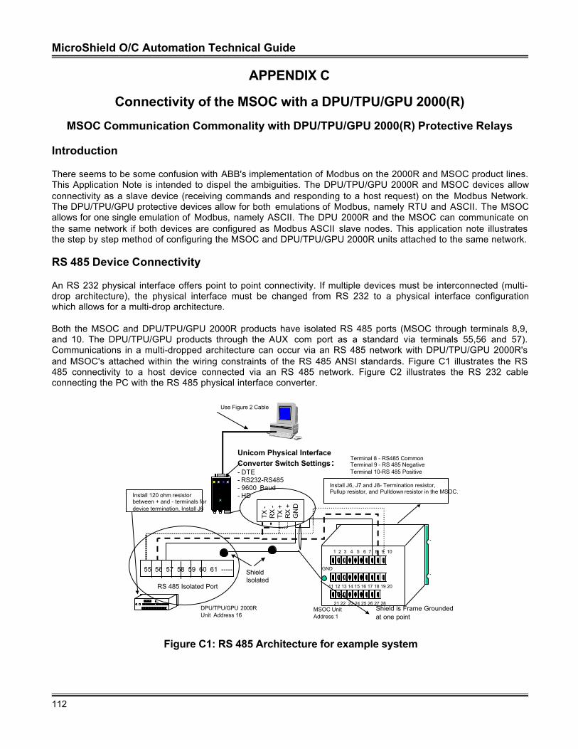
MicroShield O/C Automation Technical Guide
112
APPENDIX C
Connectivity of the MSOC with a DPU/TPU/GPU 2000(R)
MSOC Communication Commonality with DPU/TPU/GPU 2000(R) Protective Relays
Introduction
There seems to be some confusion with ABB's implementation of Modbus on the 2000R and MSOC product lines.This Application Note is intended to dispel the ambiguities. The DPU/TPU/GPU 2000R and MSOC devices allowconnectivity as a slave device (receiving commands and responding to a host request) on the Modbus Network.The DPU/TPU/GPU protective devices allow for both emulations of Modbus, namely RTU and ASCII. The MSOCallows for one single emulation of Modbus, namely ASCII. The DPU 2000R and the MSOC can communicate onthe same network if both devices are configured as Modbus ASCII slave nodes. This application note illustratesthe step by step method of configuring the MSOC and DPU/TPU/GPU 2000R units attached to the same network.
RS 485 Device Connectivity
An RS 232 physical interface offers point to point connectivity. If multiple devices must be interconnected (multi-drop architecture), the physical interface must be changed from RS 232 to a physical interface configurationwhich allows for a multi-drop architecture.
Both the MSOC and DPU/TPU/GPU 2000R products have isolated RS 485 ports (MSOC through terminals 8,9,and 10. The DPU/TPU/GPU products through the AUX com port as a standard via terminals 55,56 and 57).Communications in a multi-dropped architecture can occur via an RS 485 network with DPU/TPU/GPU 2000R'sand MSOC's attached within the wiring constraints of the RS 485 ANSI standards. Figure C1 illustrates the RS485 connectivity to a host device connected via an RS 485 network. Figure C2 illustrates the RS 232 cableconnecting the PC with the RS 485 physical interface converter.
Unicom Physical Interface Converter Switch Settings:- DTE- RS232-RS485- 9600 Baud- HD
Use Figure 2 Cable
TX
-R
X -
TX +
RX
+G
ND
Shield is Frame Grounded at one point
1 2 3 4 5 6 7 8 9 10
11 12 13 14 15 16 17 18 19 20
21 22 23 24 25 26 27 28
GND
Terminal 8 - RS485 CommonTerminal 9 - RS 485 NegativeTerminal 10-RS 485 Positive
Install J6, J7 and J8- Termination resistor,Pullup resistor, and Pulldown resistor in the MSOC.
Install 120 ohm resistorbetween + and - terminals fordevice termination. Install J6
3
55 56 57 58 59 60 61 -----
RS 485 Isolated Port
Shield Isolated
DPU/TPU/GPU 2000RUnit Address 16
MSOC UnitAddress 1
Figure C1: RS 485 Architecture for example system
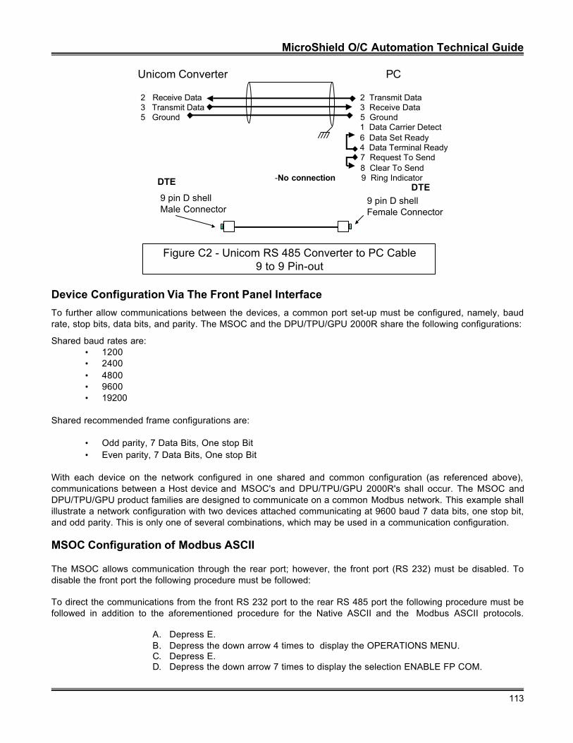
MicroShield O/C Automation Technical Guide
113
Figure C2 - Unicom RS 485 Converter to PC Cable9 to 9 Pin-out
Unicom Converter PC
2 Receive Data 2 Transmit Data3 Transmit Data 3 Receive Data5 Ground 5 Ground
1 Data Carrier Detect 6 Data Set Ready
4 Data Terminal Ready 7 Request To Send 8 Clear To Send
-No connection 9 Ring Indicator
9 pin D shellMale Connector
9 pin D shellFemale Connector
DTEDTE
Device Configuration Via The Front Panel Interface
To further allow communications between the devices, a common port set-up must be configured, namely, baudrate, stop bits, data bits, and parity. The MSOC and the DPU/TPU/GPU 2000R share the following configurations:
Shared baud rates are:• 1200• 2400• 4800• 9600• 19200
Shared recommended frame configurations are:
• Odd parity, 7 Data Bits, One stop Bit• Even parity, 7 Data Bits, One stop Bit
With each device on the network configured in one shared and common configuration (as referenced above),communications between a Host device and MSOC's and DPU/TPU/GPU 2000R's shall occur. The MSOC andDPU/TPU/GPU product families are designed to communicate on a common Modbus network. This example shallillustrate a network configuration with two devices attached communicating at 9600 baud 7 data bits, one stop bit,and odd parity. This is only one of several combinations, which may be used in a communication configuration.
MSOC Configuration of Modbus ASCII
The MSOC allows communication through the rear port; however, the front port (RS 232) must be disabled. Todisable the front port the following procedure must be followed:
To direct the communications from the front RS 232 port to the rear RS 485 port the following procedure must befollowed in addition to the aforementioned procedure for the Native ASCII and the Modbus ASCII protocols.
A. Depress E.B. Depress the down arrow 4 times to display the OPERATIONS MENU.C. Depress E.D. Depress the down arrow 7 times to display the selection ENABLE FP COM.
MicroShield O/C Automation Technical Guide
114
E. Depress E.F. Enter the Password as described in the previous illustrations.G. The user shall be prompted, with the selection ENABLE FP < >. If the selection is
YES, then the Front Port (RS 232) shall have the communications options configuredvia the above process. If the Selection is NO then the Rear Port (RS 485) shall beenabled with the protocol configured via the above process. Enter the correctpassword for the unit. Then Depress E to accept the password. Select “NO” and theRS 485 port shall be enabled for communication.
The MSOC process for Baud Rate and Frame Size configuration is as follows:
A. Depress E.B. Main Menu heading should be visible.C. Depress E.D. The Operations menu will be visible. Depress the C pushbutton to go to the Main
Menu.E. Depress the up arrow pushbutton twice to attain the Settings menu selection.F. Depress E. The Settings menu shall be visible.G. Depress the down arrow once. The Change Settings will be visible.H. Depress E.I. Depress the down arrow 5 times. The Com selection shall be visible.J. Depress the E pushbutton. The password selection shall be visible. Enter the correct
password for the unit. Depress E.K. Select the appropriate address for the unit. For this instance it shall be 1. To change–
Depress E, right arrow to the correct value, depress E and then depress C.L. Depress the down arrow once. FP Baud rate shall be visible. Select 9600. To
change–Depress E, right arrow to the correct value, depress E and then depress C.M. Depress the down arrow once. FP Frm shall be visible. Select O,7,1. This sets the
port to 7 data bits, Odd Parity, and one stop bit. To change–Depress E, right arrow tothe correct value, depress E and then depress C.
N. Depress the down arrow once. FP Prot shall be visible. Select Modbus. This enablesthe Modbus protocol resident in the unit. To change–Depress E, right arrow to thecorrect value, depress E and then depress C.
O. Depress the down arrow once. RP Baud rate shall be visible. Select 9600. Tochange–Depress E, right arrow to the correct value, depress E and then depress C.
P. Depress the down arrow once. RP Frm shall be visible. Select O,7,1. This sets theport to 7 data bits, Odd Parity, and one stop bit. To change–Depress E, right arrow tothe correct value, depress E and then depress C.
Q. Depress the down arrow once. RP Prot shall be visible. Select Modbus. This enablesthe Modbus protocol resident in the unit. To change–Depress E, right arrow to thecorrect value, depress E and then depress C
R. Depress the down arrow once. Local Echo shall be visible. Select OFF. Theseselections shall place the unit in the native Modbus protocol mode. To change–Depress E, right arrow to the correct value, depress E and then depress C.
S. After each of the settings, perform a unit save to maintain the unit settings entered inthis session.
The above process has configured the front and the rear port for Modbus communication as 9600 baud, 7 databits, one stop bit, odd parity. As per the previous section, the Rear Port has been enabled.
DPU/TPU/GPU 2000R Configuration of Modbus ASCII
The DPU/TPU/GPU 2000R allows for Modbus communication over Com 3 or the AUX COM port. If the Type 2Option board is within the unit, Com 3 contains the RS 232 Physical interface and the AUXCOM boardcommunicates via RS 485. If the Type 8 Option board is contained within the unit, both Com 3 and the AUX COMport allow for RS 485 Communications. The following configuration shall enable Com 3 and AUX COM for
MicroShield O/C Automation Technical Guide
115
Modbus ASCII communications. It should be noted that the configuration sequence is outlined for units having aFront Panel interface. Similar communication configuration steps could be followed when using ECP software.The communication procedure is the same for DPU/TPU/GPU 2000R units.With the front panel showing metering values:
A. Depress E to display the configuration menu.B. Depress the down arrow to display the Settings Selection Depress E.C. Depress the down arrow to display the Change Setting. Depress E.D. Depress the down arrow seven times to display the Communication Display.
Depress E.E. The query Enter Password shall be displayed. Enter the correct password for the unit
and depress E.F. The first selection in the Communication section shall be unit address. This address
is to be entered in HEX. This example shall address the unit as Decimal 16. Enter theHEX value 10 for this unit. Right arrow (à) and left arrow (ß) keys select the digit tochange. The up arrow and down arrow keys increment and decrement the digit.Depress C to exit.
G. Depress the down arrow three times to select the RP RS 232 Baud menu item.Depress E.
H. A menu item for RP RS 232 baud rate selection shall appear. The present baud rateNOW < > and NEW < > is displayed. Depress the Right Arrow (à) or Left Arrow (ß)to select the baud rate of 9600 baud. Depress C to exit the menu.
I. Depress the down arrow once and select the RP RS 232 frame size menu item.Depress E.
J. The Right Arrow (à) and Left Arrow (ß) buttons must be depressed to select theframe size: <Odd, 7,1>, which is odd parity, 7 data bits, one stop bit. Depress C.
K. Depress the down arrow to select RP 485 Baud. Depress E to display selection.L. A menu item for RP RS 485 baud rate selection shall appear. The present baud rate
NOW < > and NEW < > is displayed. Depress the Right Arrow (à) or Left Arrow (ß)to select the baud rate of 9600 baud. Depress C to exit the menu.
M. Depress the down arrow to display the RP 485 Frame menu selection. Depress E.N. The Right Arrow (à) and Left Arrow (ß) buttons must be depressed to select the
frame size: <Odd, 7,1>, which is odd parity, 7 data bits, one stop bit. Depress C.O. Depress the down arrow twice to display the Parameter 1 option. Depress E to enter
the selection menu.P. Enter the number 3 to enable the both ports to communicate in Modbus. Depressing
the Left Arrow (ß) or Right Arrow (à) decrements or increments the selection.Depress C to enter.
Q. Depress the down arrow ten times to display the Mode Parameter 1 selection.Depress E to enter the submenu.
R. This selection must be enabled to allow Modbus ASCII communication through Com3. Depress the Left Arrow (ß) or Right Arrow (à) to select the Enable Option.Depress C to exit the menu.
S. Depress the down arrow once to select the Mode 2 Parameter selection. Thisselection must be enabled to allow Modbus ASCII communications through the AUXCOM Port. Depress E.
T. Enable the Mode 2 Parameter by depressing the Left Arrow (ß) or Right Arrow (à)to select the Enable parameter. Depress C to exit the menu.
U. Depress C to save the changes to the communication port changes made.V. The user shall be prompted with the question “Enter <YES> to save settings?”
Depress the right arrow button (à) and depress E. Which will save the unitcommunication settings.
W. Depress the black system reset pushbutton which is recessed and located at thelower left-hand side of the unit.
The DPU/TPU/GPU unit is now configured at 9600 baud, odd parity, 7 data bits, 1 stop bit for Modbus ASCIIcommunications through Com 3 or the AUX COM port.
MicroShield O/C Automation Technical Guide
116
Network Communication Test
A host PC shall be connected to the RS 485-converter unit as illustrated in Figure 2-5 of this document. Thissection shall further illustrate the method of test for the unit connection verification. The units to be polled are Unit1 (MSOC) and Unit 16 (DPU/TPU/GPU 2000R).
The easiest method to initiate communications in the Modbus protocol is to read known discrete and register data.As per the MSOC Modbus Register documentation, the unit catalog number is resident at Register 40132.Appendix A of this document lists the register definitions of the MSOC. A Read Holding Register ModbusCommand is explained. Appendix A of this document includes the Modbus Register Definition for the MSOC.Additionally, documentation is available from Groupe Schneider further describing the Modbus ASCII emulationcharacteristics. The explanation contained within this document is intended to be a quick start guide tocommunication initiation.
The length of the catalog number is 12 characters or 6 registers. The following command string format, when sentwill retrieve the catalog number from the unit.
: 01 03 00 83 00 06 73 lf cr
The above string in Modbus ASCII format should be sent:
3A 30 31 30 33 30 30 38 33 30 30 30 36 37 33 0D 0A
The string is translated as such:
Colon (in HEX), unit address = 01 (in HEX), Read Holding Registers (Code 3 in HEX), data memory address –1 =131 decimal (0083 in HEX), number of registers read = 6 (0006 in HEX), message calculated LRC code 73 (3733), and line feed (0D) and (0A).
A typical response shall include the following:
: Address number (01), Read Holding Registers command (Code 3 in HEX), Byte Count Returned 12 in decimal(OC in HEX), Data Register 40132 = 47, Data Register 40133= 4M, Data Register 40134 = 14 Data Register40135 = 11, Data Register 40136 = 60 Data Register 40137 = 10, and calculated LRC =77 (HEX) and line feedwith carriage return (0D 0A).
The aforementioned response would be returned as such:
3A 30 31 30 33 30 43 34 37 34 4D 31 34 31 31 36 30 31 30 37 37 0A 0D.
As per the DPU/TPU/GPU 2000(R) Modbus Register documentation (each protective relay has a differentregister map, however, in this example the catalog number address is common between all units), the unit catalognumber is resident at Register 40133.
The length of the catalog number is 20 characters or 10 registers. The following command string format, whensent will retrieve the catalog number from the unit.
: 10 03 00 84 00 0A 73 lf cr
The above string in Modbus ASCII format should be sent:
3A 31 30 30 33 30 30 38 34 30 30 30 41 37 33 0D 0A
The string is translated as such:
MicroShield O/C Automation Technical Guide
117
Colon (in HEX), unit address = 01 (in HEX), Read Holding Registers (Code 3 in HEX), data memory address –1 =132 decimal (0084 in HEX), number of registers read = 10 (000A in HEX), message calculated LRC code 73 (3733), and line feed (0D) and (0A).A typical response shall include the following:
: Address number (10 in HEX 16 in decimal), Read Holding Registers command (Code 3 in HEX), Byte CountReturned 12 in decimal (OC in HEX), Data Register 40132 = 47, Data Register 40133= 4M, Data Register 40134= 14 Data Register 40135 = 11, Data Register 40136 = 60 Data Register 40137 = 10, and calculated LRC =77(HEX) and line feed with carriage return (0D 0A).
The aforementioned response would be returned as such:
3A 31 30 30 33 30 43 34 37 34 4D 31 34 31 31 36 30 31 30 37 37 0A 0D.
The Unicom converter used for this test has 3 LED’s which show the communication state of the Transmit andReceive RS 232 lines. Visual indication allows for determination of successful communication transmission andreception independently of the PC program monitoring.
A variety of commercially available packages are capable of sending Modbus ASCII commands. The intent of thisexample is not to review or recommend a specific vendor’s Modbus software platform for sending commands, butto allow analysis of data received and viewed via a communication analyzer.
Conclusion
Connectivity of the MSOC and DPU/TPU/GPU product families is possible with the knowledge of RS 485 deviceconnectivity, memory map register addressing, Modbus ASCII protocol and the host package sending thecommand strings. Following a set procedure as outlined in this presentation shall enable the reader to easily andeffectively initiate communications between host and relay devices.
MicroShield O/C Automation Technical Guide
118
APPENDIX D
MSOC Native ASCII Revision History
This section details changes made to the Native MSOC ASCII Protocol for the different Release Versions.
Additions for Release 1.50 and 1.60:
Add (r) commands for RecloserAdd (b) commands for Breaker CounterAdd the TxDelayTimer to the COMM BlockAdd Logical Inputs used by RecloserAdd Logical Outputs used by RecloserYear 2000 Compliance for the Real Time Clock and Records Storage
Modifications to Release 1.69 Only:
Modify the curves and parameters to IEC standardsKeep nomenclature in IEEE.ANSI format for each parameterRelay for Export Only
Additions for Release 1.70:
Add Seal-Ins (si) to the Read Command TypesAdd Seal-Ins (so) to the Read/Write for Configuration of these OutputsAdd RSI to the Logical InputsModify Event Records, Remove EEP xxxx Restore, add EEP Seal-In FailureAdd Options for IEC curves for existing Protective Functions
MicroShield O/C Automation Technical Guide
119
INDEXA
Addr <xxx> <CR> <LF>, 69Assignment of Phase Instant. O/C Element 50P, 50Assignment of Ground Instant. O/C Element 50N, 50Assignment of Ground Time O/C Element 51N, 49Assignment of Phase Time O/C Element 51LT, 49Assignment of Phase Time O/C Element 51P, 49Asynchronous Data Framing, 18Aux Communication Settings, 53
BBanner, 69Baud Rate, 65, 101Breaker Counters, 60, 99
C[C]hange Settings, 72Clock Commands, 89Commu[N]ication Settings, 75Communication Port Factory Default Settings, 13Configuration Sequence, 14, 15Configuration Settings, 73, 93Control Block, 43Counter [S]ettings Submenus, 75Curve Selection, 53
DDemand Metering, 33Diagnostic Status, 27Directing Communications, 16Discrete Modbus Coil Status, 19
EEvent Record Data, 42Event Records, 40, 83
FFast ASCII Argument Definition, 80Fast ASCII Command, 78Fast ASCII Demand Value, 82Fast ASCII Load Value, 80Fault Records, 37, 83Function 01 Frame Format, 19Function 03 Read Holding Registers, 25Function 23 Read/Write Register, 37Function Code 16 Preset 4X Registers, 35Function Code 2, 22Function Code 20, 47
GGeneral Relay Settings, 47
HHyperterminal Settings, 69
KKeypad Reset, 38
LLoad Metering, 31Local Echo, 13Lockout Setting Codes, 96Logical Input Map, 55Logical Input State, 87Logical Inputs, 22, 29
Logical Output State, 87Logical Outputs, 20, 30, 56Longitudinal Redundancy Code, 62
MMain Menu, 70
Master Trip, 35, 57, 75Meter Menu, 71Misc. Commands, 90Misc. Information, 90Modbus ASCII Protocol, 17Modbus Exception Response, 63Modbus Frame, 18MSOC Native ASCII “Menu Mode”, 69
NNative ASCII “Menu Mode” Command Format, 70Null Modem Cable, 8
OOperations Menu, 76
PPassword, 43Physical Input State, 89Physical Inputs, 23, 30Physical Interface Converter, 12Physical Output State, 89Physical Outputs, 21, 31Point to Point Communication, 9Primary Settings, 49Programmable Input Settings, 97Programmable Output Settings, 97Programmable Seal-In Output Settings, 98Protective Setting, 91
QQuick Status, 29
RReal Time Clock, 54, 75Recloser Command Codes, 94[R]ecloser Settings, 75Relay Config Settings, 49Relay Status, 26, 90RS 485, 10RS 485 Resistor Configuration, 10
SSeal-In Mapping, 61Seal-In Output State, 88Seal-In Outputs, 21Self Test, 27Show Settings, 72
TTest Example, 62Test Menu, 77Trip Setting Codes, 96
UUnit Information, 28Unit Reset, 16

MicroShield O/C Automation Technical Guide
120
This page intentionally left blank