Embed Size (px)
Citation preview
Page 2
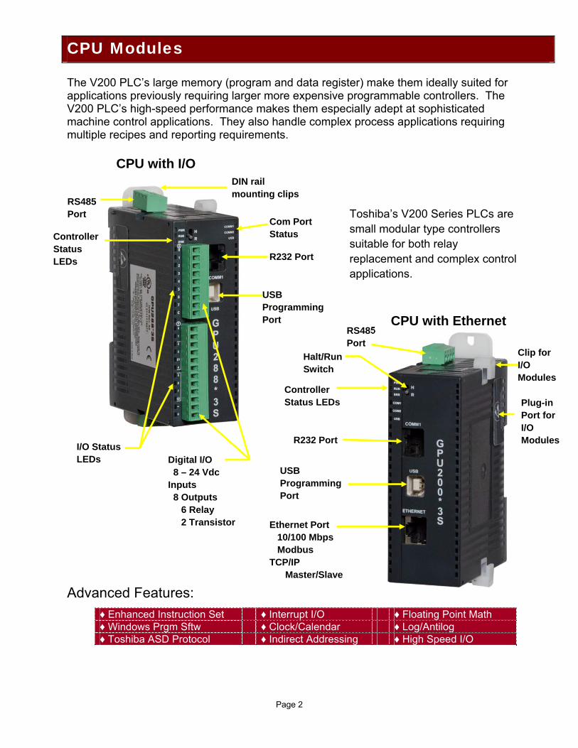
The V200 PLC’s large memory (program and data register) make them ideally suited for applications previously requiring larger more expensive programmable controllers. The V200 PLC’s high-speed performance makes them especially adept at sophisticated machine control applications. They also handle complex process applications requiring multiple recipes and reporting requirements. Advanced Features:
Micro Programmable Controllers
♦ Enhanced Instruction Set ♦ Interrupt I/O ♦ Floating Point Math ♦ Windows Prgm Sftw ♦ Clock/Calendar ♦ Log/Antilog ♦ Toshiba ASD Protocol ♦ Indirect Addressing ♦ High Speed I/O
CPU Modules
RS485 Port Toshiba’s V200 Series PLCs are
small modular type controllers suitable for both relay replacement and complex control applications.
CPU with I/O
CPU with Ethernet RS485 Port
R232 Port
USB Programming Port
Controller Status LEDs
I/O Status LEDs Digital I/O
8 – 24 Vdc Inputs 8 Outputs 6 Relay 2 Transistor Ethernet Port
10/100 Mbps Modbus TCP/IP Master/Slave
R232 Port
USB Programming Port
DIN rail mounting clips
Com Port Status Controller
Status LEDs
Clip for I/O Modules
Plug-in Port for I/O Modules
Halt/Run Switch
Plug-in Port for I/O Modules
Page 3
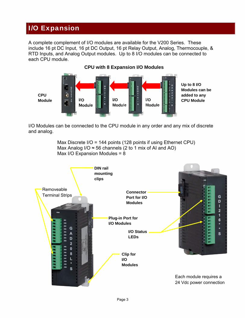
A complete complement of I/O modules are available for the V200 Series. These include 16 pt DC Input, 16 pt DC Output, 16 pt Relay Output, Analog, Thermocouple, & RTD Inputs, and Analog Output modules. Up to 8 I/O modules can be connected to each CPU module. I/O Modules can be connected to the CPU module in any order and any mix of discrete and analog.
Max Discrete I/O = 144 points (128 points if using Ethernet CPU) Max Analog I/O ≈ 56 channels (2 to 1 mix of AI and AO) Max I/O Expansion Modules = 8
I/O Expansion
CPU with 8 Expansion I/O Modules
Removeable Terminal Strips
DIN rail mounting clips
Each module requires a 24 Vdc power connection
Connector Port for I/O Modules
Plug-in Port for I/O Modules
I/O Status LEDs
Clip for I/O Modules
CPU Module I/O
Module I/O Module
I/O Module
Up to 8 I/O Modules can be added to any CPU Module
Page 4
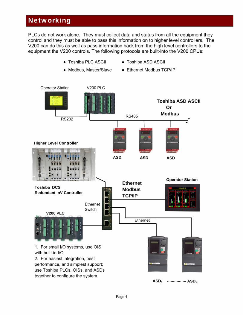
PLCs do not work alone. They must collect data and status from all the equipment they control and they must be able to pass this information on to higher level controllers. The V200 can do this as well as pass information back from the high level controllers to the equipment the V200 controls. The following protocols are built-into the V200 CPUs:
● Toshiba PLC ASCII ● Toshiba ASD ASCII
● Modbus, Master/Slave ● Ethernet Modbus TCP/IP
Networking Networking
Toshiba ASD ASCII Or Modbus
Operator Station V200 PLC
RS232RS485
Ethernet Modbus TCP/IP
Operator Station
Toshiba DCS Redundant nV Controller
Ethernet Switch
V200 PLC
Ethernet
ASD ASD ASD
ASD1 ASDN
1. For small I/O systems, use OIS with built-in I/O. 2. For easiest integration, best performance, and simplest support; use Toshiba PLCs, OISs, and ASDs together to configure the system.
Higher Level Controller
Page 5
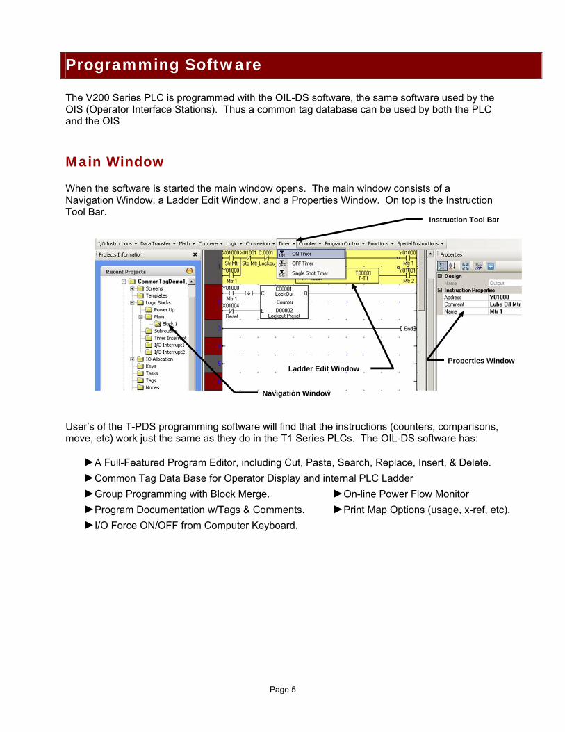
The V200 Series PLC is programmed with the OIL-DS software, the same software used by the OIS (Operator Interface Stations). Thus a common tag database can be used by both the PLC and the OIS
Main Window When the software is started the main window opens. The main window consists of a Navigation Window, a Ladder Edit Window, and a Properties Window. On top is the Instruction Tool Bar. User’s of the T-PDS programming software will find that the instructions (counters, comparisons, move, etc) work just the same as they do in the T1 Series PLCs. The OIL-DS software has:
►A Full-Featured Program Editor, including Cut, Paste, Search, Replace, Insert, & Delete.
►Common Tag Data Base for Operator Display and internal PLC Ladder
►Group Programming with Block Merge. ►On-line Power Flow Monitor
►Program Documentation w/Tags & Comments. ►Print Map Options (usage, x-ref, etc).
►I/O Force ON/OFF from Computer Keyboard.
Programming Software
Navigation Window
Ladder Edit Window Properties Window
Instruction Tool Bar
Page 6
Instruction Set Along with reliable hardware, solid software, and good peripherals; a comprehensive instruction set is also necessary. Toshiba’s many years of experience in machine control, process control, and motion control has resulted in a full featured instruction set for the V200 Series PLCs (the same as T1 Series). Instructions include: Standard Ladder Instructions:
NO, NC, & Transitional Contacts Coils, Timers, & Counters
Data Transfer Instructions MOV, Table Initialize, Table MOV Data Exchange, Multiplexer, Demultiplexer
Logical Instructions: AND, OR, Exclusive OR, Bit Test
Shift Instructions: 1 Bit Shift (right/left), n Bits Shift (right/left) Shift Register, Bi-directional Shift Register
Math Instructions: Single & Double Register Add, Subtract, Divide,& Multiply Increment, Decrement, Log & Antilog
Data Compare Instructions: Greater Than, Greater Than or Equal, Equal Less Than, Less Than or Equal, Not Equal
Data Conversion Instructions: Integer to Float, Float to Integer, Double Length to Float, Float to Double Length Integer, HEX to ASCII, ASCII to HEX, 2’s Complement Double Length 2’s Complement, 7-Segment Decode Conversion to ASCII/Binary/BCD
Program Control Instructions: Subroutine Call/Return, FOR/NEXT, Interrupt Enable/Disable, Interrupt Return Step Sequence Initialize/Input/Output, Master Control Set/Reset Jump Control Set/Reset
Special Process Instructions: Moving Average, Digital Filter, PID, Limit Upper/Lower, Max/Min/Avg Value, Function Generator, Special Module Read/Write
Note: For a complete list of all instructions and explanation of operation, please see help menu in the OIS-DS software.
Page 7
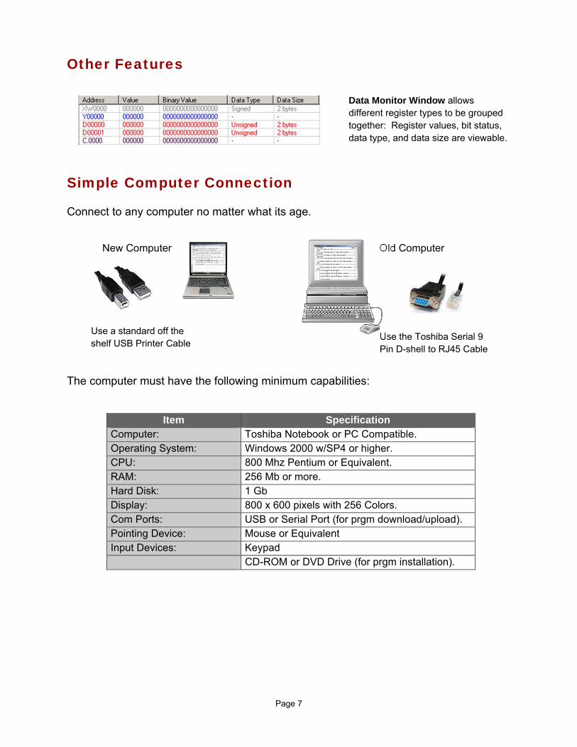
Other Features
Simple Computer Connection Connect to any computer no matter what its age. The computer must have the following minimum capabilities:
Item Specification Computer: Toshiba Notebook or PC Compatible. Operating System: Windows 2000 w/SP4 or higher. CPU: 800 Mhz Pentium or Equivalent. RAM: 256 Mb or more. Hard Disk: 1 Gb Display: 800 x 600 pixels with 256 Colors. Com Ports: USB or Serial Port (for prgm download/upload). Pointing Device: Mouse or Equivalent Input Devices: Keypad CD-ROM or DVD Drive (for prgm installation).
Old Computer
Use the Toshiba Serial 9 Pin D-shell to RJ45 Cable
New Computer
Use a standard off the shelf USB Printer Cable
Data Monitor Window allows different register types to be grouped together: Register values, bit status, data type, and data size are viewable.
Page 8
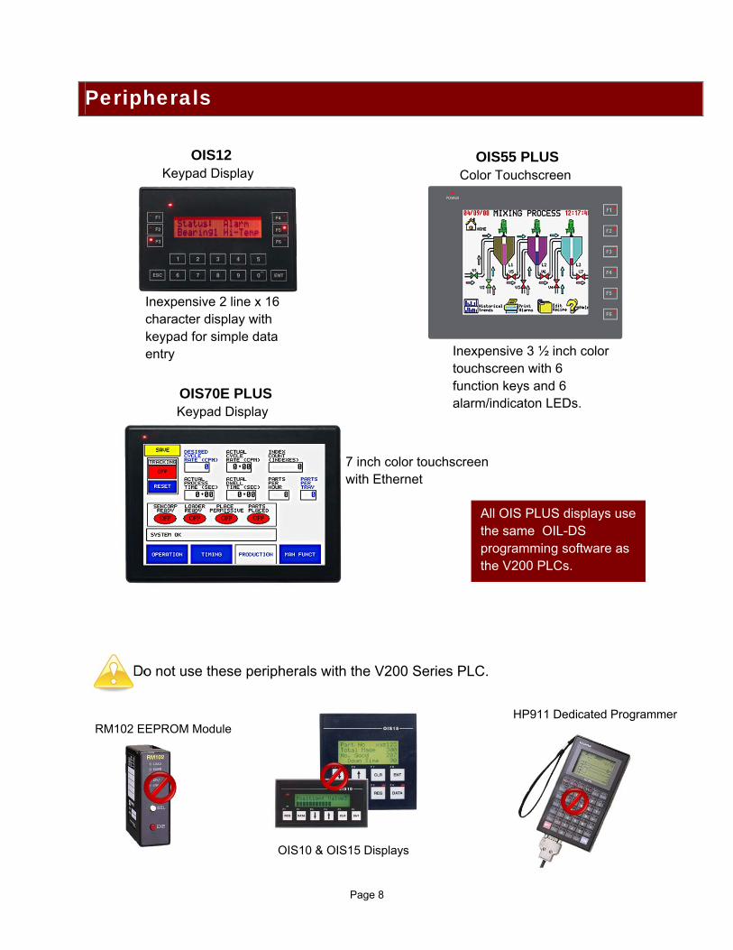
Do not use these peripherals with the V200 Series PLC.
Peripherals
RM102 EEPROM Module
OIS10 & OIS15 Displays
HP911 Dedicated Programmer
OIS12 Keypad Display
OIS55 PLUS Color Touchscreen
Inexpensive 2 line x 16 character display with keypad for simple data entry Inexpensive 3 ½ inch color
touchscreen with 6 function keys and 6 alarm/indicaton LEDs.
OIS70E PLUS Keypad Display
7 inch color touchscreen with Ethernet
All OIS PLUS displays use the same OIL-DS programming software as the V200 PLCs.
Page 9
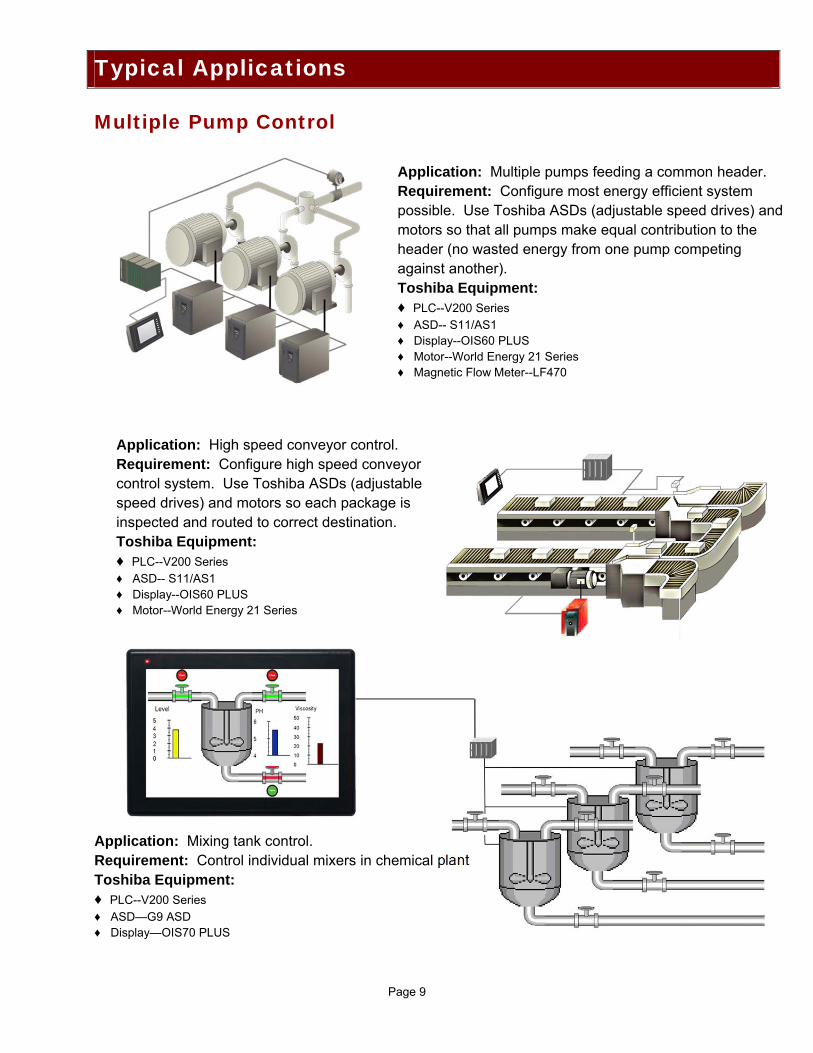
Multiple Pump Control Application: Mixing tank control. Requirement: Control individual mixers in chemical plant Toshiba Equipment: ♦ PLC--V200 Series
♦ ASD—G9 ASD ♦ Display—OIS70 PLUS
Typical Applications
Application: Multiple pumps feeding a common header. Requirement: Configure most energy efficient system possible. Use Toshiba ASDs (adjustable speed drives) and motors so that all pumps make equal contribution to the header (no wasted energy from one pump competing against another). Toshiba Equipment: ♦ PLC--V200 Series
♦ ASD-- S11/AS1 ♦ Display--OIS60 PLUS ♦ Motor--World Energy 21 Series ♦ Magnetic Flow Meter--LF470
Application: High speed conveyor control. Requirement: Configure high speed conveyor control system. Use Toshiba ASDs (adjustable speed drives) and motors so each package is inspected and routed to correct destination. Toshiba Equipment: ♦ PLC--V200 Series
♦ ASD-- S11/AS1 ♦ Display--OIS60 PLUS ♦ Motor--World Energy 21 Series
Page 10
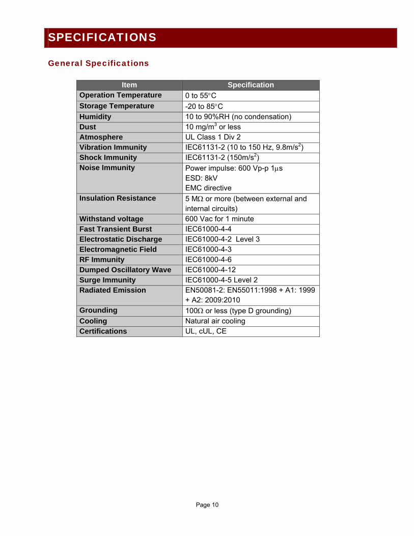
General Specifications
Item Specification Operation Temperature 0 to 55C Storage Temperature -20 to 85C Humidity 10 to 90%RH (no condensation) Dust 10 mg/m3 or less Atmosphere UL Class 1 Div 2 Vibration Immunity IEC61131-2 (10 to 150 Hz, 9.8m/s2) Shock Immunity IEC61131-2 (150m/s2) Noise Immunity Power impulse: 600 Vp-p 1s
ESD: 8kV EMC directive
Insulation Resistance 5 M or more (between external and internal circuits)
Withstand voltage 600 Vac for 1 minute Fast Transient Burst IEC61000-4-4 Electrostatic Discharge IEC61000-4-2 Level 3 Electromagnetic Field IEC61000-4-3 RF Immunity IEC61000-4-6 Dumped Oscillatory Wave IEC61000-4-12 Surge Immunity IEC61000-4-5 Level 2 Radiated Emission EN50081-2: EN55011:1998 + A1: 1999
+ A2: 2009:2010 Grounding 100 or less (type D grounding) Cooling Natural air cooling Certifications UL, cUL, CE
SPECIFICATIONS
Page 11
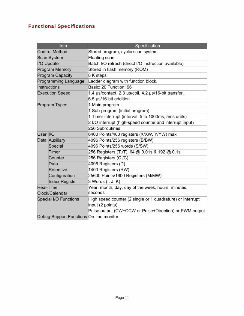
Functional Specifications
Item Specification Control Method Stored program, cyclic scan system Scan System Floating scan I/O Update Batch I/O refresh (direct I/O instruction available) Program Memory Stored in flash memory (ROM) Program Capacity 8 K steps Programming Language Ladder diagram with function block. Instructions Basic: 20 Function: 96 Execution Speed 1.4 µs/contact, 2.3 µs/coil, 4.2 µs/16-bit transfer,
6.5 µs/16-bit addition Program Types 1 Main program
1 Sub-program (initial program) 1 Timer interrupt (interval: 5 to 1000ms, 5ms units) 2 I/O interrupt (high-speed counter and interrupt input) 256 Subroutines
User Data
I/O 6400 Points/400 registers (X/XW, Y/YW) max Auxiliary 4096 Points/256 registers (B/BW) Special 4096 Points/256 words (S/SW) Timer 256 Registers (T./T), 64 @ 0.01s & 192 @ 0.1s Counter 256 Registers (C./C) Data 4096 Registers (D) Retentive 1400 Registers (RW) Configuration 25600 Points/1600 Registers (M/MW) Index Register 3 Words (I, J, K)
Real-Time Clock/Calendar
Year, month, day, day of the week, hours, minutes, seconds
Special I/O Functions High speed counter (2 single or 1 quadrature) or Interrupt input (2 points), Pulse output (CW+CCW or Pulse+Direction) or PWM output
Debug Support Functions On-line monitor
Page 12
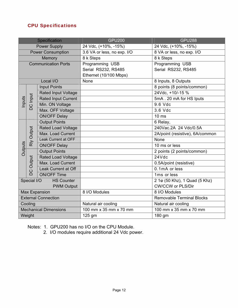
CPU Specifications
Notes: 1. GPU200 has no I/O on the CPU Module.
2. I/O modules require additional 24 Vdc power.
Specification GPU200 GPU288 Power Supply 24 Vdc, (+10%, -15%) 24 Vdc, (+10%, -15%)
Power Consumption 3.6 VA or less, no exp. I/O 8 VA or less, no exp. I/O Memory 8 k Steps 8 k Steps
Communication Ports
Programming USB Serial RS232, RS485 Ethernet (10/100 Mbps)
Programming USB Serial RS232, RS485
Local I/O None 8 Inputs, 8 Outputs
Inpu
ts
DC
Inpu
t
Input Points 8 points (8 points/common) Rated Input Voltage 24Vdc, +10/-15 % Rated Input Current 5mA . 20 mA for HS Iputs Min. ON Voltage 9.6 Vdc Max. OFF Voltage 3.6 Vdc ON/OFF Delay 10 ms
Out
puts
Rly
Out
put
Output Points 6 Relay, Rated Load Voltage 240Vac.2A 24 Vdc/0.5A Max. Load Current 2A/point (resistive), 6A/common Leak Current at OFF None ON/OFF Delay 10 ms or less
DC
Out
put
Output Points 2 points (2 points/common) Rated Load Voltage 24Vdc Max. Load Current 0.5A/point (resistive) Leak Current at Off 0.1mA or less ON/OFF Time 1ms or less
Special I/O HS Counter PWM Output
2 1ⱷ (50 Khz), 1 Quad (5 Khz) CW/CCW or PLS/Dir
Max Expansion 8 I/O Modules 8 I/O Modules External Connection Removable Terminal Blocks Cooling Natural air cooling Natural air cooling Mechanical Dimensions 100 mm x 35 mm x 70 mm 100 mm x 35 mm x 70 mm Weight 125 gm 180 gm
Page 13
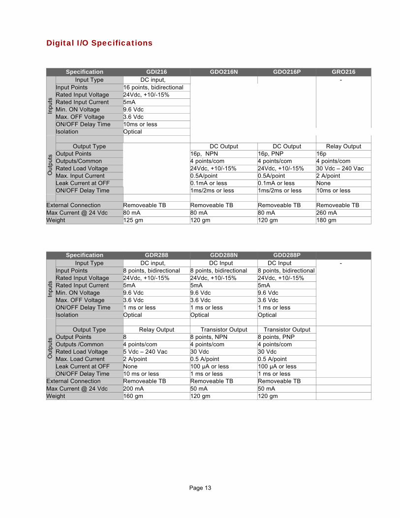
Digital I/O Specifications
Specification GDI216 GDO216N GDO216P GRO216
Inp
uts
Input Type DC input, - Input Points 16 points, bidirectional Rated Input Voltage 24Vdc, +10/-15% Rated Input Current 5mA Min. ON Voltage 9.6 Vdc Max. OFF Voltage 3.6 Vdc ON/OFF Delay Time 10ms or less Isolation Optical
Ou
tpu
ts
Output Type DC Output DC Output Relay Output
Output Points 16p, NPN 16p, PNP 16p Outputs/Common 4 points/com 4 points/com 4 points/com Rated Load Voltage 24Vdc, +10/-15% 24Vdc, +10/-15% 30 Vdc – 240 Vac Max. Input Current 0.5A/point 0.5A/point 2 A/point Leak Current at OFF 0.1mA or less 0.1mA or less None ON/OFF Delay Time 1ms/2ms or less 1ms/2ms or less 10ms or less
External Connection Removeable TB Removeable TB Removeable TB Removeable TB Max Current @ 24 Vdc 80 mA 80 mA 80 mA 260 mA Weight 125 gm 120 gm 120 gm 180 gm
Specification GDR288 GDD288N GDD288P
Inp
uts
Input Type DC input, DC Input DC Input - Input Points 8 points, bidirectional 8 points, bidirectional 8 points, bidirectional Rated Input Voltage 24Vdc, +10/-15% 24Vdc, +10/-15% 24Vdc, +10/-15% Rated Input Current 5mA 5mA 5mA Min. ON Voltage 9.6 Vdc 9.6 Vdc 9.6 Vdc Max. OFF Voltage 3.6 Vdc 3.6 Vdc 3.6 Vdc ON/OFF Delay Time 1 ms or less 1 ms or less 1 ms or less Isolation Optical Optical Optical
Ou
tpu
ts
Output Type Relay Output Transistor Output Transistor Output
Output Points 8 8 points, NPN 8 points, PNP Outputs /Common 4 points/com 4 points/com 4 points/com Rated Load Voltage 5 Vdc – 240 Vac 30 Vdc 30 Vdc Max. Load Current 2 A/point 0.5 A/point 0.5 A/point Leak Current at OFF None 100 µA or less 100 µA or less ON/OFF Delay Time 10 ms or less 1 ms or less 1 ms or less
External Connection Removeable TB Removeable TB Removeable TB Max Current @ 24 Vdc 200 mA 50 mA 50 mA Weight 160 gm 120 gm 120 gm
Page 14
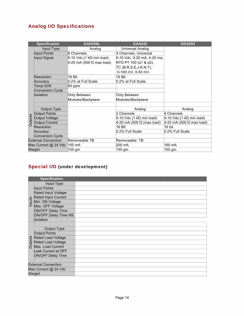
Analog I/O Specifications
Special I/O (under development)
Specification GAD208L GAA242 GDA204
Input Type Analog Universal Analog Input Points 8 Channels, 4 Channels, Universal Input Signal 0-10 Vdc,(1 kΏ min load)
4-20 mA (500 Ώ max load) 0-10 Vdc, 0-20 mA, 4-20 ma, RTD PT 100 (α1 & α2), TC (B,R,S,E,J,K,N,T), 0-100 mV, 0-50 mV.
Resolution 16 Bit 16 Bit Accuracy 0.2% at Full Scale 0.2% at Full Scale Temp Drift 60 ppm Conversion Cycle Isolation Only Between
Modules/Backplane Only Between Modules/Backplane
Ou
tpu
ts
Output Type Analog Analog
Output Points 2 Channels 4 Channels Output Voltage 0-10 Vdc (1 kΏ min load) 0-10 Vdc,(1 kΏ min load) Output Current 4-20 mA (500 Ώ (max load) 4-20 mA (500 Ώ max load) Resolution 16 Bit 16 bit Accuracy 0.2% Full Scale 0.2% Full Scale Conversion Cycle
External Connection Removeable TB Removeable TBMax Current @ 24 Vdc 150 mA 200 mA 160 mA Weight 155 gm 155 gm 155 gm
Specification
Inp
uts
Input Type Input Points Rated Input Voltage Rated Input Current Min. ON Voltage Max. OFF Voltage ON/OFF Delay Time ON/OFF Delay Time HS Isolation
Ou
tpu
ts
Output Type
Output Points Rated Load Voltage Rated Load Voltage Max. Load Current Leak Current at OFF ON/OFF Delay Time
External Connection Max Current @ 24 Vdc Weight
Page 15
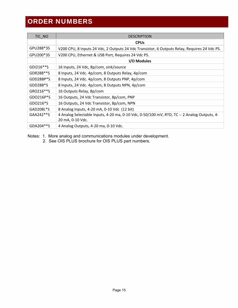
TIC_NO DESCRIPTION
CPUs
GPU288*3S V200 CPU, 8 Inputs 24 Vdc, 2 Outputs 24 Vdc Transistor, 6 Outputs Relay, Requires 24 Vdc PS.
GPU200*3S V200 CPU, Ethernet & USB Port, Requires 24 Vdc PS.
I/O Modules
GDI216**S 16 Inputs, 24 Vdc, 8p/com, sink/source
GDR288**S 8 Inputs, 24 Vdc. 4p/com, 8 Outputs Relay, 4p/com
GDD288P*S 8 Inputs, 24 Vdc. 4p/com, 8 Outputs PNP, 4p/com
GDD288*S 8 Inputs, 24 Vdc. 4p/com, 8 Outputs NPN, 4p/com
GRO216**S 16 Outputs Relay, 8p/com
GDO216P*S 16 Outputs, 24 Vdc Transistor, 8p/com, PNP
GDO216*S 16 Outputs, 24 Vdc Transistor, 8p/com, NPN
GAD208L*S 8 Analog Inputs, 4‐20 mA, 0‐10 Vdc (12 bit)
GAA242**S 4 Analog Selectable Inputs, 4‐20 ma, 0‐10 Vdc, 0‐50/100 mV, RTD, TC ‐‐ 2 Analog Outputs, 4‐20 mA, 0‐10 Vdc.
GDA204**S 4 Analog Outputs, 4‐20 ma, 0‐10 Vdc. Notes: 1. More analog and communications modules under development.
2. See OIS PLUS brochure for OIS PLUS part numbers.
ORDER NUMBERS

Rev 111010