Embed Size (px)
Citation preview

Dean, a member of the Commercial Food Equipment Service Association, recommends usingCFESA Certified Technicians.
Price: $6.0024-Hour Service Hotline 1-800-551-8633
819-574510-01
Micro-Flo B
uilt-In Series FiltrationSystem
sInstallation, O
peration & M
aintenance Manual
Models MF90-12BI, -14BI, -18BI & -20BI
i
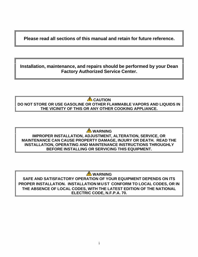
Please read all sections of this manual and retain for future reference.
Installation, maintenance, and repairs should be performed by your DeanFactory Authorized Service Center.
CAUTIONDO NOT STORE OR USE GASOLINE OR OTHER FLAMMABLE VAPORS AND LIQUIDS IN
THE VICINITY OF THIS OR ANY OTHER COOKING APPLIANCE.
WARNINGIMPROPER INSTALLATION, ADJUSTMENT, ALTERATION, SERVICE, OR
MAINTENANCE CAN CAUSE PROPERTY DAMAGE, INJURY OR DEATH. READ THEINSTALLATION, OPERATING AND MAINTENANCE INSTRUCTIONS THROUGHLY
BEFORE INSTALLING OR SERVICING THIS EQUIPMENT.
WARNINGSAFE AND SATISFACTORY OPERATION OF YOUR EQUIPMENT DEPENDS ON ITS
PROPER INSTALLATION. INSTALLATION MUST CONFORM TO LOCAL CODES, OR INTHE ABSENCE OF LOCAL CODES, WITH THE LATEST EDITION OF THE NATIONAL
ELECTRIC CODE, N.F.P.A. 70.
ii
Micro-Flo Series Built-In Filters
TABLE OF CONTENTS
Page #
1. DESCRIPTION AND SPECIFICATIONS 1-1
2. PRE-INSTALLATION 2-1
3. RECEIVING & INSTALLING THE FILTER 3-1
4. OPERATIONS 4-1
5. CLEANING AND MAINTENANCE 5-1
6. TROUBLESHOOTING 6-1
7. FACTORY SERVICE AND PARTS ORDERING 7-1
1-1
MICRO-FLO BUILT-IN SERIES FILTRATION SYSTEMSCHAPTER 1: DESCRIPTION AND SPECIFICATIONS
Micro-Flo Built-In Series filtration systems are available in sizes to handle quantities of oil up to 120pounds. They can be fabricated to match Dean gas (Super Marathon & Decathlon) or electric fryers(Cool Zone & Flatbottom Series), or in stand-alone cabinets. Micro-Flo filtration systemsincorporate a "gravity drain" design. The oil return line can be configured overhead (prior to 1994),internally plumbed, or returned by the hose & nozzle.
Prior to 1994, handle-operated ball valves or optional "push-pull" linkage-operated ball valvecontrols located in the filter cabinet were available. Current systems are configured with the oil-return and drain valve controls located in each fryer cabinet.
1.1 Construction
Micro-Flo Built-In filters are constructed with the following features:
ø Fully welded, heavy gauge steel, with a removable stainless steel filter pan.
ø Internal oil return lines are plumbed with either a "push-pull" valve system in the filtercabinet or manual drain valves at each fryer.
ø A 1/3 HP motor, coupled with a 5 GPM pump returns filtered oil to the fry vessel. An 8GPM pump (optional) is also available.
1.2 Operating Controls
Micro-Flo Built-In filters are equipped with the following operating controls:
ø The "ON-OFF" power switch is mounted on the front control panel of the filter cabinet. Ifthe filter is equipped with an optional heater, a three-position switch (Heater/Off/Pump) isincluded as the power switch.
ø Individual fryer drain valves control which fryer is filtered, reducing operator error.
ø Prior to 1994: Oil-return valves are either "push-pull" controls or "lever-operated" manualball valves; the push-pull controls are in the filter cabinet and the "lever-operated" valves areat each individual fryer.
ø 1994 and later: Oil-return valves are push-pull controls, located within each individual fryercabinet. A manual "hose-disconnect" valve is located in the filter cabinet.
2-1
MICRO-FLO BUILT-IN SERIES FILTRATION SYSTEMSCHAPTER 2: PRE-INSTALLATION
2.1 General
Micro-Flo Built-In filters are compatible with the following fryer models:
Cool Zone Fryers: Super Marathon and Decathlon Gas FryersFlatbottom Fryers: 1824G and 2424G (gas); 1824E and 2424E (electric)Electric Fryers: 714E, 1414E, 1818E, 2020E and 18UE
2.2 Standards
Installation must be planned in accordance with all applicable state and local codes.
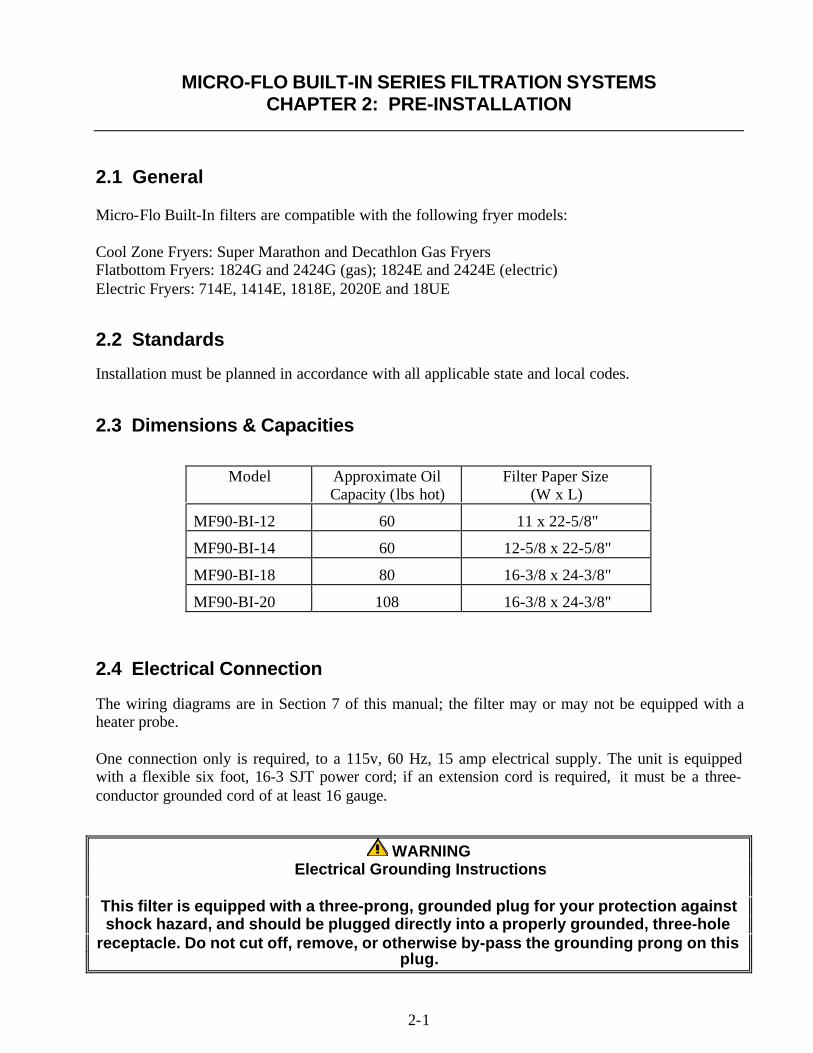
2.3 Dimensions & Capacities
Model Approximate OilCapacity (lbs hot)
Filter Paper Size(W x L)
MF90-BI-12 60 11 x 22-5/8"
MF90-BI-14 60 12-5/8 x 22-5/8"
MF90-BI-18 80 16-3/8 x 24-3/8"
MF90-BI-20 108 16-3/8 x 24-3/8"
2.4 Electrical Connection
The wiring diagrams are in Section 7 of this manual; the filter may or may not be equipped with aheater probe.
One connection only is required, to a 115v, 60 Hz, 15 amp electrical supply. The unit is equippedwith a flexible six foot, 16-3 SJT power cord; if an extension cord is required, it must be a three-conductor grounded cord of at least 16 gauge.
WARNING Electrical Grounding Instructions
This filter is equipped with a three-prong, grounded plug for your protection againstshock hazard, and should be plugged directly into a properly grounded, three-hole
receptacle. Do not cut off, remove, or otherwise by-pass the grounding prong on thisplug.
3-1
MICRO-FLO BUILT-IN SERIES FILTRATION SYSTEMSCHAPTER 3: RECEIVING & INSTALLING THE FILTER
3.1 General
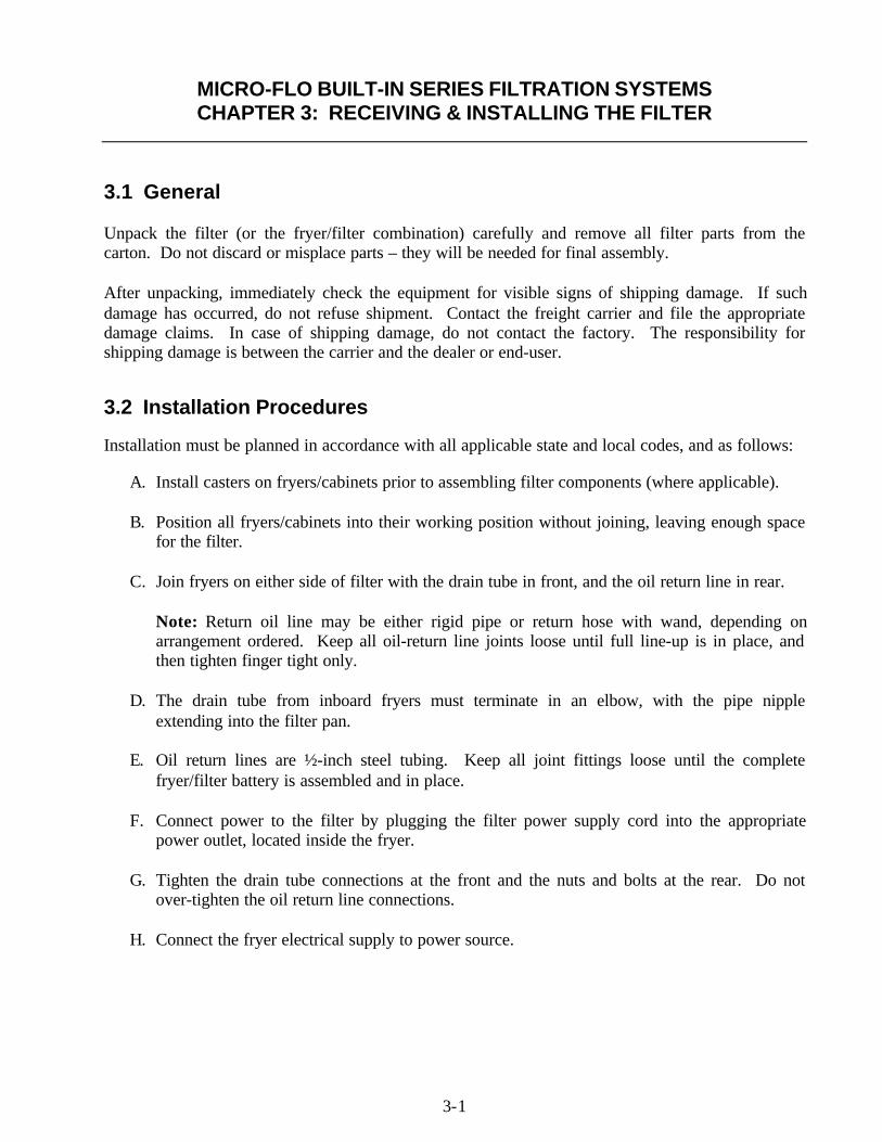
Unpack the filter (or the fryer/filter combination) carefully and remove all filter parts from thecarton. Do not discard or misplace parts – they will be needed for final assembly.
After unpacking, immediately check the equipment for visible signs of shipping damage. If suchdamage has occurred, do not refuse shipment. Contact the freight carrier and file the appropriatedamage claims. In case of shipping damage, do not contact the factory. The responsibility forshipping damage is between the carrier and the dealer or end-user.
3.2 Installation Procedures
Installation must be planned in accordance with all applicable state and local codes, and as follows:
A. Install casters on fryers/cabinets prior to assembling filter components (where applicable).
B. Position all fryers/cabinets into their working position without joining, leaving enough spacefor the filter.
C. Join fryers on either side of filter with the drain tube in front, and the oil return line in rear.
Note: Return oil line may be either rigid pipe or return hose with wand, depending onarrangement ordered. Keep all oil-return line joints loose until full line-up is in place, andthen tighten finger tight only.
D. The drain tube from inboard fryers must terminate in an elbow, with the pipe nippleextending into the filter pan.
E. Oil return lines are ½-inch steel tubing. Keep all joint fittings loose until the completefryer/filter battery is assembled and in place.
F. Connect power to the filter by plugging the filter power supply cord into the appropriatepower outlet, located inside the fryer.
G. Tighten the drain tube connections at the front and the nuts and bolts at the rear. Do notover-tighten the oil return line connections.
H. Connect the fryer electrical supply to power source.
4-1
MICRO-FLO BUILT-IN SERIES FILTRATION SYSTEMSCHAPTER 4: OPERATIONS
4.1 Initial Installation
On initial installation and before each use, remove all loose parts from the filter, wash the filter panand all accessories in hot, soapy water and dry thoroughly.
4.2 Assembling The Filter Pack
4.2.1 Models Prior to 1994
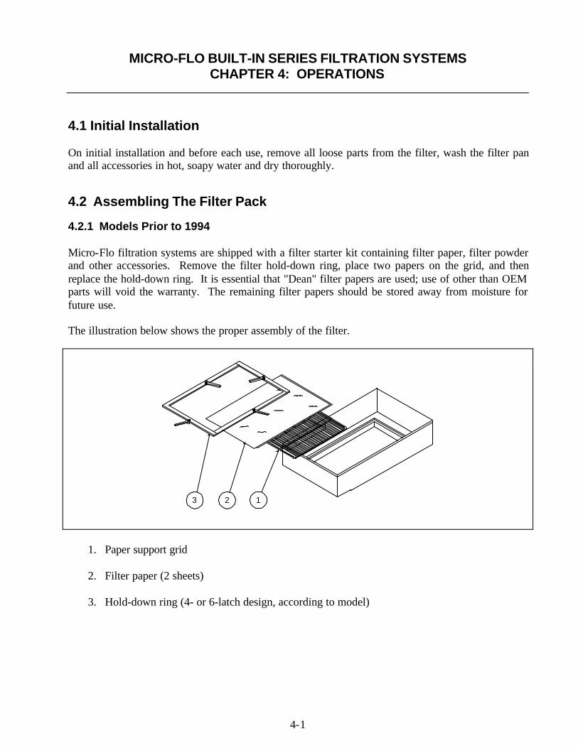
Micro-Flo filtration systems are shipped with a filter starter kit containing filter paper, filter powderand other accessories. Remove the filter hold-down ring, place two papers on the grid, and thenreplace the hold-down ring. It is essential that "Dean" filter papers are used; use of other than OEMparts will void the warranty. The remaining filter papers should be stored away from moisture forfuture use.
The illustration below shows the proper assembly of the filter.
123
1. Paper support grid
2. Filter paper (2 sheets)
3. Hold-down ring (4- or 6-latch design, according to model)
4-2
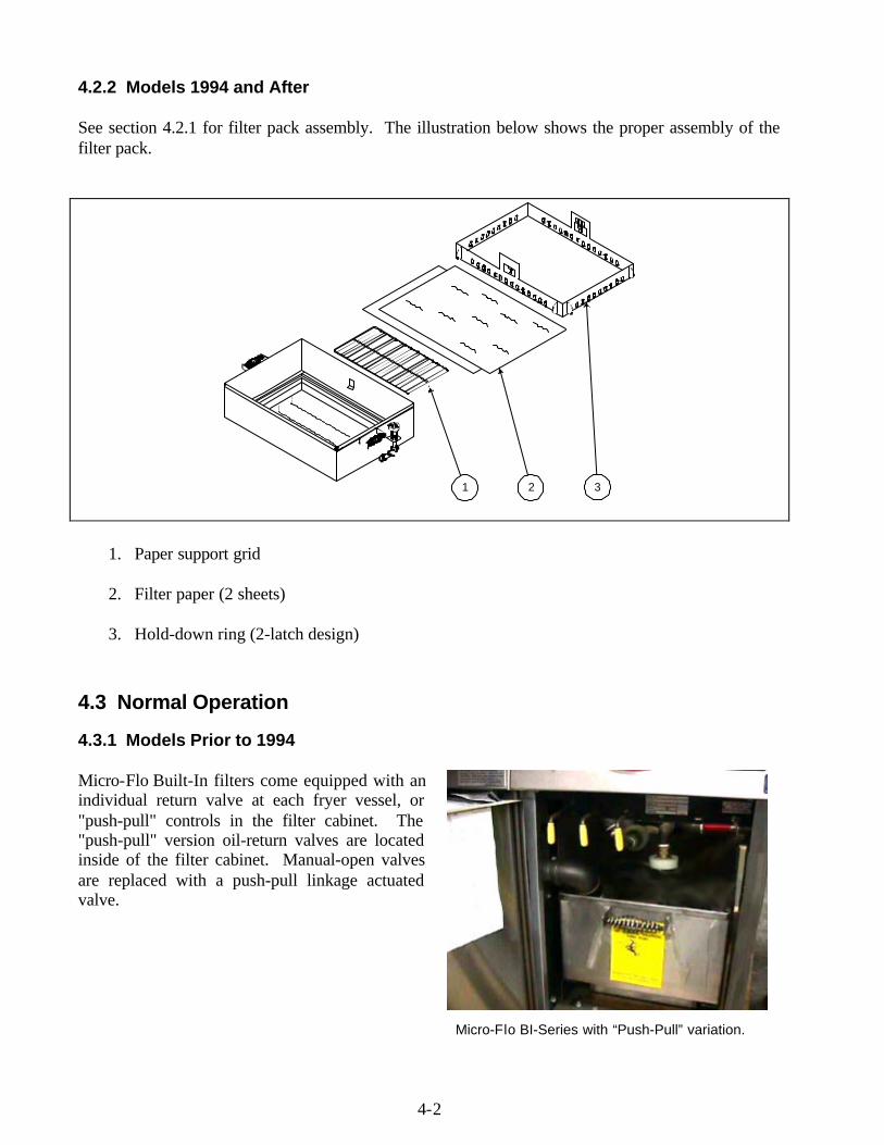
4.2.2 Models 1994 and After
See section 4.2.1 for filter pack assembly. The illustration below shows the proper assembly of thefilter pack.
1 2 3
1. Paper support grid
2. Filter paper (2 sheets)
3. Hold-down ring (2-latch design)
4.3 Normal Operation
4.3.1 Models Prior to 1994
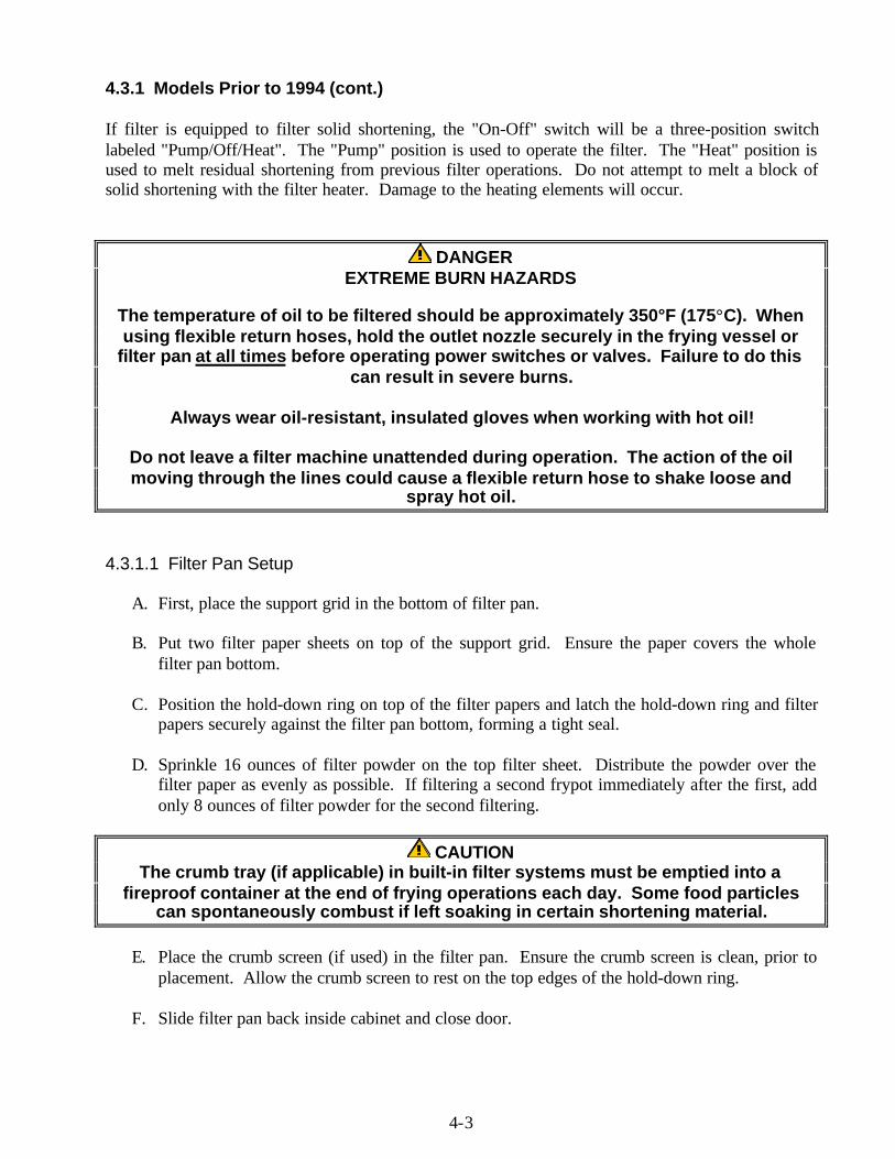
Micro-Flo Built-In filters come equipped with anindividual return valve at each fryer vessel, or"push-pull" controls in the filter cabinet. The"push-pull" version oil-return valves are locatedinside of the filter cabinet. Manual-open valvesare replaced with a push-pull linkage actuatedvalve.
Micro-Flo BI-Series with “Push-Pull” variation.
4-3
4.3.1 Models Prior to 1994 (cont.)
If filter is equipped to filter solid shortening, the "On-Off" switch will be a three-position switchlabeled "Pump/Off/Heat". The "Pump" position is used to operate the filter. The "Heat" position isused to melt residual shortening from previous filter operations. Do not attempt to melt a block ofsolid shortening with the filter heater. Damage to the heating elements will occur.
DANGEREXTREME BURN HAZARDS
The temperature of oil to be filtered should be approximately 350°F (175°C). Whenusing flexible return hoses, hold the outlet nozzle securely in the frying vessel or
filter pan at all times before operating power switches or valves. Failure to do thiscan result in severe burns.
Always wear oil-resistant, insulated gloves when working with hot oil!
Do not leave a filter machine unattended during operation. The action of the oilmoving through the lines could cause a flexible return hose to shake loose and
spray hot oil.
4.3.1.1 Filter Pan Setup
A. First, place the support grid in the bottom of filter pan.
B. Put two filter paper sheets on top of the support grid. Ensure the paper covers the wholefilter pan bottom.
C. Position the hold-down ring on top of the filter papers and latch the hold-down ring and filterpapers securely against the filter pan bottom, forming a tight seal.
D. Sprinkle 16 ounces of filter powder on the top filter sheet. Distribute the powder over thefilter paper as evenly as possible. If filtering a second frypot immediately after the first, addonly 8 ounces of filter powder for the second filtering.
CAUTIONThe crumb tray (if applicable) in built-in filter systems must be emptied into a
fireproof container at the end of frying operations each day. Some food particlescan spontaneously combust if left soaking in certain shortening material.
E. Place the crumb screen (if used) in the filter pan. Ensure the crumb screen is clean, prior toplacement. Allow the crumb screen to rest on the top edges of the hold-down ring.
F. Slide filter pan back inside cabinet and close door.
4-4
4.3.1.2 Filter Operation
A. Turn fryer "OFF".
B. Filter one fryer at a time.
C. Remove fry-baskets, crumb screen and/or drop-in grid from fryer.
D. Stir the oil below the heat transfer tubes or electric elements with an "L" shaped Teflon brush(included with accessory pack) to loosen sediment.
E. Open the drain valve at the fryer and continue to stir and brush down the sides of the vesseland tubes or electric elements.
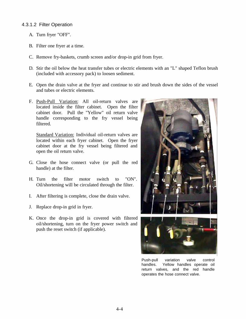
F. Push-Pull Variation: All oil-return valves arelocated inside the filter cabinet. Open the filtercabinet door. Pull the "Yellow" oil return valvehandle corresponding to the fry vessel beingfiltered.
Standard Variation: Individual oil-return valves arelocated within each fryer cabinet. Open the fryercabinet door at the fry vessel being filtered andopen the oil return valve.
G. Close the hose connect valve (or pull the redhandle) at the filter.
H. Turn the filter motor switch to "ON".Oil/shortening will be circulated through the filter.
I. After filtering is complete, close the drain valve.
J. Replace drop-in grid in fryer.
K. Once the drop-in grid is covered with filteredoil/shortening, turn on the fryer power switch andpush the reset switch (if applicable).
Push-pull variation valve controlhandles. Yellow handles operate oilreturn valves, and the red handleoperates the hose connect valve.
4-5
4.3.1.2 Filter Operation (cont.)
L. Allow the filter to pump bubbles into the fryer for 15-20 seconds to ensure evacuation of alloil/shortening from the filter pan and return lines.
M. Turn the filter switch to "OFF".
N. Close the oil return valve (or push yellow handle) to the fryer being filtered.
NOTE: The filtering cycle for one fryer is complete. To filter additional fryers, repeat theabove steps, starting with item "A". Complete the process with the following final step.
CAUTIONWhen the filter pump is "ON", NEVER open the hose connect valve without the
optional flexible hose connected. Always ensure that the optional flexible hose isproperly connected and the hose wand is firmly held in the filter pan or fry vessel
prior to opening the hose connect valve. Failure to do this increases the chance ofburn injury from spraying hot oil/shortening.
O. Open the hose connect valve (or push red handle) at the filter and close the filter cabinetdoor.
NOTEWith the hose connect valve "open", any oil left in the return lines will drain into the filterpan. With the return valve "closed", no oil will back-flush from the frying vessel, into thelines. When not filtering, leave the hose connect valve "open", and the oil-return valve"closed".
4.3.1.3 Changing Filter Paper
The top piece of filter paper should be discarded when it becomes dark or scuffed in appearance.Follow the procedure below and refer to the illustration on page 4-1.
A. Prior to changing the paper, use the optional flexible hose with about one-inch of oil in thefilter pan or oil drawn from the fryer to flush all debris from the filter pan sides onto thepaper.
B. Return all oil to the fryer.
C. Open the locking latches of the hold-down ring (see Item #3, page 4-1) and lift the ring out ofthe filter tank.
D. Roll both ends of the used (top) sheet of paper in to the center, ensuring no sediment fallsout. Discard top filter paper.
E. Remove the second sheet of paper and set aside for later use.
4-6
4.3.1.3 Changing Filter Paper (cont.)
F. Remove and check the grid for cleanliness and clean if necessary.
G. Inspect the filter pan for cleanliness and clean if necessary; also inspect the oil-pickup tube atthe rear of the pan for obstructions or solidified shortening.
H. Replace the bottom grid, place a new sheet of filter paper on the grid, and place the oldbottom sheet on top of the new piece. Use only filter paper approved for the filtrationsystem. Failure to do so will increase the likelihood of system malfunction.
I. Replace the hold-down ring.
4.3.2 Models 1994 and After
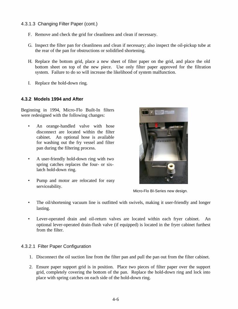
Beginning in 1994, Micro-Flo Built-In filterswere redesigned with the following changes:
• An orange-handled valve with hosedisconnect are located within the filtercabinet. An optional hose is availablefor washing out the fry vessel and filterpan during the filtering process.
• A user-friendly hold-down ring with twospring catches replaces the four- or six-latch hold-down ring.
• Pump and motor are relocated for easyserviceability.
• The oil/shortening vacuum line is outfitted with swivels, making it user-friendly and longerlasting.
• Lever-operated drain and oil-return valves are located within each fryer cabinet. Anoptional lever-operated drain-flush valve (if equipped) is located in the fryer cabinet furthestfrom the filter.
4.3.2.1 Filter Paper Configuration
1. Disconnect the oil suction line from the filter pan and pull the pan out from the filter cabinet.
2. Ensure paper support grid is in position. Place two pieces of filter paper over the supportgrid, completely covering the bottom of the pan. Replace the hold-down ring and lock intoplace with spring catches on each side of the hold-down ring.
Micro-Flo BI-Series new design.
4-7
4.3.2.1 Filter Paper Configuration (cont.)
3. Sprinkle 16 ounces of filter powder evenly over the filter paper. Return the filter pan tofilter cabinet, ensuring that the drainpipe outlets are directly over filter pan. If filtering asecond frypot immediately after the first, add only 8 ounces of filter powder for the secondfiltering.
4. Reconnect the oil-suction line to filter pan and snap into place. Ensure the quick-disconnectfitting is properly connected by pulling up on the male assembly while snapping into place.
5. Close cabinet door. Filter is ready for operation.
4.3.2.2 Filter Operation
1. Ensure that the power switch or operating thermostat dial is in the "OFF" position.
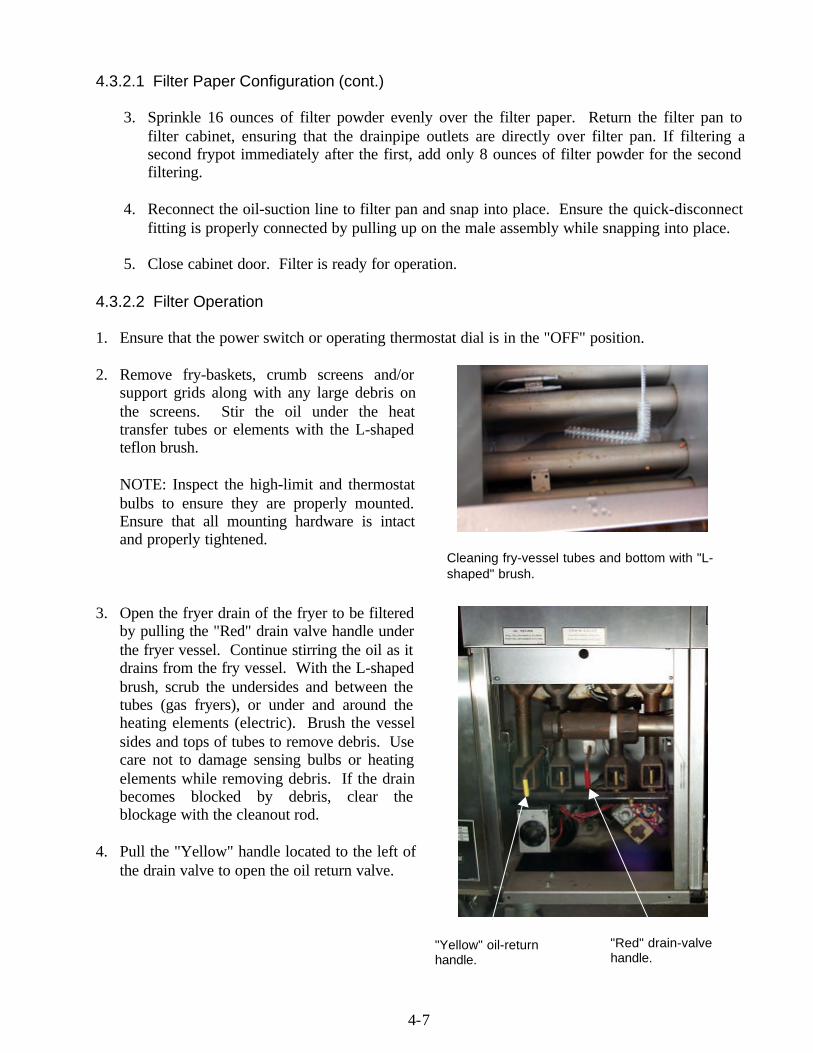
2. Remove fry-baskets, crumb screens and/orsupport grids along with any large debris onthe screens. Stir the oil under the heattransfer tubes or elements with the L-shapedteflon brush.
NOTE: Inspect the high-limit and thermostatbulbs to ensure they are properly mounted.Ensure that all mounting hardware is intactand properly tightened.
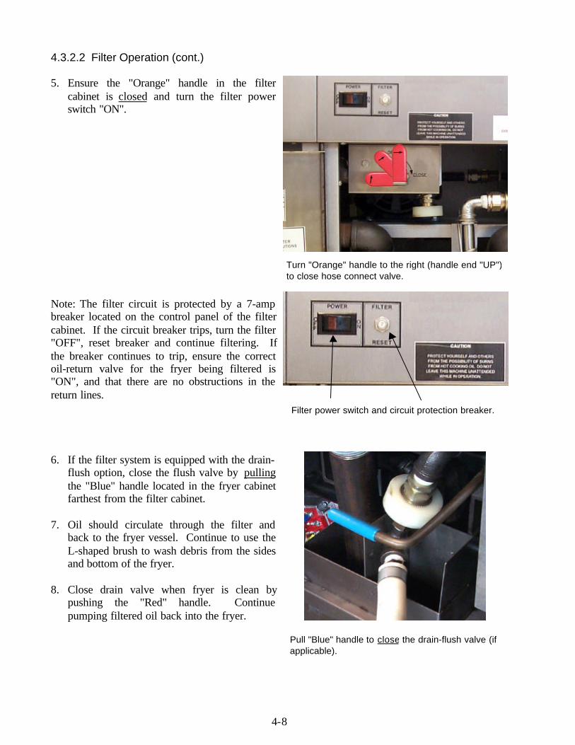
3. Open the fryer drain of the fryer to be filteredby pulling the "Red" drain valve handle underthe fryer vessel. Continue stirring the oil as itdrains from the fry vessel. With the L-shapedbrush, scrub the undersides and between thetubes (gas fryers), or under and around theheating elements (electric). Brush the vesselsides and tops of tubes to remove debris. Usecare not to damage sensing bulbs or heatingelements while removing debris. If the drainbecomes blocked by debris, clear theblockage with the cleanout rod.
4. Pull the "Yellow" handle located to the left ofthe drain valve to open the oil return valve.
Cleaning fry-vessel tubes and bottom with "L-shaped" brush.
"Yellow" oil-returnhandle.
"Red" drain-valvehandle.
4-8
4.3.2.2 Filter Operation (cont.)
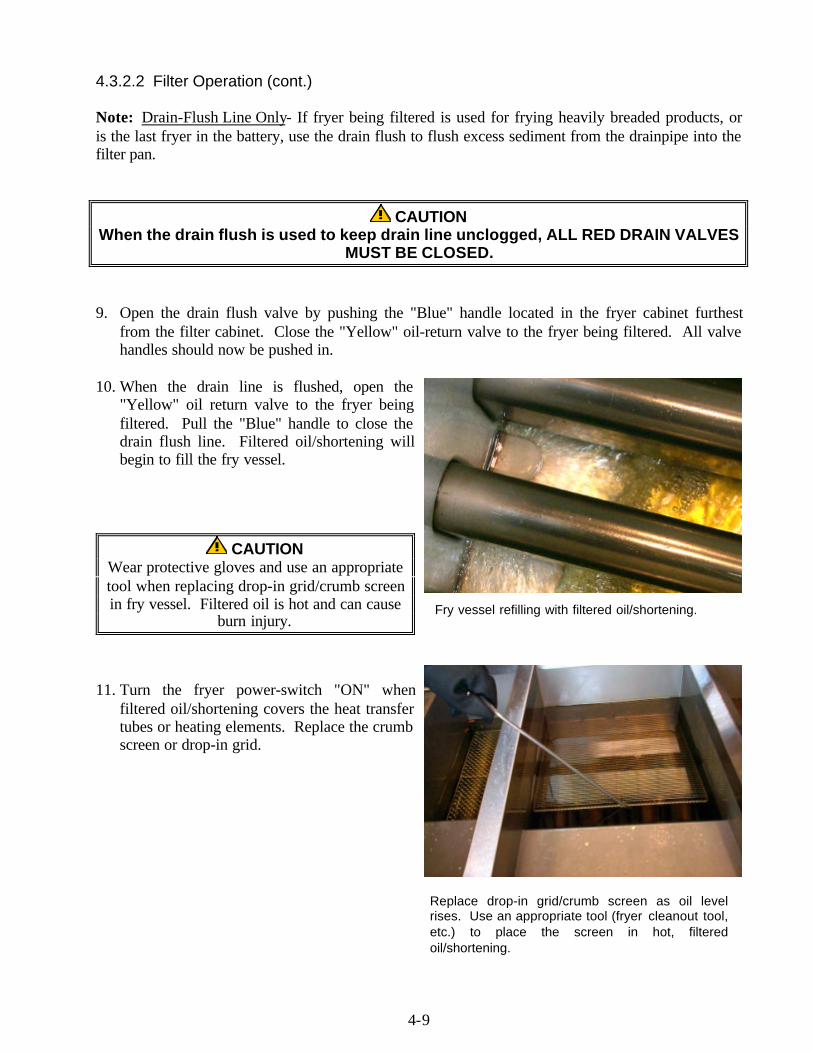
5. Ensure the "Orange" handle in the filtercabinet is closed and turn the filter powerswitch "ON".
Note: The filter circuit is protected by a 7-ampbreaker located on the control panel of the filtercabinet. If the circuit breaker trips, turn the filter"OFF", reset breaker and continue filtering. Ifthe breaker continues to trip, ensure the correctoil-return valve for the fryer being filtered is"ON", and that there are no obstructions in thereturn lines.
6. If the filter system is equipped with the drain-flush option, close the flush valve by pullingthe "Blue" handle located in the fryer cabinetfarthest from the filter cabinet.
7. Oil should circulate through the filter andback to the fryer vessel. Continue to use theL-shaped brush to wash debris from the sidesand bottom of the fryer.
8. Close drain valve when fryer is clean bypushing the "Red" handle. Continuepumping filtered oil back into the fryer.
Turn "Orange" handle to the right (handle end "UP")to close hose connect valve.
Filter power switch and circuit protection breaker.
Pull "Blue" handle to close the drain-flush valve (ifapplicable).
4-9
4.3.2.2 Filter Operation (cont.)
Note: Drain-Flush Line Only- If fryer being filtered is used for frying heavily breaded products, oris the last fryer in the battery, use the drain flush to flush excess sediment from the drainpipe into thefilter pan.
CAUTIONWhen the drain flush is used to keep drain line unclogged, ALL RED DRAIN VALVES
MUST BE CLOSED.
9. Open the drain flush valve by pushing the "Blue" handle located in the fryer cabinet furthestfrom the filter cabinet. Close the "Yellow" oil-return valve to the fryer being filtered. All valvehandles should now be pushed in.
10. When the drain line is flushed, open the"Yellow" oil return valve to the fryer beingfiltered. Pull the "Blue" handle to close thedrain flush line. Filtered oil/shortening willbegin to fill the fry vessel.
CAUTIONWear protective gloves and use an appropriatetool when replacing drop-in grid/crumb screenin fry vessel. Filtered oil is hot and can cause
burn injury.
11. Turn the fryer power-switch "ON" whenfiltered oil/shortening covers the heat transfertubes or heating elements. Replace the crumbscreen or drop-in grid.
Fry vessel refilling with filtered oil/shortening.
Replace drop-in grid/crumb screen as oil levelrises. Use an appropriate tool (fryer cleanout tool,etc.) to place the screen in hot, filteredoil/shortening.

4-10
4.3.2.2 Filter Operation (cont.)
12. Allow the filter to pump bubbles into thefryer for 15-20 seconds to ensure evacuationof all oil/shortening from the filter pan andreturn lines.
13. Close the "Yellow" oil-return valve andimmediately turn the filter pump "OFF".Ensure all oil return valves are completelyclosed so as to prevent oil/shortening fromsiphoning out of the fry vessels. Close alldoors. Fryers are ready for operation.
4.3.1.3 Changing Filter Paper
The top piece of filter paper should be discarded when it becomes dark or scuffed in appearance.Follow the procedure below and refer to the illustration on page 4-2.
1. Prior to changing the paper, use the optional flexible hose with about 1-inch of oil in the filterpan or oil drawn from the fryer to flush all debris from the filter pan sides onto the paper.
2. Return all oil to the fryer.
3. Open the locking latches of the hold-down ring (see Item #3, page 4-2) and lift the ring out ofthe filter tank.
4. Roll both ends of the used (top) sheet of paper in to the center, ensuring no sediment fallsout. Discard top filter paper.
5. Remove the second sheet of paper and set aside for later use.
6. Remove and check the grid for cleanliness and clean if necessary.
7. Inspect the filter pan for cleanliness and clean if necessary; also inspect the oil-pickup tube atthe rear of the pan for obstructions or solidified shortening.
8. Replace the bottom grid, place a new sheet of filter paper on the grid, and place the oldbottom sheet on top of the new piece. Use only filter paper approved for the filtrationsystem. Failure to do so will increase the likelihood of system malfunction.
9. Replace the hold-down ring.
Bubbling oil indicates air is being pumped throughthe oil return lines.
4-11
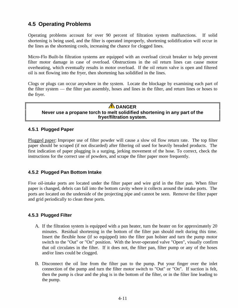
4.5 Operating Problems
Operating problems account for over 90 percent of filtration system malfunctions. If solidshortening is being used, and the filter is operated improperly, shortening solidification will occur inthe lines as the shortening cools, increasing the chance for clogged lines.
Micro-Flo Built-In filtration systems are equipped with an overload circuit breaker to help preventfilter motor damage in case of overload. Obstructions in the oil return lines can cause motoroverheating, which eventually results in motor overload. If the oil return valve is open and filteredoil is not flowing into the fryer, then shortening has solidified in the lines.
Clogs or plugs can occur anywhere in the system. Locate the blockage by examining each part ofthe filter system — the filter pan assembly, hoses and lines in the filter, and return lines or hoses tothe fryer.
DANGERNever use a propane torch to melt solidified shortening in any part of the
fryer/filtration system.
4.5.1 Plugged Paper
Plugged paper: Improper use of filter powder will cause a slow oil flow return rate. The top filterpaper should be scraped (if not discarded) after filtering oil used for heavily breaded products. Thefirst indication of paper plugging is a surging, jerking movement of the hose. To correct, check theinstructions for the correct use of powders, and scrape the filter paper more frequently.
4.5.2 Plugged Pan Bottom Intake
Five oil-intake ports are located under the filter paper and wire grid in the filter pan. When filterpaper is changed, debris can fall into the bottom cavity where it collects around the intake ports. Theports are located on the underside of the projecting pipe and cannot be seen. Remove the filter paperand grid periodically to clean these ports.
4.5.3 Plugged Filter
A. If the filtration system is equipped with a pan heater, turn the heater on for approximately 20minutes. Residual shortening in the bottom of the filter pan should melt during this time.Insert the flexible hose (if so equipped) into the filter pan holster and turn the pump motorswitch to the "Out" or "On" position. With the lever-operated valve "Open", visually confirmthat oil circulates in the filter. If it does not, the filter pan, filter pump or any of the hosesand/or lines could be clogged.
B. Disconnect the oil line from the filter pan to the pump. Put your finger over the inletconnection of the pump and turn the filter motor switch to "Out" or "On". If suction is felt,then the pump is clear and the plug is in the bottom of the filter, or in the filter line leading tothe pump.
4-12
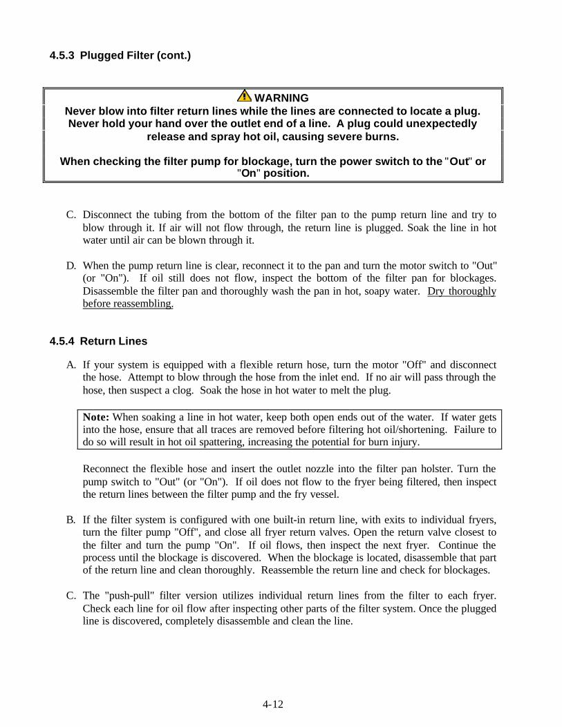
4.5.3 Plugged Filter (cont.)
WARNINGNever blow into filter return lines while the lines are connected to locate a plug.Never hold your hand over the outlet end of a line. A plug could unexpectedly
release and spray hot oil, causing severe burns.
When checking the filter pump for blockage, turn the power switch to the "Out" or"On" position.
C. Disconnect the tubing from the bottom of the filter pan to the pump return line and try toblow through it. If air will not flow through, the return line is plugged. Soak the line in hotwater until air can be blown through it.
D. When the pump return line is clear, reconnect it to the pan and turn the motor switch to "Out"(or "On"). If oil still does not flow, inspect the bottom of the filter pan for blockages.Disassemble the filter pan and thoroughly wash the pan in hot, soapy water. Dry thoroughlybefore reassembling.
4.5.4 Return Lines
A. If your system is equipped with a flexible return hose, turn the motor "Off" and disconnectthe hose. Attempt to blow through the hose from the inlet end. If no air will pass through thehose, then suspect a clog. Soak the hose in hot water to melt the plug.
Note: When soaking a line in hot water, keep both open ends out of the water. If water getsinto the hose, ensure that all traces are removed before filtering hot oil/shortening. Failure todo so will result in hot oil spattering, increasing the potential for burn injury.
Reconnect the flexible hose and insert the outlet nozzle into the filter pan holster. Turn thepump switch to "Out" (or "On"). If oil does not flow to the fryer being filtered, then inspectthe return lines between the filter pump and the fry vessel.
B. If the filter system is configured with one built-in return line, with exits to individual fryers,turn the filter pump "Off", and close all fryer return valves. Open the return valve closest tothe filter and turn the pump "On". If oil flows, then inspect the next fryer. Continue theprocess until the blockage is discovered. When the blockage is located, disassemble that partof the return line and clean thoroughly. Reassemble the return line and check for blockages.
C. The "push-pull" filter version utilizes individual return lines from the filter to each fryer.Check each line for oil flow after inspecting other parts of the filter system. Once the pluggedline is discovered, completely disassemble and clean the line.
4-13
4.5.4 Return Lines (cont.)
To prevent plugged lines when using solid shortening, adhere to the following:
ø If the filter is equipped with a pan heater, use it each time a fryer is filtered.
ø Allow the pump to run for 15-20 seconds after air starts to flow through the lines (or flexiblehose), before shutting off the filter. Clearing residual shortening/oil from the return linesreduces the likelihood of clogged lines.
ø When the filtering cycle is complete, disconnect the flexible line and hang it up to drain.
5-1
MICRO-FLO BUILT-IN SERIES FILTRATION SYSTEMSCHAPTER 5: CLEANING & MAINTENANCE
5.1 Each Filter Use
Every time the Micro-Flo filter is used:
• Wash down the insides of the filter pan with hot oil.• Change the top filter paper sheet after each filter session or at the end of the day. Scrape
sediment from the top sheet after each frypot is filtered within a filter session.• Wipe up any oil which may have splashed or spilled.• Wipe all exterior surfaces of the filter unit.
NOTE: Always scrape sediment and debris from the paper when the system is warm, to prolong thelife of the paper.
CAUTIONDo not run water or boil-out solution through the filtration system. Doing so will
cause irreparable damage to the pump, and the warranty will be voided.
5.2 Daily-Close of Business
At the close of a working day, the last order of business should be to filter the oil in all fryers. Whenthe last fryer is finished, follow these steps:
1. Ensure the flexible hose and pump lines are clear by running the filter pump for anadditional 15–20 seconds after air bubbles start coming from the oil return line. Afterfiltering, hang the flexible hose up to drain.
2. Remove the crumb tray and empty contents into a fireproof container. Remove the hold-down ring assembly, then remove the filter paper and filter support screen.
3. Discard the top filter paper sheet and retain bottom filter paper sheet for re-use.
4. Wash all filter components with hot soapy water and rinse.
5. Dry all filter parts and filter pan thoroughly before reassembling.
6. Check all fittings at the rear of the filter unit; ensure that all fittings are properly tightened.
CAUTIONThe crumb tray (if applicable) in built-in filter systems must be emptied into a
fireproof container at the end of frying operations each day. Some food particlescan spontaneously combust if left soaking in certain shortening material.
5-2
5.3 Weekly
Follow the same procedure as for “Daily”, with these additional steps:
• Wash the filter pan with hot, soapy water and a brush. Dry and reassemble with new filterpaper.
• Clean thoroughly under, around, and behind the fryers and filtering area.
• Do not operate motor/pump until all traces of water have been removed from the pan.Under no circumstances should water or boil-out solution be allowed to enter the pumphousing.
• Check the connections of the inlet lines and tighten if lines become loose or start to leak oil.
6-1
MICRO-FLO BUILT-IN SERIES FILTRATION SYSTEMSCHAPTER 6: TROUBLESHOOTING
6.1 Oil Does Not Re-circulate In Filter and/or Does Not Return To Fryer.
A. System may be plugged with solid shortening in pan sump or in pump. The pump operateswithout circulating oil. See Section 4.5.2 & 4.5.3.
B. Check for loose connections in the suction line. Tighten all loose fittings.
C. Shortening may have solidified in internal return lines; see section 4.5.4.
6.2 Rate Of Oil Return To Fryer Slows.
A. Filter paper is plugged due to too much sediment in fryer. Scrape top filter paper (or replace)after each filtering cycle and filter the oil more frequently.
B. Paper may be plugged by improper use of filter powder. Replace top filter paper and applythe correct amount of filter powder, according to labeled directions.
C. Sediment may be collected around suction pipe in filter bottom. Remove the paper supportgrid and clean out sediment, ensuring that all five inlet ports are free of sediment.
7-1
MICRO-FLO BUILT-IN SERIES FILTRATION SYSTEMSCHAPTER 7: FACTORY SERVICE AND PARTS ORDERING
7.1 Factory Service
FACTORY SERVICE: Call the '800' number on the cover of this manual for the location of yournearest Factory Authorized Service Center (FASC) or contact the factory direct. Always give themodel and serial numbers of your filter.
7.2 Parts Ordering
PARTS ORDERING: Customers may order parts directly from their local FASC. For this addressand phone number, contact your FASC or call the factory. Factory address and phone numbers areon the back cover of this manual.
IMPORTANT
Dean, whose policy is one of constant improvement, reserves the right to amend specifications ofany part or assembly and the materials and finishes comprising the Micro-Flo Filtration system andits accessory equipment without prior notice.
7-2
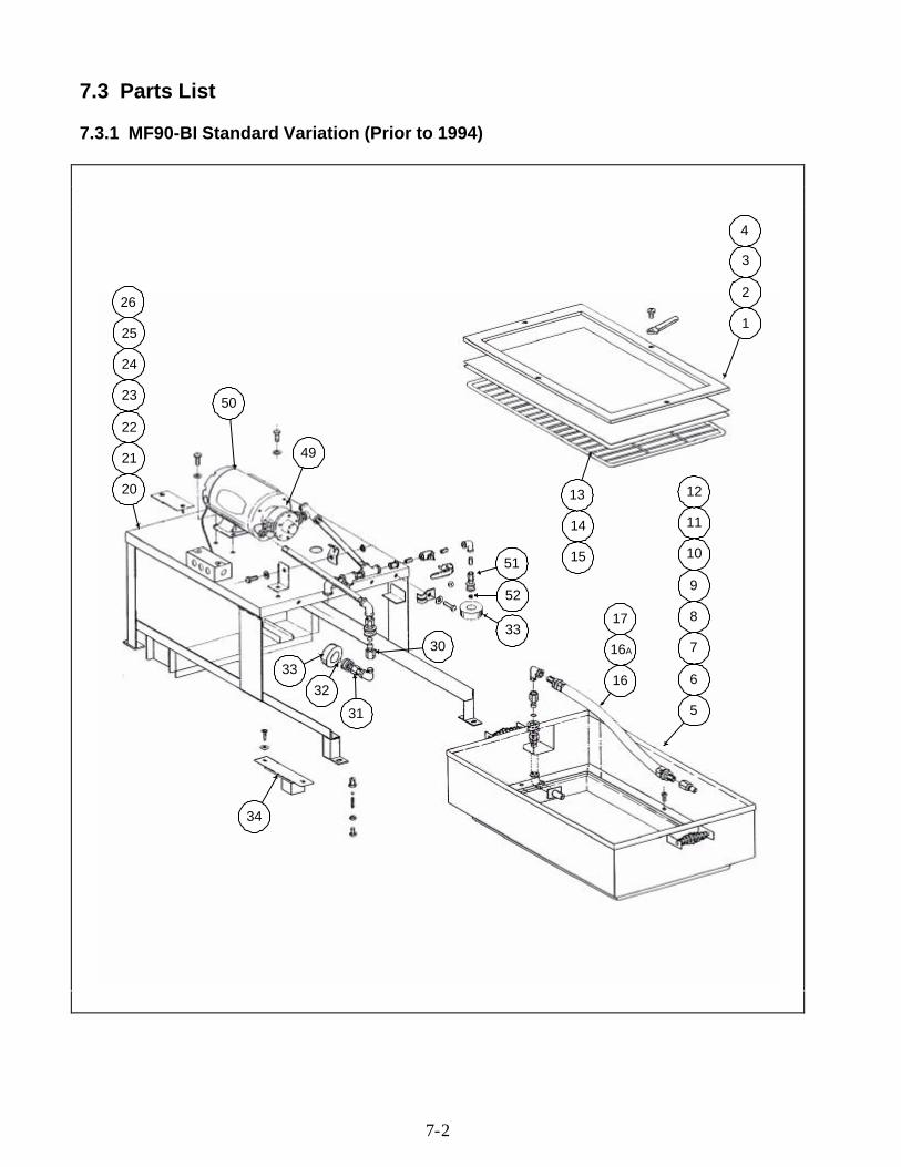
7.3 Parts List
7.3.1 MF90-BI Standard Variation (Prior to 1994)
1
2
3
4
15
14
13
10
11
12
9
8
7
6
5
16
16A
17
51
52
33
24
25
26
23
22
21
20
50
49
3332
31
30
34
7-3
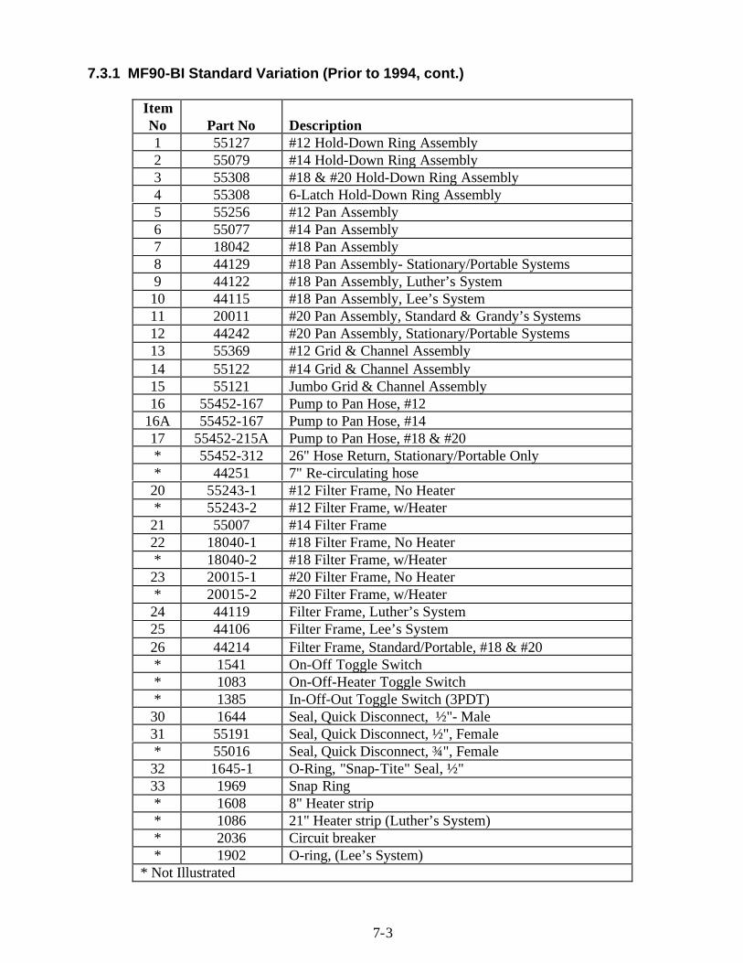
7.3.1 MF90-BI Standard Variation (Prior to 1994, cont.)
ItemNo Part No Description1 55127 #12 Hold-Down Ring Assembly2 55079 #14 Hold-Down Ring Assembly3 55308 #18 & #20 Hold-Down Ring Assembly4 55308 6-Latch Hold-Down Ring Assembly5 55256 #12 Pan Assembly6 55077 #14 Pan Assembly7 18042 #18 Pan Assembly8 44129 #18 Pan Assembly- Stationary/Portable Systems9 44122 #18 Pan Assembly, Luther’s System10 44115 #18 Pan Assembly, Lee’s System11 20011 #20 Pan Assembly, Standard & Grandy’s Systems12 44242 #20 Pan Assembly, Stationary/Portable Systems13 55369 #12 Grid & Channel Assembly14 55122 #14 Grid & Channel Assembly15 55121 Jumbo Grid & Channel Assembly16 55452-167 Pump to Pan Hose, #12
16A 55452-167 Pump to Pan Hose, #1417 55452-215A Pump to Pan Hose, #18 & #20* 55452-312 26" Hose Return, Stationary/Portable Only* 44251 7" Re-circulating hose20 55243-1 #12 Filter Frame, No Heater* 55243-2 #12 Filter Frame, w/Heater21 55007 #14 Filter Frame22 18040-1 #18 Filter Frame, No Heater* 18040-2 #18 Filter Frame, w/Heater23 20015-1 #20 Filter Frame, No Heater* 20015-2 #20 Filter Frame, w/Heater24 44119 Filter Frame, Luther’s System25 44106 Filter Frame, Lee’s System26 44214 Filter Frame, Standard/Portable, #18 & #20* 1541 On-Off Toggle Switch* 1083 On-Off-Heater Toggle Switch* 1385 In-Off-Out Toggle Switch (3PDT)30 1644 Seal, Quick Disconnect, ½"- Male31 55191 Seal, Quick Disconnect, ½", Female* 55016 Seal, Quick Disconnect, ¾", Female32 1645-1 O-Ring, "Snap-Tite" Seal, ½"33 1969 Snap Ring* 1608 8" Heater strip* 1086 21" Heater strip (Luther’s System)* 2036 Circuit breaker* 1902 O-ring, (Lee’s System)
* Not Illustrated
7-4
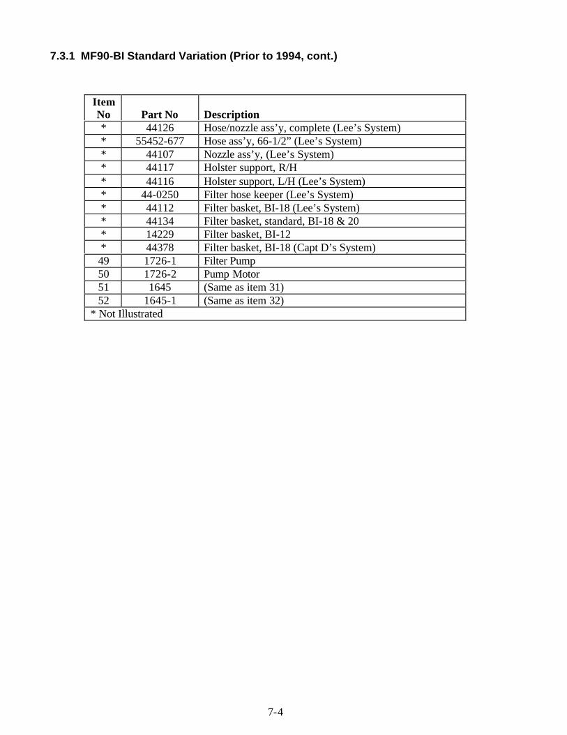
7.3.1 MF90-BI Standard Variation (Prior to 1994, cont.)
ItemNo Part No Description* 44126 Hose/nozzle ass’y, complete (Lee’s System)* 55452-677 Hose ass’y, 66-1/2” (Lee’s System)* 44107 Nozzle ass’y, (Lee’s System)* 44117 Holster support, R/H* 44116 Holster support, L/H (Lee’s System)* 44-0250 Filter hose keeper (Lee’s System)* 44112 Filter basket, BI-18 (Lee’s System)* 44134 Filter basket, standard, BI-18 & 20* 14229 Filter basket, BI-12* 44378 Filter basket, BI-18 (Capt D’s System)49 1726-1 Filter Pump50 1726-2 Pump Motor51 1645 (Same as item 31)52 1645-1 (Same as item 32)
* Not Illustrated
7-5
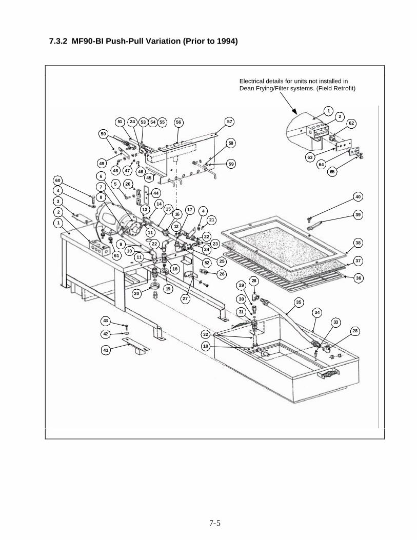
7.3.2 MF90-BI Push-Pull Variation (Prior to 1994)
28
33
34
35
36
37
38
39
40
2829
30
31
32
10
43
42
41
20
1110
9
61
60
4
3
2
1
8
7
6
5 2645
464748
49
50
51 24 53 54 55 56 57
58
59
44
11
1314
15
22
17
24
22
4
21
23
255218
19
27
26
12
62
63
64
65
Electrical details for units not installed inDean Frying/Filter systems. (Field Retrofit)
16
12
7-6
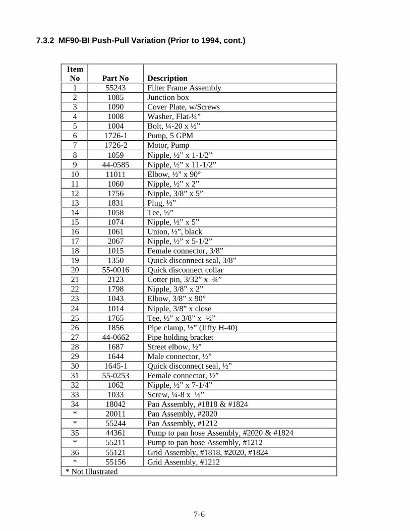
7.3.2 MF90-BI Push-Pull Variation (Prior to 1994, cont.)
ItemNo Part No Description1 55243 Filter Frame Assembly2 1085 Junction box3 1090 Cover Plate, w/Screws4 1008 Washer, Flat-¼”5 1004 Bolt, ¼-20 x ½”6 1726-1 Pump, 5 GPM7 1726-2 Motor, Pump8 1059 Nipple, ½” x 1-1/2”9 44-0585 Nipple, ½” x 11-1/2”10 11011 Elbow, ½” x 90°11 1060 Nipple, ½” x 2”12 1756 Nipple, 3/8” x 5”13 1831 Plug, ½”14 1058 Tee, ½”15 1074 Nipple, ½” x 5”16 1061 Union, ½”, black17 2067 Nipple, ½” x 5-1/2”18 1015 Female connector, 3/8”19 1350 Quick disconnect seal, 3/8”20 55-0016 Quick disconnect collar21 2123 Cotter pin, 3/32” x ¾”22 1798 Nipple, 3/8” x 2”23 1043 Elbow, 3/8” x 90°24 1014 Nipple, 3/8” x close25 1765 Tee, ½” x 3/8” x ½”26 1856 Pipe clamp, ½” (Jiffy H-40)27 44-0662 Pipe holding bracket28 1687 Street elbow, ½”29 1644 Male connector, ½”30 1645-1 Quick disconnect seal, ½”31 55-0253 Female connector, ½”32 1062 Nipple, ½” x 7-1/4”33 1033 Screw, ¼-8 x ½”34 18042 Pan Assembly, #1818 & #1824* 20011 Pan Assembly, #2020* 55244 Pan Assembly, #121235 44361 Pump to pan hose Assembly, #2020 & #1824* 55211 Pump to pan hose Assembly, #121236 55121 Grid Assembly, #1818, #2020, #1824* 55156 Grid Assembly, #1212
* Not Illustrated
7-7
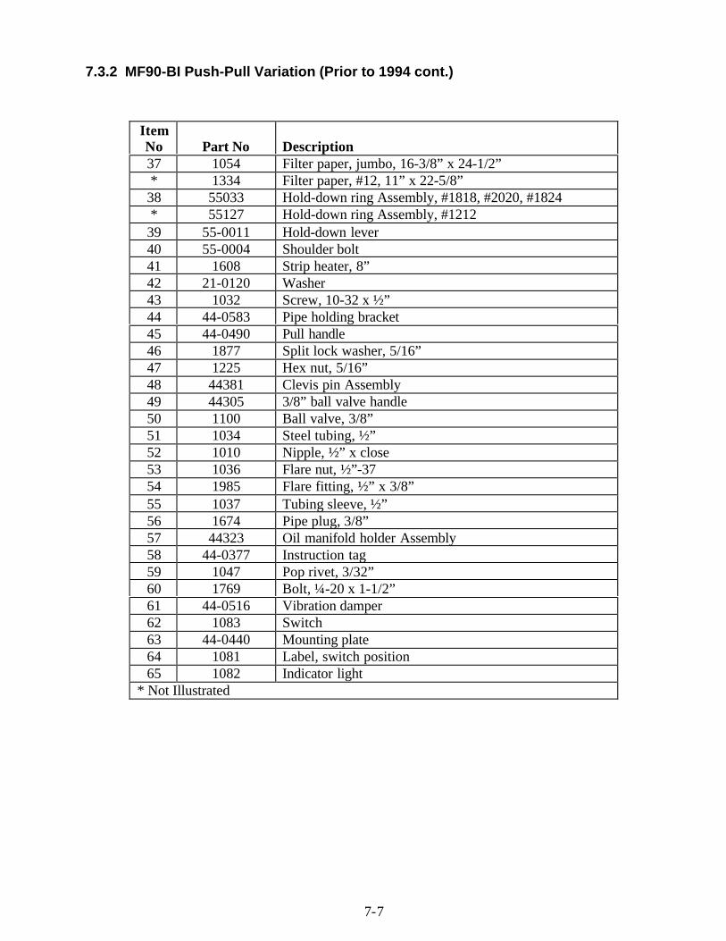
7.3.2 MF90-BI Push-Pull Variation (Prior to 1994 cont.)
ItemNo Part No Description37 1054 Filter paper, jumbo, 16-3/8” x 24-1/2”* 1334 Filter paper, #12, 11” x 22-5/8”38 55033 Hold-down ring Assembly, #1818, #2020, #1824* 55127 Hold-down ring Assembly, #121239 55-0011 Hold-down lever40 55-0004 Shoulder bolt41 1608 Strip heater, 8”42 21-0120 Washer43 1032 Screw, 10-32 x ½”44 44-0583 Pipe holding bracket45 44-0490 Pull handle46 1877 Split lock washer, 5/16”47 1225 Hex nut, 5/16”48 44381 Clevis pin Assembly49 44305 3/8” ball valve handle50 1100 Ball valve, 3/8”51 1034 Steel tubing, ½”52 1010 Nipple, ½” x close53 1036 Flare nut, ½”-3754 1985 Flare fitting, ½” x 3/8”55 1037 Tubing sleeve, ½”56 1674 Pipe plug, 3/8”57 44323 Oil manifold holder Assembly58 44-0377 Instruction tag59 1047 Pop rivet, 3/32”60 1769 Bolt, ¼-20 x 1-1/2”61 44-0516 Vibration damper62 1083 Switch63 44-0440 Mounting plate64 1081 Label, switch position65 1082 Indicator light
* Not Illustrated
7-8
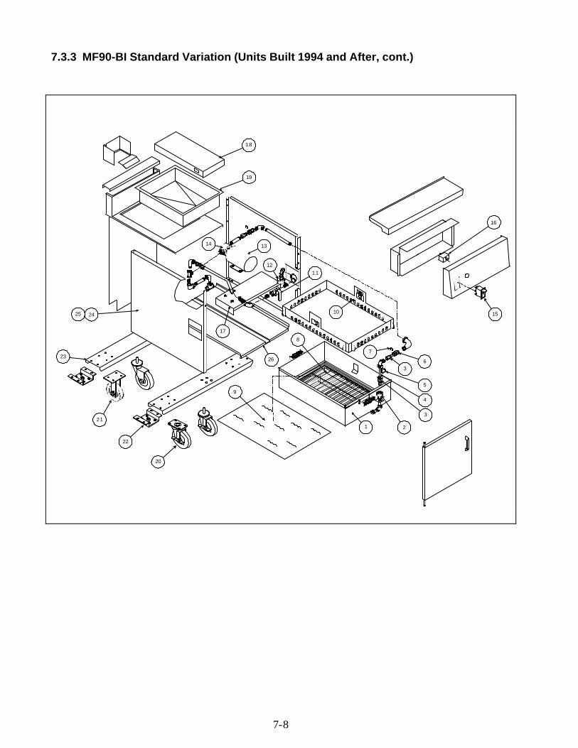
7.3.3 MF90-BI Standard Variation (Units Built 1994 and After, cont.)
10
1 2
3
4
5
36
7
8
9
1112
1314
15
16
17
18
19
20
21
22
23
2425
26
7-9
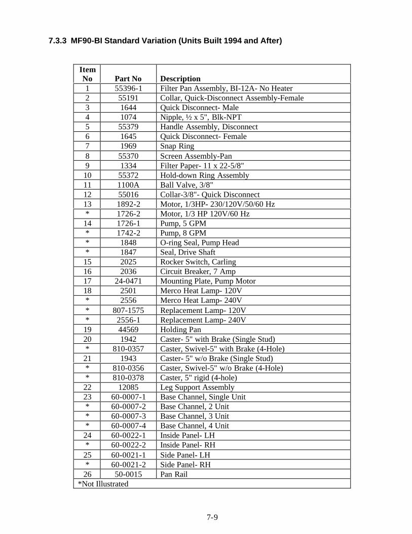
7.3.3 MF90-BI Standard Variation (Units Built 1994 and After)
ItemNo Part No Description1 55396-1 Filter Pan Assembly, BI-12A- No Heater2 55191 Collar, Quick-Disconnect Assembly-Female3 1644 Quick Disconnect- Male4 1074 Nipple, ½ x 5", Blk-NPT5 55379 Handle Assembly, Disconnect6 1645 Quick Disconnect- Female7 1969 Snap Ring8 55370 Screen Assembly-Pan9 1334 Filter Paper- 11 x 22-5/8"10 55372 Hold-down Ring Assembly11 1100A Ball Valve, 3/8"12 55016 Collar-3/8"- Quick Disconnect13 1892-2 Motor, 1/3HP- 230/120V/50/60 Hz* 1726-2 Motor, 1/3 HP 120V/60 Hz14 1726-1 Pump, 5 GPM* 1742-2 Pump, 8 GPM* 1848 O-ring Seal, Pump Head* 1847 Seal, Drive Shaft15 2025 Rocker Switch, Carling16 2036 Circuit Breaker, 7 Amp17 24-0471 Mounting Plate, Pump Motor18 2501 Merco Heat Lamp- 120V* 2556 Merco Heat Lamp- 240V* 807-1575 Replacement Lamp- 120V* 2556-1 Replacement Lamp- 240V19 44569 Holding Pan20 1942 Caster- 5" with Brake (Single Stud)* 810-0357 Caster, Swivel-5" with Brake (4-Hole)21 1943 Caster- 5" w/o Brake (Single Stud)* 810-0356 Caster, Swivel-5" w/o Brake (4-Hole)* 810-0378 Caster, 5" rigid (4-hole)22 12085 Leg Support Assembly23 60-0007-1 Base Channel, Single Unit* 60-0007-2 Base Channel, 2 Unit* 60-0007-3 Base Channel, 3 Unit* 60-0007-4 Base Channel, 4 Unit24 60-0022-1 Inside Panel- LH* 60-0022-2 Inside Panel- RH25 60-0021-1 Side Panel- LH* 60-0021-2 Side Panel- RH26 50-0015 Pan Rail
*Not Illustrated
7-10
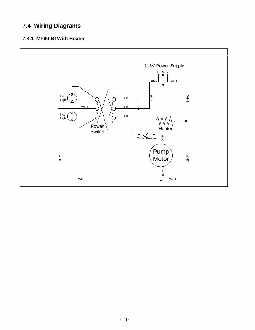
7.4 Wiring Diagrams
7.4.1 MF90-BI With Heater
PumpMotor
3
2
1
6
5
4
Ind.Light
Ind.Light
H NG
Heater
Circuit Breaker
WHT
WHT
WH
T
WH
T
WH
T
WHT
WH
T
WHT
BLK
BLK
BLK
BLK
BLK
BLK
PowerSwitch
115V Power Supply
7-11
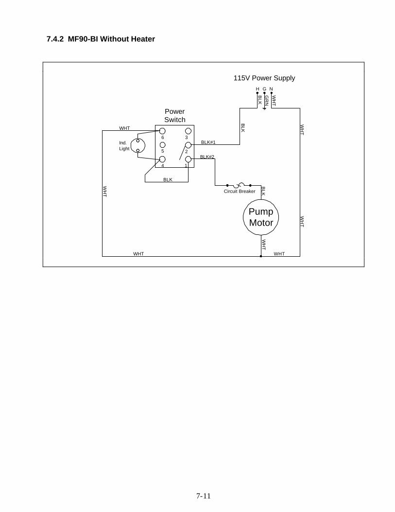
7.4.2 MF90-BI Without Heater
PumpMotor
3
2
1
6
5
4
H NG
Circuit Breaker
WHT
WHT
WH
T
WH
T
WH
T
WHT
WH
T
WH
T
BLK#2
BLK#1
BLK
BLK
BLK
PowerSwitch
Ind.Light
BLK
GR
N
115V Power Supply