Embed Size (px)
Citation preview

8/4/2019 Micro Controllers ECE-310 Final
http://slidepdf.com/reader/full/micro-controllers-ece-310-final 1/10
Homework Title / No. : ___1_______________________Course Code :ECE-310 _________ Course Instructor : _Miss Ritu_____________Course Tutor (if applicable) : ________
Date of Allotment : _____________________ Date of submission :26/02/2010__________
Student’s Roll No.___54____________________ Section No. :RH6802_______________________
Declaration:I declare that this assignment is my individual work. I have not copied from any other student’s work or from any other source except where due acknowledgment is made explicitly in the text, nor has any
part been written for me by another person.
Student’s Signature :
Ramjee prasad__
Evaluator’s comments: _____________________________________________________________________
Marks obtained : ___________ out of ______________________
Content of Homework should start from this page only:
(1)Why microcontrollers are more in use than microprocessors?
Solution:
A microcontroller has a combination of all the following stuff on a single chip:Microcontroller = CPU + Peripherals + MemoryPeripherals = Ports + Clock + Timers + UARTS + ADC +LCD drivers + DAC +
other stuff
Memory = EEPROM + SRAM+ EPROM + FLASH
A microprocessor is just a CPU. If a system designer using a general purpose register such asPentium or the ×86 family must add RAM, ROM, and I/O ports and timers externally tomake them functional. This addition of external peripheral makes the system bulkier andmuch more expensive. A microcontroller is a specialized form of microprocessor that isdesigned to be self-sufficient and cost-effective, where a microprocessor is typically designedto be general purpose. Microcontrollers are frequently found in automobiles, office machines,toys, and appliances.The microcontroller is the integration of a number of useful functions into a single IC
package. These functions are:
8/4/2019 Micro Controllers ECE-310 Final
http://slidepdf.com/reader/full/micro-controllers-ece-310-final 2/10
• The ability to execute a stored set of instructions to carry out user defined tasks.
• The ability to be able to access external memory chips to both read and write datafrom and to the memory.
• discrete input and output bits, allowing control or detection of the logic state of anindividual package pin.
• In-circuit programming and debugging support.
• Also, a microcontroller is part of an embedded system, which is essentially the wholecircuit board. Ex- intercom, telephone, security system, FAX machine, Lightingcontrol, cellular phone, and lots of home appliances, and automation of machine lotsof stuff that make our life easier fast.
A fixed amount of on-chip ROM, RAM, and number of I/O ports in microcontroller makesthem ideal for many applications in which cost and space are critical. In many applicationssuch as TV remote control, there is no need of computing power of ×86 or even 8086microprocessor.
(2)What are the minimum hardware components required for 8051 to work with itsinternal ROM? Also show their connections?
Solution:
The microcontroller uses ROM as memory bank and he keeps the user instruction and storesthe result . For these purpose, the 8051 has two types of memory and these are ProgramMemory and Data Memory. Program Memory (ROM) is used to permanently save the
program being executed, while Data Memory (RAM) is used for temporarily storing data andintermediate results created and used during the operation of the microcontroller. Dependingon the model in use about the 8051 at most a few Kb of ROM and 128 or 256 bytes of RAMis used.
The EEPROM is a special type of memory not contained in all microcontrollers. Its contentsmay be changed during program execution (similar to RAM ), but remains permanently savedeven after the loss of power (similar to ROM). It is often used to store values, created andused during operation (such as calibration values, codes, values to count up to etc.), whichmust be saved after turning the power supply off. A disadvantage of this memory is that the
process of programming is relatively slow. It is measured in miliseconds.
(3)How many internal counters are there in 8051? Explain their working.
8/4/2019 Micro Controllers ECE-310 Final
http://slidepdf.com/reader/full/micro-controllers-ece-310-final 3/10
Solution:
The 8051 microcontroller has 2 timers/counters called T0 and T1. As their names suggest,their main purpose is to measure time and count external events. Besides, they can be usedfor generating clock pulses to be used in serial communication, so called Baud Rate.
Timer T0
The timer T0 consists of two registers – TH0 and TL0 representing a low and a high byte of one 16-digit binary number.
Accordingly, if the content of the timer T0 is equal to 0 (T0=0) then both registers it consistsof will contain 0. If the timer contains for example number 1000 (decimal), then the TH0register (high byte) will contain the number 3, while the TL0 register (low byte) will containdecimal number 232.
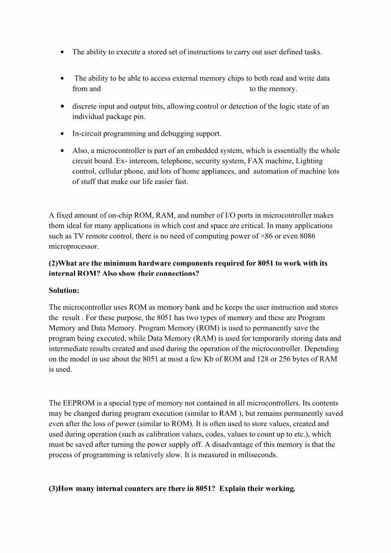
Since the timer T0 is virtually 16-bit register, the largest value it can store is 65 535. In caseof exceeding this value, the timer will be automatically cleared and counting starts from 0.This condition is called an overflow. Two registers TMOD and TCON are closely connectedto this timer and control its operation.
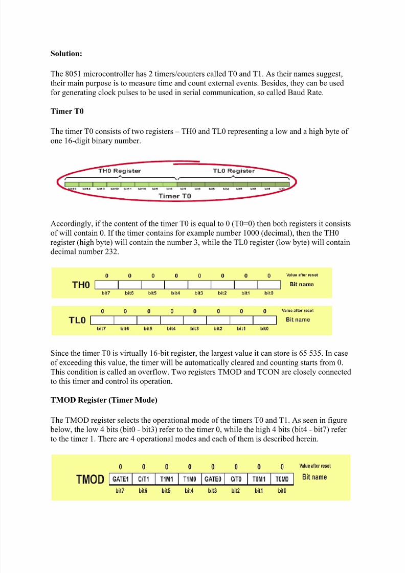
TMOD Register (Timer Mode)
The TMOD register selects the operational mode of the timers T0 and T1. As seen in figure below, the low 4 bits (bit0 - bit3) refer to the timer 0, while the high 4 bits (bit4 - bit7) refer to the timer 1. There are 4 operational modes and each of them is described herein.

8/4/2019 Micro Controllers ECE-310 Final
http://slidepdf.com/reader/full/micro-controllers-ece-310-final 4/10
Bits of this register have the following function:
• GATE1 enables and disables Timer 1 by means of a signal brought to the INT1 pin(P3.3):
o 1 - Timer 1 operates only if the INT1 bit is set.o 0 - Timer 1 operates regardless of the logic state of the INT1 bit.
• C/T1 selects pulses to be counted up by the timer/counter 1:o 1 - Timer counts pulses brought to the T1 pin (P3.5).o 0 - Timer counts pulses from internal oscillator.
• T1M1,T1M0 These two bits select the operational mode of the Timer 1.
T1M1 T1M0 Mode Description
0 0 0 13-bit timer
0 1 1 16-bit timer
1 0 28-bit auto-
reload
1 1 3 Split mode
• GATE0 enables and disables Timer 1 using a signal brought to the INT0 pin (P3.2):o 1 - Timer 0 operates only if the INT0 bit is set.o 0 - Timer 0 operates regardless of the logic state of the INT0 bit.
•
C/T0 selects pulses to be counted up by the timer/counter 0:o 1 - Timer counts pulses brought to the T0 pin (P3.4).o 0 - Timer counts pulses from internal oscillator.
• T0M1,T0M0 these two bits select the operational mode of the Timer 0.
T0M1 T0M0 Mode Description
0 0 0 13-bit timer
0 1 1 16-bit timer
1 0 28-bit auto-
reload
1 1 3 Split mode
Timer 0 in mode 0 (13-bit timer)
This mode configures timer 0 as a 13-bit timer which consists of all 8 bits of TH0 and thelower 5 bits of TL0. As a result, the Timer 0 uses only 13 of 16 bits.
8/4/2019 Micro Controllers ECE-310 Final
http://slidepdf.com/reader/full/micro-controllers-ece-310-final 5/10
Timer 0 in mode 1 (16-bit timer)
Mode 1 configures timer 0 as a 16-bit timer comprising all the bits of both registers TH0 andTL0. That's why this is one of the most commonly used modes. Timer operates in the sameway as in mode 0, with difference that the registers count up to 65 536 as allowable by the 16
bits.
Timer 0 in mode 2 (Auto-Reload Timer)
Mode 2 configures timer 0 as an 8-bit timer. Actually, timer 0 uses only one 8-bit register for counting and never counts from 0, but from an arbitrary value (0-255) stored in another (TH0) register.
Timer 0 in Mode 3 (Split Timer)
Mode 3 configures timer 0 so that registers TL0 and TH0 operate as separate 8-bit timers. Inother words, the 16-bit timer consisting of two registers TH0 and TL0 is split into twoindependent 8-bit timers. This mode is provided for applications requiring an additional 8-bittimer or counter. The TL0 timer turns into timer 0, while the TH0 timer turns into timer 1. Inaddition, all the control bits of 16-bit Timer 1 (consisting of the TH1 and TL1 register), nowcontrol the 8-bit Timer 1. Even though the 16-bit Timer 1 can still be configured to operate inany of modes (mode 1, 2 or 3), it is no longer possible to disable it as there is no control bit todo it. Thus, its operation is restricted when timer 0 is in mode 3.
The only application of this mode is when two timers are used and the 16-bit Timer 1 theoperation of which is out of control is used as a baud rate generator.
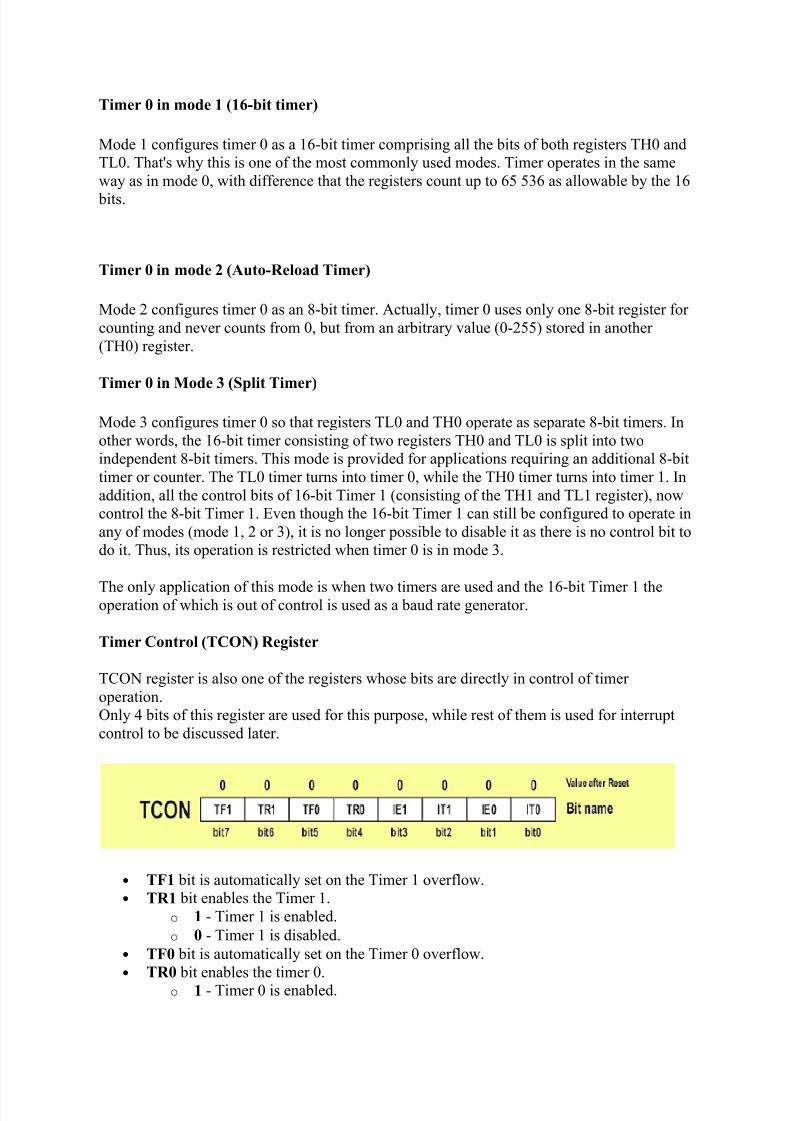
Timer Control (TCON) Register
TCON register is also one of the registers whose bits are directly in control of timer operation.Only 4 bits of this register are used for this purpose, while rest of them is used for interruptcontrol to be discussed later.
• TF1 bit is automatically set on the Timer 1 overflow.• TR1 bit enables the Timer 1.
o 1 - Timer 1 is enabled.o 0 - Timer 1 is disabled.
• TF0 bit is automatically set on the Timer 0 overflow.• TR0 bit enables the timer 0.
o 1 - Timer 0 is enabled.

8/4/2019 Micro Controllers ECE-310 Final
http://slidepdf.com/reader/full/micro-controllers-ece-310-final 6/10
o 0 - Timer 0 is disabled.
PART: B
(1)Draw the internal memory map of 8051 microcontroller.
Solution: Memory Architecture
The 8051 has four types of memory –
(i)internal RAM,
(ii)special function registers,
(iii)program memory,
( i ) external data memory.˅
8/4/2019 Micro Controllers ECE-310 Final
http://slidepdf.com/reader/full/micro-controllers-ece-310-final 7/10
Internal RAM:
Internal RAM is located from address 0 to address 0xFF. RAM from 0x00 to 0x7F can beaccessed directly, and the bytes from 0x20 to 0x3F are also bit-addressable. RAM from 0x80to 0xFF must be accessed indirectly, using the @R0 or @R1 syntax, with the address to
access loaded in R0 or R1.
Special function register:
Special function registers (or, SFR) are located from address 0x80 to 0xFF, and are accesseddirectly using the same instructions as for the lower half of RAM. Some of the SFR's are also
bit-addressable.
program memory:
Program memory (PMEM, though less common in usage than IRAM and XRAM) is locatedstarting at address 0. It may be on- or off-chip, depending on the particular model of chip
being used. Program memory is read-only, though some variants of the 8051 use on-chip
Flash memory:
Flash memory and provide a method of re-programming the memory in-system or in-application. Aside from storing code, program memory can also store tables of constants thatcan be accessed by MOVC A, @DPTR, using the 16-bit special function register DPTR
(2)What are the addressing modes of 8051? How many types of instructions are their?
Solution:
The CPU can access data in various ways. It data could be in a register or be provided as animmediate value. The 8051 provides a total of five distinct addressing modes.
1. Immediate addressing mode
2. Register addressing mode
3. Direct addressing mode
4. Register addressing mode
5. Indexed addressing mode
Immediate addressing mode:
In this addressing mode, the source operand is constant. In immediate addressing mode, theoperand comes immediately. The immediate data must be preceded by the pound sign “#”sign.
8/4/2019 Micro Controllers ECE-310 Final
http://slidepdf.com/reader/full/micro-controllers-ece-310-final 8/10
The followings instruction are used in these addressing mode:
MOV A, #25H ; load 25H into accumulator A
MOV R4, #62H ; load the decimal value 62 into R4
MOV B, #40H ; load 40H into B
MOV DPTR, #4521H; DPTR= 4521H
Since the DPTR register is of 16-bit, it can also be accessed as two 8-bit registers, DPH andDPL, where DPH is high byte and DPL is the low byte.
MOV DPTR, #2553H is same as the,
MOV DPL, #53H
MOV DPH, # 25H
We can use the EQU directive to access immediate data as shown below:
COUNT EQU 30
... ..
MOV R4, #COUNT ; R4= 1E(30=1EH)
MOV DPTR, #MYDATA ; DPTR=200H
To send the data to port to 8051 ports.
Ex: MOV P1, #55H
Register addressing mode:
register addressing mode involves the use of register to hold the data to be manipulated. Ex:-
MOV A, RO ; Copy the contents of RO in A
MOV R2, A ; Copy the contents of A in RO
ADD A, R5
ADD R5, A
in this mode the source and destination register must be the same size otherwise it will showserror
In this we can move data between them and Rn (for n= 0 to 7) but movement of between Rnregister is not allowed.
Direct addressing mode:
8/4/2019 Micro Controllers ECE-310 Final
http://slidepdf.com/reader/full/micro-controllers-ece-310-final 9/10
In the Direct addressing mode, the data is in RAM memory location whose address isknown , and this address is given as a part of the instruction. Compare with the immediateaddressing mode , in which the operand itself provide with the instruction. The “#” signdistinguishes between the two modes. Ex:-
MOV RO, 40H
MOV 56H, A
MOV R4, 7F
The RAM locations 0 to 7 are allocated to bank 0 registers R0-R7. these register can beaccessed in two ways,
MOV A, 4
Or, MOV A, R4
See the following code;
MOV R2, #5
MOV A, 2
MOV B, 2
MOV 7, 2 ; Copy R2 to R7
;since “MOV R7, R2” is invalid
Although it is easier to use the names R0-R7 than their memory addresses, RAM locations30H to 7FH can not be accessed in any way other than by their addresses, since they have nonames.
Register indirect addressing mode:
In the register addressing mode , aregister is used as a pointer to the data. if the data is insidethe CPU, only register R0 and R1 are used for this purpose. When R0-R1 are used to hold the
address of RAM locations, they must be preceded by the “@” sign, as shown below,
MOV A,@R0 ;move contents of RAM locations whose
; address is held by R0 into A
Indexedr addressing mode:
Indexed addressing mode is used in accessing data elements of look-up table located in the program
8/4/2019 Micro Controllers ECE-310 Final
http://slidepdf.com/reader/full/micro-controllers-ece-310-final 10/10
ROM space of the 8051.the instruction used for this purpose is “MOV A, @+DPTR”. The16-bit register DPTR and register A are used to form the address of the data element storedon-chip ROM.
(3)If external memory (ROM) have to be used with 8051 then how much memory can beconnected and why?
Answer: - In case memory (RAM or ROM) built in the microcontroller is notsufficient, it is possible to add two external memory chips with capacity of 64Kbeach. P2 and P3 I/O ports are used for their addressing and data transmission.
• In the 8051 microcontroller, there are 16 address lines from port 0 and port 2there for we can excess 216 = 64 K of external memory i.e. ROM.
• External memory is used in cases when the internal ROM and RAM memory
available on chip is not sufficient. Two separate external memory spaces aremade available by the 16-bit PC and the DPTR and by different control pinsenabling external RIM chips.
• Two external ROM of up to 64 K can be added to any chip in the 8051family.