Embed Size (px)
Citation preview
Micro-Comm RTU32 PLC
User’s Reference Manual(for S4500, M1500, M550, M555, M1550, M1650, M655, M1600)
Revised: June 21, 2016
Copyright © 2016 Micro-Comm, Inc.
Table of Contents
S4500 PLC .....................................................................................................................................................3S4500 Specifications and Sales Information ............................................................................................4
M1500 PLC ....................................................................................................................................................6M1500 Specifications and Sales Information ..........................................................................................7
M550 PLC ......................................................................................................................................................9M550 Specifications and Sales Information ..........................................................................................10
M555 PLC .................................................................................................................................................... 11M555 Specifications and Sales Information ..........................................................................................12M555 Installation Requirements ............................................................................................................14M555 Lithium Battery Replacement .....................................................................................................15
M1550 PLC ..................................................................................................................................................16M1550 Specifications and Sales Information ........................................................................................17M1550 Installation Requirements ..........................................................................................................19M1550 Lithium Battery Replacement ...................................................................................................20
M1650, M655 and M1600 PLC ...................................................................................................................21M1650 Specifications and Sales Information ........................................................................................22M655 Specifications and Sales Information ..........................................................................................24M1600 Specifications and Sales Information ........................................................................................26
Expansion I/O Module Setup .......................................................................................................................28Communication Port Pinouts .......................................................................................................................29Display Module Operation ...........................................................................................................................30RTU32 Protocol I/O Mapping .....................................................................................................................31Allen-Bradley DF1 and Modbus Protocol Support .....................................................................................33Allen-Bradley Ethernet/IP and Modbus/TCP Protocol Support ..................................................................34RTU Configuration 32 ..................................................................................................................................35
Program Installation ...............................................................................................................................35RTU Information Screen ........................................................................................................................36Configuration Parameters .......................................................................................................................37Analog Labels and Scaling Factors ........................................................................................................41Output Timer Labels ..............................................................................................................................42Stop/Start Setpoint Labels ......................................................................................................................43X Variable Labels ...................................................................................................................................44Discrete I/O Labels ................................................................................................................................45User Memory Screens ............................................................................................................................46User Memory Table ...............................................................................................................................47RTU Script Language Editor .................................................................................................................48Commented Script / Revision Editor .....................................................................................................49Data Table Viewer ..................................................................................................................................50Display Module Emulator ......................................................................................................................51Debug Terminal ......................................................................................................................................52
- 3 -
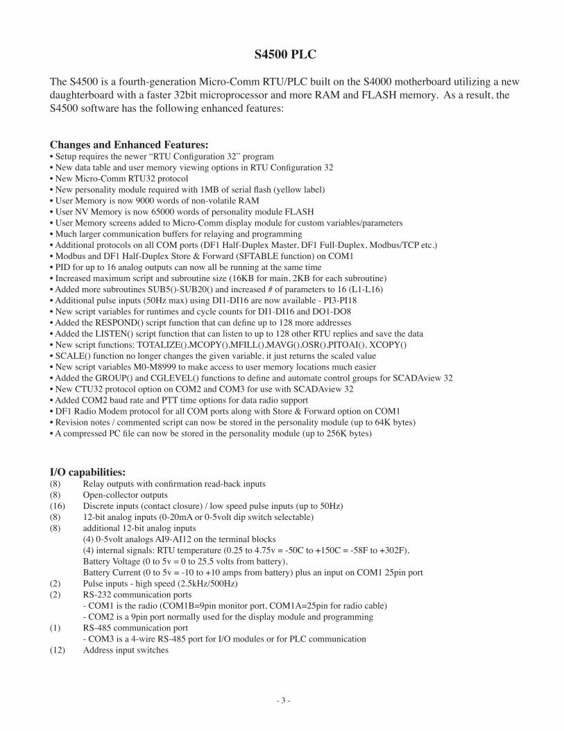
S4500 PLC
The S4500 is a fourth-generation Micro-Comm RTU/PLC built on the S4000 motherboard utilizing a new daughterboard with a faster 32bit microprocessor and more RAM and FLASH memory. As a result, the S4500 software has the following enhanced features:
I/O capabilities:(8) Relay outputs with confirmation read-back inputs(8) Open-collector outputs(16) Discrete inputs (contact closure) / low speed pulse inputs (up to 50Hz)(8) 12-bit analog inputs (0-20mA or 0-5volt dip switch selectable)(8) additional 12-bit analog inputs (4) 0-5volt analogs AI9-AI12 on the terminal blocks (4) internal signals: RTU temperature (0.25 to 4.75v = -50C to +150C = -58F to +302F), Battery Voltage (0 to 5v = 0 to 25.5 volts from battery), Battery Current (0 to 5v = -10 to +10 amps from battery) plus an input on COM1 25pin port(2) Pulse inputs - high speed (2.5kHz/500Hz)(2) RS-232 communication ports - COM1 is the radio (COM1B=9pin monitor port, COM1A=25pin for radio cable) - COM2 is a 9pin port normally used for the display module and programming(1) RS-485 communication port
- COM3 is a 4-wire RS-485 port for I/O modules or for PLC communication(12) Address input switches
Changes and Enhanced Features:• Setup requires the newer “RTU Configuration 32” program• New data table and user memory viewing options in RTU Configuration 32• New Micro-Comm RTU32 protocol • New personality module required with 1MB of serial flash (yellow label)• User Memory is now 9000 words of non-volatile RAM• User NV Memory is now 65000 words of personality module FLASH• User Memory screens added to Micro-Comm display module for custom variables/parameters• Much larger communication buffers for relaying and programming• Additional protocols on all COM ports (DF1 Half-Duplex Master, DF1 Full-Duplex, Modbus/TCP etc.)• Modbus and DF1 Half-Duplex Store & Forward (SFTABLE function) on COM1• PID for up to 16 analog outputs can now all be running at the same time• Increased maximum script and subroutine size (16KB for main, 2KB for each subroutine)• Added more subroutines SUB5()-SUB20() and increased # of parameters to 16 (L1-L16)• Additional pulse inputs (50Hz max) using DI1-DI16 are now available - PI3-PI18• New script variables for runtimes and cycle counts for DI1-DI16 and DO1-DO8• Added the RESPOND() script function that can define up to 128 more addresses• Added the LISTEN() script function that can listen to up to 128 other RTU replies and save the data• New script functions: TOTALIZE(),MCOPY(),MFILL(),MAVG(),OSR(),PITOAI(), XCOPY()• SCALE() function no longer changes the given variable, it just returns the scaled value• New script variables M0-M8999 to make access to user memory locations much easier• Added the GROUP() and CGLEVEL() functions to define and automate control groups for SCADAview 32• New CTU32 protocol option on COM2 and COM3 for use with SCADAview 32• Added COM2 baud rate and PTT time options for data radio support• DF1 Radio Modem protocol for all COM ports along with Store & Forward option on COM1• Revision notes / commented script can now be stored in the personality module (up to 64K bytes)• A compressed PC file can now be stored in the personality module (up to 256K bytes)
- 4 -
S4500 Specifications and Sales Information
Programmable logic controller (Plc)
fully Programmable with Plug-in memory module
micro-comm rtu, modbus rtu & allen-bradley df1 Protocols
oPtional front Panel disPlay & exPandable i/o
radio, Phone line, & fiber oPtic communications
simultaneous rtu-rtu & ctu-rtu communications
Plug-in terminal blocks
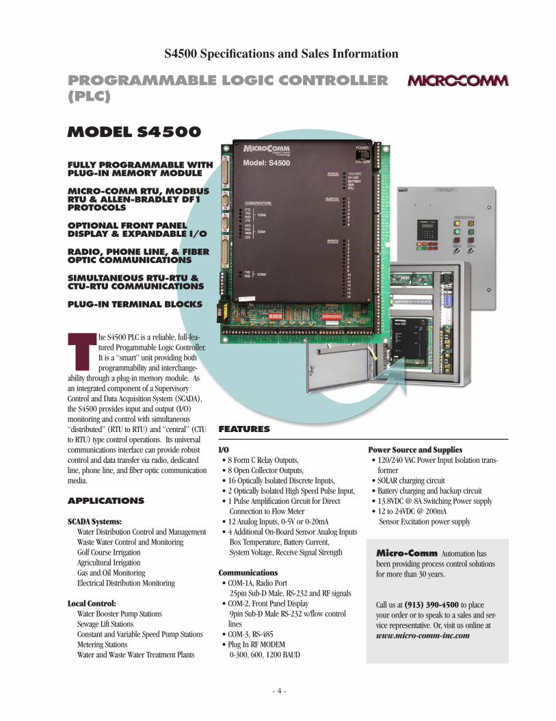
t he S4500 PLC is a reliable, full-fea-tured Progammable Logic Controller. It is a “smart” unit providing both programmability and interchange-
ability through a plug-in memory module. As an integrated component of a Supervisory Control and Data Acquisition System (SCADA), the S4500 provides input and output (I/O) monitoring and control with simultaneous “distributed” (RTU to RTU) and “central” (CTU to RTU) type control operations. Its universal communications interface can provide robust control and data transfer via radio, dedicated line, phone line, and fiber optic communication media.
aPPlications
SCADA Systems: Water Distribution Control and Management Waste Water Control and Monitoring Golf Course Irrigation Agricultural Irrigation Gas and Oil Monitoring Electrical Distribution Monitoring
Local Control: Water Booster Pump Stations Sewage Lift Stations Constant and Variable Speed Pump Stations Metering Stations Water and Waste Water Treatment Plants
model s4500
features
I/O• 8 Form C Relay Outputs,• 8 Open Collector Outputs,• 16 Optically Isolated Discrete Inputs,• 2 Optically Isolated High Speed Pulse Input, • 1 Pulse Amplification Circuit for Direct Connection to Flow Meter• 12 Analog Inputs, 0-5V or 0-20mA • 4 Additional On-Board Sensor Analog Inputs Box Temperature, Battery Current, System Voltage, Receive Signal Strength
Communications• COM-1A, Radio Port 25pin Sub-D Male, RS-232 and RF signals• COM-2, Front Panel Display 9pin Sub-D Male RS-232 w/flow control
lines • COM-3, RS-485• Plug In RF MODEM 0-300, 600, 1200 BAUD
Power Source and Supplies• 120/240 VAC Power Input Isolation trans-
former • SOLAR charging circuit• Battery charging and backup circuit• 13.8VDC @ 8A Switching Power supply• 12 to 24VDC @ 200mA Sensor Excitation power supply
micro-comm Automation has been providing process control solutions for more than 30 years.
Call us at (913) 390-4500 to place your order or to speak to a sales and ser-vice representative. Or, visit us online at www.micro-comm-inc.com
- 5 -
i/o
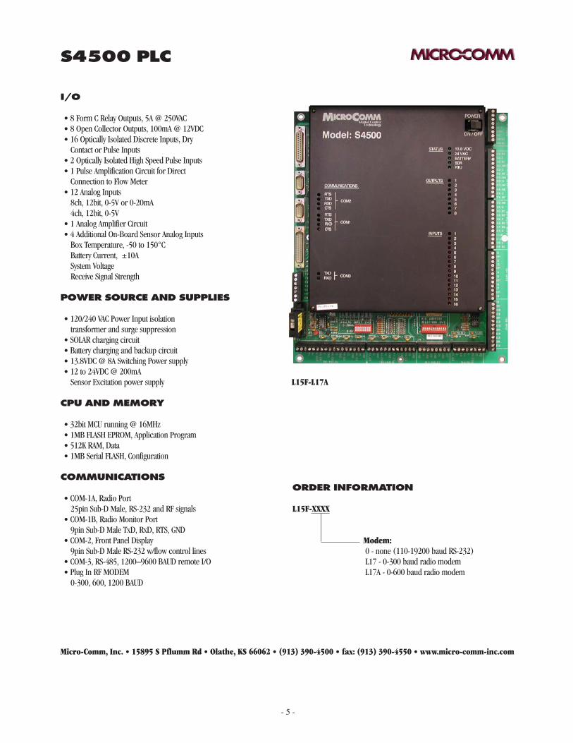
• 8 Form C Relay Outputs, 5A @ 250VAC • 8 Open Collector Outputs, 100mA @ 12VDC• 16 Optically Isolated Discrete Inputs, Dry Contact or Pulse Inputs• 2 Optically Isolated High Speed Pulse Inputs • 1 Pulse Amplification Circuit for Direct Connection to Flow Meter• 12 Analog Inputs 8ch, 12bit, 0-5V or 0-20mA 4ch, 12bit, 0-5V• 1 Analog Amplifier Circuit• 4 Additional On-Board Sensor Analog Inputs Box Temperature, -50 to 150°C Battery Current, ±10A System Voltage Receive Signal Strength
Power source and suPPlies
• 120/240 VAC Power Input isolation transformer and surge suppression• SOLAR charging circuit• Battery charging and backup circuit• 13.8VDC @ 8A Switching Power supply• 12 to 24VDC @ 200mA Sensor Excitation power supply
cPu and memory
• 32bit MCU running @ 16MHz• 1MB FLASH EPROM, Application Program• 512K RAM, Data• 1MB Serial FLASH, Configuration
communications
• COM-1A, Radio Port 25pin Sub-D Male, RS-232 and RF signals• COM-1B, Radio Monitor Port 9pin Sub-D Male TxD, RxD, RTS, GND• COM-2, Front Panel Display 9pin Sub-D Male RS-232 w/flow control lines • COM-3, RS-485, 1200–9600 BAUD remote I/O• Plug In RF MODEM 0-300, 600, 1200 BAUD
order information
L15F-xxxx
Modem: 0 - none (110-19200 baud RS-232) L17 - 0-300 baud radio modem L17A - 0-600 baud radio modem
Micro-Comm, Inc. • 15895 S Pflumm Rd • Olathe, KS 66062 • (913) 390-4500 • fax: (913) 390-4550 • www.micro-comm-inc.com
s4500 Plc
L15F-L17A
- 6 -
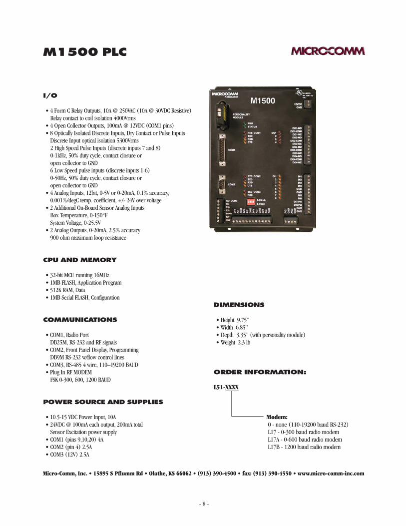
M1500 PLC
The M1500 is a fourth-generation Micro-Comm controller built with the processor daughterboard from the S4500 (32bit microprocessor). The M1500 is physically much smaller than the S4500, having the reduced I/O count listed below:
I/O capabilities:(4) Relay outputs(4) Open-collector outputs (COM1 pins used for radio switching)(8) Discrete inputs (contact closure), (2) high speed pulse, (6) low speed pulse(4) Analog Inputs (12bit, 0-20mA or 0-5volt dip switch selectable)(2) additional 12bit analog inputs Temperature (0.25 to 4.75v = -50C to +150C = -58F to +302F), System Voltage (0 to 5v = 0 to 25.5 volts)(2) Analog Outputs (0-20mA)(2) RS-232 communication ports - COM1 25pin port for radio cable - COM2 9pin port normally used for the display module and programming(1) RS-485 communication port
- COM3 is a 4-wire RS-485 port for I/O modules or for PLC communication
- 7 -
M1500 Specifications and Sales Information
fully programmable with plug-in memory module
miCro-Comm, modbus rtu and allen-bradley df1 protoCols
optional front panel display & expandable i/o
radio, phone line, & fiber optiC CommuniCations
simultaneous rtu-rtu & Ctu-rtu CommuniCations
plug-in terminal bloCks
model m1500
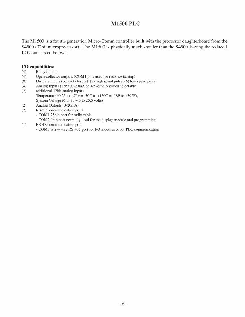
t he M1500 PLC is a reliable, full-featured Programmable Logic Controller. It is a “smart” unit providing both programmability and
interchangeability through a plug-in memory module. As an integrated component of a Supervisory Control and Data Acquisition System (SCADA), the M1500 provides input and output (I/O) monitoring and control with simultaneous “distributed” (RTU to RTU) and “central” (CTU to RTU) type control operations. Its universal communications interface can provide robust control and data transfer via radio, dedicated line, phone line, and fiber optic communication media.
appliCations
SCADA Systems: Water Distribution Control and Management Waste Water Control and Monitoring Golf Course Irrigation Agricultural Irrigation Gas and Oil Monitoring Electrical Distribution Monitoring
Local Control: Water Booster Pump Stations Sewage Lift Stations Constant and Variable Speed Pump Stations Metering Stations Water and Waste Water Treatment Plants
features
I/O• 4 Form C Relay Outputs• 4 Open Collector Outputs• 8 Optically Isolated Discrete Inputs (2 are also High Speed Pulse Inputs)• 4 Analog Inputs, 0-5V or 0-20mA • 2 Additional On-Board Sensor Analog Inputs Box Temperature, System Voltage• 2 Analog Outputs, 0-20mA
Communications• COM1, Radio Port 25pin Sub-D Male, RS-232 and RF signals• COM2, Front Panel Display, Programming 9pin Sub-D Male RS-232 w/flow control
lines for optional 2nd data radio• COM3, RS-485, Expansion I/O• Plug In RF MODEM 0-300, 600, 1200 BAUD
Power Source and Supplies• 12 VDC Power Input• 24VDC @ 200mA Sensor Excitation power supply
micro-Comm Automation has been providing process control solutions for more than 30 years.
Call us at (913) 390-4500 to place your order or to speak to a sales and ser-vice representative. Or, visit us online at www.micro-comm-inc.com
programmable logiC Controller (plC)
- 8 -
order information:
L51-xxxx
Modem: 0 - none (110-19200 baud RS-232) L17 - 0-300 baud radio modem L17A - 0-600 baud radio modem L17B - 1200 baud radio modem
Micro-Comm, Inc. • 15895 S Pflumm Rd • Olathe, KS 66062 • (913) 390-4500 • fax: (913) 390-4550 • www.micro-comm-inc.com
m1500 plC
i/o
• 4 Form C Relay Outputs, 10A @ 250VAC (10A @ 30VDC Resistive) Relay contact to coil isolation 4000Vrms• 4 Open Collector Outputs, 100mA @ 12VDC (COM1 pins)• 8 Optically Isolated Discrete Inputs, Dry Contact or Pulse Inputs Discrete Input optical isolation 5300Vrms 2 High Speed Pulse Inputs (discrete inputs 7 and 8) 0-1kHz, 50% duty cycle, contact closure or open collector to GND 6 Low Speed pulse inputs (discrete inputs 1-6) 0-50Hz, 50% duty cycle, contact closure or open collector to GND• 4 Analog Inputs, 12bit, 0-5V or 0-20mA, 0.1% accuracy, 0.001%/degC temp. coefficient, +/- 24V over voltage• 2 Additional On-Board Sensor Analog Inputs Box Temperature, 0-150°F System Voltage, 0-25.5V• 2 Analog Outputs, 0-20mA, 2.5% accuracy 900 ohm maximum loop resistance
power sourCe and supplies
• 10.5-15 VDC Power Input, 10A • 24VDC @ 100mA each output, 200mA total Sensor Excitation power supply• COM1 (pins 9,10,20) 4A• COM2 (pin 4) 2.5A• COM3 (12V) 2.5A
Cpu and memory
• 32-bit MCU running 16MHz• 1MB FLASH, Application Program• 512K RAM, Data• 1MB Serial FLASH, Configuration
CommuniCations
• COM1, Radio Port DB25M, RS-232 and RF signals• COM2, Front Panel Display, Programming DB9M RS-232 w/flow control lines • COM3, RS-485 4 wire, 110–19200 BAUD• Plug In RF MODEM FSK 0-300, 600, 1200 BAUD
dimensions
• Height 9.75”• Width 6.85”• Depth 3.35” (with personality module)• Weight 2.3 lb
- 9 -
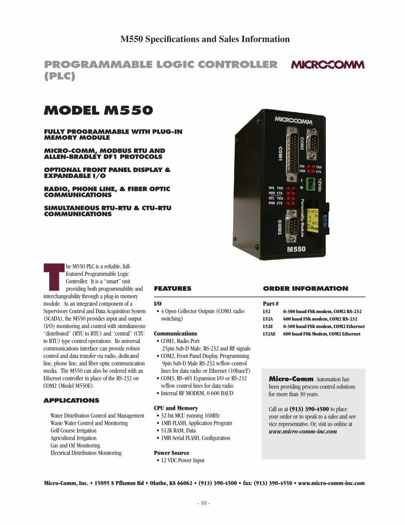
M550 PLC
The M550 is a fourth-generation Micro-Comm controller built with the processor daughterboard from the S4500 (32bit microprocessor). The M550E is a version of the M550 with an Ethernet port in place of the COM2 serial port.
The M550 is physically much smaller than the S4500, having the reduced I/O count listed below:
I/O capabilities:(4) Open-collector outputs (COM1 pins used for radio switching)(2) On-board 12bit analog inputs Temperature (0.25 to 4.75v = -50C to +150C = -58F to +302F), System Voltage (0 to 5v = 0 to 25.5 volts)(3) Communication ports - COM1 25pin port for radio cable - COM2 9pin port used for the display module and programming (Note: The M550E has an Ethernet 10baseT port for COM2)
- COM3 can be configured as an RS-485 port for I/O modules or as an RS-232 port with PTT supprt
- 10 -
M550 Specifications and Sales Information
fully programmable with plug-in memory module
miCro-Comm, modbus rtu and allen-bradley df1 protoCols
optional front panel display & expandable i/o
radio, phone line, & fiber optiC CommuniCations
simultaneous rtu-rtu & Ctu-rtu CommuniCations
model m550
t he M550 PLC is a reliable, full-featured Programmable Logic Controller. It is a “smart” unit providing both programmability and
interchangeability through a plug-in memory module. As an integrated component of a Supervisory Control and Data Acquisition System (SCADA), the M550 provides input and output (I/O) monitoring and control with simultaneous “distributed” (RTU to RTU) and “central” (CTU to RTU) type control operations. Its universal communications interface can provide robust control and data transfer via radio, dedicated line, phone line, and fiber optic communication media. The M550 can also be ordered with an Ethernet controller in place of the RS-232 on COM2 (Model M550E).
appliCations
Water Distribution Control and Management Waste Water Control and Monitoring Golf Course Irrigation Agricultural Irrigation Gas and Oil Monitoring Electrical Distribution Monitoring
features
I/O• 4 Open Collector Outputs (COM1 radio
switching)
Communications• COM1, Radio Port 25pin Sub-D Male, RS-232 and RF signals• COM2, Front Panel Display, Programming 9pin Sub-D Male RS-232 w/flow control
lines for data radio or Ethernet (10baseT)• COM3, RS-485 Expansion I/O or RS-232
w/flow control lines for data radio• Internal RF MODEM, 0-600 BAUD
CPU and Memory• 32-bit MCU running 16MHz• 1MB FLASH, Application Program• 512K RAM, Data• 1MB Serial FLASH, Configuration
Power Source• 12 VDC Power Input
order information
Part # L52 0-300 baud FSK modem, COM2 RS-232 L52A 600 baud FSK modem, COM2 RS-232 L52E 0-300 baud FSK modem, COM2 Ethernet L52AE 600 baud FSK Modem, COM2 Ethernet
micro-Comm Automation has been providing process control solutions for more than 30 years.
Call us at (913) 390-4500 to place your order or to speak to a sales and ser-vice representative. Or, visit us online at www.micro-comm-inc.com
Micro-Comm, Inc. • 15895 S Pflumm Rd • Olathe, KS 66062 • (913) 390-4500 • fax: (913) 390-4550 • www.micro-comm-inc.com
programmable logiC Controller (plC)
- 11 -
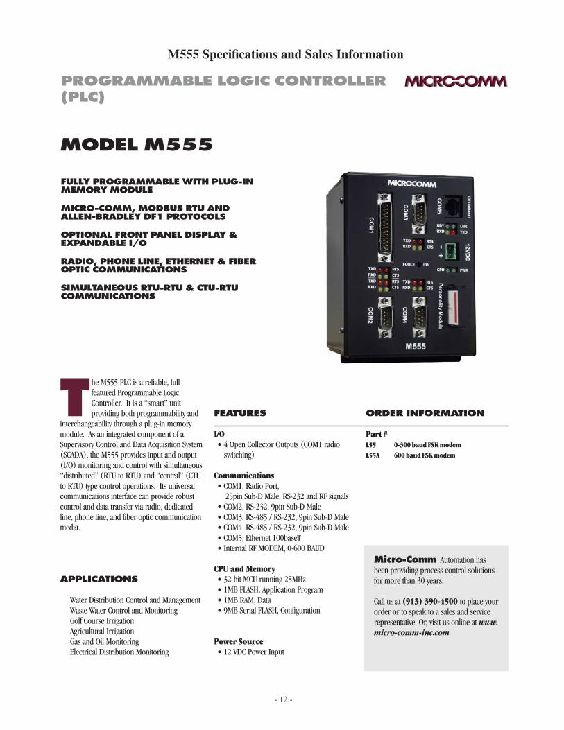
M555 PLC
The M555 is a fifth-generation Micro-Comm controller similar to the M550E PLC, but with a faster processor, more memory, faster ethernet port and 2 additional communication ports.
I/O capabilities:(4) Open-collector outputs (COM1 pins used for radio switching)(2) On-board 12bit analog inputs Temperature (0.25 to 4.75v = -50C to +150C = -58F to +302F), System Voltage (0 to 5v = 0 to 25.5 volts)(3) Communication ports - COM1 25pin port for radio cable - COM2 9pin port used for the display module and programming
- COM3 9pin can be configured as an RS-485 port for I/O modules or as an RS-232 port with PTT supprt- COM4 9pin can be configured as RS-485/RS-232- COM5 is an Ethernet 100baseT (RJ-45) port
- 12 -
M555 Specifications and Sales Information
fully programmable with plug-in memory module
miCro-Comm, modbus rtu and allen-bradley df1 protoCols
optional front panel display & expandable i/o
radio, phone line, ethernet & fiber optiC CommuniCations
simultaneous rtu-rtu & Ctu-rtu CommuniCations
model m555
t he M555 PLC is a reliable, full-featured Programmable Logic Controller. It is a “smart” unit providing both programmability and
interchangeability through a plug-in memory module. As an integrated component of a Supervisory Control and Data Acquisition System (SCADA), the M555 provides input and output (I/O) monitoring and control with simultaneous “distributed” (RTU to RTU) and “central” (CTU to RTU) type control operations. Its universal communications interface can provide robust control and data transfer via radio, dedicated line, phone line, and fiber optic communication media.
appliCations
Water Distribution Control and Management Waste Water Control and Monitoring Golf Course Irrigation Agricultural Irrigation Gas and Oil Monitoring Electrical Distribution Monitoring
features
I/O• 4 Open Collector Outputs (COM1 radio
switching)
Communications• COM1, Radio Port, 25pin Sub-D Male, RS-232 and RF signals• COM2, RS-232, 9pin Sub-D Male• COM3, RS-485 / RS-232, 9pin Sub-D Male• COM4, RS-485 / RS-232, 9pin Sub-D Male• COM5, Ethernet 100baseT• Internal RF MODEM, 0-600 BAUD
CPU and Memory• 32-bit MCU running 25MHz• 1MB FLASH, Application Program• 1MB RAM, Data• 9MB Serial FLASH, Configuration
Power Source• 12 VDC Power Input
order information
Part # L55 0-300 baud FSK modem L55A 600 baud FSK modem
micro-Comm Automation has been providing process control solutions for more than 30 years.
Call us at (913) 390-4500 to place your order or to speak to a sales and service representative. Or, visit us online at www.micro-comm-inc.com
programmable logiC Controller (plC)
- 13 -
order information:
L55x
Modem: L55 - 0-300 baud FSK modem L55A - 0-600 baud FSK modem L55B - 1200 baud FSK modem
Micro-Comm, Inc. • 15895 S Pflumm Rd • Olathe, KS 66062 • (913) 390-4500 • fax: (913) 390-4550 • www.micro-comm-inc.com
m555 plC
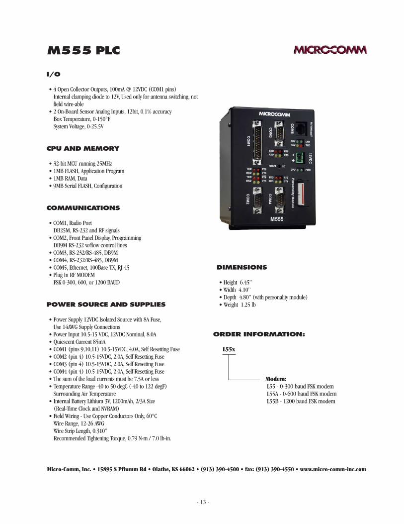
i/o
• 4 Open Collector Outputs, 100mA @ 12VDC (COM1 pins) Internal clamping diode to 12V, Used only for antenna switching, not
field wire-able• 2 On-Board Sensor Analog Inputs, 12bit, 0.1% accuracy Box Temperature, 0-150°F System Voltage, 0-25.5V
power sourCe and supplies
• Power Supply 12VDC Isolated Source with 8A Fuse, Use 14AWG Supply Connections• Power Input 10.5-15 VDC, 12VDC Nominal, 8.0A • Quiescent Current 85mA• COM1 (pins 9,10,11) 10.5-15VDC, 4.0A, Self Resetting Fuse• COM2 (pin 4) 10.5-15VDC, 2.0A, Self Resetting Fuse• COM3 (pin 4) 10.5-15VDC, 2.0A, Self Resetting Fuse• COM4 (pin 4) 10.5-15VDC, 2.0A, Self Resetting Fuse• The sum of the load currents must be 7.5A or less• Temperature Range -40 to 50 degC (-40 to 122 degF) Surrounding Air Temperature• Internal Battery Lithium 3V, 1200mAh, 2/3A Size (Real-Time Clock and NVRAM)• Field Wiring - Use Copper Conductors Only, 60°C Wire Range, 12-26 AWG Wire Strip Length, 0.310” Recommended Tightening Torque, 0.79 N-m / 7.0 lb-in.
Cpu and memory
• 32-bit MCU running 25MHz• 1MB FLASH, Application Program• 1MB RAM, Data• 9MB Serial FLASH, Configuration
CommuniCations
• COM1, Radio Port DB25M, RS-232 and RF signals• COM2, Front Panel Display, Programming DB9M RS-232 w/flow control lines • COM3, RS-232/RS-485, DB9M• COM4, RS-232/RS-485, DB9M• COM5, Ethernet, 100Base-TX, RJ-45• Plug In RF MODEM FSK 0-300, 600, or 1200 BAUD
dimensions
• Height 6.45”• Width 4.10”• Depth 4.80” (with personality module)• Weight 1.25 lb
- 14 -
M555 Installation Requirements
The installation of the M555 shall comply with all local and national fire and electrical codes, i.e. NFPA 70, National Electric Code. In order to provide proper fire and electrical shock protection, the M555 shall be powered from an isolated power source, use 14 AWG supply wiring provided with an 8A over current protection fuse. The fuse shall be located at the secondary of the source to properly protect the power supply secondary conductors. Field wiring shall use 60°C copper conductors. The wire should be stripped 0.310” and the terminal block tightened to the recommended torque, 0.79 N-m (7.0 lb-in.) DC control signals should be segregated from AC power and AC control wiring by using separate wire ducts and separate conduit.
The M555 is an open type device that requires an appropriate enclosure, suitable to the installation site. The surrounding air temperature of the M555 should not exceed 50°C (122°F).
- 15 -
M555 Lithium Battery Replacement
The internal lithium battery is a technician replaceable item.
Caution: the lithium battery used in this device may present a fire or chemical burn hazard if mistreated. Do not recharge, disassemble, heat above 100°C (212°F) or incinerate. Replace battery with Panasonic, Part No. BR-2/3A or Micro-Comm Part No. BAT-004-3 only. Use of another battery may present a risk of fire or explosion.
To replace the battery, remove power to the unit. Un-plug all of the terminal blocks and communications cables. Un-mount the unit and place it on a clean working surface. Remove the eight screws on the sides of the unit and lift the top cover from the mounting base. The battery is clipped into the battery holder labeled J8. Use a small blade screwdriver to pry the battery clip to the side and up. Then pry on the other side to fully remove the battery clip. At this point the battery is held in place by the battery holder contact spring force and it is simple to remove the battery with your fingers. Place a new battery in the battery holder, matching the orientation of the “+” and “-“ markings on the battery to the battery holder. Replace the battery clip by pressing it into place. Mate the top cover to the mounting base and re-install the eight screws. Re-mount the unit and plug all of the cables back into the unit.
Dispose of the battery properly. Keep away from children. Do not disassemble and do not dispose of in fire.
- 16 -
M1550 PLC
The M1550 is a fifth-generation Micro-Comm controller similar to the M1500 PLC, but with a faster processor, more memory, ethernet port and an additional COM4 port.
I/O capabilities:(4) Form C Relay Outputs(4) Open-collector outputs (COM1 pins used for radio switching)(8) Discrete inputs (contact closure), (2) high speed pulse, (6) low speed pulse(4) Analog Inputs (12bit, 0-20mA or 0-5volt dip switch selectable)(2) Additional 12bit analog inputs, Temperature, System Voltage(2) Analog Outputs (0-20mA)(3) RS-232 / RS-485 communication ports - COM1 25pin port for radio cable - COM2 9pin port normally used for the display module and programming - COM4 9pin port RS-232/RS-485(1) Ethernet 10/100baseT (RJ-45) port (1) RS-485 communication port
- COM3 is a 4-wire RS-485 port for I/O modules or PLC communication
- 17 -
M1550 Specifications and Sales Information
fully programmable with plug-in memory module
miCro-Comm, modbus rtu and allen-bradley df1 protoCols
optional front panel display & expandable i/o
radio, phone line, & fiber optiC CommuniCations
simultaneous rtu-rtu & Ctu-rtu CommuniCations
plug-in terminal bloCks
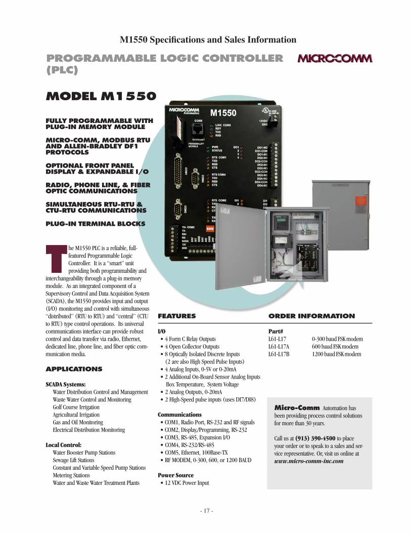
model m1550
t he M1550 PLC is a reliable, full-featured Programmable Logic Controller. It is a “smart” unit providing both programmability and
interchangeability through a plug-in memory module. As an integrated component of a Supervisory Control and Data Acquisition System (SCADA), the M1550 provides input and output (I/O) monitoring and control with simultaneous “distributed” (RTU to RTU) and “central” (CTU to RTU) type control operations. Its universal communications interface can provide robust control and data transfer via radio, Ethernet, dedicated line, phone line, and fiber optic com-munication media.
appliCations
SCADA Systems: Water Distribution Control and Management Waste Water Control and Monitoring Golf Course Irrigation Agricultural Irrigation Gas and Oil Monitoring Electrical Distribution Monitoring
Local Control: Water Booster Pump Stations Sewage Lift Stations Constant and Variable Speed Pump Stations Metering Stations Water and Waste Water Treatment Plants
features
I/O• 4 Form C Relay Outputs• 4 Open Collector Outputs• 8 Optically Isolated Discrete Inputs (2 are also High Speed Pulse Inputs)• 4 Analog Inputs, 0-5V or 0-20mA • 2 Additional On-Board Sensor Analog Inputs Box Temperature, System Voltage• 2 Analog Outputs, 0-20mA• 2 High-Speed pulse inputs (uses DI7/DI8)
Communications• COM1, Radio Port, RS-232 and RF signals• COM2, Display,/Programming, RS-232• COM3, RS-485, Expansion I/O• COM4, RS-232/RS-485• COM5, Ethernet, 100Base-TX• RF MODEM, 0-300, 600, or 1200 BAUD
Power Source• 12 VDC Power Input
order information
Part#L61-L17 0-300 baud FSK modemL61-L17A 600 baud FSK modemL61-L17B 1200 baud FSK modem
micro-Comm Automation has been providing process control solutions for more than 30 years.
Call us at (913) 390-4500 to place your order or to speak to a sales and ser-vice representative. Or, visit us online at www.micro-comm-inc.com
programmable logiC Controller (plC)
- 18 -
order information:
L61-xxxx
Modem: L17 - 0-300 baud FSK modem L17A - 0-600 baud FSK modem L17B - 1200 baud FSK modem
Micro-Comm, Inc. • 15895 S Pflumm Rd • Olathe, KS 66062 • (913) 390-4500 • fax: (913) 390-4550 • www.micro-comm-inc.com
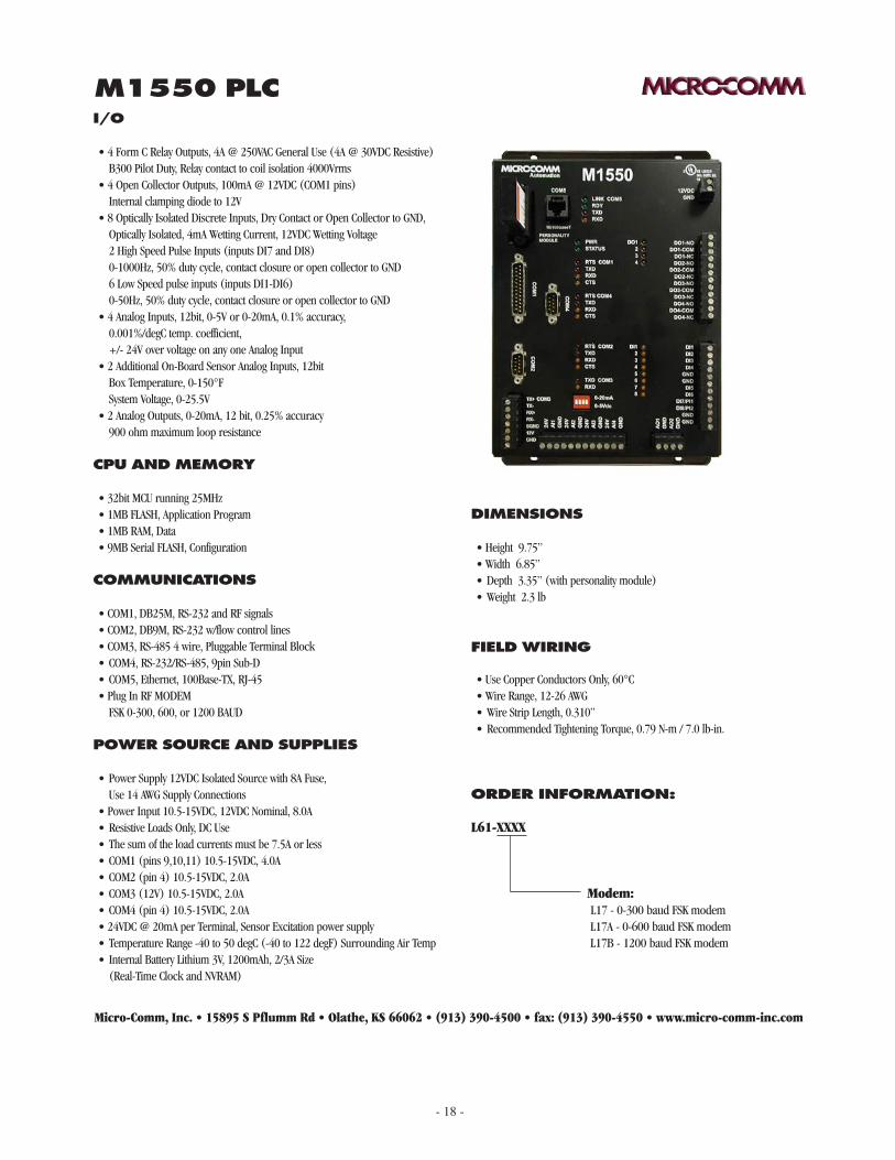
m1550 plCi/o
• 4 Form C Relay Outputs, 4A @ 250VAC General Use (4A @ 30VDC Resistive) B300 Pilot Duty, Relay contact to coil isolation 4000Vrms• 4 Open Collector Outputs, 100mA @ 12VDC (COM1 pins) Internal clamping diode to 12V• 8 Optically Isolated Discrete Inputs, Dry Contact or Open Collector to GND, Optically Isolated, 4mA Wetting Current, 12VDC Wetting Voltage 2 High Speed Pulse Inputs (inputs DI7 and DI8) 0-1000Hz, 50% duty cycle, contact closure or open collector to GND 6 Low Speed pulse inputs (inputs DI1-DI6) 0-50Hz, 50% duty cycle, contact closure or open collector to GND• 4 Analog Inputs, 12bit, 0-5V or 0-20mA, 0.1% accuracy, 0.001%/degC temp. coefficient, +/- 24V over voltage on any one Analog Input• 2 Additional On-Board Sensor Analog Inputs, 12bit Box Temperature, 0-150°F System Voltage, 0-25.5V• 2 Analog Outputs, 0-20mA, 12 bit, 0.25% accuracy 900 ohm maximum loop resistance
power sourCe and supplies
• Power Supply 12VDC Isolated Source with 8A Fuse, Use 14 AWG Supply Connections• Power Input 10.5-15VDC, 12VDC Nominal, 8.0A • Resistive Loads Only, DC Use• The sum of the load currents must be 7.5A or less• COM1 (pins 9,10,11) 10.5-15VDC, 4.0A• COM2 (pin 4) 10.5-15VDC, 2.0A• COM3 (12V) 10.5-15VDC, 2.0A• COM4 (pin 4) 10.5-15VDC, 2.0A• 24VDC @ 20mA per Terminal, Sensor Excitation power supply• Temperature Range -40 to 50 degC (-40 to 122 degF) Surrounding Air Temp• Internal Battery Lithium 3V, 1200mAh, 2/3A Size (Real-Time Clock and NVRAM)
Cpu and memory
• 32bit MCU running 25MHz• 1MB FLASH, Application Program• 1MB RAM, Data• 9MB Serial FLASH, Configuration
CommuniCations
• COM1, DB25M, RS-232 and RF signals• COM2, DB9M, RS-232 w/flow control lines • COM3, RS-485 4 wire, Pluggable Terminal Block• COM4, RS-232/RS-485, 9pin Sub-D• COM5, Ethernet, 100Base-TX, RJ-45• Plug In RF MODEM FSK 0-300, 600, or 1200 BAUD
dimensions
• Height 9.75”• Width 6.85”• Depth 3.35” (with personality module)• Weight 2.3 lb
field wiring
• Use Copper Conductors Only, 60°C• Wire Range, 12-26 AWG• Wire Strip Length, 0.310”• Recommended Tightening Torque, 0.79 N-m / 7.0 lb-in.
- 19 -
The installation of the M1550 shall comply with all local and national fire and electrical codes, i.e. NFPA 70, National Electric Code. In order to provide proper fire and electrical shock protection, the M1550 shall be powered from an isolated power source, use 14 AWG supply wiring provided with an 8A over current protection fuse. The fuse shall be located at the secondary of the source to properly protect the power supply secondary conductors.
Field wiring should use 60°C copper conductors. The pluggable terminal blocks will accept 12-26 AWG wire. The wire should be stripped 0.310” and the terminal block tightened to the recommended torque, 0.79 N-m (7.0 lb-in.) Use appropriate gauge wire for the control circuit loads. Minimum 22 AWG wire is recommended for the Discrete Inputs. Minimum 22 AWG, twisted, shielded wire is recommended for the Analog Inputs and Analog Outputs. 14 AWG wire is recommended for the Discrete (Relay) Outputs. DC control signals should be segregated from AC power and AC control wiring by using separate wire ducts and separate conduit.
The M1550 is an open type device that requires an appropriate enclosure, suitable to the installation site. The surrounding air temperature of the M1550 should not exceed 50°C (122°F).
M1550 Installation Requirements
- 20 -
M1550 Lithium Battery Replacement
The internal lithium battery is a technician replaceable item.
Caution: the lithium battery used in this device may present a fire or chemical burn hazard if mistreated. Do not recharge, disassemble, heat above 100°C (212°F) or incinerate. Replace battery with Panasonic, Part No. BR-2/3A or Micro-Comm Part No. BAT-004-3 only. Use of another battery may present a risk of fire or explosion.
To replace the battery, remove all power to the unit. Caution – power to the relay contacts may be sup-plied from other equipment. Un-plug all of the terminal blocks and communications cables. Un-mount the unit and remove the four screws on the sides of the unit. Place the unit on a clean working surface and lift the mounting base from the face plate. The battery is located in the center of the face plate, clipped into the battery holder labeled J15. Use a small blade screwdriver to pry the battery clip to the side and up. Then pry on the other side to fully remove the battery clip. At this point the battery is held in place by the battery holder contact spring force and it is simple to remove the battery with your fingers. Place a new battery in the battery holder, matching the orientation of the “+” and “-“ markings on the battery to the battery holder. Replace the battery clip by pressing it into place. Mate the mounting base to the face plate and re-install the four screws. Re-mount the unit and plug all of the cables back into the unit.
Dispose of the battery properly. Keep away from children. Do not disassemble and do not dispose of in fire.

- 21 -
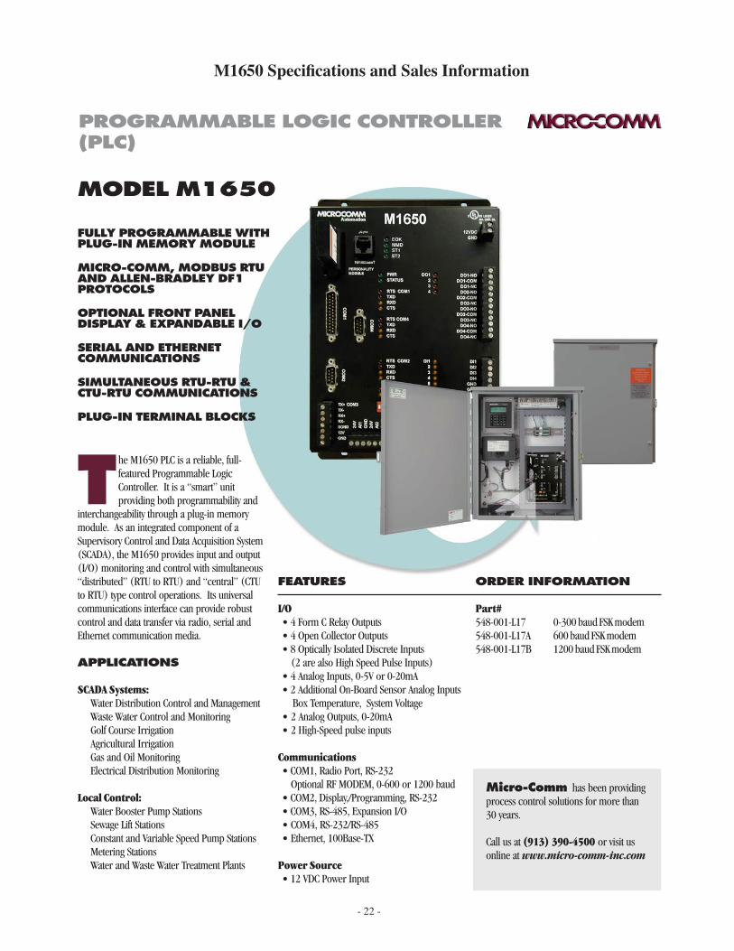
M1650, M655 and M1600 PLC
The M1650 and M655 are sixth-generation Micro-Comm controllers similar to the M1550/M555 PLCs, but with the additional of a built-in Ethernet coprocessor (uLynx) in place of the COM5 Ethernet found in the older PLCs. The new uLynx Ethernet module provides simultaneous master connections to other controllers as well as multiple slave connections utilitizing Micro-Comm CTU32, Modbus/TCP and Ethernet/IP protocols. It also includes a built-in web server for diagnostics.
The M1600 is identical to the M1650 except the Ethernet connection and coprocessor is not included.
- 22 -
M1650 Specifications and Sales Information
FULLY PROGRAMMABLE WITH PLUG-IN MEMORY MODULE
MICRO-COMM, MODBUS RTU AND ALLEN-BRADLEY DF1 PROTOCOLS
OPTIONAL FRONT PANEL DISPLAY & EXPANDABLE I/O
SERIAL AND ETHERNET COMMUNICATIONS
SIMULTANEOUS RTU-RTU & CTU-RTU COMMUNICATIONS
PLUG-IN TERMINAL BLOCKS
MODEL M1650
T he M1650 PLC is a reliable, full-featured Programmable Logic Controller. It is a “smart” unit providing both programmability and
interchangeability through a plug-in memory module. As an integrated component of a Supervisory Control and Data Acquisition System (SCADA), the M1650 provides input and output (I/O) monitoring and control with simultaneous “distributed” (RTU to RTU) and “central” (CTU to RTU) type control operations. Its universal communications interface can provide robust control and data transfer via radio, serial and Ethernet communication media.
APPLICATIONS
SCADA Systems: Water Distribution Control and Management Waste Water Control and Monitoring Golf Course Irrigation Agricultural Irrigation Gas and Oil Monitoring Electrical Distribution Monitoring
Local Control: Water Booster Pump Stations Sewage Lift Stations Constant and Variable Speed Pump Stations Metering Stations Water and Waste Water Treatment Plants
FEATURES
I/O• 4 Form C Relay Outputs• 4 Open Collector Outputs• 8 Optically Isolated Discrete Inputs (2 are also High Speed Pulse Inputs)• 4 Analog Inputs, 0-5V or 0-20mA • 2 Additional On-Board Sensor Analog Inputs Box Temperature, System Voltage• 2 Analog Outputs, 0-20mA• 2 High-Speed pulse inputs
Communications• COM1, Radio Port, RS-232 Optional RF MODEM, 0-600 or 1200 baud• COM2, Display,/Programming, RS-232• COM3, RS-485, Expansion I/O• COM4, RS-232/RS-485• Ethernet, 100Base-TX
Power Source• 12 VDC Power Input
ORDER INFORMATION
Part#548-001-L17 0-300 baud FSK modem548-001-L17A 600 baud FSK modem548-001-L17B 1200 baud FSK modem
Micro-Comm has been providing process control solutions for more than 30 years.
Call us at (913) 390-4500 or visit us online at www.micro-comm-inc.com
PROGRAMMABLE LOGIC CONTROLLER (PLC)
- 23 -
ORDER INFORMATION
548-001-XXXX
Modem: L17 - 0-300 baud FSK modem L17A - 0-600 baud FSK modem L17B - 1200 baud FSK modem
Micro-Comm, Inc. • 15895 S Pflumm Rd • Olathe, KS 66062 • (913) 390-4500 • fax: (913) 390-4550 • www.micro-comm-inc.com
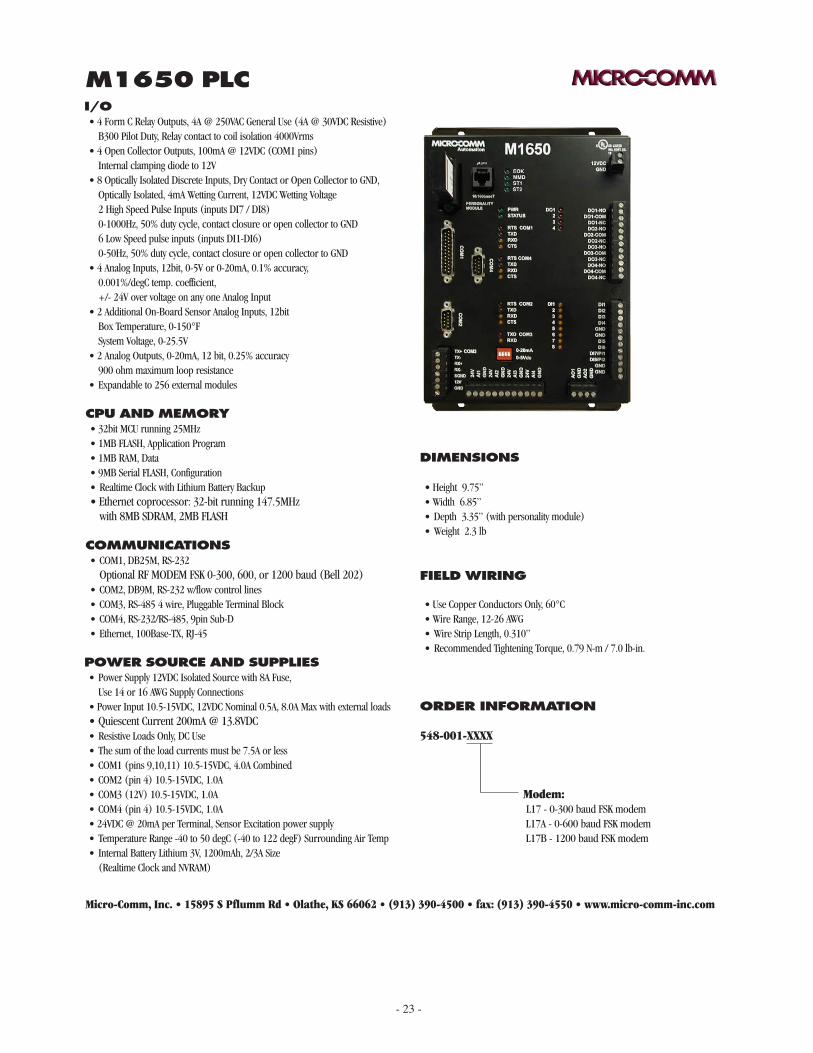
M1650 PLCI/O• 4 Form C Relay Outputs, 4A @ 250VAC General Use (4A @ 30VDC Resistive) B300 Pilot Duty, Relay contact to coil isolation 4000Vrms• 4 Open Collector Outputs, 100mA @ 12VDC (COM1 pins) Internal clamping diode to 12V• 8 Optically Isolated Discrete Inputs, Dry Contact or Open Collector to GND, Optically Isolated, 4mA Wetting Current, 12VDC Wetting Voltage 2 High Speed Pulse Inputs (inputs DI7 / DI8) 0-1000Hz, 50% duty cycle, contact closure or open collector to GND 6 Low Speed pulse inputs (inputs DI1-DI6) 0-50Hz, 50% duty cycle, contact closure or open collector to GND• 4 Analog Inputs, 12bit, 0-5V or 0-20mA, 0.1% accuracy, 0.001%/degC temp. coefficient, +/- 24V over voltage on any one Analog Input• 2 Additional On-Board Sensor Analog Inputs, 12bit Box Temperature, 0-150°F System Voltage, 0-25.5V• 2 Analog Outputs, 0-20mA, 12 bit, 0.25% accuracy 900 ohm maximum loop resistance• Expandable to 256 external modules
POWER SOURCE AND SUPPLIES• Power Supply 12VDC Isolated Source with 8A Fuse, Use 14 or 16 AWG Supply Connections• Power Input 10.5-15VDC, 12VDC Nominal 0.5A, 8.0A Max with external loads • Quiescent Current 200mA @ 13.8VDC• Resistive Loads Only, DC Use• The sum of the load currents must be 7.5A or less• COM1 (pins 9,10,11) 10.5-15VDC, 4.0A Combined• COM2 (pin 4) 10.5-15VDC, 1.0A• COM3 (12V) 10.5-15VDC, 1.0A• COM4 (pin 4) 10.5-15VDC, 1.0A• 24VDC @ 20mA per Terminal, Sensor Excitation power supply• Temperature Range -40 to 50 degC (-40 to 122 degF) Surrounding Air Temp• Internal Battery Lithium 3V, 1200mAh, 2/3A Size (Realtime Clock and NVRAM)
CPU AND MEMORY• 32bit MCU running 25MHz• 1MB FLASH, Application Program• 1MB RAM, Data• 9MB Serial FLASH, Configuration• Realtime Clock with Lithium Battery Backup• Ethernet coprocessor: 32-bit running 147.5MHz with 8MB SDRAM, 2MB FLASH
COMMUNICATIONS• COM1, DB25M, RS-232 Optional RF MODEM FSK 0-300, 600, or 1200 baud (Bell 202)• COM2, DB9M, RS-232 w/flow control lines • COM3, RS-485 4 wire, Pluggable Terminal Block• COM4, RS-232/RS-485, 9pin Sub-D• Ethernet, 100Base-TX, RJ-45
DIMENSIONS
• Height 9.75”• Width 6.85”• Depth 3.35” (with personality module)• Weight 2.3 lb
FIELD WIRING
• Use Copper Conductors Only, 60°C• Wire Range, 12-26 AWG• Wire Strip Length, 0.310”• Recommended Tightening Torque, 0.79 N-m / 7.0 lb-in.
- 24 -
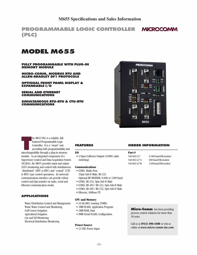
M655 Specifications and Sales Information
T he M655 PLC is a reliable, full-featured Programmable Logic Controller. It is a “smart” unit providing both programmability and
interchangeability through a plug-in memory module. As an integrated component of a Supervisory Control and Data Acquisition System (SCADA), the M655 provides input and output (I/O) monitoring and control with simultaneous “distributed” (RTU to RTU) and “central” (CTU to RTU) type control operations. Its universal communications interface can provide robust control and data transfer via radio, serial and Ethernet communication media.
APPLICATIONS
Water Distribution Control and Management Waste Water Control and Monitoring Golf Course Irrigation Agricultural Irrigation Gas and Oil Monitoring Electrical Distribution Monitoring
FULLY PROGRAMMABLE WITH PLUG-IN MEMORY MODULE
MICRO-COMM, MODBUS RTU AND ALLEN-BRADLEY DF1 PROTOCOLS
OPTIONAL FRONT PANEL DISPLAY & EXPANDABLE I/O
SERIAL AND ETHERNET COMMUNICATIONS
SIMULTANEOUS RTU-RTU & CTU-RTU COMMUNICATIONS
MODEL M655
FEATURES
I/O• 4 Open Collector Outputs (COM1 radio
switching)
Communications• COM1, Radio Port, 25pin Sub-D Male, RS-232 Optional RF MODEM, 0-600 or 1200 baud• COM2, RS-232, 9pin Sub-D Male• COM3, RS-485 / RS-232, 9pin Sub-D Male• COM4, RS-485 / RS-232, 9pin Sub-D Male• Ethernet, 100base-TX
CPU and Memory• 32-bit MCU running 25MHz• 1MB FLASH, Application Program• 1MB RAM, Data• 9MB Serial FLASH, Configuration
Power Source• 12 VDC Power Input
ORDER INFORMATION
Part # 548-002-L17 0-300 baud FSK modem 548-002-L17A 600 baud FSK modem 548-002-L17B 1200 baud FSK modem
Micro-Comm has been providing process control solutions for more than 30 years.
Call us at (913) 390-4500 or visit us online at www.micro-comm-inc.com
PROGRAMMABLE LOGIC CONTROLLER (PLC)
- 25 -
ORDER INFORMATION
548-002-XXXX
Modem: L17 - 0-300 baud FSK modem L17A - 0-600 baud FSK modem L17B - 1200 baud FSK modem
Micro-Comm, Inc. • 15895 S Pflumm Rd • Olathe, KS 66062 • (913) 390-4500 • fax: (913) 390-4550 • www.micro-comm-inc.com
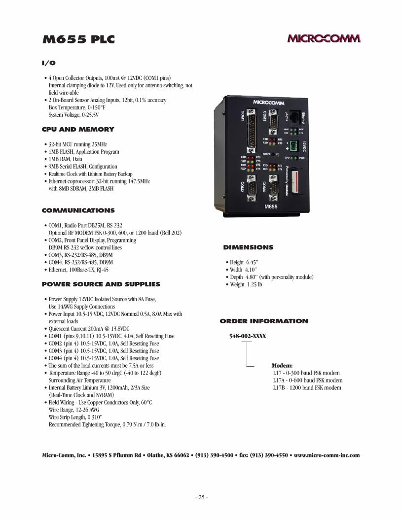
M655 PLC
I/O
• 4 Open Collector Outputs, 100mA @ 12VDC (COM1 pins) Internal clamping diode to 12V, Used only for antenna switching, not
field wire-able• 2 On-Board Sensor Analog Inputs, 12bit, 0.1% accuracy Box Temperature, 0-150°F System Voltage, 0-25.5V
POWER SOURCE AND SUPPLIES
• Power Supply 12VDC Isolated Source with 8A Fuse, Use 14AWG Supply Connections• Power Input 10.5-15 VDC, 12VDC Nominal 0.5A, 8.0A Max with
external loads• Quiescent Current 200mA @ 13.8VDC• COM1 (pins 9,10,11) 10.5-15VDC, 4.0A, Self Resetting Fuse• COM2 (pin 4) 10.5-15VDC, 1.0A, Self Resetting Fuse• COM3 (pin 4) 10.5-15VDC, 1.0A, Self Resetting Fuse• COM4 (pin 4) 10.5-15VDC, 1.0A, Self Resetting Fuse• The sum of the load currents must be 7.5A or less• Temperature Range -40 to 50 degC (-40 to 122 degF) Surrounding Air Temperature• Internal Battery Lithium 3V, 1200mAh, 2/3A Size (Real-Time Clock and NVRAM)• Field Wiring - Use Copper Conductors Only, 60°C Wire Range, 12-26 AWG Wire Strip Length, 0.310” Recommended Tightening Torque, 0.79 N-m / 7.0 lb-in.
CPU AND MEMORY
• 32-bit MCU running 25MHz• 1MB FLASH, Application Program• 1MB RAM, Data• 9MB Serial FLASH, Configuration• Realtime Clock with Lithium Battery Backup• Ethernet coprocessor: 32-bit running 147.5MHz with 8MB SDRAM, 2MB FLASH
COMMUNICATIONS
• COM1, Radio Port DB25M, RS-232 Optional RF MODEM FSK 0-300, 600, or 1200 baud (Bell 202)• COM2, Front Panel Display, Programming DB9M RS-232 w/flow control lines • COM3, RS-232/RS-485, DB9M• COM4, RS-232/RS-485, DB9M• Ethernet, 100Base-TX, RJ-45
DIMENSIONS
• Height 6.45”• Width 4.10”• Depth 4.80” (with personality module)• Weight 1.25 lb
- 26 -
FULLY PROGRAMMABLE WITH PLUG-IN MEMORY MODULE
MICRO-COMM, MODBUS RTU AND ALLEN-BRADLEY DF1 PROTOCOLS
OPTIONAL FRONT PANEL DISPLAY & EXPANDABLE I/O
SIMULTANEOUS RTU-RTU & CTU-RTU COMMUNICATIONS
PLUG-IN TERMINAL BLOCKS
MODEL M1600
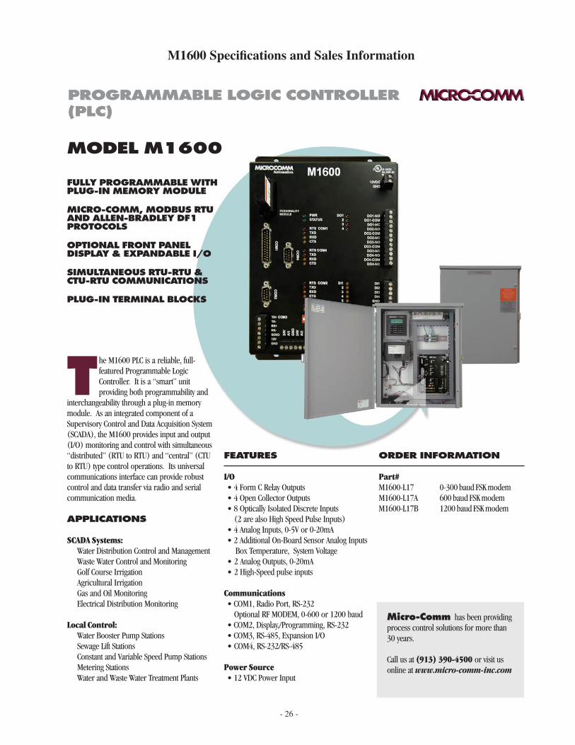
T he M1600 PLC is a reliable, full-featured Programmable Logic Controller. It is a “smart” unit providing both programmability and
interchangeability through a plug-in memory module. As an integrated component of a Supervisory Control and Data Acquisition System (SCADA), the M1600 provides input and output (I/O) monitoring and control with simultaneous “distributed” (RTU to RTU) and “central” (CTU to RTU) type control operations. Its universal communications interface can provide robust control and data transfer via radio and serial communication media.
APPLICATIONS
SCADA Systems: Water Distribution Control and Management Waste Water Control and Monitoring Golf Course Irrigation Agricultural Irrigation Gas and Oil Monitoring Electrical Distribution Monitoring
Local Control: Water Booster Pump Stations Sewage Lift Stations Constant and Variable Speed Pump Stations Metering Stations Water and Waste Water Treatment Plants
FEATURES
I/O• 4 Form C Relay Outputs• 4 Open Collector Outputs• 8 Optically Isolated Discrete Inputs (2 are also High Speed Pulse Inputs)• 4 Analog Inputs, 0-5V or 0-20mA • 2 Additional On-Board Sensor Analog Inputs Box Temperature, System Voltage• 2 Analog Outputs, 0-20mA• 2 High-Speed pulse inputs
Communications• COM1, Radio Port, RS-232 Optional RF MODEM, 0-600 or 1200 baud• COM2, Display,/Programming, RS-232• COM3, RS-485, Expansion I/O• COM4, RS-232/RS-485
Power Source• 12 VDC Power Input
ORDER INFORMATION
Part#M1600-L17 0-300 baud FSK modemM1600-L17A 600 baud FSK modemM1600-L17B 1200 baud FSK modem
Micro-Comm has been providing process control solutions for more than 30 years.
Call us at (913) 390-4500 or visit us online at www.micro-comm-inc.com
PROGRAMMABLE LOGIC CONTROLLER (PLC)
M1600 Specifications and Sales Information
- 27 -
ORDER INFORMATION
M1600 - XXXX
Modem: L17 - 0-300 baud FSK modem L17A - 0-600 baud FSK modem L17B - 1200 baud FSK modem
Micro-Comm, Inc. • 15895 S Pflumm Rd • Olathe, KS 66062 • (913) 390-4500 • fax: (913) 390-4550 • www.micro-comm-inc.com
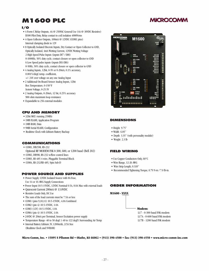
M1600 PLCI/O• 4 Form C Relay Outputs, 4A @ 250VAC General Use (4A @ 30VDC Resistive) B300 Pilot Duty, Relay contact to coil isolation 4000Vrms• 4 Open Collector Outputs, 100mA @ 12VDC (COM1 pins) Internal clamping diode to 12V• 8 Optically Isolated Discrete Inputs, Dry Contact or Open Collector to GND, Optically Isolated, 4mA Wetting Current, 12VDC Wetting Voltage 2 High Speed Pulse Inputs (inputs DI7 / DI8) 0-1000Hz, 50% duty cycle, contact closure or open collector to GND 6 Low Speed pulse inputs (inputs DI1-DI6) 0-50Hz, 50% duty cycle, contact closure or open collector to GND• 4 Analog Inputs, 12bit, 0-5V or 0-20mA, 0.1% accuracy, 0.001%/degC temp. coefficient, +/- 24V over voltage on any one Analog Input• 2 Additional On-Board Sensor Analog Inputs, 12bit Box Temperature, 0-150°F System Voltage, 0-25.5V• 2 Analog Outputs, 0-20mA, 12 bit, 0.25% accuracy 900 ohm maximum loop resistance• Expandable to 256 external modules
POWER SOURCE AND SUPPLIES• Power Supply 12VDC Isolated Source with 8A Fuse, Use 14 or 16 AWG Supply Connections• Power Input 10.5-15VDC, 12VDC Nominal 0.5A, 8.0A Max with external loads • Quiescent Current 200mA @ 13.8VDC• Resistive Loads Only, DC Use• The sum of the load currents must be 7.5A or less• COM1 (pins 9,10,11) 10.5-15VDC, 4.0A Combined• COM2 (pin 4) 10.5-15VDC, 1.0A• COM3 (12V) 10.5-15VDC, 1.0A• COM4 (pin 4) 10.5-15VDC, 1.0A• 24VDC @ 20mA per Terminal, Sensor Excitation power supply• Temperature Range -40 to 50 degC (-40 to 122 degF) Surrounding Air Temp• Internal Battery Lithium 3V, 1200mAh, 2/3A Size (Realtime Clock and NVRAM)
CPU AND MEMORY• 32bit MCU running 25MHz• 1MB FLASH, Application Program• 1MB RAM, Data• 9MB Serial FLASH, Configuration• Realtime Clock with Lithium Battery Backup
COMMUNICATIONS• COM1, DB25M, RS-232 Optional RF MODEM FSK 0-300, 600, or 1200 baud (Bell 202)• COM2, DB9M, RS-232 w/flow control lines • COM3, RS-485 4 wire, Pluggable Terminal Block• COM4, RS-232/RS-485, 9pin Sub-D
DIMENSIONS
• Height 9.75”• Width 6.85”• Depth 3.35” (with personality module)• Weight 2.3 lb
FIELD WIRING
• Use Copper Conductors Only, 60°C• Wire Range, 12-26 AWG• Wire Strip Length, 0.310”• Recommended Tightening Torque, 0.79 N-m / 7.0 lb-in.
- 28 -
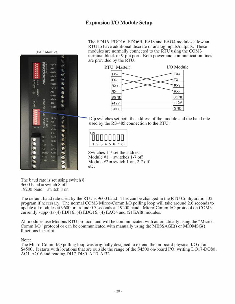
Expansion I/O Module Setup
Dip switches set both the address of the module and the baud rate used by the RS-485 connection to the RTU.
The EDI16, EDO16, EDO6R, EAI8 and EAO4 modules allow an RTU to have additional discrete or analog inputs/outputs. These modules are normally connected to the RTU using the COM3 terminal block or 9-pin port. Both power and communication lines are provided by the RTU.
1 2 3 4 5 6 7 8
ON
TX+TX-RX+RX-SGND+12VGND
RTU (Master)TX+TX-RX+RX-SGND+12VGND
I/O Module
Switches 1-7 set the address:Module #1 = switches 1-7 offModule #2 = switch 1 on, 2-7 offetc.
The baud rate is set using switch 8:9600 baud = switch 8 off19200 baud = switch 8 on
The default baud rate used by the RTU is 9600 baud. This can be changed in the RTU Configuration 32 program if necessary. The normal COM3 Mirco-Comm I/O polling loop will take around 2.6 seconds to update all modules at 9600 or around 0.7 seconds at 19200 baud. Micro-Comm I/O protocol on COM3 currently supports (4) EDI16, (4) EDO16, (4) EAO4 and (2) EAI8 modules.
All modules use Modbus RTU protocol and will be communicated with automatically using the “Micro-Comm I/O” protocol or can be communicated with manually using the MESSAGE() or MIOMSG() functions in script.
Note:The Micro-Comm I/O polling loop was originally designed to extend the on-board physical I/O of an S4500. It starts with locations that are outside the range of the S4500 on-board I/O: writing DO17-DO80, AO1-AO16 and reading DI17-DI80, AI17-AI32.
(EAI8 Module)
- 29 -
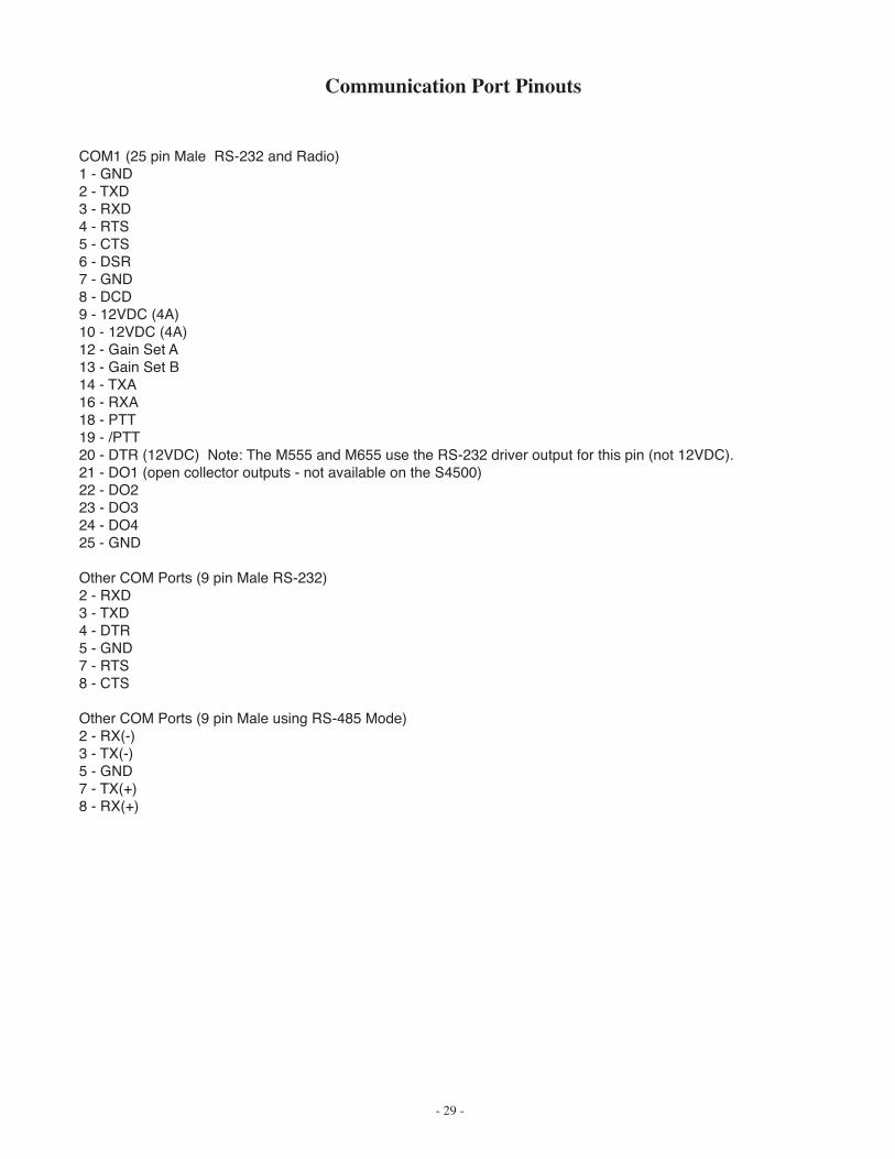
COM1 (25 pin Male RS-232 and Radio)1 - GND2 - TXD3 - RXD4 - RTS5 - CTS6 - DSR7 - GND8 - DCD9 - 12VDC (4A)10 - 12VDC (4A)12 - Gain Set A13 - Gain Set B14 - TXA16 - RXA18 - PTT19 - /PTT20 - DTR (12VDC) Note: The M555 and M655 use the RS-232 driver output for this pin (not 12VDC).21 - DO1 (open collector outputs - not available on the S4500)22 - DO223 - DO324 - DO425 - GND
Other COM Ports (9 pin Male RS-232)2 - RXD3 - TXD4 - DTR5 - GND7 - RTS8 - CTS
Other COM Ports (9 pin Male using RS-485 Mode)2 - RX(-)3 - TX(-)5 - GND7 - TX(+)8 - RX(+)
Communication Port Pinouts
- 30 -
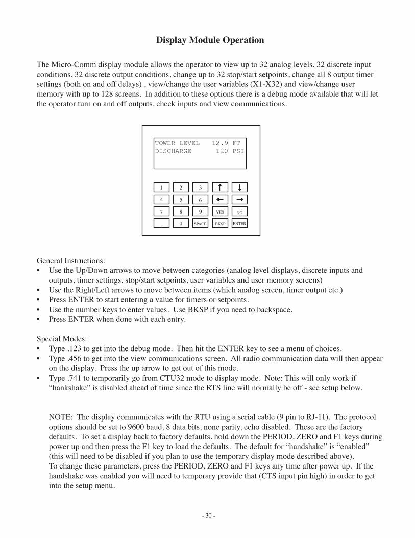
Display Module Operation
The Micro-Comm display module allows the operator to view up to 32 analog levels, 32 discrete input conditions, 32 discrete output conditions, change up to 32 stop/start setpoints, change all 8 output timer settings (both on and off delays) , view/change the user variables (X1-X32) and view/change user memory with up to 128 screens. In addition to these options there is a debug mode available that will let the operator turn on and off outputs, check inputs and view communications.
General Instructions:• Use the Up/Down arrows to move between categories (analog level displays, discrete inputs and
outputs, timer settings, stop/start setpoints, user variables and user memory screens)• Use the Right/Left arrows to move between items (which analog screen, timer output etc.)• Press ENTER to start entering a value for timers or setpoints.• Use the number keys to enter values. Use BKSP if you need to backspace.• Press ENTER when done with each entry.
Special Modes:• Type .123 to get into the debug mode. Then hit the ENTER key to see a menu of choices.• Type .456 to get into the view communications screen. All radio communication data will then appear
on the display. Press the up arrow to get out of this mode.• Type .741 to temporarily go from CTU32 mode to display mode. Note: This will only work if
“hankshake” is disabled ahead of time since the RTS line will normally be off - see setup below.
NOTE: The display communicates with the RTU using a serial cable (9 pin to RJ-11). The protocol options should be set to 9600 baud, 8 data bits, none parity, echo disabled. These are the factory defaults. To set a display back to factory defaults, hold down the PERIOD, ZERO and F1 keys during power up and then press the F1 key to load the defaults. The default for “handshake” is “enabled” (this will need to be disabled if you plan to use the temporary display mode described above).
To change these parameters, press the PERIOD, ZERO and F1 keys any time after power up. If the handshake was enabled you will need to temporary provide that (CTS input pin high) in order to get into the setup menu.
1 2 3
4 5 6
7 8 9
. 0 SPACE BKSP ENTER
NOYES
TOWER LEVEL 12.9 FTDISCHARGE 120 PSI
- 31 -
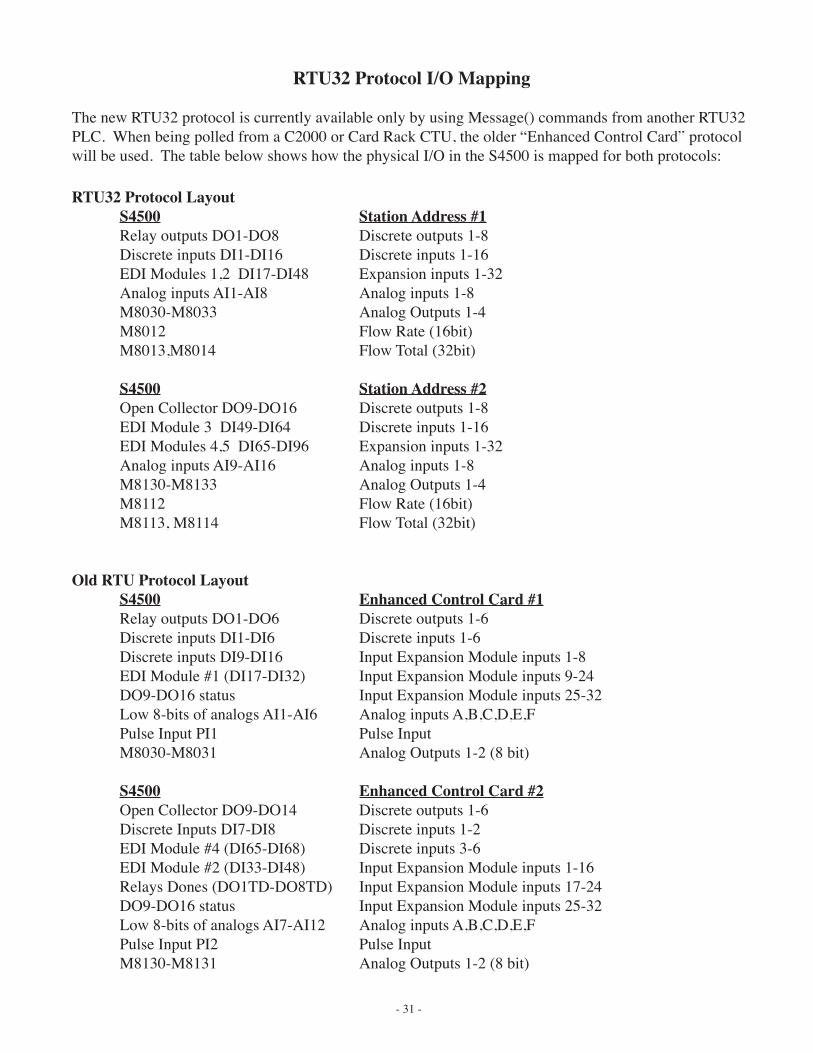
RTU32 Protocol I/O Mapping
The new RTU32 protocol is currently available only by using Message() commands from another RTU32 PLC. When being polled from a C2000 or Card Rack CTU, the older “Enhanced Control Card” protocol will be used. The table below shows how the physical I/O in the S4500 is mapped for both protocols:
RTU32 Protocol LayoutS4500 Station Address #1Relay outputs DO1-DO8 Discrete outputs 1-8Discrete inputs DI1-DI16 Discrete inputs 1-16EDI Modules 1,2 DI17-DI48 Expansion inputs 1-32Analog inputs AI1-AI8 Analog inputs 1-8M8030-M8033 Analog Outputs 1-4M8012 Flow Rate (16bit)M8013,M8014 Flow Total (32bit)
S4500 Station Address #2Open Collector DO9-DO16 Discrete outputs 1-8EDI Module 3 DI49-DI64 Discrete inputs 1-16EDI Modules 4,5 DI65-DI96 Expansion inputs 1-32Analog inputs AI9-AI16 Analog inputs 1-8M8130-M8133 Analog Outputs 1-4M8112 Flow Rate (16bit)M8113, M8114 Flow Total (32bit)
Old RTU Protocol LayoutS4500 Enhanced Control Card #1Relay outputs DO1-DO6 Discrete outputs 1-6Discrete inputs DI1-DI6 Discrete inputs 1-6Discrete inputs DI9-DI16 Input Expansion Module inputs 1-8EDI Module #1 (DI17-DI32) Input Expansion Module inputs 9-24DO9-DO16 status Input Expansion Module inputs 25-32Low 8-bits of analogs AI1-AI6 Analog inputs A,B,C,D,E,FPulse Input PI1 Pulse InputM8030-M8031 Analog Outputs 1-2 (8 bit)
S4500 Enhanced Control Card #2Open Collector DO9-DO14 Discrete outputs 1-6Discrete Inputs DI7-DI8 Discrete inputs 1-2EDI Module #4 (DI65-DI68) Discrete inputs 3-6EDI Module #2 (DI33-DI48) Input Expansion Module inputs 1-16Relays Dones (DO1TD-DO8TD) Input Expansion Module inputs 17-24DO9-DO16 status Input Expansion Module inputs 25-32Low 8-bits of analogs AI7-AI12 Analog inputs A,B,C,D,E,FPulse Input PI2 Pulse InputM8130-M8131 Analog Outputs 1-2 (8 bit)
- 32 -
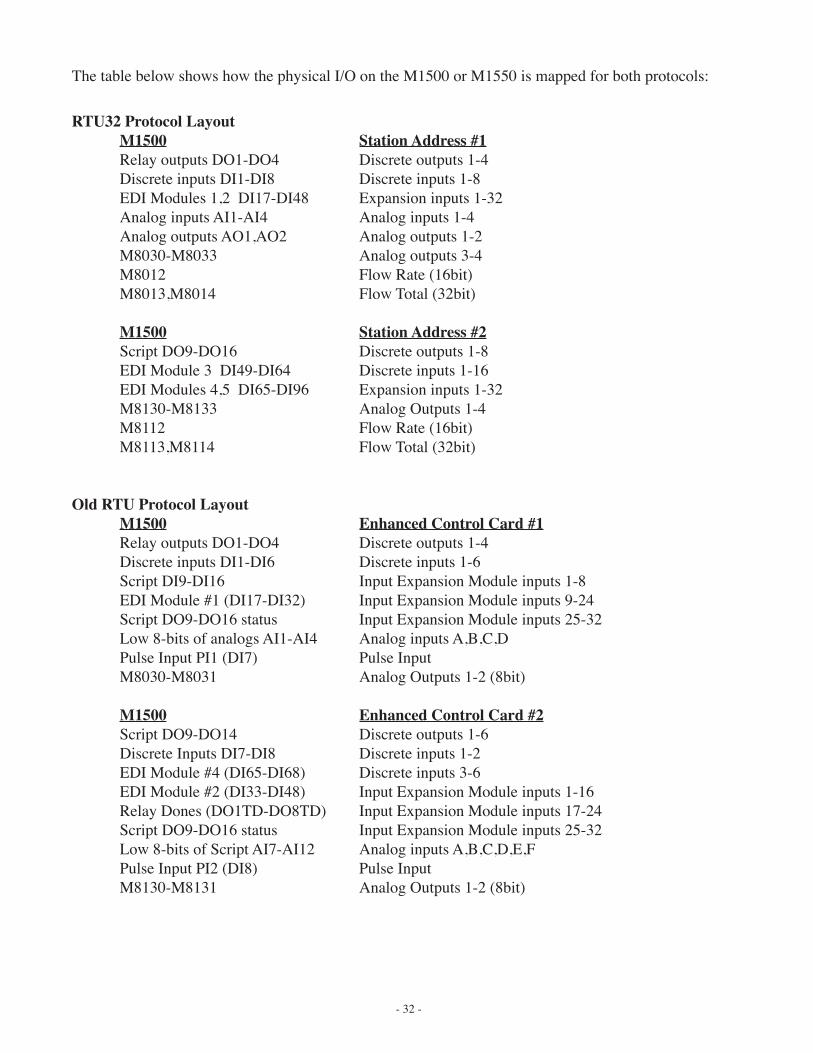
RTU32 Protocol LayoutM1500 Station Address #1Relay outputs DO1-DO4 Discrete outputs 1-4Discrete inputs DI1-DI8 Discrete inputs 1-8EDI Modules 1,2 DI17-DI48 Expansion inputs 1-32Analog inputs AI1-AI4 Analog inputs 1-4Analog outputs AO1,AO2 Analog outputs 1-2M8030-M8033 Analog outputs 3-4M8012 Flow Rate (16bit)M8013,M8014 Flow Total (32bit)
M1500 Station Address #2Script DO9-DO16 Discrete outputs 1-8EDI Module 3 DI49-DI64 Discrete inputs 1-16EDI Modules 4,5 DI65-DI96 Expansion inputs 1-32M8130-M8133 Analog Outputs 1-4M8112 Flow Rate (16bit)M8113,M8114 Flow Total (32bit)
Old RTU Protocol LayoutM1500 Enhanced Control Card #1Relay outputs DO1-DO4 Discrete outputs 1-4Discrete inputs DI1-DI6 Discrete inputs 1-6Script DI9-DI16 Input Expansion Module inputs 1-8EDI Module #1 (DI17-DI32) Input Expansion Module inputs 9-24Script DO9-DO16 status Input Expansion Module inputs 25-32Low 8-bits of analogs AI1-AI4 Analog inputs A,B,C,DPulse Input PI1 (DI7) Pulse InputM8030-M8031 Analog Outputs 1-2 (8bit)
M1500 Enhanced Control Card #2Script DO9-DO14 Discrete outputs 1-6Discrete Inputs DI7-DI8 Discrete inputs 1-2EDI Module #4 (DI65-DI68) Discrete inputs 3-6EDI Module #2 (DI33-DI48) Input Expansion Module inputs 1-16Relay Dones (DO1TD-DO8TD) Input Expansion Module inputs 17-24Script DO9-DO16 status Input Expansion Module inputs 25-32Low 8-bits of Script AI7-AI12 Analog inputs A,B,C,D,E,FPulse Input PI2 (DI8) Pulse InputM8130-M8131 Analog Outputs 1-2 (8bit)
The table below shows how the physical I/O on the M1500 or M1550 is mapped for both protocols:
- 33 -
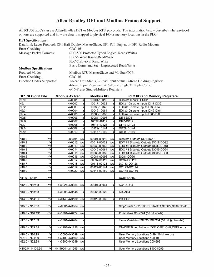
Allen-Bradley DF1 and Modbus Protocol Support
All RTU32 PLCs can use Allen-Bradley DF1 or Modbus RTU protocols. The information below describes what protocol options are supported and how the data is mapped to physical I/O or memory locations in the PLC:
DF1 SLC-500 File Modbus 4x Reg Modbus I/O PLC I/O and Memory RegistersN9:0 r 4x0001 r 10001-10016 r Discrete Inputs DI1-DI16
N9:1 r 4x0002 r 10017-10032 r EDI #1 Discrete Inputs DI17-DI32
N9:2 r 4x0003 r 10033-10048 r EDI #2 Discrete Inputs DI33-DI48
N9:3 r 4x0004 r 10049-10064 r EDI #3 Discrete Inputs DI49-DI64
N9:4 r 4x0005 r 10065-10080 r EDI #4 Discrete Inputs DI65-DI80
N9:5 r 4x0006 r 10081-10096 r DI81-DI96
N9:6 r 4x0007 r 10097-10112 r DI97-DI112
N9:7 r 4x0008 r 10113-10128 r DI113-DI128
N9:8 r 4x0009 r 10129-10144 r DI129-DI144
N9:9 r 4x0010 r 10145-10160 r DI145-DI160
N10:0 r/w 4x0011 r/w 00001-00016 r/w Discrete Outputs DO1-DO16
N10:1 r/w 4x0012 r/w 00017-00032 r/w EDO #1 Discrete Outputs DO17-DO32
N10:2 r/w 4x0013 r/w 00033-00048 r/w EDO #2 Discrete Outputs DO33-DO48
N10:3 r/w 4x0014 r/w 00049-00064 r/w EDO #3 Discrete Outputs DO49-DO64
N10:4 r/w 4x0015 r/w 00065-00080 r/w EDO #4 Discrete Outputs DO65-DO80
N10:5 r/w 4x0016 r/w 00081-00096 r/w DO81-DO96
N10:6 r/w 4x0017 r/w 00097-00112 r/w DO97-DO112
N10:7 r/w 4x0018 r/w 00113-00128 r/w DO113-DO128
N10:8 r/w 4x0019 r/w 00129-00144 r/w DO129-DO144
N10:9 r/w 4x0020 r/w 00145-00160 r/w DO145-DO160
N11:0 – N11:4 r/w DO81-DO160
N12:0 - N12:63 r/w 4x0021-4x0084 r/w 30001-30064 r AO1-AO64
N13:0 - N13:63 r 4x0085-4x0148 r 30065-30128 r AI1-AI64
N14:0 - N14:31 r/w 4x0149-4x0180 r/w 30129-30160 r PI1-PI32
N15:0 - N15:63 r/w 4x0601-4x0664 r/w Stop/Starts 1-32 STOP1,START1,STOP2,START2 etc.
N16:0 - N16:191 r/w 4x0201-4x0424 r/w X Variables X1-X224 (16 bit words)
N17:0 - N17:63 r 4x0701-4x0764 r Timer Variables TSEC1-TSEC64 (16 bit @ 1sec/bit)
N19:0 - N19:15 r/w 4x1201-4x1216 r/w ON/OFF Timer Settings (ON1,OFF1,ON2,OFF2 etc.)
N20:0 - N20:99 r/w 4x3000-4x3099 r/w User Memory Locations 0-99 (16 bit words)
N21:0 - N21:99 r/w 4x3100-4x3199 r/w User Memory Locations 100-199
N22:0 - N22:99 r/w 4x3200-4x3299 r/w User Memory Locations 200-299
… … …
N109:0 - N109:99 r/w 4x11900-4x11999 r/w User Memory Locations 8900-8999
Modbus SpecificationsProtocol Mode: Modbus RTU Master/Slave and Modbus/TCPError Checking: CRC-16Function Codes Supported: 1-Read Coil Status, 2-Read Input Status, 3-Read Holding Registers, 4-Read Input Registers, 5/15-Force Single/Multiple Coils, 6/16-Preset Single/Multiple Registers
DF1 SpecificationsData Link Layer Protocol: DF1 Half-Duplex Master/Slave, DF1 Full-Duplex or DF1 Radio ModemError Checking: CRC-16Message Packet Formats: SLC-500 Protected Typed Logical Reads/Writes PLC-5 Word Range Read/Write PLC-2 Physical Read/Write Basic Command Set - Unprotected Read/Write
- 34 -
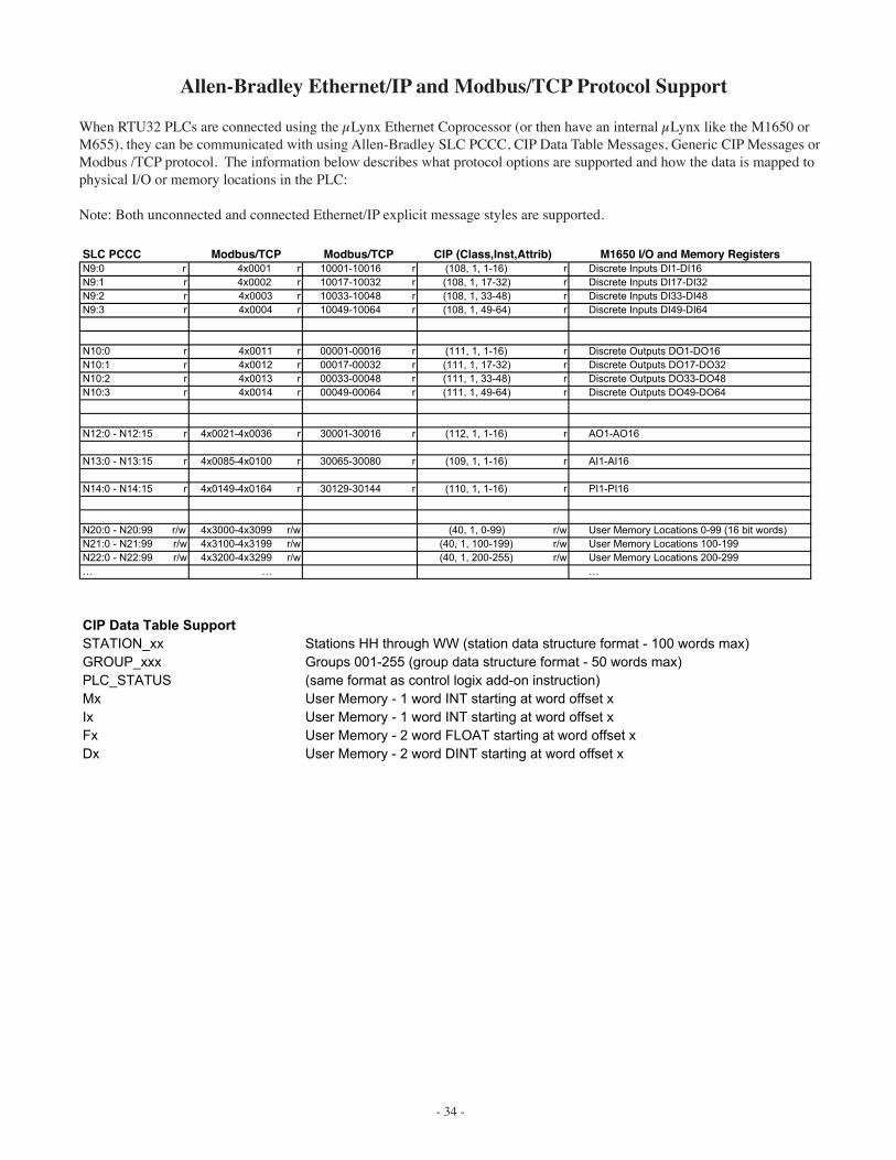
Allen-Bradley Ethernet/IP and Modbus/TCP Protocol Support
When RTU32 PLCs are connected using the µLynx Ethernet Coprocessor (or then have an internal µLynx like the M1650 or M655), they can be communicated with using Allen-Bradley SLC PCCC, CIP Data Table Messages, Generic CIP Messages or Modbus /TCP protocol. The information below describes what protocol options are supported and how the data is mapped to physical I/O or memory locations in the PLC:
Note: Both unconnected and connected Ethernet/IP explicit message styles are supported.
N9:0 r 4x0001 r 10001-10016 r (108, 1, 1-16) r Discrete Inputs DI1-DI16N9:1 r 4x0002 r 10017-10032 r (108, 1, 17-32) r Discrete Inputs DI17-DI32N9:2 r 4x0003 r 10033-10048 r (108, 1, 33-48) r Discrete Inputs DI33-DI48N9:3 r 4x0004 r 10049-10064 r (108, 1, 49-64) r Discrete Inputs DI49-DI64
N10:0 r 4x0011 r 00001-00016 r (111, 1, 1-16) r Discrete Outputs DO1-DO16N10:1 r 4x0012 r 00017-00032 r (111, 1, 17-32) r Discrete Outputs DO17-DO32N10:2 r 4x0013 r 00033-00048 r (111, 1, 33-48) r Discrete Outputs DO33-DO48N10:3 r 4x0014 r 00049-00064 r (111, 1, 49-64) r Discrete Outputs DO49-DO64
N12:0 - N12:15 r 4x0021-4x0036 r 30001-30016 r (112, 1, 1-16) r AO1-AO16
N13:0 - N13:15 r 4x0085-4x0100 r 30065-30080 r (109, 1, 1-16) r AI1-AI16
N14:0 - N14:15 r 4x0149-4x0164 r 30129-30144 r (110, 1, 1-16) r PI1-PI16
N20:0 - N20:99 r/w 4x3000-4x3099 r/w (40, 1, 0-99) r/w User Memory Locations 0-99 (16 bit words)N21:0 - N21:99 r/w 4x3100-4x3199 r/w (40, 1, 100-199) r/w User Memory Locations 100-199N22:0 - N22:99 r/w 4x3200-4x3299 r/w (40, 1, 200-255) r/w User Memory Locations 200-299… … …
CIP Data Table SupportSTATION_xx Stations HH through WW (station data structure format - 100 words max)GROUP_xxx Groups 001-255 (group data structure format - 50 words max)PLC_STATUS (same format as control logix add-on instruction)Mx User Memory - 1 word INT starting at word offset xIx User Memory - 1 word INT starting at word offset xFx User Memory - 2 word FLOAT starting at word offset xDx User Memory - 2 word DINT starting at word offset x
SLC PCCC Modbus/TCP Modbus/TCP M1650 I/O and Memory RegistersCIP (Class,Inst,Attrib)
- 35 -
Program Installation
A new version of RTU Configuration is required for programming the S4500 and later 32 bit PLCs. For lack of a better name, this new program is called “RTU Configuration 32”. Throughout this manual the program will be called “RTU Configuration 32” or “RTU Config”.
RTU Configuration 32 currently runs on Windows 7 Pro and later, Linux and Mac OS X 10.7 and later.
To Install the Windows version, follow the steps below:
When upgrading to a new version of the program, go to the Control Panels in Windows and double-click on Add/Remove Programs. Look through the list and remove any old versions of RTU Configuration.
1) Insert the CD into the CD-ROM Drive or download the setup program.2) RUN the SETUP program located on the CD-ROM.3) Follow the prompts and do a typical install.4) After installation, the program icon will appear in the Start menu’s Program list.
When running the configuration program for the first time you will need to look at the serial port setup screen to make sure you have the correct COM port number selected. The port setup is located in the program’s “Edit - Preferences...” menu. Connection to the PLC is by means of a Null-modem cable from the computer’s RS-232 port to the PLC’s COM2 port (display port).
RTU Configuration 32
- 36 -
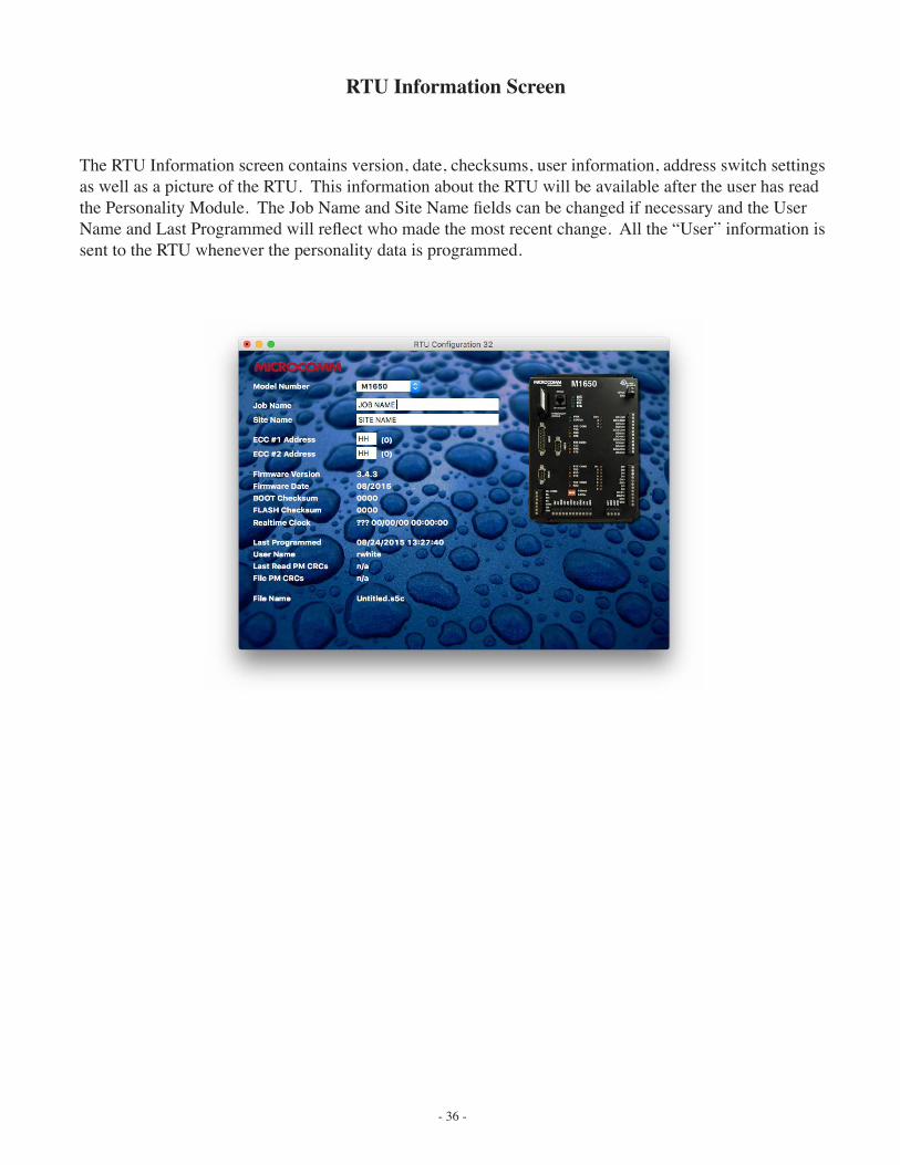
RTU Information Screen
The RTU Information screen contains version, date, checksums, user information, address switch settings as well as a picture of the RTU. This information about the RTU will be available after the user has read the Personality Module. The Job Name and Site Name fields can be changed if necessary and the User Name and Last Programmed will reflect who made the most recent change. All the “User” information is sent to the RTU whenever the personality data is programmed.
- 37 -
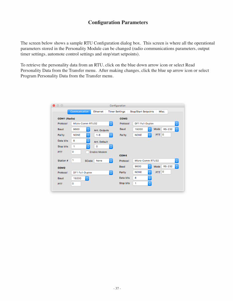
Configuration Parameters
The screen below shows a sample RTU Configuration dialog box. This screen is where all the operational parameters stored in the Personality Module can be changed (radio communications parameters, output timer settings, automote control settings and stop/start setpoints).
To retrieve the personality data from an RTU, click on the blue down arrow icon or select Read Personality Data from the Transfer menu. After making changes, click the blue up arrow icon or select Program Personality Data from the Transfer menu.
- 38 -
RTU Configuration Parameters
Model Number The model of the RTU being configured is selected and shown here.
Protocol The protocol selection for the radio communications port (COM1). Options include Micro-Comm RTU32, DF1 Half-Duplex Slave, DF1 Half-Duplex Master, DF1 Full-Duplex, DF1 Radio Modem, Modbus RTU Slave, Modbus RTU Master or Modbus/TCP.
Baud Rate This selects the speed for the radio communications port (COM1). 110, 300, 600, 1200, 2400, 4800,
9600, 19200, 38400, 57600 and 115200 bps are supported.
Parity Parity checking mode (Even, Odd or None).
Data Bits The number of data bits used by the radio port (5, 6, 7 or 8).
Stop Bits The number of stop bits used by the radio port (1 or 2).
PTT Time in milliseconds that will occur after the radio is keyed and before the data is sent out the radio port. This should normally be set to 250 msec or more for Micro-Comm RTU communications using conven-tional radios. Data radios will allow for much lower PTT times (50 msec or less).
Enable Modem When this option is checked, the RTU will turn on the internal 600 (or 110) baud radio modem. Leave this box un-checked when using an external radio modem. Note: The S4500 and M1500 RTUs do not have hardware support for this option. Only M550 and later RTUs.
Ant. Outputs The range of 8 discrete outputs to use when a remote is doing Antenna/Radio switching. RTU32 proto-col can only specify an 8 bit mask so this selection allows it to be applied to outputs 1-8 or 9-16.
Ant. Default Discrete ouput number to leave on for Radio #1 when doing Antenna/Radio switching at a remote.
Station # For use with Modbus or DF1 protocols ONLY. This sets the station # for this RTU as used by the proto-col on all of the communication ports.
SCode For use with Micro-Comm RTU32 protocols ONLY. This sets the “System Code” for this RTU that the central must use in order to communicate with us. The central system code is selected in the message function (MSB of station address = 1-8). This can help to isolate systems on the same frequency from each other. Usually this will be set to “None”.
COM2 Protocol Communication protocol used on COM2. This can be Micro-Comm Display, Micro-Comm RTU32, Micro-Comm CTU32, DF1 Half-Duplex Slave or Master, DF1 Full-Duplex, DF1 Radio Modem, Modbus RTU Slave or Master, Modbus/TCP or Web Server.
COM2 Baud This selects the speed for the COM2 port. The default is 9600 baud for compatibility with the Micro-Comm Display Module.
COM2 PTT Time in msecs that will pass after RTS is turned on and before data is sent out COM2. The default is 0 which will leave the RTS turned on all the time.
COM3 Protocol Communication protocol used on COM3. This can be Micro-Comm I/O, DF1 Half-Duplex Slave or Master, DF1 Full-Duplex, DF1 Radio Modem, Modbus RTU Slave or Master, Modbus/TCP, Micro-Comm Display, Micro-Comm RTU32 or Micro-Comm CTU32.
COM3 Baud Communications speed for the Micro-Comm I/O modules or for Modbus RTU / DF1 communication. The default is 9600 baud.
- 39 -
COM4 Settings The options for the M555 and M1550 COM4 port are similar to that of COM1 with the additional “Mode” option. There is also an additional protocol option for use with the uLynx Ethernet coprocessor.
Other TabsTimer SettingsThe timer settings control how long the RTU will wait to energize or de-energize a relay output when it has been told to come on or go off. These timers will always be used regardless of the mode of operation - Micro-Comm CTU control, Script Lan-guage, Modbus or DF1.
Stop/Start Setpoints 1-32These setpoints can be labeled and accessed from the Micro-Comm Display module and then used in script for control.Stop and Start setpoints are scaled using the analog selected in the Stop/Start Labels screen.
Use 8-bit Remote SetpointsThis option will force the remote setpoint protocol (used by SCADAview) to use 8-bit (LSB) values. This may be required if the central is a C2000 or earlier.
Misc.Pulse DividersThese sets the number of pulses that must occur before the pulse input counter is incremented. Normally this will be set to 1.
Expanded Data StationWhen this is checked, the primary address will respond with local expanded data when using CTU32 protocol.
- 40 -
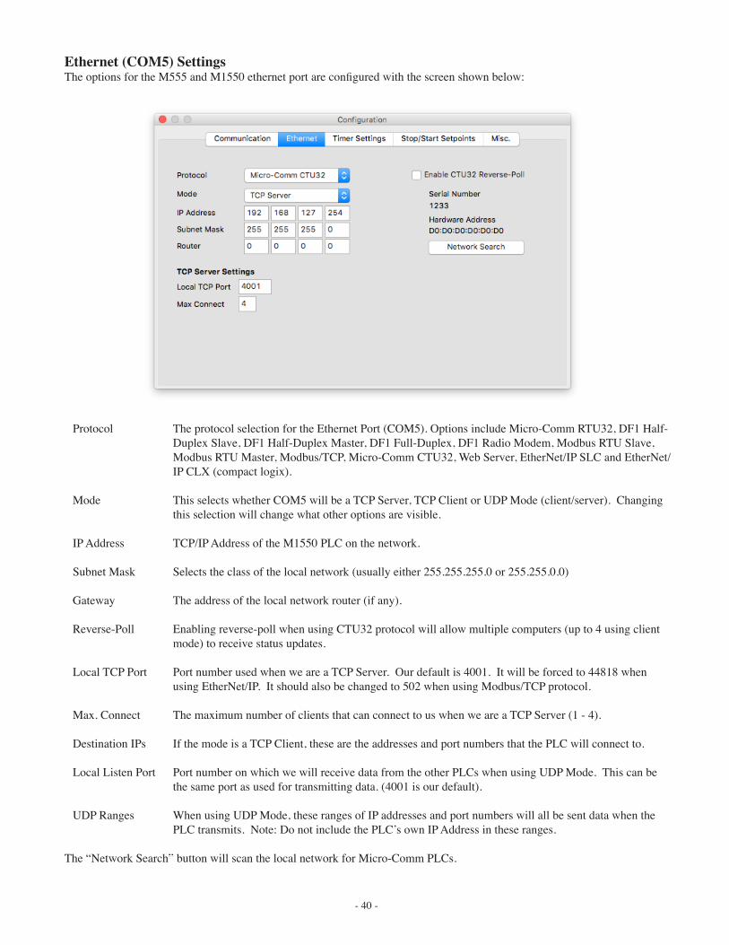
Ethernet (COM5) Settings The options for the M555 and M1550 ethernet port are configured with the screen shown below:
Protocol The protocol selection for the Ethernet Port (COM5). Options include Micro-Comm RTU32, DF1 Half-Duplex Slave, DF1 Half-Duplex Master, DF1 Full-Duplex, DF1 Radio Modem, Modbus RTU Slave, Modbus RTU Master, Modbus/TCP, Micro-Comm CTU32, Web Server, EtherNet/IP SLC and EtherNet/IP CLX (compact logix).
Mode This selects whether COM5 will be a TCP Server, TCP Client or UDP Mode (client/server). Changing
this selection will change what other options are visible.
IP Address TCP/IP Address of the M1550 PLC on the network.
Subnet Mask Selects the class of the local network (usually either 255.255.255.0 or 255.255.0.0)
Gateway The address of the local network router (if any).
Reverse-Poll Enabling reverse-poll when using CTU32 protocol will allow multiple computers (up to 4 using client mode) to receive status updates.
Local TCP Port Port number used when we are a TCP Server. Our default is 4001. It will be forced to 44818 when using EtherNet/IP. It should also be changed to 502 when using Modbus/TCP protocol.
Max. Connect The maximum number of clients that can connect to us when we are a TCP Server (1 - 4).
Destination IPs If the mode is a TCP Client, these are the addresses and port numbers that the PLC will connect to.
Local Listen Port Port number on which we will receive data from the other PLCs when using UDP Mode. This can be the same port as used for transmitting data. (4001 is our default).
UDP Ranges When using UDP Mode, these ranges of IP addresses and port numbers will all be sent data when the PLC transmits. Note: Do not include the PLC’s own IP Address in these ranges.
The “Network Search” button will scan the local network for Micro-Comm PLCs.
- 41 -
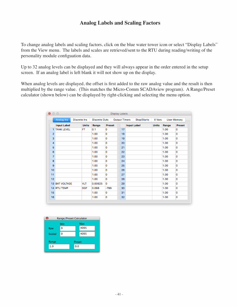
Analog Labels and Scaling Factors
To change analog labels and scaling factors, click on the blue water tower icon or select “Display Labels” from the View menu. The labels and scales are retrieved/sent to the RTU during reading/writing of the personality module configuation data.
Up to 32 analog levels can be displayed and they will always appear in the order entered in the setup screen. If an analog label is left blank it will not show up on the display.
When analog levels are displayed, the offset is first added to the raw analog value and the result is then multiplied by the range value. (This matches the Micro-Comm SCADAview program). A Range/Preset calculator (shown below) can be displayed by right-clicking and selecting the menu option.
- 42 -
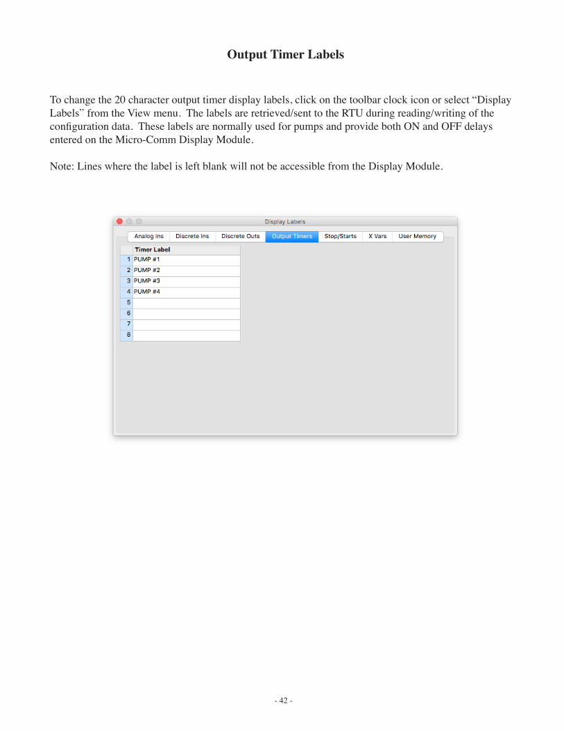
Output Timer Labels
To change the 20 character output timer display labels, click on the toolbar clock icon or select “Display Labels” from the View menu. The labels are retrieved/sent to the RTU during reading/writing of the configuration data. These labels are normally used for pumps and provide both ON and OFF delays entered on the Micro-Comm Display Module.
Note: Lines where the label is left blank will not be accessible from the Display Module.
- 43 -
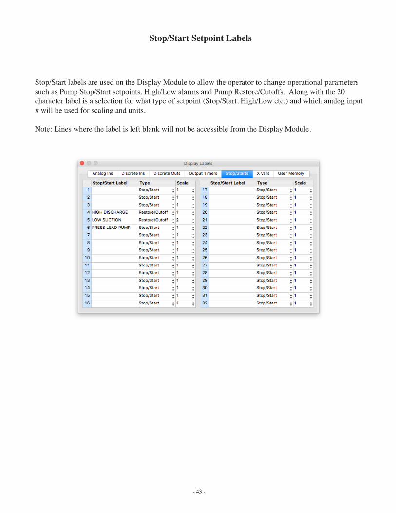
Stop/Start Setpoint Labels
Stop/Start labels are used on the Display Module to allow the operator to change operational parameters such as Pump Stop/Start setpoints, High/Low alarms and Pump Restore/Cutoffs. Along with the 20 character label is a selection for what type of setpoint (Stop/Start, High/Low etc.) and which analog input # will be used for scaling and units.
Note: Lines where the label is left blank will not be accessible from the Display Module.
- 44 -
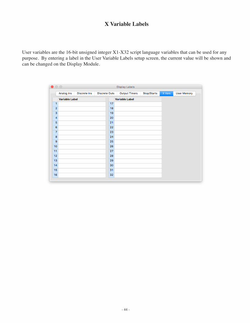
X Variable Labels
User variables are the 16-bit unsigned integer X1-X32 script language variables that can be used for any purpose. By entering a label in the User Variable Labels setup screen, the current value will be shown and can be changed on the Display Module.
- 45 -
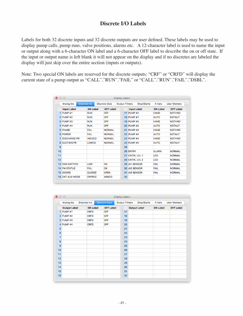
Discrete I/O Labels
Labels for both 32 discrete inputs and 32 discrete outputs are user defined. These labels may be used to display pump calls, pump runs, valve positions, alarms etc. A 12-character label is used to name the input or output along with a 6-character ON label and a 6-character OFF label to describe the on or off state. If the input or output name is left blank it will not appear on the display and if no discretes are labeled the display will just skip over the entire section (inputs or outputs).
Note: Two special ON labels are reserved for the discrete outputs: “CRF” or “CRFD” will display the current state of a pump output as “CALL”,”RUN”,”FAIL” or “CALL”,”RUN”,”FAIL”,”DSBL”.
- 46 -
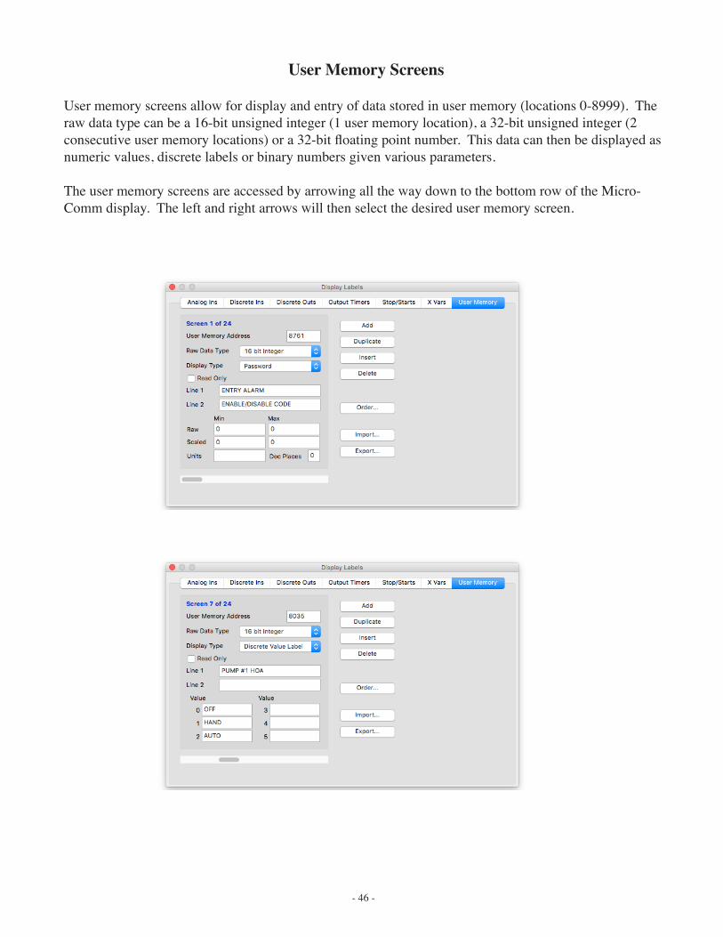
User Memory Screens
User memory screens allow for display and entry of data stored in user memory (locations 0-8999). The raw data type can be a 16-bit unsigned integer (1 user memory location), a 32-bit unsigned integer (2 consecutive user memory locations) or a 32-bit floating point number. This data can then be displayed as numeric values, discrete labels or binary numbers given various parameters.
The user memory screens are accessed by arrowing all the way down to the bottom row of the Micro-Comm display. The left and right arrows will then select the desired user memory screen.
- 47 -
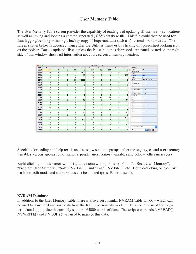
User Memory Table
The User Memory Table screen provides the capability of reading and updating all user memory locations as well as saving and loading a comma seperated (.CSV) database file. This file could then be used for data logging/trending or saving a backup copy of important data such as flow totals, runtimes etc. The screen shown below is accessed from either the Utilities menu or by clicking on spreadsheet looking icon on the toolbar. Data is updated “live” unless the Pause button is depressed. An panel located on the right side of this window shows all information about the selected memory location.
Special color coding and help text is used to show stations, groups, other message types and user memory variables. (green=groups, blue=stations, purple=user memory variables and yellow=other messages)
Right-clicking on this screen will bring up a menu with options to “Find...”, “Read User Memory”, “Program User Memory”, “Save CSV File...” and “Load CSV File...” etc. Double-clicking on a cell will put it into edit mode and a new values can be entered (press Enter to send).
NVRAM DatabaseIn addition to the User Memory Table, there is also a very similar NVRAM Table window which can be used to download and save data from the RTU’s personality module. This could be used for long-term data logging since it currently supports 65000 words of data. The script commands NVREAD(), NVWRITE() and NVCOPY() are used to manage this data.
- 48 -
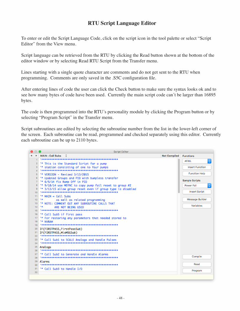
RTU Script Language Editor
To enter or edit the Script Language Code, click on the script icon in the tool palette or select “Script Editor” from the View menu.
Script language can be retrieved from the RTU by clicking the Read button shown at the bottom of the editor window or by selecting Read RTU Script from the Transfer menu.
Lines starting with a single quote character are comments and do not get sent to the RTU when programming. Comments are only saved in the .S5C configuration file.
After entering lines of code the user can click the Check button to make sure the syntax looks ok and to see how many bytes of code have been used. Currently the main script code can’t be larger than 16895 bytes.
The code is then programmed into the RTU’s personality module by clicking the Program button or by selecting “Program Script” in the Transfer menu.
Script subroutines are edited by selecting the subroutine number from the list in the lower-left corner of the screen. Each subroutine can be read, programmed and checked separately using this editor. Currently each subroutine can be up to 2110 bytes.
- 49 -
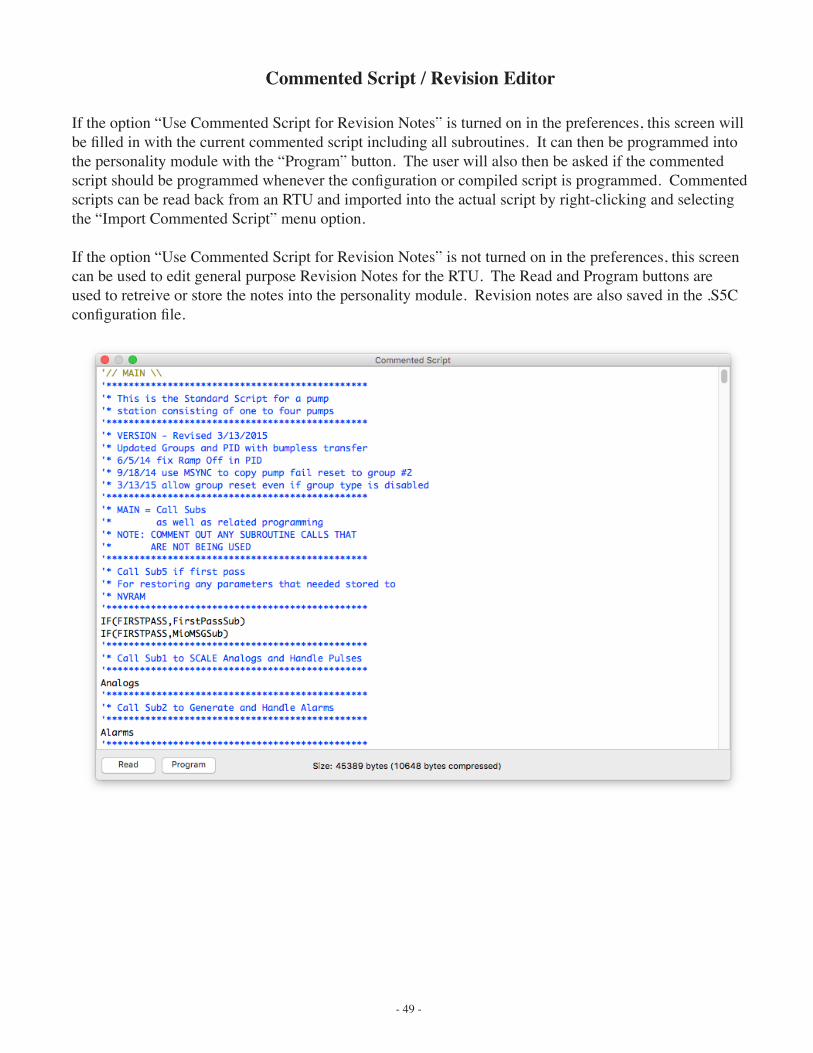
Commented Script / Revision Editor
If the option “Use Commented Script for Revision Notes” is turned on in the preferences, this screen will be filled in with the current commented script including all subroutines. It can then be programmed into the personality module with the “Program” button. The user will also then be asked if the commented script should be programmed whenever the configuration or compiled script is programmed. Commented scripts can be read back from an RTU and imported into the actual script by right-clicking and selecting the “Import Commented Script” menu option.
If the option “Use Commented Script for Revision Notes” is not turned on in the preferences, this screen can be used to edit general purpose Revision Notes for the RTU. The Read and Program buttons are used to retreive or store the notes into the personality module. Revision notes are also saved in the .S5C configuration file.
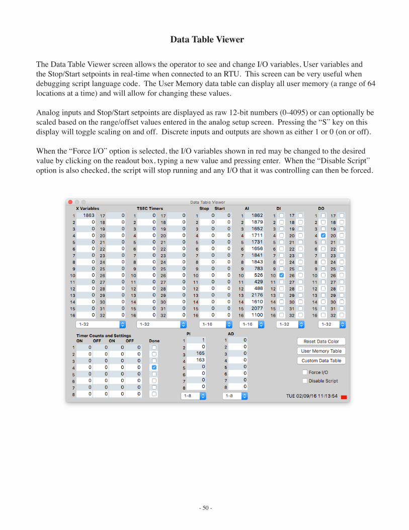
- 50 -
Data Table Viewer
The Data Table Viewer screen allows the operator to see and change I/O variables, User variables and the Stop/Start setpoints in real-time when connected to an RTU. This screen can be very useful when debugging script language code. The User Memory data table can display all user memory (a range of 64 locations at a time) and will allow for changing these values.
Analog inputs and Stop/Start setpoints are displayed as raw 12-bit numbers (0-4095) or can optionally be scaled based on the range/offset values entered in the analog setup screen. Pressing the “S” key on this display will toggle scaling on and off. Discrete inputs and outputs are shown as either 1 or 0 (on or off).
When the “Force I/O” option is selected, the I/O variables shown in red may be changed to the desired value by clicking on the readout box, typing a new value and pressing enter. When the “Disable Script” option is also checked, the script will stop running and any I/O that it was controlling can then be forced.
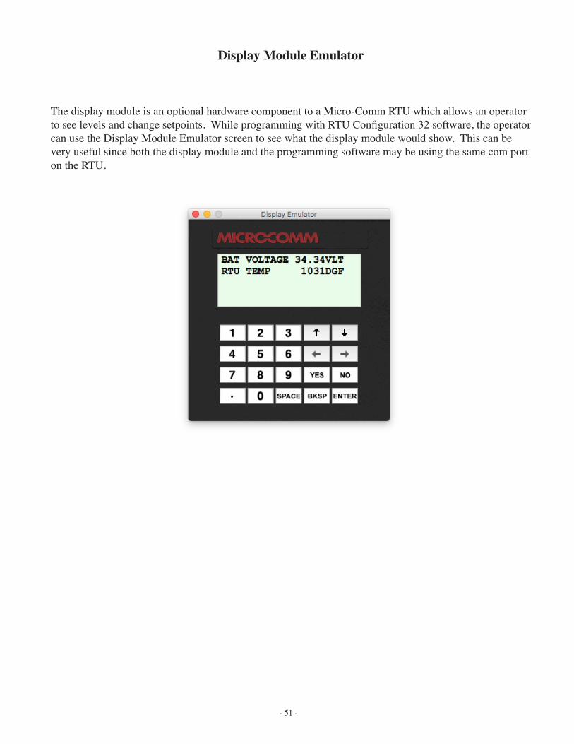
- 51 -
Display Module Emulator
The display module is an optional hardware component to a Micro-Comm RTU which allows an operator to see levels and change setpoints. While programming with RTU Configuration 32 software, the operator can use the Display Module Emulator screen to see what the display module would show. This can be very useful since both the display module and the programming software may be using the same com port on the RTU.
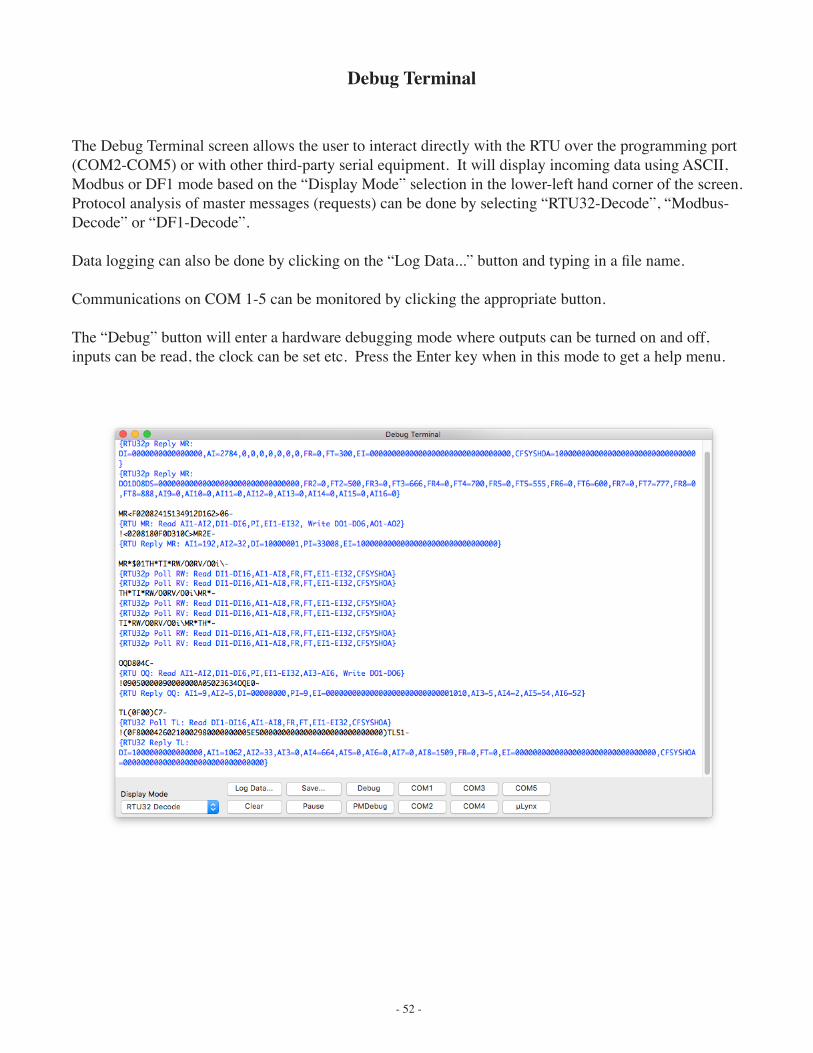
- 52 -
Debug Terminal
The Debug Terminal screen allows the user to interact directly with the RTU over the programming port (COM2-COM5) or with other third-party serial equipment. It will display incoming data using ASCII, Modbus or DF1 mode based on the “Display Mode” selection in the lower-left hand corner of the screen. Protocol analysis of master messages (requests) can be done by selecting “RTU32-Decode”, “Modbus-Decode” or “DF1-Decode”.
Data logging can also be done by clicking on the “Log Data...” button and typing in a file name.
Communications on COM 1-5 can be monitored by clicking the appropriate button.
The “Debug” button will enter a hardware debugging mode where outputs can be turned on and off, inputs can be read, the clock can be set etc. Press the Enter key when in this mode to get a help menu.


![2016 - -...2016/10/19 · 555 " 555555 Y555 X 555 ˘%ˆ > M555 ˘ / 555 Y555 M555 /ˆ 555 ˇ 5 ˝ 5 5˛˚ ] 5 ˇ5& 5 5 ˘%ˆ > M5 ˘ 5˛ % ˘ *( ˆ /ˆ .* ,55A 55ˆ % ˛55# L55˘](https://img.pdfslide.us/doc/110x75/6077983a019c9974231a3042/2016-20161019-555-555555-y555-x-555-m555-555.jpg)