Embed Size (px)
Citation preview
Micro-Cap 8 Analog/Digital Simulator
Taking simulation to a new level

Micro-Cap 8...
Eight Generation sof Refinement inCircuit Simulation
M icro-Cap 8 is an integrated schematic editor and mixed analog/digital simulatorthat provides an interactive sketch and simulate environment for electronics engineers.Since its original release in 1982, Micro-Cap has been steadily expanded and improved.Micro-Cap 8, the eighth generation, blends a modern, intuitive interface with robustnumerical algorithms to produce unparalleled levels of simulation power and ease ofuse. Nothing else comes close.
FasterAlgorithmic improvements, optimized code, and an integrated, seamless, analog/digital simulation interface contribute to the stunning speed of Micro-Cap 8.
More powerfulNumerous features contribute to Micro-Cap 8’s power. Among them are:• Multi-page hierarchical schematic editor• Supports most PSpiceTM, SPICE3, and many HSPICETM commands and models• IBIS model translator• Integral circuit optimizer• Integrated active and passive filter design function• PCB interface to popular packages• LAN version for collaborative projects• Native digital simulation engine• Device library with over 16,000 parts• Analog and digital behavioral modeling• Schematic waveform probing• Dynamic on-schematic voltage/state, current, power, and condition display• During the run plotting• Smith charts/polar plots• Powerful plotting and post-analysis functions• Multidimensional parameter stepping• 3D plotting• Performance functions and plots• Monte Carlo analysis• Optimizing parts modeler• BSIM 1.0, BSIM 2.0, BSIM3v3.2.4, and BSIM4.2.1 device models• EKV V2.6 MOSFET model• Animated seven segment displays, LEDs, switches, bars, meters, relays,
stoplights, and DC motors provide visualization and interaction.• Sample and hold, Timer, and Z transform devices• Lossy transmission lines• Jiles-Atherton nonlinear magnetics model• S-Y-Z-H-G parameter N-Port model for RF work• Dynamic AC and DC on-schematic displays for easy visualization
Easier to useThe graphical, user-friendly interface is simple to learn and use. Familiar SPICE models, plus extensions, are easy to apply. Over 500 warning and messages help you through problems, when the error occurs, not later in a text file.
Highly affordableYou can easily spend two to three times the cost of Micro-Cap 8 for other simulatorswithout matching its power, speed, and ease of use.
GuaranteedMicro-Cap 8 comes with a full, unconditional, 30 day money-back guarantee.

Principal Features
Integrated schematic editor and simulatorThe multi-page hierarchical schematic editor makes it easy tosketch a circuit. Once a circuit is created, you can do transient,AC, DC, transfer function, distortion, or sensitivity analysis.Editing the schematic and rerunning an analysis is easy. The editor features stepping, scaling, panning, multiple-object selection, rotation about three axes, mirroring, drag copying,
and clipboard functions, with multistage undoand redo. You can probe the schematic with themouse to display curves and waveforms, or useDynamic AC or DC to see voltage, current, andpower change as you edit the circuit.
SPICE compatible models and simulatorMicro-Cap 8 reads, writes, creates, and analyzes standard SPICE text files as well as its ownschematic files. You can use the schematic editorto create schematics or the text editor to buildSPICE text file circuits. Micro-Cap can analyzeeither format and can use text file subcircuitmodels in schematics. Micro-Cap also createsSPICE files from its own schematics.
Native digital simulatorThe internal 5-state, event-driven digital simulator lets you rundigital or mixed mode simulations using your own models orthose from our extensive digital library. The library includes over2000 standard digital parts from the following digital families:7400, AC, ACT, ALS, AS, F, H, HC, HCT, LS, LV, S (Schottky),CD4000 CMOS, ECL10K and ECL100K.
Active and passive filter designerThe active filter designer creates low pass,high pass, band pass, notch, and delay filterswith Bessel, Butterworth, Chebyshev, inverse-Chebyshev, or elliptic responses in both polynomial and schematic form. Individualstages can be chosen from many topologies,including Sallen-Key, MFB, Tow Thomas,Fleischer-Tow, KHN, and Acker-Mossberg.The passive filter designer creates low pass,high pass, band pass, and notch filters withButterworth or Chebyshev responses in several circuit configurations.
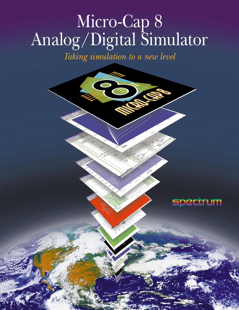
Optimizer–for fine tuning designsThe integral optimizer tunes parameters to maximize any performance function, or to fit any curve, handling manykinds of design optimization problems.
Parameter stepping–to see parameter dependenceStepping lets you explore design limits and tailor performance. You canstep component values, model parameters, and symbolic parameters.You can even step text to select different model names or subcircuits.
Performance Plots–for parameter sensitivityYou can directly measure and plot performancecharacteristics versus circuit parameters.Performance parameters include rise time,fall time, pulse width, frequency, period, peak,bandwidth, and many more.
Analysis
Design Optimization
Transient analysis–for plotting time-domain waveformsYou can plot digital state, voltage, current, power, energy, charge,
resistance, capacitance, inductance, B field, and H field. A variety of variables and mathematical functions simplify plots.
AC analysis–for investigating small signal behaviorWith AC analysis you can plot voltage or current and produce Bode plots, Nyquist diagrams, Nichols charts,Smith charts, polar plots, and noise. Real, imaginary,magnitude, phase, and group delay operators makeanalysis and plotting easy.
DC analysis–for plotting static DC variablesYou can use DC analysis for various plots, including transfer functions,where one source is varied, and device IV curves, where two sourcesare varied. Transfer function plots help to determine DC offset, bias,and overall amplifier DC gain.

Analog behavioral modeling–for system level simulationLaplace sources let you describe the S-plane lineartransfer function of a circuit block. Function sourceslet you model instantaneous nonlinear behavior.The source can be a mathematical function of anyother circuit variable, such as a node voltage or adevice current. Expressions can also be used for resistor, capacitor, and inductor values. Here are some sample expressions:
Digital behavioral modeling–for digital functionsPowerful digital behavioral primitives include logic expressions,pin delay blocks, and constraint checkers. These allow modelingof complex commercial parts like adders, multipliers, converters,and arithmetic logic units.
MODEL–for rapid creation of optimized device modelsIf you can’t find what you need in our huge library,you can use MODEL to produce optimized modelparameters from data sheet values or graphs.MODEL easily creates accurate models for diodes,bipolar transistors, MOSFETs, OPAMPs, nonlinearcores, and JFETs.
SPICE subcircuit models–for easy access to vendor modelsMicro-Cap 8 directly uses the SPICE subcircuit models provided by many semiconductor manufacturers for theirdevices, providing ready access to their modeling work.
Modeling
Monte Carlo–for design centering and yield optimizationMonte Carlo routines construct hundreds of circuits, each containing parts with parameters picked from distributions you choose. This helps identify circuit problems and improvesproduction yield. You can use both absolute and relative toler-ances and worst case, Gaussian, or uniform distributions.Results are generated in both numeric and histogram form for easy inspection and review.
G*b0/(s^2+b1*s+b0) Low pass filter -k*(v(p)-v(c)+u*(v(g)-v(c)))^1.5 TriodeVZ+tempco*(TEMP-28) Reference sourceSin(2*pi*T)*Exp(-T) Damped sine wave
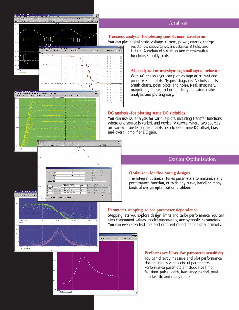
Nonlinear magnetics modelThe Jiles-Atherton magnetics model lets you model the nonlinearbehavior of cores, reactors, and transformers. Its state-variablemodel provides realistic hysteresis and saturation effects and accurately portrays remnance and coercivity. You can plot current,voltage, flux, and inductance. B and H fields can be plotted ineither CGS or SI units. The parts library includes models for hundreds of commercial devices.
IBIS translatorMany manufacturers now provide interface models in IBIS format, a kind of behavioral modeling language that describes the I/O pininterface in terms of impedance and timing.Micro-Cap 8 translates these IBIS models into useable SPICE models which accurately reproduce the calibration waveforms (GoldenWaveforms). The increased accuracy of the buffer models greatly simplifies board testing.
Advanced MOSFET modelsMicro-Cap 8 includes the EKV 2.6 and four BSIM models, BSIM1,BSIM2, BSIM3v3.2.4, and BSIM4.2.1 for advanced work with short channel devices. Short-distance matching and binning areprovided for advanced modeling.
Real time waveform plotting–for quick feedbackMicro-Cap 8 produces waveform plots andgraphs during the run, so you can stop the run to correct problems and avoid wasted time. It’salso much more interesting. You can change simulation parameters-like temperature, simula-tion time, or initial conditions–and start a newrun without re-compiling the circuit.
Direct schematic waveform probing–for fast measurementsand quick display of analysis resultsMicro-Cap 8 lets you probe schematics directly for waveforms.Simply point the mouse at a device or circuit node and click.You can set the probe to measure digital states, voltage, current,power, energy, charge, capacitance, flux, inductance, B field,or H field. The probe can display transient, AC, or DC analysisresults. It’s like probing a circuit with a scope, a spectrum analyzer, or a curve tracer.
Display and Plotting
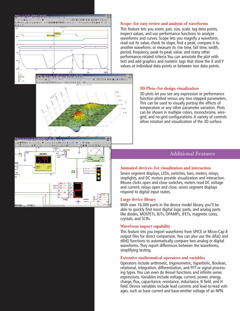
Scope–for easy review and analysis of waveformsThis feature lets you zoom, pan, size, scale, tag data points,inspect values, and use performance functions to analyze waveforms and curves. Scope lets you magnify a waveform,read out its value, check its slope, find a peak, compare it toanother waveform, or measure its rise time, fall time, width,period, frequency, peak-to-peak value, and many other performance-related criteria.You can annotate the plot with text and add graphics and numeric tags that show the X and Yvalues at individual data points or between two data points.
3D Plots–for design visualization3D plots let you see any expression or performancefunction plotted versus any two stepped parameters.This can be used to visually portray the effects oftemperature or any other parameter variation. Plotscan be shown in multiple colors, monochrome, wire-grid, and no-grid configurations. A variety of controlsallow rotation and visualization of the 3D surface.
Animated devices–for visualization and interactionSeven segment displays, LEDs, switches, bars, meters, relays,stoplights, and DC motors provide visualization and interaction.Mouse clicks open and close switches, meters read DC voltageand current, relays open and close, seven segment displaysrespond to digital input states.
Large device library With over 16,000 parts in the device model library, you’ll be able to quickly find most digital logic parts, and analog parts like diodes, MOSFETs, BJTs, OPAMPs, JFETs, magnetic cores,crystals, and SCRs.
Waveform import capabilityThis feature lets you import waveforms from SPICE or Micro-Cap 8output files for direct comparison. You can also use the difa() anddifd() functions to automatically compare two analog or digitalwaveforms. They report differences between the waveforms,simplifying testing.
Extensive mathematical operators and variablesOperators include arithmetic, trigonometric, hyperbolic, Boolean,relational, integration, differentiation, and FFT or signal process-ing types. You can even do Bessel functions and infinite seriesexpressions. Variables include voltage, current, power, energy,charge, flux, capacitance, resistance, inductance, B field, and Hfield. Device variables include lead currents and lead-to-lead volt-ages, such as base current and base-emitter voltage of an NPN.
Additional Features
Analog primitives• Battery voltage source• Voltage source (SPICE format)• Current source (SPICE format)• Pulse voltage source• Sine voltage source• User-defined file source• Resistor• Capacitor• Inductor• Diode• SPICE E, F, G, H sources• Linear dependent two port source• Transmission line (lossy or ideal)• Transformer• K device (magnetic coupling) • Bipolar junction transistor• MOSFET models
– Original levels 1, 2, and 3– BSIM1, BSIM2, BSIM3v3.2.4, BSIM4.2.1– EKV V2.6
• OPAMP• GaAsFET (3 models)• JFET• Analog behavioral sources
– Laplace function (S-domain expressions)– Laplace table (S-domain tabular functions)– Function (Time-domain algebraic expressions)– Table (Time-domain tabular functions)
• Z transform source• Sample and hold source• S-Y-Z-H-G parameter N-port model • Switches (3 models)• Timer function block• Macro blocks
– Absolute value– Amplifier– Center-tapped transformer– Clip function– Comparator– Crystal– Delay– DIAC– Differentiator– Digital potentiometer– Divider– F(s) Laplace block– Frequency shift keyer– Gyrator– Ideal transformer 2 port– Ideal transformer 3 port– Integrator– Multiplier– Noise source– Phase shift keyer– Potentiometer– Programmable unijunction transistor– Pulse width modulator– Relay– Resonant tank circuit– Schmitt trigger– Silicon-controlled rectifier– Slip circuit– Snubber diode– Spark gap– Subtractor– Summer (two input)– Summer (three input)– Triac– Triode– Voltage-controlled oscillator– Wideband transformer
Digital primitives• Standard and tri-state gates
– Buffer– Inverter– And– Or– Nand– Nor– Xor– Xnor
• Edge-triggered flip-flops– JK type– D type
• Gated flip-flops and latches– SR– D LATCH
• Digital loads– Pullup– Pulldown
• Delay line• Programmable logic array• Analog to digital converter• Digital to analog converter• Analog to digital interface• Digital to analog interface• Digital behavioral modeling
– Logic expression– Pin delay– Constraint checker
• Stimulus generators
Animated primitivesThese versatile devices use motion and color to indicate state behavior and respond to mouse clicks.
• Analog/digital voltmeter/ammeter• Analog color LED• Analog color bar• DC Motor• Digital LED• Digital switch• DPDT, DPST, SPST switches• Relay• Seven segment display• Traffic light
Help system
– Over 20,000 lines of on-line help is context sensitive, indexed, and topically arranged for easy learning.
– Over 500 error messages help you pinpoint circuit problems. Most error messages come with a "More"button for additional description of the nature of the problem.
– Over 125 sample circuits give you plenty of examples to learn design and simulation techniques.
– Over 100 Help Bar notes describe program features as you move the mouse over them.
– Over 15 live demos illustrate the workings of the program.
Spectrum Software
1021 South Wolfe RoadSunnyvale, CA 94086Tel: 408-738-4387 FAX: 408-738-4702 Internet: www.spectrum-soft.com Support: [email protected]: [email protected]
Device models