Embed Size (px)
Citation preview
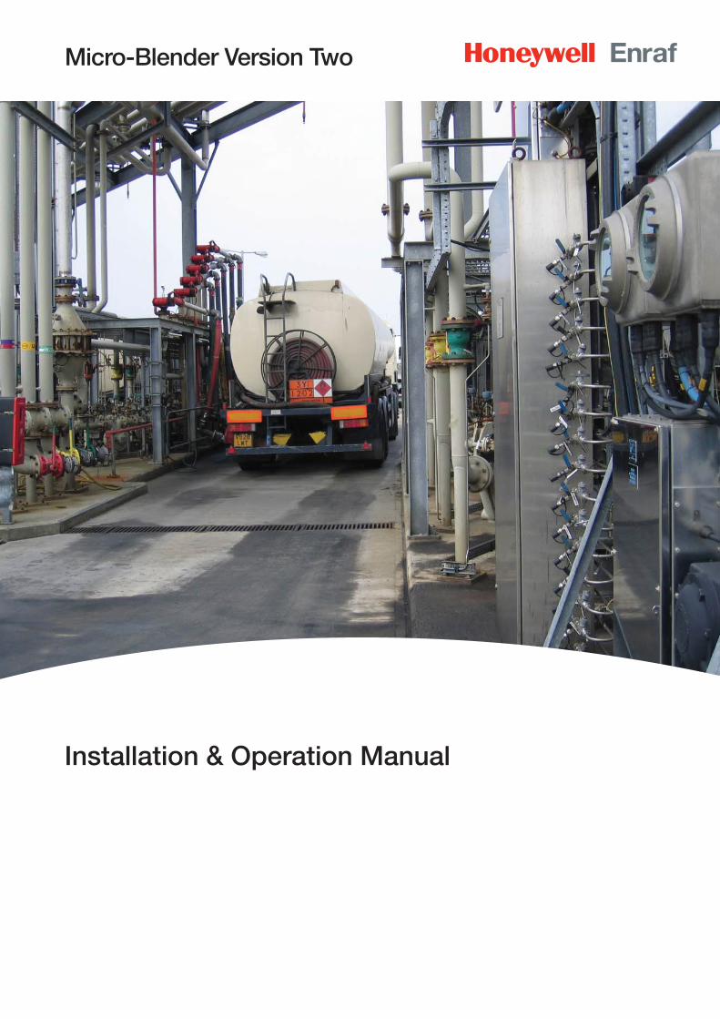
Micro-Blender Version Two
Installation & Operation Manual
Table Of Contents
CHAPTER 1 . . . . . . . . . . . . . . . . . . . . . . . . . . . . . . . . . . . . . . . . . . . . . . . . . . .1-1
1.1 Product Introduction . . . . . . . . . . . . . . . . . . . . . . . . . . . . . . . . . . . . . . . . . . . .1-1
1.2 Overview . . . . . . . . . . . . . . . . . . . . . . . . . . . . . . . . . . . . . . . . . . . . . . . . . . . . .1-2
1.3 Features . . . . . . . . . . . . . . . . . . . . . . . . . . . . . . . . . . . . . . . . . . . . . . . . . . . . . .1-2
CHAPTER 2 . . . . . . . . . . . . . . . . . . . . . . . . . . . . . . . . . . . . . . . . . . . . . . . . . . .2-1
2.1 Controller Inputs . . . . . . . . . . . . . . . . . . . . . . . . . . . . . . . . . . . . . . . . . . . . . . .2-1
2.1.1 Permissive . . . . . . . . . . . . . . . . . . . . . . . . . . . . . . . . . . . . . . . . . . . . . . . . . . . . .2-1
2.1.2 Alarm Reset . . . . . . . . . . . . . . . . . . . . . . . . . . . . . . . . . . . . . . . . . . . . . . . . . . . .2-1
2.1.3 Wild Stream Input Pulses . . . . . . . . . . . . . . . . . . . . . . . . . . . . . . . . . . . . . . . . . .2-1
2.1.4 Blend Stream Meter Input . . . . . . . . . . . . . . . . . . . . . . . . . . . . . . . . . . . . . . . . .2-1
2.2 Controller Outputs . . . . . . . . . . . . . . . . . . . . . . . . . . . . . . . . . . . . . . . . . . . . . .2-1
2.2.1 Blend Stream Valve Control . . . . . . . . . . . . . . . . . . . . . . . . . . . . . . . . . . . . . . . .2-1
2.2.2 AC Alarm Output . . . . . . . . . . . . . . . . . . . . . . . . . . . . . . . . . . . . . . . . . . . . . . . .2-2
2.2.3 Factored Pulse Output. . . . . . . . . . . . . . . . . . . . . . . . . . . . . . . . . . . . . . . . . . . .2-2
2.3 Display Screens . . . . . . . . . . . . . . . . . . . . . . . . . . . . . . . . . . . . . . . . . . . . . . . .2-2
2.3.1 Display . . . . . . . . . . . . . . . . . . . . . . . . . . . . . . . . . . . . . . . . . . . . . . . . . . . . . . .2-2
2.3.2 Adjustment . . . . . . . . . . . . . . . . . . . . . . . . . . . . . . . . . . . . . . . . . . . . . . . . . . . .2-2
2.3.3 Start up Screens . . . . . . . . . . . . . . . . . . . . . . . . . . . . . . . . . . . . . . . . . . . . . . . .2-3
2.3.4 Running Screens . . . . . . . . . . . . . . . . . . . . . . . . . . . . . . . . . . . . . . . . . . . . . . . .2-3
2.3.5 Deviation Screen . . . . . . . . . . . . . . . . . . . . . . . . . . . . . . . . . . . . . . . . . . . . . . . .2-4
2.3.6 Permitted Deviation Screen . . . . . . . . . . . . . . . . . . . . . . . . . . . . . . . . . . . . . . . .2-4
2.3.7 Make Up Deviation Screen . . . . . . . . . . . . . . . . . . . . . . . . . . . . . . . . . . . . . . . .2-4
2.3.8 Accumulated Total Screen . . . . . . . . . . . . . . . . . . . . . . . . . . . . . . . . . . . . . . . . .2-5
2.3.9 Transaction Total Screen . . . . . . . . . . . . . . . . . . . . . . . . . . . . . . . . . . . . . . . . . .2-5
2.3.10 Manual Display of Running Screens . . . . . . . . . . . . . . . . . . . . . . . . . . . . . . . . . .2-5
CHAPTER 3 . . . . . . . . . . . . . . . . . . . . . . . . . . . . . . . . . . . . . . . . . . . . . . . . . . .3-1
3.1 Changing Parameter Values using the Hand-Held Controller . . . . . . . . . . . .3-1
3.2 The Hand-Held Controller . . . . . . . . . . . . . . . . . . . . . . . . . . . . . . . . . . . . . . . .3-2
3.3 Accessing Parameter Values using the Hand-Held Controller . . . . . . . . . . .3-3
CHAPTER 4 . . . . . . . . . . . . . . . . . . . . . . . . . . . . . . . . . . . . . . . . . . . . . . . . . . .4-1
4.1 Parameter Table . . . . . . . . . . . . . . . . . . . . . . . . . . . . . . . . . . . . . . . . . . . . . . .4-1
4.1.1 Main Parameter Table . . . . . . . . . . . . . . . . . . . . . . . . . . . . . . . . . . . . . . . . . . . .4-1
4.1.2 Alarm Parameter Table . . . . . . . . . . . . . . . . . . . . . . . . . . . . . . . . . . . . . . . . . . .4-3
ii Micro Blender V2 Part No.: 4418203 - Revision 0 Installation & Operation Manual
Part No.: 4418203 - Revision 0 Micro Blender V2 iii Installation & Operation Manual
4.1.3 Password Security Parameter Table . . . . . . . . . . . . . . . . . . . . . . . . . . . . . . . . .4-3
4.1.4 Read Only Parameter Table . . . . . . . . . . . . . . . . . . . . . . . . . . . . . . . . . . . . . . . .4-4
4.2 Micro-Blender V2 Controller Main Parameter Details . . . . . . . . . . . . . . . . . .4-4
4.3 Micro-Blender V2 Controller Calibration Mode Parameter Details . . . . . . .4-14
CHAPTER 5 . . . . . . . . . . . . . . . . . . . . . . . . . . . . . . . . . . . . . . . . . . . . . . . . . . .5-1
5.1 Micro-Blender V2 Controller Alarm Parameter Details . . . . . . . . . . . . . . . . .5-1
5.2 Micro-Blender V2 Controller Security Parameters . . . . . . . . . . . . . . . . . . . .5-4
5.3 Micro-Blender V2 Controller Read - Only Parameters . . . . . . . . . . . . . . . . .5-6
CHAPTER 6 . . . . . . . . . . . . . . . . . . . . . . . . . . . . . . . . . . . . . . . . . . . . . . . . . . .6-1
6.1 Micro-Blender V2 Controller Task Codes . . . . . . . . . . . . . . . . . . . . . . . . . . . .6-1
6.2 Micro-Blender V2 Controller Control Description . . . . . . . . . . . . . . . . . . . . .6-1
6.2.1 Control Method . . . . . . . . . . . . . . . . . . . . . . . . . . . . . . . . . . . . . . . . . . . . . . . . .6-3
6.2.2 Control Adjustment . . . . . . . . . . . . . . . . . . . . . . . . . . . . . . . . . . . . . . . . . . . . . .6-6
6.3 Calibrating the Micro-Blender V2 . . . . . . . . . . . . . . . . . . . . . . . . . . . . . . . . . .6-8
6.3.1 Procedure . . . . . . . . . . . . . . . . . . . . . . . . . . . . . . . . . . . . . . . . . . . . . . . . . . . . .6-8
6.3.2 K-Factors: . . . . . . . . . . . . . . . . . . . . . . . . . . . . . . . . . . . . . . . . . . . . . . . . . . . . .6-9
6.3.3 Test Calibration Procedure: . . . . . . . . . . . . . . . . . . . . . . . . . . . . . . . . . . . . . . . .6-9
6.3.4 Set-Up and Calibration: . . . . . . . . . . . . . . . . . . . . . . . . . . . . . . . . . . . . . . . . . .6-10
CHAPTER 7 . . . . . . . . . . . . . . . . . . . . . . . . . . . . . . . . . . . . . . . . . . . . . . . . . . .7-1
7.1 Micro-Blender V2 Controller Display Setup . . . . . . . . . . . . . . . . . . . . . . . . . .7-1
7.1.1 Idle Mode Display Information . . . . . . . . . . . . . . . . . . . . . . . . . . . . . . . . . . . . . .7-1
7.1.2 Time & Temperature Confi rmation . . . . . . . . . . . . . . . . . . . . . . . . . . . . . . . . . . .7-1
7.1.3 Analog Valve Control Output Display . . . . . . . . . . . . . . . . . . . . . . . . . . . . . . . . .7-1
7.2 Temperature Compensation . . . . . . . . . . . . . . . . . . . . . . . . . . . . . . . . . . . . . .7-2
7.2.1 Background . . . . . . . . . . . . . . . . . . . . . . . . . . . . . . . . . . . . . . . . . . . . . . . . . . .7-2
7.2.2 Temperature Transmitter Use . . . . . . . . . . . . . . . . . . . . . . . . . . . . . . . . . . . . . . .7-2
7.2.3 Temperature Compensation Calculations . . . . . . . . . . . . . . . . . . . . . . . . . . . . . .7-2
7.3 Clean Start Operation . . . . . . . . . . . . . . . . . . . . . . . . . . . . . . . . . . . . . . . . . . .7-4
7.3.1 SETUP: . . . . . . . . . . . . . . . . . . . . . . . . . . . . . . . . . . . . . . . . . . . . . . . . . . . . . . .7-4
7.3.2 USE: . . . . . . . . . . . . . . . . . . . . . . . . . . . . . . . . . . . . . . . . . . . . . . . . . . . . . . . . .7-5
CHAPTER 8 . . . . . . . . . . . . . . . . . . . . . . . . . . . . . . . . . . . . . . . . . . . . . . . . . . .8-1
8.1 Micro-Blender V2 Controller Communication Settings . . . . . . . . . . . . . . . . .8-1
8.1.1 Communications and Communication Wiring . . . . . . . . . . . . . . . . . . . . . . . . . .8-2
8.2 Accessing Micro-Blender V2 Parameters via Communications . . . . . . . . . .8-3
Table Of Contents
iv Micro Blender V2 Part No.: 4418203 - Revision 0 Installation & Operation Manual
8.3 Retrieving Archived Transaction Records . . . . . . . . . . . . . . . . . . . . . . . . . . .8-4
8.3.1 Automated Retrieval Process . . . . . . . . . . . . . . . . . . . . . . . . . . . . . . . . . . . . . . .8-4
8.3.2 Bulk Retrieval Process . . . . . . . . . . . . . . . . . . . . . . . . . . . . . . . . . . . . . . . . . . . .8-5
8.3.3 Transaction Record Format . . . . . . . . . . . . . . . . . . . . . . . . . . . . . . . . . . . . . . . .8-5
CHAPTER 9 . . . . . . . . . . . . . . . . . . . . . . . . . . . . . . . . . . . . . . . . . . . . . . . . . . .9-1
9.1 Micro-Blender V2 Controller Parameter Format & Access Table . . . . . . . . .9-1
9.2 Micro-Blender V2 Controller Communications Reported Alarm Code Table . . . . . . . . . . . . . . . . . . . . . . . . . . . . . . . . . . . . . . . . . . . . . .9-5
CHAPTER 10 . . . . . . . . . . . . . . . . . . . . . . . . . . . . . . . . . . . . . . . . . . . . . . . . .10-1
10.1 Wiring Considerations . . . . . . . . . . . . . . . . . . . . . . . . . . . . . . . . . . . . . . . . . .10-1
10.2 Micro-Blender V2 Face Plate Lamp Identifi cation . . . . . . . . . . . . . . . . . . . .10-2
10.3 Micro-Blender V2 RS-485 Communications 2-Wire — 4-Wire Jumper Location . . . . . . . . . . . . . . . . . . . . . . . . . . . . . . . .10-3
10.4 Micro-Blender V2 Base Plate . . . . . . . . . . . . . . . . . . . . . . . . . . . . . . . . . . . .10-4
10.5 Micro-Blender V2 Controller Wiring Termination Table . . . . . . . . . . . . . . . .10-5
10.6 Micro-Blender V2 Controller Dimensions . . . . . . . . . . . . . . . . . . . . . . . . . . .10-6
10.7 Micro-Blender V2 Typical Wiring Connection Drawings . . . . . . . . . . . . . . .10-7
10.8 Micro-Blender V2 Typical Wiring Connection Drawings . . . . . . . . . . . . . .10-10
CHAPTER 11 . . . . . . . . . . . . . . . . . . . . . . . . . . . . . . . . . . . . . . . . . . . . . . . . .11-1
11.1 Micro-Blender V2 Specifi cations . . . . . . . . . . . . . . . . . . . . . . . . . . . . . . . . .11-1
CHAPTER 12 . . . . . . . . . . . . . . . . . . . . . . . . . . . . . . . . . . . . . . . . . . . . . . . . .12-1
12.1 Micro-Blender V2 Parts Identifi cation . . . . . . . . . . . . . . . . . . . . . . . . . . . . .12-1
Table Of Contents
Part No.: 4418203 - Revision 0 Micro Blender V2 1-1 Installation & Operation Manual
CHAPTER 1
1.1 Product Introduction
Welcome to the Micro-Blender V2, one of the Honeywell Enraf line of blend controllers. The design of the Micro-Blender V2 was based on Honeywell Enraf 20 year involvement with blending systems.
The Micro-Blender V2 utilizes two product streams; the monitored stream is referred to as the Wild Stream, and the controlled stream is referred to as the Blend Stream. The Micro-Blender V2 Controller is designed to be cost effective and simple to operate, yet provide blend control accuracy previously only found in expensive (and complicated) systems.
The Micro-Blender V2 makes it easy for you to control all the operating parameters of your blending process, using either the Hand-Held infrared controller or serial communications with our Type I, Type II, Type IV or Type V protocols.
In order to best acquaint yourself with the operation of the Micro-Blender V2, we suggest that you thoroughly review this manual before beginning operation of your blending system.
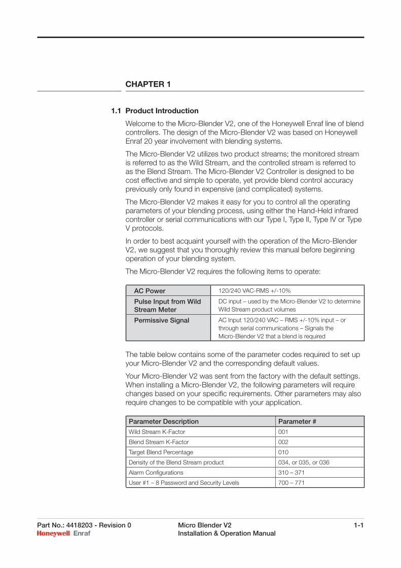
The Micro-Blender V2 requires the following items to operate:
The table below contains some of the parameter codes required to set up your Micro-Blender V2 and the corresponding default values.
Your Micro-Blender V2 was sent from the factory with the default settings. When installing a Micro-Blender V2, the following parameters will require changes based on your specifi c requirements. Other parameters may also require changes to be compatible with your application.
AC Power 120/240 VAC-RMS +/-10%
Pulse Input from Wild Stream Meter
DC input – used by the Micro-Blender V2 to determine Wild Stream product volumes
Permissive Signal AC Input 120/240 VAC – RMS +/-10% input – or through serial communications – Signals the Micro-Blender V2 that a blend is required
Parameter Description Parameter #
Wild Stream K-Factor 001
Blend Stream K-Factor 002
Target Blend Percentage 010
Density of the Blend Stream product 034, or 035, or 036
Alarm Confi gurations 310 – 371
User #1 – 8 Password and Security Levels 700 – 771
1-2 Micro Blender V2 Part No.: 4418203 - Revision 0 Installation & Operation Manual
1.2 Overview
Industry-leading Honeywell Enraf has always been a pioneer in the fi eld of fuel blending systems. Since its founding in 1955, the company has expanded its scope of expertise to the point where it occupies a 52,000 square foot manufacturing facility with over 45 engineers, technicians and support staff. Honeywell Enraf commitment to continued development is emphasized by our expanded Research and Development Department, which now incorporates microprocessor based electronics design and manufacturing capabilities. Honeywell Enraf lives by the axiom, “Accuracy You Can Count On.”
The Micro-Blender V2 is an intelligent blend controller which makes use of the latest advancements in microprocessor technology to bring unparalleled accuracy to blending applications. The Micro-Blender V2 uses the Dallas 80C320 microprocessor. For unparalleled speed and performance the Micro-Blender V2 is programmed using C, and then compiled for optimum performance. Operating code for the Micro-Blender V2 is stored in an EPROM (Erasable Programmable Read Only Memory) chip.
All of the more than 40 user defi nable operational parameters of the Micro-Blender V2 can be programmed using the Hand-Held Controller. This provides easy setup during the initial installation.
For security the Micro-Blender V2 provides 4 security levels and authorization for 8 users, with critical parameters accessible only with the highest security level.
Blend percentages can be adjusted in the Micro-Blender V2 “on the fl y”. This allows external sensors to determine product composition and make adjustments to the blending operation through serial communications. This feature becomes extremely useful if your application involves blending to specifi c process setpoints.
1.3 Features
The following is a list of Micro-Blender V2 features which will be examined in greater detail in the sections that follow:
Dallas 80C320 8-bit microprocessor
Blend Stream product pulse output
Wild Stream and Blend Stream Product totals stored internally
Selectable gross or net (gst) blending
Selectable upstream or downstream blend point confi guration
User-defi nable alarm conditions (off, on)
User-defi nable high and low alarm limit function
4 supported communications protocols
Chapter 1
Part No.: 4418203 - Revision 0 Micro Blender V2 1-3 Installation & Operation Manual
Infrared Hand-Held Controller
EIA 485 (2-wire) communications at 1200/2400/9600/19,200 baud
DC factored pulse input capability
Backlit LCD (Liquid Crystal Display) with 2 lines by 14 characters
Internal watchdog low power protection
4 levels of password security (8 users defi nable)
Chapter 1

1-4 Micro Blender V2 Part No.: 4418203 - Revision 0 Installation & Operation Manual
Chapter 1
Intentionally left blank.
Part No.: 4418203 - Revision 0 Micro Blender V2 2-1 Installation & Operation Manual
CHAPTER 2
2.1 Controller Inputs
2.1.1 PERMISSIVEThe permissive signal input to the Micro-Blender V2 Controller can be utilized to “permit” the unit to blend. This input is a status input, meaning it is “ON” continuously allowing the blender to operate. Application of this status signal causes the blender to clear the previous transaction total and begin a new transaction or batch. Three AC permissive inputs are provided and allow blending at any one of the three rates contained in Parameter # 010, 011, or 012. The permissive command may be communicated via the RS-485 interface also.
2.1.2 ALARM RESETAn AC or a DC momentary pulse on the RESET input will clear an existing alarm condition. Alarms may also be cleared using the RS-485 communications interface, or via the hand-held infrared controller.
2.1.3 WILD STREAM INPUT PULSESThe Honeywell Enraf family of blenders utilizes product fl ow rate signals that are pulse signal based. Pulses are DC with multiple pulses per unit volume product signaling. This signal accumulates product volume in the blender electronic controller and causes it to ratio in the blend product at the customer’s recipe requirements.
2.1.4 BLEND STREAM METER INPUTThis high speed pulse input is capable of capturing pulses up to 5khz in frequency and is dedicated to the accumulation of pulses from the blend stream fl ow meter.
2.2 Controller Outputs
2.2.1 BLEND STREAM VALVE CONTROLThe Micro-Blender V2 Controller controls the blend stream fl ow rate by changing the position of the blend stream control valve. The blender uses digital valve control technology common to the fuel loading industry. This technique utilizes two solenoid valves to modulate the position of the blend stream control valve. More details on the operation of these valves is provided in the Operations section of this manual.
The Micro-Blender V2 Controller provides a separate AC power input for the solenoids and alarm triac. This input can be supplied by an emergency shutdown interrupted source, thus granting override control external to the blender controller.
2-2 Micro Blender V2 Part No.: 4418203 - Revision 0 Installation & Operation Manual
2.2.2 AC ALARM OUTPUTThe Micro-Blender V2 Controller has two AC triac output available for alarm annunciation. These optically isolated, high current triacs are provided power from the AC feed connection. The feed input can be simply jumpered to the power feeding the Micro-Blender V2 Controller or provided with an isolated source of power from a different supply, thus maintaining complete isolation. The Alarm Output can be user confi gured as either a Fail Safe alarm output or as a Non-Fail Safe alarm output. See Parameter 300 for this setting selection.
2.2.3 FACTORED PULSE OUTPUTThe Micro-Blender V2 Controller has one DC factored pulse output. This optically isolated, high current power transistor output has both the emitter and collector connections available, allowing either pull-up or pull-down wiring options. The output may be utilized in the following ways: One pulse output for each whole unit volume of blend stream volume
dispensed. Ten pulses out for each whole unit volume of blend stream volume
dispensed. 100 pulses out for each whole unit volume of blend stream volume
dispensed. 1000 pulses out for each whole unit volume of blend stream volume
dispensed.
2.3 Display Screens
The Micro-Blender V2 electronics module displays several different text messages during operation. This section of the manual describes these screens in detail.
2.3.1 DisplayThe Micro-Blender V2 electronics module display consists of two lines containing sixteen characters in each line. The total characters that can be displayed in single screen are thirty-two.
2.3.2 AdjustmentThe display uses liquid crystal technology. At certain viewing angles, the characters can appear to fade out or turn into a dark rectangle. After the panel and electronics enclosure are mounted in the operation location, the display angle can be adjusted to provide the clearest display of text to the user.
CAUTION: The following procedure requires opening the electronics enclosure. DO NOT OPEN THE ENCLOSURE IN THE PRESENCE OF HAZARDOUS VAPORS. Follow all applicable company policies and regulations regarding service of electrical equipment in hazardous areas before proceeding.
Chapter 2
Part No.: 4418203 - Revision 0 Micro Blender V2 2-3 Installation & Operation Manual
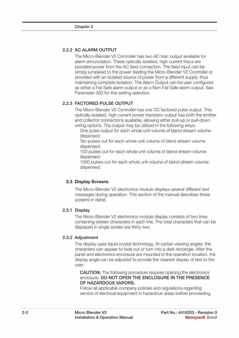
The adjustment of the display is a micro-potentiometer control located on the round circuit board immediately behind the display circuit board. The control is accessible from the front of the module while installed and powered on. Refer to the drawing below for the location of the control. Use a small straight blade screwdriver to rotate the control until the best viewing of characters is achieved.
2.3.3 Start up ScreensUpon applying power to the electronics there are sequences of three screens that are displayed to the user. The initial screen is a message that the module is testing its memory prior to loading the program.
Testing Memory Please Wait...
After a few seconds, the screen above is replaced by the next screen in the sequence. It is the device identifi er screen and also displays the major mode of the blender, upstream or downstream. Refer to the description of parameter number 080 to determine which mode is correct for your application.
Dev. = NET_MB Mode = Upstream
The fi nal screen in the start up sequence is the running screen or screens. Those screens are described next.
2.3.4 Running ScreensThe user has the ability to determine which screen or screens are displayed during normal operation. There are three run mode screens
Chapter 2
2-4 Micro Blender V2 Part No.: 4418203 - Revision 0 Installation & Operation Manual
available. They are the Deviation Screen, the Accumulated Total screen, and the Transaction Screen. Each of these is described below. The user selects which screen or screens are displayed by entering a value in parameter 152. Refer to the section on parameter settings to select which screens are displayed. The factory default setting for the running screen is the deviation screen.
If more than one screen is selected for display, the screens alternate for viewing. The time period that each screen remains in place is determined by the value in parameter 151.
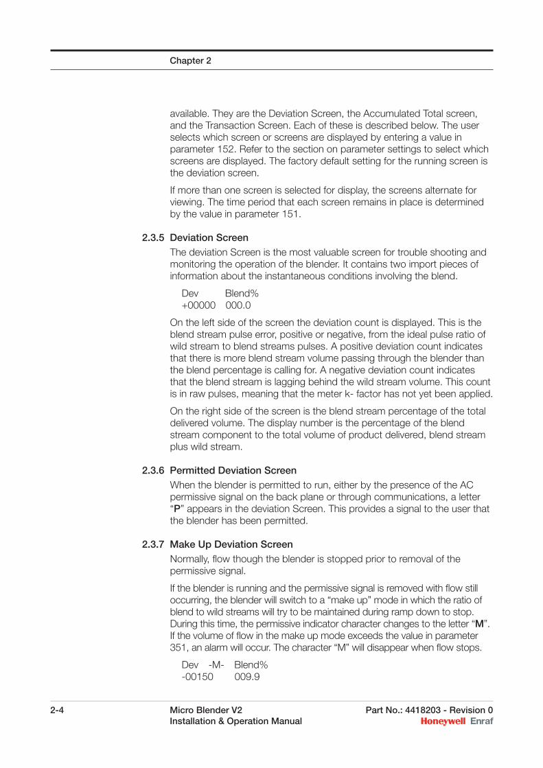
2.3.5 Deviation ScreenThe deviation Screen is the most valuable screen for trouble shooting and monitoring the operation of the blender. It contains two import pieces of information about the instantaneous conditions involving the blend.
Dev Blend% +00000 000.0
On the left side of the screen the deviation count is displayed. This is the blend stream pulse error, positive or negative, from the ideal pulse ratio of wild stream to blend streams pulses. A positive deviation count indicates that there is more blend stream volume passing through the blender than the blend percentage is calling for. A negative deviation count indicates that the blend stream is lagging behind the wild stream volume. This count is in raw pulses, meaning that the meter k- factor has not yet been applied.
On the right side of the screen is the blend stream percentage of the total delivered volume. The display number is the percentage of the blend stream component to the total volume of product delivered, blend stream plus wild stream.
2.3.6 Permitted Deviation ScreenWhen the blender is permitted to run, either by the presence of the AC permissive signal on the back plane or through communications, a letter “P” appears in the deviation Screen. This provides a signal to the user that the blender has been permitted.
2.3.7 Make Up Deviation ScreenNormally, fl ow though the blender is stopped prior to removal of the permissive signal.
If the blender is running and the permissive signal is removed with fl ow still occurring, the blender will switch to a “make up” mode in which the ratio of blend to wild streams will try to be maintained during ramp down to stop. During this time, the permissive indicator character changes to the letter “M”. If the volume of fl ow in the make up mode exceeds the value in parameter 351, an alarm will occur. The character “M” will disappear when fl ow stops.
Dev -M- Blend% -00150 009.9
Chapter 2
Part No.: 4418203 - Revision 0 Micro Blender V2 2-5 Installation & Operation Manual
2.3.8 Accumulated Total ScreenThe Accumulated Total Screen is the grand total of each individual component volume that has passed through the blender since start-up or since the blender totals were last cleared. The “W” designates the wild stream volume and the “B” indicates the blend stream volume. The totals are in whole units, with those units being determined by the k-factors used. To clear these totals use Task 800, 801, or 802 respectively.
W(A)- 00000000 B(A)- 00000000
2.3.9 Transaction Total ScreenThe transaction Total Screen is similar to the Accumulated Total Screen. The fi rst line of the displayed volume is for the wild stream volume and the second is for the blend stream component volume.
W(T)- 00000000 B(T)- 00000000
This time however, the totals represent the volume of product that has fl owed during this permissive cycle. When the permissive signal is applied to the AC permissive input on the back plane or the blender is sent a Task 010 via communications, these totals clear to zero. They accumulate as the blender runs and maintain their value until permissive is removed and reapplied.
Note: There is greater resolution available in the transaction totals with the display set to hundredths of unit volumes.
2.3.10 Manual Display of Running ScreensIn addition to the use of parameter 152 to permanently select which screen or screens are going to be displayed, the user can temporarily call up any one of the three running mode screens regardless of which ones are being normally displayed. Using the infrared hand-held remote control, the user can press the ATT key to get the controller’s attention, and then press F1, F2, or F3 buttons. Each button selects a different screen. When the period in parameter 151 expires, the display returns to the screen display selected in parameter 152.
Chapter 2

2-6 Micro Blender V2 Part No.: 4418203 - Revision 0 Installation & Operation Manual
Chapter 2
Intentionally left blank.
Part No.: 4418203 - Revision 0 Micro Blender V2 3-1 Installation & Operation Manual
CHAPTER 3
3.1 Changing Parameter Values using the Hand-Held Controller
The Hand-Held Controller (HHC) uses infrared signals to transmit ASCII characters to the Micro-Blender V2 controller. This unique use of infrared technology allows the operator to make adjustments in programming without removing the cover of the explosion-proof enclosure on-site. All prompts which require an operator response are clearly indicated on the Micro-Blender V2 controller LCD (Liquid Crystal Display).
The infrared receiver on the Micro-Blender V2 controller is designed to be insensitive to interference from light sources other than the HHC.
The HHC-4 Hand-Held Controller stores all of the infrared commands permanently in the 87C51 micro-controller. With the infrared codes stored in the micro-controller the HHC-4 can go without battery power indefi nitely, and be restored to full operation by inserting a fresh set of batteries.
A “sleep” mode was designed into the HHC-4 to reduce battery consumption. When the HHC-4 is fi rst used, or after a period of inactivity of approximately 30 seconds, the ATTN key must be pressed to “wake-up” the HHC-4. The SEND light will blink, indicating that the HHC-4 is ready for operation.
The HHC-4 has been DEMKO approved for use in hazardous atmospheres, Class 1, Group C & D.
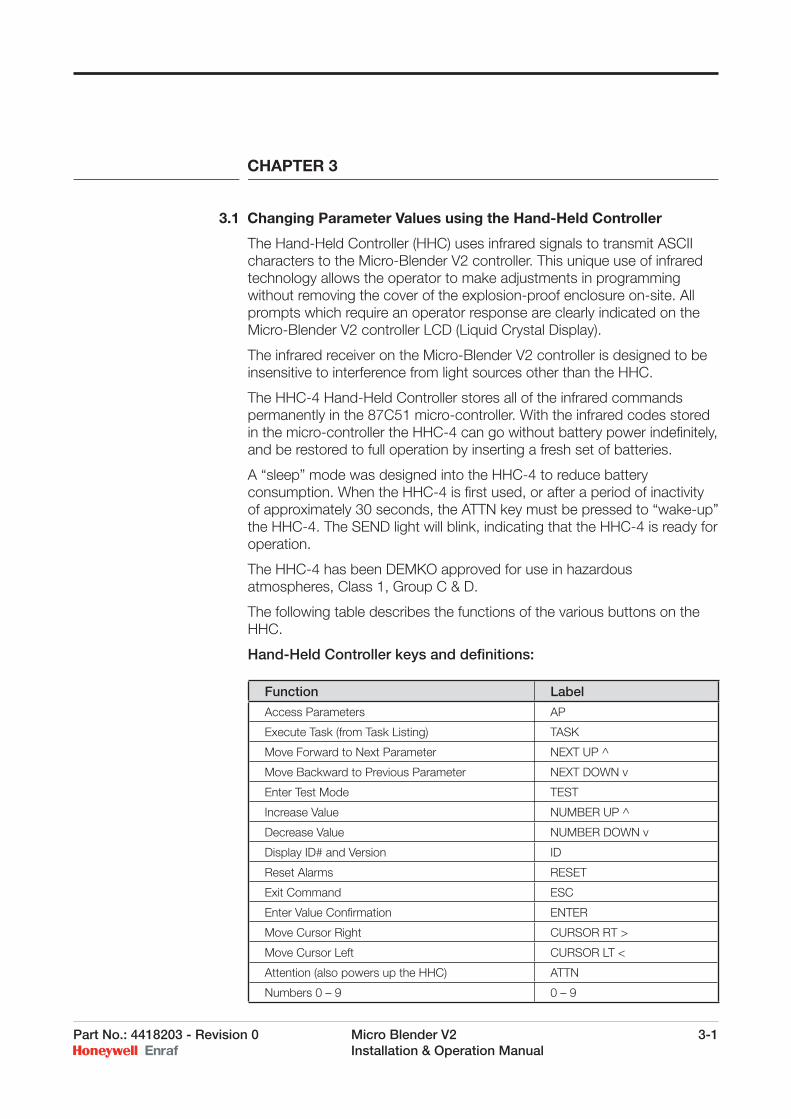
The following table describes the functions of the various buttons on the HHC.
Hand-Held Controller keys and defi nitions:
Function Label
Access Parameters AP
Execute Task (from Task Listing) TASK
Move Forward to Next Parameter NEXT UP ^
Move Backward to Previous Parameter NEXT DOWN v
Enter Test Mode TEST
Increase Value NUMBER UP ^
Decrease Value NUMBER DOWN v
Display ID# and Version ID
Reset Alarms RESET
Exit Command ESC
Enter Value Confi rmation ENTER
Move Cursor Right CURSOR RT >
Move Cursor Left CURSOR LT <
Attention (also powers up the HHC) ATTN
Numbers 0 – 9 0 – 9
3-2 Micro Blender V2 Part No.: 4418203 - Revision 0 Installation & Operation Manual
Chapter 3
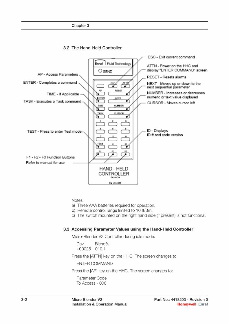
3.2 The Hand-Held Controller
Notes:a) Three AAA batteries required for operation.b) Remote control range limited to 10 ft/3m.c) The switch mounted on the right hand side (if present) is not functional.
3.3 Accessing Parameter Values using the Hand-Held Controller
Micro-Blender V2 Controller during idle mode:
Dev Blend% +00025 010.1
Press the [ATTN] key on the HHC. The screen changes to:
ENTER COMMAND
Press the [AP] key on the HHC. The screen changes to:
Parameter Code To Access - 000
Part No.: 4418203 - Revision 0 Micro Blender V2 3-3 Installation & Operation Manual
Enter the Parameter Code or number desired. The numbers may be entered from the numeric keypad on the HHC, or the Parameter Codes may be incrementally stepped through by pressing the [NEXT] bar key on the HHC. When the desired Parameter Code is displayed, press the [ENTER] key. The screen changes to:
Parameter->010 002.0
The top right-hand area of the display shows the Parameter number. The bottom line displays the current value stored for that Parameter. At this time, a combination of cursor bar and numeric keys may be used to change the current value into the new value desired. Upon completion of the change, the user presses the [ENTER] key. The screen changes to:
Save? 003.5 (1) = Yes (2) = No
In the top right-hand area of the display is the new value you are about to store. Press either the [1] or [2] keys on the HHC as needed. The controller then returns to the Access Parameter mode:
Parameter Code To Access - 000
When the desired changes have been completed, use the [ESC] key to exit the program setup mode. If the program setup mode is not exited, the controller will eventually time out and return to the run mode display on its own.
Chapter 3

3-4 Micro Blender V2 Part No.: 4418203 - Revision 0 Installation & Operation Manual
Chapter 3
Intentionally left blank.
Part No.: 4418203 - Revision 0 Micro Blender V2 4-1 Installation & Operation Manual
CHAPTER 4
4.1 Parameter Table
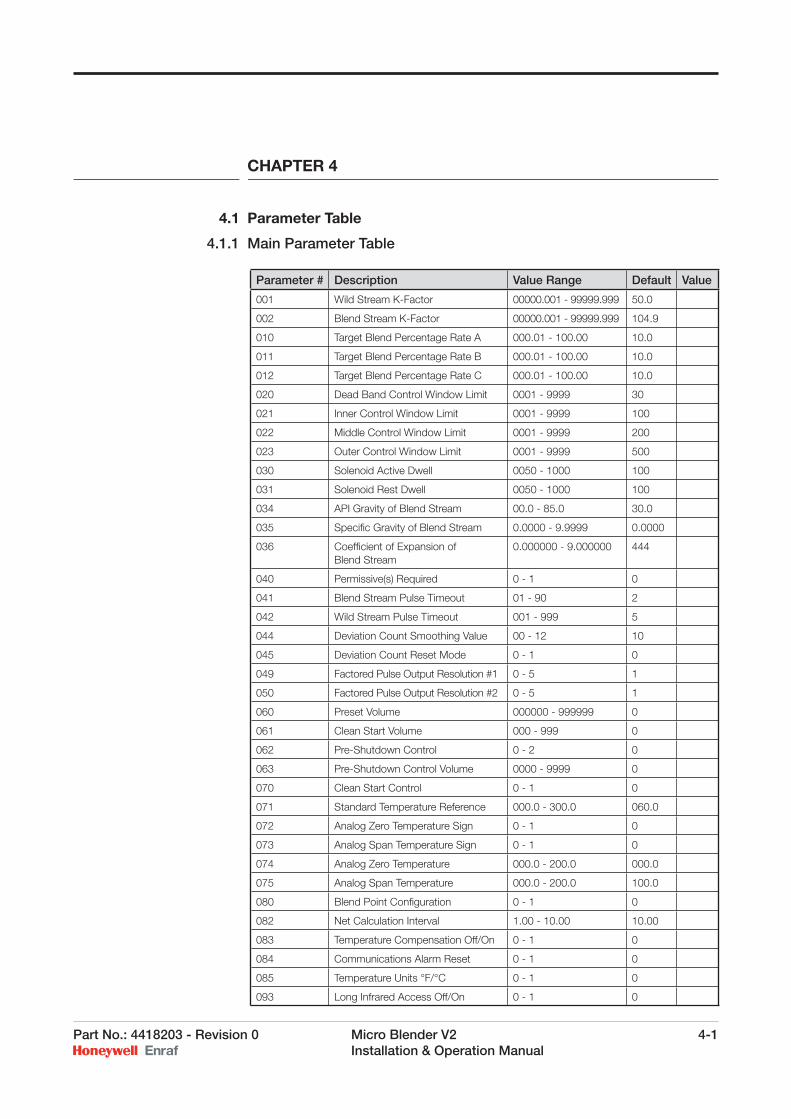
4.1.1 Main Parameter Table
Parameter # Description Value Range Default Value
001 Wild Stream K-Factor 00000.001 - 99999.999 50.0
002 Blend Stream K-Factor 00000.001 - 99999.999 104.9
010 Target Blend Percentage Rate A 000.01 - 100.00 10.0
011 Target Blend Percentage Rate B 000.01 - 100.00 10.0
012 Target Blend Percentage Rate C 000.01 - 100.00 10.0
020 Dead Band Control Window Limit 0001 - 9999 30
021 Inner Control Window Limit 0001 - 9999 100
022 Middle Control Window Limit 0001 - 9999 200
023 Outer Control Window Limit 0001 - 9999 500
030 Solenoid Active Dwell 0050 - 1000 100
031 Solenoid Rest Dwell 0050 - 1000 100
034 API Gravity of Blend Stream 00.0 - 85.0 30.0
035 Specifi c Gravity of Blend Stream 0.0000 - 9.9999 0.0000
036 Coeffi cient of Expansion of Blend Stream
0.000000 - 9.000000 444
040 Permissive(s) Required 0 - 1 0
041 Blend Stream Pulse Timeout 01 - 90 2
042 Wild Stream Pulse Timeout 001 - 999 5
044 Deviation Count Smoothing Value 00 - 12 10
045 Deviation Count Reset Mode 0 - 1 0
049 Factored Pulse Output Resolution #1 0 - 5 1
050 Factored Pulse Output Resolution #2 0 - 5 1
060 Preset Volume 000000 - 999999 0
061 Clean Start Volume 000 - 999 0
062 Pre-Shutdown Control 0 - 2 0
063 Pre-Shutdown Control Volume 0000 - 9999 0
070 Clean Start Control 0 - 1 0
071 Standard Temperature Reference 000.0 - 300.0 060.0
072 Analog Zero Temperature Sign 0 - 1 0
073 Analog Span Temperature Sign 0 - 1 0
074 Analog Zero Temperature 000.0 - 200.0 000.0
075 Analog Span Temperature 000.0 - 200.0 100.0
080 Blend Point Confi guration 0 - 1 0
082 Net Calculation Interval 1.00 - 10.00 10.00
083 Temperature Compensation Off/On 0 - 1 0
084 Communications Alarm Reset 0 - 1 0
085 Temperature Units °F/°C 0 - 1 0
093 Long Infrared Access Off/On 0 - 1 0
4-2 Micro Blender V2 Part No.: 4418203 - Revision 0 Installation & Operation Manual
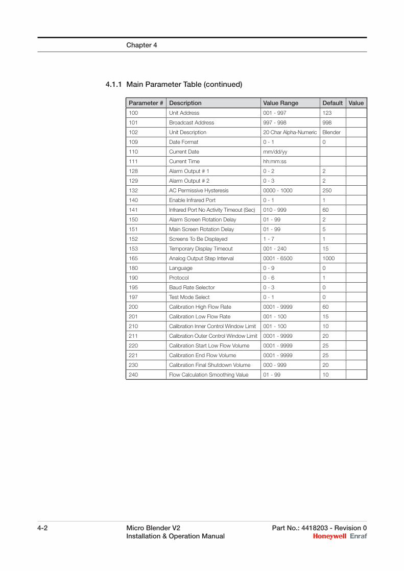
4.1.1 Main Parameter Table (continued)
Parameter # Description Value Range Default Value
100 Unit Address 001 - 997 123
101 Broadcast Address 997 - 998 998
102 Unit Description 20 Char Alpha-Numeric Blender
109 Date Format 0 - 1 0
110 Current Date mm/dd/yy
111 Current Time hh:mm:ss
128 Alarm Output # 1 0 - 2 2
129 Alarm Output # 2 0 - 3 2
132 AC Permissive Hysteresis 0000 - 1000 250
140 Enable Infrared Port 0 - 1 1
141 Infrared Port No Activity Timeout (Sec) 010 - 999 60
150 Alarm Screen Rotation Delay 01 - 99 2
151 Main Screen Rotation Delay 01 - 99 5
152 Screens To Be Displayed 1 - 7 1
153 Temporary Display Timeout 001 - 240 15
165 Analog Output Step Interval 0001 - 6500 1000
180 Language 0 - 9 0
190 Protocol 0 - 6 1
195 Baud Rate Selector 0 - 3 0
197 Test Mode Select 0 - 1 0
200 Calibration High Flow Rate 0001 - 9999 60
201 Calibration Low Flow Rate 001 - 100 15
210 Calibration Inner Control Window Limit 001 - 100 10
211 Calibration Outer Control Window Limit 0001 - 9999 20
220 Calibration Start Low Flow Volume 0001 - 9999 25
221 Calibration End Flow Volume 0001 - 9999 25
230 Calibration Final Shutdown Volume 000 - 999 20
240 Flow Calculation Smoothing Value 01 - 99 10
Chapter 4
Part No.: 4418203 - Revision 0 Micro Blender V2 4-3 Installation & Operation Manual
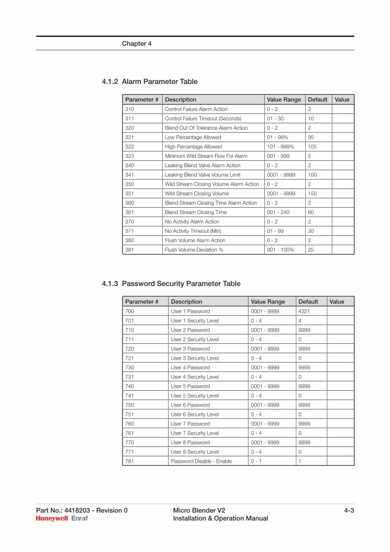
4.1.2 Alarm Parameter Table
4.1.3 Password Security Parameter Table
Chapter 4
Parameter # Description Value Range Default Value
310 Control Failure Alarm Action 0 - 2 2
311 Control Failure Timeout (Seconds) 01 - 30 10
320 Blend Out Of Tolerance Alarm Action 0 - 2 2
321 Low Percentage Allowed 01 - 99% 95
322 High Percentage Allowed 101 - 999% 105
323 Minimum Wild Stream Flow For Alarm 001 - 999 5
340 Leaking Blend Valve Alarm Action 0 - 2 2
341 Leaking Blend Valve Volume Limit 0001 - 9999 100
350 Wild Stream Closing Volume Alarm Action 0 - 2 2
351 Wild Stream Closing Volume 0001 - 9999 150
360 Blend Stream Closing Time Alarm Action 0 - 2 2
361 Blend Stream Closing Time 001 - 240 60
370 No Activity Alarm Action 0 - 2 2
371 No Activity Timeout (Min) 01 - 99 30
380 Flush Volume Alarm Action 0 - 2 2
381 Flush Volume Deviation % 001 - 100% 25
Parameter # Description Value Range Default Value
700 User 1 Password 0001 - 9999 4321
701 User 1 Security Level 0 - 4 4
710 User 2 Password 0001 - 9999 9999
711 User 2 Security Level 0 - 4 0
720 User 3 Password 0001 - 9999 9999
721 User 3 Security Level 0 - 4 0
730 User 4 Password 0001 - 9999 9999
731 User 4 Security Level 0 - 4 0
740 User 5 Password 0001 - 9999 9999
741 User 5 Security Level 0 - 4 0
750 User 6 Password 0001 - 9999 9999
751 User 6 Security Level 0 - 4 0
760 User 7 Password 0001 - 9999 9999
761 User 7 Security Level 0 - 4 0
770 User 8 Password 0001 - 9999 9999
771 User 8 Security Level 0 - 4 0
781 Password Disable - Enable 0 - 1 1
4-4 Micro Blender V2 Part No.: 4418203 - Revision 0 Installation & Operation Manual
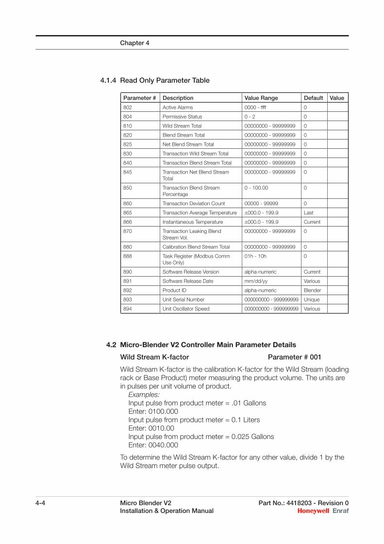
4.1.4 Read Only Parameter Table
4.2 Micro-Blender V2 Controller Main Parameter Details
Wild Stream K-factor Parameter # 001
Wild Stream K-factor is the calibration K-factor for the Wild Stream (loading rack or Base Product) meter measuring the product volume. The units are in pulses per unit volume of product. Examples: Input pulse from product meter = .01 Gallons Enter: 0100.000 Input pulse from product meter = 0.1 Liters Enter: 0010.00 Input pulse from product meter = 0.025 Gallons Enter: 0040.000
To determine the Wild Stream K-factor for any other value, divide 1 by the Wild Stream meter pulse output.
Chapter 4
Parameter # Description Value Range Default Value
802 Active Alarms 0000 - ffff 0
804 Permissive Status 0 - 2 0
810 Wild Stream Total 00000000 - 99999999 0
820 Blend Stream Total 00000000 - 99999999 0
825 Net Blend Stream Total 00000000 - 99999999 0
830 Transaction Wild Stream Total 00000000 - 99999999 0
840 Transaction Blend Stream Total 00000000 - 99999999 0
845 Transaction Net Blend Stream Total
00000000 - 99999999 0
850 Transaction Blend Stream Percentage
0 - 100.00 0
860 Transaction Deviation Count 00000 - 99999 0
865 Transaction Average Temperature +000.0 - 199.9 Last
866 Instantaneous Temperature +000.0 - 199.9 Current
870 Transaction Leaking Blend Stream Vol.
00000000 - 99999999 0
880 Calibration Blend Stream Total 00000000 - 99999999 0
888 Task Register (Modbus Comm Use Only)
01h - 10h 0
890 Software Release Version alpha-numeric Current
891 Software Release Date mm/dd/yy Various
892 Product ID alpha-numeric Blender
893 Unit Serial Number 000000000 - 999999999 Unique
894 Unit Oscillator Speed 000000000 - 999999999 Various
Part No.: 4418203 - Revision 0 Micro Blender V2 4-5 Installation & Operation Manual
Blend Stream K-factor Parameter # 002
Blend Stream K-factor is the calibration K-factor for the meter measuring the Blend Stream product. The units are in pulses per unit of volume of Blend Product. Examples: When calibrated meter K-factor equals 250 enter: 0250.000 When calibrated meter K-factor equals 480.120 enter: 0480.120
*Note: This value may be automatically calculated using the test function. Refer to the test procedure outline in this manual for further detail.
Target Blend Percentage Rate A Parameter # 010
The Target Blend Percentage determines the ratio of the Blend Product to the combined total fl ow. The ratio is expressed as a percentage. This blend percentage is selected by a high or true signal on the Permissive A status input or via communications. Example: For a blend ratio of 10% enter: 010.00
Target Blend Percentage Rate B Parameter # 011
The Target Blend Percentage determines the ratio of the Blend Product to the combined total fl ow. The ratio is expressed as a percentage. This blend percentage is selected by a high or true signal on the Permissive B status input or via communications. Example: For a blend ratio of 10% enter: 010.00
Target Blend Percentage Rate C Parameter # 012
The Target Blend Percentage determines the ratio of the Blend Product to the combined total fl ow. The ratio is expressed as a percentage. This blend percentage is selected by a high or true signal on the Permissive C status input or via communications. Example: For a blend ratio of 10% enter: 010.00
Dead Band Window Limit Parameter # 020
The Dead Band Window Limit establishes a distance from zero in the error count. When the count value is less than this number, the control from the controller is locked. No correction is made to the blend stream control valve. This value effectively establishes the “dead band” in which the error count can drift without correction. The dead band is plus or minus this value.
Inner Control Window Limit Parameter # 021
The Inner Control Window Limit sets a distance from zero in the error count. This value should be greater than Parameter 020 and less than Parameter 022. When the count value is greater than the Parameter 020
Chapter 4
4-6 Micro Blender V2 Part No.: 4418203 - Revision 0 Installation & Operation Manual
value and less that this value, the controller uses one-half the Active Dwell (Parameter 030) value and double the Rest Dwell (Parameter 031) value when controlling the blend stream control valve.
*Note: Both the positive and negative deviation counts use the same Inner Control Limit value to determine valve control.
Middle Window Limit Parameter # 022
The Middle Window Limit sets a distance from zero in the error count. This value should be greater than Parameter 021 and less than Parameter 023. When the count value is greater than the Parameter 021 value and less than this value, the controller uses the Active Dwell (Parameter 030) value and the Rest Dwell (Parameter 031) value when controlling the blend stream control valve.
Outer Control Window Limit Parameter # 023
The Outer Control Limit sets a distance from zero in the error count. This value should be greater than Parameter 022. When the count value is greater than the Parameter 022 value and less than this value, the controller uses double the Active Dwell (Parameter 030) value and one-half the Rest Dwell (Parameter 031) value when controlling the blend stream control valve. Deviation counts in excess of this value cause the accumulation of time in the Control Failure Alarm timer (Parameter 311). The deviation must return to less than this value within the time limit to prevent an alarm.
Solenoid Active Dwell Parameter # 030
The Solenoid Active Dwell parameter determines how long a solenoid is held in the state (energized or de-energized) that allows fl ow through it. In the case of the normally closed solenoid, it is the energized open state. In the case of the normally open solenoid, it is the de-energized open state. Values are in milliseconds.
Solenoid Rest Dwell Parameter # 031
The Solenoid Rest Dwell parameter determines how long a solenoid is held in the state (energized or de-energized) that stops fl ow through it. In the case of the normally closed solenoid, it is the de-energized closed state. In the case of the normally open solenoid, it is the energized closed state. Values are in milliseconds.
API Gravity of Product Parameter # 034
The API Gravity of Product parameter is used in a lookup table to fi nd the correct temperature compensation factors when performing temperature compensation. Changing this value changes parameter 035 & 036 automatically.
Examples:To have the controller assign a value of 30.5 enter 30.5.To have the controller assign a value of 40.0 enter 40.0
Chapter 4
Part No.: 4418203 - Revision 0 Micro Blender V2 4-7 Installation & Operation Manual
Specifi c Gravity of Product Parameter # 035
As an alternative to using API gravities in Parameter # 034, this parameter allows direct entry of the Specifi c Gravity of Blend Product. The Specifi c Gravity is in grams per cubic centimeter. Changing this value changes parameter 034 & 036 automatically.
Coeffi cient of Expansion of Product Parameter # 036
As an alternative to using API gravities or Specifi c Gravities above, this parameter allows the use of a Coeffi cient of Expansion when known. The units are in parts per million per degree F/C. Changing this value changes parameter 034 & 035 automatically.
Permissive(s) Required Parameter # 040
The Permissive(s) Required parameter determines how the unit is to be permitted. The Micro-Blender V2 Controller may be permitted using only hardware or software (value = 0), or require both hardware and software (value = 1).
Blend Stream Pulse Time Out Parameter # 041
The Blend Stream Pulse Time Out parameter determines how long the deviation counter remains active after blend pulses stop and permissive is removed. The time is in seconds. Once permissive is removed the Micro-Blender V2 Controller will not report a Control Failure Alarm. The deviation counter stops when the Blend Stream Pulse Time Out counter has timed out and the permissive is no longer active. After permissive is removed, the blend control valve will immediately be closed. Although the Micro-Blender V2 Controller will not attempt to correct a blend based on the pulses received after the permissive is removed, the remaining pulses are used to determine fi nal blend percentage.
Wild Stream Pulse Time Out Parameter # 042
The Wild Stream Pulse Time Out parameter determines how long the Micro-Blender V2 Controller delays after removal of permissive and the absence of Wild Stream Pulses before determining fi nal transaction totals. This time is in seconds.
Deviation Count Smoothing Value Parameter # 044
The Deviation Count Smoothing Value determines how many successive samples are averaged before calculating an actual deviation count. This parameter eliminates incremental dips and spikes in the deviation count.
Note: This value is factory set and should not be changed.
Deviation Count Reset Mode Parameter # 045
The Deviation Count Reset Mode determines when the deviation count is reset. The available choices are at the start of permissive and only when the Blend Out of Tolerance Alarm (Parameter #320) is reset. Set this value = 0 for “Do not reset count on loss of permissive”. Set this value = 1 for “Reset deviation count on loss of permissive”.
Chapter 4
4-8 Micro Blender V2 Part No.: 4418203 - Revision 0 Installation & Operation Manual
Factored Pulse Output Parameters # 049 & 050
The Factored Pulse Output resolution parameter determines the number of pulses transmitted for each unit volume of Blend Stream fl ow. The resolution can be programmed to allow the Micro-Blender V2 to output 1 pulse (= 0), 10 pulses (= 1), or 100 (= 2) pulses per unit volume of the Blend Stream fl ow. A raw pulse (no factoring) output is selected by setting this parameter value to (3). Units are determined by the Blend Stream K-factor (Parameter # 002). Setting 049 = 4, disables the output leaving Factored Pulse Output 1
turned ON . Setting 049 = 5, disables the output leaving Factored Pulse Output 1
turned OFF . Setting 050 = 4, disables the output leaving Factored Pulse Output 2
turned ON . Setting 050 = 5, disables the output leaving Factored Pulse Output 2
turned OFF .
Preset Volume Parameter #060
This parameter stores the volume of product to be loaded during the transaction. This parameter is only used if Parameter #061 is non-zero. The blend percentage is adjusted according to the amount entered into this parameter, in order to increase the amount of blend stream product going in the load prior to the clean start fl ush at the end of the delivery. See the section on “Clean Start” in this manual.
Clean Start Volume Parameter #061
The Low Flow Product Volume is the gallons or liters of product that is to remain blend free or “clean” when the fl ow stops. This value is typically set larger than the volume between the blend injection point on the wild stream product line and the end of the loading arm coupling. The blender electronics uses this number, the value in Parameter # 060, and the recipe to determine what blend percentage to use at the start of the transaction. Setting this value to zero disables Clean Start.
Pre-Shutdown Control Parameter #062
This parameter is only used if Parameter #061 is non-zero. This parameter selects between three(3) modes of operation. If 062 = 0, and in Clean Start then no Pre-Shutdown Closure Volume is
to be used in the shutdown process. If 062 = 1, and in Clean Start then a Fixed Pre-Shutdown Closure
Volume is to be used in the shutdown process. If 062 = 2, and in Clean Start then a Calculated Pre-Shutdown Closure
Volume is to be used in the shutdown process.
Pre-Shutdown Closure Volume Parameter #063
This parameter is only used if Parameter #061 is non-zero. This parameter contains the Pre Shutdown volume of product used to determine when to start the shutdown process. For Example if 063 = 0200, then the shutdown will occur 200 Gallons/Liters before the end load volume.
Chapter 4
Part No.: 4418203 - Revision 0 Micro Blender V2 4-9 Installation & Operation Manual
Clean Start Control Parameter #070
The Clean Start Control parameter determines how the blender knows when to stop blending.
Setting Parameter # 070 = 0 will allow the blender to stop blending when the permissive signal is removed. The blender then expects the volume in Parameter # 061 to fl ow, bringing the blend percentage down to the target percentage.
Setting Parameter # 070 = 1 allows the blender to monitor the delivered volume and determine when to stop the blend, regardless of the state of the permissive signal.
Standard Temperature Reference Parameter # 071
This parameter stores the value of temperature that the volume of blend stream product will be corrected to. The value is most commonly set to 60°F (15°C).
Analog Zero Temperature Sign Parameter # 072
The Analog Zero Temperature Sign uses a zero or a one to indicate whether the value in Parameter # 074 is a negative number or a positive number. Set this parameter to a zero when the value in Parameter # 074 is positive. Set this parameter to a one when the value in Parameter # 074 is negative.
Analog Span Temperature Sign Parameter # 073
The Analog Zero Temperature Sign uses a zero or a one to indicate whether the value in Parameter # 075 is a negative number or a positive number. Set this parameter to a zero when the value in Parameter # 075 is positive. Set this parameter to a one when the value in Parameter # 075 is negative.
Analog Zero Temperature Parameter # 074
The temperature value stored in this parameter is the value used to scale the temperature range at 4.00 mA input on the analog input channel. This value must match the transmitter ‘zero’ temperature value.
Analog Span Temperature Parameter # 075
The temperature value stored in this parameter is the value used to scale the temperature range at 20.00 mA input on the analog input channel. This value must match the transmitter ‘span’ temperature.
Blend Point Relative to Wild Stream Parameter # 080
The Blend Point Relative to Wild Stream Parameter determines how calculations are made on the Blend Percentage calculation. A zero in this parameter confi gures the blender to have the Blend Stream enter the Wild Stream at a point that is upstream from the Wild Steam meter. A one in this parameter confi gures the blender to have the Blend Stream enter the Wild Stream downstream of the Wild Stream meter.
For Upstream blending enter: 0 For Downstream blending enter: 1
Chapter 4
4-10 Micro Blender V2 Part No.: 4418203 - Revision 0 Installation & Operation Manual
Net Calculation Interval Parameter # 082
This parameter determines how often (volumetrically) the net calculation if performed on the gross volume totals. It can be set from 1.00 unit volume to 10.00 unit volumes (actual volume is dependent upon the k-factor in Parameter # 002). When temperature compensation is turned on (Parameter # 083 = 1), each time that the volume in this parameter is dispensed, the controller will calculate the temperature corrected volume for that amount and add it to the transaction and grand total volumes.
Temperature Compensation Off/On Parameter # 083
Setting this parameter value to a zero (0) disables temperature compensation in the blender. The blend percentage attained will be based upon gross volume. If the value in this parameter is set to a one (1), the blend percentage will be adjusted for the temperature of the blend stream product corrected to a standard temperature.
Notes when using temperature compensation:1. A blend stream temperature transmitter must be connected to the
analog input and must be properly scaled to the controller analog input. (Refer to Parameter #’s 074 & 075)
2. The wild stream pacing pulse used by the Micro-Blender V2 Controller must be a net (gst) volume pulse stream.
Communications Alarm Reset Parameter # 084
When this parameter is set to zero (default value) the blender will ignore the communications alarm reset command when the blender is permitted, and reset alarms when un-permitted. When this parameter is set to one (1), the blender will always reset the alarm regardless of the permissive state.
Temperature Units °F/°C Parameter # 085
By changing this parameter, the user can select whether the temperature entries for the controller are in degrees Fahrenheit or Celsius. A zero (0) selects °F. An entry of one (1) selects °C.
Long Infrared Access Parameter # 093
In a few installations of Honeywell Enraf controllers, it has been reported that sunlight or strong artifi cial light sources can “unlock” the infrared port the same way as pressing the ATTN key on the hand held controller. If this occurs, parameter values could accidentally be changed. It should be noted that this is an EXTREMELY rare possibility, but could happen.
The Long Infrared Access parameter enables or disables an extended login sequence of characters for the infrared communications port on the bezel of the Micro-Blender V2. Using an extended login character sequence raises the odds of a random pattern of interference matching the correct login sequence to astronomical levels.
Setting Parameter # 093 to a zero (default) uses the short login sequence of pressing only the [ATTN] key on the remote to get to the ENTER COMMAND screen.
Chapter 4
Part No.: 4418203 - Revision 0 Micro Blender V2 4-11 Installation & Operation Manual
Setting Parameter # 093 to a one (1) makes the controller require the long login sequence of four buttons being pressed. Use [ATTN], [F1], [F2], [F3] to get to the ENTER COMMAND screen.
Unit Address Parameter # 100
The Unit Address parameter is the primary address of the Micro-Blender V2 Controller. The primary address is the value used to identify a particular unit to the master computer. This 3 digit number must be unique to each unit on a communication loop.
Broadcast Address Parameter # 101
The Broadcast Address parameter is the secondary address recognized by the Micro-Blender V2 Controller. It is not necessarily unique to any particular unit. This address is used by the master if it wants to transmit a command to more than one unit, simultaneously. The Micro-Blender V2 Controller will not respond to a message addressed to its Broadcast Address.
Unit Description Parameter # 102
The Unit Description fi eld is a free form alphanumeric string used to help identify the unit to the user. All ASCII characters between 32 hex and 7A hex are valid, with the exception of the reserved character 3b hex (semicolon). This parameter must be set using the serial communications port. *20 hex (space character) is a legal value
Date Format Parameter # 109
A setting of zero in this parameter uses mm/dd/yy format in the transaction storage. A setting of one uses dd/mm/yy. Caution: Dates stored in the transaction fi le before the change and after will not be consistent and may cause confusion.
Current Date Parameter # 110
This parameter stores the current date. It is formatted mm/dd/yy.
Current Time Parameter # 111
This parameter stores the current time. It is formatted hh:mm:ss.
Alarm Output Control Parameter # 128, 129
The Alarm Output Control parameter determines the operation of the alarm output triac. When a value of 0 is selected, the Alarm Output is normally off (0 volts output) and turns on (supply voltage present) when in alarm. When a value of 1 is entered, this function is reversed.
When using the Micro-Blender V2 Controller as a replacement for the WB-1091-DP blender chassis, the alarm output is used as a permissive control to the differential pressure circuit aboard. This output must drop power to the solenoids when the permissive input turns off in order to de-energize the solenoids properly.
Chapter 4
4-12 Micro Blender V2 Part No.: 4418203 - Revision 0 Installation & Operation Manual
A third operational logic includes the permissive enable status. This allows the alarm output to act as a secondary safety valve control signal. If 128 or 129 = 0, the alarm triac output is normally off with no alarms
present. If 128 or 129 = 1, the alarm triac output is normally on with no alarms
present. If 128 or 129 = 2, the alarm triac is normally on if no alarms are
present AND the unit is permitted. The output goes off upon alarm OR permissive off.
If 129 = 3, the Triac #2 output energizes when the Test Mode is entered and turns off when the Test Mode is exited.
AC Permissive Hysteresis Parameter # 132
The AC Permissive Hysteresis parameter determines the length of time required for the AC permissive to change state and remain in that state before the Micro-Blender V2 Controller will recognize the change. This parameter is useful in preventing contact bounce. Units are in milliseconds.
Enable Infrared Port Parameter # 140
The Enable Infrared Port parameter enables or disables the infrared communications port on the bezel of the Micro-Blender V2 Controller. Disabling the port prohibits the user from accessing the Micro-Blender V2 Controller with the Hand-Held controller. This parameter must be set using the serial communications port.
Infrared Port No Activity Parameter # 141
The Infrared Port No Activity Timeout sets the time the Micro-Blender V2 Controller will remain in the local programming mode without communication to the infrared port. When the port times out, the Micro-Blender V2 Controller will return to the idle mode. Examples: To have the infrared port timeout after 10 seconds enter: 010 To have the infrared port timeout after 45 seconds enter: 045
LCD Alarm Screen Rotation Parameter # 150
The LCD Alarm Screen Rotation Delay parameter sets the length of time the alarm information will remain on the LCD display of the Micro-Blender V2 Controller before the next one, if any, is displayed. If more than one alarm is active, the alarm screens are displayed in rotation.
LCD Main Screen Rotation Parameter # 151
The LCD Main Screen Rotation Delay parameter sets the length of time the main screen will remain on the LCD display of the Micro-Blender V2 Controller before the next one, if any, is displayed. If confi gured for multiple screens (Parameter #152), the screens are displayed in rotation.
Chapter 4
Part No.: 4418203 - Revision 0 Micro Blender V2 4-13 Installation & Operation Manual
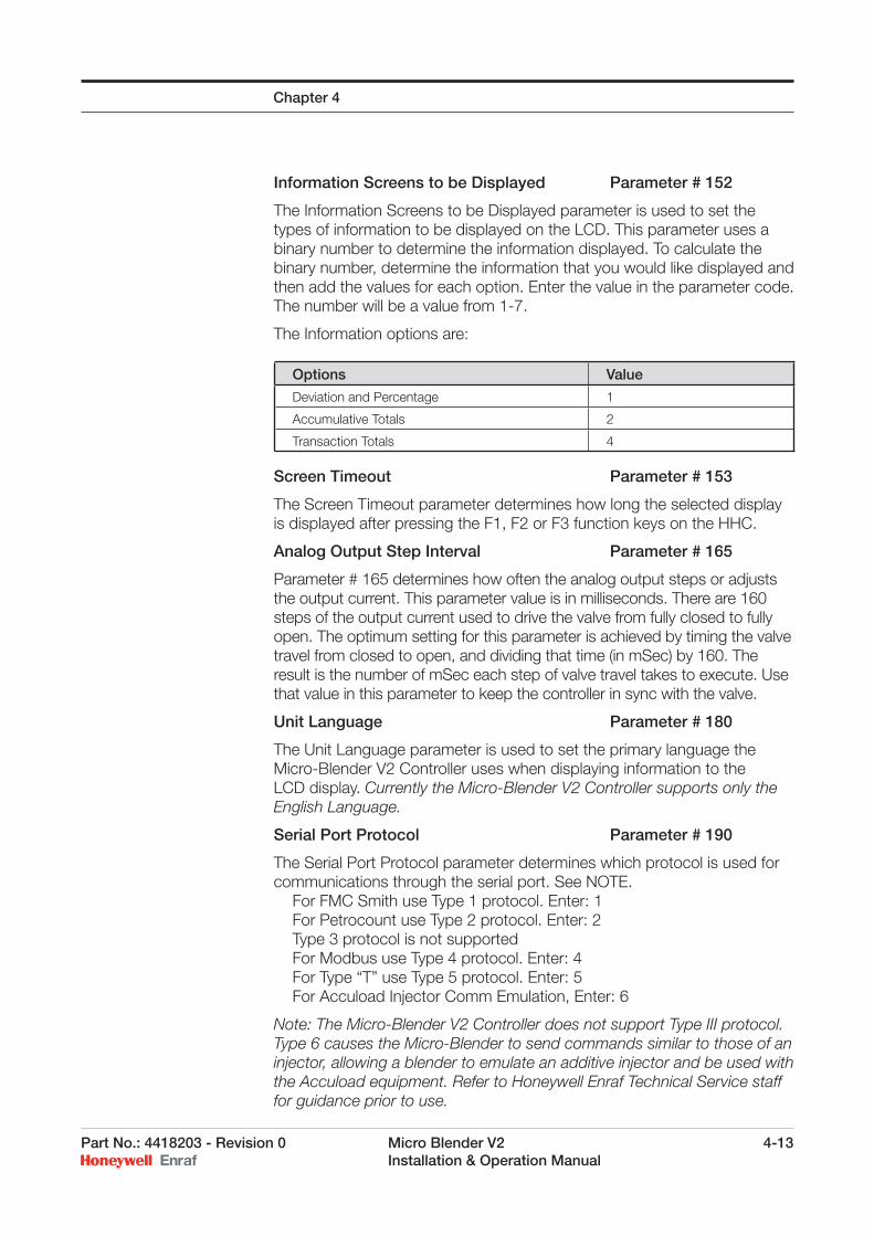
Information Screens to be Displayed Parameter # 152
The Information Screens to be Displayed parameter is used to set the types of information to be displayed on the LCD. This parameter uses a binary number to determine the information displayed. To calculate the binary number, determine the information that you would like displayed and then add the values for each option. Enter the value in the parameter code. The number will be a value from 1-7.
The Information options are:
Screen Timeout Parameter # 153
The Screen Timeout parameter determines how long the selected display is displayed after pressing the F1, F2 or F3 function keys on the HHC.
Analog Output Step Interval Parameter # 165
Parameter # 165 determines how often the analog output steps or adjusts the output current. This parameter value is in milliseconds. There are 160 steps of the output current used to drive the valve from fully closed to fully open. The optimum setting for this parameter is achieved by timing the valve travel from closed to open, and dividing that time (in mSec) by 160. The result is the number of mSec each step of valve travel takes to execute. Use that value in this parameter to keep the controller in sync with the valve.
Unit Language Parameter # 180
The Unit Language parameter is used to set the primary language the Micro-Blender V2 Controller uses when displaying information to the LCD display. Currently the Micro-Blender V2 Controller supports only the English Language.
Serial Port Protocol Parameter # 190
The Serial Port Protocol parameter determines which protocol is used for communications through the serial port. See NOTE. For FMC Smith use Type 1 protocol. Enter: 1 For Petrocount use Type 2 protocol. Enter: 2 Type 3 protocol is not supported For Modbus use Type 4 protocol. Enter: 4 For Type “T” use Type 5 protocol. Enter: 5 For Accuload Injector Comm Emulation, Enter: 6
Note: The Micro-Blender V2 Controller does not support Type III protocol.Type 6 causes the Micro-Blender to send commands similar to those of an injector, allowing a blender to emulate an additive injector and be used with the Accuload equipment. Refer to Honeywell Enraf Technical Service staff for guidance prior to use.
Chapter 4
Options Value
Deviation and Percentage 1
Accumulative Totals 2
Transaction Totals 4
4-14 Micro Blender V2 Part No.: 4418203 - Revision 0 Installation & Operation Manual
Baud Rate Selector Parameter # 195
The Baud Rate selector parameter is used to select the baud rate for the communication port. Examples: Enter: 0 for 1200 Baud Enter: 1 for 2400 Baud Enter: 2 for 9600 Baud Enter: 3 for 19200 Baud
Display I/O Test Mode Parameter # 197
This parameter is used for factory testing. The default value for this parameter is zero and should remain zero within installed blenders.
CAUTION: Changing this value to a one (1) may result in unpredictable operation of the blender!
4.3 Micro-Blender V2 Controller Calibration Mode Parameter Details
The following valve control parameters are functional only during the test/calibration mode. During normal operation of the Micro-Blender V2 Controller these valve control parameters will be ignored.
High Flow Rate Parameter # 200
The High Flow Rate parameter sets the maximum fl ow rate that is allowed through the Blend Stream. Flow rate is determined on a per minute basis.
Low Flow Rate Parameter # 201
The Low Flow Rate parameter sets the minimum fl ow rate that is allowed through the Blend Stream. Flow rate is determined on a per minute basis.
Note: Make sure the minimum fl ow rate programmed is not below the minimum required for accuracy.
Inner Flow Rate Control Window Parameter # 210
For calibration fl ow purposes there are only two control windows in the Micro-Blender V2 Controller. Refer to the section on Operation for details on how window limits control the blend stream control valve. The Inner Flow Rate Control Window parameter determines when the digital blend control valve is pulsed open or closed. If the fl ow rate is determined to be less than the value set by this parameter, the control valve will remain locked at the current fl ow rate. If the fl ow rate is determined to be outside the value set by this parameter the Micro-Blender V2 Controller will signal the control valve to either open or close, depending if the deviation count is positive or negative. The maximum value for the Inner Flow Rate Control Window must not be greater than the Outer Flow Rate Control Window (Parameter # 211). Flow rate is determined on a per minute basis.
Chapter 4
Part No.: 4418203 - Revision 0 Micro Blender V2 4-15 Installation & Operation Manual
Outer Flow Rate Control Window Parameter # 211
For calibration fl ow purposes there are only two control windows in the Micro-Blender V2 Controller. Refer to the section on Operation for details on how these window limits control the blend stream control valve. The Outer Flow Rate Control Window parameter determines when the digital blend control valve is continuously signaled to open or close. If the fl ow rate is determined to be less than the value set by this parameter, the control valve will remain under control of Parameter 210. If the fl ow rate is determined to be outside the value set by this parameter the Micro-Blender V2 Controller will signal the control valve to either open or close by holding the proper solenoid continuously open or closed, depending if the deviation count is positive or negative. The maximum value for the Outer Flow Rate Control Window must be greater than the inner Flow Rate Control Window (Parameter # 210). Flow rate is determined on a per minute basis.
Start Low Flow Volume Parameter # 220
The Start Low Flow Volume parameter sets the volume of fuel that will be delivered at the Low Flow Rate (Parameter #201) during the calibration procedure before the Micro-Blender V2 Controller begins the transition to High Flow Rate (Parameter # 200).
End Low Flow Volume Parameter # 221
The End Low Flow Volume parameter determines the number of unit volumes of fuel before the end of delivery when the Micro-Blender V2 Controller will transition from the high fl ow rate to the low fl ow rate. Test Volume enter: 0050
Note: This parameter is only applicable to the calibration procedure.
Final Shut Down Volume Parameter # 230
The Final Shut Down Volume parameter determines the number of unit volumes of fuel before the end of delivery when the Micro-Blender V2 Controller will signal the digital blend control valve to close. Examples: To have the Micro-Blender V2 Controller begin valve closure 5 Gallons
before the end of the test volume enter: 05.0 To have the Micro-Blender V2 Controller begin valve closure 2 Gallons
before the end of the test volume enter: 02.0
Note: This parameter is only applicable to the calibration procedure.
Flow Calculation Smoothing Value Parameter # 240
The Flow Calculation Smoothing Value parameter determines the number of reads the Micro-Blender V2 Controller uses to determine a fl ow rate calculation.
Note: This parameter is factory set and should not be changed.
Chapter 4

4-16 Micro Blender V2 Part No.: 4418203 - Revision 0 Installation & Operation Manual
Intentionally left blank.
Chapter 4
Part No.: 4418203 - Revision 0 Micro Blender V2 5-1 Installation & Operation Manual
CHAPTER 5
5.1 Micro-Blender V2 Controller Alarm Parameter Details
The Micro-Blender V2 continuously monitors the blending process and can be programmed to provide an alarm output in the event that an alarm condition occurs. The Micro-Blender V2 System can either do nothing (Alarm Action = 0) or display the alarm (Alarm Action = 1) or stop blending and provide a Triac output (Alarm Action = 2).
Control Failure Alarm Action Parameter # 310
The Control Failure alarm occurs when the Micro-Blender V2 cannot correct a condition which causes an out-of-tolerance blend. This condition may occur if the Blend Stream product pressure differential is less than the minimum required, or if the digital blend control valve is malfunctioning. The Micro-Blender V2 Controller must see an out-of-tolerance condition for the time duration determined by the Control Failure Timeout (Parameter # 311) before the alarm is activated. To ignore the alarm set this value to zero (0). To shutdown and display the alarm set this value to one (1). To shutdown and display the alarm and change the alarm triac output
state, set this value to two (2).
Control Failure Alarm Timeout Parameter # 311
The Control Failure Timeout parameter determines length of time the Micro-Blender V2 Controller will try to correct an out-of-tolerance blend before activating the Control Failure Alarm. Units are in seconds.
The Blend Out of Tolerance alarm occurs when the Micro-Blender V2 Controller detects that the blend percentage deviation is either below the Low Percentage Allowed (Parameter # 321) or above the High Percentage Allowed (Parameter # 322).
Blend Out-of-Tolerance Alarm Action Parameter # 320
The Blend Out-of-Tolerance Alarm Action profi les the controller regarding how deviations from the target blend percentage will be handled. This alarm only occurs after permissive is removed. To have the Micro-Blender V2 Controller ignore Blend Out-of-Tolerance
Alarms enter: 0 To have the Micro-Blender V2 Controller display the alarm only
enter: 1 To have the Micro-Blender V2 Controller display the alarm and energize
the Triac output enter: 2
Low Percentage Allowed Parameter # 321
To have the Micro-Blender V2 Controller alarm when the blend percentage drops below 95% of the target percentage enter: 95.0.
5-2 Micro Blender V2 Part No.: 4418203 - Revision 0 Installation & Operation Manual
If the target blend percentage (Parameter 010) is set to 10%, a Low Percentage Allowed value of 95 would be 95% of 10% or 9.5% of the fi nal volume loaded.
High Percentage Allowed Parameter # 322
To have the Micro-Blender V2 Controller alarm when the blend percentage exceeds 105% of the target percentage enter: 105.0. If the target blend percentage (Parameter 010) is set to 10%, a High Percentage Allowed value of 105 would be 105% of 10% or 10.5% of the fi nal volume loaded.
Minimum Wild Stream Flow For Alarm Parameter # 323
The Micro-Blender V2 Controller monitors the percentage of blend after a permissive is removed using the Blend Out-Of-Tolerance Alarm (during the load the deviation count will monitor for the correct percentage). In order to minimize “false” alarms when small volumes are concerned, the Micro-Blender V2 Controller allows the user to set the minimum volume before the unit will do a comparison between actual percentage and required percentage. This volume is set using the Minimum Wild Stream Flow parameter.
Leaking Blend Valve Alarm Action Parameter # 340
The Leaking Blend Valve alarm occurs when the Micro-Blender V2 Controller detects an amount of product that has leaked through the Blend Stream that is greater than the volume set in the Leaking Blend Valve Alarm Limit (Parameter # 341). To ignore the alarm set this value to zero (0). To display the alarm only set this value to one (1). To display the alarm and change the alarm triac output state, set this
value to two (2).
Leaking Blend Volume Limit Parameter # 341
The Leaking Blend Volume Limit sets the maximum volume of product that can be detected through the Blend Stream meter, without a permissive, before the alarm is activated.
Excess Wild Stream Volume after Parameter # 350Loss of Permissive Alarm Action
The Excess Wild Stream Volume after Loss of Permissive alarm occurs when the Micro-Blender V2 Controller detects a volume of fuel from the wild stream, after permissive is removed, that is greater than the value programmed in Parameter #351. To ignore the alarm set this value to zero (0). To display the alarm only set this value to one (1). To display the alarm and change the alarm triac output state, set this
value to two (2).
Chapter 5
Part No.: 4418203 - Revision 0 Micro Blender V2 5-3 Installation & Operation Manual
Max Wild Stream Volume after Parameter # 351Loss of Permissive
The Max Wild Stream Volume after Loss of Permissive value sets the maximum volume of fuel that is allowed to fl ow through the wild stream valve after a loss of permissive is detected.
An example of the use of this alarm would be if the user wanted to stop blending upon entering low fl ow in order to fl ush the loading arm out, in the case of a truck loading application. If it is known that the Clean Start Volume is 200 unit volumes, Parameter # 351 would be set to 200. If the wild stream volume loaded after permissive loss exceeds this value, the alarm would be set. This alarm is used to indicate an accidental loss of permissive during the middle of a load. All wild stream product monitored during the period after permissive is removed, and before pulses stop, is accounted for in the totals of the load. This amount affects the blend percentage.
Max Blend Valve Closing Time Parameter # 360Exceeded Alarm Action
The Max Blend Valve Closing Time Exceeded Alarm occurs when the Micro-Blender V2 Controller detects a time duration, after permissive is removed, that is greater than the value programmed in Parameter # 361 with Wild Stream product pulses continuing. To ignore the alarm set this value to zero (0). To display the alarm only set this value to one (1). To display the alarm and change the alarm triac output state, set this
value to two (2).
Max Blend Valve Closing Time Parameter # 361After Loss of Permissive
The Max Wild Stream Volume after Loss of Permissive value sets the maximum time (seconds) that is allowed for Wild Stream pulses to continue after a loss of permissive is detected.
An example of this alarm would be if the blend stream control valve failed to close after permissive is removed. Reasons for this could be something wedged in the valve seat or a clogged needle valve on the closing control solenoid. After xxx seconds, as defi ned by Parameter # 361, the unit will go into alarm. Meanwhile, the unit has accounted for all the “excess” blend stream fl ow that has gone into the load. The “excess” blend may also cause the Blend Percentage Alarm to be activated because of an over blend condition.
No Activity Timeout Alarm Action Parameter # 370
The No Activity Timeout Alarm occurs when the Micro-Blender V2 Controller detects a permissive input signaling a blend is required, but no product pulses are received from the Wild Stream meter within the time frame defi ned by the No Wild Stream Flow Timeout setting (Parameter #371).
Chapter 5
5-4 Micro Blender V2 Part No.: 4418203 - Revision 0 Installation & Operation Manual
Chapter 5
To ignore the alarm set this value to zero (0). To display the alarm only set this value to one (1). To display the alarm and change the alarm triac output state, set this
value to two (2).
No Activity Duration Parameter # 371
The No Wild Stream Flow Timeout sets the maximum time duration when a permissive is detected but no Wild Stream product pulses are received, before the alarm is activated.
This alarm could be used to indicate a bad pulse transmitter on the wild stream product line.
Flush Volume Alarm Action Parameter # 380
The Flush Volume Alarm occurs when the wild stream fl ow stops outside of the allowed deviation percentage between the actual fl ow and the amount in Parameter # 061. This parameter determines the action to be taken if the alarm occurs. Refer to the section on Clean Start for more details. To ignore the alarm set this value to zero (0). To display the alarm only set this value to one (1). To display the alarm and change the alarm triac output state, set this
value to two (2).
Flush Volume Deviation % Parameter # 381
This parameter holds a percentage of the amount in Parameter # 061 that the delivered wild stream volume is allowed to deviate above or below the Parameter # 061 amount. For example, if a 100 gallon Clean Start fl ush volume is defi ned in Parameter # 061, and this parameter is set to 25%, then no alarm will occur providing the wild stream fl ow stops anywhere between 75 gallons and 125 gallons.
5.2 Micro-Blender V2 Controller Security Parameters
User #1 Password Parameter # 700
The User #1 Password parameter sets the password that is defi ned as User #1. Examples: To set User #1 Password to 1234 enter: 1234 To set User #1 Password to 7497 enter: 7497
User #1 Security Level Parameter # 701
The User #1 Security Level parameter sets the Security Level for User #1. Examples: To set User #1 Security Level to the highest level (4) enter: 4 To set User #1 Security Level to the lowest level (0) enter: 0
Note: There must be one user with a Security Level set to 4!
Part No.: 4418203 - Revision 0 Micro Blender V2 5-5 Installation & Operation Manual
Chapter 5
User #2 Password Parameter # 710
The User #2 Password parameter sets the password that is defi ned as User #2. Refer to parameter code #700 for examples.
User #2 Security Level Parameter # 711
The User #2 Security Level parameter sets the Security Level for User #2. Refer to parameter code #701 for examples.
User #3 Password Parameter # 720
The User #3 Password parameter sets the password that is defi ned as User #3. Refer to parameter code #700 for examples.
User #3 Security Level Parameter # 721
The User #3 Security Level parameter sets the Security Level for User #3. Refer to parameter code #701 for examples.
User #4 Password Parameter # 730
The User #4 Password parameter sets the password that is defi ned as User #4. Refer to parameter code #700 for examples.
User #4 Security Level Parameter # 731
The User #4 Security Level parameter sets the Security Level for User #4. Refer to parameter code #701 for examples.
User #5 Password Parameter # 740
The User #5 Password parameter sets the password that is defi ned as User #5. Refer to parameter code #700 for examples.
User #5 Security Level Parameter # 741
The User #5 Security Level parameter sets the Security Level for User #5. Refer to parameter code #701 for examples.
User #6 Password Parameter # 750
The User #6 Password parameter sets the password that is defi ned as User #6. Refer to parameter code #700 for examples.
User #6 Security Level Parameter # 751
The User #6 Security Level parameter sets the Security Level for User #6. Refer to parameter code #701 for examples.
User #7 Password Parameter # 760
The User #7 Password parameter sets the password that is defi ned as User #7. Refer to parameter code #700 for examples.
5-6 Micro Blender V2 Part No.: 4418203 - Revision 0 Installation & Operation Manual
Chapter 5
User #7 Security Level Parameter # 761
The User #7 Security Level parameter sets the Security Level for User #7. Refer to parameter code #701 for examples.
User #8 Password Parameter # 770
The User #8 Password parameter sets the password that is defi ned as User #8. Refer to parameter code #700 for examples.
User #8 Security Level Parameter # 771
The User #8 Security Level parameter sets the Security Level for User #8. Refer to parameter code #701 for examples.
Password Enable/Disable Parameter # 781
The Password Enable/Disable parameter determines whether Password use is required or not. This parameter is provided to allow the user to bypass the security feature if it is not used. Examples: To enable Password use enter: 0 This means that a Password will be required to access and change
parameter values. To disable Password use enter: 1 This means that a Password will NOT be required to access and change
parameter values.
5.3 Micro-Blender V2 Controller Read - Only Parameters
Alarm Status Parameter # 802
The Alarm Status parameter records active alarms in a binary code that represents the current alarm status of the Micro-Blender V2 Controller. Please refer to the Alarm Code Table for an explanation of the values found in this parameter.
Permissive Status Parameter # 804
The Permissive Status parameter allows the reporting of the current permissive status via communications. A value of zero (0) indicates the blender is idle. A value of one (1) indicates the blender is permitted to blend. A value of two (2) indicates the blender is in the Test Mode.
Wild Stream Total Parameter # 810
This parameter stores the total volume units as defi ned by the wild stream meter pulse signal and the wild stream k-factor. The number is in whole unit volumes. The units accumulated are determined by the number of pulses received divided by the wild stream k-factor Parameter # 001. This number increments from zero and may be reset to zero via TASK 800. This number cannot be preset to a specifi c value.
Part No.: 4418203 - Revision 0 Micro Blender V2 5-7 Installation & Operation Manual
Blend Stream Total Parameter # 820
This parameter stores the total volume units as defi ned by the blend stream meter pulse signal and the blend stream k-factor. The number is in whole unit volumes. The units accumulated are determined by the number of pulses received divided by the blend stream k-factor Parameter # 002. This number increments from zero and may be reset to zero via TASK 800. This number cannot be preset to a specifi c value.
Net Blend Stream Total Parameter # 825
This parameter stores the total net volume units as defi ned by the blend stream meter pulse signal, the blend stream k-factor, the specifi c gravity of the blend component, and the temperature of the blend component. The number is in whole unit volumes. This number increments from zero and may be reset to zero via TASK 800. This number cannot be preset to a specifi c value. This number does not change if Temperature Compensation is turned off (Parameter # 083 = 0).
Transaction Wild Stream Total Parameter # 830
This parameter stores the total volume units for the last permitted transaction as defi ned by the wild stream meter pulse signal and the wild stream k-factor. The number is in whole unit volumes. The units accumulated are determined by the number of pulses received divided by the wild stream k-factor Parameter # 001. This number resets to zero on application of permissive and increments upward. This number cannot be preset to a specifi c value.
Transaction Blend Stream Total Parameter # 840
This parameter stores the total volume units for the last permitted transaction as defi ned by the blend stream meter pulse signal and the blend stream k-factor. The number is in whole unit volumes. The units accumulated are determined by the number of pulses received divided by the blend stream k-factor Parameter # 002. This number resets to zero on application of permissive and increments upward. This number cannot be preset to a specifi c value.
Transaction Net Blend Stream Total Parameter # 845
This parameter stores the Net total volume units for the last permitted transaction as defi ned by the blend stream meter pulse signal, the blend stream k-factor, the gravity of the blend stream, and the temperature of the blend stream. The number is in whole unit volumes. This number resets to zero on application of permissive and increments upward. It cannot be preset to a specifi c value. This number does not change if Temperature Compensation is turned off (Parameter # 083 = 0).
Transaction Blend Percentage Parameter # 850
The Transaction Blend Percentage stores the calculated percent ratio of blend stream to wild stream product fl ow occurring in the last permitted transaction.
Chapter 5
5-8 Micro Blender V2 Part No.: 4418203 - Revision 0 Installation & Operation Manual
Transaction Deviation Count Parameter # 860
The Transaction Deviation Count stores the instantaneous deviation count for access via communications.
Transaction Average Temperature Parameter # 865
This read-only parameter contains the average temperature reported by the blend stream temperature transmitter into the analog input of the blend controller. The average is taken at an interval specifi ed in Parameter # 082, and divided by the number of samples. Sampling is only active when the permissive enable signal is ‘ON’. Reading the value in Parameter # 865 when the controller is in the idle state (not enabled) yields the average temperature from the last transaction.
Instantaneous Temperature Parameter # 866
The current temperature being read by the temperature probe.
Transaction Leaking Blend Stream Vol. Parameter # 870
This total records the amount of blend stream volume that has registered during a leaking blend stream valve condition. Total volume units are defi ned by the blend stream meter pulse signal and the blend stream k-factor. The number is in whole unit volumes. The units accumulated are determined by the number of pulses received divided by the blend stream k-factor Parameter # 002. This number increments from zero and may be reset to zero via TASK 800. This number cannot be preset to a specifi c value.
Calibration Blend Stream Total Parameter # 880
This total records the amount of blend stream volume that has registered during calibration. Total volume units are defi ned by the blend stream meter pulse signal and the blend stream k-factor. The number is in whole unit volumes. The units accumulated are determined by the number of pulses received divided by the blend stream k-factor Parameter # 002. This number increments from zero and may be reset to zero via TASK 800. This number cannot be preset to a specifi c value.
Transaction Total Wild + Blend Stream Parameter # 885
This parameter stores the combined wild and blend stream total volume units for the last permitted transaction. The number is in whole unit volumes. It is the net total volume when temperature compensation is turned on. This number resets to zero on application of permissive and increments upward. This number cannot be preset to a specifi c value. This number remains zero when temperature compensation is turned off. Only available in Type 5 communications protocol.
Task Register Parameter # 888
This register is available ONLY when the Serial Port Protocol Parameter # 190 is set to “4” for Modbus protocol. Parameter 888 is a writeable register. Parameter 888 is set to ZERO (0) when ever the unit powers up
Chapter 5
Part No.: 4418203 - Revision 0 Micro Blender V2 5-9 Installation & Operation Manual
(during initialization). Using Type 4 (MODBUS) protocol, the host computer can execute Tasks by writing to Parameter 888. After each task is performed the corresponding bit is cleared by the controller.
The following values may be written to Parameter 888: Parameter 888 = 01 hex : Un-Permit Unit via Communications Parameter 888 = 02 hex : Permit at Rate A via Communications Parameter 888 = 04 hex : Permit at Rate B via Communications Parameter 888 = 08 hex : Permit at Rate C via Communications Parameter 888 = 10 hex : Clear All Alarms Parameter 888 = 20 hex : Clear All Totals Parameter 888 = 40 hex : Clear Wild Stream Totals Parameter 888 = 80 hex : Clear Blend Stream Totals Parameter 888 = 100 hex : Print Transaction Log Parameter 888 = 200 hex : Reset Unit
Software Release Version Parameter # 890
The Software Release Version parameter provides a means of checking the current version number of software running the blender. This version number is also displayed upon powering up the unit.
Software Release Date Parameter # 891
The Software Release Date parameter provides a means of checking the creation date of the current version of software running the blender.
Product ID Parameter # 892
The Product ID parameter records the type of hardware device that the software is designed to run on.
Unit Serial Number Parameter # 893
This parameter stores the unique serial number assigned to this hardware module at the factory.
Unit Oscillator Speed Parameter # 894
The Unit Oscillator Speed parameter records the controller running speed for this hardware platform.
Chapter 5

5-10 Micro Blender V2 Part No.: 4418203 - Revision 0 Installation & Operation Manual
Intentionally left blank.
Chapter 5
Part No.: 4418203 - Revision 0 Micro Blender V2 6-1 Installation & Operation Manual
CHAPTER 6
6.1 Micro-Blender V2 Controller Task Codes
Task codes are functions that are performed on the Micro-Blender V2 Controller either by using the Hand-Held Controller, or by utilizing the ‘execute task’ command via serial communications. Below is a table of task codes and its corresponding effect. Task codes are used to clear totals, reset the unit, or to reinitialize the Micro-Blender V2 module to its default parameters.
6.2 Micro-Blender V2 Controller Control Description
The Micro-Blender V2 Controller receives pulses from the wild stream meter and blend stream meter and ratios the two fl ows based upon the blend percentage set in Parameter # 010. The blend stream control valve is directly controlled by the Micro-Blender V2 Controller electronics in order to maintain that ratio. The wild stream fl ow is not controlled by the Micro-Blender V2 Controller electronics.
Control ValvesMicro-Blender V2 Controllers utilize two different types of control valves depending upon the application. Some blenders use a globe or plug valve in which the product line pressure is used to modulate the valve
Code Description Access Mode Port Level
001 Disable Blending (un-permit) T-Anytime S/I 1
010 Enable Blending Rate A T-Anytime S/I 1
011 Enable Blending Rate B T-Anytime S/I 1
012 Enable Blending Rate C T-Anytime S/I 1
301 Clear All Alarms T-Anytime S/I 1
800 Clear All Totals T-Anytime S/I 1
801 Clear Wild Stream Totals T-Anytime S/I 1
802 Clear Blend Stream Totals T-Anytime S/I 1
900 Reset Transaction Log Current Record Pointer To Head of File
T-Idle S/I 4
910 Clear Oldest Transaction T-Idle S/I 4
911 Reset Transaction Log [index] to Newest Record
T-Idle S/I 4
912 Move Transaction Log [index] to Next Older Record
T-Idle S/I 4
913 Transmit Transaction Log Records
T-Idle S/I 4
940 Reset Unit T-Anytime S/I 4
980 Clear Transaction Log T-Idle S/I 5
999 Re-initialize unit to defaults T-Anytime S/I 5
6-2 Micro Blender V2 Part No.: 4418203 - Revision 0 Installation & Operation Manual
open and closed. The control valve is operated by cycling product pressure to and from the control chamber on top of the valve. Other blenders utilize a hydraulic power-pak pump and reservoir for valve actuation power. This method is typically used on ball valves or butterfl y valves. The valve is controlled by cycling hydraulic fl uid to and from the actuator on the valve.
Solenoid ValvesTo manage the fl ow of the actuation fl uid to the control valve, electrically operated 2-way solenoid valves are used. Two valves are required; a normally open (NO) solenoid controls the closing of the control valve; a normally closed (NC) solenoid controls the opening of the control valve. When the NO solenoid is pulsed, the control valve is closing. When the NC solenoid is pulsed, the control valve is opening. This statement is true for both product actuated valves and hydraulic fl uid actuated valves. This method of using both NO and NC valves offers a fail-safe operation, in that upon power failure the solenoid valves de-energize and the control valve goes closed.
Solenoid PlumbingThe position of the NO and NC solenoids on the control valve are different for product actuated valves and hydraulic fl uid actuated valves. Globe and plug style valves have the NO solenoid on the upstream leg of the control loop and the NC solenoid on the downstream leg. Hydraulic actuated control valves have the NC solenoid between the high pressure line from the power-pak and the actuator. The NO solenoid is in the return line to power-pak reservoir. This is mentioned for reference only and does not vary the operation or electrical connections.
Signal DescriptionOutput number 1 on the Micro-Blender V2 Controller chassis (TB5-2) drives the normally open (NO) solenoid. Output number 2 on the Micro-Blender V2 Controller chassis (TB5-3) drives the normally closed (NC) solenoid. Lights on the front of the Micro-Blender V2 Controller module illuminate when the output is on or energized. Thus, when output 1 is on, the normally open solenoid is energized and is closed. When output 2 is on, the normally closed solenoid is energized and is open.
Control Valve StatesThere are six “states” that the blend stream control valve can be at:
Control Valve State Output 1 – NO Solenoid Output 2 – NC Solenoid
Closed Off Off Fast Opening On On Ramp Opening On Pulses Locked On Off Ramp Closing Pulses Off Fast Closing Off Off
Chapter 6
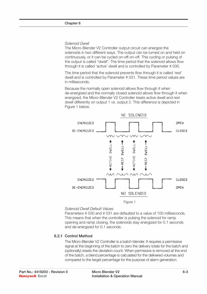
Part No.: 4418203 - Revision 0 Micro Blender V2 6-3 Installation & Operation Manual
Solenoid DwellThe Micro-Blender V2 Controller output circuit can energize the solenoids in two different ways. The output can be turned on and held on continuously, or it can be cycled on-off-on-off. This cycling or pulsing of the output is called “dwell”. The time period that the solenoid allows fl ow through it is called ‘active’ dwell and is controlled by Parameter # 030.
The time period that the solenoid prevents fl ow through it is called ‘rest’ dwell and is controlled by Parameter # 031. These time period values are in milliseconds.
Because the normally open solenoid allows fl ow through it when de-energized and the normally closed solenoid allows fl ow through it when energized, the Micro-Blender V2 Controller treats active dwell and rest dwell differently on output 1 vs. output 2. This difference is depicted in Figure 1 below.
Solenoid Dwell Default ValuesParameters # 030 and # 031 are defaulted to a value of 100 milliseconds. This means that when the controller is pulsing the solenoid for ramp opening and ramp closing, the solenoids stay energized for 0.1 seconds and de-energized for 0.1 seconds.
6.2.1 Control MethodThe Micro-Blender V2 Controller is a batch blender. It requires a permissive signal at the beginning of the batch to zero the delivery totals for the batch and (optionally) resets the deviation count. When permissive is removed at the end of the batch, a blend percentage is calculated for the delivered volumes and compared to the target percentage for the purpose of alarm generation.
Chapter 6
Figure 1
6-4 Micro Blender V2 Part No.: 4418203 - Revision 0 Installation & Operation Manual
Located on the lower left area of the display is the deviation count. This value is a positive or negative number that represents the error between the actual blend stream and wild stream volumes vs. a “perfect” blend. The count is in wild stream pulses. Negative counts mean that the blend stream is running behind target. Positive counts mean that the blend stream is ahead or too great.
Control valve action is based upon the magnitude and polarity of the error. Stated simply, if the count is negative, the blend control valve is opened. If the count is positive, it is closed. If the count falls very near zero, the control valve is locked in its present position.
A series of control windows must be set up in the Parameter settings. Each control window value establishes the outer limit in deviation count for that window. When the deviation count is inside that window, the controller reacts in a specifi c way when controlling the blend stream control valve. The deviation count value falling in a specifi c control window changes the active and rest solenoid dwell values used.
Parameter 020 - Inner Control Window LimitThe Inner Control Window Limit establishes a distance from zero in the error count. When the count value is less than this number, the control output from the controller is locked. No correction is made to the blend stream control valve. This value effectively establishes the “dead band” in which the error count can drift without correction. The dead band is plus or minus this value.
Parameter 021 - Second Control Window LimitThe Secondary Control Window Limit sets a distance from zero in the error count. This value should be greater than Parameter 020 and less than Parameter 022. When the count value is greater than the Parameter 020 value and less than this value, the controller uses one-half the active dwell (Parameter 030) value and double the rest dwell (Parameter 031) value when controlling the blend stream control valve.
Parameter 022 - Third Control Window LimitThe Third Control Window Limit sets a distance from zero in the error count. This value should be greater than Parameter 021 and less than Parameter 023. When the count value is greater than the Parameter 021 value and less than this value, the controller uses the active dwell (Parameter 030) value and the rest dwell (Parameter 031) value when controlling the blend stream control valve.
Parameter 023 - Outer Control Window LimitThe Outer Control Window Limit sets a distance from zero in the error count. This value should be greater than Parameter 022. When the count value is greater than the Parameter 022 value and less than this value, the controller uses double the active dwell (Parameter 030) value and one-half the rest dwell (Parameter 031) value when controlling the blend stream control valve.
Chapter 6
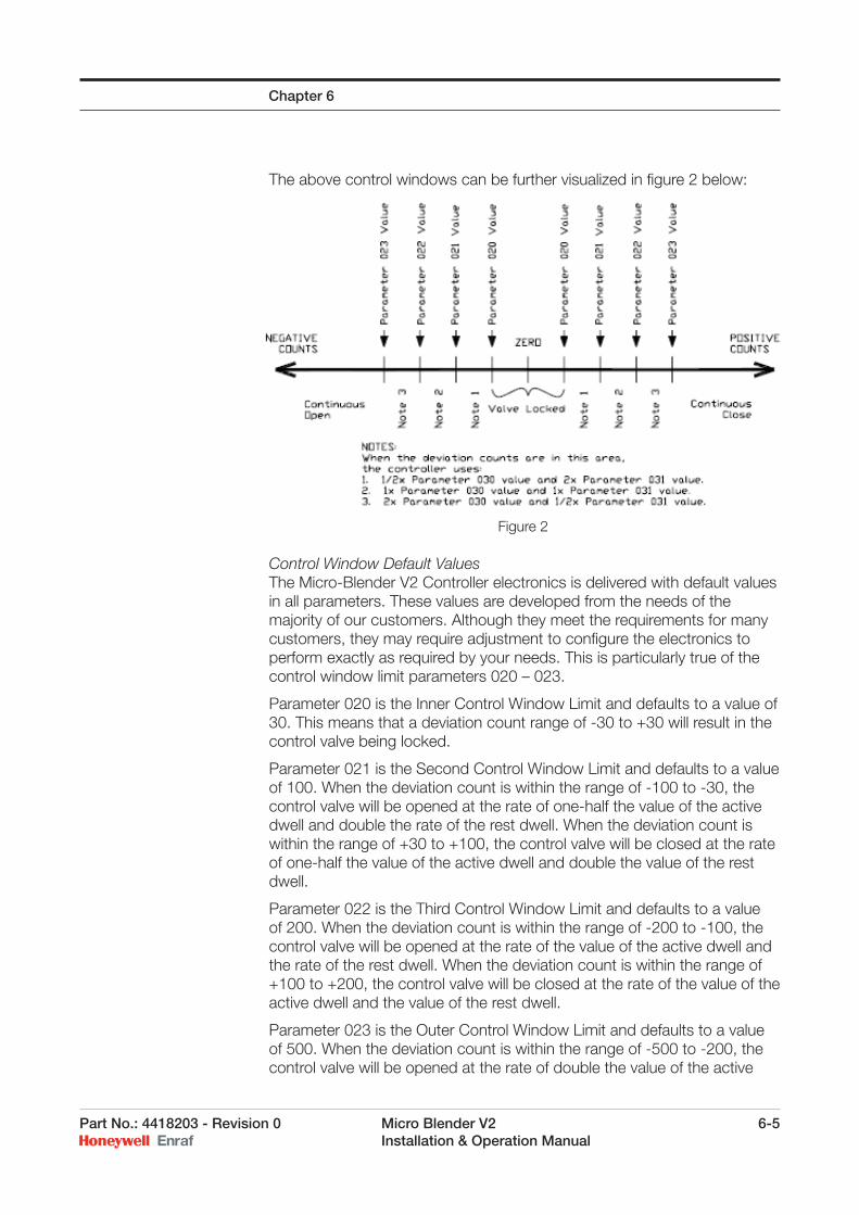
Part No.: 4418203 - Revision 0 Micro Blender V2 6-5 Installation & Operation Manual
The above control windows can be further visualized in fi gure 2 below:
Control Window Default ValuesThe Micro-Blender V2 Controller electronics is delivered with default values in all parameters. These values are developed from the needs of the majority of our customers. Although they meet the requirements for many customers, they may require adjustment to confi gure the electronics to perform exactly as required by your needs. This is particularly true of the control window limit parameters 020 – 023.
Parameter 020 is the Inner Control Window Limit and defaults to a value of 30. This means that a deviation count range of -30 to +30 will result in the control valve being locked.
Parameter 021 is the Second Control Window Limit and defaults to a value of 100. When the deviation count is within the range of -100 to -30, the control valve will be opened at the rate of one-half the value of the active dwell and double the rate of the rest dwell. When the deviation count is within the range of +30 to +100, the control valve will be closed at the rate of one-half the value of the active dwell and double the value of the rest dwell.
Parameter 022 is the Third Control Window Limit and defaults to a value of 200. When the deviation count is within the range of -200 to -100, the control valve will be opened at the rate of the value of the active dwell and the rate of the rest dwell. When the deviation count is within the range of +100 to +200, the control valve will be closed at the rate of the value of the active dwell and the value of the rest dwell.
Parameter 023 is the Outer Control Window Limit and defaults to a value of 500. When the deviation count is within the range of -500 to -200, the control valve will be opened at the rate of double the value of the active
Chapter 6
Figure 2
6-6 Micro Blender V2 Part No.: 4418203 - Revision 0 Installation & Operation Manual
dwell and one-half the rate of the rest dwell. When the deviation count is within the range of +200 to +500, the control valve will be closed at the rate of double the value of the active dwell and one-half the value of the rest dwell.
When the deviation count is less than -500, the control valve is sent a continuous open signal on Outputs 1 & 2. When the deviation count is greater than +500, the control valve is sent a continuous close signal. Additionally, during this time when the deviation count absolute value is greater than 500, the “Control Failure Alarm” is timing and will eventually cause an alarm condition if the count does not return inside the outer control window limits.
6.2.2 Control AdjustmentSet up of the Micro-Blender V2 Controller consists of adjusting the four control window limits, the two solenoid dwell times, and fi nally the two speed needle valves in the upstream and downstream legs of the solenoid streams.
Initial settingsIn addition to the previously mentioned default values for the controller parameters, the speed needle valves need to be set. With the blender idle, run each of the speed adjustment needle valves fully closed, then open them four complete turns. With these settings in place the blender will initially start and run although operation may be erratic.
Normal OperationWhen the blender is running normally, the deviation count will cycle above and below zero. It does this because of the digital nature of the valve control method. It will rarely hold near the zero deviation count. The objective when tuning the blender is to minimize the swings of the deviation counts, and keep the deviation count in the dead band established by the Inner Control Window Limit for as long as possible.
Many factors interact to determine the ideal tuning of the Micro-Blender V2 Controller electronics. For this reason, it is impossible to predict what the parameter and needle valve settings will ultimately be. These factors include the differential pressure across the blend control valve, the pressure of the wild stream, the type of control valve, etc. It is possible to observe the operation of the blender and optimize each of the settings accordingly. The following paragraphs explain this process.
Tuning Set upThe fi rst objective is to adjust the control window limits very wide in order to give room to observe the deviation count fl uctuations. Leave Parameter 020 set to 30 initially. Set Parameter 021 to 35 counts, 022 to 1250 counts, 023 to 1500 counts. This effectively forces the blender to use equal active and rest dwell during initial tuning steps. Turn off the Control Failure Alarm by setting Parameter 310 = 0.
Chapter 6
Part No.: 4418203 - Revision 0 Micro Blender V2 6-7 Installation & Operation Manual
Establish fl ow through the blender and allow the control valve to swing to its extremes several times, noting the plus and minus extreme counts. The count must change direction within 1250 counts. If it does not change direction within 1250 counts initially, widen the windows further.
Needle Valve Speed AdjustmentIf the deviation count consistently goes more positive than negative, slightly close the speed adjustment needle valve nearest the normally closed solenoid valve. (Downstream solenoid on a globe valve, pressure side of a hydraulically actuated valve.) Start out closing it by ½ turns until a noticeable change is effected, then smaller adjustments until the positive and negative deviation swings are equal.
If the deviation count consistently goes more negative than positive, slightly close the speed adjustment needle valve nearest the normally open solenoid valve. (Upstream solenoid on a globe valve, vent side of a hydraulically actuated valve.) Start out closing it by ½ turns until a noticeable change is effected, then smaller adjustments until the positive and negative deviation swings are equal.
The purpose of the adjustment above is to correct for variations in Cv or fl ow of fl uid through the two different solenoid valve types and to equalize the opening and closing times. Lock the speed adjustment needle valves in these positions.
Dwell AdjustmentSlowly increase BOTH Parameter 030 and 031 by increments of about 20 milliseconds while observing the deviation count swing extreme numbers. As the dwell value is increased, the peak value of the deviation count will decrease. At some point, the count swing will start back upward. The ideal setting for dwell is the point at which the deviation count swing is smallest.
Second Control Window Limit AdjustmentChange Parameter 021 from 35 to 1000 (higher if the swing is greater than this value). Allow the deviation count swing to stabilize positive and negative again and note the peak value. The setting for the Second Control Window Limit Parameter 021 should be one-half the peak deviation value. Thus, if the blender was swinging from -725 to +725, set Parameter 021 to 363.
Third Control Window Limit AdjustmentChange Parameter 022 from 1250 to 150% of Parameter 021. Thus if Parameter 021 was set to 363 in the step above, 150% of 363 = 545.
Outer Control Window Limit AdjustmentLastly, change the value in Parameter 023 from 1500 to 200% of Parameter 021. In our example, 021 = 363 times 200% = 726.
OptimizationThe blender is now set to control equally over its widest range of conditions. However, tuning may be improved upon if additional steps are taken. These steps take considerable fl ow observations and may not be practical unless repeated blending batches are undertaken.
Chapter 6
6-8 Micro Blender V2 Part No.: 4418203 - Revision 0 Installation & Operation Manual
In an attempt to minimize the swing of deviation counts, the following observations and adjustments can be made:
Note the extreme deviation count values. Reduce the value in Parameter 021 by 10% and then recalculate and set Parameters 022 and 023 by the 150% and 200% amounts previously used. Again observe the extreme deviation count values. Did the value decrease? If yes, then an improvement has been accomplished. This process can be repeated as needed. Take small steps when reducing the value in 021, keeping them 10% or smaller. Remember to recalculate and set the values for 022 and 023 each time. At some point the optimum setting will be passed and the extreme deviation count value will begin to increase again. The value in Parameter 021 should be increased back toward the previous setting.
Closely observe the counts during start up and shut down of the blender. If the deviation count is exceeding the value in Parameter 023 for more than a few seconds during this time, the value in this Parameter should be increased. The value in Parameter 311 should be double the number of seconds that the count remains above the value in Parameter 023.
Lastly, remember to turn on the Control Failure Alarm by setting Parameter 310 back to 2.
6.3 Calibrating the Micro-Blender V2
Calibration of the Micro-Blender V2 requires a calibrated container with a volume that is equal to or greater than the volume defi ned during the test procedure.
6.3.1 ProcedureThe Micro-Blender V2 may only be tested when no permissive is present. To confi gure the Micro-Blender V2 for the test mode enter the following steps:
1) With the Micro-Blender V2 in the idle state press the ATTN button on the HHC.
2) When the Micro-Blender V2 displays ENTER COMMAND, press the TEST button on the HHC.
3) If the Micro-Blender V2 asks for a password enter your password.
4) The Micro-Blender V2 will then display:
Enter Test Vol 00000
5) Adjust the Test Volume using the cursor keys on the HHC.
6) Press ENTER to store the adjusted test volume.
7) Pressing TEST again will start the proving procedure.
Chapter 6
Part No.: 4418203 - Revision 0 Micro Blender V2 6-9 Installation & Operation Manual
After the calibration process the display will refl ect the total volume of fuel that the Micro-Blender V2 Controller has determined was delivered. If during the testing procedure the calibrated container and the volume indicated on the Micro-Blender V2 Controller do not agree, then a change in the meter K-factor is required.
To have the Micro-Blender V2 automatically calibrate the meter factor for you, press the ENTER key after the test is complete and the Micro-Blender V2 display will change to:
Volume Del = 00110.02 (This is the number the Micro-Blender V2 thinks it delivered)
The Micro-Blender V2 displays the volume that it determined was delivered (00110.02 Gallons in this case); change the value to indicate the volume of fuel that was actually delivered into the calibrated container. When the correct volume in the calibrated container is indicated, press the ENTER key on the Hand-Held Controller and the Micro-Blender V2 will automatically calibrate and store a new meter factor. This method provides greater accuracy, since the meter factor is now calibrated to 3 decimal places, and removes the possibility of a math error by the operator.
WARNING! After changing any meter factor or any calibration amount, check for accuracy by repeating the calibration test.
6.3.2 K-Factors:The Micro-Blender V2 Controller™ must have the K-Factors for the Wild Stream and Blend Stream meters entered into it. Parameter 001 is the Wild Stream K-Factor and parameter 002 is the Blend Stream K-Factor. The K-Factors are in pulses per unit volume. The exact K-Factor of the source of the Wild Stream pulses must be known since the Micro-Blender V2 Controller provides no means to prove this meter. The Blend Stream meter will be determined during the Test Calibration exercise below. This is a proving means for the Blend Stream meter.
6.3.3 Test Calibration Procedure:The Micro-Blender V2 Controller provides the user with a means to prove the Blend Stream meter and determine the exact K-Factor for that meter. The Test Procedure involves running some volume through the Blend Stream meter. This volume is also metered by a calibrated reference, such as a prover can or master meter. The volume metered by the Blend Stream meter is then compared to the volume metered by the calibrated reference. A ratio of the two volumes is then applied to the Blend Stream K-Factor currently stored in the Micro-Blender V2 Controller to determine a new ‘calibrated’ K-Factor. This new meter factor is then stored and used as the new K-Factor for the Blend Stream meter.
Chapter 6
!
6-10 Micro Blender V2 Part No.: 4418203 - Revision 0 Installation & Operation Manual
6.3.4 Set-Up and Calibration:The Test mode of the Micro-Blender V2 Controller is a preset type of operation. The user has the ability to set the high fl ow rate and low fl ow rates of the test, the starting and stopping volumes for the low fl ow rate, and the fi nal valve closing volume. All of these values are defi ned by parameters 200 through 240. It must be noted that ALL parameters between 200 and 240 have absolutely no effect in any mode of operation other than TEST. The inner and outer fl ow control window allows the user to set the fl ow rate window around the larger fl ow rate where the Micro-Blender V2 Controller will not try to control the valve. For instance, if the high fl ow rate is set to be 100 units per minute, and the inner fl ow control window is set for 15, then so long as the measured fl ow rate of the Blend Stream is between 85 and 115 units per minute, the Blend Stream valve will remained locked in its current position. The low fl ow rate is provided to allow the user to ramp up to the high fl ow rate then ramp down without causing excessive line shock. The fl ow rates should be set to closely mimic the actual fl ow rates that will be run through the unit in normal operation. Once the user has set up the parameters 200 - 230, the unit is now ready to run a TEST.
To run a test, the user would hit the ATTN then TEST buttons on the Hand-Held Remote (HHR) provided with the unit. The user will be prompted for the volume to run through the meter for the test. Remember, this volume is the metered volume of the Blend Stream meter. The unit will control the Blend Stream to load this amount based on the K-Factor currently stored in the unit. If this K-Factor is fairly inaccurate, it is possible the unit will over fl ow the prover can on the fi rst test run. There must be a hand operated control valve in line with Blend Stream to shut the fl ow off in just such a case.
Once the user has entered a preset volume to load through the unit, the unit is ready to begin the test. After the user presses the TEST button to begin the test, the Micro-Blender V2 Controller will begin to control the Blend Stream to load the desired volume. If the user desires to stop the test for any reason, simple hit the ATTN then ESCAPE keys on the HHC. This will cause the Blend Stream valve to immediately begin to close.
It is also possible to operate the unit in the test mode and control the fl ow rate of the stream by using the above mentioned mandatory hand controlled valve. Simply set the high and low fl ow rates to some value higher than the steam will be controlled at and the preset volume to some value than the volume to be loaded. After fl ow is started by the Micro-Blender V2 Controller™, the user can throttle the stream with the hand valve, then hit the ATTN then ESCAPE buttons on the HHC to shut the Blend Stream Valve and get to the “VOLUME LOADED’ screen on the Micro-Blender V2 Controller.
It the Micro-Blender V2 Controller is allowed to control the fl ow rate, it will shut down fl ow at the completion of the preset volume. After the fl ow has completely stopped, the user will press the ATTN and then ENTER buttons to proceed to the “VOLUME LOADED” screen.
Chapter 6
Part No.: 4418203 - Revision 0 Micro Blender V2 6-11 Installation & Operation Manual
On the ‘VOLUME LOADED’ screen, the user enters the volume as measured on the calibration reference metering device. After pressing ENTER, the Micro-Blender V2 Controller will display the new K-Factor for the Blend-Stream and ask if it is to be sorted or not. After storing the value, one more test run should be to verify the accuracy of the K-Factor.
Chapter 6

6-12 Micro Blender V2 Part No.: 4418203 - Revision 0 Installation & Operation Manual
Chapter 6
Intentionally left blank.
Part No.: 4418203 - Revision 0 Micro Blender V2 7-1 Installation & Operation Manual
CHAPTER 7
7.1 Micro-Blender V2 Controller Display Setup
7.1.1 Idle Mode Display InformationThe Micro-Blender V2 Controller can be set to scroll through any one of three screens while un-permitted. The screens that the unit can scroll through are the Deviation/Blend Percentage screen, the Transaction Total Screen, and the Accumulative Totals Screen. The screens selected to be displayed are determined by the value in parameter 152 (see description of parameter 152 for details). Anytime the unit is permitted, the unit automatically locks on the Deviation/Blend Percentage screen. The scrolling resumes when the unit is again un-permitted.
The Micro-Blender V2 Controller gives the user the ability to temporarily stop the scrolling and lock the displays on any one of the three screens for a period of time determined by parameters 153 (in seconds). To stop the scrolling, the user would use the Hand-Held Remote and press the ATTN then either F1, F2, or F3. The F1 button will lock the unit on the Deviation/Blend Percentage screen; F2 will lock on the Accumulative Totals; and F3 will lock on the Transaction Totals. The user can lock on any screen using Function keys, regardless of whether or not the particular screen is selected by parameter 152 to be scrolled through. For example, say that the unit is set to display only the Deviation/Blend Percentage screen (parameter 152 = 1). The user has the ability, at any time, to lock the display to the Accumulative Totals screen by pressing ATTN, F2, or lock the Transaction Totals screen by pressing ATTN, F3.
7.1.2 Time & Temperature Confi rmationDuring operation or when idle, the current time and temperature can be determined by using the Hand-Held Remote. The user should press ATTN, and the TIME button. The display on the controller will change from the running screen to a custom screen. The current temperature is displayed on the upper line and the current time is displayed on the lower line. The user can press the ESC button to return to the running display, or if left alone, the controller will time out and return to the running display automatically.
7.1.3 Analog Valve Control Output DisplayWhen using the DC analog output as the control valve output, the user may occasionally need to view the output current and percentage being transmitted to the valve.
Using the Hand Held Controller, the user should press [ATTN] and “0” to display the analog control screen. The following lines are displayed: nn.n milliamps DIR (+) % (nnn)
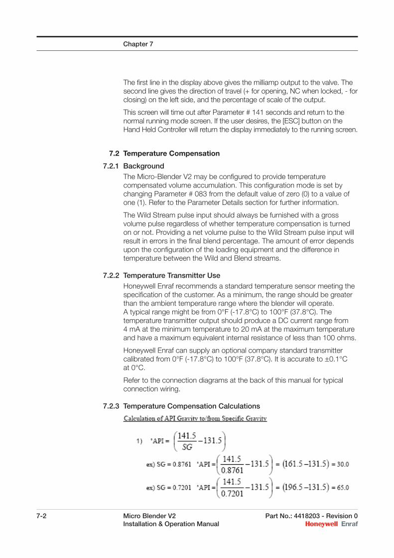
7-2 Micro Blender V2 Part No.: 4418203 - Revision 0 Installation & Operation Manual
The fi rst line in the display above gives the milliamp output to the valve. The second line gives the direction of travel (+ for opening, NC when locked, - for closing) on the left side, and the percentage of scale of the output.
This screen will time out after Parameter # 141 seconds and return to the normal running mode screen. If the user desires, the [ESC] button on the Hand Held Controller will return the display immediately to the running screen.
7.2 Temperature Compensation
7.2.1 BackgroundThe Micro-Blender V2 may be confi gured to provide temperature compensated volume accumulation. This confi guration mode is set by changing Parameter # 083 from the default value of zero (0) to a value of one (1). Refer to the Parameter Details section for further information.
The Wild Stream pulse input should always be furnished with a gross volume pulse regardless of whether temperature compensation is turned on or not. Providing a net volume pulse to the Wild Stream pulse input will result in errors in the fi nal blend percentage. The amount of error depends upon the confi guration of the loading equipment and the difference in temperature between the Wild and Blend streams.
7.2.2 Temperature Transmitter UseHoneywell Enraf recommends a standard temperature sensor meeting the specifi cation of the customer. As a minimum, the range should be greater than the ambient temperature range where the blender will operate. A typical range might be from 0°F (-17.8°C) to 100°F (37.8°C). The temperature transmitter output should produce a DC current range from 4 mA at the minimum temperature to 20 mA at the maximum temperature and have a maximum equivalent internal resistance of less than 100 ohms.
Honeywell Enraf can supply an optional company standard transmitter calibrated from 0°F (-17.8°C) to 100°F (37.8°C). It is accurate to +0.1°C at 0°C.
Refer to the connection diagrams at the back of this manual for typical connection wiring.
7.2.3 Temperature Compensation Calculations
Chapter 7
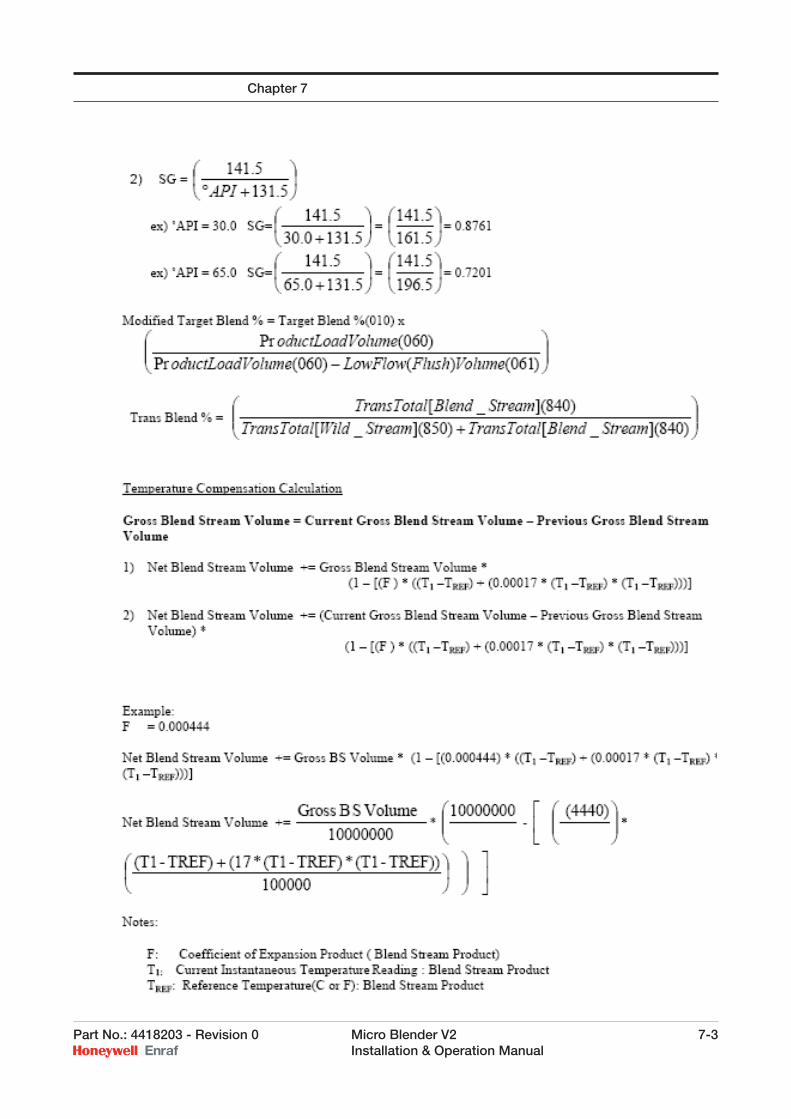
Part No.: 4418203 - Revision 0 Micro Blender V2 7-3 Installation & Operation Manual
Chapter 7
7-4 Micro Blender V2 Part No.: 4418203 - Revision 0 Installation & Operation Manual
7.3 Clean Start Operation
Clean Start is a term used in the fuel truck loading world to indicate the technique of ending the fuel transaction with the loading arm free of contaminating additives, blend product, etc. Thus the loading arm is “Clean” during the “Start” of the next transaction.
Blend chemical is typically injected upstream of the main product fl ow control valve and product fl ow meter. This is due to regulations by most states preventing injection of any fl uids downstream of the custody transfer meter. The net result is that blend chemical may be trapped in the loading arm, piping, meter, and control valve. In some cases this can be a signifi cant volume. The next truck compartment loaded from the arm will receive these chemicals. In the case of detergent additives, the effects are minimal. But in the case of ethanol or biodiesel, this trail-back of chemical into the next compartment or truck is detrimental.
The solution to trail-back of blended products is to stop blending early enough in the delivery to allow all of the blend stream chemical to be fl ushed into the truck compartment by the main or wild stream fl ow. In this way the loading arm is clean for the next delivery.
Stopping the blend fl ow prior to the wild stream stopping at the end of the delivery requires that the blender know several pieces of information in advance: The blender must know the compartment volume being loaded. This is
required to know how much blend stream volume is necessary to meet the recipe requirements.
The blender must know how much pipe volume there is between the point of injection of the blend stream into the wild stream and the end of the loading arm coupling. This is the minimum volume that must be fl ushed at the end of the load to ensure all of the blend is in the truck.
The blender also requires the target recipe or percentage of blend stream to the total volume delivered for the compartment.
Each of these pieces of information is needed prior to the start of the delivery. Although the recipe may be fi xed in many applications, it can vary from delivery to delivery. Compartment volumes certainly vary from truck to truck and even within the same truck. For this reason the Micro-Blender V2 typically requires full communications control with the terminal automation system in order to accurately perform Clean Start.
7.3.1 SETUPThe steps listed below should be followed to set up Clean Start in the Micro-Blender V2.
1. Calculate the volume of product in the piping, between the point of blend stream injection and the end of the loading arm coupling. Include any meter, control valve, strainer, or other equipment contained in that piping. Error on the high side.
Chapter 7
Part No.: 4418203 - Revision 0 Micro Blender V2 7-5 Installation & Operation Manual
2. Add 10% to that volume to ensure that all blend chemical is fl ushed into the truck.
3. Enter the volume calculated above into controller Parameter # 061.
4. Select the method of control for blend stop. Setting Parameter # 070 = 0 will allow the blender to stop blending when the permissive signal is removed. The blender then expects the volume in Parameter # 061 to fl ow, bringing the blend percentage down to the target percentage. Setting Parameter # 070 = 1 allows the blender to monitor the delivered volume and determine when to stop the blend, regardless of the state of the permissive signal.
7.3.2 USEAfter the driver has preset his compartment volume, the terminal automation system must download the volume to the Micro-Blender V2 Parameter # 060. If the blend percentage required changes, then it also must be downloaded to controller Parameter # 010. The automation system can then permit the blender for the transaction.
The blender will recalculate the target percentage to use during the delivery based upon blending into a reduced volume of wild stream component. This reduced volume amount is the preset volume minus the fl ush volume delivered at the end of the transaction.
The following mathematics are performed.
To determine a blend percentage for use during delivery, the controller calculates:
PLVMTB% = TB% X ------------- PLV - LFV
Where: MTB% = Modifi ed Target Blend Percentage TB% = Target Blend Percentage (Parameter # 010) PLV = Preset Volume (Parameter # 060)
To calculate what the transaction blend percentage was during the delivery, the controller calculates:
Trans Total(Blend Stream)Trans Blend % = -------------------------------------------------------------- Trans Total(Wild Stream) + Trans Total(Blend Stream)
Where: Trans Blend % = value to be stored in Parmeter # 850 Trans Total(Blend Stream) = value in Parameter # 840 Trans Total(Wild Stream) = value in Parmeter # 830
Chapter 7
7-6 Micro Blender V2 Part No.: 4418203 - Revision 0 Installation & Operation Manual
Chapter 7
Intentionally left blank.
Part No.: 4418203 - Revision 0 Micro Blender V2 8-1 Installation & Operation Manual
CHAPTER 8
8.1 Micro-Blender V2 Controller Communication Settings
Communication with the Micro-Blender V2 Controller may be achieved by two methods. The Hand-Held Controller (HHC) and its keypad access the Micro-Blender V2 Controller via an infrared port, through the explosion-proof enclosure window, in much the same manner as a television remote control. Use of the HHC offers the convenience and safety of on-site communications with the unit in a hazardous environment, without having to remove the cover and exposing potentially explosive electrical connections.
The other method of communications takes place through a hard-wired, serial communications port which supports EIA 485 standards, and is connected to the master via a data communications line.
Protocol selection is determined by setting Parameter # 190, with the options being:
Disable serial port (0)
Type I – FMC Smith (1)
Type II – Brooks (2)
Type III – Not currently used (3)
Type IV – Modbus RTU ASCII protocol (4)
Type V – Titan protocol (5)
Refer to the Communications Specifi cation for complete details regarding your specifi c protocol.
The Baud rate is selected using Parameter # 195. The baud rate options are as follows:
1200 (0)
2400 (1)
9600 (2)
19,200 (3)
All protocols and baud rates use the following port settings:
Data Bits 8
Stop Bit 1
Parity None
8-2 Micro Blender V2 Part No.: 4418203 - Revision 0 Installation & Operation Manual
8.1.1 Communications and Communication WiringThe Micro-Blender V2 Controller uses either the 2-wire or 4-wire EIA-485 standard for communications. A converter is required to enable communications with peripheral devices such as modems or personal computers which use the EIA-232 interface standard. Honeywell Enraf can provide an EIA-485 to EIA-232 converter if your application requires one.
Communications via modem requires a modem to be installed at each end of the communications link, and an appropriate converter (if required). The modem must be programmed to Auto Answer, and the cabling must be designed to provide auto-answer capabilities on the terminal end.
Although often overlooked, proper system wiring is critical to the reliable operation of serial communications interfaces. Improper wiring can cause high data error rates and reduce data throughput.
Although exact wiring requirements vary depending on the type of interface used, each of the following is important to the overall success of a communications system:
Cable lengths and types
Shielding
Twisted Pair Wiring
Using the recommended cable (Belden Cable 9841 for 2-wire, 9842 for 4-wire) an EIA 485 interface may support multiple devices (stations) over a maximum wire length of 3600 feet.
The communications cable shield conductor or drain wire should be terminated at the host end only. The shield should be joined serially at each controller drop to maintain electrical continuity over its entire length, and be fully insulated from ground or other electrical contact at each exposed connection. The shield should be taped off or insulated at the controller most remote from the master host. There is no termination of the communications cable shield at any controller. The shield termination at the master host should be made to one of the following connections based upon availability and are listed in the order of priority if more than one exists: Separate earth ground, DC power supply common, AC distribution ground.
EIA 485 interfaces are typically used in multi-drop confi gurations. The system wiring can become very complex. When installing a 2-wire cable for use with the Micro-Blender V2 Controller, receive and transmit share the same conductor pair. The wires must be a twisted pair. When installing a 4-wire cable, the receive signal uses one pair and the transmit signal uses the other pair. Each of these pairs are separately twisted.
Wiring for EIA 485 must be designed as a daisy chain, meaning a single run starts at the host and progresses from controller to controller until the most distant controller is reached. Cable stubs are permitted so long as they are 15 feet or less in length. A 2-wire conductor pair must be terminated with a single 100 ohm resistor only at the most distant end
Chapter 8
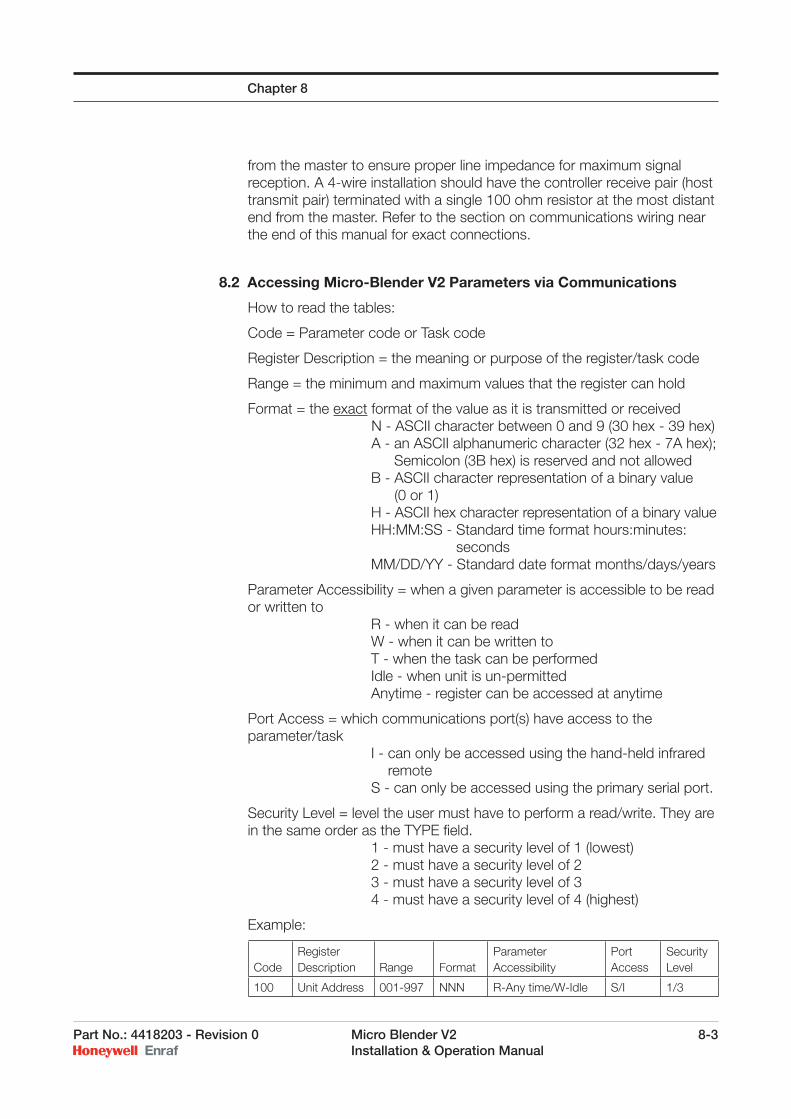
Part No.: 4418203 - Revision 0 Micro Blender V2 8-3 Installation & Operation Manual
from the master to ensure proper line impedance for maximum signal reception. A 4-wire installation should have the controller receive pair (host transmit pair) terminated with a single 100 ohm resistor at the most distant end from the master. Refer to the section on communications wiring near the end of this manual for exact connections.
8.2 Accessing Micro-Blender V2 Parameters via Communications
How to read the tables:
Code = Parameter code or Task code
Register Description = the meaning or purpose of the register/task code
Range = the minimum and maximum values that the register can hold
Format = the exact format of the value as it is transmitted or receivedN - ASCII character between 0 and 9 (30 hex - 39 hex)A - an ASCII alphanumeric character (32 hex - 7A hex);
Semicolon (3B hex) is reserved and not allowed B - ASCII character representation of a binary value
(0 or 1) H - ASCII hex character representation of a binary value HH:MM:SS - Standard time format hours:minutes:
seconds MM/DD/YY - Standard date format months/days/years
Parameter Accessibility = when a given parameter is accessible to be read or written to R - when it can be read W - when it can be written to T - when the task can be performed Idle - when unit is un-permitted Anytime - register can be accessed at anytime
Port Access = which communications port(s) have access to the parameter/task I - can only be accessed using the hand-held infrared
remote S - can only be accessed using the primary serial port.
Security Level = level the user must have to perform a read/write. They are in the same order as the TYPE fi eld. 1 - must have a security level of 1 (lowest) 2 - must have a security level of 2 3 - must have a security level of 3 4 - must have a security level of 4 (highest)
Example:
CodeRegister Description Range Format
Parameter Accessibility
Port Access
Security Level
100 Unit Address 001-997 NNN R-Any time/W-Idle S/I 1/3
Chapter 8
8-4 Micro Blender V2 Part No.: 4418203 - Revision 0 Installation & Operation Manual
The Parameter Code for this register is 100 and is identifi ed as the Unit Address. The value anywhere from 1 to 997. The format of the value, when transmitted or received, must be three digits. The register can be read any time, but can only be changed in the unpermitted mode. The parameter can be accessed using either the infrared remote or the serial port and applies to any mode of operation. In order to read the register value, the user must have a level 1 security level, but must have a level 3 to change the parameter.
8.3 Retrieving Archived Transaction Records
The Transaction Archive consists of 200 record storage locations. When the transaction fi le is initially cleared, all locations are empty. As each transaction is completed, it is stored sequentially into a record location. If 200 transactions are completed prior to them being read, the controller continues to save the transaction information by writing over the oldest record each time. Thus, the controller always has the most recent 200 transactions available.
Two methods exist for the retrieval of the transaction record data. The fi rst method is generally used as an on-going automatic process similar to that used by automation control computer systems. The second method is more commonly used occasionally by the user to dump the data to a portable laptop computer.
8.3.1 Automated Retrieval ProcessA pointer keeps track of the location of the oldest transaction, in this case record 000. Another pointer keeps track of the newest transaction record location. If ten transactions were created, the newest record pointer would point to record location 009 (don’t forget that a record is stored at location 000 also). The current transaction record would be record number 010.
The fi rst step in reading the Transaction records from the fi le is to reset the pointer. The [index] pointer should be reset using Task 911. This moves the read [index] to the Latest Transaction Record location.
The total number of transaction records in use is kept in Parameter 900. This value may be read by a host computer to determine the total number of records needing to be retrieved from the Micro-Blender V2 controller. A program loop should be set up to perform a “read” of a transaction record. The loop should execute (Parameter 900 value) times.
Perform a read from Parameter 902. This brings the data into the host from position [index] in the fi le.
Move the pointer back one record by executing a Task 912.
Repeat the read from Parameter 902.
Repeat these two steps for Parameter 900 times.
Chapter 8
Part No.: 4418203 - Revision 0 Micro Blender V2 8-5 Installation & Operation Manual
At the end of this sequence, execute a Task 900 to move the current record pointer to the head of the fi le. This ensures that the next read cycle does not read previously read data, and ensures the most room available in the fi le.
8.3.2 Bulk Retrieval ProcessWhen the user executes a TASK 913, either with the Hand-Held IR Controller or through communications, the controller immediately transmits all records, starting with the oldest. The controller continues to send records until the newest record is sent. The transmission then ends. There is no hand-shaking with the serial port so the receiving computer must be able to keep up with the transmission rate.
It is the user’s responsibility to ensure the data is received properly and stored. At this point if a TASK 913 is executed again, the exact same data will be sent. A TASK 913 is therefore non-destructive.
With the successful capture of the transaction data, the user should execute a TASK 900 to move the current record pointer to the head of the fi le. This ensures that the next read cycle does not read previously read data, and ensures the most room available in the fi le. Note that a TASK 900 is destructive, meaning that old transaction data will be lost, so the user should ensure it has been captured prior to execution.
8.3.3 Transaction Record FormatThe transaction record is formatted and transmitted in the following order:
Date MM/DD/YY1,Time HH:MM:SS,Transaction Number NNN,Average Temperature NNN.N,Blend Percentage NNN.N,Wild Stream Total Volume NNNNNN.NN,Gr Blend Stream Total Volume NNNNNN.NN,Net Blend Stream Total NNNNNN.NN,Transaction Alarms HHHH (hex)
Information stored in the transaction record is sent to an external computer in the form of ASCII text. A “fi eld” is one item of data in a record. A “record” is one blending transaction. The “fi le” refers to all records stored.
Data is transmitted as comma delimited fi elds, with individual records ending in a carriage return, line feed sequence. There are no headers or footers. There are no structure characters such as tabs or spaces transmitted. When the user selects Task # 913, transmission begins immediately and proceeds until all records are sent. There is no hardware or software handshaking between the blender and the external computer.
NOTES:
1) Date format is dependant upon the setting of Parameter # 109.
Chapter 8

8-6 Micro Blender V2 Part No.: 4418203 - Revision 0 Installation & Operation Manual
Chapter 8
Intentionally left blank.
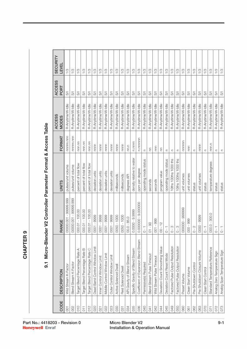
Part No.: 4418203 - Revision 0 Micro Blender V2 9-1 Installation & Operation Manual
9.
1 M
icro
-Ble
nder
V2
Co
ntro
ller
Par
amet
er F
orm
at &
Acc
ess
Tab
le
CO
DE
DE
SC
RIP
TIO
NR
AN
GE
UN
ITS
FO
RM
AT
AC
CE
SS
M
OD
ES
AC
CE
SS
P
OR
T
SE
CU
RIT
Y
LEV
EL
001
Wild
Str
eam
K-F
acto
r00
000.
001
- 99
999.
999
puls
es/u
nit v
olum
enn
nnn.
nnn
R-A
nytim
e/W
-Idl
eS
/I1/
3
002
Ble
nd S
trea
m K
-Fac
tor
0000
0.00
1 -
9999
9.99
9pu
lses
/uni
t vol
ume
nnnn
n.nn
nR
-Any
time/
W-I
dle
S/I
1/3
010
Targ
et B
lend
Per
cent
age
Rat
e A
000.
01 -
100
.00
perc
ent o
f tot
al fl
ownn
n.nn
R-A
nytim
e/W
-Idl
eS
/I1/
3
011
Targ
et B
lend
Per
cent
age
Rat
e B
000.
01 -
100
.00
perc
ent o
f tot
al fl
ownn
n.nn
R-A
nytim
e/W
-Idl
eS
/I1/
3
012
Targ
et B
lend
Per
cent
age
Rat
e C
000.
01 -
100
.00
perc
ent o
f tot
al fl
ownn
n.nn
R-A
nytim
e/W
-Idl
eS
/I1/
3
020
Dea
d B
and
Con
trol
Win
dow
Lim
it00
01 -
999
9de
viat
ion
units
nnnn
R-A
nytim
e/W
-Idl
eS
/I1/
3
021
Inne
r C
ontr
ol W
indo
w L
imit
0001
- 9
999
devi
atio
n un
itsnn
nnR
-Any
time/
W-I
dle
S/I
1/3
022
Mid
dle
Con
trol
Win
dow
Lim
it00
01 -
999
9de
viat
ion
units
nnnn
R-A
nytim
e/W
-Idl
eS
/I1/
3
023
Out
er C
ontr
ol W
indo
w L
imit
0001
- 9
999
devi
atio
n un
itsnn
nnR
-Any
time/
W-I
dle
S/I
1/3
030
Act
ive
Sol
enoi
d D
wel
l00
50 -
100
0m
illise
cond
snn
nnR
-Any
time/
W-I
dle
S/I
1/3
031
Res
t Sol
enoi
d D
wel
l00
50 -
100
0m
illise
cond
snn
nnR
-Any
time/
W-I
dle
S/I
1/3
034
AP
I Gra
vity
of B
lend
Str
eam
00.0
- 8
5.0
degr
ees
AP
Inn
.nR
-Any
time/
W-I
dle
S/I
1/3
035
Spe
cifi c
Gra
vity
of B
lend
Str
eam
0.00
00 -
9.9
999
dens
ity re
lativ
e to
wat
ern.
nnnn
R-A
nytim
e/W
-Idl
eS
/I1/
3
036
Coe
ffi ci
ent o
f Exp
ansi
on B
lend
Str
eam
0.00
0000
- 9
.000
000
ppm
per
deg
ree
n.nn
nnnn
R-A
nytim
e/W
-Idl
eS
/I1/
3
040
Per
mis
sive
(s) R
equi
red
0 -
1op
erat
ing
mod
e st
atus
nR
-Any
time/
W-I
dle
S/I
1/3
041
Ble
nd S
trea
m P
ulse
Tim
eout
01 -
90
seco
nds
nnR
-Any
time/
W-I
dle
S/I
1/3
042
Wild
Str
eam
Pul
se T
imeo
ut00
1 -
999
seco
nds
nnn
R-A
nytim
e/W
-Idl
eS
/I1/
3
044
Dev
iatio
n C
ount
Sm
ooth
ing
Valu
e00
- 1
2pr
ogra
m v
alue
nnR
-Any
time/
W-I
dle
S/I
1/3
045
Dev
iatio
n C
ount
Res
et M
ode
0 -
1op
erat
ing
mod
e st
atus
nR
-Any
time/
W-I
dle
S/I
1/3
049
Fact
ored
Pul
se O
utpu
t Res
olut
ion
0 -
310
ths
100t
hs 1
000
ths
nR
-Any
time/
W-I
dle
S/I
1/3
050
Fact
ored
Pul
se O
utpu
t Res
olut
ion
0 -
310
ths
100t
hs 1
000
ths
nR
-Any
time/
W-I
dle
S/I
1/3
060
Pre
set V
olum
e00
0000
- 9
9999
9un
it vo
lum
esnn
nnnn
R-A
nytim
e/W
-Idl
eS
/I1/
3
061
Cle
an S
tart
Vol
ume
000
- 99
9un
it vo
lum
esnn
nR
-Any
time/
W-I
dle
S/I
1/3
062
Pre
-Shu
tdow
n C
ontr
ol0
- 2
stat
usn
R-A
nytim
e/W
-Idl
eS
/I1/
3
063
Pre
-Shu
tdow
n C
losu
re V
olum
e00
00 -
999
9un
it vo
lum
esnn
nnR
-Any
time/
W-I
dle
S/I
1/3
070
Cle
an S
tart
Con
trol
0 -
1st
atus
nR
-Any
time/
W-I
dle
S/I
1/3
071
Sta
ndar
d Te
mpe
ratu
re R
efer
ence
000.
0 -
300.
0te
mpe
ratu
re d
egre
esnn
n.n
R-A
nytim
e/W
-Idl
eS
/I1/
3
072
Ana
log
Zero
Tem
pera
ture
Sig
n0
- 1
stat
usn
R-A
nytim
e/W
-Idl
eS
/I1/
3
073
Ana
log
Spa
n Te
mpe
ratu
re S
ign
0 -
1st
atus
nR
-Any
time/
W-I
dle
S/I
1/3
C
HA
PT
ER
9
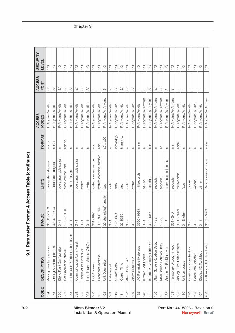
9-2 Micro Blender V2 Part No.: 4418203 - Revision 0 Installation & Operation Manual
CO
DE
DE
SC
RIP
TIO
NR
AN
GE
UN
ITS
FO
RM
ATA
CC
ES
S
MO
DE
SA
CC
ES
S
PO
RT
SE
CU
RIT
Y
LEV
EL
074
Ana
log
Zero
Tem
pera
ture
000.
0 -
200.
0te
mpe
ratu
re d
egre
esnn
n.n
R-A
nytim
e/W
-Idl
eS
/I1/
3
075
Ana
log
Spa
n Te
mpe
ratu
re00
0.0
- 20
0.0
tem
pera
ture
deg
rees
nnn.
nR
-Any
time/
W-I
dle
S/I
1/3
080
Ble
nd P
oint
Con
fi gur
atio
n0
- 1
oper
atin
g m
ode
stat
usn
R-A
nytim
e/W
-Idl
eS
/I1/
3
082
Net
Cal
cula
tion
Inte
rval
1.00
- 1
0.00
gros
s vo
lum
e un
itsnn
n.nn
R-A
nytim
e/W
-Idl
eS
/I1/
3
083
Tem
pera
ture
Com
pens
atio
n of
f/on
0 -
1st
atus
- o
ff/on
nR
-Any
time/
W-I
dle
S/I
1/3
084
Com
mun
icat
ion
Ala
rm R
eset
0 -
1op
erat
ing
mod
e st
atus
nR
-Any
time/
W-I
dle
S/I
1/3
085
Tem
pera
ture
Uni
ts °
F/°C
0 -
1sw
itch
nR
-Any
time/
W-I
dle
S/I
1/3
093
Long
Infra
red
Acc
ess
Off/
On
0 -
1sw
itch
nR
-Any
time/
W-I
dle
S/I
1/3
100
Uni
t Add
ress
001
- 99
7sy
stem
uni
que
num
ber
nnn
R-A
nytim
e/W
-Idl
eI
1/3
101
Bro
adca
st A
ddre
ss00
0, 9
98, 9
99sy
stem
com
mon
num
ber
nnn
R-A
nytim
e/W
-Idl
eI
1/3
102
Uni
t Des
crip
tion
20 c
har
alph
a/nu
mer
icte
xta0
.. a
20R
-Any
time/
W-A
nytim
eS
1/3
109
Dat
e Fo
rmat
0 -
1sw
itch
nR
-Any
time/
W-I
dle
S/I
1/3
110
Cur
rent
Dat
e12
/31/
99da
tem
m/d
d/yy
R-A
nytim
e/W
-Idl
eS
/I1/
3
111
Cur
rent
Tim
e23
:59:
59tim
ehh
:mm
:ss
R-A
nytim
e/W
-Idl
eS
/I1/
3
128
Ala
rm O
utpu
t # 1
0 -
2sw
itch
nR
-Any
time/
W-I
dle
S/I
1/3
129
Ala
rm O
utpu
t # 2
0 -
2sw
itch
nR
-Any
time/
W-I
dle
S/I
1/3
132
AC
Per
mis
sive
Hys
tere
sis
0000
- 9
999
milli
seco
nds
nnnn
R-A
nytim
e/W
-Idl
eI
1/3
140
Infra
red
Por
t Ena
ble
0 -
1of
f - o
nn
R-A
nytim
e/W
-Any
time
S1/
3
141
Infra
red
No
Act
ivity
Tim
e O
ut01
0 -
999
seco
nds
nnn
R-A
nytim
e/W
-Any
time
S/I
1/3
150
Ala
rm S
cree
n R
otat
ion
Del
ay1
- 99
seco
nds
nnR
-Any
time/
W-A
nytim
eS
/I1/
3
151
Mai
n S
cree
n R
otat
ion
Del
ay1
- 99
seco
nds
nnR
-Any
time/
W-A
nytim
eS
/I1/
3
152
Scr
eens
To
Be
Dis
play
ed1
- 7
oper
atin
g m
ode
stat
usn
R-A
nytim
e/W
-Any
time
S1/
3
153
Tem
pora
ry D
ispl
ay T
imeo
ut00
1 -
240
seco
nds
nnn
R-A
nytim
e/W
-Any
time
S1/
3
165
Ana
log
Out
put S
tep
Inte
rval
0000
- 9
999
milli
seco
nds
nnnn
R-A
nytim
e/W
-Idl
eI
1/3
180
Uni
t Lan
guag
e 0
- E
nglis
hfi x
edn
R-A
nytim
e/W
-Idl
eI
1/3
190
Com
mun
icat
ions
Pro
toco
l0
- 5
vario
usn
R-A
nytim
e/W
-Idl
eI
1/3
195
Bau
d R
ate
Sel
ecto
r0
- 3
vario
usn
R-A
nytim
e/W
-Idl
eI
1/3
197
Dis
play
I/O
Tes
t Mod
e0
- 1
off -
on
nR
-Any
time/
W-I
dle
I1/
3
200
Cal
ibra
tion
Hig
h Fl
ow R
ate
0001
- 9
999
Ble
nd v
olum
es/m
inut
enn
nnR
-Any
time/
W-A
nytim
eI
1/3
9.
1 P
aram
eter
Fo
rmat
& A
cces
s Ta
ble
(co
ntin
ued
) Chapter 9
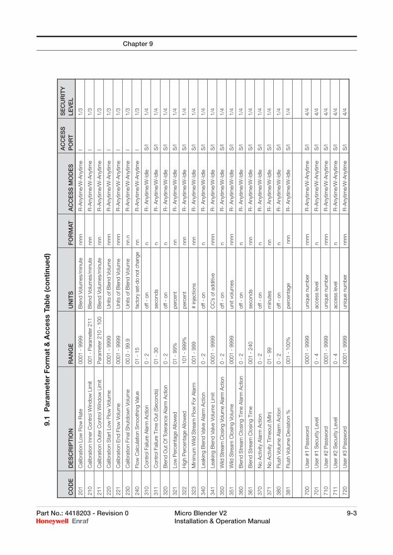
Part No.: 4418203 - Revision 0 Micro Blender V2 9-3 Installation & Operation Manual
Chapter 9
CO
DE
DE
SC
RIP
TIO
NR
AN
GE
UN
ITS
FO
RM
ATA
CC
ES
S M
OD
ES
AC
CE
SS
P
OR
TS
EC
UR
ITY
LE
VE
L
201
Cal
ibra
tion
Low
Flo
w R
ate
0001
- 9
999
Ble
nd V
olum
es/m
inut
enn
nnR
-Any
time/
W-A
nytim
eI
1/3
210
Cal
ibra
tion
Inne
r C
ontr
ol W
indo
w L
imit
001
- P
aram
eter
211
Ble
nd V
olum
es/m
inut
enn
nR
-Any
time/
W-A
nytim
eI
1/3
211
Cal
ibra
tion
Out
er C
ontr
ol W
indo
w L
imit
Par
amet
er 2
10 -
100
Ble
nd V
olum
es/m
inut
enn
nR
-Any
time/
W-A
nytim
eI
1/3
220
Cal
ibra
tion
Sta
rt L
ow F
low
Vol
ume
0001
- 9
999
Uni
ts o
f Ble
nd V
olum
enn
nnR
-Any
time/
W-A
nytim
eI
1/3
221
Cal
ibra
tion
End
Flo
w V
olum
e00
01 -
999
9 U
nits
of B
lend
Vol
ume
nnnn
R-A
nytim
e/W
-Any
time
I1/
3
230
Cal
ibra
tion
Fina
l Shu
tdow
n Vo
lum
e00
.0 -
99.
9U
nits
of B
lend
Vol
ume
nn.n
R-A
nytim
e/W
-Any
time
I1/
3
240
Flow
Cal
cula
tion
Sm
ooth
ing
Valu
e01
- 1
5fa
ctor
y se
t-do
not
cha
nge
nnR
-Any
time/
W-A
nytim
eI
1/3
310
Con
trol
Fai
lure
Ala
rm A
ctio
n0
- 2
off -
on
nR
- A
nytim
e/W
-Idl
eS
/I1/
4
311
Con
trol
Fai
lure
Tim
e O
ut (S
econ
ds)
01 -
30
seco
nds
nR
- A
nytim
e/W
-Idl
eS
/I1/
4
320
Ble
nd O
ut O
f Tol
eran
ce A
larm
Act
ion
0 -
2of
f - o
nn
R-
Any
time/
W-I
dle
S/I
1/4
321
Low
Per
cent
age
Allo
wed
01 -
99%
perc
ent
nnR
- A
nytim
e/W
-Idl
eS
/I1/
4
322
Hig
h P
erce
ntag
e A
llow
ed10
1 -
999%
perc
ent
nnn
R-
Any
time/
W-I
dle
S/I
1/4
323
Min
imum
Wild
Str
eam
Flo
w F
or A
larm
001
- 99
9#
inje
ctio
nsnn
nR
- A
nytim
e/W
-Idl
eS
/I1/
4
340
Leak
ing
Ble
nd V
alve
Ala
rm A
ctio
n0
- 2
off -
on
nR
- A
nytim
e/W
-Idl
eS
/I1/
4
341
Leak
ing
Ble
nd V
alve
Vol
ume
Lim
it00
01 -
999
9C
C’s
of a
dditi
venn
nnR
- A
nytim
e/W
-Idl
eS
/I1/
4
350
Wild
Stre
am C
losi
ng V
olum
e A
larm
Act
ion
0 -
2of
f - o
nn
R-
Any
time/
W-I
dle
S/I
1/4
351
Wild
Str
eam
Clo
sing
Vol
ume
0001
- 9
999
unit
volu
mes
nnnn
R-
Any
time/
W-I
dle
S/I
1/4
360
Ble
nd S
trea
m C
losi
ng T
ime
Ala
rm A
ctio
n0
- 2
off -
on
nR
- A
nytim
e/W
-Idl
eS
/I1/
4
361
Ble
nd S
trea
m C
losi
ng T
ime
001
- 24
0se
cond
snn
nR
- A
nytim
e/W
-Idl
eS
/I1/
4
370
No
Act
ivity
Ala
rm A
ctio
n0
- 2
off -
on
nR
- A
nytim
e/W
-Idl
eS
/I1/
4
371
No
Act
ivity
Tim
eout
(Min
)01
- 9
9m
inut
esnn
R-
Any
time/
W-I
dle
S/I
1/4
380
Flus
h Vo
lum
e A
larm
Act
ion
0 -
2of
f - o
nn
R-
Any
time/
W-I
dle
S/I
1/4
381
Flus
h Vo
lum
e D
evia
tion
%00
1 -
100%
perc
enta
ge n
nnR
- A
nytim
e/W
-Idl
eS
/I1/
4
700
Use
r #1
Pas
swor
d00
01 -
999
9un
ique
num
ber
nnnn
R-A
nytim
e/W
-Any
time
S/I
4/4
701
Use
r #1
Sec
urity
Lev
el0
- 4
acce
ss le
vel
nR
-Any
time/
W-A
nytim
e S
/I4/
4
710
Use
r #2
Pas
swor
d00
01 -
999
9un
ique
num
ber
nnnn
R-A
nytim
e/W
-Any
time
S/I
4/4
711
Use
r #2
Sec
urity
Lev
el0
- 4
acce
ss le
vel
nR
-Any
time/
W-A
nytim
eS
/I4/
4
720
Use
r #3
Pas
swor
d00
01 -
999
9un
ique
num
ber
nnnn
R-A
nytim
e/W
-Any
time
S/I
4/4
9.
1 P
aram
eter
Fo
rmat
& A
cces
s Ta
ble
(co
ntin
ued
)
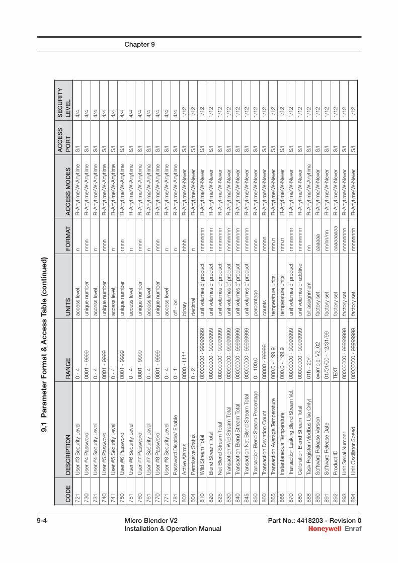
9-4 Micro Blender V2 Part No.: 4418203 - Revision 0 Installation & Operation Manual
Chapter 9
CO
DE
DE
SC
RIP
TIO
NR
AN
GE
UN
ITS
FO
RM
ATA
CC
ES
S M
OD
ES
AC
CE
SS
P
OR
TS
EC
UR
ITY
LE
VE
L
721
Use
r #3
Sec
urity
Lev
el0
- 4
acce
ss le
vel
nR
-Any
time/
W-A
nytim
eS
/I4/
4
730
Use
r #4
Pas
swor
d00
01 -
999
9un
ique
num
ber
nnnn
R-A
nytim
e/W
-Any
time
S/I
4/4
731
Use
r #4
Sec
urity
Lev
el0
- 4
acce
ss le
vel
nR
-Any
time/
W-A
nytim
eS
/I4/
4
740
Use
r #5
Pas
swor
d00
01 -
999
9un
ique
num
ber
nnnn
R-A
nytim
e/W
-Any
time
S/I
4/4
741
Use
r #5
Sec
urity
Lev
el0
- 4
acce
ss le
vel
nR
-Any
time/
W-A
nytim
eS
/I4/
4
750
Use
r #6
Pas
swor
d00
01 -
999
9un
ique
num
ber
nnnn
R-A
nytim
e/W
-Any
time
S/I
4/4
751
Use
r #6
Sec
urity
Lev
el0
- 4
acce
ss le
vel
nR
-Any
time/
W-A
nytim
eS
/I4/
4
760
Use
r #7
Pas
swor
d00
01 -
999
9un
ique
num
ber
nnnn
R-A
nytim
e/W
-Any
time
S/I
4/4
761
Use
r #7
Sec
urity
Lev
el0
- 4
acce
ss le
vel
nR
-Any
time/
W-A
nytim
eS
/I4/
4
770
Use
r #8
Pas
swor
d00
01 -
999
9un
ique
num
ber
nnnn
R-A
nytim
e/W
-Any
time
S/I
4/4
771
Use
r #8
Sec
urity
Lev
el0
- 4
acce
ss le
vel
nR
-Any
time/
W-A
nytim
eS
/I4/
4
781
Pas
swor
d D
isab
le/
Ena
ble
0 -
1of
f - o
nn
R-A
nytim
e/W
-Any
time
S/I
4/4
802
Act
ive
Ala
rms
0000
- f
f f f
bina
ryhh
hhR
-Any
time/
W-N
ever
S/I
1/12
804
Per
mis
sive
Sta
tus
0 -
2de
cim
aln
R-A
nytim
e/W
-Nev
erS
/I1/
12
810
Wild
Str
eam
Tot
al00
0000
00 -
999
9999
9un
it vo
lum
es o
f pro
duct
nnnn
nnnn
R-A
nytim
e/W
-Nev
erS
/I1/
12
820
Ble
nd S
trea
m T
otal
0000
0000
- 9
9999
999
unit
volu
mes
of p
rodu
ctnn
nnnn
nnR
-Any
time/
W-N
ever
S/I
1/12
825
Net
Ble
nd S
trea
m T
otal
0000
0000
- 9
9999
999
unit
volu
mes
of p
rodu
ctnn
nnnn
nnR
-Any
time/
W-N
ever
S/I
1/12
830
Tran
sact
ion
Wild
Str
eam
Tot
al00
0000
00 -
999
9999
9un
it vo
lum
es o
f pro
duct
nnnn
nnnn
R-A
nytim
e/W
-Nev
erS
/I1/
12
840
Tran
sact
ion
Ble
nd S
trea
m T
otal
0000
0000
- 9
9999
999
unit
volu
mes
of p
rodu
ctnn
nnnn
nnR
-Any
time/
W-N
ever
S/I
1/12
845
Tran
sact
ion
Net
Ble
nd S
trea
m T
otal
0000
0000
- 9
9999
999
unit
volu
mes
of p
rodu
ctnn
nnnn
nnR
-Any
time/
W-N
ever
S/I
1/12
850
Tran
sact
ion
Ble
nd S
tream
Per
cent
age
0 -
100.
0pe
rcen
tage
nnnn
R-A
nytim
e/W
-Nev
erS
/I1/
12
860
Tran
sact
ion
Dev
iatio
n C
ount
0000
0 -
9999
9co
unts
nnnn
nR
-Any
time/
W-N
ever
S/I
1/12
865
Tran
sact
ion
Ave
rage
Tem
pera
ture
000.
0 -
199.
9te
mpe
ratu
re u
nits
nnn.
nR
-Any
time/
W-N
ever
S/I
1/12
866
Inst
anta
neou
s Te
mpe
ratu
re00
0.0
- 19
9.9
tem
pera
ture
uni
tsnn
n.n
R-A
nytim
e/W
-Nev
erS
/I1/
12
870
Tran
sact
ion
Leak
ing
Ble
nd S
tream
Vol
.00
0000
00 -
999
9999
9un
it vo
lum
es o
f pro
duct
nnnn
nnnn
R-A
nytim
e/W
-Nev
erS
/I1/
12
880
Cal
ibra
tion
Ble
nd S
trea
m T
otal
00
0000
00 -
999
9999
9un
it vo
lum
es o
f add
itive
nnnn
nnnn
R-A
nytim
e/W
-Nev
erS
/I1/
12
888
Task
Reg
iste
r (M
odbu
s U
se O
nly)
01h
- 20
hbi
t ass
ignm
ent
nnR
-Any
time/
W-A
nytim
eS
/I1/
12
890
Sof
twar
e R
elea
se V
ersi
onex
ampl
e: V
2_02
fact
ory
set
aaaa
aaR
-Any
time/
W-N
ever
S/I
1/12
891
Sof
twar
e R
elea
se D
ate
01/0
1/00
- 1
2/31
/99
fact
ory
set
nn/n
n/nn
R-A
nytim
e/W
-Nev
erS
/I1/
12
892
Pro
duct
IDTE
XTfa
ctor
y se
taa
aaaa
aaa
R-A
nytim
e/W
-Nev
erS
/I1/
12
893
Uni
t Ser
ial N
umbe
r00
0000
00 -
999
9999
9fa
ctor
y se
tnn
nnnn
nnR
-Any
time/
W-N
ever
S/I
1/12
894
Uni
t Osc
illato
r S
peed
0000
0000
- 9
9999
999
fact
ory
set
nnnn
nnnn
R-A
nytim
e/W
-Nev
erS
/I1/
12
9.
1 P
aram
eter
Fo
rmat
& A
cces
s Ta
ble
(co
ntin
ued
)
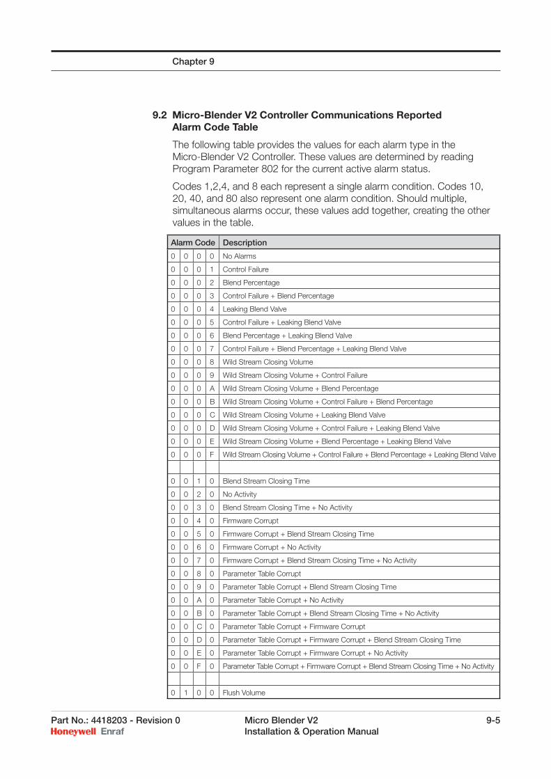
Part No.: 4418203 - Revision 0 Micro Blender V2 9-5 Installation & Operation Manual
9.2 Micro-Blender V2 Controller Communications Reported Alarm Code Table
The following table provides the values for each alarm type in the Micro-Blender V2 Controller. These values are determined by reading Program Parameter 802 for the current active alarm status.
Codes 1,2,4, and 8 each represent a single alarm condition. Codes 10, 20, 40, and 80 also represent one alarm condition. Should multiple, simultaneous alarms occur, these values add together, creating the other values in the table.
Chapter 9
Alarm Code Description
0 0 0 0 No Alarms
0 0 0 1 Control Failure
0 0 0 2 Blend Percentage
0 0 0 3 Control Failure + Blend Percentage
0 0 0 4 Leaking Blend Valve
0 0 0 5 Control Failure + Leaking Blend Valve
0 0 0 6 Blend Percentage + Leaking Blend Valve
0 0 0 7 Control Failure + Blend Percentage + Leaking Blend Valve
0 0 0 8 Wild Stream Closing Volume
0 0 0 9 Wild Stream Closing Volume + Control Failure
0 0 0 A Wild Stream Closing Volume + Blend Percentage
0 0 0 B Wild Stream Closing Volume + Control Failure + Blend Percentage
0 0 0 C Wild Stream Closing Volume + Leaking Blend Valve
0 0 0 D Wild Stream Closing Volume + Control Failure + Leaking Blend Valve
0 0 0 E Wild Stream Closing Volume + Blend Percentage + Leaking Blend Valve
0 0 0 F Wild Stream Closing Volume + Control Failure + Blend Percentage + Leaking Blend Valve
0 0 1 0 Blend Stream Closing Time
0 0 2 0 No Activity
0 0 3 0 Blend Stream Closing Time + No Activity
0 0 4 0 Firmware Corrupt
0 0 5 0 Firmware Corrupt + Blend Stream Closing Time
0 0 6 0 Firmware Corrupt + No Activity
0 0 7 0 Firmware Corrupt + Blend Stream Closing Time + No Activity
0 0 8 0 Parameter Table Corrupt
0 0 9 0 Parameter Table Corrupt + Blend Stream Closing Time
0 0 A 0 Parameter Table Corrupt + No Activity
0 0 B 0 Parameter Table Corrupt + Blend Stream Closing Time + No Activity
0 0 C 0 Parameter Table Corrupt + Firmware Corrupt
0 0 D 0 Parameter Table Corrupt + Firmware Corrupt + Blend Stream Closing Time
0 0 E 0 Parameter Table Corrupt + Firmware Corrupt + No Activity
0 0 F 0 Parameter Table Corrupt + Firmware Corrupt + Blend Stream Closing Time + No Activity
0 1 0 0 Flush Volume
9-6 Micro Blender V2 Part No.: 4418203 - Revision 0 Installation & Operation Manual
Intentionally left blank.
Chapter 9
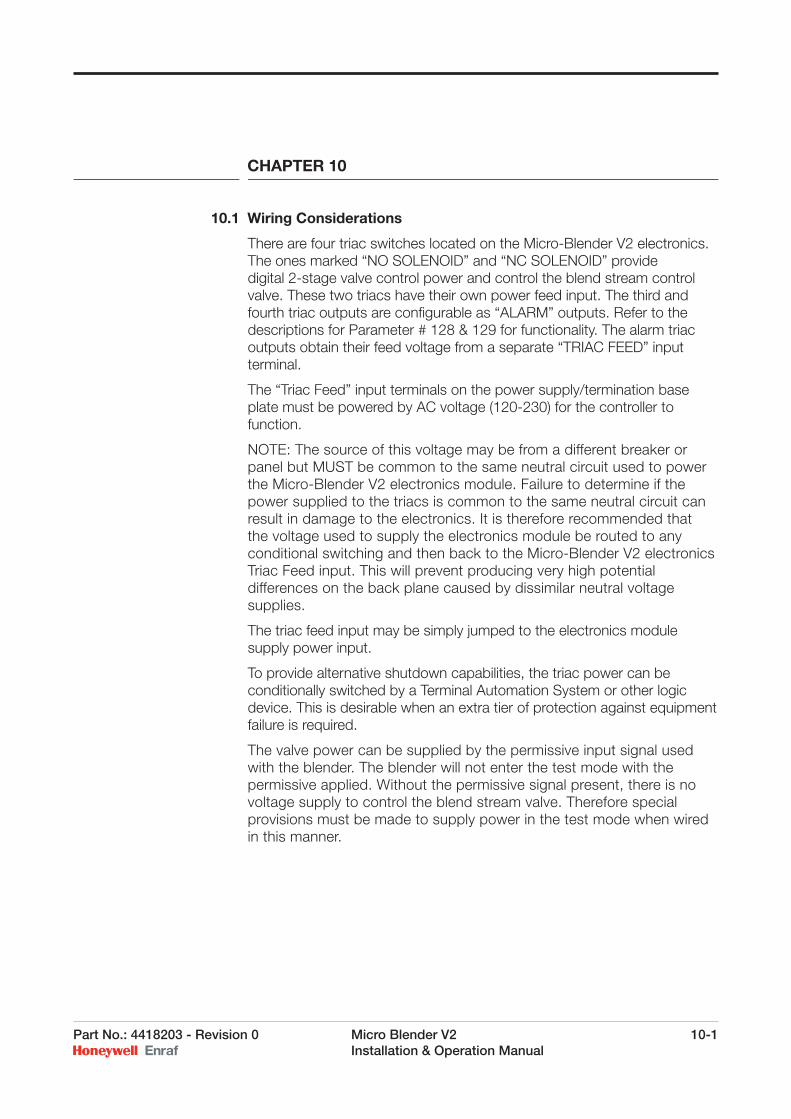
Part No.: 4418203 - Revision 0 Micro Blender V2 10-1 Installation & Operation Manual
CHAPTER 10
10.1 Wiring Considerations
There are four triac switches located on the Micro-Blender V2 electronics. The ones marked “NO SOLENOID” and “NC SOLENOID” provide digital 2-stage valve control power and control the blend stream control valve. These two triacs have their own power feed input. The third and fourth triac outputs are confi gurable as “ALARM” outputs. Refer to the descriptions for Parameter # 128 & 129 for functionality. The alarm triac outputs obtain their feed voltage from a separate “TRIAC FEED” input terminal.
The “Triac Feed” input terminals on the power supply/termination base plate must be powered by AC voltage (120-230) for the controller to function.
NOTE: The source of this voltage may be from a different breaker or panel but MUST be common to the same neutral circuit used to power the Micro-Blender V2 electronics module. Failure to determine if the power supplied to the triacs is common to the same neutral circuit can result in damage to the electronics. It is therefore recommended that the voltage used to supply the electronics module be routed to any conditional switching and then back to the Micro-Blender V2 electronics Triac Feed input. This will prevent producing very high potential differences on the back plane caused by dissimilar neutral voltage supplies.
The triac feed input may be simply jumped to the electronics module supply power input.
To provide alternative shutdown capabilities, the triac power can be conditionally switched by a Terminal Automation System or other logic device. This is desirable when an extra tier of protection against equipment failure is required.
The valve power can be supplied by the permissive input signal used with the blender. The blender will not enter the test mode with the permissive applied. Without the permissive signal present, there is no voltage supply to control the blend stream valve. Therefore special provisions must be made to supply power in the test mode when wired in this manner.
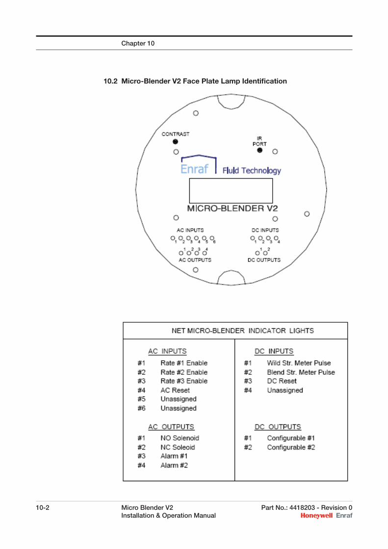
10-2 Micro Blender V2 Part No.: 4418203 - Revision 0 Installation & Operation Manual
10.2 Micro-Blender V2 Face Plate Lamp Identifi cation
Chapter 10
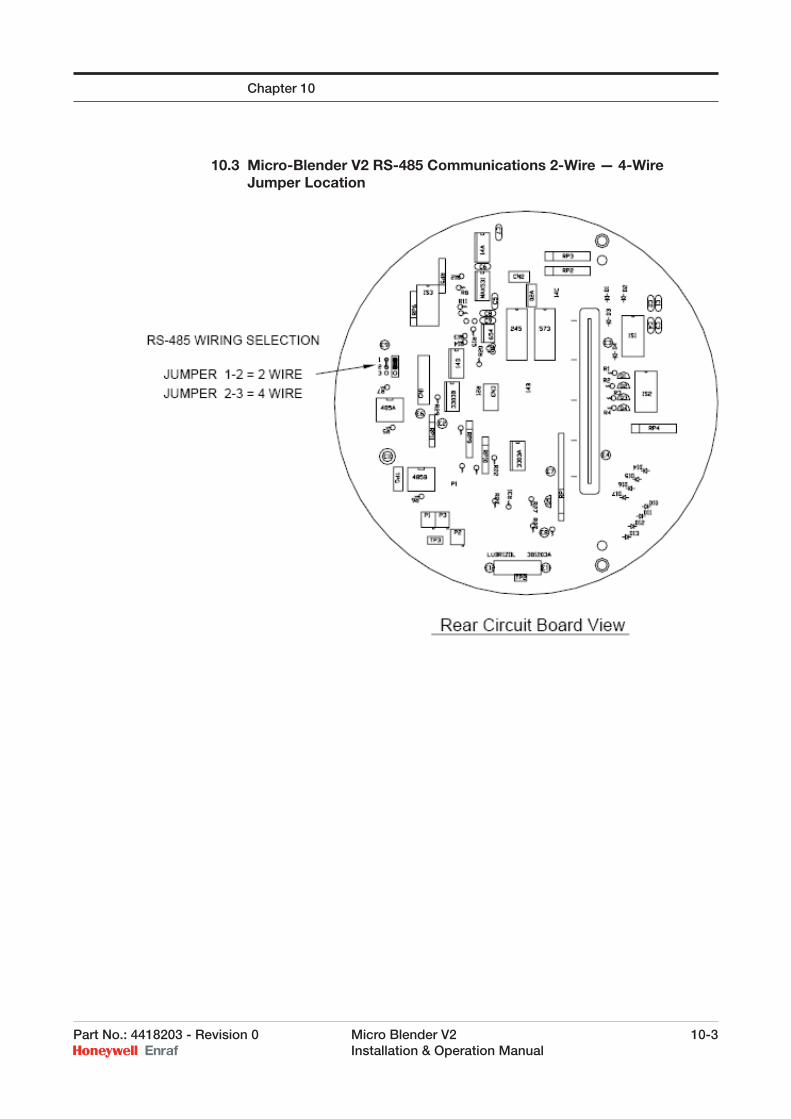
Part No.: 4418203 - Revision 0 Micro Blender V2 10-3 Installation & Operation Manual
10.3 Micro-Blender V2 RS-485 Communications 2-Wire — 4-Wire Jumper Location
Chapter 10
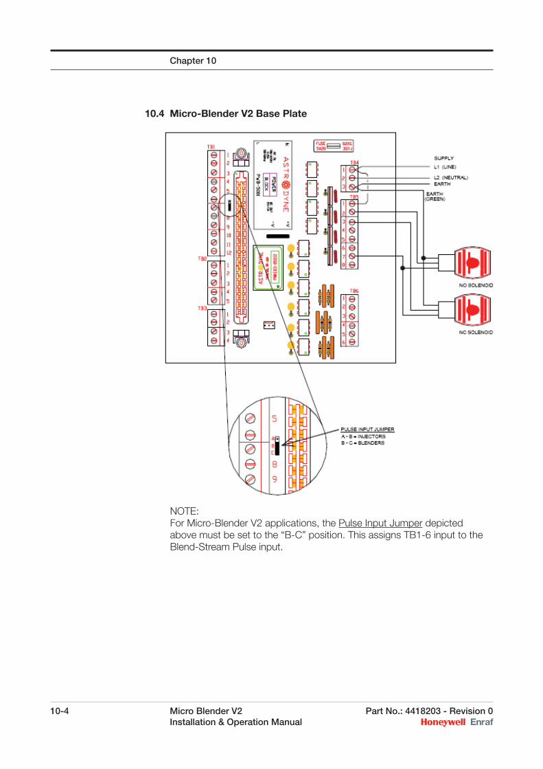
10-4 Micro Blender V2 Part No.: 4418203 - Revision 0 Installation & Operation Manual
10.4 Micro-Blender V2 Base Plate
NOTE:For Micro-Blender V2 applications, the Pulse Input Jumper depicted above must be set to the “B-C” position. This assigns TB1-6 input to the Blend-Stream Pulse input.
Chapter 10
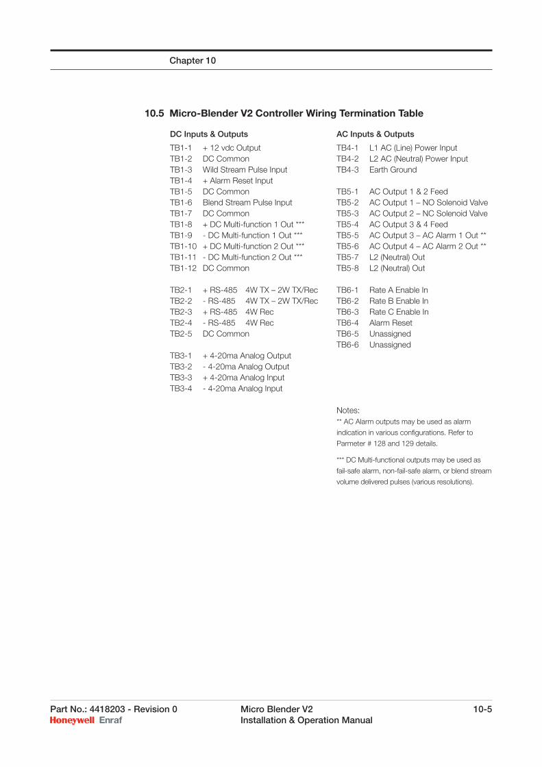
Part No.: 4418203 - Revision 0 Micro Blender V2 10-5 Installation & Operation Manual
10.5 Micro-Blender V2 Controller Wiring Termination Table
DC Inputs & Outputs
TB1-1 + 12 vdc OutputTB1-2 DC CommonTB1-3 Wild Stream Pulse InputTB1-4 + Alarm Reset InputTB1-5 DC CommonTB1-6 Blend Stream Pulse InputTB1-7 DC CommonTB1-8 + DC Multi-function 1 Out ***TB1-9 - DC Multi-function 1 Out ***TB1-10 + DC Multi-function 2 Out ***TB1-11 - DC Multi-function 2 Out ***TB1-12 DC Common
TB2-1 + RS-485 4W TX – 2W TX/RecTB2-2 - RS-485 4W TX – 2W TX/RecTB2-3 + RS-485 4W RecTB2-4 - RS-485 4W RecTB2-5 DC Common
TB3-1 + 4-20ma Analog OutputTB3-2 - 4-20ma Analog OutputTB3-3 + 4-20ma Analog InputTB3-4 - 4-20ma Analog Input
AC Inputs & Outputs
TB4-1 L1 AC (Line) Power InputTB4-2 L2 AC (Neutral) Power InputTB4-3 Earth Ground
TB5-1 AC Output 1 & 2 FeedTB5-2 AC Output 1 – NO Solenoid ValveTB5-3 AC Output 2 – NC Solenoid ValveTB5-4 AC Output 3 & 4 FeedTB5-5 AC Output 3 – AC Alarm 1 Out **TB5-6 AC Output 4 – AC Alarm 2 Out **TB5-7 L2 (Neutral) Out TB5-8 L2 (Neutral) Out
TB6-1 Rate A Enable InTB6-2 Rate B Enable InTB6-3 Rate C Enable InTB6-4 Alarm Reset TB6-5 UnassignedTB6-6 Unassigned
Notes:** AC Alarm outputs may be used as alarm
indication in various confi gurations. Refer to
Parmeter # 128 and 129 details.
*** DC Multi-functional outputs may be used as
fail-safe alarm, non-fail-safe alarm, or blend stream
volume delivered pulses (various resolutions).
Chapter 10
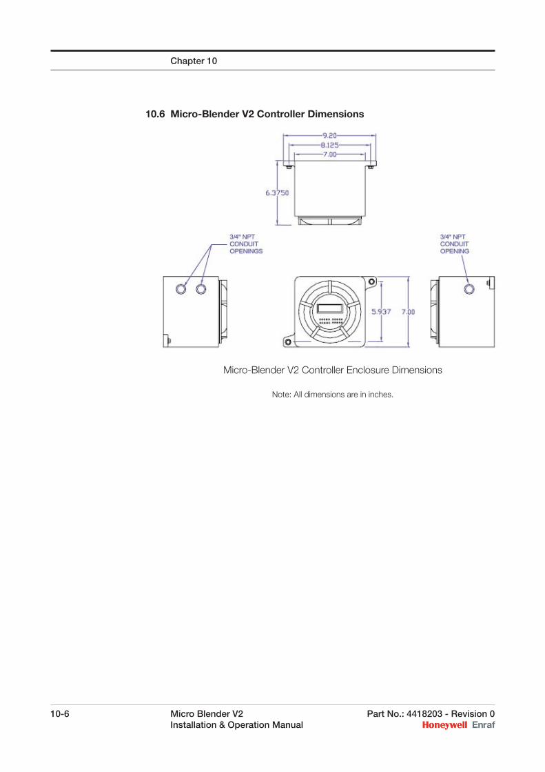
10-6 Micro Blender V2 Part No.: 4418203 - Revision 0 Installation & Operation Manual
10.6 Micro-Blender V2 Controller Dimensions
Micro-Blender V2 Controller Enclosure Dimensions
Note: All dimensions are in inches.
Chapter 10
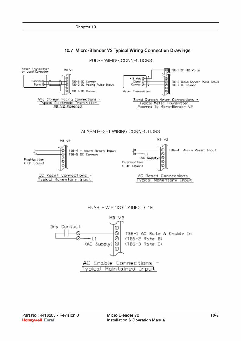
Part No.: 4418203 - Revision 0 Micro Blender V2 10-7 Installation & Operation Manual
10.7 Micro-Blender V2 Typical Wiring Connection Drawings
PULSE WIRING CONNECTIONS
ALARM RESET WIRING CONNECTIONS
ENABLE WIRING CONNECTIONS
Chapter 10
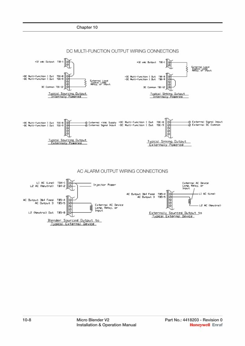
10-8 Micro Blender V2 Part No.: 4418203 - Revision 0 Installation & Operation Manual
DC MULTI-FUNCTION OUTPUT WIRING CONNECTIONS
AC ALARM OUTPUT WIRING CONNECTIONS
Chapter 10
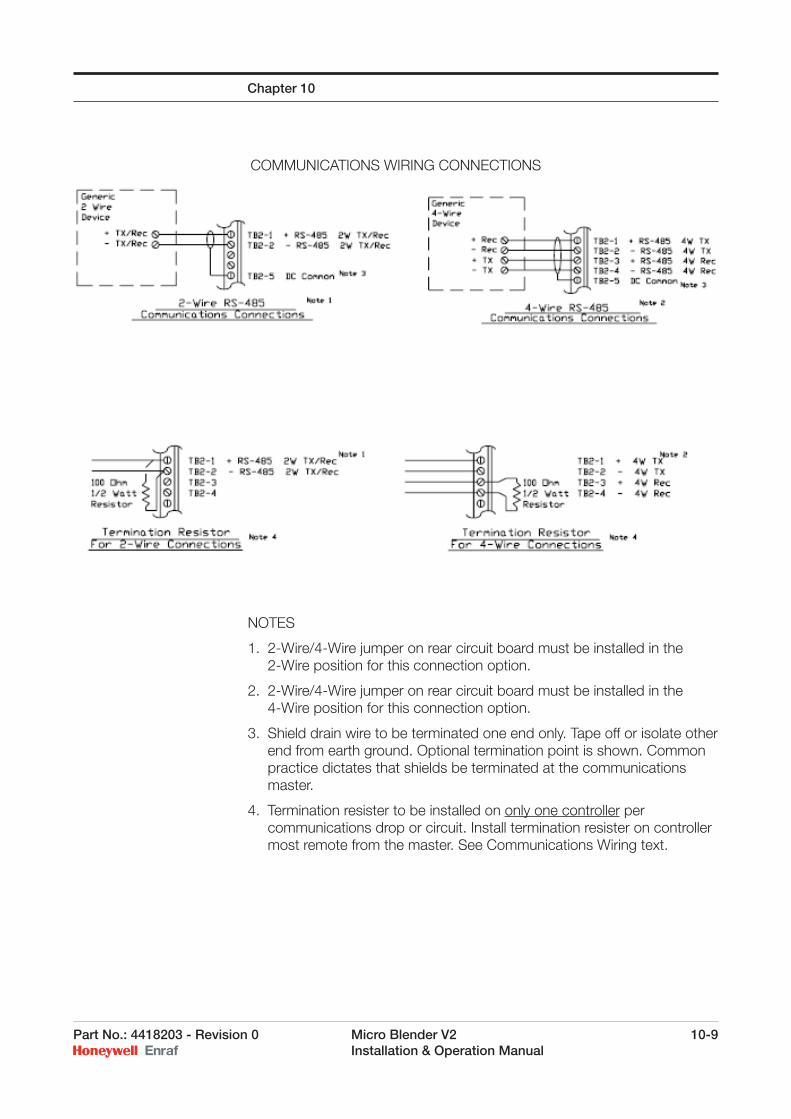
Part No.: 4418203 - Revision 0 Micro Blender V2 10-9 Installation & Operation Manual
COMMUNICATIONS WIRING CONNECTIONS
NOTES
1. 2-Wire/4-Wire jumper on rear circuit board must be installed in the 2-Wire position for this connection option.
2. 2-Wire/4-Wire jumper on rear circuit board must be installed in the 4-Wire position for this connection option.
3. Shield drain wire to be terminated one end only. Tape off or isolate other end from earth ground. Optional termination point is shown. Common practice dictates that shields be terminated at the communications master.
4. Termination resister to be installed on only one controller per communications drop or circuit. Install termination resister on controller most remote from the master. See Communications Wiring text.
Chapter 10
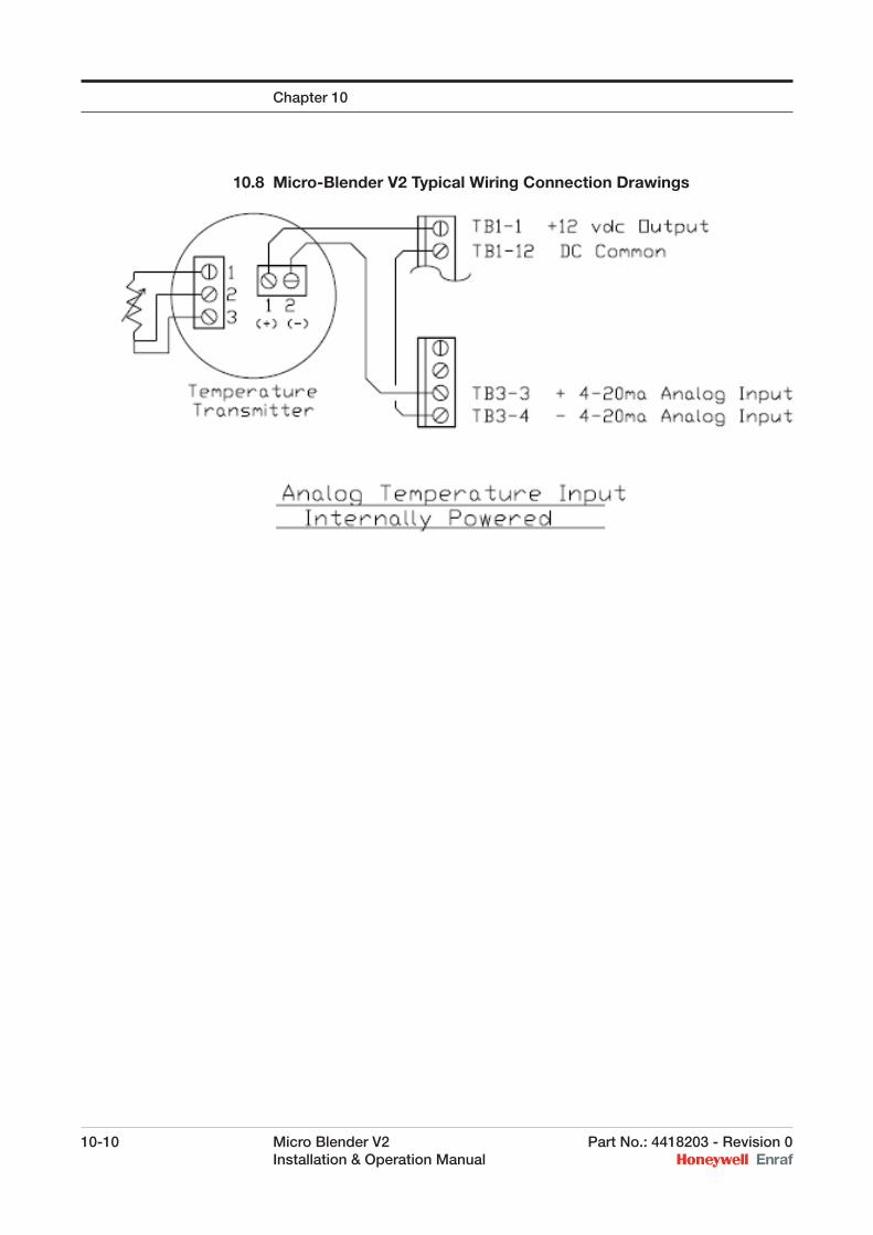
10-10 Micro Blender V2 Part No.: 4418203 - Revision 0 Installation & Operation Manual
10.8 Micro-Blender V2 Typical Wiring Connection Drawings
Chapter 10
Part No.: 4418203 - Revision 0 Micro Blender V2 11-1 Installation & Operation Manual
CHAPTER 11
11.1 Micro-Blender V2 Specifi cations
Electrical Inputs
AC Power: 90 to 265 Volts, 48 to 63 hzInstrument Current Consumption: 5 watts
AC Power Input: Fuse protected GMC-1/2
AC Status Inputs: (6) Optically isolated30K ohms (capacitive) to L2 (Neutral) @ 50hz25K ohms (capacitive) to L2 (Neutral) @ 60 hzDriving circuit must rise to greater than 85 vac for “on” state and fall below 20 vac for “off” state Maximum on-off-on frequency 5 hz.
DC Status Inputs (reset, enable, pacing):Driving circuit must sink 10 mA to within 0.8 volts of DC common, signal must rise to at least 4.5 vdc. 30 vdc open circuit maximum. Maximum pulse input frequency 1 khz.
DC Pulse Inputs:Driving circuit must sink 10 mA to within 0.8 volts of DC common, signal must rise to at least 4.5 vdc. 30 vdc open circuit maximum. Maximum pulse input frequency 1 khz.
Analog Input:4 mA = zero temperature scale20 mA = spam temperature scale100 ohms input impedance
Electrical Outputs
AC Outputs:(4) Optically isolated, AC solid state triac outputs, with two independent feeds. Feed voltage range: 24 VAC to 280 VAC. Steady state load current range: 5A (rms) maximum into an inductive load. Leakage current at maximum voltage: 100 microamps maximum.
DC Multi-functional Outputs:(2) Optically Isolated Open Collector-Open Emitter Transistor, 100 mA maximum current, 30 vdc maximum open circuit voltage. Duty cycle on pulse use: Raw = Input, 1:1, 1:10, 1:100 = 50/50, 1:1000 = 5 msec
Analog DC Output:Transistor output capable of driving 20mA into a maximum external resistance of 250 ohms. Internally powered. Maximum range determined by confi guration.
Communications:EIA RS-485 Multi-drop, poll and reply, slave only. 2-wire or 4-wire, confi gurable. 32 Controllers total on one drop. Data rates of 1200/2400 /9600/19,200 Baud supported. 8 Data bits, no parity, one stop bit, fi xed.
Other
Display:Module format: 2 Line by 14 character per lineType: Liquid crystal, backlitCharacter format: 5 by 7 dot matrix
Environmental:Ambient Operating Range: -40°F to 150°FDisplay may appear slow at temperatures below 0°F. Humidity 5 to 95% without condensation.
Enclosure Ratings:Killark GRM type, Class I, Division 1, Groups C and D. Class II, Groups E, F, and G explosion proof when installed with approved seals. Otherwise, Class I, Division 2, Groups A, B, C, and D.

11-2 Micro Blender V2 Part No.: 4418203 - Revision 0 Installation & Operation Manual
Chapter 11
Intentionally left blank.
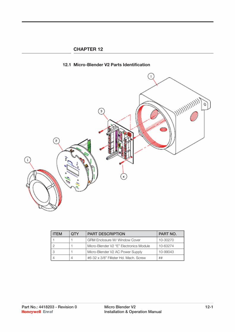
Part No.: 4418203 - Revision 0 Micro Blender V2 12-1 Installation & Operation Manual
CHAPTER 12
12.1 Micro-Blender V2 Parts Identifi cation
ITEM QTY PART DESCRIPTION PART NO.
1 1 GRM Enclosure W/ Window Cover 10-30270
2 1 Micro-Blender V2 “E” Electronics Module 10-63274
3 1 Micro-Blender V2 AC Power Supply 10-99043
4 4 #6-32 x 3/8” Fillister Hd. Mach. Screw ##

Honeywell Enraf
6 Pennant Park
Standard Way
Fareham, UK PO16 8XU
United Kingdom
Tel: +44 1329 825 823
www.honeywell.com/ps
4418203_ENGNovember 2008© 2008 Honeywell International Inc.