Embed Size (px)
Citation preview
BICRON‚NE6801 Cochran Road ! Solon, Ohio 44139 USA
Telephone: (440) 248-7400Toll Free: (800) 472-5656
Fax: (440) 349-6581http://www.bicron.com
Saint-Gobain Industrial Ceramics, Inc. ISO 9001 Quality System Certified
Micro-AnalystTM
Micro R Survey Meter
User's Manual
Publication No. 1019-0-U-1198-002
* * * Release Date * * *
November 20, 1998
Part No. 1019900Rev. C
Publication Number: 1019-0-U-1198-002Part No. 1019900, Rev. C
Replaces and supersedes: 1019-0-U-1297-001Part No. 1019900, Rev. B
Original Issue: July 1984
NOTICE
BICRON‚NE reserves the right to make changes to any product toimprove reliability, function or design and does not assume anyliability arising from either application or use of any product or circuitdescribed herein.
Information presented in this publication has been carefully checkedand is believed to be entirely reliable; however, no responsibility isassumed for inaccuracies.
Furthermore, the information does not convey to the user any licenseunder the patent rights of BICRON‚NE or others.
Specifications subject to change without notice.
LIMITED RIGHTS LEGEND
The data in this manual is considered "proprietary data". It may beduplicated and used by or on behalf of the customer with the expresslimitations the "proprietary data" may not be disclosed outside thecustomer or be used for purposes of manufacture without priorpermission of the seller.
This legend shall be marked on any reproduction of this data in wholeor in part.
(C) Copyright Saint-Gobain Industrial Ceramics, Inc., 1998All rights reserved
Printed in U.S.A.
Micro-Analyst Micro R Survey Meter1019-0-U-1198 Page 1
User's Manual
FOREWORD
This manual provides the basicinstallation, operation, and maintenanceprocedures for the Bicron Micro-AnalystTM
Micro R Survey Meter.
Section 1.0 Introduction provides a generaldescription of the instrument and its operation,and a detailed listing of its physical andperformance specifications.
Section 2.0 Battery describes the procedurefor installing and testing the batteries.
Section 3.0 Operational Modes describes theFR/h and SCA operating modes of theinstrument.
Section 4.0 Setup describes the user-adjustable controls for the SCA mode.
Section 5.0 Radiation Measurementsdescribes how to measure radiation.
Section 6.0 Audio describes the function andcontrol of the internal speaker.
Section 7.0 Selectable Response Timedescribes how to tailor response times tospecific survey situations.
Section 8.0 Circuit Description provides abrief description of the four major compon-ents of the instrument's electronic circuitry.
Section 9.0 Calibration provides directionsfor calibration of the instrument.
The Appendices are: A) QC AcceptanceProcedure, which includes calibrationprocedures, B) a Suggested Spare Parts List,C) a complete Parts List so the instrument canbe repaired on-site, and D) schematic andpictorial drawings to facilitate repairprocedures.

Micro-Analyst Micro R Survey MeterPage 2 1019-0-U-1198
User's Manual
FOREWORD (cont'd)
In order to maintain consistencythroughout this and all BICRON‚NE manuals,certain writing conventions have beenfollowed for safety warnings. They aredivided into three categories and defined asfollows:
! DANGER indicates an imminentlyhazardous situation which, if not avoided,will result in death or serious injury.DANGER NOTICES ALWAYSAPPEAR IN BOLD, ITALICIZEDUPPER CASE LETTERS.
! WARNING indicates a potentiallyhazardous situation which, if not avoided,could result in death or serious injury.WARNING NOTICES ALWAYSAPPEAR IN UPPERCASE BOLDLETTERS.
! CAUTION indicates a potentiallyhazardous situation which, if not avoided,may result in minor or moderate injury. Itmay also be used to alert against unsafepractices. CAUTION notices alwaysappear in bold, italicized letters.
The definition of these safety warnings isaccording to ANSI Z535.4. The style of thewarnings (bold, italicized, etc.) isBICRON‚NE's.
In addition to the above, we have addedthe following warning:
! NOTE indicates a situation which has thepotential for erroneous data collection, ordamage to equipment, but which does notdirectly affect the safety of the operatorwith respect to this product. Theresponsibility for any safety consequencesas a result of erroneous data lies solelywith the operator. NOTE notices alwaysappear in italics.
Micro-Analyst Micro R Survey Meter1019-0-U-1198 Page 3
User's Manual
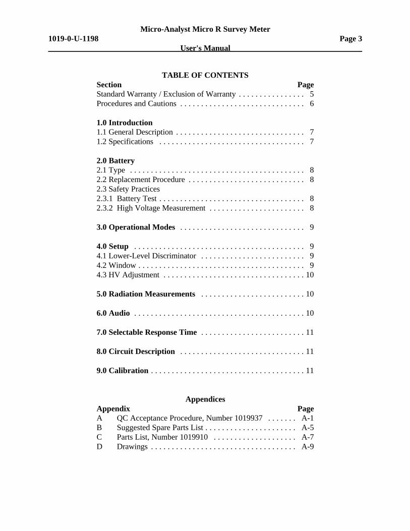
TABLE OF CONTENTSSection PageStandard Warranty / Exclusion of Warranty . . . . . . . . . . . . . . . . 5Procedures and Cautions . . . . . . . . . . . . . . . . . . . . . . . . . . . . . . 6
1.0 Introduction1.1 General Description . . . . . . . . . . . . . . . . . . . . . . . . . . . . . . . 71.2 Specifications . . . . . . . . . . . . . . . . . . . . . . . . . . . . . . . . . . . 7
2.0 Battery2.1 Type . . . . . . . . . . . . . . . . . . . . . . . . . . . . . . . . . . . . . . . . . . 82.2 Replacement Procedure . . . . . . . . . . . . . . . . . . . . . . . . . . . . 82.3 Safety Practices2.3.1 Battery Test . . . . . . . . . . . . . . . . . . . . . . . . . . . . . . . . . . . 82.3.2 High Voltage Measurement . . . . . . . . . . . . . . . . . . . . . . . 8
3.0 Operational Modes . . . . . . . . . . . . . . . . . . . . . . . . . . . . . . 9
4.0 Setup . . . . . . . . . . . . . . . . . . . . . . . . . . . . . . . . . . . . . . . . . 94.1 Lower-Level Discriminator . . . . . . . . . . . . . . . . . . . . . . . . . 94.2 Window . . . . . . . . . . . . . . . . . . . . . . . . . . . . . . . . . . . . . . . . 94.3 HV Adjustment . . . . . . . . . . . . . . . . . . . . . . . . . . . . . . . . . . 10
5.0 Radiation Measurements . . . . . . . . . . . . . . . . . . . . . . . . . 10
6.0 Audio . . . . . . . . . . . . . . . . . . . . . . . . . . . . . . . . . . . . . . . . . 10
7.0 Selectable Response Time . . . . . . . . . . . . . . . . . . . . . . . . . 11
8.0 Circuit Description . . . . . . . . . . . . . . . . . . . . . . . . . . . . . . 11
9.0 Calibration . . . . . . . . . . . . . . . . . . . . . . . . . . . . . . . . . . . . . 11
AppendicesAppendix PageA QC Acceptance Procedure, Number 1019937 . . . . . . . A-1B Suggested Spare Parts List . . . . . . . . . . . . . . . . . . . . . . A-5C Parts List, Number 1019910 . . . . . . . . . . . . . . . . . . . . A-7D Drawings . . . . . . . . . . . . . . . . . . . . . . . . . . . . . . . . . . . A-9
Micro-Analyst Micro R Survey MeterPage 4 1019-0-U-1198
User's Manual
BLANK PAGE
Micro-Analyst Micro R Survey Meter1019-0-U-1198 Page 5
User's Manual
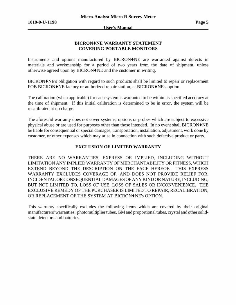
BICRON‚‚NE WARRANTY STATEMENTCOVERING PORTABLE MONITORS
Instruments and options manufactured by BICRON‚NE are warranted against defects inmaterials and workmanship for a period of two years from the date of shipment, unlessotherwise agreed upon by BICRON‚NE and the customer in writing.
BICRON‚NE's obligation with regard to such products shall be limited to repair or replacementFOB BICRON‚NE factory or authorized repair station, at BICRON‚NE's option.
The calibration (when applicable) for each system is warranted to be within its specified accuracy atthe time of shipment. If this initial calibration is determined to be in error, the system will berecalibrated at no charge.
The aforesaid warranty does not cover systems, options or probes which are subject to excessivephysical abuse or are used for purposes other than those intended. In no event shall BICRON‚NEbe liable for consequential or special damages, transportation, installation, adjustment, work done bycustomer, or other expenses which may arise in connection with such defective product or parts.
EXCLUSION OF LIMITED WARRANTY
THERE ARE NO WARRANTIES, EXPRESS OR IMPLIED, INCLUDING WITHOUTLIMITATION ANY IMPLIED WARRANTY OF MERCHANTABILITY OR FITNESS, WHICHEXTEND BEYOND THE DESCRIPTION ON THE FACE HEREOF. THIS EXPRESSWARRANTY EXCLUDES COVERAGE OF, AND DOES NOT PROVIDE RELIEF FOR,INCIDENTAL OR CONSEQUENTIAL DAMAGES OF ANY KIND OR NATURE, INCLUDING,BUT NOT LIMITED TO, LOSS OF USE, LOSS OF SALES OR INCONVENIENCE. THEEXCLUSIVE REMEDY OF THE PURCHASER IS LIMITED TO REPAIR, RECALIBRATION,OR REPLACEMENT OF THE SYSTEM AT BICRON‚NE's OPTION.
This warranty specifically excludes the following items which are covered by their originalmanufacturers' warranties: photomultiplier tubes, GM and proportional tubes, crystal and other solid-state detectors and batteries.
Micro-Analyst Micro R Survey MeterPage 6 1019-0-U-1198
User's Manual
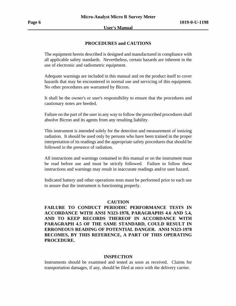
PROCEDURES and CAUTIONS
The equipment herein described is designed and manufactured in compliance withall applicable safety standards. Nevertheless, certain hazards are inherent in theuse of electronic and radiometric equipment.
Adequate warnings are included in this manual and on the product itself to coverhazards that may be encountered in normal use and servicing of this equipment.No other procedures are warranted by Bicron.
It shall be the owner's or user's responsibility to ensure that the procedures andcautionary notes are heeded.
Failure on the part of the user in any way to follow the prescribed procedures shallabsolve Bicron and its agents from any resulting liability.
This instrument is intended solely for the detection and measurement of ionizingradiation. It should be used only by persons who have been trained in the properinterpretation of its readings and the appropriate safety procedures that should befollowed in the presence of radiation.
All instructions and warnings contained in this manual or on the instrument mustbe read before use and must be strictly followed. Failure to follow theseinstructions and warnings may result in inaccurate readings and/or user hazard.
Indicated battery and other operations tests must be performed prior to each useto assure that the instrument is functioning properly.
CAUTIONFAILURE TO CONDUCT PERIODIC PERFORMANCE TESTS INACCORDANCE WITH ANSI N323-1978, PARAGRAPHS 4.6 AND 5.4,AND TO KEEP RECORDS THEREOF IN ACCORDANCE WITHPARAGRAPH 4.5 OF THE SAME STANDARD, COULD RESULT INERRONEOUS READING OF POTENTIAL DANGER. ANSI N323-1978BECOMES, BY THIS REFERENCE, A PART OF THIS OPERATINGPROCEDURE.
INSPECTIONInstruments should be examined and tested as soon as received. Claims fortransportation damages, if any, should be filed at once with the delivery carrier.
Micro-Analyst Micro R Survey Meter1019-0-U-1198 Page 7
User's Manual
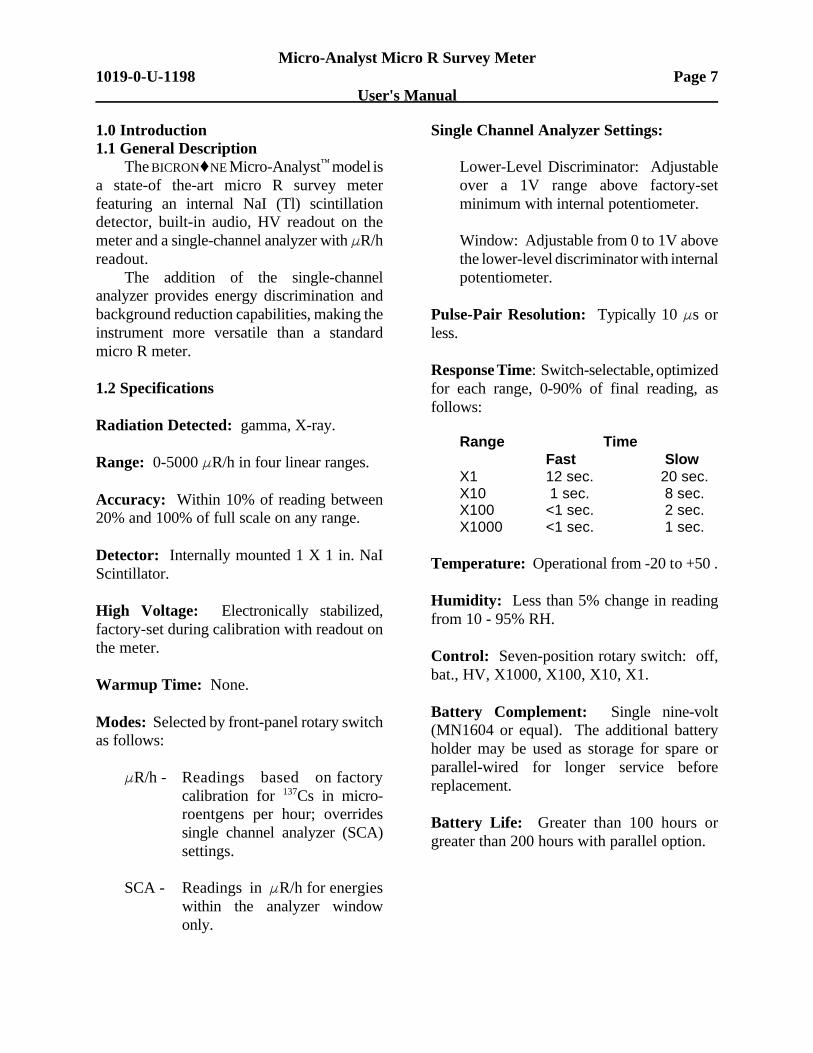
1.0 Introduction1.1 General Description
The BICRON‚NE Micro-Analyst™ model isa state-of the-art micro R survey meterfeaturing an internal NaI (Tl) scintillationdetector, built-in audio, HV readout on themeter and a single-channel analyzer with FR/hreadout.
The addition of the single-channelanalyzer provides energy discrimination andbackground reduction capabilities, making theinstrument more versatile than a standardmicro R meter.
1.2 Specifications
Radiation Detected: gamma, X-ray.
Range: 0-5000 FR/h in four linear ranges.
Accuracy: Within 10% of reading between20% and 100% of full scale on any range.
Detector: Internally mounted 1 X 1 in. NaIScintillator.
High Voltage: Electronically stabilized,factory-set during calibration with readout onthe meter.
Warmup Time: None.
Modes: Selected by front-panel rotary switchas follows:
FR/h - Readings based on factorycalibration for 137Cs in micro-roentgens per hour; overridessingle channel analyzer (SCA)settings.
SCA - Readings in FR/h for energieswithin the analyzer windowonly.
Single Channel Analyzer Settings:
Lower-Level Discriminator: Adjustableover a 1V range above factory-setminimum with internal potentiometer.
Window: Adjustable from 0 to 1V abovethe lower-level discriminator with internalpotentiometer.
Pulse-Pair Resolution: Typically 10 Fs orless.
Response Time: Switch-selectable, optimizedfor each range, 0-90% of final reading, asfollows:
Range TimeFast Slow
X1 12 sec. 20 sec.X10 1 sec. 8 sec.X100 <1 sec. 2 sec.X1000 <1 sec. 1 sec.
Temperature: Operational from -20Bto +50B.
Humidity: Less than 5% change in readingfrom 10 - 95% RH.
Control: Seven-position rotary switch: off,bat., HV, X1000, X100, X10, X1.
Battery Complement: Single nine-volt(MN1604 or equal). The additional batteryholder may be used as storage for spare orparallel-wired for longer service beforereplacement.
Battery Life: Greater than 100 hours orgreater than 200 hours with parallel option.
Micro-Analyst Micro R Survey MeterPage 8 1019-0-U-1198
User's Manual
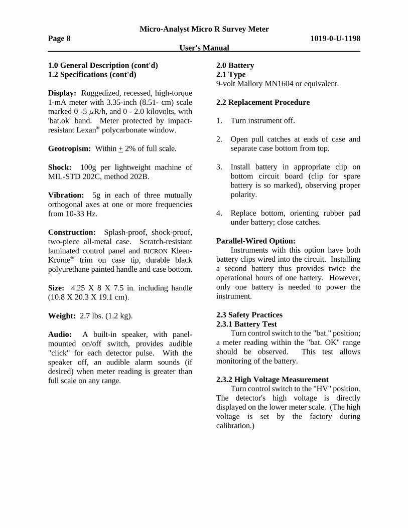
1.0 General Description (cont'd)1.2 Specifications (cont'd)
Display: Ruggedized, recessed, high-torque1-mA meter with 3.35-inch (8.51- cm) scalemarked 0 -5 FR/h, and 0 - 2.0 kilovolts, with'bat.ok' band. Meter protected by impact-resistant Lexan® polycarbonate window.
Geotropism: Within + 2% of full scale.
Shock: 100g per lightweight machine ofMIL-STD 202C, method 202B.
Vibration: 5g in each of three mutuallyorthogonal axes at one or more frequenciesfrom 10-33 Hz.
Construction: Splash-proof, shock-proof,two-piece all-metal case. Scratch-resistantlaminated control panel and BICRON Kleen-Krome® trim on case tip, durable blackpolyurethane painted handle and case bottom.
Size: 4.25 X 8 X 7.5 in. including handle(10.8 X 20.3 X 19.1 cm).
Weight: 2.7 lbs. (1.2 kg).
Audio: A built-in speaker, with panel-mounted on/off switch, provides audible"click" for each detector pulse. With thespeaker off, an audible alarm sounds (ifdesired) when meter reading is greater thanfull scale on any range.
2.0 Battery2.1 Type9-volt Mallory MN1604 or equivalent.
2.2 Replacement Procedure
1. Turn instrument off.
2. Open pull catches at ends of case andseparate case bottom from top.
3. Install battery in appropriate clip onbottom circuit board (clip for sparebattery is so marked), observing properpolarity.
4. Replace bottom, orienting rubber padunder battery; close catches.
Parallel-Wired Option:Instruments with this option have both
battery clips wired into the circuit. Installinga second battery thus provides twice theoperational hours of one battery. However,only one battery is needed to power theinstrument.
2.3 Safety Practices2.3.1 Battery Test
Turn control switch to the "bat." position;a meter reading within the "bat. OK" rangeshould be observed. This test allowsmonitoring of the battery.
2.3.2 High Voltage MeasurementTurn control switch to the "HV" position.
The detector's high voltage is directlydisplayed on the lower meter scale. (The highvoltage is set by the factory duringcalibration.)
Micro-Analyst Micro R Survey Meter1019-0-U-1198 Page 9
User's Manual
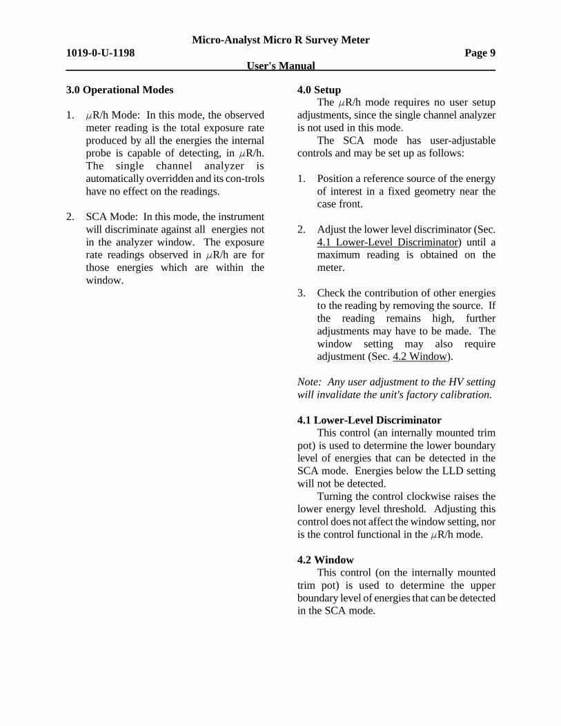
3.0 Operational Modes
1. FR/h Mode: In this mode, the observedmeter reading is the total exposure rateproduced by all the energies the internalprobe is capable of detecting, in FR/h.The single channel analyzer isautomatically overridden and its con-trolshave no effect on the readings.
2. SCA Mode: In this mode, the instrumentwill discriminate against all energies notin the analyzer window. The exposurerate readings observed in FR/h are forthose energies which are within thewindow.
4.0 SetupThe FR/h mode requires no user setup
adjustments, since the single channel analyzeris not used in this mode.
The SCA mode has user-adjustablecontrols and may be set up as follows:
1. Position a reference source of the energyof interest in a fixed geometry near thecase front.
2. Adjust the lower level discriminator (Sec.4.1 Lower-Level Discriminator) until amaximum reading is obtained on themeter.
3. Check the contribution of other energiesto the reading by removing the source. Ifthe reading remains high, furtheradjustments may have to be made. Thewindow setting may also requireadjustment (Sec. 4.2 Window).
Note: Any user adjustment to the HV settingwill invalidate the unit's factory calibration.
4.1 Lower-Level DiscriminatorThis control (an internally mounted trim
pot) is used to determine the lower boundarylevel of energies that can be detected in theSCA mode. Energies below the LLD settingwill not be detected.
Turning the control clockwise raises thelower energy level threshold. Adjusting thiscontrol does not affect the window setting, noris the control functional in the FR/h mode.
4.2 WindowThis control (on the internally mounted
trim pot) is used to determine the upperboundary level of energies that can be detectedin the SCA mode.
Micro-Analyst Micro R Survey MeterPage 10 1019-0-U-1198
User's Manual
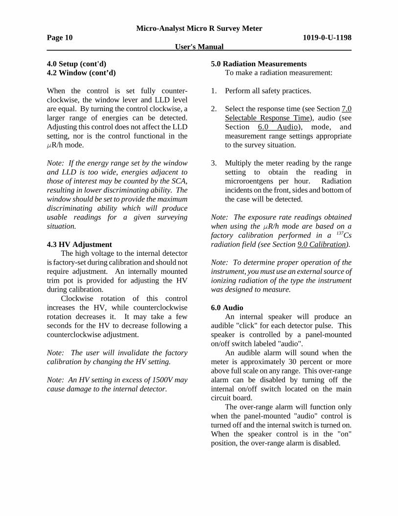
4.0 Setup (cont'd)4.2 Window (cont’d)
When the control is set fully counter-clockwise, the window lever and LLD levelare equal. By turning the control clockwise, alarger range of energies can be detected.Adjusting this control does not affect the LLDsetting, nor is the control functional in theFR/h mode.
Note: If the energy range set by the windowand LLD is too wide, energies adjacent tothose of interest may be counted by the SCA,resulting in lower discriminating ability. Thewindow should be set to provide the maximumdiscriminating ability which will produceusable readings for a given surveyingsituation.
4.3 HV AdjustmentThe high voltage to the internal detector
is factory-set during calibration and should notrequire adjustment. An internally mountedtrim pot is provided for adjusting the HVduring calibration.
Clockwise rotation of this controlincreases the HV, while counterclockwiserotation decreases it. It may take a fewseconds for the HV to decrease following acounterclockwise adjustment.
Note: The user will invalidate the factorycalibration by changing the HV setting.
Note: An HV setting in excess of 1500V maycause damage to the internal detector.
5.0 Radiation MeasurementsTo make a radiation measurement:
1. Perform all safety practices.
2. Select the response time (see Section 7.0Selectable Response Time), audio (seeSection 6.0 Audio), mode, andmeasurement range settings appropriateto the survey situation.
3. Multiply the meter reading by the rangesetting to obtain the reading inmicroroentgens per hour. Radiationincidents on the front, sides and bottom ofthe case will be detected.
Note: The exposure rate readings obtainedwhen using the FR/h mode are based on afactory calibration performed in a 137Csradiation field (see Section 9.0 Calibration).
Note: To determine proper operation of theinstrument, you must use an external source ofionizing radiation of the type the instrumentwas designed to measure.
6.0 AudioAn internal speaker will produce an
audible "click" for each detector pulse. Thisspeaker is controlled by a panel-mountedon/off switch labeled "audio".
An audible alarm will sound when themeter is approximately 30 percent or moreabove full scale on any range. This over-rangealarm can be disabled by turning off theinternal on/off switch located on the maincircuit board.
The over-range alarm will function onlywhen the panel-mounted "audio" control isturned off and the internal switch is turned on.When the speaker control is in the "on"position, the over-range alarm is disabled.
Micro-Analyst Micro R Survey Meter1019-0-U-1198 Page 11
User's Manual
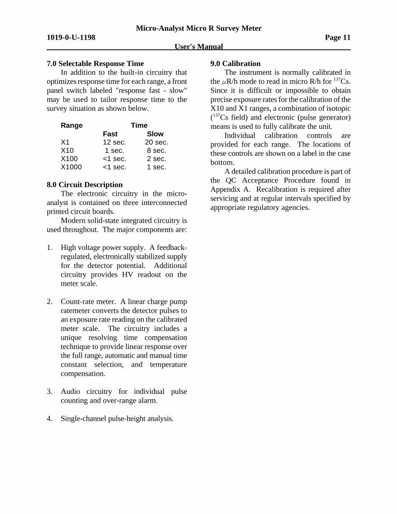
7.0 Selectable Response TimeIn addition to the built-in circuitry that
optimizes response time for each range, a frontpanel switch labeled "response fast - slow"may be used to tailor response time to thesurvey situation as shown below.
Range TimeFast Slow
X1 12 sec. 20 sec.X10 1 sec. 8 sec.X100 <1 sec. 2 sec.X1000 <1 sec. 1 sec.
8.0 Circuit DescriptionThe electronic circuitry in the micro-
analyst is contained on three interconnectedprinted circuit boards.
Modern solid-state integrated circuitry isused throughout. The major components are:
1. High voltage power supply. A feedback-regulated, electronically stabilized supplyfor the detector potential. Additionalcircuitry provides HV readout on themeter scale.
2. Count-rate meter. A linear charge pumpratemeter converts the detector pulses toan exposure rate reading on the calibratedmeter scale. The circuitry includes aunique resolving time compensationtechnique to provide linear response overthe full range, automatic and manual timeconstant selection, and temperaturecompensation.
3. Audio circuitry for individual pulsecounting and over-range alarm.
4. Single-channel pulse-height analysis.
9.0 CalibrationThe instrument is normally calibrated in
the FR/h mode to read in micro R/h for 137Cs.Since it is difficult or impossible to obtainprecise exposure rates for the calibration of theX10 and X1 ranges, a combination of isotopic(137Cs field) and electronic (pulse generator)means is used to fully calibrate the unit.
Individual calibration controls areprovided for each range. The locations ofthese controls are shown on a label in the casebottom.
A detailed calibration procedure is part ofthe QC Acceptance Procedure found inAppendix A. Recalibration is required afterservicing and at regular intervals specified byappropriate regulatory agencies.

Micro-Analyst Micro R Survey MeterPage 12 1019-0-U-1198
User's Manual
BLANK PAGE
Micro-Analyst Micro R Survey Meter1019-0-U-1198 Page A-1
User's Manual
Appendix AQC Acceptance Procedure, No. 1019937
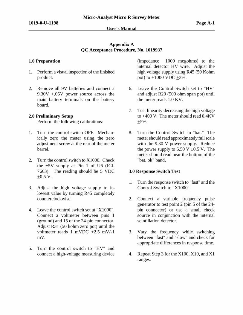
1.0 Preparation
1. Perform a visual inspection of the finishedproduct.
2. Remove all 9V batteries and connect a9.30V +.05V power source across themain battery terminals on the batteryboard.
2.0 Preliminary SetupPerform the following calibrations:
1. Turn the control switch OFF. Mechan-ically zero the meter using the zeroadjustment screw at the rear of the meterbarrel.
2. Turn the control switch to X1000. Checkthe +5V supply at Pin 1 of U6 (ICL7663). The reading should be 5 VDC+0.5 V.
3. Adjust the high voltage supply to itslowest value by turning R45 completelycounterclockwise.
4. Leave the control switch set at "X1000".Connect a voltmeter between pins 1(ground) and 15 of the 24-pin connector.Adjust R31 (50 kohm zero pot) until thevoltmeter reads 1 mVDC +2.5 mV/-1mV.
5. Turn the control switch to "HV" andconnect a high-voltage measuring device
(impedance #1000 megohms) to theinternal detector HV wire. Adjust thehigh voltage supply using R45 (50 Kohmpot) to +1000 VDC +3%.
6. Leave the Control Switch set to "HV"and adjust R29 (500 ohm span pot) untilthe meter reads 1.0 KV.
7. Test linearity decreasing the high voltageto +400 V. The meter should read 0.4KV+5%.
8. Turn the Control Switch to "bat." Themeter should read approximately full scalewith the 9.30 V power supply. Reducethe power supply to 6.50 V ±0.5 V. Themeter should read near the bottom of the"bat. ok" band.
3.0 Response Switch Test
1. Turn the response switch to "fast" and theControl Switch to "X1000".
2. Connect a variable frequency pulsegenerator to test point 2 (pin 5 of the 24-pin connector) or use a small checksource in conjunction with the internalscintillation detector.
3. Vary the frequency while switchingbetween "fast" and "slow" and check forappropriate differences in response time.
4. Repeat Step 3 for the X100, X10, and X1ranges.
Micro-Analyst Micro R Survey MeterPage A-2 1019-0-U-1198
User's Manual
Appendix AQC Acceptance Procedure, No. 1019937 (cont'd)
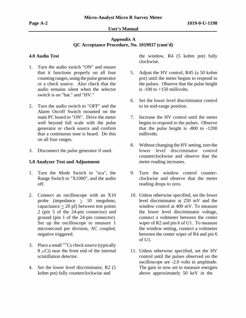
4.0 Audio Test
1. Turn the audio switch "ON" and ensurethat it functions properly on all fourcounting ranges, using the pulse generatoror a check source. Also check that theaudio remains silent when the selectorswitch is on "bat." and "HV."
2. Turn the audio switch to "OFF" and theAlarm On/off Switch mounted on themain PC board to "ON". Drive the meterwell beyond full scale with the pulsegenerator or check source and confirmthat a continuous tone is heard. Do thison all four ranges.
3. Disconnect the pulse generator if used.
5.0 Analyzer Test and Adjustment
1. Turn the Mode Switch to "sca", theRange Switch to "X1000", and the audiooff.
2. Connect an oscilloscope with an X10probe (impedance > 10 megohms,capacitance < 20 pf) between test points2 (pin 5 of the 24-pin connector) andground (pin 1 of the 24-pin connector).Set up the oscilloscope to measure 1microsecond per division, AC coupled,negative triggered.
3. Place a small 137Cs check source (typically8 FCi) near the front end of the internalscintillation detector.
4. Set the lower level discriminator, R2 (5kohm pot) fully counterclockwise and
the window, R4 (5 kohm pot) fullyclockwise.
5. Adjust the HV control, R45 (a 50 kohmpot) until the meter begins to respond tothe pulses. Observe that the pulse heightis -100 to +150 millivolts.
6. Set the lower level discriminator controlto its mid-range position.
7. Increase the HV control until the meterbegins to respond to the pulses. Observethat the pulse height is -800 to -1200millivolts.
8. Without changing the HV setting, turn thelower level discriminator controlcounterclockwise and observe that themeter reading increases.
9. Turn the window control counter-clockwise and observe that the meterreading drops to zero.
10. Unless otherwise specified, set the lowerlevel discriminator at 250 mV and thewindow control at 400 mV. To measurethe lower level discriminator voltage,connect a voltmeter between the centerwiper of R2 and pin 6 of U1. To measurethe window setting, connect a voltmeterbetween the center wiper of R4 and pin 6of U1.
11. Unless otherwise specified, set the HVcontrol until the pulses observed on theoscilloscope are -2.0 volts in amplitude.The gain in now set to measure energiesabove approximately 50 keV in the
Micro-Analyst Micro R Survey Meter1019-0-U-1198 Page A-3
User's Manual
Appendix AQC Acceptance Procedure, No. 1019937 (cont'd)
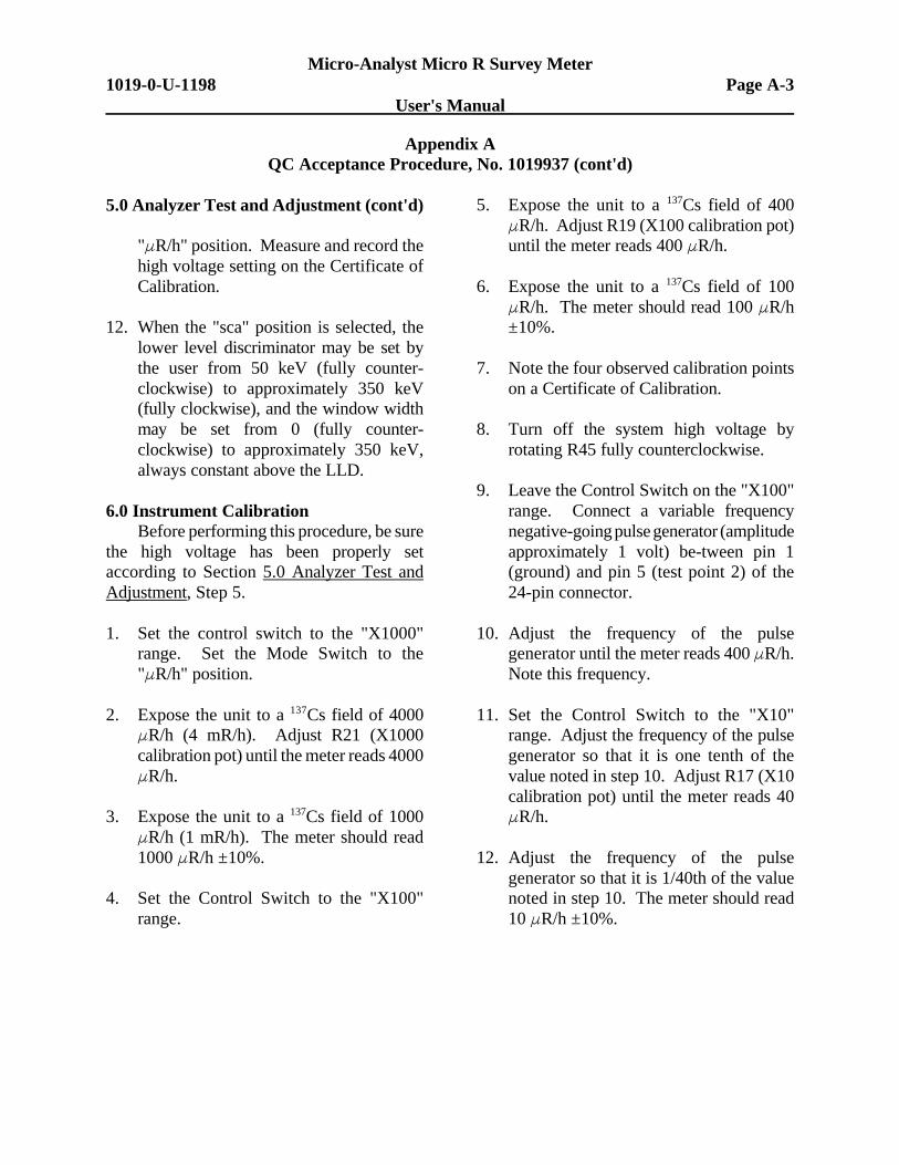
5.0 Analyzer Test and Adjustment (cont'd)
"FR/h" position. Measure and record thehigh voltage setting on the Certificate ofCalibration.
12. When the "sca" position is selected, thelower level discriminator may be set bythe user from 50 keV (fully counter-clockwise) to approximately 350 keV(fully clockwise), and the window widthmay be set from 0 (fully counter-clockwise) to approximately 350 keV,always constant above the LLD.
6.0 Instrument CalibrationBefore performing this procedure, be sure
the high voltage has been properly setaccording to Section 5.0 Analyzer Test andAdjustment, Step 5.
1. Set the control switch to the "X1000"range. Set the Mode Switch to the"FR/h" position.
2. Expose the unit to a 137Cs field of 4000FR/h (4 mR/h). Adjust R21 (X1000calibration pot) until the meter reads 4000FR/h.
3. Expose the unit to a 137Cs field of 1000FR/h (1 mR/h). The meter should read1000 FR/h ±10%.
4. Set the Control Switch to the "X100"range.
5. Expose the unit to a 137Cs field of 400FR/h. Adjust R19 (X100 calibration pot)until the meter reads 400 FR/h.
6. Expose the unit to a 137Cs field of 100FR/h. The meter should read 100 FR/h±10%.
7. Note the four observed calibration pointson a Certificate of Calibration.
8. Turn off the system high voltage byrotating R45 fully counterclockwise.
9. Leave the Control Switch on the "X100"range. Connect a variable frequencynegative-going pulse generator (amplitudeapproximately 1 volt) be-tween pin 1(ground) and pin 5 (test point 2) of the24-pin connector.
10. Adjust the frequency of the pulsegenerator until the meter reads 400 FR/h.Note this frequency.
11. Set the Control Switch to the "X10"range. Adjust the frequency of the pulsegenerator so that it is one tenth of thevalue noted in step 10. Adjust R17 (X10calibration pot) until the meter reads 40FR/h.
12. Adjust the frequency of the pulsegenerator so that it is 1/40th of the valuenoted in step 10. The meter should read10 FR/h ±10%.
Micro-Analyst Micro R Survey MeterPage A-4 1019-0-U-1198
User's Manual
Appendix AQC Acceptance Procedure, No. 1019937 (cont'd)
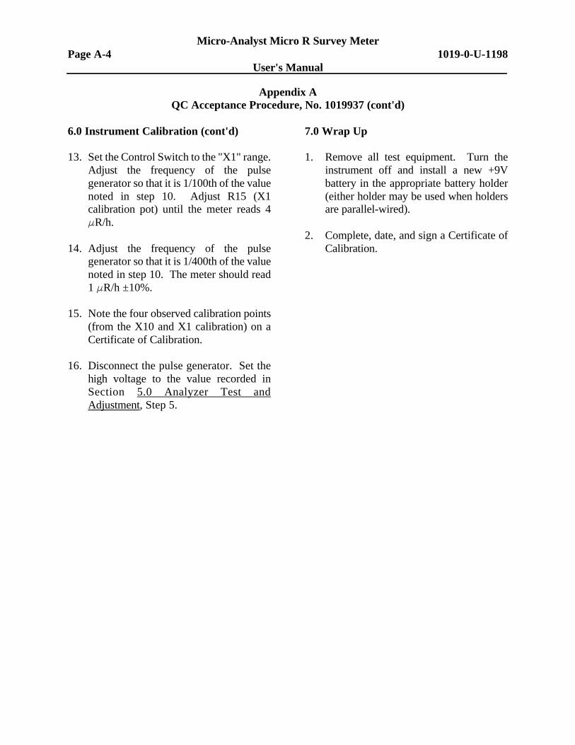
6.0 Instrument Calibration (cont'd)
13. Set the Control Switch to the "X1" range.Adjust the frequency of the pulsegenerator so that it is 1/100th of the valuenoted in step 10. Adjust R15 (X1calibration pot) until the meter reads 4FR/h.
14. Adjust the frequency of the pulsegenerator so that it is 1/400th of the valuenoted in step 10. The meter should read1 FR/h ±10%.
15. Note the four observed calibration points(from the X10 and X1 calibration) on aCertificate of Calibration.
16. Disconnect the pulse generator. Set thehigh voltage to the value recorded inSection 5.0 Analyzer Test andAdjustment, Step 5.
7.0 Wrap Up
1. Remove all test equipment. Turn theinstrument off and install a new +9Vbattery in the appropriate battery holder(either holder may be used when holdersare parallel-wired).
2. Complete, date, and sign a Certificate ofCalibration.
Micro-Analyst Micro R Survey Meter1019-0-U-1198 Page A-5
User's Manual
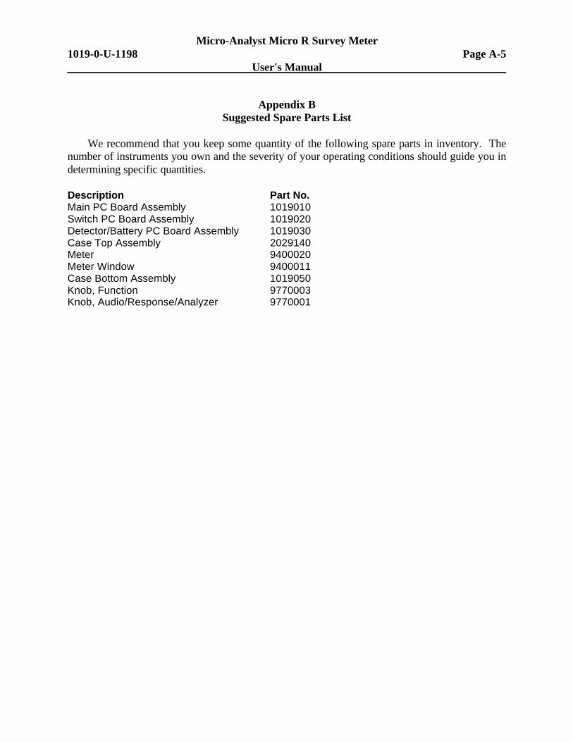
Appendix BSuggested Spare Parts List
We recommend that you keep some quantity of the following spare parts in inventory. Thenumber of instruments you own and the severity of your operating conditions should guide you indetermining specific quantities.
Description Part No.Main PC Board Assembly 1019010Switch PC Board Assembly 1019020Detector/Battery PC Board Assembly 1019030Case Top Assembly 2029140Meter 9400020Meter Window 9400011Case Bottom Assembly 1019050Knob, Function 9770003Knob, Audio/Response/Analyzer 9770001

Micro-Analyst Micro R Survey MeterPage A-6 1019-0-U-1198
User's Manual
BLANK PAGE
Micro-Analyst Micro R Survey Meter1019-0-U-1198 Page A-7
User's Manual
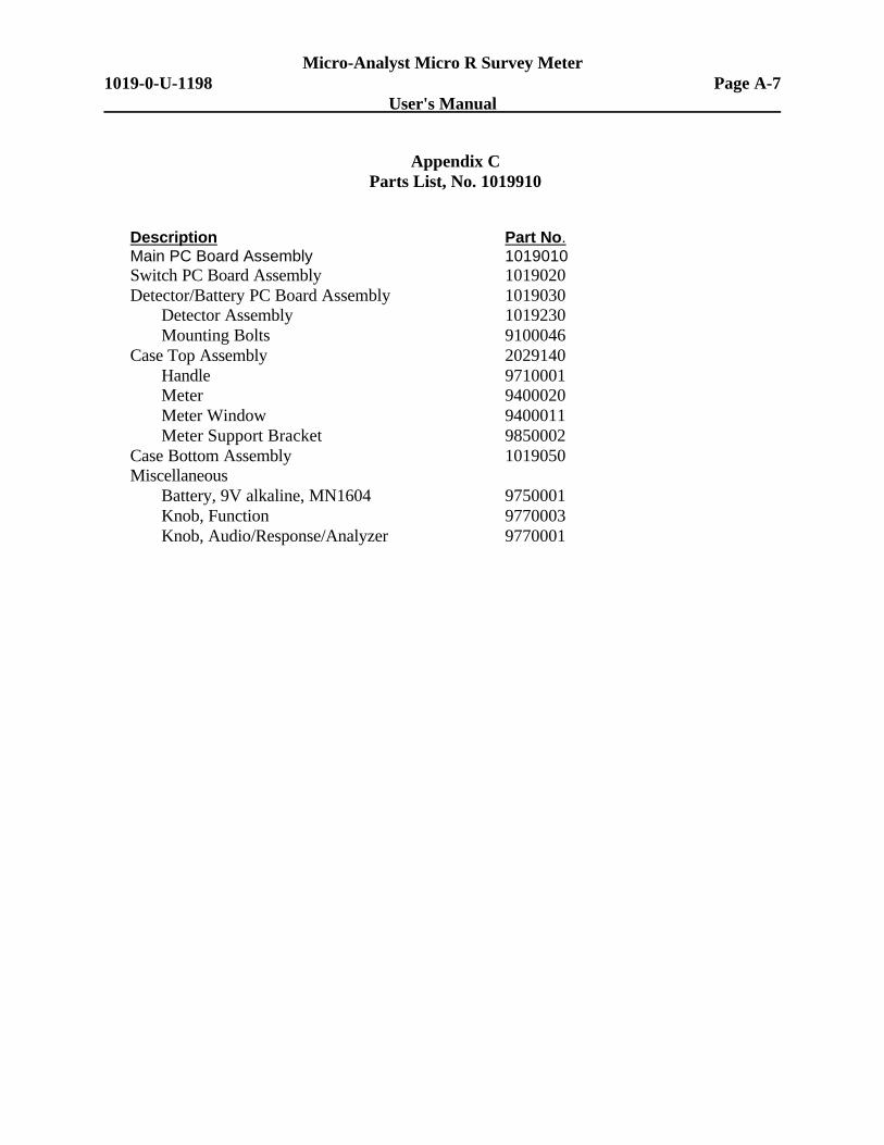
Appendix CParts List, No. 1019910
Description Part No.Main PC Board Assembly 1019010Switch PC Board Assembly 1019020Detector/Battery PC Board Assembly 1019030
Detector Assembly 1019230Mounting Bolts 9100046
Case Top Assembly 2029140Handle 9710001Meter 9400020Meter Window 9400011Meter Support Bracket 9850002
Case Bottom Assembly 1019050Miscellaneous
Battery, 9V alkaline, MN1604 9750001Knob, Function 9770003Knob, Audio/Response/Analyzer 9770001

Micro-Analyst Micro R Survey MeterPage A-8 1019-0-U-1198
User's Manual
BLANK PAGE
Micro-Analyst Micro R Survey Meter1019-0-U-1198 Page A-9
User's Manual
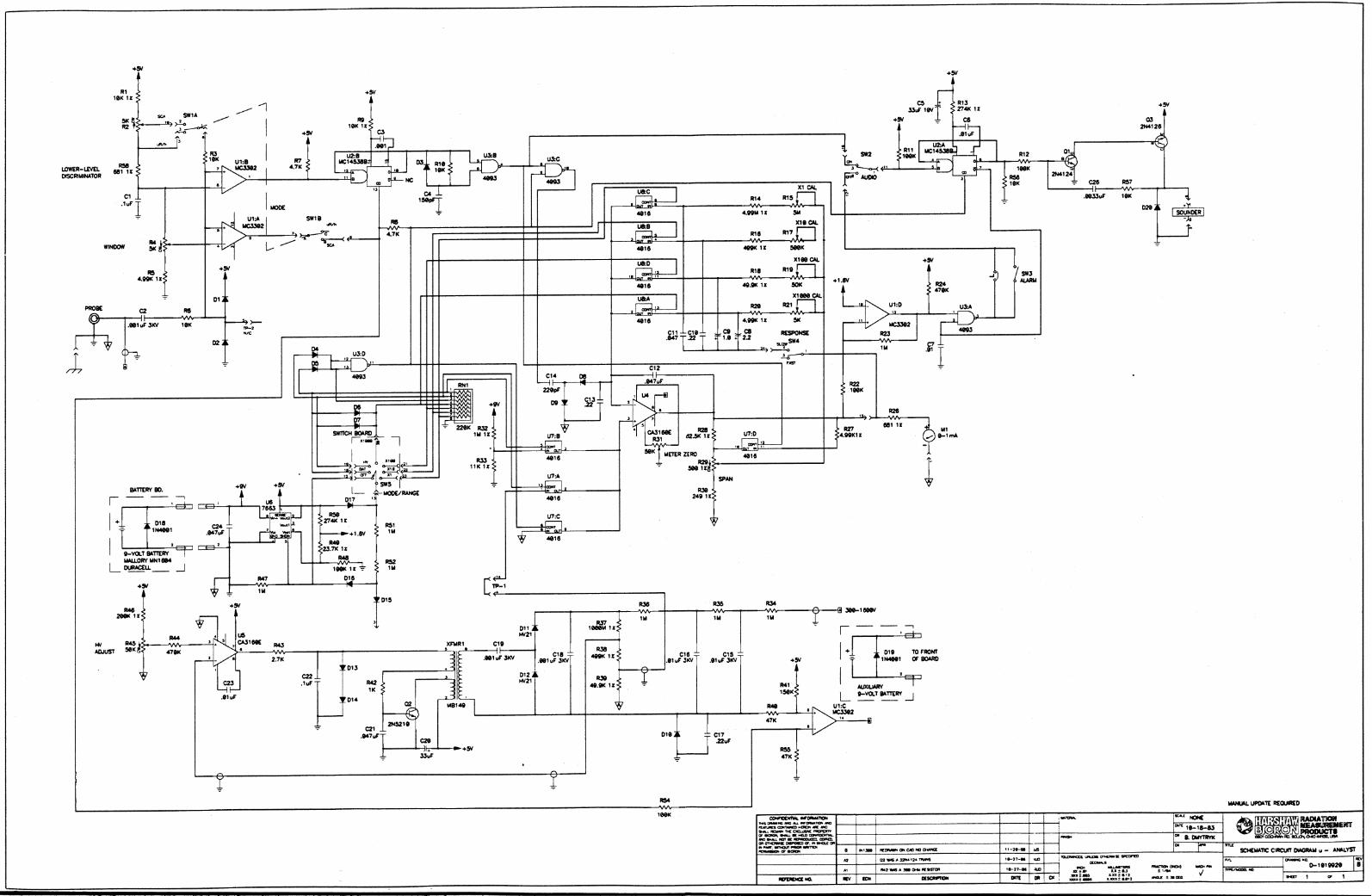
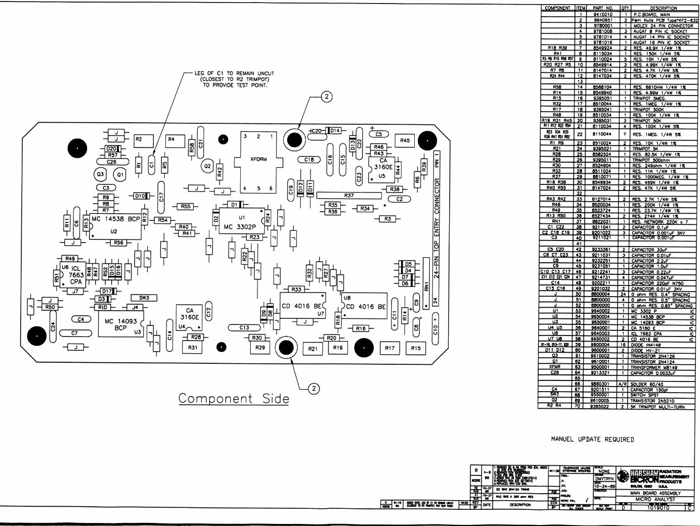
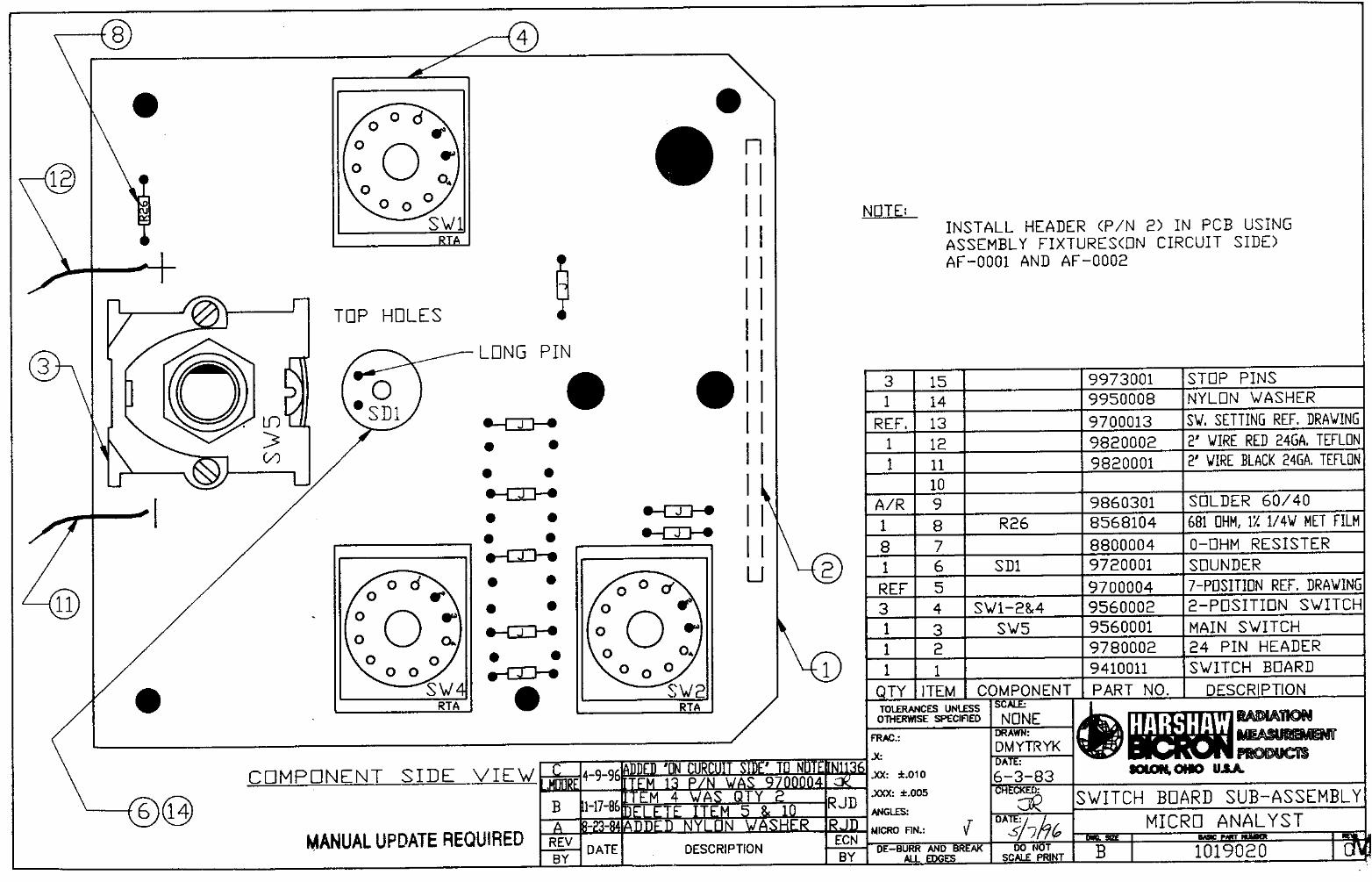
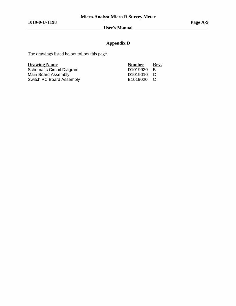
Appendix D
The drawings listed below follow this page.
Drawing Name Number Rev.Schematic Circuit Diagram D1019920 BMain Board Assembly D1019010 CSwitch PC Board Assembly B1019020 C

Micro-Analyst Micro R Survey MeterPage A-10 1019-0-U-1198
User's Manual
BLANK PAGE