Embed Size (px)
Citation preview

8/3/2019 Michigan; Rain Garden Design and Construction - Michigan Technological University
http://slidepdf.com/reader/full/michigan-rain-garden-design-and-construction-michigan-technological-university 1/21
Copyright © Nancy-Jeanne Bachmann, 2006
Rain Garden Design and ConstructionGuidelines
Rooftop runoff capture for homeowners in suburban, urban, and rural areas
By
Nancy-Jeanne BachmannM.S. Candidate
Department of Civil & Environmental EngineeringMichigan Technological University
www.cee.mtu.edu/sustainable_engineering
Prepared for:CE5993: Field Engineering in the Developing World

8/3/2019 Michigan; Rain Garden Design and Construction - Michigan Technological University
http://slidepdf.com/reader/full/michigan-rain-garden-design-and-construction-michigan-technological-university 2/21
Rain Garden Design and Construction Guidelines 2
TABLE OF CONTENTS
1 Introduction..................................................................................................................41.2 Defined..................................................................................................................41.3 Need/Application................................................................................................... 4
2 Tools and Materials List............................................................................................... 63 Site Selection ............................................................................................................... 6
3.1 Physical Rationale ................................................................................................. 63.2 Design...................................................................................................................6
4 Infiltration Media ......................................................................................................... 64.1 Physical Rationale ................................................................................................. 64.2 Design...................................................................................................................7
4.2.1 Volume of Infiltration Media .......................................................................... 85 Vegetation....................................................................................................................8
5.1 Physical Rationale ................................................................................................. 85.2 Design...................................................................................................................9
6 Sizing......................................................................................................................... 10
6.1 Physical Rationale ............................................................................................... 106.2 Design.................................................................................................................116.3 Design Assumptions ............................................................................................ 12
7 Construction............................................................................................................... 127.1 Excavation...........................................................................................................127.2 Berm ................................................................................................................... 137.3 Backfill and Compaction of Bioretention Soil...................................................... 137.4 Planting...............................................................................................................137.5 Mulch..................................................................................................................137.6 Piping to Rain Garden ......................................................................................... 13
8 Design Variations.......................................................................................................14
8.1 On-Site Location ................................................................................................. 148.2 On-Site Soil Infiltration Capacity .........................................................................148.3 Alternative Design Objectives ............................................................................. 14
9 Maintenance............................................................................................................... 199.1 Vegetation...........................................................................................................192.2 Clogging Prevention............................................................................................ 19
10 Final Remarks .......................................................................................................... 1911 Resources................................................................................................................. 20

8/3/2019 Michigan; Rain Garden Design and Construction - Michigan Technological University
http://slidepdf.com/reader/full/michigan-rain-garden-design-and-construction-michigan-technological-university 3/21
Rain Garden Design and Construction Guidelines 3
LIST OF FIGURES
Figure 1 Typical rain garden capturing rooftop runoff from the downspout. This phototaken by Roger Bannerman in Dane County, Wisconsin (WDNR, 2002)......................... 4
Figure 2 Example rain garden sizes, shapes, and positioning for a homeowner’s rooftoprunoff. The three areas darkened in black are the rain gardens; dashed lines below eachgarden indicate relative depth. (PGCM, 2006)................................................................. 5Figure 5 Root Systems of Prairie Plants as diagrammed by Heidi Natura demonstratingthe proportional length of various native prairie plants and turf grass (far left) (1995).The longest roots shown are 15 feet long. ........................................................................ 9Figure 6 Demonstration of a curb cut for runoff capture from street. This picture is froma project in Burnsville, MN, designed by Barr Engineering Company (2004). ............... 14Figure 7 Infiltration and recharge facility for enhanced infiltration designed by PrinceGeorge’s County, MD (2006)........................................................................................ 15Figure 8 Filtration and partial recharge facility designed by Prince George’s County, MD
(2006). .......................................................................................................................... 16Figure 9 Infiltration, filtration, and recharge facility designed by Prince George’s County,MD (2006). ................................................................................................................... 16Figure 10 A filtration-only bioretention cell designed by Prince George’s County, MD(2006). .......................................................................................................................... 17Figure 11 Sizing of a bioretention cell designed by Prince George’s County, MD (2006),shown for comparison to the LID Center design. ........................................................... 18Figure 12 Sizing and specifications of a bioretention cell designed by the LID Center (USEPA, 2003). ............................................................................................................ 18
LIST OF TABLES
Table 1 Plant list for rain gardens with silt and sandy soils in the southern Wisconsinregion provided by Applied Ecological Services, Inc., Brodhead, WI, and published inthe Wisconsin DNR’s Rain Gardens: A how-to manual for homeowners (2003)............10
8/3/2019 Michigan; Rain Garden Design and Construction - Michigan Technological University
http://slidepdf.com/reader/full/michigan-rain-garden-design-and-construction-michigan-technological-university 4/21
Rain Garden Design and Construction Guidelines 4
1 Introduction
Low Impact Development (LID) is an ecologically sensitive design approach tostormwater management. Prince George’s County Department of EnvironmentalResources, a pioneer in LID design and implementation, has developed a heavily
referenced Low Impact Development Design Manual . The manual identifies the goal of LID design to maximize onsite storage and infiltration at the parcel level (PGCM, 1997).Bioinfiltration cells, rain gardens in the vernacular, are a rising component of LID designin suburban and, in some cases, urban United States. Bioinfiltration of stormwater issource control mitigation of overburdened storm sewers. Additional benefits includemaintaining the natural hydrologic regime and restoring elements of lost ecologicalsystems. To date, most designs strive to accept a certain initial depth of any storm,sometimes called the ‘first flush’ (Traver, 2004).
1.2 Defined
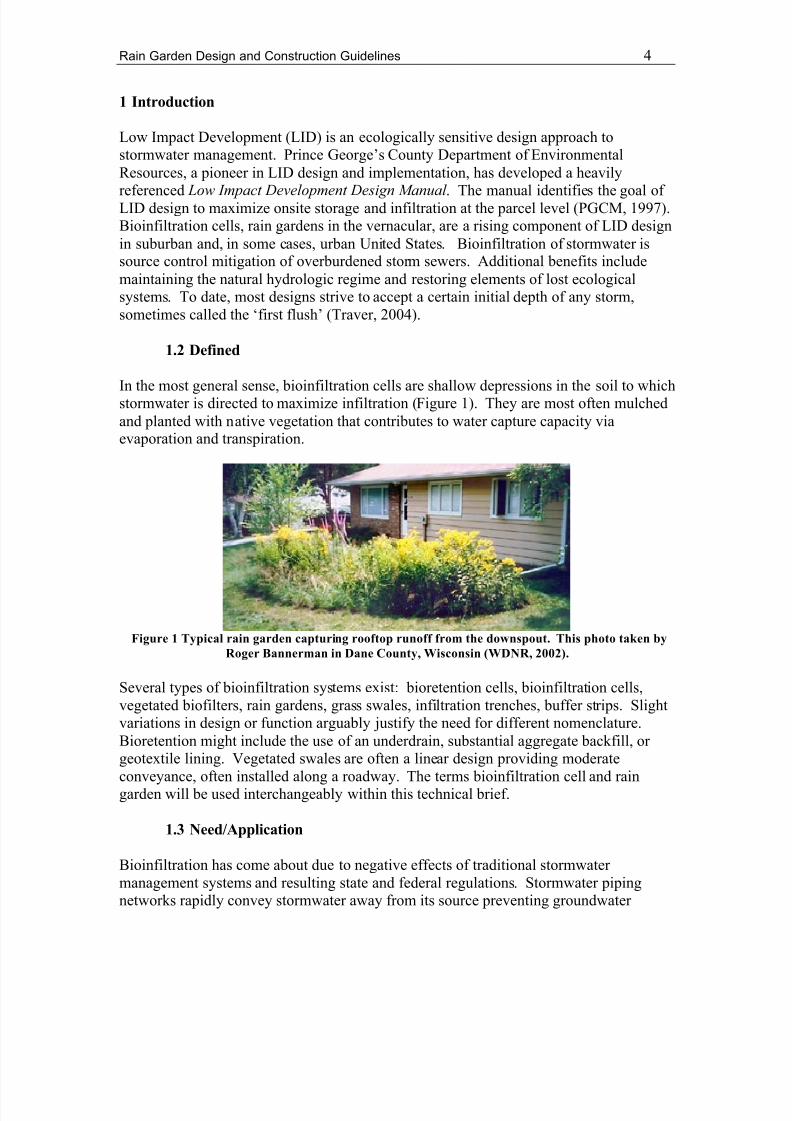
In the most general sense, bioinfiltration cells are shallow depressions in the soil to whichstormwater is directed to maximize infiltration (Figure 1). They are most often mulchedand planted with native vegetation that contributes to water capture capacity viaevaporation and transpiration.
Figure 1 Typical rain garden capturing rooftop runoff from the downspout. This photo taken byRoger Bannerman in Dane County, Wisconsin (WDNR, 2002).
Several types of bioinfiltration systems exist: bioretention cells, bioinfiltration cells,vegetated biofilters, rain gardens, grass swales, infiltration trenches, buffer strips. Slightvariations in design or function arguably justify the need for different nomenclature.Bioretention might include the use of an underdrain, substantial aggregate backfill, or geotextile lining. Vegetated swales are often a linear design providing moderateconveyance, often installed along a roadway. The terms bioinfiltration cell and raingarden will be used interchangeably within this technical brief.
1.3 Need/Application
Bioinfiltration has come about due to negative effects of traditional stormwater management systems and resulting state and federal regulations. Stormwater pipingnetworks rapidly convey stormwater away from its source preventing groundwater
8/3/2019 Michigan; Rain Garden Design and Construction - Michigan Technological University
http://slidepdf.com/reader/full/michigan-rain-garden-design-and-construction-michigan-technological-university 5/21
Rain Garden Design and Construction Guidelines 5
recharge and potentially causing flooding, erosion, and combined sewer overflowsdownstream. Traditional detention basins are not designed for volume reduction, andEmerson et al. (2005) found only a 0.3% watershed-wide reduction in peak storm flowaccording to the modeling of 100 detention basins. Studies like this demonstrate the needto address runoff through source control.
The leading regulation driving site-scale, source control stormwater management is therecent addition of Phase II of the National Pollutant Discharge Elimination System(NPDES) to the 1972 Clean Water Act. It requires small municipalities with separatestorm sewer systems (MS4s) to address stormwater runoff from their site with therecommended use of “structural BMPs [Best Management Practices] such as grassedswales or porous pavement” (USEPA, 2000).
Rooftop runoff, in particular, can be a substantial contributor to municipal storm sewer systems. Pitt et al. (2002) identified one case where directly connected residential roofsconstitute an estimated 30-35% of annual runoff volume in the cities of Phoenix, Seattle
and Birmingham. Runoff source control by homeowners can be valuable to the overallgoal of stormwater runoff and pollution reduction.
1.4 Report Contents
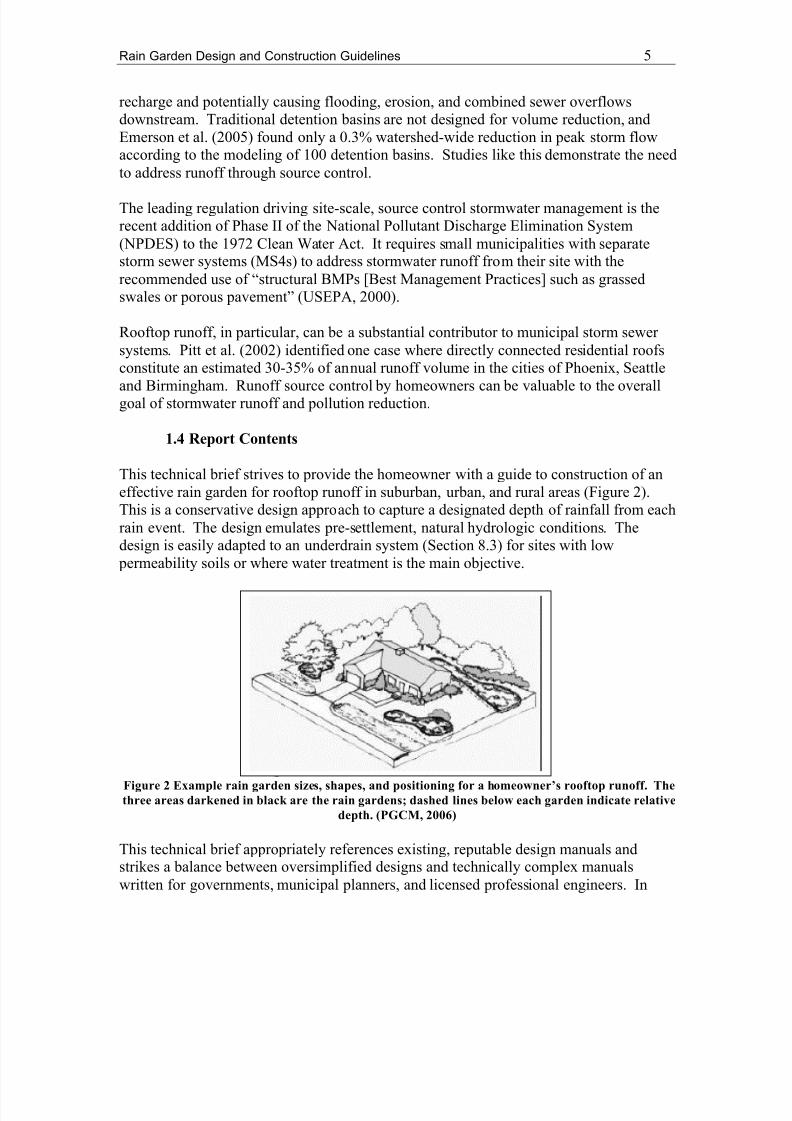
This technical brief strives to provide the homeowner with a guide to construction of aneffective rain garden for rooftop runoff in suburban, urban, and rural areas (Figure 2).This is a conservative design approach to capture a designated depth of rainfall from eachrain event. The design emulates pre-settlement, natural hydrologic conditions. Thedesign is easily adapted to an underdrain system (Section 8.3) for sites with low
permeability soils or where water treatment is the main objective.
Figure 2 Example rain garden sizes, shapes, and positioning for a homeowner’s rooftop runoff. Thethree areas darkened in black are the rain gardens; dashed lines below each garden indicate relative
depth. (PGCM, 2006)
This technical brief appropriately references existing, reputable design manuals andstrikes a balance between oversimplified designs and technically complex manualswritten for governments, municipal planners, and licensed professional engineers. In

8/3/2019 Michigan; Rain Garden Design and Construction - Michigan Technological University
http://slidepdf.com/reader/full/michigan-rain-garden-design-and-construction-michigan-technological-university 6/21
Rain Garden Design and Construction Guidelines 6
particular, it strives to incorporate the most recent design recommendations from research published in the scientific literature.
2 Tools and Materials List
The following list describes the materials needed for the installation of a rain gardendesigned using this manual. Characteristics and quantities of certain materials are further specified in related sections.
• Shovel or optional compact excavator (Section 7)• ~50/50 sand / soil mixture, soil consisting of a sandy loam or silt (Section 4)• Optional soil specific to planted vegetation (Section 4)• Mulch (Section 4)• Additional fine sand (Section 4)• Additional soil (Section 4)• A level (Section 7)• Native mesic plants (Section 5)
3 Site Selection
3.1 Physical Rationale
An ideal site will aid conveyance to the system and contribute to the hydrologic needs(though minimal) of the vegetation during dry periods.
3.2 Design
Select a site at least 10 feet from the foundation of the house to prevent water seepage
into the foundation (WDNR, 2003). Select a site with a gentle downward slope (but lessthan 12%) leading away from the house and into the garden, if possible (WDNR, 2003).Determine whether you will pipe the water from the gutter and pipe directly into thegarden or whether the water will flow over land before reaching the rain garden. Thisdecision will influence the amount of pipe needed (contributing to the cost), and,therefore, the distance from the house.
4 Infiltration Media
4.1 Physical Rationale
Soils in urban settings get compacted during site construction. Soil compactionsignificantly reduces infiltration rates compared to native soils. For example, Pitt et al.(2002) compared infiltration rates of non-compacted and compacted sandy soils andobtained a reduction from 13 in/hr to 1.4 in/hr due to compaction. For this reason, a non-compacted, moderate to high infiltration media will backfill the bioinfiltration cell. This

8/3/2019 Michigan; Rain Garden Design and Construction - Michigan Technological University
http://slidepdf.com/reader/full/michigan-rain-garden-design-and-construction-michigan-technological-university 7/21
Rain Garden Design and Construction Guidelines 7
media also provides water treatment through sedimentation, filtration, sorption 1, and precipitation 2 (Hseih and Davis, 2005). Settling occurs in the shallow ponding area,filtering occurs through the layers of media, adsorption 3 and cation exchange 4 occur within the biologically active organic materials in the filter, and phytoremediation 5 occurs
by the plants (Clar et al., 2004: PGCM, 2006). Total suspended solids (TSS) in the water
entering the rain garden are filtered out in this design. TSS are a concern because theycan promote clogging of the media, restricting the hydraulic conductivity 6 and rate of infiltration (Beach et al., 2005).
It is important to obtain and retain a high enough infiltration rate that the rain gardendrains before mosquitoes are able to propagate. They require 7 – 12 days to lay and hatcheggs (WDNR, 2003). The USEPA recommends a conservative drainage time of 48 hoursor less to prevent propagation of mosquitoes (1999). This constraint is also satisfied inthe design.
4.2 Design
Hseih and Davis (2005) recommend two possibilities for optimum water treatment. Dueto ASCE copyright, they may not be copied here but are accessible athttp://scitation.aip.org/getabs/servlet/GetabsServlet?prog=normal&id=JOEEDU000131000011001521000001&idtype=cvips&gifs=yes or http://scitation.aip.org/getpdf/servlet/GetPDFServlet?filetype=pdf&id=JOEEDU000131000011001521000001&idtype=cvips&prog=normal if access is approved or on page 1530,Figures 4a and 4b of the referenced journal publication. In this technical brief, thedesigns will be referred to as Hseih and Davis (2005) Figures 4a and 4b.
In both designs, the mulch layer should be of high permeability (d 107>0.1mm, 0.00039in)
and appropriate uniformity (a d 60/d10 value less than 4) to filter TSS (Hseih and Davis,2005).
Hseih and Davis Figure 4a demonstrates a single-layer media design for maximum water quality treatment consisting of 20-70% sandy soil (sandy loam texture) mixed with coarsesand (e.g. d 10>0.3mm). Plant species requirements will inform the chosen percentage.The suggested depth is 55-75 cm for best water quality treatment. Infiltration rates were
1 Sorption includes several processes through which solutions (e.g. water and chemical constituents) bind tosolids including absorption and adsorption.2
The precipitation of chemical constituents is the separation of the constituent from solution as a solid.3 Adsorption is the process at the solution-soil interface in which the soil attracts and holds to its surface asolution.4 Cation exchange is the switching places of cations (positively charged ions) in solution with cationsadsorbed to the soil.5 Phytoremediation is the neutralization or removal of chemical constituents through vegetation.6 Hydraulic conductivity is a measure of the soil’s ability to transmit water. This varies with respect to soilmoisture content and pore water pressure.7 The designation d x represents the diameter of particles in an aggregate for which at least x percent are thatdiameter or finer. This number can be provided by the supplier.

8/3/2019 Michigan; Rain Garden Design and Construction - Michigan Technological University
http://slidepdf.com/reader/full/michigan-rain-garden-design-and-construction-michigan-technological-university 8/21
Rain Garden Design and Construction Guidelines 8
found to be between 1.2 – 5.4 cm/min at 15 cm water head 8. This design requiresminimal construction and maintenance as compared to the design in Hseih and DavisFigure 4b.
Hseih and Davis (2005) Figure 4b illustrates a multilayer design for maximum water
quality treatment that incorporates a vegetation layer for optimum plant survival and afilter layer for treatment. The filter layer serves as a back-up to the initial vegetationlayer. The vegetation layer (25 – 30 cm in depth) is specific to the region of installation.Consult a local naturalist or plant nursery for guidance as you obtain from them the
plants. The filter layer consists of the same coarse sand (e.g. d 10>0.3mm) and sandy loamsoil as recommended in the single layer design, but existing in a 50/50 sand/soil ratio inthis case. The Hseih and Davis (2005) Figure 4b design requires more construction andmaintenance than the single layer design (Hseih and Davis (2005) Figure 4a).
In the latter design, total phosphorus, nitrate, and ammonium removal is expected to begreater by about 50%, 3%, and 9%, respectively (Hseih and Davis, 2005). This relative,
additional treatment can be weighed against increased design complexity to inform your decision about which design to install.
4.2.1 Volume of Infiltration Media
In order to account for minor compaction during construction, obtain 10% more materialthan that required according to the diagram’s dimensions.
5 Vegetation
5.1 Physical Rationale
In general, vegetation helps to maintain the infiltration capacity of the bioretention cellmedia (Clar et al. 2004). Bioretention plants are also a component of water treatment
because they can uptake some nutrients and heavy metals from the media (Hsieh andDavis, 2005). This is referred to as phytoremediation.
In general, native plants are preferred over nonnative plants due to their adaptation to theregional climatic trends. The author’s experience comes from the Midwest where mesic 9
prairie species are the plants of choice for rain gardens. Prairie species demonstrate theadaptive nature of plants to their native regions.
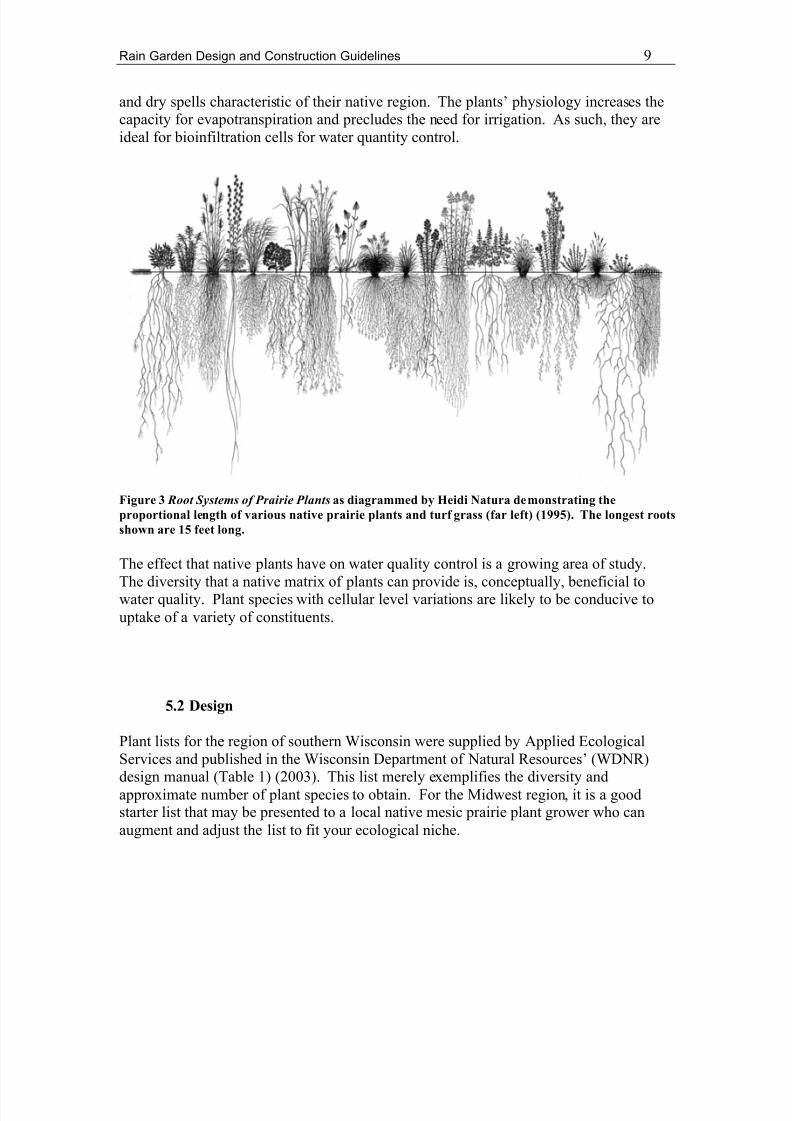
Figure 3 demonstrates the proportional root depth of a variety of native prairie species ascompared to turf grass (far left in the diagram). The longest roots shown are 15 feet long.Long roots and large root masses enable the plants to locate water in periods of drought,long after the turf grass has wilted. The plants are adapted to the trends of rain storms
8 Water head refers to the height of water above the point of interest. Due to gravity, water head increasesthe downward force of water moving into the soil.9 The term mesic is a designation for an ecosystem’s level of dryness. It falls in the middle of wet and dry(e.g. in decreasing order of average soil moisture content - wet prairie, mesic prairie, and dry prairie).
8/3/2019 Michigan; Rain Garden Design and Construction - Michigan Technological University
http://slidepdf.com/reader/full/michigan-rain-garden-design-and-construction-michigan-technological-university 9/21
Rain Garden Design and Construction Guidelines 9
and dry spells characteristic of their native region. The plants’ physiology increases thecapacity for evapotranspiration and precludes the need for irrigation. As such, they areideal for bioinfiltration cells for water quantity control.
Figure 3 Root Systems of Prairie Plants as diagrammed by Heidi Natura demonstrating theproportional length of various native prairie plants and turf grass (far left) (1995). The longest rootsshown are 15 feet long.
The effect that native plants have on water quality control is a growing area of study.
The diversity that a native matrix of plants can provide is, conceptually, beneficial towater quality. Plant species with cellular level variations are likely to be conducive touptake of a variety of constituents.
5.2 Design
Plant lists for the region of southern Wisconsin were supplied by Applied EcologicalServices and published in the Wisconsin Department of Natural Resources’ (WDNR)design manual (Table 1) (2003). This list merely exemplifies the diversity andapproximate number of plant species to obtain. For the Midwest region, it is a goodstarter list that may be presented to a local native mesic prairie plant grower who canaugment and adjust the list to fit your ecological niche.
8/3/2019 Michigan; Rain Garden Design and Construction - Michigan Technological University
http://slidepdf.com/reader/full/michigan-rain-garden-design-and-construction-michigan-technological-university 10/21
Rain Garden Design and Construction Guidelines 10
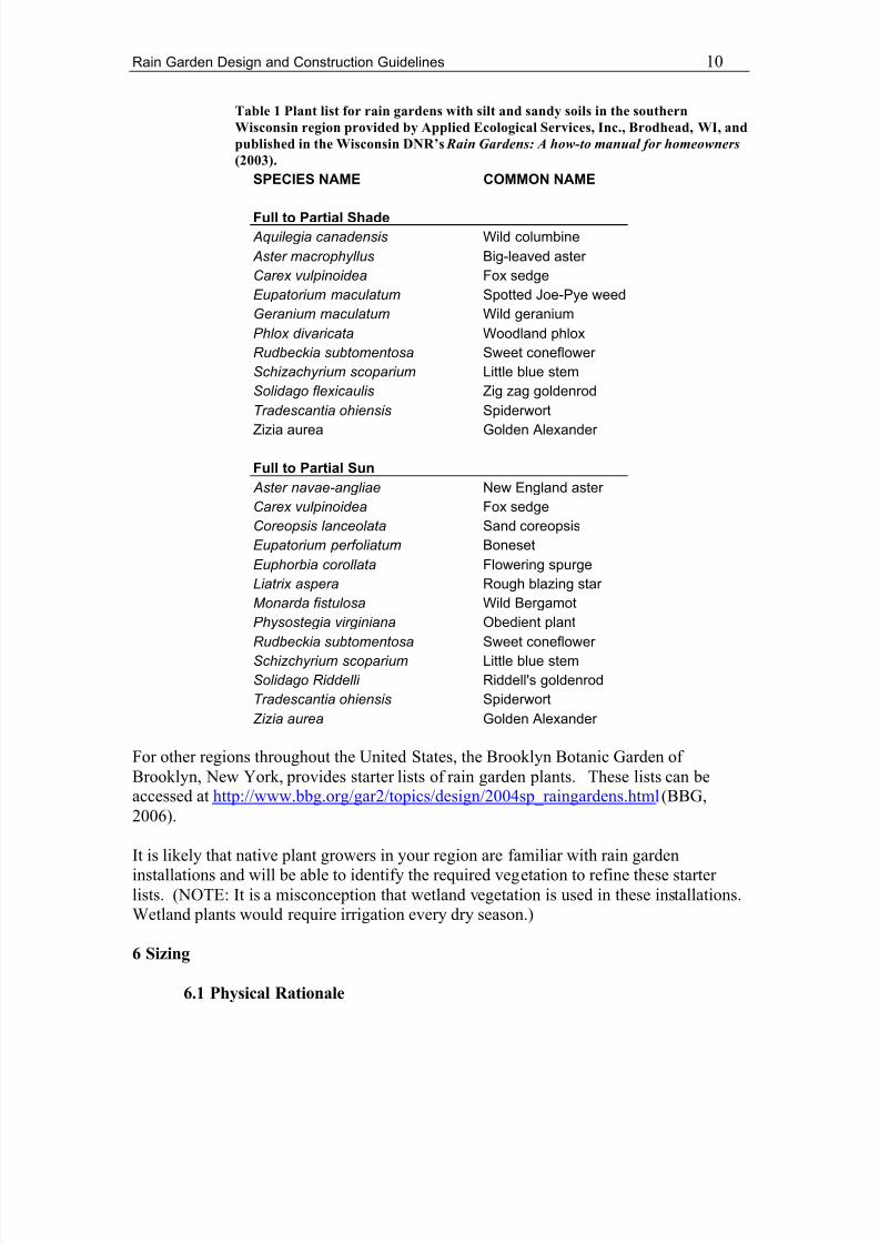
Table 1 Plant list for rain gardens with silt and sandy soils in the southernWisconsin region provided by Applied Ecological Services, Inc., Brodhead, WI, andpublished in the Wisconsin DNR’s Rain Gardens: A how-to manual for homeowners (2003).
SPECIES NAME COMMON NAME
Full to Partial Shade Aquilegia canadensis Wild columbine Aster macrophyllus Big-leaved aster Carex vulpinoidea Fox sedgeEupatorium maculatum Spotted Joe-Pye weedGeranium maculatum Wild geraniumPhlox divaricata Woodland phloxRudbeckia subtomentosa Sweet coneflower Schizachyrium scoparium Little blue stemSolidago flexicaulis Zig zag goldenrodTradescantia ohiensis Spiderwort
Zizia aurea Golden Alexander
Full to Partial Sun Aster navae-angliae New England aster Carex vulpinoidea Fox sedgeCoreopsis lanceolata Sand coreopsisEupatorium perfoliatum BonesetEuphorbia corollata Flowering spurgeLiatrix aspera Rough blazing star Monarda fistulosa Wild BergamotPhysostegia virginiana Obedient plantRudbeckia subtomentosa Sweet coneflower Schizchyrium scoparium Little blue stemSolidago Riddelli Riddell's goldenrodTradescantia ohiensis SpiderwortZizia aurea Golden Alexander
For other regions throughout the United States, the Brooklyn Botanic Garden of Brooklyn, New York, provides starter lists of rain garden plants. These lists can beaccessed at http://www.bbg.org/gar2/topics/design/2004sp_raingardens.html (BBG,2006).
It is likely that native plant growers in your region are familiar with rain gardeninstallations and will be able to identify the required vegetation to refine these starter lists. (NOTE: It is a misconception that wetland vegetation is used in these installations.Wetland plants would require irrigation every dry season.)
6 Sizing
6.1 Physical Rationale

8/3/2019 Michigan; Rain Garden Design and Construction - Michigan Technological University
http://slidepdf.com/reader/full/michigan-rain-garden-design-and-construction-michigan-technological-university 11/21
Rain Garden Design and Construction Guidelines 11
An underdrained swale system with backfill similar to a bioretention cell provides insightinto critical characteristics that influence reduction of runoff, storage, and infiltration.Effectiveness depends on the size of the bioretention cell in addition to other contributingfactors. The reduction in runoff will depend on the temporal distribution of runoff contributions to the rain garden and the ability of the soil to infiltrate water. The storage
and infiltration will also depend largely on the intensity of the storm and the inflow(Barber et al., 2003). The infiltration rates influencing runoff reduction and storage havealready been addressed (Sections 4 and 5). This section addresses the sizing.
The sizing method used here is a conservative calculation. It is sized to have anaboveground storage capacity equivalent to a determined depth of runoff from the roof area. This design was used by Dietz and Clausen (2006) in a reputable study on raingarden flow and pollutant retention. These authors found it to be compatible with the1993 version of The Bioretention Manual developed by Prince George’s County, MD(1993). The updated manual continues to be the most referenced manual and a leader internationally in LID design methods (PGCM, 2006). It utilizes the Natural Resource
Conservation Service Curve Number to account for sites with variable land-use. Thedesign discussed here assumes one surface type, the rooftop, and allows for simplifiedcalculations suited to the homeowner’s application.
6.2 Design
(1) Determine the depth of rainfall desired for capture. There are a few options for determining this value:
a. At a minimum, you can use a 0.5-inch depth of rainfall which could beconsidered capturing the ‘first-flush’ of the rainfall event. Capturing thefirst-flush is especially important in roadway runoff applications. Inrooftop drainage, areas with considerable atmospheric deposition wouldcause a contaminated first-flush of runoff;
b. Access the National Weather Service’s historic precipitation data from therain gage nearest you. Locate the total depth of each rain storm for the
past several years. From this data determine a constant depth of rainfallfrom each storm that constitutes 80% of the annual runoff. This will beyour desired rainfall capture depth;
c. Or you may wish to maximize the acreage of your rain garden to captureas much rainfall as is feasible on your lawn. In this case, you woulddesign on this basis. If desired, you can back calculate your theoreticalcapture volume.
(2) Calculate the plan view (bird’s eye view) area of the rooftop which will drain intothe bioretention facility. This is easily based on the dimensions of the foundationof the house.
(3) Multiply the plan view area of the roof by the desired rainfall capture depth(based on item (1)) to attain the approximate volume of runoff which the
bioretention cell will need to accept.

8/3/2019 Michigan; Rain Garden Design and Construction - Michigan Technological University
http://slidepdf.com/reader/full/michigan-rain-garden-design-and-construction-michigan-technological-university 12/21
Rain Garden Design and Construction Guidelines 12
(4) Divide by 4 inches the volume of runoff desired for capture. This is the requiredsurface area of your garden. Four inches is determined to be the maximumstorage depth 10 of your garden.
(5) Determine the shape of your rain garden satisfying the calculated surface arearequirements. A good shape is approximately twice as long as it is wide for
optimum distribution of inflow throughout the rain garden. The longestdimension should be oriented perpendicular to the slope.
Using this technique, the intention is that the bioretention cell will infiltrate the desiredvolume of runoff. Excess runoff will overflow and run down the lawn to the storm sewer system as it would have before bioretention cell installation.
6.3 Design Assumptions
This is a conservative design. The design assumes that all of the desired runoff will fillthe basin at one time. In reality, infiltration will occur before the desired depth of
precipitation has fallen and the rain garden’s capacity will be greater than the volume for which it was designed.
The design also makes a reasonable assumption that runoff from the impervious roof ismagnitudes larger than the runoff from the short section of pervious lawn between theroof and the bioretention cell. Runoff from the lawn is considered negligible.
7 Construction
The following guidelines are for the construction of the two Hseih and Davis (2005)diagrams referenced in Section 4 as Figures 4a and 4b. All specifications are provided
below except for those cases where greater detail is provided in previous sections.
7.1 Excavation
Excavate to a depth of 125 cm (49 inches, 4.1 feet) measured from the uphill edge of therain garden. This depth is based on maximum media depths as shown in the Hseih andDavis (2005) diagrams (referenced in Section 4 as Figures 4a and 4b) including 4 inchesof above-ground storage.
Side walls can be close to vertical to maximize the volume of infiltration media backfilland to simplify the calculations of needed materials. (NOTE: Do NOT dig deeper than 5feet without competent personnel trained in excavation safety. In 1993 the U.S.Occupational Safety and Health Administration (OSHA) instituted a law requiring trained
personnel on site and proper protection of trench walls for trenches greater than 5 feetdeep. Protection from collapse includes sheeting/bracing, shoring or sloping. Go tohttp://www.osha.gov for more information.)
10 The native vegetation referred to in Section 5 will limit the pooling depth to around 4 inches for satisfactory growing conditions (WDNR 2003). Consultation with a local supplier may adjust this depth.
8/3/2019 Michigan; Rain Garden Design and Construction - Michigan Technological University
http://slidepdf.com/reader/full/michigan-rain-garden-design-and-construction-michigan-technological-university 13/21

8/3/2019 Michigan; Rain Garden Design and Construction - Michigan Technological University
http://slidepdf.com/reader/full/michigan-rain-garden-design-and-construction-michigan-technological-university 14/21
Rain Garden Design and Construction Guidelines 14
Using flexible, light-weight, corrugated polyethylene pipe, extend the downspout fromcontributing roof areas to the uphill edge of the rain garden perimeter. The piping may
be aligned with room for an extension (a flared end section or an apron) that disperses thewater at the perimeter. If necessary (i.e. erosion occurs at the inlet to the garden), smallcobble may be used at the inlet to dissipate the force of the water entering the rain garden.
8 Design Variations
8.1 On-Site Location
Rain gardens may be located at the end of the yard along the street curb rather than closeto the house. This location has two advantages. Assuming a downward sloping yard, itcan capture more on-site runoff. In addition, curb cuts could be made to accept, infiltrate,and treat stormwater runoff from the road (Figure 4).
Figure 4 Demonstration of a curb cut for runoff capture from street. This picture isfrom a project in Burnsville, MN, designed by Barr Engineering Company (2004).
For a successful case study of an entire neighborhood’s project and explanatory pictures,see Barr Engineering Company’s installation in Burnsville, MN, as documented in Land
and Water magazine (2004) available at www.landandwater.com.
8.2 On-Site Soil Infiltration Capacity
Two simple, low-technology tests may be performed to determine pre-constructioninfiltration rates (refer to page 9 of the manual mentioned in this section). If on-site soilshave infiltration rates greater than 0.5 in/hr you can design and build the rain gardenaccording to the Wisconsin Department of Natural Resources’ manual, Rain Gardens: A
How-to Manual for Homeowners (WDNR, 2003). This manual involves minimalexcavation, is user friendly, and is commonly referenced among Midwestern, non-profitorganizations that encourage these installations. It is available online athttp://www.dnr.state.wi.us/org/water/wm/nps/rg/index.htm .
8.3 Alternative Design Objectives
8/3/2019 Michigan; Rain Garden Design and Construction - Michigan Technological University
http://slidepdf.com/reader/full/michigan-rain-garden-design-and-construction-michigan-technological-university 15/21
Rain Garden Design and Construction Guidelines 15
If water quality treatment is prioritized over infiltration and groundwater recharge, anunderdrain approach is becoming the standard. The drain pipe allows water to beconveyed through the system when infiltration below and surrounding the cell is too slow(Barber et al., 2003).
Below is a collection of cross sections and descriptions delineating variations on thedesign and their respective functions. In all cases (except for the first), the designincorporates a perforated pipe for the underdrain, a cleanout/observation well 11, coarseaggregate, and an optional geotextile covering the entire excavated perimeter or some
portion of it. Construction may be done independently or with on-site technical aid.Specifications suitable for a contractor or regulatory approval (if, in the rare case,connecting to a storm sewer) may be required. In all cases, the underdrain system isexpected to limit ponding to less than half an hour (PGCM, 2006). All pictures andsummarized descriptions are drawn from the Bioretention Manual developed by PrinceGeorge’s County, MD (2006).
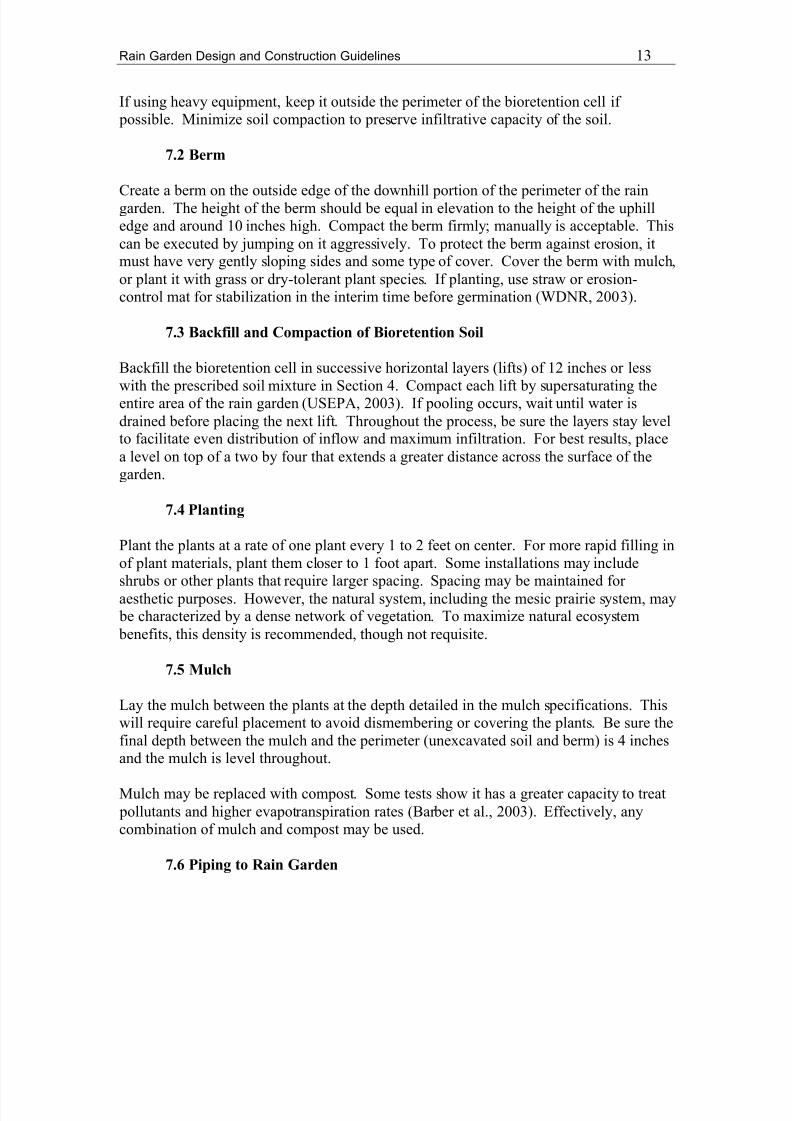
The bioretention cell design in Figure 5 facilitates high recharge of groundwater. Themanual recommends in-situ soils with infiltration rates of at least 1 in/hr and a depth of atleast 2.5 feet for adequate filtration.
Figure 5 Infiltration and recharge facility for enhanced infiltration designed by Prince George’sCounty, MD (2006).
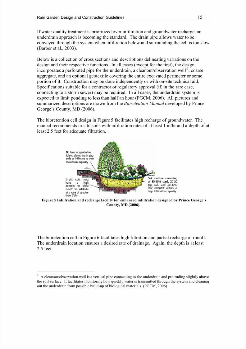
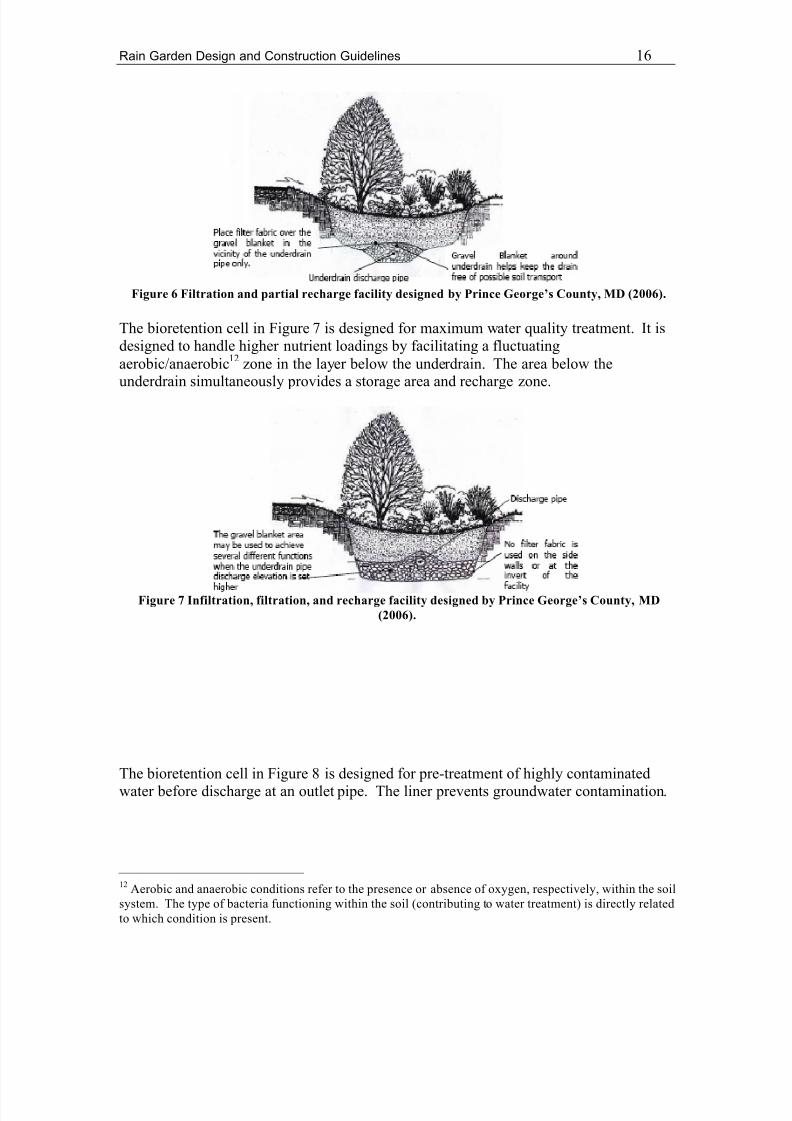
The bioretention cell in Figure 6 facilitates high filtration and partial recharge of runoff.
The underdrain location ensures a desired rate of drainage. Again, the depth is at least2.5 feet.
11 A cleanout/observation well is a vertical pipe connecting to the underdrain and protruding slightly abovethe soil surface. It facilitates monitoring how quickly water is transmitted through the system and cleaningout the underdrain from possible build-up of biological materials. (PGCM, 2006)
8/3/2019 Michigan; Rain Garden Design and Construction - Michigan Technological University
http://slidepdf.com/reader/full/michigan-rain-garden-design-and-construction-michigan-technological-university 16/21
Rain Garden Design and Construction Guidelines 16
Figure 6 Filtration and partial recharge facility designed by Prince George’s County, MD (2006).
The bioretention cell in Figure 7 is designed for maximum water quality treatment. It isdesigned to handle higher nutrient loadings by facilitating a fluctuatingaerobic/anaerobic 12 zone in the layer below the underdrain. The area below theunderdrain simultaneously provides a storage area and recharge zone.
Figure 7 Infiltration, filtration, and recharge facility designed by Prince George’s County, MD(2006).
The bioretention cell in Figure 8 is designed for pre-treatment of highly contaminatedwater before discharge at an outlet pipe. The liner prevents groundwater contamination.
12 Aerobic and anaerobic conditions refer to the presence or absence of oxygen, respectively, within the soilsystem. The type of bacteria functioning within the soil (contributing to water treatment) is directly relatedto which condition is present.

8/3/2019 Michigan; Rain Garden Design and Construction - Michigan Technological University
http://slidepdf.com/reader/full/michigan-rain-garden-design-and-construction-michigan-technological-university 17/21
Rain Garden Design and Construction Guidelines 17
Figure 8 A filtration-only bioretention cell designed by Prince George’s County, MD (2006).
The Department of Environmental Resources of Prince George’s County, MD, hasdeveloped a comprehensive guide (from which the above diagrams and descriptionsoriginated) to understanding and designing a bioretention system that utilizes anunderdrain. The design criteria and conditions are specified for implementation in a
residential community. The manual provides complete instruction and examples on howto develop the bioretention plans as well as a corresponding grading plan and sedimentand erosion control plan. The document identifies issues and responsibilities for thehomeowner, developer, designer, and inspector from the concept phase through themaintenance and operation phases of the bioretention cell installation. It also includesguidance for construction, community involvement, maintenance, and additional notes oncompaction. It is available on the County’s website athttp://www.co.pg.md.us/Government/AgencyIndex/DER/ESD/Bioretention/bioretention.asp.
For purposes of comparison to the design recommended in this technical brief, Figure 9 isa cross section delineating basic dimensions as recommended by Prince George’sCounty. The two designs are comparable in this regard.

8/3/2019 Michigan; Rain Garden Design and Construction - Michigan Technological University
http://slidepdf.com/reader/full/michigan-rain-garden-design-and-construction-michigan-technological-university 18/21
Rain Garden Design and Construction Guidelines 18
Figure 9 Sizing of a bioretention cell designed by Prince George’s County, MD (2006), shown forcomparison to the LID Center design.
An additional set of bioretention cell specifications is notable. The non-profit, LowImpact Development Center in Beltsville, MD, has posted on its website a bioretentionspecification developed through a Cooperative Assistance Agreement under the US EPAOffice of Water 104b(3) Program. It is developed for “local governments, planners, andengineers for developing, administering, and incorporating Low Impact Development(LID) into their aquatic resource protection programs” (USEPA, 2003). Figure 10 is the
plan designed for the application discussed here. The specifications can be found onlineat http://www.lowimpactdevelopment.org/epa03/biospec.htm .
Figure 10 Sizing and specifications of a bioretention cell designed by the LID Center (USEPA, 2003).
NOTE: If installing an underdrain according to these design variations, the infiltrationmedia diagrammed in Hseih and Davis (2005) diagrams (referenced in Section 4 as

8/3/2019 Michigan; Rain Garden Design and Construction - Michigan Technological University
http://slidepdf.com/reader/full/michigan-rain-garden-design-and-construction-michigan-technological-university 19/21
Rain Garden Design and Construction Guidelines 19
Figures 4a and 4b) can be a more specific designation of the ‘bioretention soil’ asdiagrammed in the underdrain cross section (Figure 10).
9 Maintenance
9.1 Vegetation
In its first 2-3 years of growth, required maintenance will be intensive with regard to thevegetation. Until a dense network of vegetation is established, weeding non-natives andespecially invasive 13 plants will be a necessity. Mulch will help prevent weeds but maysimultaneously stall expansion of the planted vegetation. Once the matrix is established,it will be an effective defense against the germination of invasives (Vanderpoel, 2003).Smaller rain gardens can be hand-weeded. Spot herbicide application using state-approved chemicals is an option for treatment. In the case of herbicide application, itshould be used sparingly and in dry, calm conditions only. At no point shouldapplication occur in standing water. In the case of wind, drift from the spray may stunt
the growth of (or kill) downwind plants.2.2 Clogging Prevention
The rain garden should increase in infiltrative capacity during the initial establishment of the root network of the plants due to the resulting organics in the soil and the increasedtranspiration. However, rain gardens may be susceptible to clogging after a certain
period of time, dependent upon the contaminant and solids loading. An option to restorethe infiltrative capacity and break up the biomat 14 may be to aerate and loosen up the soilannually. This must be done without uprooting or disturbing the plants. In the dormantseason, piercing the soil with a pitch fork in the vertical direction (careful not to overturnthe soil) may be the best remedy at the lowest risk of damage. Although untested, it may
be effective to do this with care throughout the growing season.
10 Final Remarks
Adding a rain garden to your property helps to restore the natural hydrology of the area.It reduces contributions to storm sewers, mitigates downstream flooding, and provides anoutlet for education and native ecosystem restoration.
Rain gardens also contribute aesthetically to your property, raising your property value.Prince George’s County, Maryland, has identified properties with rain gardens as havingincreased real estate values by up to 20% (PGCM, 2006). In Prairie Crossingsubdivision, they roughly estimated that their homes command a 30% premium over other typical nearby communities (Prairie Crossing Information and Sales Center, 2006).
13 Invasive plants are characterized by their aggressive propagation and prevention of native plantestablishment. Usually invasives are nonnative and natives are noninvasive. However, this is not alwaysthe case.14 Biomats are formed as a result of biological buildup (or clogging) in a horizontal zone within the soil.

8/3/2019 Michigan; Rain Garden Design and Construction - Michigan Technological University
http://slidepdf.com/reader/full/michigan-rain-garden-design-and-construction-michigan-technological-university 20/21
Rain Garden Design and Construction Guidelines 20
To see a community development utilizing comprehensive Low Impact Developmenttechniques such as rain gardens on a large scale, go to www.prairiecrossing.com .
11 Resources
Barr Engineering Company. (September/October 2004). “Burnsville Rainwater Gardens.” Land and Water , 48(5), 47.
Barber, M. E., King, S. G., Yonge, D. R., Hathorn, W. E. (2003). “Ecology Ditch: A BestManagement Practice for Storm Water Runoff Mitigation.” J. Hydrologic Egrg , 8(3),111.
Beach, D.N.H., McCray, J.E., Lowe, K.S., Siegrist, R.L. (2005). “Temporal Changes inHydraulic Conductivity of Sand Porous Media Biofilters During Wastewater InfiltrationDue to Biomat Formation.” J. Hydrology , 311, 230-243.
Bouwer, H. (2002). “Artificial Recharge of Groundwater: Hydrogeology andEngineering.” Hydrogeology Journal , 10, 121-142.
Brooklyn Botanic Garden (BBG) (2006). “Rain Garden Plants.”http://www.bbg.org/gar2/topics/design/2004sp_raingardens.html Last accessed 12 April 2006.
Christianson, R.D., Barfield, B. J., Hayes, J. C., Gasem, K., Brown, G. O. (2004).“Modeling Effectiveness of Bioretention Cells for Control of Stormwater Quantity andQuality.” ASCE Conf. Proc. , Critical Transitions in Water and Environmental ResourcesManagement , 37.
Clar, M. L., Barfield, B., O’Connor, T. (2004). “BMP Design Guidelines: VegetativeBiofilters.” ASCE Conf. Proc., Critical Transitions in Water and Environmental
Resources Management , 66.
Dietz, M. E., Clausen, J. C. (2006). “Saturation to Improve Pollutant Retention in a RainGarden.” Environmental Science and Technology , 40(4), 1335-1340.
Emerson, C. H., Welty, C., Traver, R. G. (2005). “Watershed-Scale Evaluation of aSystem of Storm Water Detention Basins.” J. Hydrologic Engrg ., 10(3), 237-242.
Hsieh, C-h, Davis, A.P. (2005). “Evaluation and Optimization of Bioretention Media for Treatment of Urban Storm Water Runoff.” J. of Environ. Engrg., 131(11), 1521-1531.
Natura, Heidi. 1995. “Root Systems of Prairie Plants.” Available athttp://www.livinghabitats.com/
Pitt, R., Chen, S-E, Clark, S. (2002). “Compacted Urban Soils Effects on Infiltration andBioretention Stormwater Control Designs.” ASCE Conf. Proc. , Urban Drainage, 14.

8/3/2019 Michigan; Rain Garden Design and Construction - Michigan Technological University
http://slidepdf.com/reader/full/michigan-rain-garden-design-and-construction-michigan-technological-university 21/21
Rain Garden Design and Construction Guidelines 21
Prairie Crossing Information and Sales Center. Email Correspondence. 11 March 2006.
Prince George’s County, Maryland (PGCM), Department of Environmental Resources.The Bioretention Manual ; Watershed Protection Branch, MD Department of
Environmental Protection: Landover, MD, 1993.
Prince George’s County, Maryland (PGCM), Department of Environmental Resources. The Bioretention Manual ; Watershed Protection Branch, MD Department of Environmental Resources: Largo, MD, 2006.Available athttp://www.goprincegeorgescounty.com/government/agencyindex/der/esd/bioretention/bioretention.asp
Prince George’s County, Maryland (PGCM), Department of Environmental Resources.1997. Low Impact Development Design Manual . Prince George’s County, MD.
Traver, R.G. (2004). “Infiltration Strategies for LID.” ASCE Conf. Proc. , World Water Congress, Critical Transitions in Water and Environmental Resources Management, 83.
United States Environmental Protection Agency (USEPA) (2003). Drainage- Bioretention Specification . Cooperative Assistance Agreement, Program 104b(3), Officeof Water. http://www.lowimpactdevelopment.org/epa03/biospec.htm Last accessed 30 March 2006.
United States Environmental Protection Agency (USEPA). (2000, revised 2005).“Stormwater Phase II Final Rule: Small MS4 Stormwater Program Overview.”http://www.epa.gov/npdes/pubs/fact2-0.pdf Last accessed 22 March 2006.
United States Environmental Protection Agency (USEPA). (1999). “Storm Water Technology Fact Sheet: Bioretention. EPA 832-F-99-012. Office of Water, Washington,D.C.
Vanderpoel, T. (2003). Restoration Co-Chair, Citizens for Conservation, Barrington, IL.
Wisconsin Department of Natural Resources and University of Wisconsin-Extension(WDNR) (2002). “Rain Gardens: A Household Way to Provide Water Quality in Your Community.” Board of Regents of the University of Wisconsin System.
Wisconsin Department of Natural Resources and University of Wisconsin-Extension(WDNR) (2003). “Rain Gardens: A How-to Manual for Homeowners.” Board of Regents of the University of Wisconsin System.