Embed Size (px)
Citation preview
Editors:Michael T. Kezirian, Ph.D.Joseph Pelton, Ph.D.Tommaso Sgobba
VOL. 3 NO. 1 - APRIL 2016
Publication information: The Journal of Space Safety Engineering (ISSN Pending) is a quarterly publication of the International Association for the Advancement of Space Safety (IAASS). You can read about IAASS mission, goals, organization, membership and activities at: http://iaass.space-safety.org/. The JSSE is published using an open access publication model, meaning that all interested readers are able to freely access the journal online without the need for a subscription, and authors are not charged.
Authors inquiries: For inquiries relating to the submission of articles please contact the Editor-in-Chief at: [email protected]. For all information about the journal, please visit the journal web page http://iaass.space-safety.org/publications/journal/. Authors instructions on preparation and submittal at: http://iaass.space-safety.org/wp-content/uploads/sites/24/2013/07/JSSE-authors_instructions.pdf.
Advertising information: if you are interested in advertising or other commercial opportunities please e-mail [email protected] and your inquiry will be passed to the correct person who will respond to you within 48 hours.
Copyright and photocopying: Authors retain the copyright of their work. The IAASS maintains the copyright of the Journal as a whole. Single photocopies or electronic scans of single articles may be made for personal use as allowed by national copyright laws. Authors or IAASS permission and the payment of a fee is required for all other photocopying, including multiple or systematic copying, copying for advertising purposes, resale, and all forms of document delivery. For information on how to seek permission please contact the Editor-in-Chief at [email protected].
Notice: No responsibility is assumed by the Publisher IAASS and by Editors and Editorial Board for any injury and/or damage to persons or property from any use or operation of any methods, products, instructions or ideas contained in the journal. Although all advertising material is expected to conform to ethical professional conduct of IAASS, inclusion in this publication does not represent an endorsement of the quality or value of such product or service.
Credits: Kristhian Mason, IAASS graphic designer, for cover image, graphic work, layout and paginations. Cover pictures: Orbital-3 Mission, NASA Wallops Flight Facility, Wallops Island, Virginia, America - 27 Oct 2014 - Joel Kowsky/NASA/REX; ss-141029-cygnus-rocket-explosion-mn-04 - SPACE-ORBITAL/Handout
Michael T. Kezirian, Ph.D.The Boeing CompanyUniversity of Southern CaliforniaEditor-in-Chief
Tommaso SgobbaEuropean Space Agency (ret.)Managing Editor
Joseph Pelton, Ph.D.George Washington University (ret.)Assistant Editor-in-Chief
EDITORS
George W. S. AbbeyNational Aeronautics and Space Administration (ret.)
Sayavur Bakhtiyarov, Ph.D.University of New Mexico
Kenneth CameronScience Applications International Corporation
Luigi De Luca, Ph.D.Politecnico di Milano
Joe H. EngleMaj Gen. USAF (ret.)National Aeronautics and Space Administration
Herve GilibertAirbus Space & Defense
Jeffrey A. Hoffman, Ph.D.Massachusetts Institute of Technology
Ernst Messerschmid, Ph.D.University of Stuttgart (ret.)
Isabelle RongierAirbus Safran Launchers
Kai-Uwe Schrogl, Ph.D.European Space Agency
Zhumabek ZhantayevNational Center of Space Researches and Technologies (NCSRT)- Kazakhstan
EDITORIAL BOARD
William Ailor, Ph.D.The Aerospace Corporation
Christophe BonnalCentre National d’Etudes Spatiales
Jonathan B. Clark, M.D., M.P.HBaylor College of Medicine
Victor ChangCanadian Space Agency
Paul J. Coleman, Jr., Ph.D.University of California at Los Angeles (Emeritus)
Natalie CostedoatCentre National d’Etudes Spatiales
Gary JohnsonScience Application International Corporation
Barbara KankiNational Aeronautics and Space Administration (ret.)
Bruno LazareCentre National d’Etudes Spatiales
Carine LeveauCentre National d’Etudes Spatiales
Tobias LipsHypersonic Technology Goettingen
Michael LutomskiSpace Exploration Technologies
Erwin Mooij, Ph.D.Delft University of Technology
John D. Olivas, PhD, PEUniversity of Texas El Paso
Nobuo TakeuchiJapan Aerospace Exploration Agency
Brian WeedenSecure World Foundation
Paul D. Wilde, Ph.D., P.E.Federal Aviation Administration
Uwe WirtGerman Aerospace Center (DLR)
FIELD EDITORS
• Safety by design• Safety on long duration missions• Launch and re-entry safety• Space hazards (debris, NEO objects)• Space weather and radiation• Environmental impacts• Nuclear safety for space systems
• Human factors and performance• Safety critical software design• Safety risk assessment• Safety risk management• Organizational culture and safety• Regulations and standards for safety• Space-based safety critical systems
• Space Situational Awareness• Space traffic control• Space traffic and air traffic interfaces• Space materials safety• Safe & Rescue• Safety lessons learned
MAIN JSSE TOPICS
The Journal of Space Safety Engineering (JSSE) provides an authoritative source of information in the field of space safety design, research and develop-ment. It serves applied scientists, engineers, policy makers and safety advocates with a platform to develop, promote and coordinate the science, technol-ogy and practice of space safety. JSSE seeks to establish channels of communication between industry, academy and government in the field of space safety and sustainability.
AIMS and SCOPE
Volume 3 No. 1 – April 2016
JOURNAL ofSPACE SAFETY ENGINEERING
Journal of Space Safety Engineering – Vol. 3 No. 1 - April 2016
International Association for the Advancement of Space Safety
SPACE SAFETY STANDARDCOMMERCIAL HUMAN-RATED SYSTEM
IAASS-ISSB-S-1700-REV-B
International Association for the Advancement of Space SafetyKapteynstraat 1, 2201BB Noordwijk, The Netherlands
CHAPTER 1: GENERAL
100 PURPOSE
This document establishes the safety requirements appli-cable to the IAASS Certification of Commercial Human Rated Systems (CHS). This standard covers any human-rated system commercially developed and operated to perform sub-orbital or orbital flights, including transport vehicles such as capsules or winged bodies, commer-cial orbital stations, unmanned cargo transport vehicles intended to dock with a crewed station, and integrated systems (e.g.: capsule on launcher).
101 SCOPE
These requirements are intended to protect the flight personnel (i.e., crew and flight participants), ground personnel, the vehicle and relevant launcher or carri-er, and any other interfacing system from CHS-related hazards. This document contains technical and system safety requirements applicable to CHS during ground and flight operations.
These requirements are applicable to the vehicle and to the integrated system, the CHS, (i.e., vehicle on its Launcher or Carrier, and relevant interfaces with control centers, launch pad, recovery system, etc.) for all phases of flight, including docking to a crewed station. The ap-plicability of these requirements and their apportionment to CHS system functions, elements, and external inter-faces, will be determined by the safety analysis.
101.1 Ground Operations and GSE Design
For additional safety requirements which are unique to ground operations and for requirements on GSE design, the CHS Operator (CO) shall refer to applicable nation-al safety and health regulations as well as to spaceport ground safety regulations.
102 RESPONSIBILITY
102.1 CHS Operator
It is the responsibility of the CHS Operator to assure the safety of its vehicle and to implement the requirements of this document.
102.2 Launcher or Carrier Operator
It is the responsibility of the Launcher or Carrier to in-terface with the national regulatory body(ies) to obtain the necessary licenses. It is also the responsibility of the Launcher or Carrier operator to assure that interaction between the vehicle and the Launcher or Carrier, and the integrated system does not create a hazard for the general public and ground personnel.
103 IMPLEMENTATION
This document identifies the safety policy and require-ments which are to be implemented by the CHS Operator (CO). The implementation of safety requirements by the CO will be assessed by the IAASS-Independent Space Safety Board (ISSB) during the safety review process and must be consistent with hazard potential. The ISSB assessment of safety compliance will include a complete review of the safety assessment reports (paragraph 401) and may include audits and safety inspections of flight hardware. The detailed interpretations of these safety re-quirements will be by the ISSB, and will be determined on a case-by-case basis consistent with the CHS actual architecture and hazard potential. The following supple-mentary documents are meant to assist the CO in com-plying with the requirements of this document.
103.1 Implementation Procedure
IAASS-ISSB-13830, will be published to assist the CHS Operator in implementing the system safety require-ments and to define further the safety analyses, data sub-mittals, and safety assessment review meetings.
Journal of Space Safety Engineering – Vol. 3 No. 1 - April 2016
16
International Association for the Advancement of Space Safety
103.2 Interpretations of Requirements
IAASS-ISSB-18798 will be issued as a collection of in-terpretations of the requirements in this document rela-tive to specific CHS detailed designs.
104 MISSION SAFETY RISK
104.1 Flight Rules
Flight rules will be prepared for each CHS flight that outline preplanned decisions designed to minimize the amount of real-time rationalization required when anom-alous situations occur. These flight rules are not addi-tional safety requirements, but do define actions for the execution of the flight consistent with flight personnel safety. For example, if a vehicle which is launched by a carrier only monitors two of three inhibits to a cata-strophic hazardous function such inadvertent deployment (this is the minimum requirement specified in paragraph 201.2.2), a flight rule related to the loss of a monitored inhibit may be imposed which may require an early ter-mination of the flight.
104.2 Orbital Flights
104.2.1 Safety Risk
The probability of a catastrophic event for the flight per-sonnel (i.e., flight crew and participants) during the entire mission should not exceed 1.10-3.
104.2.2 Micrometeoroids and Orbital Debris Risk (M/OD)
For orbital vehicles, the probability that the exposure to meteoroid and debris environment will not lead to pene-tration of or spall detachment (from M/OD critical items) shall be higher than 0.9946 over the mission.
104.3 Sub-Orbital Flights.
104.3.1 Safety Risk
The probability of a catastrophic event for the flight per-sonnel during the entire mission should not exceed .
105 GLOSSARY OF TERMS AND ACRONYMS
For definitions applicable to this document, see Appendix.
106 APPLICABLE DOCUMENTS
The documents which are referenced in this standard are listed in Appendix B.
107 FIGURES AND TABLES
Figures and Tables referred to in the text of this standard are in Appendix C.
CHAPTER 2: TECHNICAL REQUIREMENTS
200 GENERAL
The following requirements are applicable to a CHS as determined by the safety analysis performed by the CO. When a requirement which is identified as applicable by the safety analysis cannot be met, a noncompliance re-port shall be submitted to the ISSB in accordance with IAASS-ISSB-13830 for resolution.
200.1 Design to Tolerate Failures
Failure tolerance is the basic safety requirement that shall be used to control most CHS hazards. The CHS must tol-erate a minimum number of credible failures and/or crew errors determined by the hazard level. This criterion ap-plies when the loss of a function or the inadvertent occur-rence of a function results in a hazardous event.
200.1a Critical Hazards
Critical hazards shall be controlled such that no single failure or operator error can result in a critical event, defined as damage to CHS, a temporally disabling but not life threatening injury, or temporarily occupational illness, or the use of unscheduled safing procedures that affect operations. Failure of de-orbiting an unmanned cargo spacecraft used for servicing an on-orbit crewed vehicle shall also be considered a critical hazard.
200.1b Catastrophic Hazards
Catastrophic hazards shall be controlled such that no combination of two failures or operator errors can re-sult in a catastrophic event, defined as loss of life, life threatening or permanently disabling injury, loss of CHS or other interfacing ground system, or damage / loss of interfacing orbital system.
Journal of Space Safety Engineering – Vol. 3 No. 1 - April 2016
17
International Association for the Advancement of Space Safety
200.2 Design for Minimum Risk
CHS hazards which are controlled by compliance with specific requirements of this document other than fail-ure tolerance are called “Design for Minimum Risk” areas of design. Examples are structures, pressure ves-sels, pressurized line and fittings, functional pyrotech-nic devices, mechanisms in critical applications, mate-rial compatibility, flammability, etc. Hazard controls related to these areas are extremely critical and warrant careful attention to the details of verification of compli-ance on the part of the CO. Minimum supporting data requirements for these areas of design will be identified in IAASS-ISSB 13830.
200.3 Equivalent Safety
“Equivalent safety” refers to conditions that do not meet specific requirements in the exact manner specified. However, the system design, procedure, or configura-tion satisfies the intent of the requirement by achieving a comparable or higher degree of safety. Criteria are based on: a) use of alternative methods/controls; b) utilization of procedures, protective devices, pre-flight verification activities, and crew experience base; c) reduced time of exposure; d) likelihood/probability of additional failures after loss of first control/inhibit; reduction of hazard cat-egory, and/or other factors such as minimum of single fault tolerance with a robust design.
200.4 Environmental Compatibility
A CHS shall be certified safe in the applicable worst case natural and induced environments.
200.5 Human Compatibility
The CHS shall be designed to effectively utilize human capabilities, controls hazards and manage safety risk as-sociated with human spaceflight, and provides, to the maximum extent practical, the capability to safely re-cover from hazardous situations.
200.6 Handling Qualities
The vehicle shall have handling qualities rating of 1 or 2 on the Cooper-Harper Scale in Figure 1 (see Appendix C) for tasks that can result in loss of flight personnel or loss of vehicle.
200.7 Flight Data Use Capability
To facilitate anomaly resolution and mishap/incident in-vestigation, the vehicle shall be designed to provide the capability to record, recover and utilize health and status data of safety critical systems, also in case of loss of te-lemetry and communication with ground.
200.8 Launcher or Carrier Services
200.8a Safe Without Services
The vehicle should be designed to maintain fault toler-ance or safety margins consistent with the hazard poten-tial without Launcher or Carrier flight services.
200.8b Critical Services
When Launcher or Carrier services are to be utilized to control vehicle hazards, the integrated system shall meet the failure tolerance requirements of paragraph 200.1 and adequate redundancy of the Launcher or Car-rier services must be negotiated. The CO shall provide a summary of the hazards being controlled by Launcher or Carrier services in the safety assessment report (see paragraph 401), and document in the individual haz-ard reports those Launcher or Carrier interfaces used to control and/or monitor the hazards. CHS hazards which are controlled by Launcher or Carrier provided services shall require post-mate interface test verifica-tion for both controls and monitors. In addition, the CO shall identify in the CHS/Launcher or Carrier ICD those Launcher or Carrier interfaces used to control and/or monitor the hazards.
201 CONTROL OF SAFETY CRITICAL FUNCTIONS
201.1 “Must Work” Functions
201.1.1 Functions Resulting in Critical Hazards
A system function whose loss could result in a critical hazard shall be one fault tolerant, whenever the hazard potential exists. No single credible failure or operator er-ror shall cause loss of that function.
201.1.2 Functions Resulting in Catastrophic Hazards
A system function whose loss operation could result in a catastrophic hazard shall be two fault tolerant, whenever the hazard potential exists. No two credible failures, no
Journal of Space Safety Engineering – Vol. 3 No. 1 - April 2016
18
International Association for the Advancement of Space Safety
two operator errors, or combination thereof shall cause loss of that function.
201.1.3 Crewed Manual Flight Control
The vehicle shall provide the capability for the crew to manually control the flight path and attitude, with the fol-lowing exception: during the atmospheric portion of Earth ascent when structural and thermal margins have been de-termined to negate the benefits of manual control.
201.1.4 Crewed Autonomous Operation
The vehicle shall provide the capability for autono-mous crew operation of system and subsystem func-tions which, if lost, would result in a catastrophic event without depending on communication with Earth (e.g.: mission control) to perform functions that are required to keep the flight personnel alive.
201.1.5 Monitoring Capabilities
The vehicle shall provide real-time monitoring capabili-ties for the crew and/or ground operator to monitor, oper-ate and control the vehicle and subsystems, where neces-sary to prevent a catastrophic event and prevent an abort.
201.2 “Must Not Work” Functions
201.2.1 Functions Resulting in Critical Hazards
A system function whose inadvertent operation could result in a critical hazard shall be controlled by two in-dependent inhibits, whenever the hazard potential ex-ists. Requirements for monitoring (paragraph 201.2.3) of these inhibits and for the capability to restore inhibits to a safe condition are normally not imposed, but may be imposed on a case-by-case basis.
201.2.2 Functions Resulting in Catastrophic Hazards
A system function whose inadvertent operation could result in a catastrophic hazard shall be controlled by a minimum of three independent inhibits, whenever the hazard potential exists. One of these inhibits shall pre-clude operation by a radio frequency (RF) command or the RF link shall be encrypted. In addition, the ground return for the function circuit must be interrupted by one of the independent inhibits. At least two of the three re-quired inhibits shall be monitored (paragraph 201.2.3).
201.2.3 Monitors
Monitoring circuits should be designed such that the in-formation obtained is as directly related to the status of the monitored device as possible. Monitor circuits shall be current limited or otherwise designed to prevent op-eration of the hazardous functions with credible failures. In addition, loss of input or failure of the monitor should cause a change in state of the indicator. Notification of changes in the status of safety monitoring shall be given to the flight crew in either near-real-time or real-time. Monitoring shall be available to the launch site when necessary to assure safe ground operations.
201.2.3(a) Real-Time Monitoring
Real-Time Monitoring (RTM) shall be accomplished via the use of the failure detection and annunciation system. RTM of inhibits to a catastrophic hazardous function is required when changing the configuration of the appli-cable system or when the provisions of paragraph 202 are implemented for flight crew control of the hazard.
201.2.3(b) Unpowered Bus Exception
Monitoring and safing of inhibits for a catastrophic haz-ardous function will not be required if the function pow-er is de-energized (i.e., an additional fourth inhibit is in place between the power source and the three required inhibits) and the control circuits for the three required inhibits are disabled (i.e., no single failure in the control circuitry will result in the removal of an inhibit) until the hazard potential no longer exists.
201.2.4 Use of Timers
When timers are used to control inhibits to hazardous functions, a reliable physical feedback system shall be in place for the initiation of the timer. If credible failure modes exist that could allow the timer to start prior to the relevant physical event a safing capability shall be provided to the flight crew.
201.2.5 Control of Inhibits
The inhibits to a hazardous function may be controlled by a computer system used as a timer, provided the sys-tem meets all the requirements for independent inhibits.
Journal of Space Safety Engineering – Vol. 3 No. 1 - April 2016
19
International Association for the Advancement of Space Safety

201.3 Failure Propagation
The design shall preclude propagation of failures from the system to the interfacing systems and vice-versa.
201.3.1 Isolate and Recover
The system shall provide the capability to isolate and/or recover from faults identified during system develop-ment that would result in a catastrophic event.
201.3.2 Inhibits/Barriers
A power failure in the circuits of an inhibit (i.e., barrier or disabling device) shall not cause it to change state. A inhibit shall not be overridden. In the event of a can-cellation of an inhibit function, the system where that function was implemented shall not have effect on the interfacing system.
201.3.3 Independent Inhibits
Inhibits opposing a given undesired event (i.e., hazard-ous circuit or system enabled or disabled unexpectedly either due to a failure or human error) shall be independ-ent and, if possible, of different types. They may be me-chanical, electrical, software, etc.
201.4 Redundancy Separation
Redundant subsystems or alternate functional paths shall be separated by the maximum practical distance, or oth-erwise protected, to ensure that an unexpected event that damages one is not likely to prevent the others from per-forming the function. All redundant functions that are required to prevent a catastrophic hazard shall not be routed through a single connector.
201.5 Specific Catastrophic Hazardous Functions
In the following subparagraphs, specific requirements re-lated to inhibits, monitoring, and operations are defined for several identified potentially catastrophic hazardous functions.
201.5.1 Explosives and Pyrotechnics.
201.5.1.1 General
If premature firing or failure to fire will cause a hazard, the pyrotechnic subsystem and devices shall meet the de-sign and test requirements of MIL-STD-1576.
201.5.1.2 Initiators
NASA Standard Initiators are the preferred initiators for all safety critical explosive pyrotechnic functions. MIL-STD-1576 qualification and acceptance test require-ments, or equivalent, apply if other initiators are used.
201.5.2 Explosive / Pyrotechnic Operated Devices.
201.5.2.2 Debris Protection
Pyrotechnic devices that are to be operated in proximity of the Launcher, Carrier or another system that do not meet the criteria of this document to prevent inadvertent operation, shall be designed to preclude hazards due to effects of shock, debris, and hot gasses resulting from operation. Such devices shall be subjected to a “locked-shut” safety demonstration test (i.e., a test to demonstrate the capability of the devices to safely withstand internal pressures generated in operation with the moveable part restrained in its initial position).
201.5.2.3 Must Function Safety Critical Devices
Where failure to operate will cause a catastrophic haz-ard, explosive / pyrotechnic operated devices shall be designed, controlled, inspected, and certified to criteria equivalent to those specified in NASA JSC 62809. The data required for ISSB review are specified in IAASS-ISSB 13830. If the device is used in a redundant appli-cation where the hazard is being controlled by the use of multiple independent methods, then in lieu of dem-onstrating compliance with criteria equivalent to NASA JSC 62809, sufficient margin to assure operation shall be demonstrated. When required, pyrotechnic operated devices shall demonstrate performance margin using a single charge or cartridge loaded with 85 percent (by weight) of the minimum allowable charge or other equiv-alent margin demonstrations. For pyrotechnic circuits involving a potentially catastrophic hazard, the inhibit close to the source of hazard shall mandatory be a me-chanical inhibit capable of preventing the unintentional ignition of the system.
Journal of Space Safety Engineering – Vol. 3 No. 1 - April 2016
20
International Association for the Advancement of Space Safety
201.5.2.4 Electrical Connection
Pyrotechnic devices which if prematurely fired may cause a hazard shall be designed such that these devices can be electrically connected to the Launcher or Carrier after all electrical interface verification tests have been completed. Ordnance circuitry shall be verified safe prior to connection of pyrotechnic devices.
201.5.2.5 Traceability
The CO shall maintain a list of all safety critical pyro-technic initiators installed or to be installed on the sys-tem, giving the function to be performed, the part num-ber, the lot number, and the serial number.
201.5.2.6 Shielding & Grounding
The components of a pyrotechnic chain, initiator, safe and arm device, transmission and distribution compo-nents, functional devices (i.e., destruction bars, cutting charges, separation thruster, valves, pistons, etc.) shall be designed so that external conductive parts (i.e., metallic or non-metallic) and shielding can be equipotential and grounded to the crewed vehicle.
201.5.2.7 Use of Safe and Arm (S&A) Devices
All solid propellant rocket motors shall be equipped with an S&A device that provides a mechanical interrupt in the pyrotechnic train immediately downstream of the initiator. The S&A device shall be designed and tested in accordance with provisions of MIL-STD-1576. If the S&A device is to be rotated to the arm position prior to the vehicle achieving a safe distance from the Launcher or Carrier rotation shall be a flight crew function and shall be done as part of the final deployment activities of the CHS; and the initiator shall meet the requirements of paragraph 201.5.1.2. The S&A shall be in the safe posi-tion during the launch or carry phase. There shall be a capability to resafe the S&A device:
a) If the S&A device is to be rotated to the arm posi-tion while the vehicle is attached to the Launcher or Carrier; or
b) if the solid rocket motor propulsion subsystem does not qualify for the unpowered bus exception of paragraph 201.2.3(b).
The S&A devices shall be designed and tested in accor-dance with the provisions of MIL-STD-1576. In deter-mining compliance with paragraph 201.2.3(b), the S&A device in the “safe” position shall be counted as one of
the required inhibits.
201.5.2.7a Safe and Arm Design
S&A devices shall be designed to meet the following re-quirements:
1. The inhibit, once set to one of the states “armed” or “safe”, may not leave that state in the absence of a command or under the effect of external in-terference (e.g., impacts, vibrations, electrostatic phenomena, etc.).
2. The setting status report is representative of the real state, “armed” or “safe”, and may be remote;
3. The “armed” or “safe” state is displayed by an indi-cator physically linked to the disabling device;
4. They may be remotely controlled, but manual dis-arming is always possible;
5. The assembly of the initiator is physically impos-sible if the device is not in “safe” position.
201.5.3 Propulsion Systems
201.5.3.1 Premature/Inadvertent Firing
The premature/inadvertent firing of a propellant propul-sion in any flight phase, including proximity to or at-tached to the Launcher or Carrier is a catastrophic haz-ard.
a) Each propellant delivery system shall contain a minimum of three mechanically independent con-dition in the absence of an opening signal). flow control devices in series to prevent engine firing.
b) A bipropellant system shall contain a minimum of three mechanically independent flow control devic-es in series both in the oxidizer and fuel sides of the delivery system.
c) These devices shall prevent contact between the fuel and oxidizer as well as prevent expulsion through the thrust chamber(s). Except during ground ser-vicing and as defined in paragraph 201.5.3.1(b)(1), these devices will remain closed during all ground and flight phases until the time of firing is foreseen.
d) A minimum of one of the three devices will be fail-safe (i.e., return to the closed
201.5.3.1(a) Safe Distance Criteria
The hazard of engine firing close enough to inflict dam-age to the Launcher, Carrier or interfacing orbital sys-tem due to heat flux, contamination, and/or perturbation of the Launcher, Carrier, or interfacing orbital system, is in proportion to the total thrust imparted by the ve-
Journal of Space Safety Engineering – Vol. 3 No. 1 - April 2016
21
International Association for the Advancement of Space Safety
hicle in any axis and shall be controlled by establishing a safe distance for the event. The safe distance shall be determined using Figure 2 (see Appendix C). For large thruster systems with greater than 10 pounds total thrust, the collision hazard with the Launcher, Carrier or Inter-facing system shall be controlled by considering the safe distance criteria in Figure 2 , together with the correct at-titude at time of firing. For small reaction control system (RCS) thrusters with less than 10 pounds total thrust, the collision hazard shall be controlled by the safe distance criteria in Figure 2 with consideration of many variables such as deployment method, appendage orientation, and control authority.
201.5.3.1(b) Isolation Valve
One of the flow control devices shall isolate the propellant tank(s) from the remainder of the distribution system.
201.5.3.1(b)(1) Opening the Isolation Valve
If a vehicle with a large liquid propellant thruster system also uses a small reaction control thruster system for at-titude control, the isolation valve in a common distribu-tion system shall be opened after the vehicle has reached a safe distance for firing the reaction control thrusters provided the applicable requirements of paragraphs 201.5.3.1(c) and 201.5.3.1(d) have been met and shall provide two mechanical flow control devices remain to prevent thrusting of the larger system or equivalent fail-ure tolerance measures.
201.5.3.1(b)(2) Pyrotechnic/Explosive Isolation Valves
If a normally closed, pyrotechnically initiated, parent metal valve is used, fluid flow or leakage past the bar-rier will be considered mechanically non-credible if the valve:
a) The valve has an internal flow barrier fabricated from a continuous unit of non-welded parent metal.
b) The valve integrity is established by rigorous quali-fication and acceptance testing.
When a valve is used as a flow control device, the num-ber of inhibits to valve activation shall determine the fail-ure tolerance against fluid flow.
201.5.3.1(c) Electrical Inhibits
If the vehicle is closer to the Launcher, Carrier or inter-facing orbital system than the minimum safe distance for
engine firing, there shall be at least three independent electrical inhibits that control the opening of the flow control devices. The electrical inhibits shall be arranged such that the failure of one of the electrical inhibits will not open more than one flow control device. If the isolation valve will be opened under the conditions of paragraph 201.5.3.1(b)(1), prior to the vehicle achiev-ing a safe distance for firing a large thruster, three in-dependent electrical inhibits shall control the opening of the remaining flow control devices for the large thruster system.
201.5.3.1(d) Monitoring
At least two of the three required independent electrical inhibits shall be monitored by the flight crew until final separation of the CHS system from the interfacing sys-tem. The position of a mechanical flow control device shall be monitored in lieu of its electrical inhibit, provid-ed the two monitors used to meet the above requirement are independent.
Real-time monitoring will be required as defined and 201.2.3(a). One of the monitors shall be the electrical in-hibit or mechanical position of the isolation valve. Moni-toring will not be required if the CHS qualifies for the unpowered bus exception of paragraph 201.2.3(b).
If the isolation valve will be opened prior to the system achieving a safe distance from the interfacing system, all three of the electrical inhibits that will remain after the opening of the isolation valve during final preparatory activities by the flight crew.
201.5.3.2 Adiabatic/Rapid Compression Detonation
If the vehicle is attached to the Launcher, Carrier or in-terfacing orbital system, the inadvertent opening of isola-tion valves in a hydrazine (N2H4) propellant system shall be controlled as a catastrophic hazard unless the outlet lines are completely filled with hydrazine or the system is shown to be insensitive to adiabatic or rapid compres-sion detonation. Hydrazine systems will be considered sensitive to compression detonation unless insensitivity is verified by testing on flight hardware or on a high fidel-ity flight type system that is constructed and cleaned to flight specifications. Test plans shall be submitted to the ISSB as part of the appropriate hazard report. If the design solution is to fly wet downstream of the isolation valve, the hazard analy-sis shall consider other issues such as hydrazine freezing or overheating, leakage, single barrier failures, and back pressure relief.
Journal of Space Safety Engineering – Vol. 3 No. 1 - April 2016
22
International Association for the Advancement of Space Safety
201.5.3.3 Propellant Overheating
Raising the temperature of a propellant above the fluid compatibility limit for the materials of the system is a catastrophic hazard. Components in propellant systems that are capable of heating the system (e.g., heaters, valve coils, etc.) shall be two-failure tolerant to avoid heating the propellant above the material/fluid compatibility limits of the system. These limits shall be based on test data derived from qualified test methods (i.e., NASA-STD-6001) or on data furnished by the manufacturer and approved by the ISSB.
Propellant temperatures less than the material/fluid com-patibility limit, but greater than 110 OC (200 degrees Fahrenheit) must be approved by the ISSB. The use of inhibits, cutoff devices, and/or crew safing actions may be used to make the system two failure tolerant to over-heating. Monitoring of inhibits (paragraphs 201.2.3 and functions resulting in catastrophic hazards) or of propel-lant temperature will be required.
201.5.3.4 Propellant Leakage
A system shall be two failure tolerant to prevent leakage of propellant if the leak has a flow path to the storage ves-sel. If the leak is in an isolated segment of the distribution system, failure tolerance to prevent the leak will depend on the type and quantity of propellant that could be released. As a minimum such a leak will be one failure tolerant.
The vehicle shall provide data related to pressure, tem-perature, and quantity gauging of the propulsion system tanks, components, and lines to the flight crew to ensure system health and safety.
201.5.3.5 Hazardous Impingement and Venting
The vehicle attitude control shall be designed to prevent hazardous thrusters’ impingement on the Launcher, Car-rier or Interfacing Orbital System. The propulsion sys-tem vents (i.e., relief valves, turbo pump assemblies, etc.) shall perform the venting function without causing an ad-ditional hazard to another interfacing vehicle.
201.5.4 Inadvertent Deployment, Separation, and Jet-tison Functions
Inadvertent deployment, separation or jettison of a vehi-cle element or appendage is a catastrophic hazard unless it is proven otherwise. The general inhibit and monitor-ing requirements of paragraph 201 shall apply.
201.5.5 Planned Deployment/Extension Functions
201.5.5.1 Cannot Withstand Subsequent Loads
If during planned operations an element of the vehicle is deployed, extended, or otherwise unstowed to a condi-tion where it cannot withstand subsequent induced loads, there shall be design provisions to safe the CHS system with appropriate redundancy to the hazard level. Safing may include deployment, jettison or provisions to change the configuration of the system to eliminate the hazard.
201.5.6 RF Transmitters
Allowable levels of radiation from CHS shall be defined in the vehicle to Launcher or Carrier or other interfacing vehicles ICDs.
201.5.7 Fluid Release from a Pressurized System In-side of a Closed Volume
Release of any fluid from pressurized systems shall not compromise the structural integrity of any closed volume in which the hardware is contained, such as habitable volumes.
Pressurized systems that are two fault tolerant to release of fluid through controlled release devices do not require analysis. Systems which do not meet the above shall be reviewed and assessed for safety on a case-by-case basis.
201.5.8 On-Orbit Rendezvous and docking.
201.5.8.1 Safe Trajectories
The trajectory of an active vehicle during rendezvous and proximity operations shall be such that the natural drift including 3 sigma dispersed trajectories ensures that:
a) prior to the Approach Initiation (AI) burn, the ve-hicle stays outside the Approach Ellipsoid (AE) for a minimum of 24 hours;
b) after the AI burn and prior to the vehicle stopping at the arrival point on V-bar inside the AE, the vehicle stays outside the keep-out sphere (KOS) for a mini-mum of 4 orbits;
c) during any retreat out of the Approach Ellipsoid, the vehicle maintains a positive relative range rate until it is outside the Approach Ellipsoid and there-after it stays outside the Approach Ellipsoid for a minimum of 24 hours.
Journal of Space Safety Engineering – Vol. 3 No. 1 - April 2016
23
International Association for the Advancement of Space Safety
201.5.8.2 Use of Dedicated Rendezvous Sensors
Relative navigation during rendezvous shall be based on the use of rendezvous sensors for docking operations on the active vehicle (where relative GPS data may be cor-rupted by multi-path effects and / or will not provide suf-ficient accuracy) and corresponding target pattern on the passive interfacing CHS system.
201.5.8.3 Collision Avoidance Maneuver
The active vehicle shall implement collision avoidance manoeuvre strategies in addition to safe free drift trajec-tories, as a mean to avoid collision with a passive CHS system in case of contingencies up to docking.
201.5.9 Hazardous Commands
201.5.9.1 General
All hazardous commands shall be identified from the system safety analysis. Hazardous commands are those that can;
a) remove an inhibit to a hazardous function orb) activate an unpowered hazardous system or c) deactivate an operational function resulting in a
catastrophic hazard.
Failure modes associated with CHS system flight and operations including hardware, software, and procedures used in commanding shall be considered in the safety analysis to determine compliance with the requirements of paragraphs 200.1, 201, and 201.5.
201.5.9.2 Command Fault Tolerance Approach
The computer system (CS) shall be designed such that no combination of two failures, or two operator actions, or one of each will cause a catastrophic hazardous event, or no single failure or operator action will cause a critical hazardous event.
201.5.9.2a Catastrophic Loss of Capability Hazard
Where loss of a capability could result in a catastrophic hazard, the computer system shall provide two independ-ent and unique command messages to deactivate any function within a failure tolerant capability.
201.5.9.2b Critical Loss of Capability Hazard
Where loss of a capability could result in a critical hazard, the computer system shall provide two independent and unique command messages to deactivate the capability.
201.5.9.3 Pre-requisite Checks
Pre-requisite checks for the safe execution of hazard-ous commands shall be performed by computer systems compliant with requirements of 205.
201.5.9.4 Rejection of Commands
The computer system (CS) shall reject hazardous com-mands which do not meet pre-requisite checks for execu-tion.
201.5.9.4a Out of Sequence Commands
Where execution of commands out of sequence can cause a hazard, the computer system (CS) shall reject commands received out of sequence.
201.5.9.5 Integrity Checks
Integrity checks shall be performed when data or com-mands are exchanged across transmission or reception lines and devices.
201.5.9.6 Independent Commanding Method
Where software provides the sole control for safety criti-cal must work functions, another non-identical method for commanding the function shall be provided.
201.5.9.7 Shutdown Independent Operator Action
At least one independent operator action shall be required for each operator initiated command message used in the shutdown of a capability or function that could lead to a hazard.
201.5.9.8 Removal of Software Controlled Inhibits
Command messages to change the state of inhibits shall be unique for each inhibit.
Journal of Space Safety Engineering – Vol. 3 No. 1 - April 2016
24
International Association for the Advancement of Space Safety
201.5.9.9 Unique Command for Inhibit Removal
A unique command message shall be required to enable the removal of inhibits.
201.5.9.10 Hard-coded Automated Failure Recovery
A separate and functionally independent parameter (with at least one operator controllable) shall be checked be-fore issuance or execution of every hazardous command, which can be initiated by a hard-coded failure recovery automated sequence.
201.5.9.11 Overrides
Overrides shall require at least two independent actions by the operator.
202 HAZARD DETECTION, ANNUNCIATION AND SAFING
The need for hazard detection, annunciation and safing by the flight crew to control time-critical hazards will be minimized and implemented only when an alternate means of reduction or control of hazardous conditions is not available. When implemented, these functions shall be capable of being tested for proper operations during both ground and flight phases. Likewise, CHS designs should be such that real-time monitoring is not required to maintain control of hazardous functions. With ISSB approval, real-time monitoring and hazard detection and safing may be utilized to support control of hazardous functions provided that adequate crew response time is available and acceptable safing procedures are developed.
202.1 Critical Systems, Subsystems and Crew Health
The CHS system shall provide the capability to detect and annunciate faults that affect critical systems, subsys-tems and flight personnel health.
202.2 Emergency Caution and Warning
The CHS system shall incorporate an emergency, cau-tion and warning system. All safety emergencies, caution and warning parameters shall be redundantly monitored and shall cause annunciation. As a minimum, vehicle to-tal pressure, fan differential pressure, fire detection, oxy-gen partial pressure and carbon dioxide partial pressure shall be monitored. The status of all monitored param-
eters shall be available to the crew prior to in-flight entry into a habitable module. The caution and warning system shall include test provisions to allow the crew members to verify proper operation of the system.
202.3 Emergency Response
The CHS system shall provide the capability for the crew to readily access equipment involved in the response to emergency situations and the capability to gain access to equipment needed for follow-up/recovery operations.
202.4 Rapid Safing
Safe aborts and contingency return shall include design provisions for rapid safing. Hazard controls may include deployment, jettison or design provisions to change the configuration of the CHS.
202.5 Flight Personnel Egress
The CHS system design shall be compatible with emer-gency safing and rapid egress. The flight personnel shall be provided with clearly defined escape routes for emergency egress in the event of a hazardous condition. Where practical, dual escape routes from all activity ar-eas shall be provided. Equipment location shall provide for protection of compartment entry/exit paths in the event of an accident. Routing of hardlines, cables, or hoses through a tunnel or hatch which could hinder flight personnel escape or interfere with hatch operation for emergency egress is not permitted. Hatches which could impede flight personnel escape shall remain open during all crewed operations.
202.6 Unassisted Emergency Egress
The CHS system shall provide the capability for unas-sisted flight personnel emergency egress to a safe haven during Earth pre-launch activities.
203 ABORT, ESCAPE, NEUTRALISATION & SAFE HAVEN
203.1 Design for Safe Abort
The CHS design and operations shall allow for safe abort, including as necessary flight personnel escape and rescue capabilities, for all flight phases starting with on pad or spaceport operations. The escape system, including any
Journal of Space Safety Engineering – Vol. 3 No. 1 - April 2016
25
International Association for the Advancement of Space Safety
sensor, equipment and circuitry shall comply with the re-quirements 200.1 and 200.2.
203.2 Abort Capability
The CHS system shall provide abort capability from the launch pad or spaceport until Earth-orbit insertion to pro-tect for the following ascent failure scenarios (minimum list):
a) Complete loss of ascent thrust/propulsion; b) Loss of attitude or flight path control.
203.3 Automatic Abort Initiation
The vehicle shall monitor the Launcher or Carrier perfor-mance during ascent and automatically initiate an abort when an impending catastrophic failure is detected.
203.4 Abort Sequencing
If a range safety destruct system is incorporated into the launcher design, the vehicle shall automatically initiate the Earth ascent abort sequence when range safety de-struct commands are received onboard, with an adequate time delay prior to destruction of the launch vehicle to allow a successful abort.
203.5 Neutralisation
The Launcher shall be equipped with an on-board inter-vention system to ensure the protection of the population flown over while not penalising the safety of the flight personnel. The on-board intervention system can be trig-gered from the ground or by an on-board automated sys-tem.
203.5.1 Controlled Neutralisation
A radio-commanded order from the ground causes ex-ecution of the neutralisation function.
203.5.2 Instantaneous Automatic Neutralisation
An automatic on-board system can be used to trigger the neutralisation function, when a non-nominal stage sepa-ration or a stage rupture occurs. This function can also be triggered by an on-board automated device, in the event of drift from the specified conditions.
203.5.3 Delayed Automatic Neutralisation
An on-board automatic system can be used to trigger the neutralisation function with a specified time lag to neu-tralise a stage after nominal separation, without generat-ing any risk on the upper stages and crewed vehicle, and before impact on the ground, and ensuring the dispersal of remaining propellant.
203.5.4 Inhibition of On-board Receiver Equipment
This equipment shall be inhibited when in the course of the mission the neutralisation function is no longer re-quired.
203.5.5 Timing for neutralisation
The time selected for neutralisation shall be determined to allow successful flight abort while ensuring the safety of the population on ground.
203.6 Safe-haven
Safe-haven capabilities shall be included in the CHS system design to cope with uncontrollable emergency conditions (e.g. fire, depressurisation). The safe-haven is meant to sustain flight personnel life until escape or res-cue can be accomplished.
203.7 Crewed Overriding Automation/Control
The vehicle shall provide the capability for the flight crew to manually override higher level software control/auto-mation (such as automated abort initiation, configuration change, and mode change) when the transition to manual control of the system will not cause a catastrophic event.
204 SURVIVAL CAPABILITIES
204.1 Survival Capabilities
Contingencies scenarios shall be considered to address relevant flight personnel survival capabilities. These should include system failures and emergencies not lim-ited to fire, collision, toxic atmosphere, decreasing atmo-spheric pressure and medical emergencies among others.
Journal of Space Safety Engineering – Vol. 3 No. 1 - April 2016
26
International Association for the Advancement of Space Safety
204.2 Dissimilar Redundant System Capabilities
Contingencies scenarios shall be considered to provide possible dissimilar redundant system capabilities.
204.3 Crashworthiness Capabilities
The vehicle design shall protect occupants from injury in the event of a crash landing. Crash Injury arises from three distinct sources: a) excessive acceleration forces; b) direct trauma from contact with injurious surfaces, and; c) exposure to environmental factors such as fire, smoke, water, and chemicals resulting in burns, drown-ing or asphyxiation. Effective crashworthiness design must consider all possible sources of injury and eliminate or mitigate as many as practical. This involves consider-ations of; 1) prevention of structure intrusion into occu-pied spaces, following collapse; 2) adequacy of seats and restraint systems, 3) adequacy of energy attenuation fea-tures, 4) elimination of injurious objects in the habitable environment, and 5) post-crash scenarios risk assessment and mitigation.
205 COMPUTER SYSTEMS: FAILURE TOLERANCE APPROACH
205.1 Computer System Software Development
The computer system (CS) software development, veri-fication and validation shall be performed in compliance with NASA-STD-8719.13B.
205.2 General
While a computer system (CS) is being used to actively process data to operate a system with catastrophic poten-tial, the catastrophic hazard shall be prevented in a two-failure tolerant manner. One of the methods to control the hazard shall be independent of the computer system. A computer system shall be considered zero fault tolerant in controlling a hazardous system (i.e., a single failure will cause loss of control), unless the computer system complies with the requirements here below and the fault tolerance approach is approved by the ISSB.
205.2.1 Safe State
The computer system (CS) shall safely arrive to a known safe state when: 1) initializing a function; 2) performing an orderly shutdown of a function upon receipt of a ter-mination command or detection of a termination condi-
tion; 3) recovering upon anomaly detection.
205.2.2 Critical Software Behaviour
The CHS shall provide the capability to mitigate the haz-ardous behaviour of critical software where the hazard-ous behaviour would result in a catastrophic event.
205.2.3 Off-nominal power condition
The CS shall continue to operate safely during off-nom-inal power conditions, or contain design features which safe the processor during off-nominal power conditions.
205.2.4 Inadvertent memory modification
The CS shall detect and recover from inadvertent memo-ry modification during use.
205.2.5 Discriminating valid vs. invalid inputs
The CS shall be capable of discriminating between valid and invalid inputs from sources external to the CS and remain or recover to a known safe state in the event of an invalid external input.
205.2.6 On-orbit Response to Loss of Function
The CHS shall automatically recover functional perfor-mance for those capabilities, which are identified through the safety analysis as requiring automatic recovery. The CHS shall automatically safe in less than the time to cata-strophic or critical effect.
205.2.7 Separate Control Path (SCP)
When CS is used for controlling hazards of a must not work function, the CS shall use separate control path for each inhibit used to control a hazard.
205.2.8 MONITORING
The CS shall make available to crew and ground operator: a) the data necessary and sufficient for the performance of manual system safing for identified hazard and b) the status of monitored inhibits used to control hazards.
Journal of Space Safety Engineering – Vol. 3 No. 1 - April 2016
27
International Association for the Advancement of Space Safety
206 FIRE PROTECTION
206.1 General
A fire protection system comprised of fire detection, warning, and suppression devices shall be provided. The fire protection system shall encompass both hardware and flight personnel procedures for adequate control of the fire hazard within the habitable vehicle. The fire pro-tection system shall incorporate test and checkout capa-bilities such that the operational readiness of the entire system can be verified by the flight personnel.
The fire protection system shall have redundant electrical power sources and shall incorporate redundant detection and warning capability and redundant activation of sup-pressant devices.
206.2 Fire Suppressant
Fire suppressant shall be compatible with vehicle habit-able volume life support hardware. The fire suppressant shall not exceed 1hour spacecraft maximum allowable concentrations (SMAC) levels in any isolated elements and shall be non-corrosive. Fire suppressant by-products shall be compatible with the space system contamination control capability.
206.2 Fire Detection and Annunciation
Fire detection annunciation and control of the fire protec-tion system shall be provided to the crew.
CHAPTER 3: VEHICLE SAFETY DESIGN REQUIREMENTS
301 STRUCTURES AND THERMAL PROTECTION
301.1 Structural Design
The structural design shall comply with the requirements of NASA JSC 65828 and provide ultimate factors of safety equal to or greater than 1.5 on limit loads for all vehicle mission phases. This includes loads incurred during ve-hicle and Launcher or Carrier operations for all CHS con-figurations or while changing configuration. A Structural Verification Plan shall be submitted for ISSB review and approval. When failure of structure can result in a cata-strophic event, the design shall be based on fracture con-trol procedures to prevent structural failure because of the
initiation or propagation of flaws or crack-like defects dur-ing fabrication, testing, and service life. Requirements for fracture control are specified in NASA-STD-5003. Safety critical fasteners shall be procured in accordance with aerospace standards. Safety critical fasteners shall be de-signed to include redundant features (e.g. torque and self-locking helicoids) to prevent inadvertent back-out.
301.2 Emergency Landing Loads
The structural design shall comply with the ultimate de-sign load factors for emergency landing loads that are specified in the ICD’s between the Carrier and the vehi-cle. Structural verification for these loads may be certi-fied by analysis only.
301.3 Windows Structural Design
Windows number shall be minimized and all assemblies shall provide a redundant pressure pane. The pressure panes shall be protected from damage by external impact. The structural design of window panes in the pressure hull shall provide a minimum initial ultimate factor of safety of 3.0 and an end-of-life minimum factor of safety of 1.4. Window design shall be based on fracture me-chanics considering flaw growth over the design life of the space system.
301.4 Design Allowables
Material design allowables and other physical properties to be used for the design / analysis of flight hardware shall be taken from MIL-HDBK-5G. For all applications of metals, material ”A” allowable MIL-HDBK-5G shall be used. For non-metallic materials, material equivalent ”A” allowables as defined in MIL-HDBK-5G shall be used.
301.5 Stress Corrosion
Materials used in the design of the CHS structures shall be rated for resistance to stress corrosion cracking (SCC) in accordance with tables in MSFC-HDBK-527/JSC 09604 and MSFC-STD-3029. Alloys with high resistance to SCC shall be used whenever possible and do not require ISSB approval. When failure of a part made from a mod-erate or low resistance alloy could result in a critical or catastrophic hazard, a Stress Corrosion Evaluation Form from MSFC-HDBK-527/JSC 09604 must be attached to the applicable stress corrosion hazard report contained in the safety assessment report (see paragraph 401).
Journal of Space Safety Engineering – Vol. 3 No. 1 - April 2016
28
International Association for the Advancement of Space Safety
When failure of a part made from a moderate or low re-sistance alloy would not result in a hazard, rationale to support the non hazard assessment shall be included in the stress corrosion hazard report. Approval of the hazard report shall constitute ISSB approval for the use of the alloy in the documented applications. Controls that are required to prevent SCC of components after manufac-turing shall be identified in the hazard report and closure shall be documented in the verification log (see para-graph 406.2).
301.6 Pressure Systems
The maximum design pressure (MDP) for a pressurized system shall be the highest pressure defined by maximum relief pressure, maximum regulator pressure or maximum temperature. Transient pressures shall be considered. De-sign factors of safety shall apply to MDP. Where pressure regulators, relief devices, and/or a thermal control system (e.g., heaters) are used to control pressure, collectively they shall be two-fault tolerant from causing the pressure to exceed the MDP of the system. Pressure integrity shall be verified at system level.
301.6.1 Pressure Vessels
Safety requirements for CHS pressure vessels are listed in the paragraphs below. Particular attention will be giv-en to ensure compatibility of vessel materials with fluids used in cleaning, test, and operation. The MDP as defined in paragraph 301.6 shall be substituted for all references to maximum expected operating pressure (MEOP) in the pressure vessel standards. Data requirements for pressure vessels are listed in IAASS-ISB-13830.
301.6.1a Metallic Pressure Vessels
Metallic pressure vessels shall comply with the pressure vessel requirements of ANSI/AIAA S-080, as modified by subparagraphs (a), (b) and (c) below.
(a) Approach “B” of figure 2 is not acceptable. (b) Non-destructive evaluation (NDE) of safe-life
pressure vessels shall include inspection of welds after proof testing.
(c) A proof test of each flight pressure vessel to a mini-mum of 1.5 x MDP and a fatigue analysis show-ing a minimum of 10 design lifetimes may be used in lieu of testing a certification vessel to qualify a vessel design that in all other respects meets the requirements of this document and ANSI/AIAA S-080.
301.6.1b Composite Overwrapped Pressure Vessels
Composite Overwrapped Pressure Vessels (COPVs) shall meet the pressure vessel requirements in ANSI/AIAA S-081A. A damage control plan and stress rupture life assessment shall be developed for each COPV.
301.6.2 Dewars
Dewar/cryostat systems are a special category of pres-surized vessels because of unique structural design and performance requirements. Pressure containers in such systems shall be subject to the requirements for pressure vessels specified in paragraphs 301.6 and 301.6.1 as sup-plemented by the requirements of this section.
(1) Pressure containers shall be leak-before-burst (LBB) designs where possible as determined by a fracture mechanics analysis. Containers of hazard-ous fluids and all non-LBB designs shall employ a fracture mechanics safe-life approach to assure safety of operation.
(2) MDP of the pressure container shall be as deter-mined in paragraph 301.6 or the pressure achieved under maximum venting conditions whichever is higher. Relief devices shall be sized for full flow at MDP.
(3) Outer shells (i.e., vacuum jackets) shall have pres-sure relief capability to preclude rupture in the event of pressure container leakage. If pressure containers do not vent external to the dewar but in-stead vent into the volume contained by the outer shell, the outer shell relief devices shall be capable of venting at a rate to release full flow without outer shell rupture. Relief devices shall be redundant and individually capable of full flow.
(4) Pressure relief devices which limit maximum de-sign pressure shall be certified to operate at the re-quired conditions of use. Certification shall include testing of the same part number from the flight lot under the expected use conditions.
(5) Non-hazardous fluids may be vented into closed volumes if analysis shows that a worst case cred-ible volume release will not affect the structural in-tegrity or thermal capability of the system.
(6) The proof test factor for each flight pressure con-tainer shall be a minimum of 1.1 times MDP. Quali-fication burst and pressure cycle testing is not re-quired if all the requirements of paragraphs 301.6, 301.6.1 and 301.6.2 are met. The structural integ-rity for external load environments shall be demon-strated.
Journal of Space Safety Engineering – Vol. 3 No. 1 - April 2016
29
International Association for the Advancement of Space Safety
301.6.3 Pressurized Lines, Fittings, and Components
(1) Pressurized lines and fittings with less than a 38 mm (i.e., 1.5-inch) outside diameter and all flex-hoses shall have an ultimate factor of safety equal to or greater than 4.0. Lines and fittings with a 38 mm (i.e., 1.5-inch) or greater outside diameter shall have an ultimate factor of safety equal to or greater than 1.5.
(2) All line-installed bellows and all heat pipes shall have an ultimate safety factor equal to or greater than 2.5.
(3) Other components (e.g., valves, filters, regulators, sensors, etc.) and their internal parts (e.g., bel-lows, diaphragms, etc.) which are exposed to sys-tem pressure shall have an ultimate factor of safety equal to or greater than 2.5.
(4) Secondary compartments or volumes that are inte-gral or attached by design to the above parts and which can become pressurized as a result of a cred-ible single barrier failure shall be designed for safe-ty consistent with structural requirements. These compartments shall have a minimum safety factor of 1.5 based on MDP. If external leakage would not present a catastrophic hazard to the system, the sec-ondary volume shall either be vented or equipped with a relief provision in lieu of designing for sys-tem pressure.
301.7 Pressure Hull
The design of the habitable volume shall comply with the structural design requirements of paragraphs 301.1. The hull maximum design pressure (MDP) shall be de-termined as defined in paragraph 301.6. The ultimate fac-tor of safety of hull design shall be equal to or greater than 2.0 for both the MDP and the maximum negative pressure differential the hull may be subjected to during normal and contingency operations or as the result of two credible failures. The pressure hull shall be designed to leak-before-burst criteria.
301.8 Depressurization and Repressurization
301.8.1 Pressure differential tolerance
Equipment located in pressurized volumes shall be ca-pable of withstanding the differential pressure of depres-surization, re-pressurization, and the depressurized con-dition without resulting in a hazard.
301.9 Thermal protection
The thermal protection system design of orbital space-craft with crewed re-entry capability shall meet the re-quirements of NASA JSC 65827.
302 MATERIALS
MSFC-HDBK-527/JSC 09604 contains a listing of mate-rials (both metals and nonmetals) with a “rating” indicat-ing acceptability for each material’s characteristic. For materials which create potential hazardous situations as described in the paragraphs below and for which no prior test data or rating exists, the CO shall present other test results for the ISSB review. The CHS material require-ments for hazardous materials, flammability, and offgas-sing are as follows:
302.1 Hazardous Materials
Hazardous materials shall not be released or ejected near human systems (interfacing or in close proximity). The CO shall submit to the ISSB, independent toxicological assessments for all hazardous materials of the vehicle’s habitable volume.
302.2 Fluid Systems
Particular attention shall be given to materials used in systems containing hazardous fluids. These hazardous fluids include gaseous oxygen, liquid oxygen, fuels, oxi-dizers, and other fluids that could chemically or physi-cally degrade the system or cause an exothermic reaction. Those materials within the system exposed to oxygen (liquid and gaseous), both directly and by a credible sin-gle barrier failure, must meet the requirements of NASA-STD-6001 at MDP and temperature. Materials within the system exposed to other hazardous fluids, both directly and by a credible single barrier failure, must pass the fluid compatibility requirements of NASA-STD-6001 at MDP and temperature. Manufacturer’s compatibility data on hazardous fluids may be used to accept materials in this category if approved by the ISSB.
302.3 Chemical/Biological Releases
Chemicals and biological materials which would create a toxicity (including irritation to skin or eyes) or cause a hazard to vehicle and other human systems (interfacing or in close proximity) if released should be avoided. If such chemicals and biological materials cannot be avoid-
Journal of Space Safety Engineering – Vol. 3 No. 1 - April 2016
30
International Association for the Advancement of Space Safety
ed, adequate containment shall be provided by the use of an approved pressure vessel as defined in paragraph 301.6.1 or the use of two or three redundantly sealed containers, depending on the toxicological hazard for a chemical with a vapor pressure below 1034 hPa (abso-lute). The CO shall assure that each level of containment will not leak under the maximum use conditions (i.e., vi-bration, temperature, pressure, etc.).
302.4 Flammable Materials
Materials shall not constitute an uncontrolled fire haz-ard. The minimum use of flammable materials shall be the preferred means of hazard reduction. The determina-tion of flammability shall be in accordance with NASA-STD-6001. Guidelines for the conduct of flammability assessments are provided in NSTS 22648. A flammabil-ity assessment shall be documented in accordance with IAASS-ISSB-13830.
302.5 Habitable Areas
Materials used in habitable areas shall be tested in ac-cordance with NASA-STD-6001 in the worst case at-mosphere (i.e., oxygen concentration). Fire propagation path considerations also apply.
302.6 Outside Habitable Areas
Materials used outside the vehicle shall be evaluated for flammability in an air environment at 14.7 psi. Propaga-tion path considerations of NSTS 22684 apply for ma-terial usages of greater than 1 pound (0.454kg) and/or dimensions exceeding 12 inches (30.5cm)
302.7 Material Outgassing
Materials used in the design and construction of the ve-hicle hardware exposed to the vacuum environment shall have low outgassing properties, whenever outgassing products may be detrimental to safety critical devices and functions (e.g. fogging of optical sensors).
302.7a Material Offgassing in Habitable Volumes
Usage of materials which produce toxic levels of offgas-sing products shall be avoided in habitable volumes. The vehicle design shall assure that the offgassing load to the crewed compartment will not exceed the spacecraft max-imum allowable concentrations (SMAC’s) of atmospher-
ic contaminants at the time of ingress. Habitable volumes will be tested for offgassing characteristics according to NASA-STD-6001 and shall include measurement of the internal atmosphere of a full scale, flight configured CHS as a final verification of acceptability. Time periods prior to flight personnel ingress during which the system does not have active atmospheric contamination control must be considered. The items in such volumes (e.g., cargo, payloads) are required to be subjected to offgassing tests (black-box levels) for safety validation. Rigorous material control to insure that all selected materials have acceptable offgas-sing characteristics is a negotiable alternative to black-box level testing. The offgassing test shall be used for the black-box level offgassing test.
303 ELECTRICAL SYSTEMS
303.1 General
Electrical power distribution circuitry shall be designed to include circuit protection devices to guard against cir-cuit overloads which could result in distribution circuit damage, generation of excessive hazardous products in habitable volumes and to prevent damage to other safety critical circuits and interfacing systems and present a hazard to the flight personnel by direct or propagated ef-fects. Electrical faults shall not cause ignition of adjacent materials. Bent pins or conductive contamination in an electrical connector will not be considered a credible fail-ure mode if a post-mating functional verification is per-formed to assure that shorts between adjacent connector pins or from pins to connector shell do not exist. If this test cannot be performed, then the electrical design shall insure that any pin if bent prior to or during connector mating, cannot invalidate more than one inhibit and that conductive contamination is precluded by proper inspec-tion procedures.
Circuit protective devices shall be sized such that steady state currents in excess of the derated values for wires and cables in IAASS-ISSB 18798 are precluded. Elec-trical equipment shall be designed to provide protection from accidental contact with high voltage and generation of molten metal during mating de-mating of power con-nectors in accordance with IAASS-ISSB 18798.
Wire/cable insulation constructions shall not be suscepti-ble to arc-tracking. All selected wire/cable shall be tested for arc-tracking unless they are polytetrafluoroethylene (PTFE), PTFE aminate or silicone insulated wires.
Journal of Space Safety Engineering – Vol. 3 No. 1 - April 2016
31
International Association for the Advancement of Space Safety
303.2 Electrical Hazards
Grounding, bonding, and insulation shall be provided for all electrical equipment to protect the crew from electri-cal hazards. The system shall be designed so that it does not generate electric arc or sparks during regular operat-ing mode.
303.3 Electrical System
Separate safing systems shall be used for nominal space system functions and for essential/emergency functions (e.g. the fire protection, caution and warning, and emer-gency lighting, etc.). Essential/emergency functions shall be powered from a dedicated electrical power bus with redundant power sources.
303.4 Lightning Protection
Electrical circuits may be subjected to electromagnetic fields due to a lightning strike. If circuit upset could re-sult in a catastrophic hazard, the circuit design shall be hardened against the environment or insensitive devices (relays) shall be added to control the hazard.
303.4.1 Active Lightning Protection
An active lightning protection system (detection and lightning warning) providing a lightning forecast com-patible with the time required to restore the involved system to a safe configuration, shall be implemented for operations involving a potential hazard with catastrophic or critical consequences.
303.5 Electromagnetic Compatibility
Electromagnetic compatibility between the various ele-ments and electro-pyrotechnic devices shall be ensured.
303.6 Batteries
Batteries shall be designed to control applicable hazards caused by buildup or venting of flammable, corrosive or toxic gasses and reaction products; the expulsion of elec-trolyte; and by failure modes of over-temperature, shorts, reverse current, cell reversal, leakage, cell grounds, and overpressure. Safety guidelines for batteries are con-tained in JSC 20793.
304 MECHANISMS
304.1 Design factors
Safety critical mechanisms shall be sized to provide actuation forces which exceed the predicted worst case resistance torques / forces by a factor of at least 2. The following minimum factors are applicable for the compo-nents of resistance:
a) Friction: 3; b) Hysteresis: 3;c) Spring: 1.2; d) Inertia: 1.1
When the contributing sources of the components of re-sistance are multiple and independent, these factors need only to be applied to the two worst sources in each cat-egory.
304.2 Lifetime testing
The lifetime of safety critical mechanisms shall be dem-onstrated by test in an operationally representative envi-ronment, using the sum of the predicted nominal ground test cycles and the flight and in-orbit operation cycles. For the test demonstration, the number of the predicted cycles shall be multiplied by the following factors:
a) Ground Testing cycles x4 (with 10 as minimum number of cycles)
b) Flight and in-orbit cycles: - 1 to 10 actuations x10 - 11 to 1000 actuations x4 - 1001 to 10000 actuations x2 - over 10000 actuations x1.25
A full output cycle or full revolution of the mechanism is defined as one actuation. In order to determine the lifetime to be demonstrated by test, an accumulation of actuations multiplied by their individual factors shall be used. Any element in the chain of actuation (motor, bear-ing, gear, etc.) has to be compliant with the maximum number of cycles applicable to any of the remaining ele-ments in the chain.
305 RADIATION
305.1 Ionizing Radiation
A vehicle containing or using radioactive materials or that generate ionizing radiation shall be identified and approval obtained for their use by the relevant national regulatory body (ies).
Journal of Space Safety Engineering – Vol. 3 No. 1 - April 2016
32
International Association for the Advancement of Space Safety
305.2 Non-Ionizing Radiation
305.2.1 Natural Radiation Protection
The vehicle shall include the necessary radiation pro-tection features (shielding, radiation monitoring, etc) required to insure that crew members’ dose rates from naturally occurring space radiation are kept as low as rea-sonably achievable (ALARA). Exposure levels shall not exceed the limits defined in Figure 5.7.2.2.1-2 of NASA-STD-3000.
305.2.1a Natural Radiation Event Warning
A radiation detection system shall be provided which con-tinuously monitors the interior radiation levels of the ve-hicle, records the accumulated doses and provides clear notification of radiation conditions within space system.
305.2.2 RF Emission
The vehicle shall protect the flight personnel from expo-sure to RF non-ionizing radiation beyond the limits in the latest version of IEEE C95.1, “IEEE Standard for Safety Levels with Respect to Human Exposure to Radio-Fre-quency Electromagnetic Fields, 3 kHz to 300 GHz” stan-dard for RF non-ionizing radiation exposure limits.
305.2.3 Use of Onboard Mass
The vehicle shall make optimal use of onboard mass as radiation shielding.
305.3 Windows Transmissivity
The transmissivity of the vehicle windows shall be based on protection of the flight personnel from exposure to ex-cess levels of naturally occurring non-ionizing radiation. Exposure of the skin and eyes of flight personnel to non-ionizing radiation shall not exceed the Threshold Limit Values (TLV) for physical agents as defined by the Amer-ican Conference of Governmental Industrial Hygienists (ACGIH) in Threshold Limit Values and Biological Ex-posure Indices. Window design shall be coordinated with other shielding protection design to comply with the ion-izing radiation limits specified in paragraph 305.1.
305.4 Emissions and Susceptibility
Vehicle’s emissions shall be limited to those levels identi-
fied in the ICDs with interfacing systems. Space systems with unintentional radiation level (EMI) above the levels identified in ICDs will be assessed for hazardous impact. Space systems safety critical equipment shall not be sus-ceptible to the applicable electromagnetic environment.
305.5 Lasers
Lasers shall be designed and operated in accordance with ANSI-Z-136.1 (2007).
305.6 Optical Requirements
Optical instruments shall prevent harmful light intensi-ties and wavelengths from being viewed by operating and flight personnel. Quartz windows, apertures or beam stops and enclosures shall be used for hazardous wavelengths and intensities. Light intensities and spectral wavelengths at the eyepiece of direct viewing optical systems shall be below the Threshold Limit Values (TLV) for physical agents as defined by the ACGIHA in Threshold Limit Val-ues and Biological Exposure Indices.
306 ENVIRONMENTAL CONTROL AND HABITABILITY
306.1 General
A safe and habitable internal environment shall be pro-vided within the CHS throughout all crewed operational phases. Habitability requirements should comply with NASA-STD-3000 and 3001.
306.2 Life Support System
The vehicle’s life support system shall be able to provide the following functions in any configuration (e.g. open/closed hatches to different habitable volumes or interfac-ing system) in response to metabolic consumption and loss of cabin atmosphere to space:
a) Monitor total pressure in the range of 0 to 1100 hPa absolute with an accuracy of +/- 0.7 hPa absolute and report cabin atmospheric pressure once per minute. The system shall alert the crew within one minute when the cabin atmosphere pressure drops below 960 hPa absolute for longer than three min-utes.
b) Controlled release of gaseous nitrogen and gaseous oxygen into the habitable volume for maintenance
Journal of Space Safety Engineering – Vol. 3 No. 1 - April 2016
33
International Association for the Advancement of Space Safety
and restoration of habitable volume pressure, and to maintain the habitable volume pressure in re-sponse to loss of atmosphere to space.
c) Remote and manual on/off control of introduction of gaseous nitrogen and gaseous oxygen into the internal atmosphere at a flow rate for each of 0.045 to 0.090 kg per min respectively.
d) Capability to maintain cabin total pressure at great-er than 972.16 hPA (i.e., 14.1 psia). This mainte-nance of cabin pressure shall not cause nitrogen partial pressure to exceed 799.79 hPA (i.e., 11.6 psia), or cabin total pressure to exceed 1027.32 hPA (i..e., 14.9 psia).
e) Capability to maintain oxygen partial pressure
above 195.12 hPA (i.e., 2.83 psia). This mainte-nance of oxygen partial pressure shall not cause the oxygen partial pressure to exceed 230.97 hPA (i.e., 3.35 psia) or 24.1 percent by volume.
f) Control the maximum internal-to-external dif-ferential pressure of the space system to less than 1048 hPA (i.e., 15.2 psia). Venting of atmosphere to space shall not occur at less than 1034.21 hPA (i.e., 15.0 psia).
g) Monitor atmosphere temperature over the range of 15.5 to 32.2 degrees Centigrade (i.e., 60 to 90 de-grees F) with an accuracy of +/- 0.5 degree Centi-grade (i.e., 1 degree F).
h) Detect combustion products over specified ranges.
i) Monitor the atmosphere of carbon dioxide par-tial pressure over a range of 0 to 20 hPa (i.e., 15 mmHg) with an accuracy of +/- 1 % of full scale.
l) Remove gaseous contaminants to maintain con-taminant concentrations in the atmosphere below acceptable limits, which are defined as less than or equal to the Spacecraft Maximum Allowable Con-centration (SMAC) levels.
306.3 Payload/Cargo Leakage
Payload/cargo flown in the vehicle habitable volume shall meet the containment requirements of paragraph 302.3. Payload/cargo configurations during unmanned operations are not restricted; however, the crewed com-partment shall be environmentally safe for crew ingress during any revisit. Safe conditions for entry may be established by review of the containment design fea-
tures, proof of adequate atmospheric scrubbing for the chemical involved, vacuum evacuation, use of equip-ment capable of detecting toxic chemicals prior to crew exposure, or other techniques suitable for the particular experiment involved.
306.4 Contamination Control
Specific design and mission provisions shall be made for contamination control in the vehicle and interfacing sub-systems. For internal environments monitoring of partic-ulate, molecular and microbiological contamination shall be assessed. SMAC’s of atmospheric contaminates are specified in Table 1 and Table IV.
306.5 Acoustic Noise
The flight personnel shall be provided with an acoustic environment that will not cause injury or hearing loss, interfere with voice or any other communications, cause fatigue, or in any other way degrade overall human / ma-chine system effectiveness.
306.6 Vibrations
The vehicle vibrations environment shall not cause inju-ry, fatigue, or in any other way degrade human/ machine system effectiveness (e.g., instrument reading).
306.7 Mechanical Hazards
The vehicle system and equipment design shall protect the flight personnel from sharp edges, protrusions, etc. during all flight operations. Translation paths and adja-cent equipment shall be designed to minimize the possi-bility of entanglement or injury to flight members. There shall be no sharp edges in structures in areas where cables are installed to avoid any possibility of damaging cables.
306.8 Thermal Hazards
During normal operations, the flight personnel shall not be exposed to high or low surface temperature extremes. Protection shall be provided against continuous skin con-tact with surfaces above 45 degrees centigrade or below 4 degrees centigrade. Safeguards such as warning labels, protective devices or special design features to protect the crew from surface temperatures outside these safe limits, shall be provided for both nominal and contin-gency operations.
Journal of Space Safety Engineering – Vol. 3 No. 1 - April 2016
34
International Association for the Advancement of Space Safety

306.9 Illumination
The lighting illumination level provided throughout the space system shall permit planned crew activities without injury. A backup/secondary lighting system shall be pro-vided consistent with emergency egress requirements or in case of failure of the primary lighting system.
306.10 Hatches
The space system hatch design shall be compatible with emergency flight personnel. Hatches between different habitable modules shall provide a capability to allow a visual inspection of the interior of the space system prior to hatch opening and flight personnel ingress. All oper-able hatches that could close and latch inadvertently, thereby blocking an escape route, shall have a redundant (backup) opening mechanism and shall be capable of be-ing operated from both sides.
External pressure hatches (i.e., interfacing directly to space vacuum) shall be self-sealing (i.e.: inward open-ing). Hatches shall have a pressure difference indica-tor clearly visible to the flight personnel operating the hatch and a pressure equalization device. All hatches shall nominally be operable without detachable tools or operating devices and shall be designed to prevent inad-vertent opening prior to complete pressure equalization. Hatches at docking locations shall provide the capabil-ity to verify that the environment is within the oxygen, nitrogen and carbon dioxide levels as well as within the SMAC levels (of selected compounds) provide visual inspection of the interior of the pressurized volume prior to crew ingress into an unmanned cargo transportation spacecraft.
306.11 Access to Moving parts
Moving parts such as fans, belt drives, and similar com-ponents that could cause flight personnel injury or equip-ment damage due to inadvertent contact or entrapment of floating objects shall be provided with guards or other protective devices.
306.12 Communications
The vehicle shall provide the capability for direct voice communication between crewed vehicles (2 or more) during proximity operations with a space station.
307 SAFE RETURN AND LANDING
307.1 Winged system
The civil aviation airworthiness regulations and certifica-tion requirements shall apply for such use, as determined by the relevant national civil aviation authority
307.2 Capsule Recovery System (Reserved)
308 HAZARDOUS OPERATIONS
308.1 Hazard Identification
The CHS Operator shall assess all flight and ground op-erations and determine their hazard potential. The haz-ardous operations identified shall be assessed in the ap-plicable flight or ground safety assessment report.
308.2 Exposure to Risk
Those ground operations (e.g., arm plug installation in a CHS pyrotechnic system, final ordnance connection, etc.) which place the CHS in a configuration of increased hazard potential shall be accomplished as late as practi-cable during the CHS processing flow at the spaceport.
CHAPTER 4: CERTIFICATION
400 GENERAL
The following requirements are applicable to the CHS and its elements development.
401 SAFETY ANALYSIS
A safety analysis shall be performed in a systematic manner on the CHS, its elements, related software, and ground and flight operations to identify hazardous subsystems and functions. The safety analysis shall be initiated early in the design phase and shall be kept current throughout the development phase. A safety assessment report which documents the results of this analysis, including hazard identification, classifica-tion, and resolution, and a record of any safety-related failures, shall be prepared, maintained, and submitted in support of the safety assessment reviews conducted by the IAASS-ISSB in accordance with paragraph 404.
Journal of Space Safety Engineering – Vol. 3 No. 1 - April 2016
35
International Association for the Advancement of Space Safety
Detailed instructions for safety analysis, safety assess-ment reporting, data submittal and safety review process are provided in IAASS-ISSB-13830.
402 HAZARD REDUCTION
Hazards are classified according to potential as critical or catastrophic hazards. Action for reducing hazards shall be conducted in the following order of precedence:
402.1 Design for Minimum Hazard
The major goal throughout the design phase shall be to insure inherent safety through the selection of appropriate design features, which eliminates as much as possible the hazards. Damage control, containment, and isolation of po-tential hazards shall be included in design considerations.
402.2 Safety Devices
Hazards which cannot be eliminated through design se-lection shall be reduced and made controllable through the use of automatic safety devices as part of the system, subsystem, or equipment.
402.3 Warning Devices
When it is not practical to preclude the existence or oc-currence of known hazards or to use automatic safety de-vices, devices shall be employed for the timely detection of the condition and the generation of an adequate warn-ing signal, coupled with emergency controls of correc-tive action for operating personnel to safe or shut down the affected subsystem. Warning signals and their appli-cation shall be designed to minimize the probability of wrong signals or of improper reaction to the signal.
402.4 Special Procedures
Where it is not possible to reduce the magnitude of an existing or potential hazard through design or the use of safety and warning devices, special procedures shall be developed to counter hazardous conditions for enhance-ment of personnel safety.
403 SAFETY REVIEWS AND CERTIFICATION
Independent safety assessment reviews will be con-ducted by the ISSB to determine compliance with the requirements of this document, excluding any aspect
of public safety and ground personnel safety which are regulated by national bodies and by spaceport safety authority. An initial contact meeting will be held at the earliest appropriate time and will be followed by formal review meetings spaced throughout the development phase. The depth, number, and scheduling of reviews will be negotiated with the CO and will be dependent on system complexity, technical maturity, and hazard potential.
404 SAFETY COMPLIANCE DATA
Safety compliance data packages shall be prepared by the CO.
404.1 Data
The data listed below shall be submitted as part of the data package for the phase III flight safety review.
a. Safety assessment report for CHS design and flight and ground operations. See paragraph 401.
b. CHS safety verification tracking log.c. Approved waivers and deviationsd. Summary and safety assessment of all safety re-
lated failures and accidents applicable to CHS pro-cessing, test and checkout.
e. List of all pyrotechnic initiators installed or to be installed on the CHS, giving the function to be per-formed, the part number, the lot number, and the se-rial number. Submittal of this list may be delayed to be concurrent with the submittal of the flight safety certification statement.
f. Log book template for each limited life item which will be kept current over the CHS lifetime.
404.2 Post-Phase III Compliance
When the flight certification statement of paragraph 404 is submitted, it shall be included with an updated CHS safety verification tracking log that documents the close-out of all required safety verification. The verification tracking log and the certification statements shall reflect the final configuration of the CHS that includes all post phase III safety activity.
405 VERIFICATION
Test, analysis, and inspection are common techniques for verification of design features used to control po-tential hazards. The successful completion of the safety process will require positive feedback of completion re-
Journal of Space Safety Engineering – Vol. 3 No. 1 - April 2016
36
International Association for the Advancement of Space Safety
sults for all verification items associated with a given hazard. Reporting of results by procedure/report number and date is required.
405.1 Mandatory Inspection Points (MIP’s)
When procedures and/or processes are critical steps in controlling a hazard and the procedure and/or process results will not be independently verified by subsequent test or inspection, it will be necessary to insure the pro-cedure/process is independently verified in real-time. Critical procedure/process steps shall be identified in the appropriate hazard report as MIP’s requiring independent QA observation.
405.2 Verification Tracking Log
A safety verification tracking log (see IAASS-ISSB-13830) is required to properly status the completion steps associ-ated with hazard report verification items.
406 REUSABLE SYSTEMS
406.1 Recertification of Safety
Reusable systems shall be recertified safe and shall meet all the safety requirements of this document. Caution should be exercised in the use of previous safety verifica-tion data for the new flight.
406.2 Previous Flight Safety Deficiencies
All anomalies during the previous flight shall be assessed for safety impact. Those anomalies affecting safety criti-cal systems shall be reported and corrected. Rationale sup-porting continued use of the affected design, operations or hardware shall be provided for ISSB review and approval.
406.3 Limited Life Items
All safety critical age sensitive equipment shall be re-furbished or replaced to meet the requirements of the new flight.
406.4 REFURBISHMENT
Safety impact of any changes, maintenance or refurbish-ment made to the hardware or operating procedures shall be assessed and reported in the safety assessment reviews
(paragraph 404). Hardware changes include changes in the design, changes of the materials of construction, etc.
407 MISHAP/INCIDENT/MISSION FAILURES INVESTIGATION AND REPORTING
Mishap/incident/flight failures investigation and report-ing will be handled under the provisions of the applicable national regulations.
APPENDIX A: GLOSSARY OF TERMS AND ACRONYMS
ABORT: A specific action or sequence of actions initi-ated by an on-board automated function, by crew, or by ground control that terminates a flight process.
ADIABATIC COMPRESSION DETONATION: An observed phenomenon whereby the heat obtained by compressing the vapors from fluids (e.g., hydrazine) is sufficient to initiate a self-sustaining explosive decom-position. This compression may arise from advancing liquid columns in sealed spacecraft systems.
AE: Approach Ellipsoid.
AI: Approach Initiation.
AIAA: American Institute of Aeronautics and Astronau-tics.
ACGIHA: American Conference of Governmental In-dustrial Hygienists.
ANSI: American National Standards Institute.
CERTIFICATE OF SAFETY COMPLIANCE: A for-mal written statement by the CHS Operator attesting that the CHS is safe and that all safety requirements for this document have been met and, if not, what waivers and deviations are applicable.
CHS: A human-rated system commercially operated to perform suborbital or orbital flights. It includes station elements and vehicles such as capsules or winged bod-ies, performing transportation to/from orbit operations. It includes also orbital stations. A CHS may be for a part of its flight a payload of a launcher (expendable launch vehicle) or of a winged carrier. In this document, the re-quirements refereeing to the CHS apply to the intergrad-ed configuration (i.e.: vehicle integrated on launcher or carrier and to the vehicle stand alone).
Journal of Space Safety Engineering – Vol. 3 No. 1 - April 2016
37
International Association for the Advancement of Space Safety
CHS OPERATOR (CO): The company which provides commercial human transportation services and on-orbit operations services. Also a company which provides commercial unmanned cargo transportation services to on-orbit crewed vehicle.
CO: Commercial Human-rated System Operator.
CONTROL: A device or function that operates an in-hibit is referred to as a control for an inhibit and does not satisfy inhibit requirements. The electrical devices that operate the flow control devices in a liquid propellant propulsion system are exceptions in that they are referred to as electrical inhibits. The term “control” is also used in this document to indicate any measure aimed to haz-ard reduction (e.g. redundancies, safety factors, etc. see hazard control).
CREDIBLE: A condition that can occur and is reason-ably likely to occur. For the purposes of this document, failures of structure, pressure vessels, and pressurized lines and fittings are not considered credible failure modes if they comply with the applicable requirements of this document.
CATASTROPHIC EVENT: Loss of life, life threaten-ing or permanently disabling injury or occupational ill-ness, loss of system, loss of an interfacing crewed flight system, loss of launch site facilities. Severe detrimental environmental effects.
COMPUTER SYSTEM: A computer system is the composite of hardware and software components.
CRITICAL EVENT: Temporarily disabling but not life threatening injury; occupational illness. Major damage to interfacing flight system(s); Major damage to ground fa-cilities, public or private property. Major detrimental en-vironmental effects. Also an event that leads to the need to use a contingency procedure.
DEVIATION: Granted use or acceptance for more than one flight of a CHS aspect which does not meet the speci-fied requirements. The intent of the requirement should be satisfied and a comparable or higher degree of safety should be achieved.
ELECTROMAGNETIC INTERFERENCE (EMI): Any conducted or radiated electromagnetic energy that interrupts, obstructs, or otherwise degrades or limits the effective performance of electronic or electrical equip-ment.
EMERGENCY: Any condition which can result in flight personnel injury or threat to life and requires immediate
corrective action, including predetermined flight person-nel response.
FACTOR OF SAFETY: The factor by which the limit load is multiplied to obtain the ultimate load. The limit load is the maximum anticipated load or combination of loads, which a structure may be expected to experience. Ultimate load is the load that a structure shall be able to withstand without failure.
FAILURE: The inability of a system, subsystem compo-nent or part to perform its required function under speci-fied conditions for a specified duration.
FAILURE TOLERANCE: The number of failures which can occur in a system or subsystem without the occurrence of a hazard. Single failure tolerance would require a minimum of two failures for the hazard to oc-cur. Two-failure tolerance would require a minimum of three failures for a hazard to occur.
FINAL SEPARATION: Final separation is achieved when the last physical connection between the vehicle and its Launcher or Carrier is severed and the vehicle becomes autonomous.
FIRE EVENT: Localized or propagating combustion, pyrolysis, smouldering or other thermal degradation pro-cesses, characterized by the potentially hazardous release of energy, particulates or gasses.
FLIGHT ABORT: An abort of a flight wherein the CHS, or the vehicle returns to a landing site.
FLIGHT CREW: Any flight personnel onboard the CHS engaged in flying the CHS and/or managing re-sources onboard (e.g., commander, pilot).
FLIGHT PERSONNEL: Flight crew and space flight participant.
GSE: Ground Support Equipment.
GROUND CONTROL PERSONNEL: With respect to in-flight monitoring, the term includes any personnel supporting the flight from a console in a flight control center or other support area.
HAZARD: The presence of a potential risk situation caused by an unsafe act or condition. A condition or changing set of circumstances that presents a potential for adverse or harmful consequences; or the inherent characteristics of an activity, condition, or circumstance which can produce adverse or harmful consequences.
Journal of Space Safety Engineering – Vol. 3 No. 1 - April 2016
38
International Association for the Advancement of Space Safety
HAZARD CONTROL: Design or operational feature used to reduce the likelihood of occurrence of a hazard-ous effect.
HAZARD DETECTION: An alarm system used to alert the crew to an actual or impending hazardous situ-ation for which the crew is required to take corrective or protective action.
HAZARDOUS FUNCTIONS: Hazardous functions are operational events (e.g., motor firings, appendage deployments, active thermal control, etc) whose inadver-tent operations or loss may result in a hazard.
HAZARDOUS COMMAND: A command that can cre-ate an unsafe or hazardous condition which potentially endangers the flight personnel or vehicle. It is a com-mand whose execution can lead to an identified hazard or a command whose execution can lead to a reduction in the control of a hazard such as the removal of a required safety inhibit to a hazardous function.
HUMAN PRESSURIZED VOLUME: Any module in which a person can enter and perform activities in a shirt-sleeve environment.
IAASS: International Association for the Advancement of Space Safety.
ICD: Interface Control Document.-
INDEPENDENT INHIBIT: Two or more inhibits are independent if no single credible failure, event or envi-ronment can eliminate more than one inhibit.
INHIBIT: A design feature that provides a physical in-terruption between an energy source and a function (e.g., a relay or transistor between a battery and a pyrotechnic initiator, a latch valve between a propellant tank and a thruster, etc.).
INTERLOCK: A design feature that ensures that any conditions perquisite for a given function or event are met before the function or event can proceed.
ISSB: Independent Space Safety Board. A board of in-dependent system, subsystems and operations experts tasked to review the safety analysis performed by the CO for adequacy and completeness, and to assess the com-pliance with the requirements in this standard of hazard controls and verifications identified by the CO.
KOS: Keep-out Sphere.
LBB: Leak-before-burst.
MDP: Maximum Design Pressure
MEOP: Maximum Expected Operating Pressure
MIP: Mandatory Inspection Points.
MISHAP/INCIDENT: An unplanned event which results in personnel fatality or injury; damage to or loss of the system, environment, public property or private property; or could result in an unsafe situation or operational mode. A mishap refers to a major event, whereas an incident is a minor event or episode that could lead to a mishap.
M/OD: Meteoroid/Orbital Debris.
MONITOR: Device use to ascertain the safety status of the space system functions, devices, inhibits, and/or pa-rameters.
NEAR REAL TIME MONITORING: Near-real-time monitoring (NRTM) is defined as notification of changes in inhibit or safety status on a periodic basis.OFFGASSING: The emanation of volatile matter of any kind from materials into habitable areas.
OPERATOR ERROR: Any inadvertent action by ei-ther flight or ground personnel that could eliminate, dis-able, or defeat an inhibit, redundant system, or other design features that is provided to control a hazard. The intent is not to include all possible actions by a crew person that could result in an inappropriate action but rather to limit the scope of error to those actions which were inadvertent errors such as an out-of-sequence step in a procedure or a wrong keystroke or an inadvertent switch throw.
PTFE: Polytetrafluoroethylene.
PRESSURE VESSEL: A container designed primarily for pressurized storage of gases or liquids and: (1) con-tains stored energy of 19.30 kJ (i.e., 14,240 foot-pounds) (0.0045 kg trinitrotoluene equivalent) or greater based on adiabatic expansion of a perfect gas; or (2) will experience a design limit pressure greater than 6894.75 hPa (i.e., 100 psia); or (3) contains a fluid in excess of 1034.21 hPa (i.e., 15 psia) which will create a hazard if released.
REAL TIME MONITORING (RTM): Real-time mon-itoring is defined as immediate notification to the crew. RTM shall be accomplished via the use of the space sys-tem failure detection and annunciation system.
RCS: Reaction control system.
REUSABLE SYSTEMS: Reusable systems are those
Journal of Space Safety Engineering – Vol. 3 No. 1 - April 2016
39
International Association for the Advancement of Space Safety
CHS elements which are made up of hardware items that are foreseen for reuse.
RISK: Exposure to the chance of injury or loss. Risk is a function of the possible frequency of occurrence of an undesirable event, of the potential severity of the result-ing consequences, and of the uncertainties associated with the frequency and severity.
SAFE: A general term denoting an acceptable level of risk, relative freedom from, and low probability of: per-sonal injury; fatality; damage to property; or loss of the function of critical equipment.
SAFE HAVEN: A functional association of capabili-ties and environments that is initiated and activated in the event of a potentially life-threatening anomaly and allows human survival until rescue, the event ends, or repair can be affected.
SAFETY ANALYSIS: The technique used to systemati-cally identify, evaluate, and resolve hazards.
SAFETY CRITICAL FUNCTIONS: A safety critical function is a function whose proper performance is es-sential to system operation such that it does not pose an unacceptable level of risk. Safety critical functions are either ”must work” and/or “must-not-work” functions. For instance, “must work” safety critical functions are those functions that must work to ensure flight person-nel survival in the space environment (e.g., life support system). “Must-not-work” functions are those functions that can cause catastrophic consequences if inadvertently activated (e.g.: rocket motor firing at the wrong moment). A “must work” function in a phase of the flight may be a “must-not-work” function in another phase of flight and vice versa.
SAFING: An action or sequence of actions necessary to place systems, subsystems or component parts into pre-determined safe conditions.
SEALED CONTAINER: A housing or enclosure de-signed to retain its internal atmosphere and which does not meet the pressure vessel definition (e.g. an electron-ics housing).
SPACE FLIGHT PARTICIPANT: Any human on board a space system while in flight that has no responsi-bility to perform mission tasks. Also called (space) pas-senger.
SPACE SYSTEM ELEMENT: A subset of a space sys-tem (e.g., crewed vehicle, launcher).
STRUCTURE: Any assemblage of materials which is intended to sustain mechanical loads.
TLV: Threshold Limit Value.
VEHICLE: A vehicle is referred to in this document as a capsule or air-launched space system designed to trans-port humans for orbital and/or sub-orbital flight.
APPENDIX B: APPLICABLE DOCUMENTS
The latest revision and changes of the following docu-ments form a part of this standard to the extent specified where they are called. 1. MIL-HDBK-5G, “Metallic Materials and Elements
for Aerospace Vehicles Structures”
2. IAASS-ISSB 13830, “Safety Review and Data Sub-mittal Requirements”. (In preparation).
3. IAASS-ISSB 18798, “Interpretations of CHS Safety Requirements”. (In preparation)
4. MIL-STD-1576, “Electroexplosive Subsystem Safe-ty Requirements and Test Methods for Space Sys-tems.
5. NASA-STD-6001, “Flammability, Odor, Offgas-sing, and Compatibility Requirements and Test Pro-cedures for Materials in Environments that Support Combustion”.
6. NASA-STD-5003, “Fracture Control Requirements for Payloads Using the Space Shuttle.
7. MSFC-STD-3029, “Guidelines for the Selection of Metallic Materials for Stress Corrosion Cracking Re-sistance in Sodium Chloride Environments”.
8. MSFC-HDBK-527/JSC 09604, “Materials Selection List for Space Hardware Systems”.
9. NASA-STD-8719.13B, “Software Safety”.
10. ANSI/AIAA S-080, “Space Systems – Metallic Pres-sure Vessels, Pressurized Structures, and Pressure Components”.
11. ANSI/AIAA S-081, “Space Systems – Composite Overwrapped Pressure Vessels (COPVs)”.
12. NSTS 22648, “Flammability Configuration Analysis for Spacecraft Applications”.
Journal of Space Safety Engineering – Vol. 3 No. 1 - April 2016
40
International Association for the Advancement of Space Safety
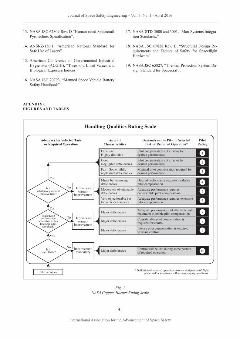
13. NASA JSC 62809 Rev. D “Human-rated Spacecraft Pyrotechnic Specification”.
14. ANSI-Z-136.1, “American National Standard for Safe Use of Lasers”.
15. American Conference of Governmental Industrial Hygienists (ACGIH), “Threshold Limit Values and Biological Exposure Indices”
16. NASA JSC 20793, “Manned Space Vehicle Battery Safety Handbook”
17. NASA-STD-3000 and 3001, “Man-Systems Integra-tion Standards.”
18. NASA JSC 65828 Rev. B, “Structural Design Re-quirements and Factors of Safety for Spaceflight Hardware”.
19. NASA JSC 65827, “Thermal Protection System De-sign Standard for Spacecraft”.
APENDIX C: FIGURES AND TABLES
Fig. 1NASA Copper-Harper Rating Scale
Journal of Space Safety Engineering – Vol. 3 No. 1 - April 2016
41
International Association for the Advancement of Space Safety
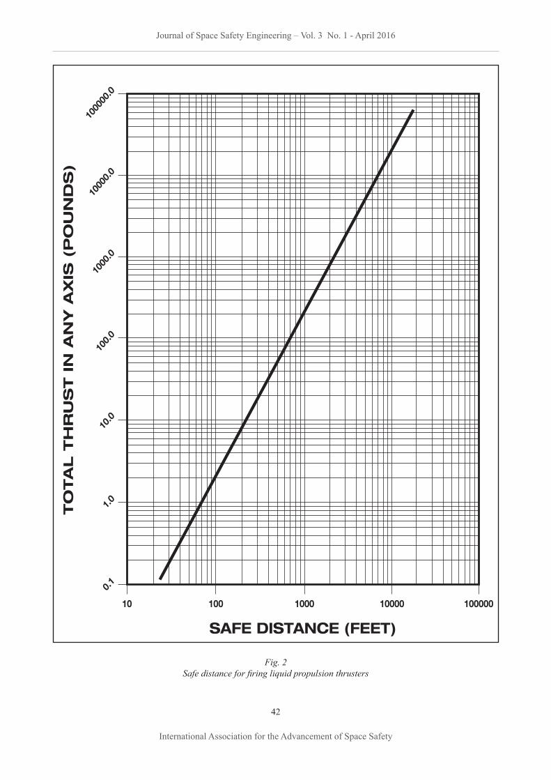
Fig. 2Safe distance for firing liquid propulsion thrusters
Journal of Space Safety Engineering – Vol. 3 No. 1 - April 2016
42
International Association for the Advancement of Space Safety
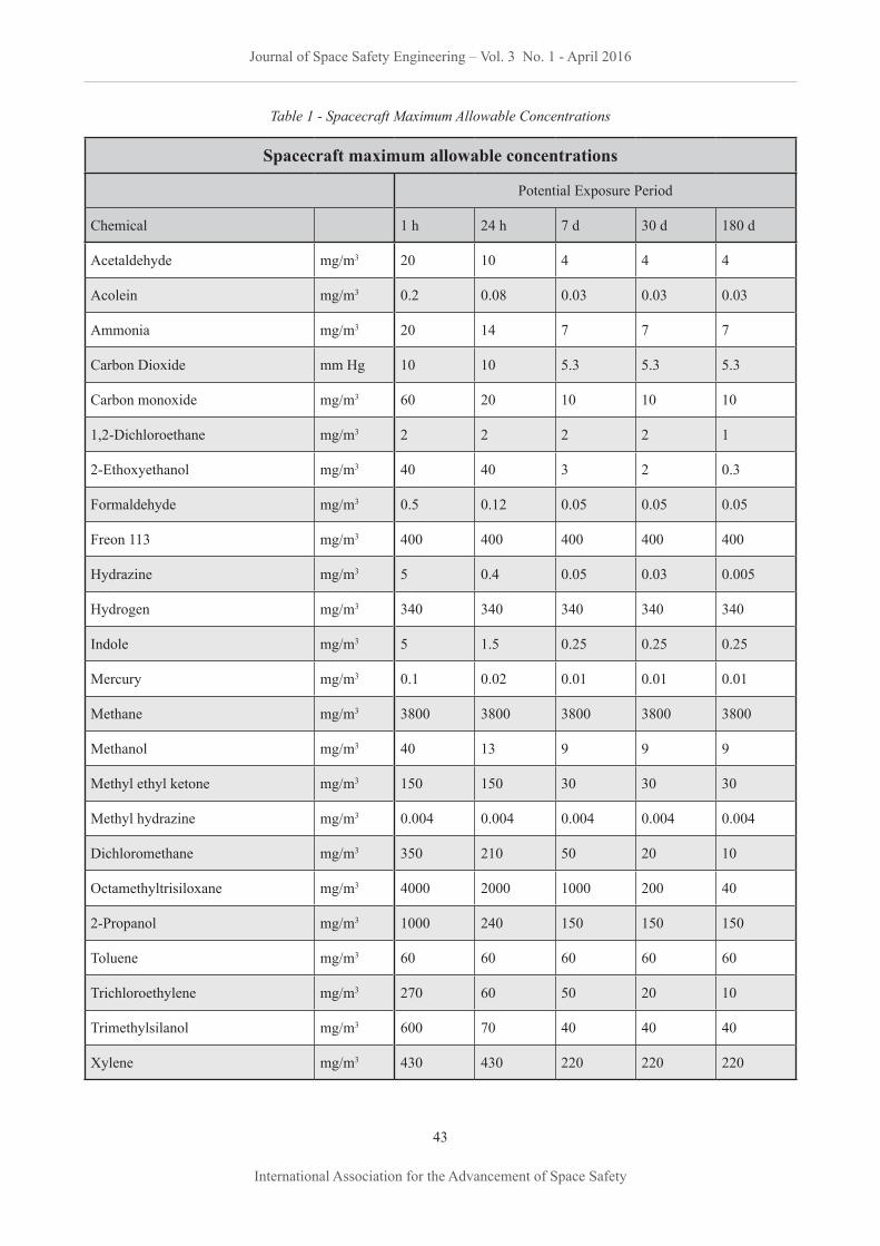
Table 1 - Spacecraft Maximum Allowable Concentrations
Spacecraft maximum allowable concentrations
Potential Exposure Period
Chemical 1 h 24 h 7 d 30 d 180 d
Acetaldehyde mg/m3 20 10 4 4 4
Acolein mg/m3 0.2 0.08 0.03 0.03 0.03
Ammonia mg/m3 20 14 7 7 7
Carbon Dioxide mm Hg 10 10 5.3 5.3 5.3
Carbon monoxide mg/m3 60 20 10 10 10
1,2-Dichloroethane mg/m3 2 2 2 2 1
2-Ethoxyethanol mg/m3 40 40 3 2 0.3
Formaldehyde mg/m3 0.5 0.12 0.05 0.05 0.05
Freon 113 mg/m3 400 400 400 400 400
Hydrazine mg/m3 5 0.4 0.05 0.03 0.005
Hydrogen mg/m3 340 340 340 340 340
Indole mg/m3 5 1.5 0.25 0.25 0.25
Mercury mg/m3 0.1 0.02 0.01 0.01 0.01
Methane mg/m3 3800 3800 3800 3800 3800
Methanol mg/m3 40 13 9 9 9
Methyl ethyl ketone mg/m3 150 150 30 30 30
Methyl hydrazine mg/m3 0.004 0.004 0.004 0.004 0.004
Dichloromethane mg/m3 350 210 50 20 10
Octamethyltrisiloxane mg/m3 4000 2000 1000 200 40
2-Propanol mg/m3 1000 240 150 150 150
Toluene mg/m3 60 60 60 60 60
Trichloroethylene mg/m3 270 60 50 20 10
Trimethylsilanol mg/m3 600 70 40 40 40
Xylene mg/m3 430 430 220 220 220
Journal of Space Safety Engineering – Vol. 3 No. 1 - April 2016
43
International Association for the Advancement of Space Safety
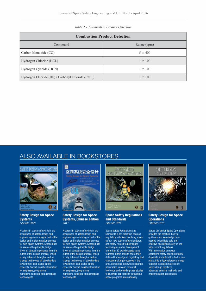
Table 2 - Combustion Product Detection
Combustion Product Detection
Compound Range (ppm)
Carbon Monoxide (CO) 5 to 400
Hydrogen Chloride (HCL) 1 to 100
Hydrogen Cyanide (HCN) 1 to 100
Hydrogen Fluoride (HF) / Carbonyl Fluoride (COF2) 1 to 100
Journal of Space Safety Engineering – Vol. 3 No. 1 - April 2016
44
International Association for the Advancement of Space Safety
Safety Design for Space SystemsElsevier 2009
Progress in space safety lies in the acceptance of safety design and engineering as an integral part of the design and implementation process for new space systems. Safety must be seen as the principle design driver of utmost importance from the outset of the design process, which is only achieved through a culture change that moves all stakeholders toward front-end loaded safety concepts. Superb quality information for engineers, programme managers, suppliers and aerospace technologists.
Safety Design for Space Systems, Chinese Edition2011
Progress in space safety lies in the acceptance of safety design and engineering as an integral part of the design and implementation process for new space systems. Safety must be seen as the principle design driver of utmost importance from the outset of the design process, which is only achieved through a culture change that moves all stakeholders toward front-end loaded safety concepts. Superb quality information for engineers, programme managers, suppliers and aerospace technologists.
Space Safety Regulations and StandardsElsevier 2011
Space Safety Regulations and Standards is the definitive book on regulatory initiatives involving space safety, new space safety standards, and safety related to new space technologies under development. More than 30 world experts come together in this book to share their detailed knowledge of regulatory and standard making processes in the area, combining otherwise disparate information into one essential reference and providing case studies to illustrate applications throughout space programs internationally.
Safety Design for Space OperationsElsevier 2013
Safety Design for Space Operations provides the practical how-to guidance and knowledge base needed to facilitate safe and effective operations safety in line with current regulations. With information on space operations safety design currently disparate and difficult to find in one place, this unique reference brings together essential material on: safety design practices, advanced analysis methods, and implementation procedures.
ALSO AVAILABLE IN BOOKSTORES

SPACE APPLICATIONS FUELING
INNOVATIONBUSINESS
NOVEMBER 15–17, 2016GEORGE R. BROWN CONVENTION CENTER
HOUSTON, TX
Business executives are looking for a competitive advantage. Find yours at SpaceCom. Multiple market segments are exploring
ways to utilize space technologies and
innovations to enhance growth and
profitability. SpaceCom will delve into
these opportunities across its diverse
conference program and interactive
exposition floor. Join us for this exciting
cross-industry convergence.
ENERGY MARITIME
AD
VANCED MANUFACTURIN
G
AGRICULTURE MEDICAL
WWW.SPACECOMEXPO.COM
IN COLLABORATION WITH

INTERNATIONAL ASSOCIATION FOR THE ADVANCEMENT OFSPACE SAFETY
SPACE SAFETY ACADEMY
May 24 - 26, 2016 | Pasadena, CA, USAAmerica’s engineering meeting place for space & defense technology//
Exhibiting companies including Jet Propulsion Laboratory and:
Free-to-attend speaking sessions, including:● Gov/mil/prime requirements day – free-to-
attend presentations from Air Force Space Command, SMC, NASA, JPL, Northrop Grumman, Boeing, Orbital ATK and Lockheed Martin
● GE-hosted technology sessions - featuring speakers from NASA
● Cubesat applications and opportunities
free to attend!
REGISTER FOR A FREE EXPO PASS WWW.SPACETECHEXPO.COM
US SYSTEMS, LLC
don’t miss
Image courtesy of OHB