Embed Size (px)
Citation preview

Michael Hahn – Reporting for TID Vacuum Group and ESRF-II project team
ESRF-II - OVERVIEW
Outline
• ESRF Upgrade Phase I & II
• TDS – Proposal for a new SR
• Constraints
• Vacuum design options
• Chosen strategies
• Pressure simulations
• Implementation, Logistics
• Timeline
• Discussion
Page 2 OLAV IV April 2014 l M. Hahn
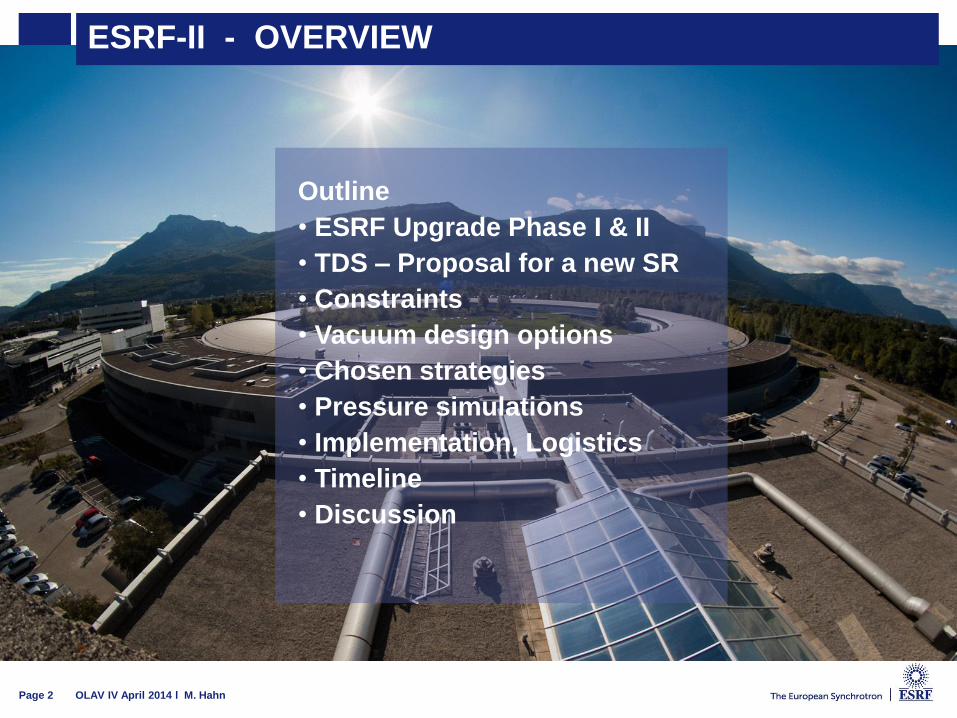
MOTIVATION: ESRF – UPGRADE
Page 3 OLAV IV April 2014 l M. Hahn
• Phase I & II of the
ESRF upgrade
• Phase 1 (2009 – 2015)
- new Experimental halls
and lab / office buildings
- Some source
improvements (6m
straight sections, HOM
damped cavities, Solid
state amplifiers…)
- Beamline upgrades and
refurbishments – many
long beamlines
- Close to completion
• Phase 2 (2016-2021)
Substantial source
upgrade
- Replace the lattice of
the electron storage ring -
- Proposal, Technical
design study report (TDS)
close to completion
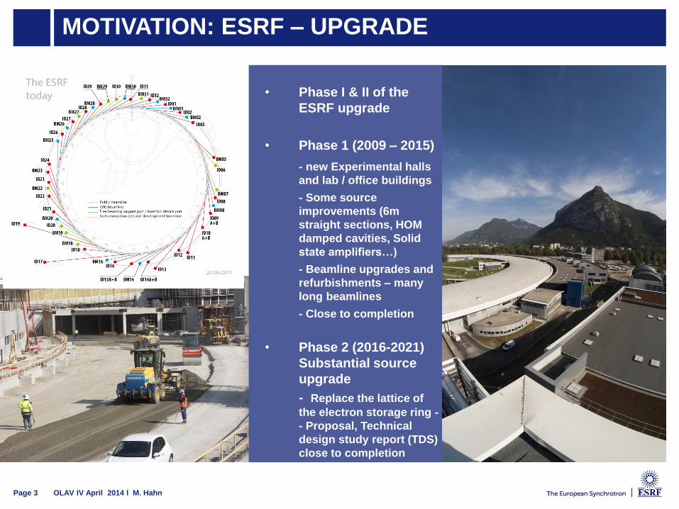
ESRF – UPGRADE PHASE I - BEAMLINES
Page 4 OLAV IV April 2014 l M. Hahn
UPBL01 / ID01
UPBL02 / ID31
UPBL04 / ID16A
UPBL04 / ID16B
UPBL06 / ID20
UPBL07 / ID32
UPBL09A / ID02
UPBL09B / ID09TR
UPBL10 / ID30
UPBL11 / ID24
ID10 Refurbishment
ID15 Refurbishment
ID19 Refurbishment
ID31 -> ID22 Transfer

ESRF – UPGRADE PHASE I – MACHINE SIDE
Page 5 OLAV IV April 2014 l M. Hahn
Phase I & II of the ESRF upgrade
• Phase 1 (2009 – 2015)
• 8 x extension of straight sections from
5m to 6m
• 1 x extension from 5m to 7m to receive
three HOM-damped cavities and
canted insertion devices
• Solid-State amplifiers to replace
Klystrons driving cavities on the
booster synchrotron and storage ring
• New In-Vacuum undulators optimized
for longer straights, cryo-cooled
(100K) and RT
• Test of the injector to allow for
Topping-up
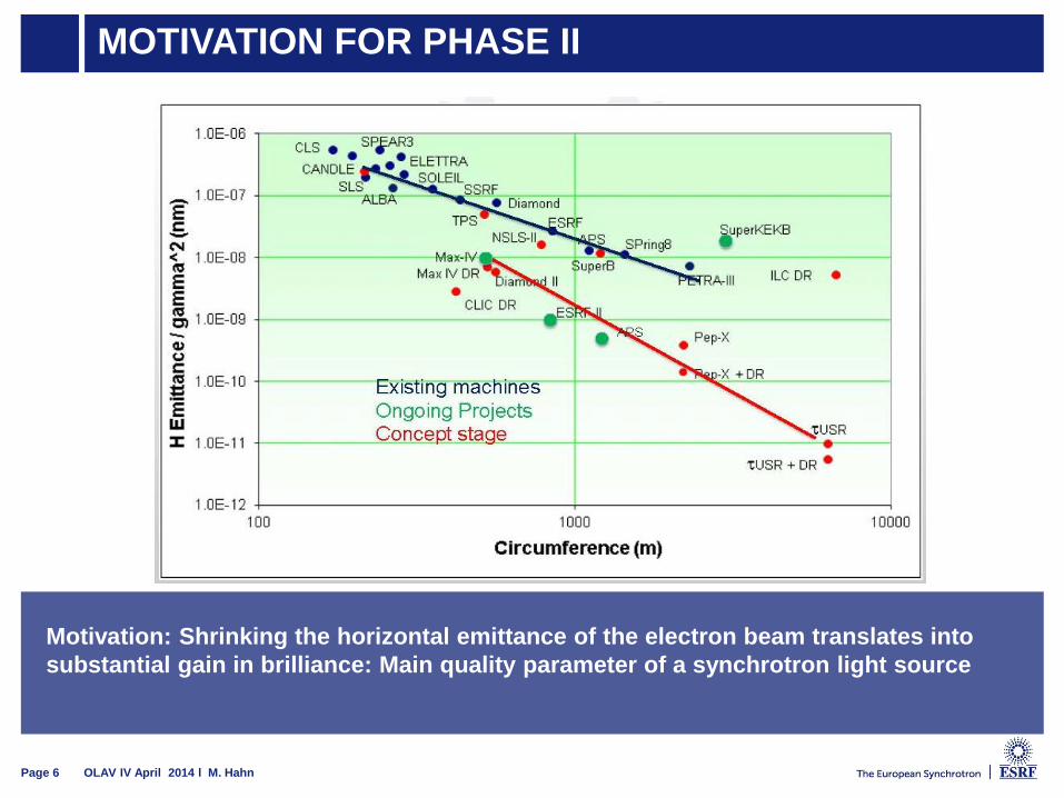
MOTIVATION FOR PHASE II
Motivation: Shrinking the horizontal emittance of the electron beam translates into
substantial gain in brilliance: Main quality parameter of a synchrotron light source
Page 6 OLAV IV April 2014 l M. Hahn

MOTIVATION
Page 7 OLAV IV April 2014 l M. Hahn
ESRF New lattice
Lattice type DBA HMB
Circumference [m] 844.390 843.979
Beam Energy [GeV] 6.04 6
Beam Current [mA] 200 200
Natural emittance [pm] 4000 147
Energy spread [%] 0.106 0.095
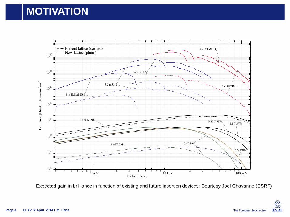
MOTIVATION
Page 8 OLAV IV April 2014 l M. Hahn
Expected gain in brilliance in function of existing and future insertion devices: Courtesy Joel Chavanne (ESRF)
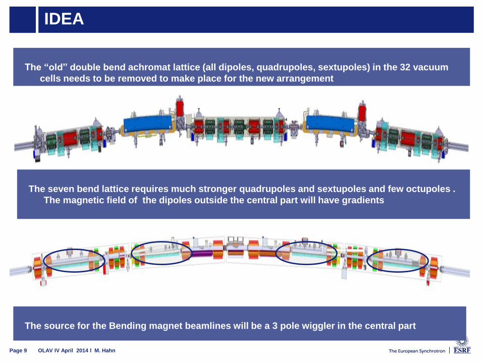
IDEA
Page 9 OLAV IV April 2014 l M. Hahn
The “old” double bend achromat lattice (all dipoles, quadrupoles, sextupoles) in the 32 vacuum
cells needs to be removed to make place for the new arrangement
The seven bend lattice requires much stronger quadrupoles and sextupoles and few octupoles .
The magnetic field of the dipoles outside the central part will have gradients
The source for the Bending magnet beamlines will be a 3 pole wiggler in the central part
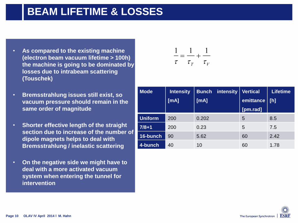
BEAM LIFETIME & LOSSES
Page 10 OLAV IV April 2014 l M. Hahn
1
1
T1
V
Mode Intensity
[mA]
Bunch intensity
[mA]
Vertical
emittance
[pm.rad]
Lifetime
[h]
Uniform 200 0.202 5 8.5
7/8+1 200 0.23 5 7.5
16-bunch 90 5.62 60 2.42
4-bunch 40 10 60 1.78
• As compared to the existing machine
(electron beam vacuum lifetime > 100h)
the machine is going to be dominated by
losses due to intrabeam scattering
(Touschek)
• Bremsstrahlung issues still exist, so
vacuum pressure should remain in the
same order of magnitude
• Shorter effective length of the straight
section due to increase of the number of
dipole magnets helps to deal with
Bremsstrahlung / inelastic scattering
• On the negative side we might have to
deal with a more activated vacuum
system when entering the tunnel for
intervention
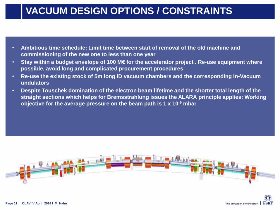
VACUUM DESIGN OPTIONS / CONSTRAINTS
Page 11 OLAV IV April 2014 l M. Hahn
• Ambitious time schedule: Limit time between start of removal of the old machine and
commissioning of the new one to less than one year
• Stay within a budget envelope of 100 M€ for the accelerator project . Re-use equipment where
possible, avoid long and complicated procurement procedures
• Re-use the existing stock of 5m long ID vacuum chambers and the corresponding In-Vacuum
undulators
• Despite Touschek domination of the electron beam lifetime and the shorter total length of the
straight sections which helps for Bremsstrahlung issues the ALARA principle applies: Working
objective for the average pressure on the beam path is 1 x 10⁻⁹ mbar
• On the negative side we will have to deal with a more activated vacuum system when entering the
tunnel for intervention
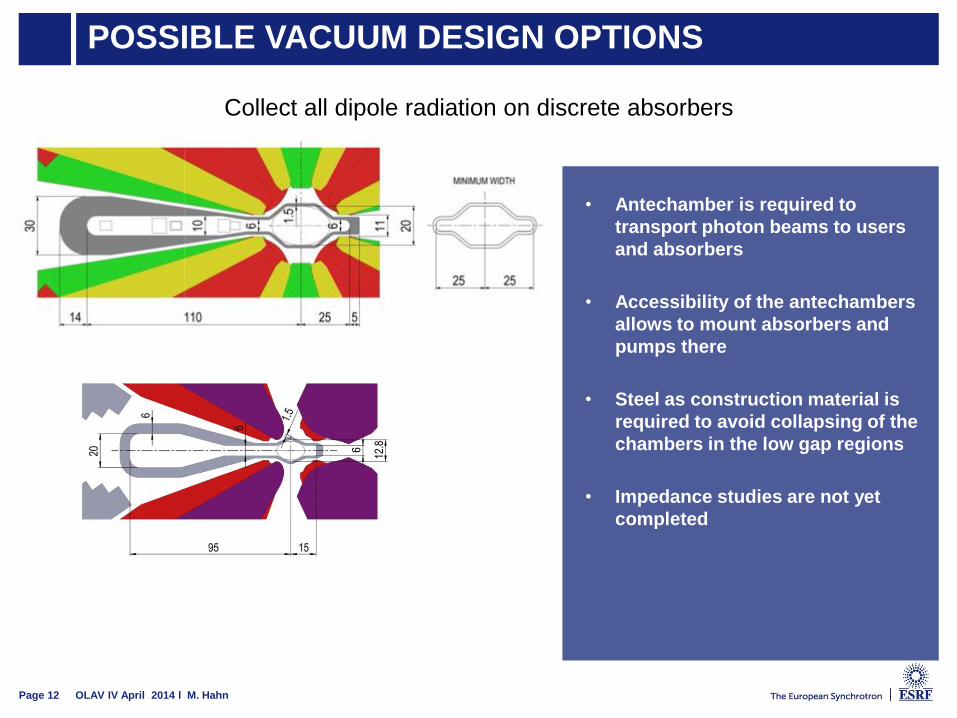
POSSIBLE VACUUM DESIGN OPTIONS
Page 12 OLAV IV April 2014 l M. Hahn
Collect all dipole radiation on discrete absorbers
• Antechamber is required to
transport photon beams to users
and absorbers
• Accessibility of the antechambers
allows to mount absorbers and
pumps there
• Steel as construction material is
required to avoid collapsing of the
chambers in the low gap regions
• Impedance studies are not yet
completed

POSSIBLE VACUUM DESIGN OPTIONS
Page 13 OLAV IV April 2014 l M. Hahn
Intense use of NEG coatings: Fully coated machine for either rely only on distributed absorbers
(Max-IV) or combination of lumped absorbers and distributed absorbers up to about 150 W/m
• Idea: Apply NEG Coating
to all vacuum chambers of
the “standard cell”
(dipoles, quadrupoles,
sextupoles, octupoles)
• Profit from the upgraded
ESRF coating facility
(double surface) which
provides three coating
benches
• It was estimated that 50%
of the required 700m of
coated chambers (plus
spare) could have been
coated in-houseHorizontal Vertical
Cell centre ±8 mm ±5.5 mm
Cell ends ±15 mm ±10 mm
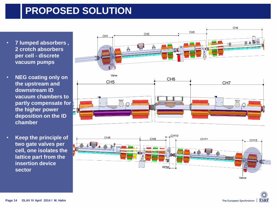
PROPOSED SOLUTION
Page 14 OLAV IV April 2014 l M. Hahn
• 7 lumped absorbers ,
2 crotch absorbers
per cell - discrete
vacuum pumps
• NEG coating only on
the upstream and
downstream ID
vacuum chambers to
partly compensate for
the higher power
deposition on the ID
chamber
• Keep the principle of
two gate valves per
cell, one isolates the
lattice part from the
insertion device
sector
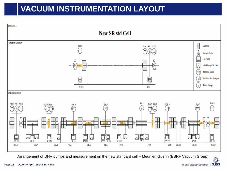
VACUUM INSTRUMENTATION LAYOUT
Page 15 OLAV IV April 2014 l M. Hahn
Arrangement of UHV pumps and measurement on the new standard cell – Meunier, Guerin (ESRF Vacuum Group)
VACUUM EQUIPMENT KEYWORDS
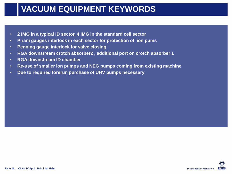
Page 16 OLAV IV April 2014 l M. Hahn
• 2 IMG in a typical ID sector, 4 IMG in the standard cell sector
• Pirani gauges interlock in each sector for protection of ion pums
• Penning gauge interlock for valve closing
• RGA downstream crotch absorber2 , additional port on crotch absorber 1
• RGA downstream ID chamber
• Re-use of smaller ion pumps and NEG pumps coming from existing machine
• Due to required forerun purchase of UHV pumps necessary
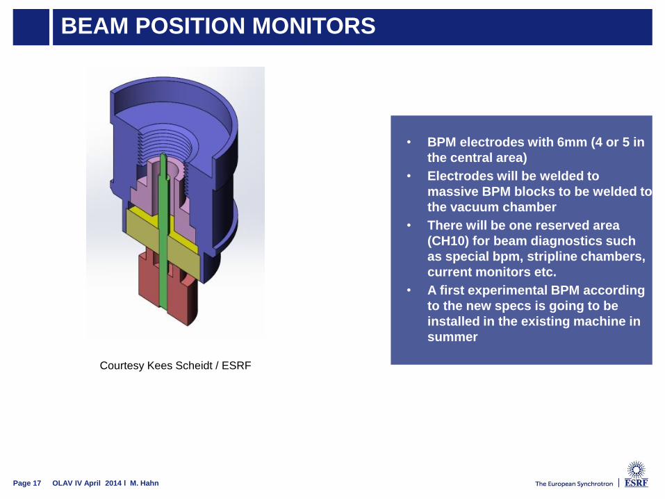
BEAM POSITION MONITORS
Page 17 OLAV IV April 2014 l M. Hahn
Courtesy Kees Scheidt / ESRF
• BPM electrodes with 6mm (4 or 5 in
the central area)
• Electrodes will be welded to
massive BPM blocks to be welded to
the vacuum chamber
• There will be one reserved area
(CH10) for beam diagnostics such
as special bpm, stripline chambers,
current monitors etc.
• A first experimental BPM according
to the new specs is going to be
installed in the existing machine in
summer
PRESSURE SIMULATION
Page 18 OLAV IV April 2014 l M. Hahn
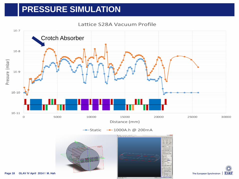
Crotch Absorber
PRESSURE SIMULATION
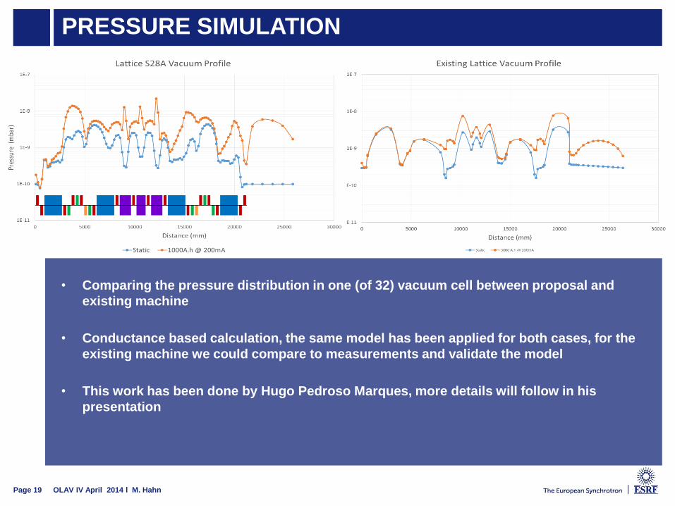
Page 19 OLAV IV April 2014 l M. Hahn
• Comparing the pressure distribution in one (of 32) vacuum cell between proposal and
existing machine
• Conductance based calculation, the same model has been applied for both cases, for the
existing machine we could compare to measurements and validate the model
• This work has been done by Hugo Pedroso Marques, more details will follow in his
presentation
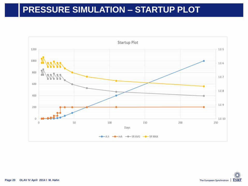
PRESSURE SIMULATION – STARTUP PLOT
Page 20 OLAV IV April 2014 l M. Hahn

LOGISTICS
Page 21 OLAV IV April 2014 l M. Hahn
• The disassembly of the existing machine will be difficult due to the time
constraints to get the new compenents in on one hand and the fact that all
equipment needs to be measured and qualified in terms of activation by the
Safety Group on the other
• Pre-assemble magnets, vacuum chamber and baking equipment on the girder
and bring the complete assembly to the tunnel
• ESRF overhead craned cannot take the mass of at least girder 3 (maximum load
6.3t) so it is envisaged to bring the assemblies through two dedicated tunnel
openings and slide them to position
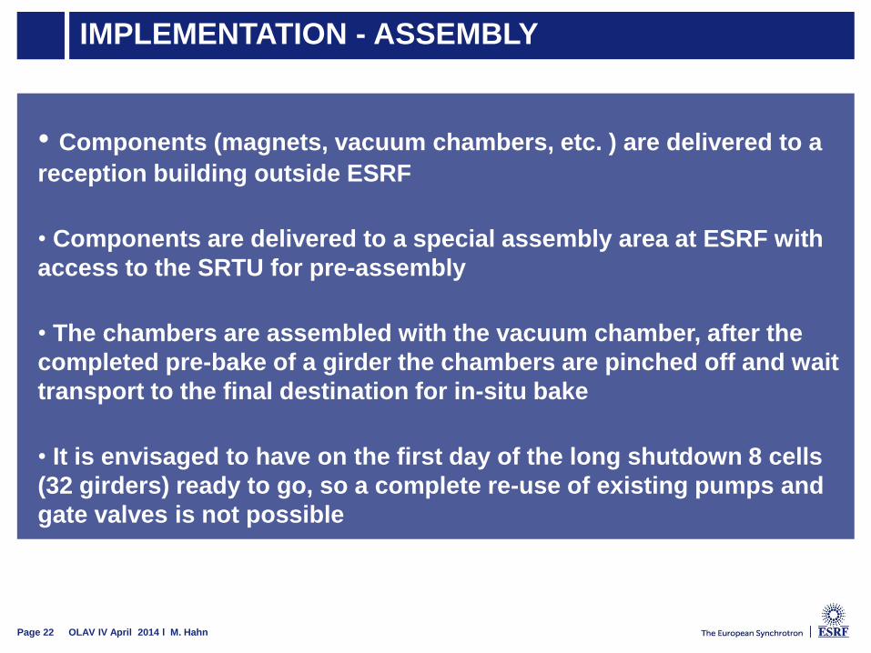
IMPLEMENTATION - ASSEMBLY
Page 22 OLAV IV April 2014 l M. Hahn
• Components (magnets, vacuum chambers, etc. ) are delivered to a
reception building outside ESRF
• Components are delivered to a special assembly area at ESRF with
access to the SRTU for pre-assembly
• The chambers are assembled with the vacuum chamber, after the
completed pre-bake of a girder the chambers are pinched off and wait
transport to the final destination for in-situ bake
• It is envisaged to have on the first day of the long shutdown 8 cells
(32 girders) ready to go, so a complete re-use of existing pumps and
gate valves is not possible
IMPLEMENTATION – INSTALLATION & BAKE
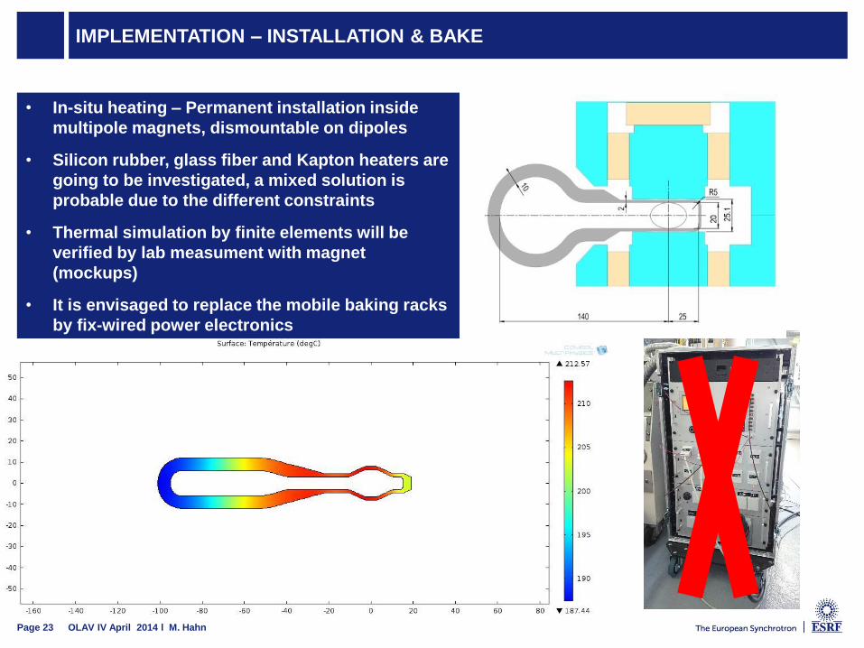
OLAV IV April 2014 l M. HahnPage 23
• In-situ heating – Permanent installation inside
multipole magnets, dismountable on dipoles
• Silicon rubber, glass fiber and Kapton heaters are
going to be investigated, a mixed solution is
probable due to the different constraints
• Thermal simulation by finite elements will be
verified by lab measument with magnet
(mockups)
• It is envisaged to replace the mobile baking racks
by fix-wired power electronics
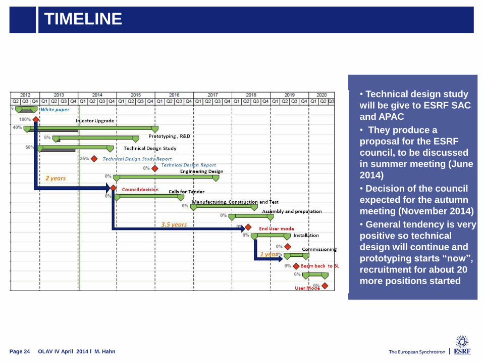
TIMELINE
• Technical design study
will be give to ESRF SAC
and APAC
• They produce a
proposal for the ESRF
council, to be discussed
in summer meeting (June
2014)
• Decision of the council
expected for the autumn
meeting (November 2014)
• General tendency is very
positive so technical
design will continue and
prototyping starts “now”,
recruitment for about 20
more positions started
Page 24 OLAV IV April 2014 l M. Hahn
DISCUSSION
Thank you for your attention
Page 25 OLAC IV April 2014 l M. Hahn