Embed Size (px)
Citation preview

Michael Gentile, Site Acquisition
c/o New Cingular Wireless, PCS LLC (AT&T)
Centerline Communications, LLC
95 Ryan Drive, Suite 1
Raynham, MA 02767
Mobile: (508) 844-9813
February 18, 2016
Melanie A. Bachman
Acting Executive Director
Connecticut Siting Council
10 Franklin Square
New Britain, CT 06051
RE: Notice of Exempt Modification // Site Number: CT2102
5 Perryridge Road, Greenwich, CT (Site Name: Greenwich Perryridge Road Tower)
N 41.0339361 // W -73.63080333
Dear Ms. Bachman:
New Cingular Wireless, PCS, LLC (“AT&T”) currently maintains nine (9) antennas at the 134
foot level of the existing 164 foot monopole tower at 5 Perryridge Road, Greenwich, CT 06830.
The tower is owned by Greenwich Hospital. The property is also owned by Greenwich Hospital.
AT&T now intends to replace three (3) of its existing antennas with three (3) new LTE
(700/1900 band) antennas for its LTE upgrade. These antennas would be installed at the same
134 foot level of the tower. AT&T also intends to remove three (3) remote radio units and install
six (6) remote radio units and three (3) remote radio unit modules, six (6) triplexers, one (1)
surge arrestor, two (2) DC power lines and one (1) fiber line. All equipment will be mounted at
the 134 foot level except for the proposed surge arrestor, which will be mounted at the 138 foot
level.
The current proposal involves an antenna swap only (three for three); no antennas will be added.
AT&T was originally approved for six (6) antennas on 9/25/2008 and subsequently approved for
three (3) additional antennas and various ancillary equipment on 5/31/2011.
Please accept this letter as notification pursuant to Regulations of Connecticut State Agencies §
16-50j-73, for construction that constitutes an exempt modification pursuant to R.C.S.A. § 16-
50j-72(b)(2). In accordance with R.C.S.A. § 16-50j-73, a copy of this letter is being sent to Peter
Tesei, First Selectman for the Town of Greenwich, as well as the tower owner, Greenwich
Hospital and the ground owner, who is also Greenwich Hospital.
The planned modifications to the facility fall squarely within those activities explicitly provided
for in R.C.S.A. § 16-50j-72(b)(2).

Attached to accommodate this filing are construction drawings dated 2/10/2016 by ComEx
Consultants, a structural analysis dated 1/21/2016 by Centek Engineering and an Emissions
Analysis Report dated 2/9/2016 by EBI Consulting
1. The proposed modifications will not result in an increase in the height of the existing structure.
2. The proposed modifications will not require the extension of the site boundary.
3. The proposed modifications will not increase noise levels at the facility by six decibels or
more, or to levels that exceed state and local criteria.
4. The operation of the replacement antennas will not increase radio frequency emissions at the
facility to a level at or above the Federal Communications Commission safety standard.
5. The proposed modifications will not cause a change or alteration in the physical or
environmental characteristics of the site.
6. The existing structure and its foundation can support the proposed loading as shown in the
attached structural analysis by Centek Engineering dated 1/21/2016.
For the foregoing reasons, AT&T respectfully submits that the proposed modifications to the
above referenced telecommunications facility constitute an exempt modification under R.C.S.A.
§ 16-50j-72(b)(2).
Sincerely,
_____________________________________
Michael Gentile, Site Acquisition
c/o New Cingular Wireless, PCS LLC (AT&T)
Centerline Communications, LLC
95 Ryan Drive, Suite 1
Raynham, MA 02767
Mobile: (508) 844-9813
Attachments
cc: Peter Tesei, First Selectman, Town of Greenwich - as elected official
Greenwich Hospital - as tower owner
Greenwich Hospital - as property owner

S t r u c t u r a l A n a l y s i s R e p o r t
1 6 4 - f t E x i s t i n g E E I M o n o p o l e
P r o p o s e d A T & T M o b i l i t yA n t e n n a U p g r a d e
A T & T S i t e R e f : C T 2 1 0 2
5 P e r r y r i d g e R o a dG r e e n w i c h , C T
C E N T E K P r o j e c t N o . 1 6 0 0 2 . 0 0 5
D a t e : J a n u a r y 2 1 , 2 0 1 6
Prepared for:AT&T Mobil ity
500 Enterprise Dr ive, Suite 3ARocky Hil l , CT 06067

CENTEK Engineering, Inc.Structural Analysis – 164-ft EEI MonopoleAT&T Mobility Antenna Upgrade – CT2102Greenwich, CTJanuary 21, 2016
TABLE OF CONTENTS TOC-1
T a b l e o f C o n t e n t sSECTION 1 - REPORT
§ INTRODUCTION
§ ANTENNA AND APPURTENANCE SUMMARY
§ PRIMARY ASSUMPTIONS USED IN THE ANALYSIS
§ ANALYSIS
§ TOWER LOADING
§ TOWER CAPACITY
§ FOUNDATION AND ANCHORS
§ CONCLUSION
SECTION 2 – CONDITIONS & SOFTWARE
§ STANDARD ENGINEERING CONDITIONS
§ GENERAL DESCRIPTION OF STRUCTURAL ANALYSIS PROGRAM
SECTION 3 – CALCULATIONS
§ tnxTower INPUT/OUTPUT SUMMARY
§ tnxTower DETAILED OUTPUT
§ FLANGE BOLT AND FLANGE PLATE ANALYSIS
§ ANCHOR BOLT AND BASE PLATE ANALYSIS
§ MathCAD CAISSON FOUNDATION ANALYSIS
§ L-PILE CAISSON ANALYSIS
§ L-PILE LATERAL DEFLECTION vs. DEPTH
§ L-PILE BENDING MOMENT vs. DEPTH
§ L-PILE SHEAR FORCE vs. DEPTH
SECTION 4 – REFERENCE MATERIAL
§ RF DATA SHEET
§ ANTENNA DATA SHEETS

CENTEK Engineering, Inc.Structural Analysis – 164-ft EEI MonopoleAT&T Mobility Antenna Upgrade – CT2102Greenwich, CTJanuary 21, 2016
REPORT SECTION 1-1
I n t r o d u c t i o n
The purpose of this report is to summarize the results of the non-linear, P-∆ structural analysisof the antenna upgrade proposed by AT&T Mobility on the existing monopole (tower) ownedand operated by Greenwich Hospital located in Greenwich, Connecticut.
The host tower is a 164-ft tall, five-section, eighteen sided, tapered monopole, originallydesigned and manufactured by Engineered Endeavors Incorporated (EEI); project no. 11030dated August 21, 2002. The tower geometry, structure member sizes and foundation systeminformation were obtained from the original manufacturers design documents.
Antenna and appurtenance information were obtained a previous structural analysis reportprepared by Centek; job no; 15001.145, dated January 20, 2016 and a AT&T RF data sheet.
The tower is made up of five (5) tapered vertical sections consisting of A572-65 pole sections.The bottom four (4) vertical tower sections are slip joint connected while the top section is flangeconnected. The diameter of the pole (flat-flat) is 47.0-in at the top and 76.0-in at the base.
AT&T proposes the removal of three (3) panel antennas and three (3) remote radio heads andthe installation of three (3) panel antennas, six (6) remote radio heads and one (1) surgearrestor mounted to the existing low profile platform. Refer to the Antenna and AppurtenanceSummary below for a detailed description of the proposed antenna and appurtenanceconfiguration.
A n t e n n a a n d A p p u r t e n a n c e S u m m a r yThe existing, proposed and future loads considered in this analysis consist of the following:
§ TOWN (EXISTING):Antennas: One (1) 12-ft Omni-directional whip antenna, two (2) 10-ft Omni-directional whip antennas, two (2) 8-ft Omni-directional whip antennas, one KathreinScala 2’ square panel and one (1) camera mounted on a PiROD 13-ft low profileplatform with an elevation of 164-ft above grade level.Coax Cables: Six (6) 1/2” Æ, one (1) 5/8” Æ, three (3) 7/8” Æ and two (2) 1-1/4” Æcoax cables running on the inside of the existing tower.
§ TOWN (EXISTING):Antennas: Two (2) 4 FT Dishes and one (1) 2 Ft Dish mounted on three 4’x4” pipemounts with a RAD center elevation of 160-ft above grade level.Coax Cables: Three (3) 1-1/4” Æ coax cables running on the inside of the existingtower.
§ CLEARWIRE (EXISTING):Antennas: Three (3) Argus LLPX310R panel antennas, three (3) Samsung FDD-R6-RRH, two (2) Dragonwave Horizon ODU’s and two (2) Dragonwave A-ANT-23-G-2-Cdishes mounted on the Sprint 13-ft low profile platform with a RAD center elevationof 154-ft above the existing tower base plate.Coax Cables: Two (2) 2” Æ conduits and two (2) 5/8” Æ coax cables running on theinside of the existing tower.

CENTEK Engineering, Inc.Structural Analysis – 164-ft EEI MonopoleAT&T Mobility Antenna Upgrade – CT2102Greenwich, CTJanuary 21, 2016
REPORT SECTION 1-2
§ SPRINT (EXISTING):Antennas: Two (2) RFS APXVSPP18-C-A20 panel antennas, one (1) PowerwaveP40-16-XLPP-RR-A panel antennas, three (3) RFS APXVTM14 panel antennas andone (1) GPS antenna mounted to a low profile platform with a RAD center elevationof 154-ft above the existing tower base plate. Three (3) ALU 1900 MHz RRH’s, three(3) ALU 800 MHz RRH’s and three (3) ALU TD-RRH-820 remote radio headsmounted on a universal tr-bracket below the existing low profile platform.Coax Cables: Six (6) 1-5/8” Æ Hybriflex cables and one (1) 1/2” Æ coax cablerunning on the inside of the existing tower.
§ T-MOBILE (EXISTING):Antennas: Three (3) RFS APX16PV-16PVL panel antennas, three (3) Andrew LNX-6515DS panel antennas, nine (9) TMA’s and three (3) Bias Tee’s mounted on aPiROD 13-ft low profile platform with a RAD center elevation of 144-ft above gradelevel.Coax Cables: Twelve (12) 1-5/8” Æ coax cables inside the monopole and six (6) 1-5/8” Æ cables on the exterior of the existing tower.
§ EVERSOURCE ENERGY (EXISTING):Antennas: Two (2) Decibel DB586-Y omni-directional whips (one upright and oneinverted), one (1) Telewave ANT150F2 omni-directional whip, one (1) Comprod 531-70HD dipole and one (1) tower top amplifier mounted on a PiROD 13-ft low profileplatform with an elevation of 114-ft above grade level.Coax Cables: Two (2) 1-5/8” Æ, two (2) 7/8” Æ and one (1) 1/2” Æ coax cablesrunning on the inside of the existing toweron the inside of the existing tower.
§ UNKNOWN (EXISTING):Antennas: Three GPS antennas mounted on three (3) standoffs with a RAD centerelevation of 50-ft above grade level.Coax Cables: Three (3) 7/8” Æ coax cables running on the exterior of the existingtower.
§ VERIZON (EXISTING):Antennas: Six (6) Decibel DB844H65E-XY panel antennas, three (3) RYMSA MGD3-800T0 panel antennas, six (6) Andrew SBNHH-1D65B panel antennas, three (3)Alcatel-Lucent RRH2x60-700 remote radio heads, three (3) Alcatel-LucentRRH2x60-PCS remote radio heads, three (3) Alcatel-Lucent RRH4x45/2x90-AWSremote radio heads, six (6) RFS FD9R6004/2C-3L Diplexers and two (2) RaycapRC2DC-3315-PF-48 main distribution boxes mounted on a 13-ft low profile platformwith a RAD center elevation of 124-ft above grade level.Coax Cables: Six (6) 1-5/8” Æ coax cables and two (2) 1-5/8” Æ fiber cables runninginside the monopole.

CENTEK Engineering, Inc.Structural Analysis – 164-ft EEI MonopoleAT&T Mobility Antenna Upgrade – CT2102Greenwich, CTJanuary 21, 2016
REPORT SECTION 1-3
§ AT&T (EXISTING TO REMAIN):Antennas: Three (3) Powerwave 7770.00 panel antennas, three (3) PowerwaveP65-16-XLH-RR panel antennas, six (6) LGP21401 TMA’s and six (6) LGP21901diplexers mounted on a PiROD 13-ft low profile platform with a RAD center elevationof 134-ft above grade level. Three (3) Ericsson RRUS-11 remote radio heads andone (1) Raycap DC6-48-60-18-8F surge arrestor mounted to one (1) universal ringmount with a RAD center elevation of 138-ft above grade level.Cables: Twelve (12) 1-5/8” Æ coax cables, one (1) fiber cable and two (2) dc controlcables running on the inside of the existing tower
§ AT&T (EXISTING TO REMOVE):Antennas: Three (3) Powerwave 7770.00 panel antennas 13-ft low profile platformwith a RAD center elevation of 134-ft above grade level. Three (3) Ericsson RRUS-11 remote radio heads mounted to one (1) universal ring mount with a RAD centerelevation of 138-ft above grade level.
§ AT&T (PROPOSED):Antennas: Three (3) Quintel QS66512-3 panel antennas, six (6) CCI TPX-070821 triplexers, three (3) Ericsson RRUS-12 remote radio heads, three (3)Ericsson RRUS-32 remote radio heads and three (3) Ericsson A2 unitsmounted on a PiROD 13-ft low profile platform with a RAD center elevation of134-ft above grade level. One (1) Raycap DC6-48-60-18-8F surge arrestormounted to one (1) universal ring mount with a RAD center elevation of 138-ftabove grade level.Cables: One (1) fiber cable and two (2) dc control cables running on the inside ofthe existing tower.

CENTEK Engineering, Inc.Structural Analysis – 164-ft EEI MonopoleAT&T Mobility Antenna Upgrade – CT2102Greenwich, CTJanuary 21, 2016
REPORT SECTION 1-4
P r i m a r y A s s u m p t i o n s U s e d i n t h e A n a l y s i s§ The tower structure’s theoretical capacity not including any assessment of the
condition of the tower.
§ The tower carries the horizontal and vertical loads due to the weight of antennas, iceload and wind.
§ Tower is properly installed and maintained.
§ Tower is in plumb condition.
§ Tower loading for antennas and mounts as listed in this report.
§ All bolts are appropriately tightened providing the necessary connection continuity.
§ All welds are fabricated with ER-70S-6 electrodes.
§ All members are assumed to be as specified in the original tower design documentsor reinforcement drawings.
§ All members are “hot dipped” galvanized in accordance with ASTM A123 and ASTMA153 Standards.
§ All member protective coatings are in good condition.
§ All tower members were properly designed, detailed, fabricated, installed and havebeen properly maintained since erection.
§ Any deviation from the analyzed antenna loading will require a new analysis forverification of structural adequacy.
§ All coax cables to be installed as indicated in this report.

CENTEK Engineering, Inc.Structural Analysis – 164-ft EEI MonopoleAT&T Mobility Antenna Upgrade – CT2102Greenwich, CTJanuary 21, 2016
REPORT SECTION 1-5
A n a l y s i sThe existing tower was analyzed using a comprehensive computer program entitled tnxTower.The program analyzes the tower, considering the worst case loading condition. The tower isconsidered as loaded by concentric forces along the tower shaft, and the model assumes thatthe shaft members are subjected to bending, axial, and shear forces.
The existing tower was analyzed for the controlling basic wind speed (fastest mile) with no iceand a 75% reduction of wind force with ½ inch accumulative ice to determine stresses inmembers as per guidelines of TIA/EIA-222-F-96 entitled “Structural Standards for Steel AntennaTowers and Antenna Supporting Structures”, the American Institute of Steel Construction(AISC) and the Manual of Steel Construction; Allowable Stress Design (ASD).
The controlling wind speed is determined by evaluating the local available wind speed data asprovided in Appendix K of the CSBC1 and the wind speed data available in the TIA/EIA-222-F-96 Standard. The higher of the two wind speeds is utilized in preparation on the tower analysis.
T o w e r L o a d i n g
Tower loading was determined by the basic wind speed as applied to projected surface areaswith modification factors per TIA/EIA-222-F, gravity loads of the tower structure and itscomponents, and the application of ½” radial ice on the tower structure and its components.
Basic WindSpeed:
Fairfield; v = 85 mph (fastest mile)
Greenwich; v = 100 mph (3 secondgust) equivalent to v = 80 mph(fastest mile)
TIA/EIA wind speed controls.
[Section 16 of TIA/EIA-222-F-96]
[Appendix K of the 2005 CTBuilding Code Supplement]
Load Cases: Load Case 1; 85 mph wind speed w/no ice plus gravity load – used incalculation of tower stresses androtation.
[Section 2.3.16 of TIA/EIA-222-F-96]
Load Case 2; 74 mph wind speed w/½” radial ice plus gravity load – usedin calculation of tower stresses. The74 mph wind speed velocityrepresents 75% of the wind pressuregenerated by the 85 mph windspeed.
[Section 2.3.16 of TIA/EIA-222-F-96]
Load Case 3; Seismic – not checked [Section 1614.5 of State Bldg.Code 2005] does not control inthe design of this structure type
1 The 2005 Connecticut State Building Code as amended by the 2009 CT State Supplement. (CSBC)

CENTEK Engineering, Inc.Structural Analysis – 164-ft EEI MonopoleAT&T Mobility Antenna Upgrade – CT2102Greenwich, CTJanuary 21, 2016
REPORT SECTION 1-6
T o w e r C a p a c i t y
Tower stresses were calculated utilizing the structural analysis software tnxTower. Allowablestresses were determined based on Table 5 of the TIA/EIA code with a 1/3 increase per Section3.1.1.1 of the same code.
§ Calculated stresses were found to be within allowable limits. In Load Case 1, per tnxTower“Section Capacity Table”, this tower was found to be at 50.0% of its total capacity.
Tower Section ElevationStress Ratio
(percentage ofcapacity)
Result
Pole Shaft (L5) 1.50’-39.88’ 50.0% PASS
§ The tower deflection (tilt) was found to be within allowable limits.
(1) Allowable tilt taken from original EEI design documents job no. 11030 dated 8/21/02.
F o u n d a t i o n a n d A n c h o r sThe existing foundation consists of a 9.0 Æ x 28.0-ft long reinforced concrete caisson. The sub-grade conditions used in the analysis of the existing foundation were obtained from theaforementioned EEI design report; project no. 11030 dated August 21, 2002. The base of thetower is connected to the foundation by means of (30) 2.25”Æ, ASTM A615-75 anchor boltsembedded approximately 7-ft into the concrete foundation structure.
§ The tower base reactions developed from the governing Load Case 1 were used in theverification of the foundation and its anchors:
Location Vector Proposed Reactions
BaseShear 46 kips
Compression 83 kipsMoment 5220 kip-ft
§ The foundation was found to be within allowable limits.
(1) Lateral deflection typically limited to 1.0 in. for monopole tower structures.
Deflection (degrees) Proposed Allowable (1) Result
Tilt 1.47 1.9 PASS
Foundation Design Limit ProposedLoading
Result
Reinforced ConcreteCaisson
Moment Capacity 65.0% PASSLateral Deflection 0.61 in.(1) PASS

CENTEK Engineering, Inc.Structural Analysis – 164-ft EEI MonopoleAT&T Mobility Antenna Upgrade – CT2102Greenwich, CTJanuary 21, 2016
REPORT SECTION 1-7
§ The flange bolts and plate were found to be within allowable limits.
TowerComponent Design Limit
Stress Ratio(percentage of
capacity)Result
Flange Bolts Tension 55.9% PASS
Flange Plate Bending 43.5% PASS
§ The anchor bolts and base plate were found to be within allowable limits.
TowerComponent Design Limit
Stress Ratio(percentage of
capacity)Result
Anchor Bolts Combined Axialand Bending 51.3% PASS
Base Plate Bending 40.2% PASS
C o n c l u s i o nThis analysis shows that the subject tower is adequate to support the proposed modifiedantenna configuration.
The analysis is based, in part, on the information provided to this office by AT&T Mobilty. If theexisting conditions are different than the information in this report, Centek Engineering, Inc.must be contacted for resolution of any potential issues.
Please feel free to call with any questions or comments.
Respectfully Submitted by:
Timothy J. Lynn, PEStructural Engineer

CENTEK Engineering, Inc.Structural Analysis – 164-ft EEI MonopoleAT&T Mobility Antenna Upgrade – CT2102Greenwich, CTJanuary 21, 2016
REPORT SECTION 2-1
S t a n d a r d C o n d i t i o n s f o r F u r n i s h i n g o fP r o f e s s i o n a l E n g i n e e r i n g S e r v i c e s o nE x i s t i n g S t r u c t u r e s
All engineering services are performed on the basis that the information used is current andcorrect. This information may consist of, but is not necessarily limited to:
§ Information supplied by the client regarding the structure itself, its foundations, the soil conditions, the antenna and feed line loading on the structure and its components, or other relevant information.
§ Information from the field and/or drawings in the possession of Centek Engineering, Inc. or generated by field inspections or measurements of the structure.
§ It is the responsibility of the client to ensure that the information provided to Centek Engineering, Inc. and used in the performance of our engineering services is correct and complete. In the absence of information to the contrary, we assume that all structures were constructed in accordance with the drawings and specifications and are in an un- corroded condition and have not deteriorated. It is therefore assumed that its capacity has not significantly changed from the “as new” condition.
§ All services will be performed to the codes specified by the client, and we do not imply to meet any other codes or requirements unless explicitly agreed in writing. If wind and ice loads or other relevant parameters are to be different from the minimum values recommended by the codes, the client shall specify the exact requirement. In the absence of information to the contrary, all work will be performed in accordance with the latest revision of ANSI/ASCE10 & ANSI/EIA-222
§ All services performed, results obtained, and recommendations made are in accordance with generally accepted engineering principles and practices. Centek Engineering, Inc. is not responsible for the conclusions, opinions and recommendations made by others based on the information we supply.

CENTEK Engineering, Inc.Structural Analysis – 164-ft EEI MonopoleAT&T Mobility Antenna Upgrade – CT2102Greenwich, CTJanuary 21, 2016
REPORT SECTION 2-2
G E N E R A L D E S C R I P T I O N O F S T R U C T U R A LA N A L Y S I S P R O G R A M
tnxTower, is an integrated structural analysis and design software package for Designedspecifically for the telecommunications industry, tnxTower, formerly ERITower, automates muchof the tower analysis and design required by the TIA/EIA 222 Standard.
tnxTower Features:
§ tnxTower can analyze and design 3- and 4-sided guyed towers, 3- and 4-sided self- supporting towers and either round or tapered ground mounted poles with or without guys.
§ The program analyzes towers using the TIA-222-G (2005) standard or any of the previous TIA/EIA standards back to RS-222 (1959). Steel design is checked using the AISC ASD 9th Edition or the AISC LRFD specifications.
§ Linear and non-linear (P-delta) analyses can be used in determining displacements and forces in the structure. Wind pressures and forces are automatically calculated.
§ Extensive graphics plots include material take-off, shear-moment, leg compression, displacement, twist, feed line, guy anchor and stress plots.
§ tnxTower contains unique features such as True Cable behavior, hog rod take-up, foundation stiffness and much more.

Centek Engineering Inc. 63-2 North Branford Rd.
Branford, CT 06405 Phone: (203) 488-0580 FAX: (203) 488-8587
Job: 16002.005 - CT2102 Project: 164' EEI Monopole - 5 Perryridge Rd., Greenwich, CT Client: AT&T Mobilty Drawn by: TJL App'd:
Code: TIA/EIA-222-F Date: 01/21/16 Scale: NTS Path:
J:\Jobs\1600200.WI\005_Greenwich Perryride Road Tower - CT2102\Backup Documentation\ERI Files\164' EEI Monopole Greenwich, CT.eri
Dwg No. E-1
164.0 ft
131.5 ft
119.3 ft
78.8 ft
39.9 ft
1.5 ft
REACTIONS - 85 mph WINDTORQUE 15 kip-ft
46 KSHEAR
5220 kip-ftMOMENT
83 KAXIAL
74 mph WIND - 0.5000 in ICETORQUE 12 kip-ft
38 KSHEAR
4336 kip-ftMOMENT
96 KAXIAL
Sec
tion
12
34
5
Leng
th(ft
)32
.50
12.2
146
.50
47.3
347
.63
Num
bero
fSid
es18
1818
1818
Thic
knes
s(in
)0.
3125
0.37
500.
4375
0.56
250.
5625
Soc
ketL
engt
h(ft
)6.
008.
429.
25
Top
Dia
(in)
47.0
000
53.4
200
54.0
585
60.4
813
66.7
412
Bot
Dia
(in)
53.4
200
56.1
500
62.9
700
69.6
600
76.0
000
Gra
deA
572-
65
Wei
ght(
K)
5.5
2.7
12.8
18.5
20.5
60.0
12' x 3" Dia Omni (Town Existing) 1648' x 3" Dia Omni (Town Existing) 1642'x2' Panel (Town Existing) 16410' x 3" Dia Omni (Town Existing) 16410' x 3" Dia Omni (Town Existing) 1648' x 3" Dia Omni (Town Existing) 164Camera (Town Existing) 164Low Profile Platform (Town Existing) 1644'x4" Pipe Mount (Town Existing) 1604'x4" Pipe Mount (Town Existing) 1604'x4" Pipe Mount (Town Existing) 1604 FT DISH (Town Existing) 1604 FT DISH (Town Existing) 1602 FT DISH (Town Existing) 160Horizon ODU (Clearwire Existing) 154Horizon ODU (Clearwire Existing) 154APXVSPP18-C-A20 (Sprint Existing) 154P40-16-XLPP-RR-A (Sprint Existing) 154APXVSPP18-C-A20 (Sprint Existing) 154FD-RRH 4x45 1900 (Sprint Existing) 154FD-RRH 4x45 1900 (Sprint Existing) 154FD-RRH 4x45 1900 (Sprint Existing) 154FD-RRH 2x50 800 (Sprint Existing) 154FD-RRH 2x50 800 (Sprint Existing) 154FD-RRH 2x50 800 (Sprint Existing) 154GPS (Sprint Existing) 154Low Profile Platform (Sprint Existing) 154APXVTM14 (Sprint Existing) 154APXVTM14 (Sprint Existing) 154APXVTM14 (Sprint Existing) 154TD-RRH8x20-25 (Sprint Existing) 154TD-RRH8x20-25 (Sprint Existing) 154TD-RRH8x20-25 (Sprint Existing) 154LLPX310R (Clearwire Existing) 154LLPX310R (Clearwire Existing) 154LLPX310R (Clearwire Existing) 154A-Ant-23G-2-C (Clearwire Existing) 154A-Ant-23G-2-C (Clearwire Existing) 154Remote Radio Head FD R6 RRH (ClearwireExisting)
151.5Remote Radio Head FD R6 RRH (ClearwireExisting)
151.5Remote Radio Head FD R6 RRH (ClearwireExisting)
151.5Valmont Uni-Tri Bracket (Sprint Existing) 151.5LNX-6515DS (T-Mobile Existing) 144(3) TMA 10"x8"x3" (T-Mobile Existing) 144(3) TMA 10"x8"x3" (T-Mobile Existing) 144(3) TMA 10"x8"x3" (T-Mobile Existing) 144Smart Bias T (T-Mobile Existing) 144Smart Bias T (T-Mobile Existing) 144Smart Bias T (T-Mobile Existing) 144Low Profile Platform (T-Mobile Existing) 144LNX-6515DS (T-Mobile Existing) 144APX16PV-16PVL-E (T-Mobile Existing) 144LNX-6515DS (T-Mobile Existing) 144APX16PV-16PVL-E (T-Mobile Existing) 144APX16PV-16PVL-E (T-Mobile Existing) 144DC6-48-60-18-8F Surge Arrestor (ATT Proposed) 138DC6-48-60-18-8F Surge Arrestor (ATT Existing) 138Valmont Uni-Tri Bracket (ATT Existing) 138P65-16-XLH-RR (ATT Existing) 1347770.00 (ATT Existing) 134QS66512-3 (ATT Proposed) 134P65-16-XLH-RR (ATT Existing) 134(2) LGP21401 TMA (ATT Existing) 134(2) LGP21401 TMA (ATT Existing) 134(2) LGP21401 TMA (ATT Existing) 134(2) LGP21901 Diplexer (ATT Existing) 134(2) LGP21901 Diplexer (ATT Existing) 134(2) LGP21901 Diplexer (ATT Existing) 134(2) TPX-070821 (ATT Proposed) 134(2) TPX-070821 (ATT Proposed) 134(2) TPX-070821 (ATT Proposed) 134RRUS-11 (ATT Existing) 134RRUS-11 (ATT Existing) 134RRUS-11 (ATT Existing) 134RRUS-12 (ATT Proposed) 134RRUS-12 (ATT Proposed) 134RRUS-12 (ATT Proposed) 134RRUS-32 (ATT Proposed) 134RRUS-32 (ATT Proposed) 134RRUS-32 (ATT Proposed) 134A2 (ATT Proposed) 134A2 (ATT Proposed) 134A2 (ATT Proposed) 134Low Profile Platform (ATT Existing) 134P65-16-XLH-RR (ATT Existing) 1347770.00 (ATT Existing) 134QS66512-3 (ATT Proposed) 1347770.00 (ATT Existing) 134QS66512-3 (ATT Proposed) 134DB844H65E-XY (Verizon Existing) 124MG D3-800TX (Verizon Existing) 124SBNHH-1D65B (Verizon Existing) 124SBNHH-1D65B (Verizon Existing) 124DB844H65E-XY (Verizon Existing) 124DB844H65E-XY (Verizon Existing) 124MG D3-800TX (Verizon Existing) 124SBNHH-1D65B (Verizon Existing) 124SBNHH-1D65B (Verizon Existing) 124DB844H65E-XY (Verizon Existing) 124(2) FD9R6004/2C-3L Diplexer (Verizon Existing) 124(2) FD9R6004/2C-3L Diplexer (Verizon Existing) 124(2) FD9R6004/2C-3L Diplexer (Verizon Existing) 124RRH4x45/2x90-AWS (Verizon Existing) 124RRH4x45/2x90-AWS (Verizon Existing) 124RRH4x45/2x90-AWS (Verizon Existing) 124RRH4x30-B13 (Verizon Existing) 124RRH4x30-B13 (Verizon Existing) 124RRH4x30-B13 (Verizon Existing) 124RRH2x60-PCS (Verizon Existing) 124RRH2x60-PCS (Verizon Existing) 124RRH2x60-PCS (Verizon Existing) 124RC2DC-3315-PF-48 (Verizon Existing) 124RC2DC-3315-PF-48 (Verizon Existing) 124Low Profile Platform (Verizon Existing) 124DB844H65E-XY (Verizon Existing) 124MG D3-800TX (Verizon Existing) 124SBNHH-1D65B (Verizon Existing) 124SBNHH-1D65B (Verizon Existing) 124DB844H65E-XY (Verizon Existing) 124DB586-Y (Eversource Existing) 114DB586-Y (Eversource Existing) 114ANT150F2 (Eversource Existing) 114Tower Top Amplifier (Eversource Existing) 114Low Profile Platform 114531-70HD (Eversource Existing) 114GPS 51.5GPS 51.5GPS 51.5DESIGNED APPURTENANCE LOADINGTYPE TYPEELEVATION ELEVATION
12' x 3" Dia Omni (Town Existing) 1648' x 3" Dia Omni (Town Existing) 1642'x2' Panel (Town Existing) 16410' x 3" Dia Omni (Town Existing) 16410' x 3" Dia Omni (Town Existing) 1648' x 3" Dia Omni (Town Existing) 164Camera (Town Existing) 164Low Profile Platform (Town Existing) 1644'x4" Pipe Mount (Town Existing) 1604'x4" Pipe Mount (Town Existing) 1604'x4" Pipe Mount (Town Existing) 1604 FT DISH (Town Existing) 1604 FT DISH (Town Existing) 1602 FT DISH (Town Existing) 160Horizon ODU (Clearwire Existing) 154Horizon ODU (Clearwire Existing) 154APXVSPP18-C-A20 (Sprint Existing) 154P40-16-XLPP-RR-A (Sprint Existing) 154APXVSPP18-C-A20 (Sprint Existing) 154FD-RRH 4x45 1900 (Sprint Existing) 154FD-RRH 4x45 1900 (Sprint Existing) 154FD-RRH 4x45 1900 (Sprint Existing) 154FD-RRH 2x50 800 (Sprint Existing) 154FD-RRH 2x50 800 (Sprint Existing) 154FD-RRH 2x50 800 (Sprint Existing) 154GPS (Sprint Existing) 154Low Profile Platform (Sprint Existing) 154APXVTM14 (Sprint Existing) 154APXVTM14 (Sprint Existing) 154APXVTM14 (Sprint Existing) 154TD-RRH8x20-25 (Sprint Existing) 154TD-RRH8x20-25 (Sprint Existing) 154TD-RRH8x20-25 (Sprint Existing) 154LLPX310R (Clearwire Existing) 154LLPX310R (Clearwire Existing) 154LLPX310R (Clearwire Existing) 154A-Ant-23G-2-C (Clearwire Existing) 154A-Ant-23G-2-C (Clearwire Existing) 154Remote Radio Head FD R6 RRH (ClearwireExisting)
151.5
Remote Radio Head FD R6 RRH (ClearwireExisting)
151.5
Remote Radio Head FD R6 RRH (ClearwireExisting)
151.5
Valmont Uni-Tri Bracket (Sprint Existing) 151.5LNX-6515DS (T-Mobile Existing) 144(3) TMA 10"x8"x3" (T-Mobile Existing) 144(3) TMA 10"x8"x3" (T-Mobile Existing) 144(3) TMA 10"x8"x3" (T-Mobile Existing) 144Smart Bias T (T-Mobile Existing) 144Smart Bias T (T-Mobile Existing) 144Smart Bias T (T-Mobile Existing) 144Low Profile Platform (T-Mobile Existing) 144LNX-6515DS (T-Mobile Existing) 144APX16PV-16PVL-E (T-Mobile Existing) 144LNX-6515DS (T-Mobile Existing) 144APX16PV-16PVL-E (T-Mobile Existing) 144APX16PV-16PVL-E (T-Mobile Existing) 144DC6-48-60-18-8F Surge Arrestor (ATT Proposed) 138DC6-48-60-18-8F Surge Arrestor (ATT Existing) 138Valmont Uni-Tri Bracket (ATT Existing) 138P65-16-XLH-RR (ATT Existing) 1347770.00 (ATT Existing) 134QS66512-3 (ATT Proposed) 134P65-16-XLH-RR (ATT Existing) 134(2) LGP21401 TMA (ATT Existing) 134
(2) LGP21401 TMA (ATT Existing) 134(2) LGP21401 TMA (ATT Existing) 134(2) LGP21901 Diplexer (ATT Existing) 134(2) LGP21901 Diplexer (ATT Existing) 134(2) LGP21901 Diplexer (ATT Existing) 134(2) TPX-070821 (ATT Proposed) 134(2) TPX-070821 (ATT Proposed) 134(2) TPX-070821 (ATT Proposed) 134RRUS-11 (ATT Existing) 134RRUS-11 (ATT Existing) 134RRUS-11 (ATT Existing) 134RRUS-12 (ATT Proposed) 134RRUS-12 (ATT Proposed) 134RRUS-12 (ATT Proposed) 134RRUS-32 (ATT Proposed) 134RRUS-32 (ATT Proposed) 134RRUS-32 (ATT Proposed) 134A2 (ATT Proposed) 134A2 (ATT Proposed) 134A2 (ATT Proposed) 134Low Profile Platform (ATT Existing) 134P65-16-XLH-RR (ATT Existing) 1347770.00 (ATT Existing) 134QS66512-3 (ATT Proposed) 1347770.00 (ATT Existing) 134QS66512-3 (ATT Proposed) 134DB844H65E-XY (Verizon Existing) 124MG D3-800TX (Verizon Existing) 124SBNHH-1D65B (Verizon Existing) 124SBNHH-1D65B (Verizon Existing) 124DB844H65E-XY (Verizon Existing) 124DB844H65E-XY (Verizon Existing) 124MG D3-800TX (Verizon Existing) 124SBNHH-1D65B (Verizon Existing) 124SBNHH-1D65B (Verizon Existing) 124DB844H65E-XY (Verizon Existing) 124(2) FD9R6004/2C-3L Diplexer (Verizon Existing) 124(2) FD9R6004/2C-3L Diplexer (Verizon Existing) 124(2) FD9R6004/2C-3L Diplexer (Verizon Existing) 124RRH4x45/2x90-AWS (Verizon Existing) 124RRH4x45/2x90-AWS (Verizon Existing) 124RRH4x45/2x90-AWS (Verizon Existing) 124RRH4x30-B13 (Verizon Existing) 124RRH4x30-B13 (Verizon Existing) 124RRH4x30-B13 (Verizon Existing) 124RRH2x60-PCS (Verizon Existing) 124RRH2x60-PCS (Verizon Existing) 124RRH2x60-PCS (Verizon Existing) 124RC2DC-3315-PF-48 (Verizon Existing) 124RC2DC-3315-PF-48 (Verizon Existing) 124Low Profile Platform (Verizon Existing) 124DB844H65E-XY (Verizon Existing) 124MG D3-800TX (Verizon Existing) 124SBNHH-1D65B (Verizon Existing) 124SBNHH-1D65B (Verizon Existing) 124DB844H65E-XY (Verizon Existing) 124DB586-Y (Eversource Existing) 114DB586-Y (Eversource Existing) 114ANT150F2 (Eversource Existing) 114Tower Top Amplifier (Eversource Existing) 114Low Profile Platform 114531-70HD (Eversource Existing) 114GPS 51.5GPS 51.5GPS 51.5
MATERIAL STRENGTHGRADE GRADEFy FyFu Fu
A572-65 65 ksi 80 ksi
TOWER DESIGN NOTES1. Tower designed for a 85 mph basic wind in accordance with the TIA/EIA-222-F Standard.2. Tower is also designed for a 74 mph basic wind with 0.50 in ice.3. Deflections are based upon a 50 mph wind.4. Tower members are "hot dipped" galvanized in accordance with ASTM A123 and ASTM A153 Standards.5. Welds are fabricated with ER-70S-6 electrodes.6. TOWER RATING: 50%

ttnnxxTToowweerr Job16002.005 - CT2102
Page1 of 24
Centek Engineering Inc.63-2 North Branford Rd.
Project164' EEI Monopole - 5 Perryridge Rd., Greenwich, CT
Date09:09:24 01/21/16
Branford, CT 06405Phone: (203) 488-0580FAX: (203) 488-8587
ClientAT&T Mobilty
Designed byTJL
Tower Input Data
There is a pole section.This tower is designed using the TIA/EIA-222-F standard.The following design criteria apply:
Basic wind speed of 85 mph.Nominal ice thickness of 0.5000 in.Ice density of 56 pcf.A wind speed of 74 mph is used in combination with ice.Temperature drop of 50 °F.Deflections calculated using a wind speed of 50 mph.Tower members are ''hot dipped'' galvanized in accordance with ASTM A123 and ASTM A153 Standards..Welds are fabricated with ER-70S-6 electrodes..A non-linear (P-delta) analysis was used.Pressures are calculated at each section.Stress ratio used in pole design is 1.333.Local bending stresses due to climbing loads, feed line supports, and appurtenance mounts are not considered.
Options Consider Moments - Legs Distribute Leg Loads As Uniform Treat Feedline Bundles As Cylinder Consider Moments - Horizontals Assume Legs Pinned Use ASCE 10 X-Brace Ly Rules Consider Moments - Diagonals √ Assume Rigid Index Plate Calculate Redundant Bracing Forces Use Moment Magnification Use Clear Spans For Wind Area Ignore Redundant Members in FEA√ Use Code Stress Ratios Use Clear Spans For KL/r SR Leg Bolts Resist Compression√ Use Code Safety Factors - Guys Retension Guys To Initial Tension All Leg Panels Have Same Allowable Escalate Ice Bypass Mast Stability Checks Offset Girt At Foundation Always Use Max Kz Use Azimuth Dish Coefficients √ Consider Feedline Torque Use Special Wind Profile √ Project Wind Area of Appurt. Include Angle Block Shear Check Include Bolts In Member Capacity Autocalc Torque Arm Areas Poles Leg Bolts Are At Top Of Section SR Members Have Cut Ends Include Shear-Torsion Interaction Secondary Horizontal Braces Leg √ Sort Capacity Reports By Component Always Use Sub-Critical Flow Use Diamond Inner Bracing (4 Sided) Triangulate Diamond Inner Bracing Use Top Mounted Sockets Add IBC .6D+W Combination Use TIA-222-G Tension Splice Capacity
Exemption
Tapered Pole Section Geometry Section Elevation
ft
SectionLength
ft
Splice Length
ft
Numberof
Sides
TopDiameter
in
BottomDiameter
in
WallThickness
in
BendRadius
in
Pole Grade
L1 164.00-131.50 32.50 0.00 18 47.0000 53.4200 0.3125 1.2500 A572-65(65 ksi)
L2 131.50-119.29 12.21 6.00 18 53.4200 56.1500 0.3750 1.5000 A572-65(65 ksi)
L3 119.29-78.79 46.50 8.42 18 54.0585 62.9700 0.4375 1.7500 A572-65(65 ksi)
L4 78.79-39.88 47.33 9.25 18 60.4813 69.6600 0.5625 2.2500 A572-65(65 ksi)
L5 39.88-1.50 47.63 18 66.7412 76.0000 0.5625 2.2500 A572-65
ttnnxxTToowweerr Job16002.005 - CT2102
Page2 of 24
Centek Engineering Inc.63-2 North Branford Rd.
Project164' EEI Monopole - 5 Perryridge Rd., Greenwich, CT
Date09:09:24 01/21/16
Branford, CT 06405Phone: (203) 488-0580FAX: (203) 488-8587
ClientAT&T Mobilty
Designed byTJL
Section Elevation
ft
SectionLength
ft
Splice Length
ft
Numberof
Sides
TopDiameter
in
BottomDiameter
in
WallThickness
in
BendRadius
in
Pole Grade
(65 ksi)
Tapered Pole Properties Section Tip Dia.
inAreain2
Iin4
rin
Cin
I/Cin3
Jin4
It/Qin2
win
w/t
L1 47.7251 46.3082 12752.5270 16.5741 23.8760 534.1149 25521.8341 23.1585 7.7220 24.7154.2441 52.6760 18769.9004 18.8532 27.1374 691.6627 37564.4987 26.3430 8.8519 28.326
L2 54.2441 63.1368 22444.4518 18.8310 27.1374 827.0684 44918.4365 31.5744 8.7419 23.31257.0162 66.3862 26091.2194 19.8001 28.5242 914.7047 52216.7704 33.1994 9.2224 24.593
L3 56.0600 74.4594 27047.4669 19.0354 27.4617 984.9157 54130.5236 37.2368 8.7443 19.98763.9414 86.8342 42898.2727 22.1990 31.9888 1341.0421 85852.9920 43.4253 10.3127 23.572
L4 63.0724 106.9776 48524.0652 21.2712 30.7245 1579.3269 97111.9796 53.4990 9.6547 17.16470.7346 123.3649 74413.8720 24.5296 35.3873 2102.8424 148925.659
761.6942 11.2702 20.036
L5 69.5966 118.1537 65376.3617 23.4934 33.9045 1928.2498 130838.7474
59.0881 10.7564 19.123
77.1724 134.6842 96834.1984 26.7803 38.6080 2508.1382 193795.8137
67.3549 12.3860 22.02
Tower Elevation
ft
GussetArea
(per face)
ft2
GussetThickness
in
Gusset Grade Adjust. FactorAf
Adjust.Factor
Ar
Weight Mult. Double AngleStitch BoltSpacing
Diagonalsin
Double AngleStitch BoltSpacing
Horizontalsin
L1164.00-131.50
1 1 1
L2131.50-119.29
1 1 1
L3119.29-78.79
1 1 1
L4 78.79-39.88 1 1 1L5 39.88-1.50 1 1 1
Feed Line/Linear Appurtenances - Entered As AreaDescription Face
orLeg
AllowShield
ComponentType
Placement
ft
TotalNumber
CAAA
ft2/ft
Weight
plf1/2
(Town Existing)A No Inside Pole 164.00 - 4.50 6 No Ice
1/2'' Ice0.000.00
0.250.25
5/8(Town Existing)
A No Inside Pole 164.00 - 4.50 1 No Ice1/2'' Ice
0.000.00
0.400.40
7/8(Town Existing)
A No Inside Pole 164.00 - 4.50 3 No Ice1/2'' Ice
0.000.00
0.540.54
1 1/4(Town Existing)
A No Inside Pole 164.00 - 4.50 5 No Ice1/2'' Ice
0.000.00
0.660.66
1/2(Sprint Existing)
B No Inside Pole 154.00 - 7.50 1 No Ice1/2'' Ice
0.000.00
0.250.25
2'' Rigid Conduit(Clearwire Existing)
B No Inside Pole 154.00 - 7.50 2 No Ice1/2'' Ice
0.000.00
2.802.80
LDF4.5-50 (5/8 FOAM) B No Inside Pole 154.00 - 7.50 2 No Ice 0.00 0.15

ttnnxxTToowweerr Job16002.005 - CT2102
Page3 of 24
Centek Engineering Inc.63-2 North Branford Rd.
Project164' EEI Monopole - 5 Perryridge Rd., Greenwich, CT
Date09:09:24 01/21/16
Branford, CT 06405Phone: (203) 488-0580FAX: (203) 488-8587
ClientAT&T Mobilty
Designed byTJL
Description Faceor
Leg
AllowShield
ComponentType
Placement
ft
TotalNumber
CAAA
ft2/ft
Weight
plf(Clearwire Existing) 1/2'' Ice 0.00 0.15
1 5/8(T-Mobile Existing)
B No Inside Pole 144.00 - 4.50 12 No Ice1/2'' Ice
0.000.00
1.041.04
1 5/8(AT&T Existing)
A No Inside Pole 134.00 - 11.50 12 No Ice1/2'' Ice
0.000.00
1.041.04
1 5/8(Verizon Existing)
C No Inside Pole 124.00 - 7.50 6 No Ice1/2'' Ice
0.000.00
1.041.04
RG6-Fiber(AT&T Existing)
A No Inside Pole 134.00 - 11.50 1 No Ice1/2'' Ice
0.000.00
0.000.00
#8 AWG Copper WIre(AT&T Existing)
A No Inside Pole 134.00 - 11.50 2 No Ice1/2'' Ice
0.000.00
0.000.00
7/8 B No CaAa (Out OfFace)
51.50 - 4.50 3 No Ice1/2'' Ice
0.110.21
0.541.52
HYBRIFLEX 1-5/8''(Sprint Existing)
B No Inside Pole 154.00 - 7.50 6 No Ice1/2'' Ice
0.000.00
1.901.90
HYBRIFLEX 1-5/8''(Verizon Existing)
C No Inside Pole 124.00 - 7.50 1 No Ice1/2'' Ice
0.000.00
1.901.90
7/8(Eversource Existing)
C No Inside Pole 114.00 - 1.50 2 No Ice1/2'' Ice
0.000.00
0.540.54
1 5/8(Eversource Existing)
C No Inside Pole 114.00 - 1.50 2 No Ice1/2'' Ice
0.000.00
1.041.04
1/2(Eversource Existing)
C No Inside Pole 114.00 - 1.50 1 No Ice1/2'' Ice
0.000.00
0.250.25
1 5/8(T-Mobile - Existing)
B No CaAa (Out OfFace)
144.00 - 7.50 1 No Ice1/2'' Ice
0.200.30
1.042.55
1 5/8(T-Mobile - Existing)
B No CaAa (Out OfFace)
144.00 - 7.50 5 No Ice1/2'' Ice
0.000.00
1.042.55
HYBRIFLEX 1-5/8''(Verizon Existing)
C No Inside Pole 124.00 - 7.50 1 No Ice1/2'' Ice
0.000.00
1.901.90
RG6-Fiber(AT&T Proposed)
A No Inside Pole 134.00 - 11.50 1 No Ice1/2'' Ice
0.000.00
0.000.00
#8 AWG Copper WIre(AT&T Proposed)
A No Inside Pole 134.00 - 11.50 2 No Ice1/2'' Ice
0.000.00
0.000.00
Feed Line/Linear Appurtenances Section AreasTowerSection
Tower Elevation
ft
Face AR
ft2
AF
ft2
CAAA
In Faceft2
CAAA
Out Faceft2
Weight
KL1 164.00-131.50 A
BC
0.0000.0000.000
0.0000.0000.000
0.0000.0000.000
0.0002.4750.000
0.250.630.00
L2 131.50-119.29 ABC
0.0000.0000.000
0.0000.0000.000
0.0000.0000.000
0.0002.4180.000
0.240.440.05
L3 119.29-78.79 ABC
0.0000.0000.000
0.0000.0000.000
0.0000.0000.000
0.0008.0190.000
0.781.470.53
L4 78.79-39.88 ABC
0.0000.0000.000
0.0000.0000.000
0.0000.0000.000
0.00011.5740.000
0.751.430.52
L5 39.88-1.50 ABC
0.0000.0000.000
0.0000.0000.000
0.0000.0000.000
0.00018.1930.000
0.601.270.46

ttnnxxTToowweerr Job16002.005 - CT2102
Page4 of 24
Centek Engineering Inc.63-2 North Branford Rd.
Project164' EEI Monopole - 5 Perryridge Rd., Greenwich, CT
Date09:09:24 01/21/16
Branford, CT 06405Phone: (203) 488-0580FAX: (203) 488-8587
ClientAT&T Mobilty
Designed byTJL
Feed Line/Linear Appurtenances Section Areas - With IceTowerSection
Tower Elevation
ft
Faceor
Leg
IceThickness
in
AR
ft2
AF
ft2
CAAAIn Face
ft2
CAAAOut Face
ft2
Weight
KL1 164.00-131.50 A
BC
0.500 0.0000.0000.000
0.0000.0000.000
0.0000.0000.000
0.0003.7250.000
0.250.740.00
L2 131.50-119.29 ABC
0.500 0.0000.0000.000
0.0000.0000.000
0.0000.0000.000
0.0003.6390.000
0.240.550.05
L3 119.29-78.79 ABC
0.500 0.0000.0000.000
0.0000.0000.000
0.0000.0000.000
0.00012.0690.000
0.781.840.53
L4 78.79-39.88 ABC
0.500 0.0000.0000.000
0.0000.0000.000
0.0000.0000.000
0.00018.9500.000
0.751.820.52
L5 39.88-1.50 ABC
0.500 0.0000.0000.000
0.0000.0000.000
0.0000.0000.000
0.00032.0440.000
0.601.670.46
Feed Line Center of Pressure Section Elevation
ft
CPX
in
CPZ
in
CPXIcein
CPZIcein
L1 164.00-131.50 0.1010 0.0583 0.1478 0.0853L2 131.50-119.29 0.2465 0.1423 0.3573 0.2063L3 119.29-78.79 0.2473 0.1428 0.3593 0.2074L4 78.79-39.88 0.3715 0.2145 0.5821 0.3361L5 39.88-1.50 0.5677 0.3278 0.9362 0.5405
Discrete Tower LoadsDescription Face
orLeg
OffsetType
Offsets:Horz
LateralVert
ftftft
AzimuthAdjustment
°
Placement
ft
CAAA
Front
ft2
CAAA
Side
ft2
Weight
K
4'x4'' Pipe Mount(Town Existing)
A From Face 0.500.000.00
0.0000 160.00 No Ice1/2'' Ice
1.321.58
1.321.58
0.040.06
4'x4'' Pipe Mount(Town Existing)
B From Face 0.500.000.00
0.0000 160.00 No Ice1/2'' Ice
1.321.58
1.321.58
0.040.06
4'x4'' Pipe Mount(Town Existing)
C From Face 0.500.000.00
0.0000 160.00 No Ice1/2'' Ice
1.321.58
1.321.58
0.040.06
12' x 3'' Dia Omni(Town Existing)
A From Face 4.00-4.005.00
0.0000 164.00 No Ice1/2'' Ice
3.604.83
3.604.83
0.040.06
8' x 3'' Dia Omni A From Face 4.00 0.0000 164.00 No Ice 2.40 2.40 0.03

ttnnxxTToowweerr Job16002.005 - CT2102
Page5 of 24
Centek Engineering Inc.63-2 North Branford Rd.
Project164' EEI Monopole - 5 Perryridge Rd., Greenwich, CT
Date09:09:24 01/21/16
Branford, CT 06405Phone: (203) 488-0580FAX: (203) 488-8587
ClientAT&T Mobilty
Designed byTJL
Description Faceor
Leg
OffsetType
Offsets:Horz
LateralVert
ftftft
AzimuthAdjustment
°
Placement
ft
CAAA
Front
ft2
CAAA
Side
ft2
Weight
K
(Town Existing) 4.005.00
1/2'' Ice 3.19 3.19 0.04
2'x2' Panel(Town Existing)
B From Face 4.004.005.00
0.0000 164.00 No Ice1/2'' Ice
5.605.92
0.720.88
0.020.05
10' x 3'' Dia Omni(Town Existing)
B From Face 4.004.005.00
0.0000 164.00 No Ice1/2'' Ice
3.004.03
3.004.03
0.030.05
10' x 3'' Dia Omni(Town Existing)
A From Face 4.00-4.005.00
0.0000 164.00 No Ice1/2'' Ice
3.004.03
3.004.03
0.030.05
8' x 3'' Dia Omni(Town Existing)
A From Face 4.004.005.00
0.0000 164.00 No Ice1/2'' Ice
2.403.19
2.403.19
0.030.04
Camera(Town Existing)
C From Face 4.00-4.002.00
0.0000 164.00 No Ice1/2'' Ice
3.004.00
3.004.00
0.100.15
Low Profile Platform(Town Existing)
C None 0.0000 164.00 No Ice1/2'' Ice
15.7020.10
15.7020.10
1.301.76
LLPX310R(Clearwire Existing)
A From Face 3.000.000.00
0.0000 154.00 No Ice1/2'' Ice
4.835.18
1.952.21
0.030.05
LLPX310R(Clearwire Existing)
B From Face 3.000.000.00
0.0000 154.00 No Ice1/2'' Ice
4.835.18
1.952.21
0.030.05
LLPX310R(Clearwire Existing)
C From Face 3.000.000.00
0.0000 154.00 No Ice1/2'' Ice
4.835.18
1.952.21
0.030.05
Remote Radio Head FD R6RRH
(Clearwire Existing)
A From Face 3.000.000.00
0.0000 151.50 No Ice1/2'' Ice
1.801.99
0.780.92
0.030.04
Remote Radio Head FD R6RRH
(Clearwire Existing)
B From Face 3.000.000.00
0.0000 151.50 No Ice1/2'' Ice
1.801.99
0.780.92
0.030.04
Remote Radio Head FD R6RRH
(Clearwire Existing)
C From Face 3.000.000.00
0.0000 151.50 No Ice1/2'' Ice
1.801.99
0.780.92
0.030.04
Horizon ODU(Clearwire Existing)
A None 0.0000 154.00 No Ice1/2'' Ice
0.790.91
0.170.25
0.000.00
Horizon ODU(Clearwire Existing)
C None 0.0000 154.00 No Ice1/2'' Ice
0.790.91
0.170.25
0.000.00
APXVSPP18-C-A20(Sprint Existing)
A From Face 4.000.000.00
0.0000 154.00 No Ice1/2'' Ice
8.268.81
5.285.74
0.060.11
P40-16-XLPP-RR-A(Sprint Existing)
B From Face 4.000.000.00
0.0000 154.00 No Ice1/2'' Ice
10.5010.98
3.523.87
0.050.11
APXVSPP18-C-A20(Sprint Existing)
C From Face 4.000.000.00
0.0000 154.00 No Ice1/2'' Ice
8.268.81
5.285.74
0.060.11
FD-RRH 4x45 1900(Sprint Existing)
A From Face 4.002.000.00
0.0000 154.00 No Ice1/2'' Ice
2.712.94
2.783.02
0.060.08
FD-RRH 4x45 1900(Sprint Existing)
B From Face 4.002.000.00
0.0000 154.00 No Ice1/2'' Ice
2.712.94
2.783.02
0.060.08
FD-RRH 4x45 1900 C From Face 4.00 0.0000 154.00 No Ice 2.71 2.78 0.06

ttnnxxTToowweerr Job16002.005 - CT2102
Page6 of 24
Centek Engineering Inc.63-2 North Branford Rd.
Project164' EEI Monopole - 5 Perryridge Rd., Greenwich, CT
Date09:09:24 01/21/16
Branford, CT 06405Phone: (203) 488-0580FAX: (203) 488-8587
ClientAT&T Mobilty
Designed byTJL
Description Faceor
Leg
OffsetType
Offsets:Horz
LateralVert
ftftft
AzimuthAdjustment
°
Placement
ft
CAAA
Front
ft2
CAAA
Side
ft2
Weight
K
(Sprint Existing) 2.000.00
1/2'' Ice 2.94 3.02 0.08
FD-RRH 2x50 800(Sprint Existing)
A From Face 4.00-2.000.00
0.0000 154.00 No Ice1/2'' Ice
2.402.61
2.252.46
0.060.09
FD-RRH 2x50 800(Sprint Existing)
B From Face 4.00-2.000.00
0.0000 154.00 No Ice1/2'' Ice
2.402.61
2.252.46
0.060.09
FD-RRH 2x50 800(Sprint Existing)
C From Face 4.00-2.000.00
0.0000 154.00 No Ice1/2'' Ice
2.402.61
2.252.46
0.060.09
Valmont Uni-Tri Bracket(Sprint Existing)
A None 0.0000 151.50 No Ice1/2'' Ice
1.751.94
1.751.94
0.290.31
GPS(Sprint Existing)
C From Face 4.00-6.003.00
0.0000 154.00 No Ice1/2'' Ice
1.001.50
1.001.50
0.010.01
Low Profile Platform(Sprint Existing)
C None 0.0000 154.00 No Ice1/2'' Ice
15.7020.10
15.7020.10
1.301.76
APXVTM14(Sprint Existing)
A From Face 4.002.000.00
0.0000 154.00 No Ice1/2'' Ice
6.907.35
3.613.97
0.060.10
APXVTM14(Sprint Existing)
B From Face 4.002.000.00
0.0000 154.00 No Ice1/2'' Ice
6.907.35
3.613.97
0.060.10
APXVTM14(Sprint Existing)
C From Face 4.002.000.00
0.0000 154.00 No Ice1/2'' Ice
6.907.35
3.613.97
0.060.10
TD-RRH8x20-25(Sprint Existing)
A From Face 4.002.000.00
0.0000 154.00 No Ice1/2'' Ice
4.725.01
1.701.92
0.070.10
TD-RRH8x20-25(Sprint Existing)
B From Face 4.002.000.00
0.0000 154.00 No Ice1/2'' Ice
4.725.01
1.701.92
0.070.10
TD-RRH8x20-25(Sprint Existing)
C From Face 4.002.000.00
0.0000 154.00 No Ice1/2'' Ice
4.725.01
1.701.92
0.070.10
APX16PV-16PVL-E(T-Mobile Existing)
A From Face 4.00-5.000.00
0.0000 144.00 No Ice1/2'' Ice
6.657.08
1.982.30
0.050.08
LNX-6515DS(T-Mobile Existing)
A From Face 4.005.000.00
0.0000 144.00 No Ice1/2'' Ice
11.4512.06
7.708.29
0.060.12
APX16PV-16PVL-E(T-Mobile Existing)
B From Face 4.00-5.000.00
0.0000 144.00 No Ice1/2'' Ice
6.657.08
1.982.30
0.050.08
LNX-6515DS(T-Mobile Existing)
B From Face 4.005.000.00
0.0000 144.00 No Ice1/2'' Ice
11.4512.06
7.708.29
0.060.12
APX16PV-16PVL-E(T-Mobile Existing)
C From Face 4.00-5.000.00
0.0000 144.00 No Ice1/2'' Ice
6.657.08
1.982.30
0.050.08
LNX-6515DS(T-Mobile Existing)
C From Face 4.005.000.00
0.0000 144.00 No Ice1/2'' Ice
11.4512.06
7.708.29
0.060.12
(3) TMA 10''x8''x3''(T-Mobile Existing)
A From Face 4.000.000.00
0.0000 144.00 No Ice1/2'' Ice
0.780.90
0.290.38
0.020.02

ttnnxxTToowweerr Job16002.005 - CT2102
Page7 of 24
Centek Engineering Inc.63-2 North Branford Rd.
Project164' EEI Monopole - 5 Perryridge Rd., Greenwich, CT
Date09:09:24 01/21/16
Branford, CT 06405Phone: (203) 488-0580FAX: (203) 488-8587
ClientAT&T Mobilty
Designed byTJL
Description Faceor
Leg
OffsetType
Offsets:Horz
LateralVert
ftftft
AzimuthAdjustment
°
Placement
ft
CAAA
Front
ft2
CAAA
Side
ft2
Weight
K
(3) TMA 10''x8''x3''(T-Mobile Existing)
B From Face 4.000.000.00
0.0000 144.00 No Ice1/2'' Ice
0.780.90
0.290.38
0.020.02
(3) TMA 10''x8''x3''(T-Mobile Existing)
C From Face 4.000.000.00
0.0000 144.00 No Ice1/2'' Ice
0.780.90
0.290.38
0.020.02
Smart Bias T(T-Mobile Existing)
A From Face 4.000.000.00
0.0000 144.00 No Ice1/2'' Ice
0.160.21
0.080.12
0.000.00
Smart Bias T(T-Mobile Existing)
B From Face 4.000.000.00
0.0000 144.00 No Ice1/2'' Ice
0.160.21
0.080.12
0.000.00
Smart Bias T(T-Mobile Existing)
C From Face 4.000.000.00
0.0000 144.00 No Ice1/2'' Ice
0.160.21
0.080.12
0.000.00
Low Profile Platform(T-Mobile Existing)
C None 0.0000 144.00 No Ice1/2'' Ice
15.7020.10
15.7020.10
1.301.76
DC6-48-60-18-8F SurgeArrestor
(AT&T Proposed)
B From Face 0.500.000.00
0.0000 138.00 No Ice1/2'' Ice
2.232.45
2.232.45
0.020.04
DC6-48-60-18-8F SurgeArrestor
(AT&T Existing)
C From Face 0.500.000.00
0.0000 138.00 No Ice1/2'' Ice
2.232.45
2.232.45
0.020.04
Valmont Uni-Tri Bracket(AT&T Existing)
C None 0.0000 138.00 No Ice1/2'' Ice
1.751.94
1.751.94
0.290.31
7770.00(AT&T Existing)
A From Face 3.00-3.000.00
0.0000 134.00 No Ice1/2'' Ice
5.886.31
2.933.27
0.040.07
QS66512-3(AT&T Proposed)
A From Face 3.000.000.00
0.0000 134.00 No Ice1/2'' Ice
8.408.95
6.807.27
0.110.17
P65-16-XLH-RR(AT&T Existing)
A From Face 3.006.000.00
0.0000 134.00 No Ice1/2'' Ice
8.408.95
4.705.15
0.060.11
7770.00(AT&T Existing)
B From Face 3.00-3.000.00
0.0000 134.00 No Ice1/2'' Ice
5.886.31
2.933.27
0.040.07
QS66512-3(AT&T Proposed)
B From Face 3.000.000.00
0.0000 134.00 No Ice1/2'' Ice
8.408.95
6.807.27
0.110.17
P65-16-XLH-RR(AT&T Existing)
B From Face 3.006.000.00
0.0000 134.00 No Ice1/2'' Ice
8.408.95
4.705.15
0.060.11
7770.00(AT&T Existing)
C From Face 3.00-3.000.00
0.0000 134.00 No Ice1/2'' Ice
5.886.31
2.933.27
0.040.07
QS66512-3(AT&T Proposed)
C From Face 3.000.000.00
0.0000 134.00 No Ice1/2'' Ice
8.408.95
6.807.27
0.110.17
P65-16-XLH-RR(AT&T Existing)
C From Face 3.006.000.00
0.0000 134.00 No Ice1/2'' Ice
8.408.95
4.705.15
0.060.11
(2) LGP21401 TMA(AT&T Existing)
A From Face 3.00-2.000.00
0.0000 134.00 No Ice1/2'' Ice
0.951.09
0.370.48
0.020.02
(2) LGP21401 TMA(AT&T Existing)
B From Face 3.00-2.00
0.0000 134.00 No Ice1/2'' Ice
0.951.09
0.370.48
0.020.02

ttnnxxTToowweerr Job16002.005 - CT2102
Page8 of 24
Centek Engineering Inc.63-2 North Branford Rd.
Project164' EEI Monopole - 5 Perryridge Rd., Greenwich, CT
Date09:09:24 01/21/16
Branford, CT 06405Phone: (203) 488-0580FAX: (203) 488-8587
ClientAT&T Mobilty
Designed byTJL
Description Faceor
Leg
OffsetType
Offsets:Horz
LateralVert
ftftft
AzimuthAdjustment
°
Placement
ft
CAAA
Front
ft2
CAAA
Side
ft2
Weight
K
0.00(2) LGP21401 TMA
(AT&T Existing)C From Face 3.00
-2.000.00
0.0000 134.00 No Ice1/2'' Ice
0.951.09
0.370.48
0.020.02
(2) LGP21901 Diplexer(AT&T Existing)
A From Face 3.00-2.000.00
0.0000 134.00 No Ice1/2'' Ice
0.230.30
0.120.17
0.010.01
(2) LGP21901 Diplexer(AT&T Existing)
B From Face 3.00-2.000.00
0.0000 134.00 No Ice1/2'' Ice
0.230.30
0.120.17
0.010.01
(2) LGP21901 Diplexer(AT&T Existing)
C From Face 3.00-2.000.00
0.0000 134.00 No Ice1/2'' Ice
0.230.30
0.120.17
0.010.01
(2) TPX-070821(AT&T Proposed)
A From Face 3.00-2.000.00
0.0000 134.00 No Ice1/2'' Ice
0.550.65
0.120.17
0.010.01
(2) TPX-070821(AT&T Proposed)
B From Face 3.00-2.000.00
0.0000 134.00 No Ice1/2'' Ice
0.550.65
0.120.17
0.010.01
(2) TPX-070821(AT&T Proposed)
C From Face 3.00-2.000.00
0.0000 134.00 No Ice1/2'' Ice
0.550.65
0.120.17
0.010.01
RRUS-11(AT&T Existing)
A From Face 0.506.000.00
0.0000 134.00 No Ice1/2'' Ice
2.993.23
1.251.41
0.050.07
RRUS-11(AT&T Existing)
B From Face 0.506.000.00
0.0000 134.00 No Ice1/2'' Ice
2.993.23
1.251.41
0.050.07
RRUS-11(AT&T Existing)
C From Face 0.506.000.00
0.0000 134.00 No Ice1/2'' Ice
2.993.23
1.251.41
0.050.07
RRUS-12(AT&T Proposed)
A From Face 0.500.000.00
0.0000 134.00 No Ice1/2'' Ice
3.673.93
1.491.67
0.060.08
RRUS-12(AT&T Proposed)
B From Face 0.500.000.00
0.0000 134.00 No Ice1/2'' Ice
3.673.93
1.491.67
0.060.08
RRUS-12(AT&T Proposed)
C From Face 0.500.000.00
0.0000 134.00 No Ice1/2'' Ice
3.673.93
1.491.67
0.060.08
RRUS-32(AT&T Proposed)
A From Face 0.503.000.00
0.0000 134.00 No Ice1/2'' Ice
3.874.15
2.763.02
0.080.10
RRUS-32(AT&T Proposed)
B From Face 0.503.000.00
0.0000 134.00 No Ice1/2'' Ice
3.874.15
2.763.02
0.080.10
RRUS-32(AT&T Proposed)
C From Face 0.503.000.00
0.0000 134.00 No Ice1/2'' Ice
3.874.15
2.763.02
0.080.10
A2(AT&T Proposed)
A From Face 0.500.000.00
0.0000 134.00 No Ice1/2'' Ice
2.422.63
0.540.67
0.020.03
A2(AT&T Proposed)
B From Face 0.500.000.00
0.0000 134.00 No Ice1/2'' Ice
2.422.63
0.540.67
0.020.03
A2(AT&T Proposed)
C From Face 0.500.00
0.0000 134.00 No Ice1/2'' Ice
2.422.63
0.540.67
0.020.03

ttnnxxTToowweerr Job16002.005 - CT2102
Page9 of 24
Centek Engineering Inc.63-2 North Branford Rd.
Project164' EEI Monopole - 5 Perryridge Rd., Greenwich, CT
Date09:09:24 01/21/16
Branford, CT 06405Phone: (203) 488-0580FAX: (203) 488-8587
ClientAT&T Mobilty
Designed byTJL
Description Faceor
Leg
OffsetType
Offsets:Horz
LateralVert
ftftft
AzimuthAdjustment
°
Placement
ft
CAAA
Front
ft2
CAAA
Side
ft2
Weight
K
0.00Low Profile Platform
(AT&T Existing)C None 0.0000 134.00 No Ice
1/2'' Ice15.7020.10
15.7020.10
1.301.76
DB844H65E-XY(Verizon Existing)
A From Face 4.00-6.000.00
0.0000 124.00 No Ice1/2'' Ice
2.873.18
4.204.57
0.010.04
MG D3-800TX(Verizon Existing)
A From Face 4.00-4.000.00
0.0000 124.00 No Ice1/2'' Ice
3.453.80
2.222.55
0.000.02
SBNHH-1D65B(Verizon Existing)
A From Face 4.000.000.00
0.0000 124.00 No Ice1/2'' Ice
8.338.88
5.345.79
0.040.09
SBNHH-1D65B(Verizon Existing)
A From Face 4.004.000.00
0.0000 124.00 No Ice1/2'' Ice
8.338.88
5.345.79
0.040.09
DB844H65E-XY(Verizon Existing)
A From Face 4.006.000.00
0.0000 124.00 No Ice1/2'' Ice
2.873.18
4.204.57
0.010.04
DB844H65E-XY(Verizon Existing)
A From Face 4.00-6.000.00
0.0000 124.00 No Ice1/2'' Ice
2.873.18
4.204.57
0.010.04
MG D3-800TX(Verizon Existing)
A From Face 4.00-4.000.00
0.0000 124.00 No Ice1/2'' Ice
3.453.80
2.222.55
0.000.02
SBNHH-1D65B(Verizon Existing)
A From Face 4.000.000.00
0.0000 124.00 No Ice1/2'' Ice
8.338.88
5.345.79
0.040.09
SBNHH-1D65B(Verizon Existing)
A From Face 4.004.000.00
0.0000 124.00 No Ice1/2'' Ice
8.338.88
5.345.79
0.040.09
DB844H65E-XY(Verizon Existing)
A From Face 4.006.000.00
0.0000 124.00 No Ice1/2'' Ice
2.873.18
4.204.57
0.010.04
(2) FD9R6004/2C-3LDiplexer
(Verizon Existing)
B From Face 3.000.000.00
0.0000 124.00 No Ice1/2'' Ice
0.370.45
0.080.14
0.000.01
(2) FD9R6004/2C-3LDiplexer
(Verizon Existing)
C From Face 3.000.000.00
0.0000 124.00 No Ice1/2'' Ice
0.370.45
0.080.14
0.000.01
(2) FD9R6004/2C-3LDiplexer
(Verizon Existing)
A From Face 3.000.000.00
0.0000 124.00 No Ice1/2'' Ice
0.370.45
0.080.14
0.000.01

ttnnxxTToowweerr Job16002.005 - CT2102
Page10 of 24
Centek Engineering Inc.63-2 North Branford Rd.
Project164' EEI Monopole - 5 Perryridge Rd., Greenwich, CT
Date09:09:24 01/21/16
Branford, CT 06405Phone: (203) 488-0580FAX: (203) 488-8587
ClientAT&T Mobilty
Designed byTJL
Description Faceor
Leg
OffsetType
Offsets:Horz
LateralVert
ftftft
AzimuthAdjustment
°
Placement
ft
CAAA
Front
ft2
CAAA
Side
ft2
Weight
K
RRH4x45/2x90-AWS(Verizon Existing)
A From Face 4.004.000.00
0.0000 124.00 No Ice1/2'' Ice
3.013.26
1.912.13
0.080.10
RRH4x45/2x90-AWS(Verizon Existing)
B From Face 4.004.000.00
0.0000 124.00 No Ice1/2'' Ice
3.013.26
1.912.13
0.080.10
RRH4x45/2x90-AWS(Verizon Existing)
C From Face 4.004.000.00
0.0000 124.00 No Ice1/2'' Ice
3.013.26
1.912.13
0.080.10
RRH4x30-B13(Verizon Existing)
A From Face 4.000.000.00
0.0000 124.00 No Ice1/2'' Ice
2.522.74
1.892.09
0.060.08
RRH4x30-B13(Verizon Existing)
B From Face 4.000.000.00
0.0000 124.00 No Ice1/2'' Ice
2.522.74
1.892.09
0.060.08
RRH4x30-B13(Verizon Existing)
C From Face 4.000.000.00
0.0000 124.00 No Ice1/2'' Ice
2.522.74
1.892.09
0.060.08
RRH2x60-PCS(Verizon Existing)
A From Face 4.00-4.000.00
0.0000 124.00 No Ice1/2'' Ice
2.512.73
1.551.74
0.060.07
RRH2x60-PCS(Verizon Existing)
B From Face 4.00-4.000.00
0.0000 124.00 No Ice1/2'' Ice
2.512.73
1.551.74
0.060.07
RRH2x60-PCS(Verizon Existing)
C From Face 4.00-4.000.00
0.0000 124.00 No Ice1/2'' Ice
2.512.73
1.551.74
0.060.07
RC2DC-3315-PF-48(Verizon Existing)
A From Face 1.001.000.00
0.0000 124.00 No Ice1/2'' Ice
3.523.77
2.292.51
0.030.05
RC2DC-3315-PF-48(Verizon Existing)
B From Face 1.001.000.00
0.0000 124.00 No Ice1/2'' Ice
3.523.77
2.292.51
0.030.05
Low Profile Platform(Verizon Existing)
C None 0.0000 124.00 No Ice1/2'' Ice
15.7020.10
15.7020.10
1.301.76
Low Profile Platform C None 0.0000 114.00 No Ice1/2'' Ice
15.7020.10
15.7020.10
1.301.76
GPS A From Face 1.500.000.00
0.0000 51.50 No Ice1/2'' Ice
1.001.50
1.001.50
0.010.01
GPS B From Face 1.500.000.00
0.0000 51.50 No Ice1/2'' Ice
1.001.50
1.001.50
0.010.01
GPS C From Face 1.500.000.00
0.0000 51.50 No Ice1/2'' Ice
1.001.50
1.001.50
0.010.01
531-70HD(Eversource Existing)
C From Face 3.00-6.000.00
0.0000 114.00 No Ice1/2'' Ice
6.006.90
6.006.90
0.040.05
DB586-Y(Eversource Existing)
C From Face 3.005.002.50
0.0000 114.00 No Ice1/2'' Ice
1.011.28
1.011.28
0.010.02
DB586-Y(Eversource Existing)
C From Face 3.005.00-2.50
0.0000 114.00 No Ice1/2'' Ice
1.011.28
1.011.28
0.010.02
ANT150F2(Eversource Existing)
C From Face 3.00-3.00
0.0000 114.00 No Ice1/2'' Ice
1.291.60
1.291.60
0.020.03

ttnnxxTToowweerr Job16002.005 - CT2102
Page11 of 24
Centek Engineering Inc.63-2 North Branford Rd.
Project164' EEI Monopole - 5 Perryridge Rd., Greenwich, CT
Date09:09:24 01/21/16
Branford, CT 06405Phone: (203) 488-0580FAX: (203) 488-8587
ClientAT&T Mobilty
Designed byTJL
Description Faceor
Leg
OffsetType
Offsets:Horz
LateralVert
ftftft
AzimuthAdjustment
°
Placement
ft
CAAA
Front
ft2
CAAA
Side
ft2
Weight
K
2.50Tower Top Amplifier(Eversource Existing)
C From Face 3.005.000.00
0.0000 114.00 No Ice1/2'' Ice
3.113.35
1.171.34
0.040.06
DishesDescription Face
orLeg
DishType
OffsetType
Offsets:Horz
LateralVert
ft
AzimuthAdjustment
°
3 dBBeamWidth
°
Elevation
ft
OutsideDiameter
ft
ApertureArea
ft2
Weight
K4 FT DISH
(Town Existing)A Paraboloid
w/Shroud (HP)FromLeg
1.000.000.00
Worst 160.00 4.00 No Ice1/2'' Ice
12.5613.09
0.170.24
4 FT DISH(Town Existing)
B Paraboloidw/Shroud (HP)
FromLeg
1.000.000.00
Worst 160.00 4.00 No Ice1/2'' Ice
12.5613.09
0.170.24
2 FT DISH(Town Existing)
C Paraboloidw/Shroud (HP)
FromLeg
1.000.000.00
Worst 160.00 2.00 No Ice1/2'' Ice
3.143.41
0.030.04
A-Ant-23G-2-C(Clearwire Existing)
A Paraboloidw/Radome
FromFace
3.10-2.522.00
Worst 154.00 2.17 No Ice1/2'' Ice
3.724.01
0.030.05
A-Ant-23G-2-C(Clearwire Existing)
C Paraboloidw/Radome
FromFace
3.80-1.242.00
Worst 154.00 2.17 No Ice1/2'' Ice
3.724.01
0.030.05
Tower Pressures - No IceGH = 1.690
SectionElevation
ft
z
ft
KZ qz
psf
AG
ft2
Face
AF
ft2
AR
ft2
Aleg
ft2
Leg %
CAAA
InFace
ft2
CAAA
OutFace
ft2
L1164.00-131.50
147.53 1.534 28 135.985 ABC
0.0000.0000.000
135.985135.985135.985
135.985 100.00100.00100.00
0.0000.0000.000
0.0002.4750.000
L2131.50-119.29
125.34 1.464 27 55.744 ABC
0.0000.0000.000
55.74455.74455.744
55.744 100.00100.00100.00
0.0000.0000.000
0.0002.4180.000
L3119.29-78.79
98.89 1.368 25 199.426 ABC
0.0000.0000.000
199.426199.426199.426
199.426 100.00100.00100.00
0.0000.0000.000
0.0008.0190.000
L4 78.79-39.88 59.42 1.183 22 213.639 AB
0.0000.000
213.639213.639
213.639 100.00100.00
0.0000.000
0.00011.574

ttnnxxTToowweerr Job16002.005 - CT2102
Page12 of 24
Centek Engineering Inc.63-2 North Branford Rd.
Project164' EEI Monopole - 5 Perryridge Rd., Greenwich, CT
Date09:09:24 01/21/16
Branford, CT 06405Phone: (203) 488-0580FAX: (203) 488-8587
ClientAT&T Mobilty
Designed byTJL
SectionElevation
ft
z
ft
KZ qz
psf
AG
ft2
Face
AF
ft2
AR
ft2
Aleg
ft2
Leg %
CAAA
InFace
ft2
CAAA
OutFace
ft2
C 0.000 213.639 100.00 0.000 0.000L5 39.88-1.50 20.36 1 18 231.142 A
BC
0.0000.0000.000
231.142231.142231.142
231.142 100.00100.00100.00
0.0000.0000.000
0.00018.193
0.000
Tower Pressure - With IceGH = 1.690
SectionElevation
ft
z
ft
KZ qz
psf
tZ
in
AG
ft2
Face
AF
ft2
AR
ft2
Aleg
ft2
Leg %
CAAAIn
Faceft2
CAAAOut
Faceft2
L1164.00-131.50
147.53 1.534 21 0.5000 138.694 ABC
0.0000.0000.000
138.694138.694138.694
138.694 100.00100.00100.00
0.0000.0000.000
0.0003.7250.000
L2131.50-119.29
125.34 1.464 20 0.5000 56.761 ABC
0.0000.0000.000
56.76156.76156.761
56.761 100.00100.00100.00
0.0000.0000.000
0.0003.6390.000
L3 119.29-78.79 98.89 1.368 19 0.5000 202.801 ABC
0.0000.0000.000
202.801202.801202.801
202.801 100.00100.00100.00
0.0000.0000.000
0.00012.069
0.000L4 78.79-39.88 59.42 1.183 16 0.5000 216.881 A
BC
0.0000.0000.000
216.881216.881216.881
216.881 100.00100.00100.00
0.0000.0000.000
0.00018.950
0.000L5 39.88-1.50 20.36 1 14 0.5000 234.341 A
BC
0.0000.0000.000
234.341234.341234.341
234.341 100.00100.00100.00
0.0000.0000.000
0.00032.044
0.000
Tower Pressure - ServiceGH = 1.690
SectionElevation
ft
z
ft
KZ qz
psf
AG
ft2
Face
AF
ft2
AR
ft2
Aleg
ft2
Leg %
CAAAIn
Faceft2
CAAAOut
Faceft2
L1164.00-131.50
147.53 1.534 10 135.985 ABC
0.0000.0000.000
135.985135.985135.985
135.985 100.00100.00100.00
0.0000.0000.000
0.0002.4750.000
L2131.50-119.29
125.34 1.464 9 55.744 ABC
0.0000.0000.000
55.74455.74455.744
55.744 100.00100.00100.00
0.0000.0000.000
0.0002.4180.000
L3119.29-78.79
98.89 1.368 9 199.426 ABC
0.0000.0000.000
199.426199.426199.426
199.426 100.00100.00100.00
0.0000.0000.000
0.0008.0190.000
L4 78.79-39.88 59.42 1.183 8 213.639 ABC
0.0000.0000.000
213.639213.639213.639
213.639 100.00100.00100.00
0.0000.0000.000
0.00011.574
0.000L5 39.88-1.50 20.36 1 6 231.142 A
BC
0.0000.0000.000
231.142231.142231.142
231.142 100.00100.00100.00
0.0000.0000.000
0.00018.193
0.000

ttnnxxTToowweerr Job16002.005 - CT2102
Page13 of 24
Centek Engineering Inc.63-2 North Branford Rd.
Project164' EEI Monopole - 5 Perryridge Rd., Greenwich, CT
Date09:09:24 01/21/16
Branford, CT 06405Phone: (203) 488-0580FAX: (203) 488-8587
ClientAT&T Mobilty
Designed byTJL
Tower Forces - No Ice - Wind Normal To FaceSection
Elevation
ft
AddWeight
K
SelfWeight
K
Face
e CF RR DF DR AE
ft2
F
K
w
plf
Ctrl.Face
L1164.00-131.50
0.88 5.47 ABC
111
0.650.650.65
111
111
111
135.985135.985135.985
4.35 133.99 C
L2131.50-119.29
0.73 2.69 ABC
111
0.650.650.65
111
111
111
55.74455.74455.744
1.77 144.88 C
L3119.29-78.79
2.78 12.76 ABC
111
0.650.650.65
111
111
111
199.426199.426199.426
5.88 145.08 C
L478.79-39.88
2.70 18.55 ABC
111
0.650.650.65
111
111
111
213.639213.639213.639
5.54 142.26 C
L5 39.88-1.50 2.32 20.49 ABC
111
0.650.650.65
111
111
111
231.142231.142231.142
5.26 137.18 C
Sum Weight: 9.41 59.96 OTM 1847.17kip-ft
22.80
Tower Forces - No Ice - Wind 60 To FaceSection
Elevation
ft
AddWeight
K
SelfWeight
K
Face
e CF RR DF DR AE
ft2
F
K
w
plf
Ctrl.Face
L1164.00-131.50
0.88 5.47 ABC
111
0.650.650.65
111
111
111
135.985135.985135.985
4.35 133.99 C
L2131.50-119.29
0.73 2.69 ABC
111
0.650.650.65
111
111
111
55.74455.74455.744
1.77 144.88 C
L3119.29-78.79
2.78 12.76 ABC
111
0.650.650.65
111
111
111
199.426199.426199.426
5.88 145.08 C
L478.79-39.88
2.70 18.55 ABC
111
0.650.650.65
111
111
111
213.639213.639213.639
5.54 142.26 C
L5 39.88-1.50 2.32 20.49 ABC
111
0.650.650.65
111
111
111
231.142231.142231.142
5.26 137.18 C
Sum Weight: 9.41 59.96 OTM 1847.17kip-ft
22.80
Tower Forces - No Ice - Wind 90 To Face

ttnnxxTToowweerr Job16002.005 - CT2102
Page14 of 24
Centek Engineering Inc.63-2 North Branford Rd.
Project164' EEI Monopole - 5 Perryridge Rd., Greenwich, CT
Date09:09:24 01/21/16
Branford, CT 06405Phone: (203) 488-0580FAX: (203) 488-8587
ClientAT&T Mobilty
Designed byTJL
SectionElevation
ft
AddWeight
K
SelfWeight
K
Face
e CF RR DF DR AE
ft2
F
K
w
plf
Ctrl.Face
L1164.00-131.50
0.88 5.47 ABC
111
0.650.650.65
111
111
111
135.985135.985135.985
4.35 133.99 C
L2131.50-119.29
0.73 2.69 ABC
111
0.650.650.65
111
111
111
55.74455.74455.744
1.77 144.88 C
L3119.29-78.79
2.78 12.76 ABC
111
0.650.650.65
111
111
111
199.426199.426199.426
5.88 145.08 C
L478.79-39.88
2.70 18.55 ABC
111
0.650.650.65
111
111
111
213.639213.639213.639
5.54 142.26 C
L5 39.88-1.50 2.32 20.49 ABC
111
0.650.650.65
111
111
111
231.142231.142231.142
5.26 137.18 C
Sum Weight: 9.41 59.96 OTM 1847.17kip-ft
22.80
Tower Forces - With Ice - Wind Normal To FaceSection
Elevation
ft
AddWeight
K
SelfWeight
K
Face
e CF RR DF DR AE
ft2
F
K
w
plf
Ctrl.Face
L1164.00-131.50
0.99 6.49 ABC
111
0.650.650.65
111
111
111
138.694138.694138.694
3.37 103.82 C
L2131.50-119.29
0.84 3.11 ABC
111
0.650.650.65
111
111
111
56.76156.76156.761
1.39 113.95 C
L3119.29-78.79
3.14 14.25 ABC
111
0.650.650.65
111
111
111
202.801202.801202.801
4.61 113.75 C
L478.79-39.88
3.09 20.14 ABC
111
0.650.650.65
111
111
111
216.881216.881216.881
4.41 113.42 C
L5 39.88-1.50 2.72 22.21 ABC
111
0.650.650.65
111
111
111
234.341234.341234.341
4.32 112.62 C
Sum Weight: 10.78 66.20 OTM 1450.85kip-ft
18.11
Tower Forces - With Ice - Wind 60 To FaceSection
Elevation
ft
AddWeight
K
SelfWeight
K
Face
e CF RR DF DR AE
ft2
F
K
w
plf
Ctrl.Face
L1164.00-131.50
0.99 6.49 ABC
111
0.650.650.65
111
111
111
138.694138.694138.694
3.37 103.82 C

ttnnxxTToowweerr Job16002.005 - CT2102
Page15 of 24
Centek Engineering Inc.63-2 North Branford Rd.
Project164' EEI Monopole - 5 Perryridge Rd., Greenwich, CT
Date09:09:24 01/21/16
Branford, CT 06405Phone: (203) 488-0580FAX: (203) 488-8587
ClientAT&T Mobilty
Designed byTJL
SectionElevation
ft
AddWeight
K
SelfWeight
K
Face
e CF RR DF DR AE
ft2
F
K
w
plf
Ctrl.Face
L2131.50-119.29
0.84 3.11 ABC
111
0.650.650.65
111
111
111
56.76156.76156.761
1.39 113.95 C
L3119.29-78.79
3.14 14.25 ABC
111
0.650.650.65
111
111
111
202.801202.801202.801
4.61 113.75 C
L478.79-39.88
3.09 20.14 ABC
111
0.650.650.65
111
111
111
216.881216.881216.881
4.41 113.42 C
L5 39.88-1.50 2.72 22.21 ABC
111
0.650.650.65
111
111
111
234.341234.341234.341
4.32 112.62 C
Sum Weight: 10.78 66.20 OTM 1450.85kip-ft
18.11
Tower Forces - With Ice - Wind 90 To FaceSection
Elevation
ft
AddWeight
K
SelfWeight
K
Face
e CF RR DF DR AE
ft2
F
K
w
plf
Ctrl.Face
L1164.00-131.50
0.99 6.49 ABC
111
0.650.650.65
111
111
111
138.694138.694138.694
3.37 103.82 C
L2131.50-119.29
0.84 3.11 ABC
111
0.650.650.65
111
111
111
56.76156.76156.761
1.39 113.95 C
L3119.29-78.79
3.14 14.25 ABC
111
0.650.650.65
111
111
111
202.801202.801202.801
4.61 113.75 C
L478.79-39.88
3.09 20.14 ABC
111
0.650.650.65
111
111
111
216.881216.881216.881
4.41 113.42 C
L5 39.88-1.50 2.72 22.21 ABC
111
0.650.650.65
111
111
111
234.341234.341234.341
4.32 112.62 C
Sum Weight: 10.78 66.20 OTM 1450.85kip-ft
18.11
Tower Forces - Service - Wind Normal To FaceSection
Elevation
ft
AddWeight
K
SelfWeight
K
Face
e CF RR DF DR AE
ft2
F
K
w
plf
Ctrl.Face
L1164.00-131.50
0.88 5.47 ABC
111
0.650.650.65
111
111
111
135.985135.985135.985
1.51 46.36 C
L2131.50-119.29
0.73 2.69 ABC
111
0.650.650.65
111
111
111
55.74455.74455.744
0.61 50.13 C

ttnnxxTToowweerr Job16002.005 - CT2102
Page16 of 24
Centek Engineering Inc.63-2 North Branford Rd.
Project164' EEI Monopole - 5 Perryridge Rd., Greenwich, CT
Date09:09:24 01/21/16
Branford, CT 06405Phone: (203) 488-0580FAX: (203) 488-8587
ClientAT&T Mobilty
Designed byTJL
SectionElevation
ft
AddWeight
K
SelfWeight
K
Face
e CF RR DF DR AE
ft2
F
K
w
plf
Ctrl.Face
L3119.29-78.79
2.78 12.76 ABC
111
0.650.650.65
111
111
111
199.426199.426199.426
2.03 50.20 C
L478.79-39.88
2.70 18.55 ABC
111
0.650.650.65
111
111
111
213.639213.639213.639
1.92 49.22 C
L5 39.88-1.50 2.32 20.49 ABC
111
0.650.650.65
111
111
111
231.142231.142231.142
1.82 47.47 C
Sum Weight: 9.41 59.96 OTM 639.16kip-ft
7.89
Tower Forces - Service - Wind 60 To FaceSection
Elevation
ft
AddWeight
K
SelfWeight
K
Face
e CF RR DF DR AE
ft2
F
K
w
plf
Ctrl.Face
L1164.00-131.50
0.88 5.47 ABC
111
0.650.650.65
111
111
111
135.985135.985135.985
1.51 46.36 C
L2131.50-119.29
0.73 2.69 ABC
111
0.650.650.65
111
111
111
55.74455.74455.744
0.61 50.13 C
L3119.29-78.79
2.78 12.76 ABC
111
0.650.650.65
111
111
111
199.426199.426199.426
2.03 50.20 C
L478.79-39.88
2.70 18.55 ABC
111
0.650.650.65
111
111
111
213.639213.639213.639
1.92 49.22 C
L5 39.88-1.50 2.32 20.49 ABC
111
0.650.650.65
111
111
111
231.142231.142231.142
1.82 47.47 C
Sum Weight: 9.41 59.96 OTM 639.16kip-ft
7.89
Tower Forces - Service - Wind 90 To FaceSection
Elevation
ft
AddWeight
K
SelfWeight
K
Face
e CF RR DF DR AE
ft2
F
K
w
plf
Ctrl.Face
L1164.00-131.50
0.88 5.47 ABC
111
0.650.650.65
111
111
111
135.985135.985135.985
1.51 46.36 C
L2131.50-119.29
0.73 2.69 ABC
111
0.650.650.65
111
111
111
55.74455.74455.744
0.61 50.13 C
L3119.29-78.79
2.78 12.76 ABC
111
0.650.650.65
111
111
111
199.426199.426199.426
2.03 50.20 C

ttnnxxTToowweerr Job16002.005 - CT2102
Page17 of 24
Centek Engineering Inc.63-2 North Branford Rd.
Project164' EEI Monopole - 5 Perryridge Rd., Greenwich, CT
Date09:09:24 01/21/16
Branford, CT 06405Phone: (203) 488-0580FAX: (203) 488-8587
ClientAT&T Mobilty
Designed byTJL
SectionElevation
ft
AddWeight
K
SelfWeight
K
Face
e CF RR DF DR AE
ft2
F
K
w
plf
Ctrl.Face
L478.79-39.88
2.70 18.55 ABC
111
0.650.650.65
111
111
111
213.639213.639213.639
1.92 49.22 C
L5 39.88-1.50 2.32 20.49 ABC
111
0.650.650.65
111
111
111
231.142231.142231.142
1.82 47.47 C
Sum Weight: 9.41 59.96 OTM 639.16kip-ft
7.89
Force TotalsLoadCase
VerticalForces
K
Sum ofForces
XK
Sum ofForces
ZK
Sum ofOverturningMoments, Mx
kip-ft
Sum ofOverturningMoments, Mz
kip-ft
Sum of Torques
kip-ftLeg Weight 59.96Bracing Weight 0.00Total Member Self-Weight 59.96 0.73 -1.15Total Weight 82.83 0.73 -1.15Wind 0 deg - No Ice -0.08 -45.98 -5070.53 1.34 -12.96Wind 30 deg - No Ice 23.17 -39.78 -4389.86 -2569.82 -15.16Wind 60 deg - No Ice 40.22 -22.92 -2532.75 -4452.70 -13.30Wind 90 deg - No Ice 46.48 0.08 3.21 -5142.79 -7.87Wind 120 deg - No Ice 40.30 23.06 2538.50 -4455.18 -0.34Wind 150 deg - No Ice 23.31 39.86 4393.80 -2574.12 7.29Wind 180 deg - No Ice 0.08 45.98 5071.98 -3.63 12.96Wind 210 deg - No Ice -23.17 39.78 4391.32 2567.52 15.16Wind 240 deg - No Ice -40.22 22.92 2534.20 4450.40 13.30Wind 270 deg - No Ice -46.48 -0.08 -1.76 5140.50 7.87Wind 300 deg - No Ice -40.30 -23.06 -2537.05 4452.89 0.34Wind 330 deg - No Ice -23.31 -39.86 -4392.35 2571.83 -7.29Member Ice 6.24Total Weight Ice 96.12 0.98 -1.82Wind 0 deg - Ice -0.06 -37.89 -4199.86 -0.05 -10.60Wind 30 deg - Ice 19.08 -32.78 -3636.17 -2127.59 -12.20Wind 60 deg - Ice 33.11 -18.89 -2097.90 -3685.54 -10.53Wind 90 deg - Ice 38.27 0.06 2.75 -4256.44 -6.03Wind 120 deg - Ice 33.17 19.00 2102.93 -3687.31 0.08Wind 150 deg - Ice 19.19 32.84 3639.90 -2130.66 6.17Wind 180 deg - Ice 0.06 37.89 4201.81 -3.59 10.60Wind 210 deg - Ice -19.08 32.78 3638.12 2123.96 12.20Wind 240 deg - Ice -33.11 18.89 2099.86 3681.90 10.53Wind 270 deg - Ice -38.27 -0.06 -0.80 4252.80 6.03Wind 300 deg - Ice -33.17 -19.00 -2100.98 3683.68 -0.08Wind 330 deg - Ice -19.19 -32.84 -3637.94 2127.03 -6.17Total Weight 82.83 0.73 -1.15Wind 0 deg - Service -0.03 -15.91 -1755.26 1.85 -4.48Wind 30 deg - Service 8.02 -13.77 -1519.74 -887.83 -5.25Wind 60 deg - Service 13.92 -7.93 -877.14 -1539.34 -4.60Wind 90 deg - Service 16.08 0.03 0.35 -1778.13 -2.72Wind 120 deg - Service 13.94 7.98 877.62 -1540.20 -0.12Wind 150 deg - Service 8.07 13.79 1519.59 -889.32 2.52Wind 180 deg - Service 0.03 15.91 1754.25 0.13 4.48Wind 210 deg - Service -8.02 13.77 1518.73 889.80 5.25Wind 240 deg - Service -13.92 7.93 876.13 1541.31 4.60Wind 270 deg - Service -16.08 -0.03 -1.37 1780.10 2.72

ttnnxxTToowweerr Job16002.005 - CT2102
Page18 of 24
Centek Engineering Inc.63-2 North Branford Rd.
Project164' EEI Monopole - 5 Perryridge Rd., Greenwich, CT
Date09:09:24 01/21/16
Branford, CT 06405Phone: (203) 488-0580FAX: (203) 488-8587
ClientAT&T Mobilty
Designed byTJL
LoadCase
VerticalForces
K
Sum ofForces
XK
Sum ofForces
ZK
Sum ofOverturningMoments, Mx
kip-ft
Sum ofOverturningMoments, Mz
kip-ft
Sum of Torques
kip-ftWind 300 deg - Service -13.94 -7.98 -878.63 1542.17 0.12Wind 330 deg - Service -8.07 -13.79 -1520.60 891.29 -2.52
Load CombinationsComb.
No.Description
1 Dead Only2 Dead+Wind 0 deg - No Ice3 Dead+Wind 30 deg - No Ice4 Dead+Wind 60 deg - No Ice5 Dead+Wind 90 deg - No Ice6 Dead+Wind 120 deg - No Ice7 Dead+Wind 150 deg - No Ice8 Dead+Wind 180 deg - No Ice9 Dead+Wind 210 deg - No Ice10 Dead+Wind 240 deg - No Ice11 Dead+Wind 270 deg - No Ice12 Dead+Wind 300 deg - No Ice13 Dead+Wind 330 deg - No Ice14 Dead+Ice+Temp15 Dead+Wind 0 deg+Ice+Temp16 Dead+Wind 30 deg+Ice+Temp17 Dead+Wind 60 deg+Ice+Temp18 Dead+Wind 90 deg+Ice+Temp19 Dead+Wind 120 deg+Ice+Temp20 Dead+Wind 150 deg+Ice+Temp21 Dead+Wind 180 deg+Ice+Temp22 Dead+Wind 210 deg+Ice+Temp23 Dead+Wind 240 deg+Ice+Temp24 Dead+Wind 270 deg+Ice+Temp25 Dead+Wind 300 deg+Ice+Temp26 Dead+Wind 330 deg+Ice+Temp27 Dead+Wind 0 deg - Service28 Dead+Wind 30 deg - Service29 Dead+Wind 60 deg - Service30 Dead+Wind 90 deg - Service31 Dead+Wind 120 deg - Service32 Dead+Wind 150 deg - Service33 Dead+Wind 180 deg - Service34 Dead+Wind 210 deg - Service35 Dead+Wind 240 deg - Service36 Dead+Wind 270 deg - Service37 Dead+Wind 300 deg - Service38 Dead+Wind 330 deg - Service
Maximum Member ForcesSection
No.Elevation
ftComponent
TypeCondition Gov.
LoadComb.
Force
K
Major AxisMoment
kip-ft
Minor AxisMoment
kip-ftL1 164 - 131.5 Pole Max Tension 1 0.00 0.00 0.00
Max. Compression 14 -21.17 -1.04 -0.78

ttnnxxTToowweerr Job16002.005 - CT2102
Page19 of 24
Centek Engineering Inc.63-2 North Branford Rd.
Project164' EEI Monopole - 5 Perryridge Rd., Greenwich, CT
Date09:09:24 01/21/16
Branford, CT 06405Phone: (203) 488-0580FAX: (203) 488-8587
ClientAT&T Mobilty
Designed byTJL
SectionNo.
Elevationft
ComponentType
Condition Gov.Load
Comb.
Force
K
Major AxisMoment
kip-ft
Minor AxisMoment
kip-ftMax. Mx 5 -15.56 -361.35 5.51Max. My 8 -15.58 5.42 -354.41Max. Vy 11 -21.78 360.33 -6.21Max. Vx 2 -21.56 -6.30 353.58
Max. Torque 11 1.16L2 131.5 - 119.29 Pole Max Tension 1 0.00 0.00 0.00
Max. Compression 14 -23.15 -1.23 -0.89Max. Mx 5 -17.27 -499.54 6.67Max. My 8 -17.29 6.55 -491.17Max. Vy 11 -22.70 498.37 -7.42Max. Vx 2 -22.48 -7.53 490.25
Max. Torque 9 -10.40L3 119.29 - 78.79 Pole Max Tension 1 0.00 0.00 0.00
Max. Compression 14 -44.47 1.70 1.06Max. Mx 11 -35.07 1704.27 -4.35Max. My 2 -35.09 -4.21 1676.00Max. Vy 5 34.98 -1703.75 4.41Max. Vx 8 34.47 4.55 -1675.83
Max. Torque 9 -17.59L4 78.79 - 39.88 Pole Max Tension 1 0.00 0.00 0.00
Max. Compression 14 -66.23 0.25 0.22Max. Mx 5 -55.10 -3143.03 1.09Max. My 8 -55.11 1.00 -3095.49Max. Vy 5 40.54 -3143.03 1.09Max. Vx 8 40.03 1.00 -3095.49
Max. Torque 9 -15.64L5 39.88 - 1.5 Pole Max Tension 1 0.00 0.00 0.00
Max. Compression 14 -96.12 -1.82 -0.98Max. Mx 5 -82.82 -5219.64 -3.19Max. My 8 -82.82 -3.61 -5147.71Max. Vy 5 46.51 -5219.64 -3.19Max. Vx 8 46.01 -3.61 -5147.71
Max. Torque 9 -15.44
Maximum ReactionsLocation Condition Gov.
LoadComb.
VerticalK
Horizontal, XK
Horizontal, ZK
Pole Max. Vert 18 96.12 -38.27 -0.06Max. Hx 11 82.83 46.48 0.08Max. Hz 2 82.83 0.08 45.98Max. Mx 2 5146.25 0.08 45.98Max. Mz 5 5219.64 -46.48 -0.08
Max. Torsion 3 15.13 -23.17 39.78Min. Vert 30 82.83 -16.08 -0.03Min. Hx 5 82.83 -46.48 -0.08Min. Hz 8 82.83 -0.08 -45.98Min. Mx 8 -5147.71 -0.08 -45.98Min. Mz 11 -5217.33 46.48 0.08
Min. Torsion 9 -15.15 23.17 -39.78
Tower Mast Reaction Summary

ttnnxxTToowweerr Job16002.005 - CT2102
Page20 of 24
Centek Engineering Inc.63-2 North Branford Rd.
Project164' EEI Monopole - 5 Perryridge Rd., Greenwich, CT
Date09:09:24 01/21/16
Branford, CT 06405Phone: (203) 488-0580FAX: (203) 488-8587
ClientAT&T Mobilty
Designed byTJL
LoadCombination
Vertical
K
Shearx
K
Shearz
K
OverturningMoment, Mx
kip-ft
OverturningMoment, Mz
kip-ft
Torque
kip-ftDead Only 82.83 0.00 0.00 0.73 -1.15 0.00Dead+Wind 0 deg - No Ice 82.83 -0.08 -45.98 -5146.25 1.28 -12.94Dead+Wind 30 deg - No Ice 82.83 23.17 -39.78 -4455.45 -2608.30 -15.13Dead+Wind 60 deg - No Ice 82.83 40.22 -22.92 -2570.62 -4519.28 -13.27Dead+Wind 90 deg - No Ice 82.83 46.48 0.08 3.19 -5219.64 -7.86Dead+Wind 120 deg - No Ice 82.83 40.30 23.06 2576.34 -4521.73 -0.33Dead+Wind 150 deg - No Ice 82.83 23.31 39.86 4459.37 -2612.53 7.30Dead+Wind 180 deg - No Ice 82.83 0.08 45.98 5147.71 -3.61 12.97Dead+Wind 210 deg - No Ice 82.83 -23.17 39.78 4456.93 2605.97 15.15Dead+Wind 240 deg - No Ice 82.83 -40.22 22.92 2572.11 4516.96 13.26Dead+Wind 270 deg - No Ice 82.83 -46.48 -0.08 -1.71 5217.33 7.83Dead+Wind 300 deg - No Ice 82.83 -40.30 -23.06 -2574.87 4519.42 0.30Dead+Wind 330 deg - No Ice 82.83 -23.31 -39.86 -4457.91 2610.21 -7.29Dead+Ice+Temp 96.12 0.00 0.00 0.98 -1.82 0.00Dead+Wind 0 deg+Ice+Temp 96.12 -0.06 -37.89 -4277.95 -0.09 -10.59Dead+Wind 30 deg+Ice+Temp 96.12 19.08 -32.78 -3703.81 -2167.21 -12.17Dead+Wind 60 deg+Ice+Temp 96.12 33.11 -18.89 -2136.98 -3754.11 -10.50Dead+Wind 90 deg+Ice+Temp 96.12 38.27 0.06 2.71 -4335.59 -6.01Dead+Wind 120 deg+Ice+Temp 96.12 33.17 19.00 2141.93 -3755.84 0.10Dead+Wind 150 deg+Ice+Temp 96.12 19.19 32.84 3707.49 -2170.21 6.18Dead+Wind 180 deg+Ice+Temp 96.12 0.06 37.89 4279.90 -3.55 10.61Dead+Wind 210 deg+Ice+Temp 96.12 -19.08 32.78 3705.77 2163.57 12.19Dead+Wind 240 deg+Ice+Temp 96.12 -33.11 18.89 2138.94 3750.48 10.49Dead+Wind 270 deg+Ice+Temp 96.12 -38.27 -0.06 -0.75 4331.96 5.99Dead+Wind 300 deg+Ice+Temp 96.12 -33.17 -19.00 -2139.99 3752.21 -0.11Dead+Wind 330 deg+Ice+Temp 96.12 -19.19 -32.84 -3705.55 2166.57 -6.18Dead+Wind 0 deg - Service 82.83 -0.03 -15.91 -1780.40 -0.31 -4.48Dead+Wind 30 deg - Service 82.83 8.02 -13.77 -1541.35 -903.37 -5.24Dead+Wind 60 deg - Service 82.83 13.92 -7.93 -889.10 -1564.68 -4.59Dead+Wind 90 deg - Service 82.83 16.08 0.03 1.58 -1807.04 -2.72Dead+Wind 120 deg - Service 82.83 13.94 7.98 892.03 -1565.52 -0.11Dead+Wind 150 deg - Service 82.83 8.07 13.79 1543.66 -904.83 2.53Dead+Wind 180 deg - Service 82.83 0.03 15.91 1781.87 -2.00 4.49Dead+Wind 210 deg - Service 82.83 -8.02 13.77 1542.82 901.05 5.24Dead+Wind 240 deg - Service 82.83 -13.92 7.93 890.57 1562.36 4.59Dead+Wind 270 deg - Service 82.83 -16.08 -0.03 -0.11 1804.73 2.71Dead+Wind 300 deg - Service 82.83 -13.94 -7.98 -890.57 1563.21 0.11Dead+Wind 330 deg - Service 82.83 -8.07 -13.79 -1542.20 902.52 -2.53
Solution Summary
LoadComb.
Sum of Applied Forces Sum of Reactions% ErrorPX
KPYK
PZK
PXK
PYK
PZK
1 0.00 -82.83 0.00 0.00 82.83 0.00 0.000%2 -0.08 -82.83 -45.98 0.08 82.83 45.98 0.000%3 23.17 -82.83 -39.78 -23.17 82.83 39.78 0.000%4 40.22 -82.83 -22.92 -40.22 82.83 22.92 0.000%5 46.48 -82.83 0.08 -46.48 82.83 -0.08 0.000%6 40.30 -82.83 23.06 -40.30 82.83 -23.06 0.000%7 23.31 -82.83 39.86 -23.31 82.83 -39.86 0.000%8 0.08 -82.83 45.98 -0.08 82.83 -45.98 0.000%9 -23.17 -82.83 39.78 23.17 82.83 -39.78 0.000%10 -40.22 -82.83 22.92 40.22 82.83 -22.92 0.000%11 -46.48 -82.83 -0.08 46.48 82.83 0.08 0.000%12 -40.30 -82.83 -23.06 40.30 82.83 23.06 0.000%13 -23.31 -82.83 -39.86 23.31 82.83 39.86 0.000%

ttnnxxTToowweerr Job16002.005 - CT2102
Page21 of 24
Centek Engineering Inc.63-2 North Branford Rd.
Project164' EEI Monopole - 5 Perryridge Rd., Greenwich, CT
Date09:09:24 01/21/16
Branford, CT 06405Phone: (203) 488-0580FAX: (203) 488-8587
ClientAT&T Mobilty
Designed byTJL
LoadComb.
Sum of Applied Forces Sum of Reactions% ErrorPX
KPYK
PZK
PXK
PYK
PZK
14 0.00 -96.12 0.00 0.00 96.12 0.00 0.000%15 -0.06 -96.12 -37.89 0.06 96.12 37.89 0.000%16 19.08 -96.12 -32.78 -19.08 96.12 32.78 0.000%17 33.11 -96.12 -18.89 -33.11 96.12 18.89 0.000%18 38.27 -96.12 0.06 -38.27 96.12 -0.06 0.000%19 33.17 -96.12 19.00 -33.17 96.12 -19.00 0.000%20 19.19 -96.12 32.84 -19.19 96.12 -32.84 0.000%21 0.06 -96.12 37.89 -0.06 96.12 -37.89 0.000%22 -19.08 -96.12 32.78 19.08 96.12 -32.78 0.000%23 -33.11 -96.12 18.89 33.11 96.12 -18.89 0.000%24 -38.27 -96.12 -0.06 38.27 96.12 0.06 0.000%25 -33.17 -96.12 -19.00 33.17 96.12 19.00 0.000%26 -19.19 -96.12 -32.84 19.19 96.12 32.84 0.000%27 -0.03 -82.83 -15.91 0.03 82.83 15.91 0.000%28 8.02 -82.83 -13.77 -8.02 82.83 13.77 0.000%29 13.92 -82.83 -7.93 -13.92 82.83 7.93 0.000%30 16.08 -82.83 0.03 -16.08 82.83 -0.03 0.000%31 13.94 -82.83 7.98 -13.94 82.83 -7.98 0.000%32 8.07 -82.83 13.79 -8.07 82.83 -13.79 0.000%33 0.03 -82.83 15.91 -0.03 82.83 -15.91 0.000%34 -8.02 -82.83 13.77 8.02 82.83 -13.77 0.000%35 -13.92 -82.83 7.93 13.92 82.83 -7.93 0.000%36 -16.08 -82.83 -0.03 16.08 82.83 0.03 0.000%37 -13.94 -82.83 -7.98 13.94 82.83 7.98 0.000%38 -8.07 -82.83 -13.79 8.07 82.83 13.79 0.000%
Non-Linear Convergence ResultsLoad
CombinationConverged? Number
of CyclesDisplacement
ToleranceForce
Tolerance1 Yes 4 0.00000001 0.000000012 Yes 4 0.00000001 0.000436983 Yes 4 0.00000001 0.000597514 Yes 4 0.00000001 0.000938345 Yes 4 0.00000001 0.000272686 Yes 4 0.00000001 0.000611047 Yes 4 0.00000001 0.000544318 Yes 4 0.00000001 0.000439129 Yes 4 0.00000001 0.0009791310 Yes 4 0.00000001 0.0005666711 Yes 4 0.00000001 0.0002705412 Yes 4 0.00000001 0.0006232213 Yes 4 0.00000001 0.0007635014 Yes 4 0.00000001 0.0000000115 Yes 5 0.00000001 0.0000281216 Yes 5 0.00000001 0.0000355117 Yes 5 0.00000001 0.0000379418 Yes 5 0.00000001 0.0000273619 Yes 5 0.00000001 0.0000353020 Yes 5 0.00000001 0.0000348621 Yes 5 0.00000001 0.0000281222 Yes 5 0.00000001 0.0000383523 Yes 5 0.00000001 0.0000353424 Yes 5 0.00000001 0.0000273625 Yes 5 0.00000001 0.0000353226 Yes 5 0.00000001 0.00003637

ttnnxxTToowweerr Job16002.005 - CT2102
Page22 of 24
Centek Engineering Inc.63-2 North Branford Rd.
Project164' EEI Monopole - 5 Perryridge Rd., Greenwich, CT
Date09:09:24 01/21/16
Branford, CT 06405Phone: (203) 488-0580FAX: (203) 488-8587
ClientAT&T Mobilty
Designed byTJL
27 Yes 4 0.00000001 0.0000653828 Yes 4 0.00000001 0.0000720929 Yes 4 0.00000001 0.0000910030 Yes 4 0.00000001 0.0000423231 Yes 4 0.00000001 0.0000413132 Yes 4 0.00000001 0.0000444333 Yes 4 0.00000001 0.0000655134 Yes 4 0.00000001 0.0000981935 Yes 4 0.00000001 0.0000642636 Yes 4 0.00000001 0.0000421937 Yes 4 0.00000001 0.0000426238 Yes 4 0.00000001 0.00006395
Maximum Tower Deflections - Service WindSection
No.Elevation
ft
Horz.Deflection
in
Gov.Load
Comb.
Tilt
°
Twist
°L1 164 - 131.5 11.004 30 0.5084 0.0042L2 131.5 - 119.29 7.594 30 0.4832 0.0043L3 125.29 - 78.79 6.973 30 0.4720 0.0043L4 87.21 - 39.88 3.579 30 0.3589 0.0022L5 49.13 - 1.5 1.206 30 0.2188 0.0010
Critical Deflections and Radius of Curvature - Service WindElevation
ft
Appurtenance Gov.Load
Comb.
Deflection
in
Tilt
°
Twist
°
Radius ofCurvature
ft164.00 12' x 3'' Dia Omni 30 11.004 0.5084 0.0042 226248160.00 4 FT DISH 30 10.577 0.5069 0.0042 226248156.00 A-Ant-23G-2-C 30 10.151 0.5052 0.0042 141405154.00 LLPX310R 30 9.938 0.5043 0.0042 113124151.50 Remote Radio Head FD R6 RRH 30 9.673 0.5030 0.0042 90499144.00 APX16PV-16PVL-E 30 8.883 0.4979 0.0042 56562138.00 DC6-48-60-18-8F Surge Arrestor 30 8.259 0.4920 0.0043 43509134.00 7770.00 30 7.848 0.4869 0.0043 37660124.00 DB844H65E-XY 30 6.846 0.4693 0.0043 27282114.00 Low Profile Platform 30 5.886 0.4448 0.0040 2388851.50 GPS 30 1.312 0.2284 0.0011 10784
Maximum Tower Deflections - Design WindSection
No.Elevation
ft
Horz.Deflection
in
Gov.Load
Comb.
Tilt
°
Twist
°L1 164 - 131.5 31.790 5 1.4685 0.0121L2 131.5 - 119.29 21.939 5 1.3962 0.0124L3 125.29 - 78.79 20.143 5 1.3638 0.0125L4 87.21 - 39.88 10.337 5 1.0369 0.0063L5 49.13 - 1.5 3.484 5 0.6321 0.0030

ttnnxxTToowweerr Job16002.005 - CT2102
Page23 of 24
Centek Engineering Inc.63-2 North Branford Rd.
Project164' EEI Monopole - 5 Perryridge Rd., Greenwich, CT
Date09:09:24 01/21/16
Branford, CT 06405Phone: (203) 488-0580FAX: (203) 488-8587
ClientAT&T Mobilty
Designed byTJL
SectionNo.
Elevation
ft
Horz.Deflection
in
Gov.Load
Comb.
Tilt
°
Twist
°
Critical Deflections and Radius of Curvature - Design WindElevation
ft
Appurtenance Gov.Load
Comb.
Deflection
in
Tilt
°
Twist
°
Radius ofCurvature
ft164.00 12' x 3'' Dia Omni 5 31.790 1.4685 0.0122 78575160.00 4 FT DISH 5 30.556 1.4642 0.0122 78575156.00 A-Ant-23G-2-C 5 29.325 1.4595 0.0122 49109154.00 LLPX310R 5 28.711 1.4568 0.0122 39287151.50 Remote Radio Head FD R6 RRH 5 27.944 1.4532 0.0122 31429144.00 APX16PV-16PVL-E 5 25.661 1.4386 0.0123 19643138.00 DC6-48-60-18-8F Surge Arrestor 5 23.859 1.4216 0.0123 15110134.00 7770.00 5 22.673 1.4070 0.0124 13077124.00 DB844H65E-XY 5 19.776 1.3560 0.0125 9456114.00 Low Profile Platform 5 17.004 1.2852 0.0115 827951.50 GPS 5 3.791 0.6599 0.0031 3734
Compression Checks
Pole Design DataSection
No.Elevation
ft
Size L
ft
Lu
ft
Kl/r Fa
ksi
A
in2
ActualPK
Allow.PaK
RatioPPa
L1 164 - 131.5 (1) TP53.42x47x0.3125 32.50 162.50 103.4 13.959 52.6760 -15.56 735.30 0.021L2 131.5 - 119.29
(2)TP56.15x53.42x0.375 12.21 162.50 100.9 14.665 64.7894 -17.27 950.11 0.018
L3 119.29 - 78.79(3)
TP62.97x54.0585x0.4375 46.50 162.50 90.2 18.264 84.5934 -35.07 1545.03 0.023
L4 78.79 - 39.88 (4) TP69.66x60.4813x0.5625 47.33 162.50 81.6 21.155 120.1620 -55.10 2542.07 0.022L5 39.88 - 1.5 (5) TP76x66.7412x0.5625 47.63 162.50 72.8 23.922 134.6840 -82.82 3221.92 0.026
Pole Bending Design DataSection
No.Elevation
ft
Size ActualMx
kip-ft
Actualfbx
ksi
Allow.Fbx
ksi
Ratiofbx
Fbx
ActualMy
kip-ft
Actualfby
ksi
Allow.Fby
ksi
Ratiofby
Fby
L1 164 - 131.5 (1) TP53.42x47x0.3125 364.44 -6.323 36.775 0.172 0.00 0.000 36.775 0.000L2 131.5 - 119.29
(2)TP56.15x53.42x0.375 503.27 -6.933 39.000 0.178 0.00 0.000 39.000 0.000
L3 119.29 - 78.79(3)
TP62.97x54.0585x0.4375 1704.28 -16.072 39.000 0.412 0.00 0.000 39.000 0.000
L4 78.79 - 39.88(4)
TP69.66x60.4813x0.5625 3143.03 -18.909 39.000 0.485 0.00 0.000 39.000 0.000
L5 39.88 - 1.5 (5) TP76x66.7412x0.5625 5219.64 -24.973 39.000 0.640 0.00 0.000 39.000 0.000

ttnnxxTToowweerr Job16002.005 - CT2102
Page24 of 24
Centek Engineering Inc.63-2 North Branford Rd.
Project164' EEI Monopole - 5 Perryridge Rd., Greenwich, CT
Date09:09:24 01/21/16
Branford, CT 06405Phone: (203) 488-0580FAX: (203) 488-8587
ClientAT&T Mobilty
Designed byTJL
SectionNo.
Elevation
ft
Size ActualMx
kip-ft
Actualfbxksi
Allow.Fbxksi
Ratiofbx
Fbx
ActualMy
kip-ft
Actualfbyksi
Allow.Fbyksi
Ratiofby
Fby
Pole Interaction Design DataSection
No.Elevation
ft
Size RatioPPa
Ratiofbx
Fbx
Ratiofby
Fby
Comb.StressRatio
Allow.StressRatio
Criteria
L1 164 - 131.5 (1) TP53.42x47x0.3125 0.021 0.172 0.000 0.193 1.333 H1-3
L2 131.5 - 119.29(2)
TP56.15x53.42x0.375 0.018 0.178 0.000 0.196 1.333 H1-3
L3 119.29 - 78.79(3)
TP62.97x54.0585x0.4375 0.023 0.412 0.000 0.435 1.333 H1-3
L4 78.79 - 39.88(4)
TP69.66x60.4813x0.5625 0.022 0.485 0.000 0.507 1.333 H1-3
L5 39.88 - 1.5 (5) TP76x66.7412x0.5625 0.026 0.640 0.000 0.666 1.333 H1-3
Section Capacity TableSection
No.Elevation
ftComponent
TypeSize Critical
ElementPK
SF*PallowK
%Capacity
PassFail
L1 164 - 131.5 Pole TP53.42x47x0.3125 1 -15.56 980.15 14.5 PassL2 131.5 - 119.29 Pole TP56.15x53.42x0.375 2 -17.27 1266.50 14.7 PassL3 119.29 - 78.79 Pole TP62.97x54.0585x0.4375 3 -35.07 2059.52 32.6 PassL4 78.79 - 39.88 Pole TP69.66x60.4813x0.5625 4 -55.10 3388.58 38.0 PassL5 39.88 - 1.5 Pole TP76x66.7412x0.5625 5 -82.82 4294.82 50.0 Pass
SummaryPole (L5) 50.0 Pass
RATING = 50.0 Pass
Program Version 6.1.3.1 - 3/21/2014 File:J:/Jobs/1600200.WI/005_Greenwich Perryride Road Tower - CT2102/Backup Documentation/ERI Files/164' EEIMonopole Greenwich, CT.eri

Subject:
Location:
Rev. 0: 1/21/16
Flange Bolt and Plate Analysis
164-ft EEI MonopoleGreenwich, CT
Prepared by: T.J.L. Checked by: C.F.C.Job No. 16002.005
Flange Bolt and Plate Analysis:
Input Data:
Tower Reactions:
Overturning Moment = OM 362ft kips×:= (Input From tnxTower)
Shear Force = Shear 22 kips×:= (Input From tnxTower)
Axial Force = Axial 21.5 kips×:= (Input From tnxTower)
Flange Bolt Data:
Use ASTM A325
Number of Flange Bolts = N 12:= (User Input)
Diameter of Bolt Circle = Dbc 58.00 in×:= (User Input)
Bolt Ultimate Strength = Fu 120 ksi×:= (User Input)
Bolt Yield Strength = Fy 92 ksi×:= (User Input)
Bolt Modulus = E 29000 ksi×:= (User Input)
Diameter of Flange Bolts = D 1.00 in×:= (User Input)
Flange Plate Data:
Use ASTM A36
Plate Yield Strength = Fybp 36.00 ksi×:= (User Input)
Flange Plate Thickness = tbp 1.00 in×:= (User Input)
Flange Plate Diameter = Dbp 61.00 in×:= (User Input)
Outer Pole Diameter = Dpole 53.42 in×:= (User Input)
Flange Bolt and Plate.xmcd.xmcd Page 3.2-1

Subject:
Location:
Rev. 0: 1/21/16
Flange Bolt and Plate Analysis
164-ft EEI MonopoleGreenwich, CT
Prepared by: T.J.L. Checked by: C.F.C.Job No. 16002.005
Geometric Layout Data:
Distance from Bolts to Centroid of Pole:
Radius of Bolt Circle =: RbcDbc
229 in×=:=
Distance to Bolts = i 1 N..:=
di θ 2 π×iN
æçè
ö÷ø
׬
d Rbc sin θ( )׬
:= d1 14.50 in×= d7 14.50- in×=
d2 25.11 in×= d8 25.11- in×=
d3 29.00 in×= d9 29.00- in×=
d4 25.11 in×= d10 25.11- in×=
d5 14.50 in×= d11 14.50- in×=
d6 0.00 in×= etc.
Critical Distances For Bending in Plate:
Outer Pole Radius = RpoleDpole
226.7 in×=:=
Moment Arms of Bolts about Neutral Axis = MAi if di Rpole³ di Rpole-, 0in, ( ):=
MA1 0.00 in×= MA7 0.00 in×=
MA2 0.00 in×= MA8 0.00 in×=
MA3 2.29 in×= MA9 0.00 in×=
MA4 0.00 in×= MA10 0.00 in×=
MA5 0.00 in×= MA11 0.00 in×=
MA6 0.00 in×= etc
Effective Width of Plate for Bending = Beff .8 2×Dbp
2
æçè
ö÷ø
2Dpole
2
æçè
ö÷ø
2
-× 23.6 in×=:=
Flange Bolt and Plate.xmcd.xmcd Page 3.2-2

Subject:
Location:
Rev. 0: 1/21/16
Flange Bolt and Plate Analysis
164-ft EEI MonopoleGreenwich, CT
Prepared by: T.J.L. Checked by: C.F.C.Job No. 16002.005
Flange Bolt Analysis:
Calculated Flange Bolt Properties:
Polar Moment of Inertia = Ipi
di( )2å 5.046 103
´ in2
×=:=
Gross A rea of Bolt = Agπ4
D2
× 0.785 in2
×=:=
Check Flange Bolt Tension Force:
Maximum Tensile Force = TMax OMRbcIp
×Axial
N- 23.2 kips×=:=
(1.333 increaseallowed per TIA/EIA)Allowable Tensile Force = TALL.Gross 1.333 0.33 Ag× Fu×( )× 41.5 kips×=:=
Bolt Tension % of Capacity =TMax
TALL.Gross55.9 %×=
Condition1 = Condition1 ifTMax
TALL.Gross1.00£ "OK", "Overstressed",
æçè
ö÷ø
:=
Condition1 "OK"=
Flange Bolt and Plate.xmcd.xmcd Page 3.2-3

Subject:
Location:
Rev. 0: 1/21/16
Flange Bolt and Plate Analysis
164-ft EEI MonopoleGreenwich, CT
Prepared by: T.J.L. Checked by: C.F.C.Job No. 16002.005
Flange Plate Analysis:
Force from Bolts = Ci
OM di×
Ip
AxialN
+:=
C1 14.3 kips×= C7 10.7- kips×=
C2 23.4 kips×= C8 19.8- kips×=
C3 26.8 kips×= C9 23.2- kips×=
C4 23.4 kips×= C10 19.8- kips×=
C5 14.3 kips×= C11 10.7- kips×=
C6 1.8 kips×= etc.
Maximum Bending Stress in Plate = fbpi
6 Ci× MAi×
Beff tbp2
×æè
öø
å 15.6 ksi×=:=
Allowable Bending Stress in Plate = Fbp 1.33 0.75× Fybp× 35.9 ksi×=:=
Plate Bending Stress % of Capacity =fbpFbp
43.5 %×=
Condition3 = Condition2 iffbpFbp
1.00< "Ok", "Overstressed", æçè
ö÷ø
:=
Condition2 "Ok"=
Flange Bolt and Plate.xmcd.xmcd Page 3.2-4

Subject:
Location:
Rev. 0: 1/21/16
Anchor Bolt and Baseplate Analysis
164-ft EEI MonopoleGreenwich, CT
Prepared by: T.J.L. Checked by: C.F.C.Job No. 16002.005
Anchor Bolt and Base Plate Analysis:
Input Data:
Tower Reactions:
Overturning Moment = OM 5220 ft× kips×:= (Input From tnxTower)
Shear Force = Shear 46 kips×:= (Input From tnxTower)
Axial Force = Axial 83 kips×:= (Input From tnxTower)
Anchor Bolt Data:
Use ASTM A615 Grade 75
Number of Anchor Bolts = N 30:= (User Input)
Diameter of Bolt Circle = Dbc 86.00 in×:= (User Input)
Bolt "Column" Distance = l 3.0 in×:= (User Input)
Bolt Ultimate Strenght = Fu 100 ksi×:= (User Input)
Bolt Yeild Strenght = Fy 75 ksi×:= (User Input)
Bolt Modulus = E 29000 ksi×:= (User Input)
Diameter of Anchor Bolts = D 2.25 in×:= (User Input)
Threads per Inch = n 4.5:= (User Input)
Base Plate Data:
Use ASTM A572 GR 60
Plate Yield Strength = Fybp 60 ksi×:= (User Input)
Base Plate Thickness = tbp 3.0 in×:= (User Input)
Base Plate Diameter = Dbp 92.00 in×:= (User Input)
Outer Pole Diameter = Dpole 76.00 in×:= (User Input)
Anchor Bolt and Base Plate.xmcd.xmcd Page 3.3-1

Subject:
Location:
Rev. 0: 1/21/16
Anchor Bolt and Baseplate Analysis
164-ft EEI MonopoleGreenwich, CT
Prepared by: T.J.L. Checked by: C.F.C.Job No. 16002.005
Geometric Layout Data:
Distance from Bolts to Centroid of Pole:
Radius of Bolt Circle =: RbcDbc
243 in×=:=
Distance to Bolts = i 1 N..:=
di θ 2 π×iN
æçè
ö÷ø
׬
d Rbc sin θ( )׬
:= d1 8.94 in×= d7 42.76 in×=
d2 17.49 in×= d8 42.76 in×=
d3 25.27 in×= d9 40.90 in×=
d4 31.96 in×= d10 37.24 in×=
d5 37.24 in×= d11 31.96 in×=
d6 40.90 in×= etc.
Critical Distances For Bending in Plate:
Outer Pole Radius = RpoleDpole
238 in×=:=
Moment Arms of Bolts about Neutral Axis = MAi if di Rpole³ di Rpole-, 0in, ( ):=
MA1 0.00 in×= MA7 4.76 in×=
MA2 0.00 in×= MA8 4.76 in×=
MA3 0.00 in×= MA9 2.90 in×=
MA4 0.00 in×= MA10 0.00 in×=
MA5 0.00 in×= MA11 0.00 in×=
MA6 2.90 in×= etc
Effective Width of Baseplate for Bending = Beff .8 2×Dbp
2
æçè
ö÷ø
2Dpole
2
æçè
ö÷ø
2
-× 41.5 in×=:=
Anchor Bolt and Base Plate.xmcd.xmcd Page 3.3-2

Subject:
Location:
Rev. 0: 1/21/16
Anchor Bolt and Baseplate Analysis
164-ft EEI MonopoleGreenwich, CT
Prepared by: T.J.L. Checked by: C.F.C.Job No. 16002.005
Anchor Bolt Analysis:
Calculated Anchor Bolt Properties:
Polar Moment of Inertia = Ipi
di( )2å 2.773 104
´ in2
×=:=
Gross A rea of Bolt = Agπ4
D2
× 3.976 in2
×=:=
Net Area of Bolt = Anπ4
D0.9743 in×
n-æç
èö÷ø
2× 3.248 in
2×=:=
Net Diameter = Dn2 An×
π2.033 in×=:=
Radius of Gyration of Bolt = rDn4
0.508 in×=:=
Section Modulus of Bolt = Sxπ Dn
3×
320.826 in
3×=:=
Check Anchor Bolt Tension Force:
Maximum Tensile Force = TMax OMRbcIp
×Axial
N- 94.3 kips×=:=
(1.333 increaseallowed per TIA/EIA)Allowable Tensile Force = TALL.Gross 1.333 0.33 Ag× Fu×( )× 174.9 kips×=:=
(1.333 increaseallowed per TIA/EIA)TALL.Net 1.333 0.60 An× Fy×( )× 194.812 kips×=:=
Bolt Tension % of Capacity =TMax
TALL.Net48.4 %×= Bolts are "upset bolts". Use net area per AISC
Condition1 = Condition1 ifTMax
TALL.Net1.00£ "OK", "Overstressed",
æçè
ö÷ø
:=
Condition1 "OK"=
Check Anchor Bolt Bending Stress:
Maximum Bending Moment = MxShear
Næçè
ö÷ø
l× 0.383 ft kips××=:=
Maximum Bending Stress = fbxMxSx
5.6 ksi×=:=
(1.333 increaseallowed per TIA/EIA)Allowable Bending Stress = Fbx 1.333 0.6× Fy× 60 ksi×=:=
Anchor Bolt and Base Plate.xmcd.xmcd Page 3.3-3

Subject:
Location:
Rev. 0: 1/21/16
Anchor Bolt and Baseplate Analysis
164-ft EEI MonopoleGreenwich, CT
Prepared by: T.J.L. Checked by: C.F.C.Job No. 16002.005
Check Combined Stress Requirement:
l l l 2 Dn×>if
0 otherwise
0 in×=:=Per ASCE Manual 72: "If the c learance between the baseplate and concrete does not exceed two times the boltdiameter a bending stress analysis of the bolts is NOTnormally required.
fbx fbx l 2 Dn×>if
0 otherwise
0 ksi×=:=
Check Anchor Bolt Compression/Combined Stress:
Maximum Compressive Force = CMax OMRbcIp
×Axial
N+ 99.9 kips×=:=
Maximum Compressive Stress = faCMax
An30.8 ksi×=:=
K 0.65:=
Cc2 π
2× E×Fy
87.364=:=
Fa
1
K l×r
æçè
ö÷ø
2
2 Cc2
×-
éêêêë
ùúúúû
Fy×
53
3K l×r
æçè
ö÷ø
×
8 Cc×+
K l×r
æçè
ö÷ø
3
8 Cc3
×-
K l×r
Cc£if
12 π2× E×
23K l×r
æçè
ö÷ø
2×
K l×r
Cc>if
45 ksi×=:=
Allowable Compressive Stress = Fa 1.333 Fa× 60 ksi×=:= (1.333 increaseallowed per TIA/EIA)
Combined Stress % of Capacity =faFa
fbxFbx
+æçè
ö÷ø
51.3 %×=
Condition 2 = Condition2 iffaFa
fbxFbx
+ 1.00£ "OK", "Overstressed", æçè
ö÷ø
:=
Condition2 "OK"=
Anchor Bolt and Base Plate.xmcd.xmcd Page 3.3-4

Subject:
Location:
Rev. 0: 1/21/16
Anchor Bolt and Baseplate Analysis
164-ft EEI MonopoleGreenwich, CT
Prepared by: T.J.L. Checked by: C.F.C.Job No. 16002.005
Base Plate Analysis:
Force from Bolts = Ci
OM di×
Ip
AxialN
+:=
C1 23.0 kips×= C7 99.4 kips×=
C2 42.3 kips×= C8 99.4 kips×=
C3 59.9 kips×= C9 95.1 kips×=
C4 74.9 kips×= C10 86.9 kips×=
C5 86.9 kips×= C11 74.9 kips×=
C6 95.1 kips×= etc.
Maximum Bending Stress in Plate = fbpi
6 Ci× MAi×
Beff tbp2
×æè
öø
å 24.1 ksi×=:=
Allowable Bending Stress in Plate = Fbp 1.33 0.75× Fybp× 59.9 ksi×=:=
Plate Bending Stress % of Capacity =fbpFbp
40.2 %×=
Condition3 = Condition3 iffbpFbp
1.00< "Ok", "Overstressed", æçè
ö÷ø
:=
Condition3 "Ok"=
Anchor Bolt and Base Plate.xmcd.xmcd Page 3.3-5

Subject:
Location:
Rev. 0: 1/21/16
CAISSON FOUNDATION
164-ft EEI MonopoleGreenwich, CT
Prepared by: TJL Checked by: C.F.C.Job No. 16002.005
Caisson Foundation:
Input Data:
Shear Force = S 46k:= USER INPUT-FROM tnxTower
Overturning Moment = M 5220ft k×:= USER INPUT-FROM tnxTower
Applied Axial Load = A1 83k:= USER INPUT-FROM tnxTower
Bending Moment = Mu 5463ft k×:= USER INPUT--FROM LPILE
Moment Capacity = Mn 12300ft k×:= USER INPUT--FROM LPILE
Foundation Diameter = d 9.0ft:= USER INPUT
Overall Length of Caisson = Lc 28.0ft:= USER INPUT
Depth From Top of Caisson to Grade = Lpag 1.0ft:= USER INPUT
Number of Rebar = n 33:= USER INPUT
Area of Rebar = Ar 1.560in2
:= USER INPUT
Rebar Yield Strength = fy 60ksi:= USER INPUT
Concrete Comp Strength = f'c 3ksi:= USER INPUT
Check Moment Capacity:
Factor of Safety = FS0.9 Mn×
Mu2=:=
Factor of Safety Required = FSreqd 1.3:=
FOSCheck if FS FSreqd³ "OK", "NO GOOD", ( ):=
FOSCheck "OK"=
Caisson_Foundation.xmcd.xmcd Page 3.4-1

Greenwich Hospital Caisson Analysis.lpo================================================================================
LPILE Plus for Windows, Version 5.0 (5.0.47)
Analysis of Individual Piles and Drilled Shafts Subjected to Lateral Loading Using the p-y Method
(c) 1985-2010 by Ensoft, Inc. All Rights Reserved
================================================================================
This program is licensed to:
TJLCentek Engineering
-------------------------------------------------------------------------------- Files Used for Analysis--------------------------------------------------------------------------------
Path to file locations: J:\Jobs\1600200.WI\005_Greenwich Perryride Road Tower - CT2102\BackupDocumentation\Foundation\Name of input data file: Greenwich Hospital Caisson Analysis.lpdName of output file: Greenwich Hospital Caisson Analysis.lpoName of plot output file: Greenwich Hospital Caisson Analysis.lppName of runtime file: Greenwich Hospital Caisson Analysis.lpr
------------------------------------------------------------------------------ Time and Date of Analysis------------------------------------------------------------------------------
Date: January 21, 2016 Time: 9:38:36
------------------------------------------------------------------------------ Problem Title------------------------------------------------------------------------------
16002.005 - CT2102
------------------------------------------------------------------------------ Program Options------------------------------------------------------------------------------
Units Used in Computations - US Customary Units: Inches, Pounds
Basic Program Options:
Analysis Type 3:- Computation of Nonlinear Bending Stiffness and Ultimate Bending Moment Capacity with Pile Response Computed Using Nonlinear EI
Computation Options:- Only internally-generated p-y curves used in analysis- Analysis does not use p-y multipliers (individual pile or shaft action only)- Analysis assumes no shear resistance at pile tip- Analysis for fixed-length pile or shaft only- Analysis includes computation of foundation stiffness matrix elements- Output pile response for full length of pile- Analysis assumes no soil movements acting on pile- No additional p-y curves to be computed at user-specified depths
Solution Control Parameters:- Number of pile increments = 100- Maximum number of iterations allowed = 100- Deflection tolerance for convergence = 1.0000E-04 in- Maximum allowable deflection = 1.0000E+02 in
Printing Options:- Values of pile-head deflection, bending moment, shear force, and soil reaction are printed for full length of pile.- Printing Increment (spacing of output points) = 8
------------------------------------------------------------------------------ Pile Structural Properties and Geometry------------------------------------------------------------------------------
Pile Length = 336.00 in
Depth of ground surface below top of pile = 12.00 in
Slope angle of ground surface = 0.00 deg.
Structural properties of pile defined using 2 points
Page 1

Greenwich Hospital Caisson Analysis.lpo
Point Point Pile Moment of Pile Modulus of No. Depth Diameter Inertia Area Elasticity in in in**4 Sq.in lbs/Sq.in----- --------- ----------- ---------- ---------- ----------- 1 0.0000 108.00000 6678285. 9160.9000 3600000. 2 336.0000 108.00000 6678285. 9160.9000 3600000.
Please note that because this analysis makes computations of ultimatemoment capacity and pile response using nonlinear bending stiffnessthat the above values of moment of inertia and modulus of are not usedfor any computations other than total stress due to combined axialloading and bending.
------------------------------------------------------------------------------ Soil and Rock Layering Information------------------------------------------------------------------------------
The soil profile is modelled using 4 layers
Layer 1 is sand, p-y criteria by Reese et al., 1974Distance from top of pile to top of layer = 12.000 inDistance from top of pile to bottom of layer = 48.000 inp-y subgrade modulus k for top of soil layer = 20.000 lbs/in**3p-y subgrade modulus k for bottom of layer = 20.000 lbs/in**3
Layer 2 is sand, p-y criteria by Reese et al., 1974Distance from top of pile to top of layer = 48.000 inDistance from top of pile to bottom of layer = 72.000 inp-y subgrade modulus k for top of soil layer = 90.000 lbs/in**3p-y subgrade modulus k for bottom of layer = 90.000 lbs/in**3
Layer 3 is sand, p-y criteria by Reese et al., 1974Distance from top of pile to top of layer = 72.000 inDistance from top of pile to bottom of layer = 132.000 inp-y subgrade modulus k for top of soil layer = 150.000 lbs/in**3p-y subgrade modulus k for bottom of layer = 150.000 lbs/in**3
Layer 4 is sand, p-y criteria by Reese et al., 1974Distance from top of pile to top of layer = 132.000 inDistance from top of pile to bottom of layer = 360.000 inp-y subgrade modulus k for top of soil layer = 250.000 lbs/in**3p-y subgrade modulus k for bottom of layer = 250.000 lbs/in**3
(Depth of lowest layer extends 24.00 in below pile tip)
------------------------------------------------------------------------------ Effective Unit Weight of Soil vs. Depth------------------------------------------------------------------------------
Effective unit weight of soil with depth defined using 8 points
Point Depth X Eff. Unit Weight No. in lbs/in**3----- ---------- ---------------- 1 12.00 0.05800 2 48.00 0.05800 3 48.00 0.06900 4 72.00 0.06900 5 72.00 0.06900 6 132.00 0.06900 7 132.00 0.07500 8 360.00 0.07500
------------------------------------------------------------------------------ Shear Strength of Soils------------------------------------------------------------------------------
Shear strength parameters with depth defined using 8 points
Point Depth X Cohesion c Angle of Friction E50 or RQD No. in lbs/in**2 Deg. k_rm %----- -------- ---------- ------------------ ------ ------ 1 12.000 0.00000 20.00 ------ ------ 2 48.000 0.00000 20.00 ------ ------ 3 48.000 0.00000 30.00 ------ ------ 4 72.000 0.00000 30.00 ------ ------ 5 72.000 0.00000 35.00 ------ ------ 6 132.000 0.00000 35.00 ------ ------ 7 132.000 0.00000 42.00 ------ ------ 8 360.000 0.00000 42.00 ------ ------
Notes:
Page 2

Greenwich Hospital Caisson Analysis.lpo
(1) Cohesion = uniaxial compressive strength for rock materials.(2) Values of E50 are reported for clay strata.(3) Default values will be generated for E50 when input values are 0.(4) RQD and k_rm are reported only for weak rock strata.
------------------------------------------------------------------------------ Loading Type------------------------------------------------------------------------------
Static loading criteria was used for computation of p-y curves.
------------------------------------------------------------------------------ Pile-head Loading and Pile-head Fixity Conditions------------------------------------------------------------------------------
Number of loads specified = 1
Load Case Number 1
Pile-head boundary conditions are Shear and Moment (BC Type 1)Shear force at pile head = 46000.000 lbsBending moment at pile head = 62640000.000 in-lbsAxial load at pile head = 83000.000 lbs
Non-zero moment at pile head for this load case indicates the pile-headmay rotate under the applied pile-head loading, but is not a free-head(zero moment) condition.
------------------------------------------------------------------------------ Computations of Nominal Moment Capacity and Nonlinear Bending Stiffness------------------------------------------------------------------------------
Number of sections = 1
Pile Section No. 1
The sectional shape is a circular drilled shaft (bored pile).
Outside Diameter = 108.0000 in
Material Properties:
Compressive Strength of Concrete = 3.000 kip/in**2Yield Stress of Reinforcement = 60. kip/in**2Modulus of Elasticity of Reinforcement = 29000. kip/in**2Number of Reinforcing Bars = 33Area of Single Bar = 1.56000 in**2Number of Rows of Reinforcing Bars = 33Area of Steel = 51.480 in**2Area of Shaft = 9160.884 in**2Percentage of Steel Reinforcement = 0.562 percentCover Thickness (edge to bar center) = 4.000 in
Unfactored Axial Squash Load Capacity = 26317.78 kip
Distribution and Area of Steel Reinforcement
Row Area of Distance toNumber Reinforcement Centroidal Axis in**2 in------ ------------- --------------- 1 1.560 49.943 2 1.560 49.491 3 1.560 48.591 4 1.560 47.250 5 1.560 45.482 6 1.560 43.301 7 1.560 40.729 8 1.560 37.787 9 1.560 34.504 10 1.560 30.908 11 1.560 27.032 12 1.560 22.911 13 1.560 18.583 14 1.560 14.087 15 1.560 9.463 16 1.560 4.753 17 1.560 0.000
Page 3

Greenwich Hospital Caisson Analysis.lpo 18 1.560 -4.753 19 1.560 -9.463 20 1.560 -14.087 21 1.560 -18.583 22 1.560 -22.911 23 1.560 -27.032 24 1.560 -30.908 25 1.560 -34.504 26 1.560 -37.787 27 1.560 -40.729 28 1.560 -43.301 29 1.560 -45.482 30 1.560 -47.250 31 1.560 -48.591 32 1.560 -49.491 33 1.560 -49.943
Axial Thrust Force = 83000.00 lbs
Bending Bending Bending Maximum Neutral Axis Max. Concrete Max. Steel Moment Stiffness Curvature Strain Position Stress Stress in-lbs lb-in2 rad/in in/in inches psi psi ------------- ------------- ------------- ------------- ------------- ------------- ------------- 11414322. 2.282864E+13 5.000000E-07 0.00002985 59.70751923 91.76359740 806.93785 22713361. 2.271336E+13 0.00000100 0.00005698 56.98147005 173.56484 1534.82027 33889242. 2.259283E+13 0.00000150 0.00008407 56.04763967 253.86920 2261.60879 44949986. 2.247499E+13 0.00000200 0.00011124 55.61870295 333.01637 2990.60005 55888681. 2.235547E+13 0.00000250 0.00013835 55.33852905 410.61091 3717.93746 55888681. 1.862956E+13 0.00000300 0.00008490 28.29897827 252.30137 6581.06182 55888681. 1.596819E+13 0.00000350 0.00009712 27.74932927 287.37055 7733.69483 55888681. 1.397217E+13 0.00000400 0.00010936 27.34067327 322.21221 8885.91247 55888681. 1.241971E+13 0.00000450 0.00012162 27.02603084 356.82559 10037.71236 55888681. 1.117774E+13 0.00000500 0.00013417 26.83327228 392.02209 11180.96373 55888681. 1.016158E+13 0.00000550 0.00014639 26.61582023 425.98955 12333.74370 55888681. 9.314780E+12 0.00000600 0.00015862 26.43721086 459.73206 13486.07116 55888681. 8.598259E+12 0.00000650 0.00017088 26.28849632 493.24882 14637.94312 55888681. 7.984097E+12 0.00000700 0.00018314 26.16328114 526.53896 15789.35742 55888681. 7.451824E+12 0.00000750 0.00019543 26.05688542 559.60181 16940.30973 55888681. 6.986085E+12 0.00000800 0.00020773 25.96579117 592.43651 18090.79758 55888681. 6.575139E+12 0.00000850 0.00022004 25.88731402 625.04232 19240.81705 55888681. 6.209853E+12 0.00000900 0.00023237 25.81936187 657.41838 20390.36533 55888681. 5.883019E+12 0.00000950 0.00024472 25.76028353 689.56384 21539.43948 55888681. 5.588868E+12 0.00001000 0.00025709 25.70876580 721.47803 22688.03433 55888681. 5.322732E+12 0.00001050 0.00026947 25.66373366 753.15996 23836.14834 55888681. 5.080789E+12 0.00001100 0.00028187 25.62431484 784.60882 24983.77762 55888681. 4.859885E+12 0.00001150 0.00029428 25.58979160 815.82387 26130.91738 55888681. 4.657390E+12 0.00001200 0.00030671 25.55955559 846.80405 27277.56636 55888681. 4.471094E+12 0.00001250 0.00031916 25.53311116 877.54876 28423.71773 55888681. 4.299129E+12 0.00001300 0.00033163 25.51002377 908.05692 29569.37038 55888681. 4.139902E+12 0.00001350 0.00034411 25.48992974 938.32762 30714.52067 56905642. 4.064689E+12 0.00001400 0.00035662 25.47252327 968.36018 31859.16254 58816659. 4.056321E+12 0.00001450 0.00036913 25.45753080 998.15350 33003.29411 60725485. 4.048366E+12 0.00001500 0.00038167 25.44472057 1027.70672 34146.91118 62632105. 4.040781E+12 0.00001550 0.00039423 25.43388981 1057.01889 35290.00998 64536515. 4.033532E+12 0.00001600 0.00040680 25.42486471 1086.08920 36432.58504 66438687. 4.026587E+12 0.00001650 0.00041939 25.41748434 1114.91649 37574.63483 68338620. 4.019919E+12 0.00001700 0.00043200 25.41161674 1143.50001 38716.15286 70236298. 4.013503E+12 0.00001750 0.00044462 25.40713960 1171.83875 39857.13539 72131703. 4.007317E+12 0.00001800 0.00045727 25.40394348 1199.93168 40997.57906 74024817. 4.001341E+12 0.00001850 0.00046994 25.40193182 1227.77776 42137.47995 75915632. 3.995560E+12 0.00001900 0.00048262 25.40102094 1255.37609 43276.83265 77804133. 3.989956E+12 0.00001950 0.00049532 25.40113360 1282.72564 44415.63297 81574128. 3.979226E+12 0.00002050 0.00052079 25.40415913 1336.67425 46691.55906 85334687. 3.969055E+12 0.00002150 0.00054633 25.41053528 1389.61535 48965.22055 89085671. 3.959363E+12 0.00002250 0.00057195 25.41986936 1441.54023 51236.58218 92826960. 3.950083E+12 0.00002350 0.00059765 25.43184274 1492.44026 53505.60375 96558435. 3.941161E+12 0.00002450 0.00062343 25.44619149 1542.30664 55772.24317 1.002799E+08 3.932547E+12 0.00002550 0.00064930 25.46268708 1591.12996 58036.46277 1.039545E+08 3.922811E+12 0.00002650 0.00067517 25.47801751 1638.74495 60000.00000 1.068591E+08 3.885784E+12 0.00002750 0.00069939 25.43224508 1682.11908 60000.00000 1.092912E+08 3.834780E+12 0.00002850 0.00072258 25.35358125 1722.59072 60000.00000 1.114123E+08 3.776688E+12 0.00002950 0.00074508 25.25684470 1760.88683 60000.00000 1.135610E+08 3.723312E+12 0.00003050 0.00076860 25.20000011 1800.02423 60000.00000 1.150353E+08 3.651915E+12 0.00003150 0.00079106 25.11301929 1836.39637 60000.00000 1.166051E+08 3.587851E+12 0.00003250 0.00081200 24.98469168 1869.39726 60000.00000 1.179747E+08 3.521634E+12 0.00003350 0.00083237 24.84695917 1900.70865 60000.00000 1.193035E+08 3.458073E+12 0.00003450 0.00085267 24.71499449 1931.16409 60000.00000 1.204592E+08 3.393218E+12 0.00003550 0.00087244 24.57564300 1960.09125 60000.00000 1.216115E+08 3.331821E+12 0.00003650 0.00089224 24.44505912 1988.38710 60000.00000 1.225975E+08 3.269266E+12 0.00003750 0.00091151 24.30687279 2015.19998 60000.00000 1.235703E+08 3.209619E+12 0.00003850 0.00093077 24.17592198 2041.36013 60000.00000 1.244896E+08 3.151636E+12 0.00003950 0.00094988 24.04760081 2066.64765 60000.00000 1.253032E+08 3.093907E+12 0.00004050 0.00096862 23.91663390 2090.80438 60000.00000 1.261140E+08 3.038891E+12 0.00004150 0.00098740 23.79284137 2114.38849 60000.00000 1.268980E+08 2.985836E+12 0.00004250 0.00100612 23.67334253 2137.26841 60000.00000 1.275698E+08 2.932638E+12 0.00004350 0.00102440 23.54940838 2158.99865 60000.00000 1.282389E+08 2.881773E+12 0.00004450 0.00104272 23.43180853 2180.18206 60000.00000
Page 4

Greenwich Hospital Caisson Analysis.lpo 1.288288E+08 2.831402E+12 0.00004550 0.00106470 23.39999861 2205.03779 60000.00000 1.296233E+08 2.787598E+12 0.00004650 0.00108366 23.30448192 2225.63891 60000.00000 1.301569E+08 2.740146E+12 0.00004750 0.00110094 23.17771214 2243.77987 60000.00000 1.306885E+08 2.694607E+12 0.00004850 0.00111826 23.05682284 2261.43238 60000.00000 1.312178E+08 2.650865E+12 0.00004950 0.00113560 22.94146317 2278.59368 60000.00000 1.317450E+08 2.608813E+12 0.00005050 0.00115298 22.83130807 2295.26090 60000.00000 1.322083E+08 2.567152E+12 0.00005150 0.00117003 22.71897715 2311.07969 60000.00000 1.326332E+08 2.526348E+12 0.00005250 0.00118689 22.60740906 2326.21926 60000.00000 1.330562E+08 2.487032E+12 0.00005350 0.00120378 22.50057560 2340.89053 60000.00000 1.334772E+08 2.449124E+12 0.00005450 0.00122070 22.39821929 2355.09085 60000.00000 1.338963E+08 2.412545E+12 0.00005550 0.00123766 22.30010194 2368.81755 60000.00000 1.343133E+08 2.377226E+12 0.00005650 0.00125464 22.20600468 2382.06806 60000.00000 1.346556E+08 2.341836E+12 0.00005750 0.00127117 22.10723072 2394.46013 60000.00000 1.349883E+08 2.307491E+12 0.00005850 0.00128767 22.01143080 2406.35967 60000.00000 1.353191E+08 2.274270E+12 0.00005950 0.00130420 21.91933876 2417.80654 60000.00000 1.359753E+08 2.210981E+12 0.00006150 0.00133735 21.74557990 2439.33271 60000.00000 1.367504E+08 2.153550E+12 0.00006350 0.00137160 21.60000032 2459.59723 60000.00000 1.372794E+08 2.095869E+12 0.00006550 0.00141090 21.54051000 2480.46875 60000.00000 1.377607E+08 2.040900E+12 0.00006750 0.00144201 21.36313015 2494.87517 60000.00000 1.382361E+08 1.989009E+12 0.00006950 0.00147323 21.19756275 2507.65629 60000.00000 1.387054E+08 1.939935E+12 0.00007150 0.00150456 21.04283577 2518.79347 60000.00000 1.391458E+08 1.893140E+12 0.00007350 0.00153577 20.89485186 2528.19857 60000.00000 1.394994E+08 1.847674E+12 0.00007550 0.00156624 20.74492067 2535.74814 60000.00000 1.398474E+08 1.804483E+12 0.00007750 0.00159682 20.60413367 2541.71868 60000.00000 1.401898E+08 1.763393E+12 0.00007950 0.00162751 20.47181815 2546.09207 60000.00000 1.405264E+08 1.724250E+12 0.00008150 0.00165831 20.34737223 2548.84982 60000.00000 1.408572E+08 1.686912E+12 0.00008350 0.00168923 20.23025519 2549.97299 60000.00000 1.411503E+08 1.650881E+12 0.00008550 0.00171994 20.11623770 2545.85447 60000.00000 1.413869E+08 1.615850E+12 0.00008750 0.00175009 20.00106150 2540.88089 60000.00000 1.416209E+08 1.582357E+12 0.00008950 0.00178036 19.89227110 2543.67572 60000.00000 1.416209E+08 1.547770E+12 0.00009150 0.00181170 19.79999882 2547.09008 60000.00000 1.417490E+08 1.516032E+12 0.00009350 0.00185130 19.79999882 2549.59126 60000.00000 1.424324E+08 1.491439E+12 0.00009550 0.00188621 19.75092083 2548.41987 60000.00000 1.426387E+08 1.462962E+12 0.00009750 0.00191564 19.64757639 2544.20559 60000.00000 1.428436E+08 1.435614E+12 0.00009950 0.00194515 19.54927558 2539.97579 60000.00000 1.430384E+08 1.409246E+12 0.00010150 0.00197459 19.45409364 2539.97929 60000.00000 1.431827E+08 1.383408E+12 0.00010350 0.00200316 19.35420281 2543.47045 60000.00000 1.433257E+08 1.358538E+12 0.00010550 0.00203181 19.25888890 2546.22690 60000.00000 1.434675E+08 1.334581E+12 0.00010750 0.00206055 19.16790730 2548.23919 60000.00000 1.436080E+08 1.311489E+12 0.00010950 0.00208937 19.08103269 2549.49764 60000.00000 1.437473E+08 1.289213E+12 0.00011150 0.00211828 18.99805588 2549.99234 60000.00000 1.438830E+08 1.267692E+12 0.00011350 0.00214739 18.91973966 2546.96793 60000.00000 1.440177E+08 1.246906E+12 0.00011550 0.00217658 18.84483200 2543.42689 60000.00000 1.441515E+08 1.226822E+12 0.00011750 0.00220583 18.77299172 2539.87517 60000.00000 1.442847E+08 1.207403E+12 0.00011950 0.00223514 18.70407075 2536.31268 60000.00000 1.444170E+08 1.188617E+12 0.00012150 0.00226451 18.63793391 2535.92826 60000.00000 1.445381E+08 1.170349E+12 0.00012350 0.00229368 18.57227987 2539.53743 60000.00000 1.446297E+08 1.152428E+12 0.00012550 0.00232217 18.50335246 2542.49816 60000.00000 1.447206E+08 1.135064E+12 0.00012750 0.00235072 18.43704182 2544.97568 60000.00000 1.448110E+08 1.118231E+12 0.00012950 0.00237933 18.37323529 2546.96471 60000.00000 1.449006E+08 1.101906E+12 0.00013150 0.00240800 18.31182021 2548.45976 60000.00000 1.449896E+08 1.086065E+12 0.00013350 0.00243674 18.25270003 2549.45533 60000.00000 1.450780E+08 1.070686E+12 0.00013550 0.00246553 18.19577497 2549.94572 60000.00000 1.451645E+08 1.055742E+12 0.00013750 0.00249445 18.14148921 2548.44761 60000.00000 1.452497E+08 1.041217E+12 0.00013950 0.00252349 18.08952409 2545.56500 60000.00000 1.455127E+08 1.014026E+12 0.00014350 0.00258300 18.00000054 2539.54654 60000.00000 1.466286E+08 9.940921E+11 0.00014750 0.00265500 18.00000054 2531.33751 60000.00000 1.476109E+08 9.743296E+11 0.00015150 0.00272700 18.00000054 2536.11274 60000.00000 1.476109E+08 9.492664E+11 0.00015550 0.00279332 17.96349782 2542.87812 60000.00000 1.476109E+08 9.254604E+11 0.00015950 0.00285083 17.87355262 2546.44404 60000.00000 1.476109E+08 9.028191E+11 0.00016350 0.00290743 17.78245515 2548.72067 60000.00000 1.476109E+08 8.812593E+11 0.00016750 0.00296422 17.69681329 2549.86266 60000.00000 1.476109E+08 8.607051E+11 0.00017150 0.00302244 17.62353748 2547.55621 60000.00000 1.476109E+08 8.410879E+11 0.00017550 0.00308145 17.55809587 2542.88879 60000.00000 1.476109E+08 8.223450E+11 0.00017950 0.00314058 17.49623984 2538.20030 60000.00000 1.476109E+08 8.044192E+11 0.00018350 0.00319983 17.43774408 2533.49046 60000.00000 1.476109E+08 7.872583E+11 0.00018750 0.00325920 17.38241225 2528.75864 60000.00000 1.476109E+08 7.708143E+11 0.00019150 0.00331871 17.33006090 2524.00435 60000.00000 1.476109E+08 7.550431E+11 0.00019550 0.00337834 17.28052264 2519.72001 60000.00000 1.476109E+08 7.399044E+11 0.00019950 0.00343918 17.23898274 2526.56916 60000.00000 1.476109E+08 7.253608E+11 0.00020350 0.00350067 17.20229334 2532.71154 60000.00000 1.476109E+08 7.113780E+11 0.00020750 0.00356234 17.16788918 2537.96116 60000.00000 1.476109E+08 6.979240E+11 0.00021150 0.00362365 17.13310522 2542.20165 60000.00000 1.476109E+08 6.849695E+11 0.00021550 0.00368332 17.09195477 2545.30471 60000.00000 1.476109E+08 6.724872E+11 0.00021950 0.00374314 17.05301875 2547.63985 60000.00000 1.476109E+08 6.604516E+11 0.00022350 0.00380312 17.01619738 2549.18881 60000.00000
Unfactored (Nominal) Moment Capacity at Concrete Strain of 0.003 = 147610.93014 in-kip
------------------------------------------------------------------------------ Computed Values of Load Distribution and Deflection for Lateral Loading for Load Case Number 1------------------------------------------------------------------------------
Pile-head boundary conditions are Shear and Moment (Pile-head Condition Type 1)
Page 5

Greenwich Hospital Caisson Analysis.lpoSpecified shear force at pile head = 46000.000 lbsSpecified moment at pile head = 62640000.000 in-lbsSpecified axial load at pile head = 83000.000 lbs
Depth Deflect. Moment Shear Slope Total Flx. Rig. Soil Res. Es*h X y M V S Stress EI p F/L in in lbs-in lbs Rad. lbs/in**2 lbs-in**2 lbs/in-------- --------- --------- --------- --------- --------- --------- --------- --------- 0.000 0.608388 6.26E+07 46000. -0.004241 515.562 4.04E+12 0.000 0.000 26.880 0.500018 6.39E+07 44837. -0.003820 525.586 4.04E+12 -148.805 999.936 53.760 0.403082 6.50E+07 35631. -0.003391 534.716 4.03E+12 -881.056 7344.284 80.640 0.317787 6.56E+07 -377.600 -0.002955 539.132 4.03E+12 -1907.964 20173. 107.520 0.244225 6.47E+07 -65242. -0.002519 532.545 4.03E+12 -2859.480 39340. 134.400 0.182231 6.19E+07 -1.45E+05 -0.002097 509.961 4.04E+12 -3840.544 70813. 161.280 0.131267 5.67E+07 -2.46E+05 -0.001714 467.425 8.87E+12 -3648.585 93392. 188.160 0.086245 4.88E+07 -3.36E+05 -0.001644 403.796 2.24E+13 -2976.753 1.16E+05 215.040 0.042791 3.88E+07 -4.01E+05 -0.001591 323.033 2.25E+13 -1764.508 1.39E+05 241.920 0.000580 2.76E+07 -4.27E+05 -0.001552 232.212 2.26E+13 -27.807 1.61E+05 268.800 -0.040751 1.64E+07 -3.98E+05 -0.001526 141.476 2.28E+13 2228.072 1.84E+05 295.680 -0.081558 6.80E+06 -3.02E+05 -0.001512 64.007 2.28E+13 5007.249 2.06E+05 322.560 -0.122140 8.64E+05 -1.24E+05 -0.001508 16.048 2.28E+13 8319.572 2.29E+05
Please note that because this analysis makes computations of ultimate momentcapacity and pile response using nonlinear bending stiffness that the abovevalues of total stress due to combined axial stress and bending may not berepresentative of actual conditions.
Output Verification:
Computed forces and moments are within specified convergence limits.
Output Summary for Load Case No. 1:
Pile-head deflection = 0.60838779 inComputed slope at pile head = -0.00424141Maximum bending moment = 65554959. lbs-inMaximum shear force = -426595.62973 lbsDepth of maximum bending moment = 80.64000000 inDepth of maximum shear force = 241.92000 inNumber of iterations = 61Number of zero deflection points = 1
------------------------------------------------------------------------------ Summary of Pile Response(s)------------------------------------------------------------------------------
Definition of Symbols for Pile-Head Loading Conditions:
Type 1 = Shear and Moment, y = pile-head displacment inType 2 = Shear and Slope, M = Pile-head Moment lbs-inType 3 = Shear and Rot. Stiffness, V = Pile-head Shear Force lbsType 4 = Deflection and Moment, S = Pile-head Slope, radiansType 5 = Deflection and Slope, R = Rot. Stiffness of Pile-head in-lbs/rad
Load Pile-Head Pile-Head Axial Pile-Head Maximum MaximumType Condition Condition Load Deflection Moment Shear 1 2 lbs in in-lbs lbs---- ------------ ------------ ----------- ----------- ----------- ----------- 1 V= 46000. M= 6.26E+07 83000.0000 0.6083878 6.5555E+07 -426596.
------------------------------------------------------------------------------ Computed Pile-head Stiffness Matrix Members K22, K23, K32, K33 for Superstructure------------------------------------------------------------------------------
Top y Shear React. Mom. React. K22 K32 in lbs in-lbs lbs/in in-lbs/in ------------ ------------ ------------ ------------ ------------ 0.00118858 4600.00007 919589.24062 3870152. 7.736847E+08 0.00357799 13847.37980 2768239. 3870152. 7.736847E+08 0.00567099 21947.57772 4387556. 3870152. 7.736847E+08 0.00715599 27694.75960 5536479. 3870152. 7.736847E+08 0.00830785 32152.62020 6427653. 3870152. 7.736847E+08 0.00924898 35794.95752 7155795. 3870152. 7.736847E+08 0.01004470 38874.50984 7771431. 3870152. 7.736847E+08 0.01073398 41542.13940 8304718. 3870152. 7.736847E+08 0.01134197 43895.15543 8775111. 3870152. 7.736847E+08 0.01188584 46000.00000 9195892. 3870152. 7.736847E+08
Top Rota. Shear React. Mom. React. K23 K33 rad lbs in-lbs lbs/rad in-lbs/rad
Page 6

Greenwich Hospital Caisson Analysis.lpo ------------ ------------ ------------ ------------ ------------ 0.00003333 25786.27828 6264000. 7.736847E+08 1.879434E+11 0.00010047 77627.90073 18856519. 7.726507E+08 1.876838E+11 0.00015961 123053.75521 29886875. 7.709665E+08 1.872497E+11 0.00020176 155293.50288 37713038. 7.696903E+08 1.869193E+11 0.00023457 180306.16638 43783481. 7.686572E+08 1.866519E+11 0.00026145 200746.56908 48743394. 7.678251E+08 1.864361E+11 0.00028423 218031.25970 52936941. 7.670954E+08 1.862471E+11 0.00030400 233005.86610 56569557. 7.664769E+08 1.860866E+11 0.00032681 246235.24894 59773751. 7.534537E+08 1.829013E+11 0.00035374 258126.48452 62640000. 7.296965E+08 1.770767E+11
K22 = abs(Shear Reaction/Top y) K23 = abs(Shear Reaction/Top Rotation) K32 = abs(Moment Reaction/Top y) K33 = abs(Moment Reaction/Top Rotation)
The analysis ended normally.
Page 7

Lateral Deflection (in)D
epth
(ft)
-0.2 -0.1 0 0.1 0.2 0.3 0.4 0.5 0.6 0.70
24
68
1012
1416
1820
2224
2628
Case 1
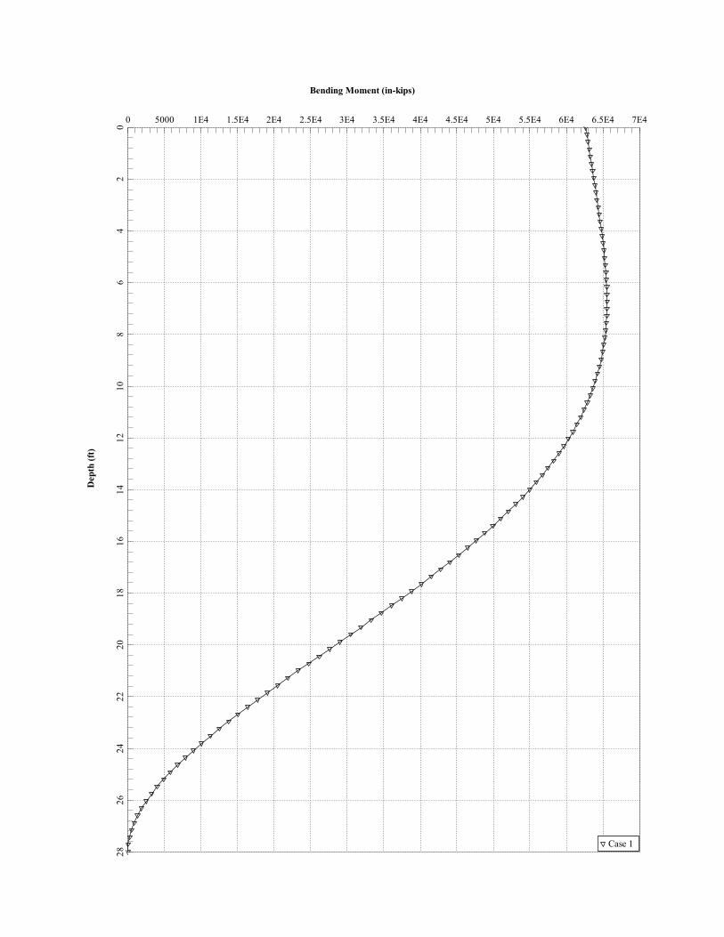
Bending Moment (in-kips)D
epth
(ft)
0 5000 1E4 1.5E4 2E4 2.5E4 3E4 3.5E4 4E4 4.5E4 5E4 5.5E4 6E4 6.5E4 7E40
24
68
1012
1416
1820
2224
2628
Case 1

Shear Force (kips)D
epth
(ft)
-500 -450 -400 -350 -300 -250 -200 -150 -100 -50 0 50 1000
24
68
1012
1416
1820
2224
2628
Case 1

Section 1 - RFDS GENERAL INFORMATIONRFDS NAME: CTU2102 DATE: 06/30/2014 RF DESIGN ENG: Renz C. Bautista
ISSUE: Bronze Standard Approved? (Y/N): Yes RF DESIGN PHONE: 508-271-8396
REVISION: Final RF MANAGER: Cameron Syme RF DESIGN EMAIL: [email protected]
INITIATIVE /PROJECT:
LTE 3C - WCS. Bronze Standard.
RF PERF ENG: RFDS PROGRAM TYPE: 2016 LTE Next Carrier
RF PERF PHONE: RFDS TECHNOLOGY: LTE 3C
RF PERF EMAIL: State: Final
TRIDENT: Status: Approved
GSM FREQUENCY: 850 RFDS ID: 871350
UMTS FREQUENCY: 850, 1900 RFDS Version: 2.00
LTE FREQUENCY: 700, 1900, WCS Created By: cb6561
Date Created: 9/25/2015 3:27:22 PM
Date Updated: 11/19/2015 11:24:31 AM
Updated By: mm093q
a
I-PLAN JOB # 1: NER-RCTB-15-03240 IPLAN PRD GRP || SUB GRP #1: LTE Next Carrier || LTE 3C
I-PLAN JOB # 2: IPLAN PRD GRP || SUB GRP #2:
I-PLAN JOB # 3: IPLAN PRD GRP || SUB GRP #3:
I-PLAN JOB # 4: IPLAN PRD GRP || SUB GRP #4:
Section 2 - LOCATION INFORMATIONUSID: 100184 FA LOCATION CODE: 10128691 LOCATION NAME: GREENWICH PERRYRIDGE RD TWR
REGION: NORTHEAST MARKET CLUSTER: NEW ENGLAND MARKET: CONNECTICUT
ADDRESS: 5 PERRYRIDGE ROAD DUP CITY: GREENWICH STATE: CT
ZIP CODE: 06830 COUNTY: FAIRFIELD MSA / RSA:
LATITUDE (D-M-S): 41d 2m 2.16996s LONGITUDE (D-M-S): -73d -37m -50.99988s LAT (DEC. DEG.): 41.0339361
DIRECTIONS, ACCESS AND
EQUIPMENT LOCATION:
CTL02102
FROM ROUTE 15, MERRITT PARKWAY: EXIT 31 NORTH STREET, SOUTH (GREENWICH), TAKE NORTH STREET TO END, APPROX. 4 MILES. TURN RIGHT ON MAPLE AND IMMEDIATE LEFT ON PATTERSON
AVE. TAKE 3RD LEFT ONTO PERRYRIDGE ROAD. HOSPITAL ON RIGHT (LESS THEN 1/2 MILE). ACCESS ESCALATION CONTACT: STEVE CARBERY - FACILITIES DIRECTOR (203) 863-3000.
WEEKEND SECURITY # 860-863-3230
ORACLE PTN # 1: 2051A03JM7 PACE JOB # 1: MRCTB016739
ORACLE PTN # 2: PACE JOB # 2:
ORACLE PTN # 3: PACE JOB # 3:
ORACLE PTN # 4: PACE JOB # 4:
SEARCH RING NAME:
SEARCH RING ID: CASPR INITIATIVE # 1:
BTA: CASPR INITIATIVE # 2:
LONG (DEC. DEG.): -73.6308333 CASPR INITIATIVE # 3:
BORDER CELL WITH CONTOUR COORD: CASPR INITIATIVE # 4:
AM STUDY REQ'D (Y/N): No
FREQ COORD:
Section 3 - LICENSE COVERAGE/FILING INFORMATIONCGSA - NO FILING TRIGGERED (Yes/No): No CGSA LOSS: PCS REDUCED - UPS ZIP:
CGSA - MINOR FILING NEEDED (Yes/No):: No CGSA EXT AGMT NEEDED: PCS POPS REDUCED:
CGSA - MAJOR FILING NEEDED (Yes/No): Yes CGSA SCORECARD
UPDATED:
CGSA CALL SIGNS:
Section 4 - TOWER/REGULATORY INFORMATIONSTRUCTURE AT&T OWNED?: No GROUND ELEVATION (ft): 0 STRUCTURE TYPE: MONOPOLE
ADDITIONAL REGULATORY?: No HEIGHT OVERALL (ft): 170.00 FCC ASR NUMBER:
SUB-LEASE RIGHTS?: No STRUCTURE HEIGHT (ft): 170.00
LIGHTING TYPE: NOT REQUIRED
a
MARKET LOCATION 700 MHz Band:
MARKET LOCATION 850 MHz Band:
MARKET LOCATION 1900 MHz Band:
MARKET LOCATION AWS Band:
MARKET LOCATION WCS Band:
MARKET LOCATION Future Band:
Section 5 - E-911 INFORMATION - existingPSAP NAME: PSAP ID: E911 PHASE: MPC SVC PROVIDER: LMU REQUIRED:
SECTOR A E-911
SECTOR B
SECTOR C
SECTOR D
SECTOR E
SECTOR F
OMNI
ESRN: DATE LIVE PH1: DATE LIVE PH2:
0
0
0
Section 5 - E-911 INFORMATION - finalPSAP NAME: PSAP ID: E911 PHASE: MPC SVC PROVIDER: LMU REQUIRED:
SECTOR A E-911
SECTOR B
SECTOR C
SECTOR D
SECTOR E
SECTOR F
OMNI
ESRN: DATE LIVE PH1: DATE LIVE PH2:
0
0
0

Section 6 - RBS GENERAL INFORMATION - existingGSM 1ST RBS GSM 2ND RBS UMTS 1ST RBS UMTS 2ND RBS UMTS 3RD RBS UMTS 4TH RBS UMTS 5TH RBS UMTS 6TH RBS LTE 1ST RBS LTE 2ND RBS LTE 3RD RBS LTE 4TH RBS
RBS ID: 243927 243928 243929 243930 324314 379812 362930
CTS COMMON ID: 321D2102 321P2102 CTU2102 CTV2102 CTU6102 CTV6102 CTL02102
BTA/TID: 321G 321P 321V 321U 321W 321W 321L
4-DIGIT SITE ID: 2102 2102 8102 2102 9102 06102 02102
COW OR TOY?: No No No No No No No
CELL SITE TYPE: SECTORIZED SECTORIZED SECTORIZED SECTORIZED SECTORIZED SECTORIZED SECTORIZED
SITE TYPE: MACRO-CONVENTIONAL MACRO-CONVENTIONAL MACRO-CONVENTIONAL MACRO-CONVENTIONAL MACRO-CONVENTIONAL MACRO-CONVENTIONAL MACRO-CONVENTIONAL
BTS LOCATION ID: GROUND GROUND INTERNAL INTERNAL INTERNAL INTERNAL INTERNAL
ORIGINATING CO: CINGULAR CINGULAR CINGULAR CINGULAR CINGULAR CINGULAR CINGULAR
CELLULAR NETWORK: GOLD GOLD GOLD GOLD GOLD GOLD GOLD
OPS DISTRICT: CT-SOUTH CT-SOUTH CT SOUTH-WEST CT SOUTH-WEST CT-SOUTH CT-SOUTH CT-SOUTH
RF DISTRICT: NPO TRIAGE NPO TRIAGE NPO TRIAGE NPO TRIAGE NPO TRIAGE NPO TRIAGE NPO TRIAGE
OPS ZONE: NE_CT_S_FRFD_SW_CS NE_CT_S_FRFD_SW_CS NE_CT_S_FRFD_SW_CS NE_CT_S_FRFD_SW_CS NE_CT_S_FRFD_SW_CS NE_CT_S_FRFD_SW_CS NE_CT_S_FRFD_SW_CS
RF ZONE: HOTSEAT HOTSEAT HOTSEAT HOTSEAT HOTSEAT HOTSEAT HOTSEAT
BASE STATION TYPE: BASE BASE OVERLAY OVERLAY OVERLAY OVERLAY BASE
EQUIPMENT NAME: GREENWICH HOSPITAL -
MACRO
GREENWICH HOSP MACRO
1900
GREENWICH HOSP MACRO GREENWICH HOSP MACRO GREENWICH PERRYRIDGE
RD TWR
NM RELO 2557 GREENWICH GREENWICH PERRYRIDGE
RD TWR
DISASTER PRIORITY: 0 0 0 0 3 3 3
Section 6 - RBS GENERAL INFORMATION - finalGSM 1ST RBS GSM 2ND RBS UMTS 1ST RBS UMTS 2ND RBS UMTS 3RD RBS UMTS 4TH RBS UMTS 5TH RBS UMTS 6TH RBS LTE 1ST RBS LTE 2ND RBS LTE 3RD RBS LTE 4TH RBS
RBS ID: 243927 243928 243929 243930 324314 379812 362930 RFDS_11361248
CTS COMMON ID: 321D2102 321P2102 CTU2102 CTV2102 CTU6102 CTV6102 CTL02102 CTL06102R
BTA/TID: 321G 321P 321V 321U 321W 321W 321L 321L
4-DIGIT SITE ID: 2102 2102 8102 2102 9102 06102 02102 6102
COW OR TOY?: No No No No No No No No
CELL SITE TYPE: SECTORIZED SECTORIZED SECTORIZED SECTORIZED SECTORIZED SECTORIZED SECTORIZED SECTORIZED
SITE TYPE: MACRO-CONVENTIONAL MACRO-CONVENTIONAL MACRO-CONVENTIONAL MACRO-CONVENTIONAL MACRO-CONVENTIONAL MACRO-CONVENTIONAL MACRO-CONVENTIONAL MACRO-CONVENTIONAL
BTS LOCATION ID: GROUND GROUND INTERNAL INTERNAL INTERNAL INTERNAL INTERNAL INTERNAL
ORIGINATING CO: CINGULAR CINGULAR CINGULAR CINGULAR CINGULAR CINGULAR CINGULAR CINGULAR
CELLULAR NETWORK: GOLD GOLD GOLD GOLD GOLD GOLD GOLD GOLD
OPS DISTRICT: CT-South CT-South CT-South CT-South CT-South CT-South
RF DISTRICT: NPO Triage NPO Triage NPO Triage NPO Triage NPO Triage NPO Triage NPO Triage NPO Triage
OPS ZONE: NE_CT_S_FRFD_SW_CS NE_CT_S_FRFD_SW_CS NE_CT_S_FRFD_SW_CS NE_CT_S_FRFD_SW_CS NE_CT_S_FRFD_SW_CS NE_CT_S_FRFD_SW_CS
RF ZONE: Hotseat Hotseat Hotseat Hotseat Hotseat Hotseat Hotseat Hotseat
BASE STATION TYPE: BASE BASE OVERLAY OVERLAY OVERLAY OVERLAY BASE BASE
EQUIPMENT NAME: GREENWICH HOSPITAL -
MACRO
GREENWICH HOSP MACRO
1900
GREENWICH HOSP MACRO GREENWICH HOSP MACRO GREENWICH PERRYRIDGE
RD TWR
NM RELO 2557 GREENWICH GREENWICH PERRYRIDGE
RD TWR
GREENWICH PERRYRIDGE
RD TWR
DISASTER PRIORITY: 0 0 0 0 3 3 3 3

Section 7 - RBS SPECIFIC INFORMATION - existingGSM 1ST RBS GSM 2ND RBS UMTS 1ST RBS UMTS 2ND RBS UMTS 3RD RBS UMTS 4TH RBS UMTS 5TH RBS UMTS 6TH RBS LTE 1ST RBS LTE 2ND RBS LTE 3RD RBS LTE 4TH RBS
MSC
BSC/RNC/MME POOL ID BRPTCTBSC01 BRPTCTBSC01 BRPTCT04RNC001 BRPTCT04RNC001 BRPTCT04RNC001 BRPTCT04RNC001 FF01
LAC 05010 05010 05999 05999 05999 05999
RAC
EQUIPMENT VENDOR NOKIA NOKIA ERICSSON ERICSSON ERICSSON ERICSSON ERICSSON
EQUIPMENT TYPE ULTRASITE ULTRASITE 3206 INDOOR 3206 INDOOR 3206 INDOOR 3206 INDOOR 6601 INDOOR MU
LOCATION
CABINET LOCATION
MARKET STATE CODE CT
AGPS Yes Yes Yes Yes Yes Yes Yes
NODE B NUMBER 0 0 0 0 0 0 2102
PARENT NAME BRIDGEPORT BSC 01 BRIDGEPORT BSC 01 BRIDGEPORT CT RNC001 BRIDGEPORT CT RNC001 BRIDGEPORT CT RNC001 BRIDGEPORT CT RNC001 FF01
Section 7 - RBS SPECIFIC INFORMATION - finalGSM 1ST RBS GSM 2ND RBS UMTS 1ST RBS UMTS 2ND RBS UMTS 3RD RBS UMTS 4TH RBS UMTS 5TH RBS UMTS 6TH RBS LTE 1ST RBS LTE 2ND RBS LTE 3RD RBS LTE 4TH RBS
MSC
BSC/RNC/MME POOL ID BRPTCTBSC01 BRPTCTBSC01 BRPTCT04RNC001 BRPTCT04RNC001 BRPTCT04RNC001 BRPTCT04RNC001 FF01 FF01
LAC 05010 05010 05999 05999 05999 05999
RAC
EQUIPMENT VENDOR NOKIA NOKIA ERICSSON ERICSSON ERICSSON ERICSSON ERICSSON ERICSSON
EQUIPMENT TYPE ULTRASITE ULTRASITE 3206 INDOOR 3206 INDOOR 3206 INDOOR 3206 INDOOR 6601 INDOOR MU 6601 INDOOR MU
LOCATION
CABINET LOCATION
MARKET STATE CODE CT CT
AGPS Yes Yes Yes Yes Yes Yes Yes Yes
NODE B NUMBER 0 0 0 0 0 0 2102 6102
PARENT NAME BRIDGEPORT BSC 01 BRIDGEPORT BSC 01 BRIDGEPORT CT RNC001 BRIDGEPORT CT RNC001 BRIDGEPORT CT RNC001 BRIDGEPORT CT RNC001
Section 8 - RBS INDIVIDUAL INFORMATION - existingGSM 1ST
850
GSM 1ST
1900
GSM 2ND
850
GSM 2ND
1900
UMTS 1ST
850
UMTS 1ST
1900
UMTS 2ND
850
UMTS 2ND
1900
UMTS 3RD
850
UMTS 3RD
1900
UMTS 4TH
850
UMTS 4TH
1900
UMTS 5TH
850
UMTS 5TH
1900
UMTS 6TH
850
UMTS 6TH
1900
LTE 1ST
700
LTE 1ST
850
LTE 1ST
1900
LTE 1ST
AWS
LTE 1ST
WCS
LTE 1ST
FUTURE
RBS ID: 243927 243928 243930 243929 379812 324314 379812 324314 362930 362930
CELL ID/BCF: 321D2102 321P2102 CTU2102 CTU2102 CTU6102 CTU2102 CTU6102 CTU2102 CTL02102 CTL02102
CTS COMMON ID: 321D2102 321P2102 CTV2102 CTU2102 CTV6102 CTU6102 CTV6102 CTU6102 CTL02102 CTL02102
LTE 2ND
700
LTE 2ND
850
LTE 2ND
1900
LTE 2ND
AWS
LTE 2ND
WCS
LTE 2ND
FUTURE
RBS ID:
CELL ID/BCF:
CTS COMMON ID:
Section 8 - RBS INDIVIDUAL INFORMATION - finalGSM 1ST
850
GSM 1ST
1900
GSM 2ND
850
GSM 2ND
1900
UMTS 1ST
850
UMTS 1ST
1900
UMTS 2ND
850
UMTS 2ND
1900
UMTS 3RD
850
UMTS 3RD
1900
UMTS 4TH
850
UMTS 4TH
1900
UMTS 5TH
850
UMTS 5TH
1900
UMTS 6TH
850
UMTS 6TH
1900
LTE 1ST
700
LTE 1ST
850
LTE 1ST
1900
LTE 1ST
AWS
LTE 1ST
WCS
LTE 1ST
FUTURE
RBS ID: 243927 243928 243930 243929 379812 324314 379812 324314 362930 362930 362930
CELL ID/BCF: 321D2102 321P2102 CTU2102 CTU2102 CTU6102 CTU2102 CTU6102 CTU2102 CTL02102 CTL02102 CTL02102
CTS COMMON ID: 321D2102 321P2102 CTV2102 CTU2102 CTV6102 CTU6102 CTV6102 CTU6102 CTL02102 CTL02102 CTL02102
LTE 2ND
700
LTE 2ND
850
LTE 2ND
1900
LTE 2ND
AWS
LTE 2ND
WCS
LTE 2ND
FUTURE
RBS ID: RFDS_113612
48
RFDS_113615
34
RFDS_113615
68
CELL ID/BCF: CTL06102R CTL06102R CTL06102R
CTS COMMON ID: CTL06102R CTL06102R CTL06102R

Section 9 - SOFT SECTOR ID - existing
GSM 1ST
850
GSM 1ST
1900
GSM 2ND
850
GSM 2ND
1900
UMTS 1ST
850
UMTS 1ST
1900
UMTS 2ND
850
UMTS 2ND
1900
UMTS 3RD
850
UMTS 3RD
1900
UMTS 4TH
850
UMTS 4TH
1900
UMTS 5TH
850
UMTS 5TH
1900
UMTS 6TH
850
UMTS 6TH
1900
LTE 1ST
700
LTE 1ST
850
LTE 1ST
1900
LTE 1ST
AWS
LTE 1ST
WCS
LTE 1ST
FUTURE
USEID (excluding Hard Sector) 100184.850.25
G.1
100184.1900.2
5G.1
100184.850.3G
.1
100184.1900.3
G.1
100184.850.3G
.2
100184.1900.3
G.3
100184.850.3G
.3
100184.1900.3
G.4
100184.700.4G
.1
100184.1900.4
G.1
SECTOR A SOFT SECTOR ID 321G21021 CTV21021 CTU21027 CTV2102A CTU61024 CTU61027 CTL02102_7A_
1
CTL02102_9A_
1
SECTOR B 321G21022 321P21022 CTV21022 CTU21028 CTU61025 CTV2102B CTU61028 CTL02102_7B_
1
CTL02102_9B_
1
SECTOR C 321G21023 CTV21023 CTU21029 CTU61026 CTV2102C CTU61029 CTL02102_7C_
1
CTL02102_9C_
1
SECTOR D
SECTOR E
SECTOR F
OMNI
LTE 2ND
700
LTE 2ND
850
LTE 2ND
1900
LTE 2ND
AWS
LTE 2ND
WCS
LTE 2ND
FUTURE
USEID (excluding Hard Sector)
SECTOR A SOFT SECTOR ID
SECTOR B
SECTOR C
SECTOR D
SECTOR E
SECTOR F
OMNI
Section 9 - SOFT SECTOR ID - final
GSM 1ST
850
GSM 1ST
1900
GSM 2ND
850
GSM 2ND
1900
UMTS 1ST
850
UMTS 1ST
1900
UMTS 2ND
850
UMTS 2ND
1900
UMTS 3RD
850
UMTS 3RD
1900
UMTS 4TH
850
UMTS 4TH
1900
UMTS 5TH
850
UMTS 5TH
1900
UMTS 6TH
850
UMTS 6TH
1900
LTE 1ST
700
LTE 1ST
850
LTE 1ST
1900
LTE 1ST
AWS
LTE 1ST
WCS
LTE 1ST
FUTURE
USEID (excluding Hard Sector) 100184.850.25
G.1
100184.1900.2
5G.1
100184.850.3G
.1
100184.1900.3
G.1
100184.850.3G
.2
100184.1900.3
G.3
100184.850.3G
.3
100184.1900.3
G.4
100184.700.4G
.1
100184.1900.4
G.1
100184.WCS.4
G.111
SECTOR A SOFT SECTOR ID 321G21021 CTV21021 CTU21027 CTV2102A CTU61024 CTU61027 CTL02102_7A_
1
CTL02102_9A_
1
CTL02102_3A_
1
SECTOR B 321G21022 321P21022 CTV21022 CTU21028 CTU61025 CTV2102B CTU61028
SECTOR C 321G21023 CTV21023 CTU21029 CTU61026 CTV2102C CTU61029 CTL02102_7C_
1
CTL02102_9C_
1
CTL02102_3C_
1
SECTOR D
SECTOR E
SECTOR F
OMNI
LTE 2ND
700
LTE 2ND
850
LTE 2ND
1900
LTE 2ND
AWS
LTE 2ND
WCS
LTE 2ND
FUTURE
USEID (excluding Hard Sector) 100184.700.4G
.222
100184.1900.4
G.222
100184.WCS.4
G.222
SECTOR A SOFT SECTOR ID
SECTOR B CTL06102_7B_
1
CTL06102_9B_
1
CTL06102_3B_
1
SECTOR C
SECTOR D
SECTOR E
SECTOR F
OMNI

Section 9 - SOFT SECTOR CELL NUMBER - existing
GSM 1ST
850
GSM 1ST
1900
GSM 2ND
850
GSM 2ND
1900
UMTS 1ST
850
UMTS 1ST
1900
UMTS 2ND
850
UMTS 2ND
1900
UMTS 3RD
850
UMTS 3RD
1900
UMTS 4TH
850
UMTS 4TH
1900
UMTS 5TH
850
UMTS 5TH
1900
UMTS 6TH
850
UMTS 6TH
1900
LTE 1ST
700
LTE 1ST
850
LTE 1ST
1900
LTE 1ST
AWS
LTE 1ST
WCS
LTE 1ST
FUTURE
USEID (excluding Hard Sector) 100184.850.25
G.1
100184.1900.2
5G.1
100184.850.3G
.1
100184.1900.3
G.1
100184.850.3G
.2
100184.1900.3
G.3
100184.850.3G
.3
100184.1900.3
G.4
100184.700.4G
.1
100184.1900.4
G.1
SECTOR A CELL NUMBER 15 8
SECTOR B 16 9
SECTOR C 17 10
SECTOR D
SECTOR E
SECTOR F
OMNI
LTE 2ND
700
LTE 2ND
850
LTE 2ND
1900
LTE 2ND
AWS
LTE 2ND
WCS
LTE 2ND
FUTURE
USEID (excluding Hard Sector)
SECTOR A CELL NUMBER
SECTOR B
SECTOR C
SECTOR D
SECTOR E
SECTOR F
OMNI
Section 9 - SOFT SECTOR CELL NUMBER - final
GSM 1ST
850
GSM 1ST
1900
GSM 2ND
850
GSM 2ND
1900
UMTS 1ST
850
UMTS 1ST
1900
UMTS 2ND
850
UMTS 2ND
1900
UMTS 3RD
850
UMTS 3RD
1900
UMTS 4TH
850
UMTS 4TH
1900
UMTS 5TH
850
UMTS 5TH
1900
UMTS 6TH
850
UMTS 6TH
1900
LTE 1ST
700
LTE 1ST
850
LTE 1ST
1900
LTE 1ST
AWS
LTE 1ST
WCS
LTE 1ST
FUTURE
USEID (excluding Hard Sector) 100184.850.25
G.1
100184.1900.2
5G.1
100184.850.3G
.1
100184.1900.3
G.1
100184.850.3G
.2
100184.1900.3
G.3
100184.850.3G
.3
100184.1900.3
G.4
100184.700.4G
.1
100184.1900.4
G.1
100184.WCS.4
G.111
SECTOR A CELL NUMBER 15 8 149
SECTOR B
SECTOR C 17 10 151
SECTOR D
SECTOR E
SECTOR F
OMNI
LTE 2ND
700
LTE 2ND
850
LTE 2ND
1900
LTE 2ND
AWS
LTE 2ND
WCS
LTE 2ND
FUTURE
USEID (excluding Hard Sector) 100184.700.4G
.222
100184.1900.4
G.222
100184.WCS.4
G.222
SECTOR A CELL NUMBER
SECTOR B 16 9 150
SECTOR C
SECTOR D
SECTOR E
SECTOR F
OMNI

Section 10 - CID/SAC - existing
GSM 1ST
850
GSM 1ST
1900
GSM 2ND
850
GSM 2ND
1900
UMTS 1ST
850
UMTS 1ST
1900
UMTS 2ND
850
UMTS 2ND
1900
UMTS 3RD
850
UMTS 3RD
1900
UMTS 4TH
850
UMTS 4TH
1900
UMTS 5TH
850
UMTS 5TH
1900
UMTS 6TH
850
UMTS 6TH
1900
SECTOR A CID/SAC 21021 21021 21027 21024 61024 61027
SECTOR B 21022 21022 21022 21028 61025 21025 61028
SECTOR C 21023 21023 21029 61026 21026 61029
SECTOR D
SECTOR E
SECTOR F
OMNI
Section 10 - CID/SAC - final
GSM 1ST
850
GSM 1ST
1900
GSM 2ND
850
GSM 2ND
1900
UMTS 1ST
850
UMTS 1ST
1900
UMTS 2ND
850
UMTS 2ND
1900
UMTS 3RD
850
UMTS 3RD
1900
UMTS 4TH
850
UMTS 4TH
1900
UMTS 5TH
850
UMTS 5TH
1900
UMTS 6TH
850
UMTS 6TH
1900
SECTOR A CID/SAC 21021 21021 21027 21024 61024 61027
SECTOR B 21022 21022 21022 21028 61025 21025 61028
SECTOR C 21023 21023 21029 61026 21026 61029
SECTOR D
SECTOR E
SECTOR F
OMNI
Section 11 - CURRENT RADIO COUNTS existing
GSM 1ST
850
GSM 1ST
1900
GSM 2ND
850
GSM 2ND
1900
UMTS 1ST
850
UMTS 1ST
1900
UMTS 2ND
850
UMTS 2ND
1900
UMTS 3RD
850
UMTS 3RD
1900
UMTS 4TH
850
UMTS 4TH
1900
UMTS 5TH
850
UMTS 5TH
1900
UMTS 6TH
850
UMTS 6TH
1900
LTE 1ST
700
LTE 1ST
850
LTE 1ST
1900
LTE 1ST
AWS
LTE 1ST
WCS
LTE 1ST
FUTURE
SECTOR A RADIO COUNTS
SECTOR B
SECTOR C
SECTOR D
SECTOR E
SECTOR F
OMNI
LTE 2ND
700
LTE 2ND
850
LTE 2ND
1900
LTE 2ND
AWS
LTE 2ND
WCS
LTE 2ND
FUTURE
SECTOR A RADIO COUNTS
SECTOR B
SECTOR C
SECTOR D
SECTOR E
SECTOR F
OMNI

Section 12 - CURRENT T1 COUNTS existing
GSM 1st Cabinet GSM 2nd Cabinet UMTS 1st Cabinet UMTS 2nd Cabinet UMTS 3rd Cabinet UMTS 4th Cabinet UMTS 5th Cabinet UMTS 6th Cabinet LTE 1st Cabinet LTE 2nd Cabinet LTE 3rd Cabinet LTE 4th Cabinet
# T1s
LINK PROFILE
RF COMBINING
FIBER or ETHERNET?
Tx Board Model
Tx Board QTY
RAX/ECU Board Model
RAX/ECU Board QTY
BBU Board Model
BBU Board QTY
RRU - location
FIBER JUMPER
DC CABLE
DC/Fiber Dem. Box
Bundled Fiber Cable
Bundled DC Cable
Section 13 - NEW/PROPOSED RADIO COUNTS
GSM 1ST
850
GSM 1ST
1900
GSM 2ND
850
GSM 2ND
1900
UMTS 1ST
850
UMTS 1ST
1900
UMTS 2ND
850
UMTS 2ND
1900
UMTS 3RD
850
UMTS 3RD
1900
UMTS 4TH
850
UMTS 4TH
1900
UMTS 5TH
850
UMTS 5TH
1900
UMTS 6TH
850
UMTS 6TH
1900
LTE 1ST
700
LTE 1ST
850
LTE 1ST
1900
LTE 1ST
AWS
LTE 1ST
WCS
LTE 1ST
FUTURE
SECTOR A RADIO COUNTS
SECTOR B
SECTOR C
SECTOR D
SECTOR E
SECTOR F
OMNI
LTE 2ND
700
LTE 2ND
850
LTE 2ND
1900
LTE 2ND
AWS
LTE 2ND
WCS
LTE 2ND
FUTURE
SECTOR A RADIO COUNTS
SECTOR B
SECTOR C
SECTOR D
SECTOR E
SECTOR F
OMNI
Section 14 - NEW/PROPOSED T1 COUNTS
GSM 1st Cabinet GSM 2nd Cabinet UMTS 1st Cabinet UMTS 2nd Cabinet UMTS 3rd Cabinet UMTS 4th Cabinet UMTS 5th Cabinet UMTS 6th Cabinet LTE 1st Cabinet LTE 2nd Cabinet LTE 3rd Cabinet LTE 4th Cabinet
# T1s
LINK PROFILE
RF COMBINING
FIBER or ETHERNET?
Tx Board Model
Tx Board QTY
RAX/ECU Board Model
RAX/ECU Board QTY
BBU Board Model
BBU Board QTY
RRU - location
FIBER JUMPER
DC CABLE
DC/Fiber Dem. Box
Bundled Fiber Cable
Bundled DC Cable

Section 15A - CURRENT SECTOR/CELL INFORMATION - SECTOR A (OR OMNI)ANTENNA COMMON FIELDS ANTENNA POSITION 1 ANTENNA POSITION 2 ANTENNA POSITION 3 ANTENNA POSITION 4 ANTENNA POSITION 5 ANTENNA POSITION 6 ANTENNA POSITION 7
ANTENNA MAKE - MODEL 7770.00.850.02 7770.00.850.02 P65-16-XLH-RR
ANTENNA VENDOR POWERWAVE POWERWAVE Powerwave
ANTENNA SIZE (H x W x D) 72X12X6
ANTENNA WEIGHT 64
AZIMUTH 0 0 30
MAGNETIC DECLINATION
RADIATION CENTER (feet) 134 134 134
ANTENNA TIP HEIGHT
MECHANICAL DOWNTILT 0 0 0
FEEDER AMOUNT 2 2
Antenna RET Motor (QTY/MODEL) 2 Powerwave 7020 (DB) 2 Powerwave 7020 (DB) Internal
SURGE ARRESTOR (QTY/MODEL) 1 Squid
DIPLEXER (QTY/MODEL) 2 Powerwave/LGP 21901 4 Powerwave/LGP 21901
DUPLEXER (QTY/MODEL)
Antenna RET CONTROL UNIT (QTY/MODEL ) 1 Kathrein / 860-10006 1 Kathrein / 860-10006 LTE RRH
DC BLOCK (QTY/MODEL)
TMA/LNA (QTY/MODEL) 2Pwav LGP21401 Single
1900 w/ 850BP
CURRENT INJECTORS FOR TMA (QTY/MODEL ) 2 Polyphaser 1000860
PDU FOR TMAS (QTY/MODEL ) 1 LGP12104
FILTER (QTY/MODEL)
RRH - 700 band (QTY/MODEL) 1 RRUS-11
RRH - 850 band (QTY/MODEL)
RRH - 1900 band (QTY/MODEL) 1 RRUS-11
RRH - AWS band (QTY/MODEL)
RRH - WCS band (QTY/MODEL)
Additional RRH #1 - any band (QTY/MODEL)
Additional RRH #2 - any band (QTY/MODEL)
Additional Component1 (QTY/MODEL)
Additional Component2 (QTY/MODEL)
Additional Component3 (QTY/MODEL)
Local Market Note1Install and commission RRUS-11 on Antenna 4 for the implementation of LTE 2C 1900."If CSRF exits,remove the CSRF connections & connect it straight."
Local Market Note2
Local Market Note3
a
PORT SPECIFIC FIELDS PORT NUMBER USEID (CSSng) USEID (Atoll) ATOLL TXID ATOLL CELL IDTX/RX
?TECHNOLOGY/FREQUENCY
ANTENNA
ATOLL
ANTENNA
GAIN
ELECTRICAL
AZIMUTH
ELECTRICAL
TILT
RRH
LOCATION
(Top/Bottom/
Integrated/No
ne)
FEEDERS
TYPE
FEEDER
LENGTH
(feet)
RXAIT KIT
MODULE?
TRIPLEXER
or LLC (QTY)
TRIPLEXER
or LLC
(MODEL)
SCPA/MCPA
MODULE?
HATCHPLAT
E POWER
(Watts)
ERP
(Watts)
CABLE
NUMBER
CABLE
ID
(CSSNG)
ANTENNA POSITION 1
PORT 1 100184.A.850.3G.1 CTV21021 UMTS 850 7770.00.850.02 13.5 2 NoneCommscope 1-5/8
(850)160 NO
PORT 2 100184.A.850.3G.2 CTV2102A UMTS 850 7770.00.850.02 13.5 2 NoneCommscope 1-5/8
(850)160 NO
PORT 3 100184.A.1900.3G.1 CTU61027 UMTS 1900 7770.00.1900.00 15.5 0 NoneCommscope 1-5/8
(1900)160 NO
PORT 4 100184.A.1900.3G.2 CTU61024 UMTS 1900 7770.00.1900.00 15.5 0 NoneCommscope 1-5/8
(1900)160 NO
a
ANTENNA POSITION 3 PORT 1 100184.A.850.25G.1 321G21021 GSM 850 7770.00.850.02 13.5 2 NoneCommscope 1-5/8
(850)160 NO 12.58 111.42
a
ANTENNA POSITION 4
PORT 1 100184.A.700.4G.1 CTL02102_7A_1 LTE 700P65-16-XLH-
RR_716MHz_02DT14.8 2 Top FIBER 0
PORT 3 100184.A.1900.4G.1 CTL02102_9A_1 LTE 1900P65-16-XLH-
RR_1930MHz_03DT14.93 3 Top FIBER 0

Section 15B - CURRENT SECTOR/CELL INFORMATION - SECTOR BANTENNA COMMON FIELDS ANTENNA POSITION 1 ANTENNA POSITION 2 ANTENNA POSITION 3 ANTENNA POSITION 4 ANTENNA POSITION 5 ANTENNA POSITION 6 ANTENNA POSITION 7
ANTENNA MAKE - MODEL 7770.00.850.04 7770.00.850.04 P65-16-XLH-RR
ANTENNA VENDOR POWERWAVE POWERWAVE Powerwave
ANTENNA SIZE (H x W x D) 72X12X6
ANTENNA WEIGHT 64
AZIMUTH 100 100 150
MAGNETIC DECLINATION
RADIATION CENTER (feet) 134 134 134
ANTENNA TIP HEIGHT
MECHANICAL DOWNTILT 0 0 0
FEEDER AMOUNT 2 2
Antenna RET Motor (QTY/MODEL) 2 Powerwave 7020 (DB) 2 Powerwave 7020 (DB) Internal
SURGE ARRESTOR (QTY/MODEL) 1 Squid
DIPLEXER (QTY/MODEL) 2 Powerwave/LGP 21901 4 Powerwave/LGP 21901
DUPLEXER (QTY/MODEL)
Antenna RET CONTROL UNIT (QTY/MODEL ) 1 Kathrein / 860-10006 1 Kathrein / 860-10006 LTE RRH
DC BLOCK (QTY/MODEL)
TMA/LNA (QTY/MODEL) 2Pwav LGP21401 Single
1900 w/ 850BP
CURRENT INJECTORS FOR TMA (QTY/MODEL ) 2 Polyphaser 1000860
PDU FOR TMAS (QTY/MODEL ) 1 LGP12104
FILTER (QTY/MODEL)
RRH - 700 band (QTY/MODEL) 1 RRUS-11
RRH - 850 band (QTY/MODEL)
RRH - 1900 band (QTY/MODEL) 1 RRUS-11
RRH - AWS band (QTY/MODEL)
RRH - WCS band (QTY/MODEL)
Additional RRH #1 - any band (QTY/MODEL)
Additional RRH #2 - any band (QTY/MODEL)
Additional Component1 (QTY/MODEL)
Additional Component2 (QTY/MODEL)
Additional Component3 (QTY/MODEL)
Local Market Note1Install and commission RRUS-11 on Antenna 4 for the implementation of LTE 2C 1900."If CSRF exits,remove the CSRF connections & connect it straight."
Local Market Note2
Local Market Note3
a
PORT SPECIFIC FIELDS PORT NUMBER USEID (CSSng) USEID (Atoll) ATOLL TXID ATOLL CELL IDTX/RX
?TECHNOLOGY/FREQUENCY
ANTENNA
ATOLL
ANTENNA
GAIN
ELECTRICAL
AZIMUTH
ELECTRICAL
TILT
RRH
LOCATION
(Top/Bottom/
Integrated/No
ne)
FEEDERS
TYPE
FEEDER
LENGTH
(feet)
RXAIT KIT
MODULE?
TRIPLEXER
or LLC (QTY)
TRIPLEXER
or LLC
(MODEL)
SCPA/MCPA
MODULE?
HATCHPLAT
E POWER
(Watts)
ERP
(Watts)
CABLE
NUMBER
CABLE
ID
(CSSNG)
ANTENNA POSITION 1
PORT 1 100184.B.850.3G.1 CTV21022 UMTS 850 7770.00.850.04 13.5 4 NoneCommscope 1-5/8
(850)160 NO
PORT 2 100184.B.850.3G.2 CTV2102B UMTS 850 7770.00.850.04 13.5 4 NoneCommscope 1-5/8
(850)160 NO
PORT 3 100184.B.1900.3G.1 CTU61028 UMTS 1900 7770.00.1900.02 15.5 2 NoneCommscope 1-5/8
(1900)160 NO
PORT 4 100184.B.1900.3G.2 CTU61025 UMTS 1900 7770.00.1900.02 15.5 2 NoneCommscope 1-5/8
(1900)160 NO
a
ANTENNA POSITION 3 PORT 1 100184.B.850.25G.1 321G21022 GSM 850 7770.00.850.04 13.5 4 NoneCommscope 1-5/8
(850)160 NO 12.58 111.42
a
ANTENNA POSITION 4
PORT 1 100184.B.700.4G.1 CTL02102_7B_1 LTE 700P65-16-XLH-
RR_716MHz_08DT14.8 8 Top FIBER 0
PORT 3 100184.B.1900.4G.1 CTL02102_9B_1 LTE 1900P65-16-XLH-
RR_1930MHz_06DT14.93 6 Top FIBER 0

Section 15C - CURRENT SECTOR/CELL INFORMATION - SECTOR CANTENNA COMMON FIELDS ANTENNA POSITION 1 ANTENNA POSITION 2 ANTENNA POSITION 3 ANTENNA POSITION 4 ANTENNA POSITION 5 ANTENNA POSITION 6 ANTENNA POSITION 7
ANTENNA MAKE - MODEL 7770.00.850.07 7770.00.850.07 P65-16-XLH-RR
ANTENNA VENDOR POWERWAVE POWERWAVE Powerwave
ANTENNA SIZE (H x W x D) 72X12X6
ANTENNA WEIGHT 64
AZIMUTH 250 250 270
MAGNETIC DECLINATION
RADIATION CENTER (feet) 134 134 134
ANTENNA TIP HEIGHT
MECHANICAL DOWNTILT 0 0 0
FEEDER AMOUNT 2 2
Antenna RET Motor (QTY/MODEL) 2 Powerwave 7020 (DB) 2 Powerwave 7020 (DB) Internal
SURGE ARRESTOR (QTY/MODEL) 1 Squid
DIPLEXER (QTY/MODEL) 2 Powerwave/LGP 21901 4 Powerwave/LGP 21901
DUPLEXER (QTY/MODEL)
Antenna RET CONTROL UNIT (QTY/MODEL ) 1 Kathrein / 860-10006 1 Kathrein / 860-10006 LTE RRH
DC BLOCK (QTY/MODEL)
TMA/LNA (QTY/MODEL) 2Pwav LGP21401 Single
1900 w/ 850BP
CURRENT INJECTORS FOR TMA (QTY/MODEL ) 2 Polyphaser 1000860
PDU FOR TMAS (QTY/MODEL ) 1 LGP12104
FILTER (QTY/MODEL)
RRH - 700 band (QTY/MODEL) 1 RRUS-11
RRH - 850 band (QTY/MODEL)
RRH - 1900 band (QTY/MODEL) 1 RRUS-11
RRH - AWS band (QTY/MODEL)
RRH - WCS band (QTY/MODEL)
Additional RRH #1 - any band (QTY/MODEL)
Additional RRH #2 - any band (QTY/MODEL)
Additional Component1 (QTY/MODEL)
Additional Component2 (QTY/MODEL)
Additional Component3 (QTY/MODEL)
Local Market Note1Install and commission RRUS-11 on Antenna 4 for the implementation of LTE 2C 1900."If CSRF exits,remove the CSRF connections & connect it straight."
Local Market Note2
Local Market Note3
a
PORT SPECIFIC FIELDS PORT NUMBER USEID (CSSng) USEID (Atoll) ATOLL TXID ATOLL CELL IDTX/RX
?TECHNOLOGY/FREQUENCY
ANTENNA
ATOLL
ANTENNA
GAIN
ELECTRICAL
AZIMUTH
ELECTRICAL
TILT
RRH
LOCATION
(Top/Bottom/
Integrated/No
ne)
FEEDERS
TYPE
FEEDER
LENGTH
(feet)
RXAIT KIT
MODULE?
TRIPLEXER
or LLC (QTY)
TRIPLEXER
or LLC
(MODEL)
SCPA/MCPA
MODULE?
HATCHPLAT
E POWER
(Watts)
ERP
(Watts)
CABLE
NUMBER
CABLE
ID
(CSSNG)
ANTENNA POSITION 1
PORT 1 100184.C.850.3G.1 CTV21023 UMTS 850 7770.00.850.07 13.5 7 NoneCommscope 1-5/8
(850)160 NO
PORT 2 100184.C.850.3G.2 CTV2102C UMTS 850 7770.00.850.07 13.5 7 NoneCommscope 1-5/8
(850)160 NO
PORT 3 100184.C.1900.3G.1 CTU61029 UMTS 1900 7770.00.1900.04 15.5 4 NoneCommscope 1-5/8
(1900)160 NO
PORT 4 100184.C.1900.3G.2 CTU61026 UMTS 1900 7770.00.1900.04 15.5 4 NoneCommscope 1-5/8
(1900)160 NO
a
ANTENNA POSITION 3 PORT 1 100184.C.850.25G.1 321G21023 GSM 850 7770.00.850.07 13.5 7 NoneCommscope 1-5/8
(850)160 NO 12.58 111.42
a
ANTENNA POSITION 4
PORT 1 100184.C.700.4G.1 CTL02102_7C_1 LTE 700P65-16-XLH-
RR_716MHz_03DT14.8 3 Top FIBER 0
PORT 3 100184.C.1900.4G.1 CTL02102_9C_1 LTE 1900P65-16-XLH-
RR_1930MHz_03DT14.93 3 Top FIBER 0

Section 16A - NEW/PROPOSED SECTOR/CELL INFORMATION - SECTOR A (OR OMNI)ANTENNA COMMON FIELDS ANTENNA POSITION 1 ANTENNA POSITION 2 ANTENNA POSITION 3 ANTENNA POSITION 4 ANTENNA POSITION 5 ANTENNA POSITION 6 ANTENNA POSITION 7
Existing Antenna?
ANTENNA MAKE - MODEL QS66512-3
ANTENNA VENDOR Quintel
ANTENNA SIZE (H x W x D) 72.0X12.0X9.6
ANTENNA WEIGHT 105
AZIMUTH 30
MAGNETIC DECLINATION
RADIATION CENTER (feet) 134
ANTENNA TIP HEIGHT
MECHANICAL DOWNTILT 0
FEEDER AMOUNT
Antenna RET Motor (QTY/MODEL) Built-in
SURGE ARRESTOR (QTY/MODEL) 1 DC Fiber Squid
DIPLEXER (QTY/MODEL) 4 CCi triplexer TPX-070821
DUPLEXER (QTY/MODEL)
Antenna RET CONTROL UNIT (QTY/MODEL ) RRH Conrtolled
DC BLOCK (QTY/MODEL)
TMA/LNA (QTY/MODEL)
CURRENT INJECTORS FOR TMA (QTY/MODEL )
PDU FOR TMAS (QTY/MODEL )
FILTER (QTY/MODEL)
RRH - 700 band (QTY/MODEL)
RRH - 850 band (QTY/MODEL)
RRH - 1900 band (QTY/MODEL) 1 RRUS-12+RRUS-A2
RRH - AWS band (QTY/MODEL)
RRH - WCS band (QTY/MODEL) 1 RRUS-32
Additional RRH #1 - any band (QTY/MODEL)
Additional RRH #2 - any band (QTY/MODEL)
Additional Component1 (QTY/MODEL)
Additional Component2 (QTY/MODEL)
Additional Component3 (QTY/MODEL)
Local Market Note1
Add LTE 3C WCS with RRUS-32 RRH on TOP as Bronze standard
Replace GSM Antenna on Pos 2 to 6' QS66512-3 Quintel 12 port Antenna
Move and Replace LTE 2C 1900 Radio from Pos 4 to Pos 2 with RRUS-12+RRUS-A2 to join LTE 3C WCS and GSM on Pos 2.
Then move position 3(GSM/LTE 1900/WCS) to pos 2 for 6' separation between future LTE carriers.
UMTS on pos 1, LTE 700 on position 4.
Add 2 CCi triplexer TPX-070821 @ bottom
Add 2 CCi triplexer TPX-070821 @ Top
Upgrade DUL to DUS 41 // Add 2nd Squid - 1 DC Fiber squid, 2 DC Trunks, 1 Fiber Trunks.
Add 2nd DUs 41 and move busiest sector beta on second Node B.
Local Market Note2
Local Market Note3
a
PORT SPECIFIC FIELDS PORT NUMBER USEID (CSSng) USEID (Atoll) ATOLL TXID ATOLL CELL IDTX/RX
?TECHNOLOGY/FREQUENCY
ANTENNA
ATOLL
ANTENNA
GAIN
ELECTRICAL
AZIMUTH
ELECTRICAL
TILT
RRH
LOCATION
(Top/Bottom/
Integrated/No
ne)
FEEDERS
TYPE
FEEDER
LENGTH
(feet)
RXAIT KIT
MODULE?
TRIPLEXER
or LLC (QTY)
TRIPLEXER
or LLC
(MODEL)
SCPA/MCPA
MODULE?
HATCHPLAT
E POWER
(Watts)
ERP
(Watts)
CABLE
NUMBER
CABLE
ID
(CSSNG)
ANTENNA POSITION 2PORT 3 100184.A.1900.4G.1 100184.A.1900.4G.1 CTL02102_9A_1 LTE 1900 QS66512-3_1948MHz_03DT 14.93 3 TOP FIBER 0 0
PORT 4 100184.A.WCS.4G.111 100184.A.WCS.4G.1 CTL02102_3A_1 LTE WCS QS66512-3_2350MHz_02DT 17.3 2 TOP FIBER 0 0

Section 16B - NEW/PROPOSED SECTOR/CELL INFORMATION - SECTOR BANTENNA COMMON FIELDS ANTENNA POSITION 1 ANTENNA POSITION 2 ANTENNA POSITION 3 ANTENNA POSITION 4 ANTENNA POSITION 5 ANTENNA POSITION 6 ANTENNA POSITION 7
Existing Antenna?
ANTENNA MAKE - MODEL QS66512-3
ANTENNA VENDOR Quintel
ANTENNA SIZE (H x W x D) 72.0X12.0X9.6
ANTENNA WEIGHT 105
AZIMUTH 150
MAGNETIC DECLINATION
RADIATION CENTER (feet) 134
ANTENNA TIP HEIGHT
MECHANICAL DOWNTILT 0
FEEDER AMOUNT
Antenna RET Motor (QTY/MODEL) Built-in
SURGE ARRESTOR (QTY/MODEL)
DIPLEXER (QTY/MODEL) 4 CCi triplexer TPX-070821
DUPLEXER (QTY/MODEL)
Antenna RET CONTROL UNIT (QTY/MODEL ) RRH Conrtolled
DC BLOCK (QTY/MODEL)
TMA/LNA (QTY/MODEL)
CURRENT INJECTORS FOR TMA (QTY/MODEL )
PDU FOR TMAS (QTY/MODEL )
FILTER (QTY/MODEL)
RRH - 700 band (QTY/MODEL)
RRH - 850 band (QTY/MODEL)
RRH - 1900 band (QTY/MODEL) 1 RRUS-12+RRUS-A2
RRH - AWS band (QTY/MODEL)
RRH - WCS band (QTY/MODEL) 1 RRUS-32
Additional RRH #1 - any band (QTY/MODEL)
Additional RRH #2 - any band (QTY/MODEL)
Additional Component1 (QTY/MODEL)
Additional Component2 (QTY/MODEL)
Additional Component3 (QTY/MODEL)
Local Market Note1
Add LTE 3C WCS with RRUS-32 RRH on TOP as Bronze standard
Replace GSM Antenna on Pos 2 to 6' QS66512-3 Quintel 12 port Antenna
Move and Replace LTE 2C 1900 Radio from Pos 4 to Pos 2 with RRUS-12+RRUS-A2 to join LTE 3C WCS and GSM on Pos 2.
Then move position 3(GSM/LTE 1900/WCS) to pos 2 for 6' separation between future LTE carriers.
UMTS on pos 1, LTE 700 on position 4.
Add 2 CCi triplexer TPX-070821 @ bottom
Add 2 CCi triplexer TPX-070821 @ Top
Upgrade DUL to DUS 41 // Add 2nd Squid - 1 DC Fiber squid, 2 DC Trunks, 1 Fiber Trunks.
Add 2nd DUs 41 and move busiest sector beta on second Node B.
Local Market Note2
Local Market Note3
a
PORT SPECIFIC FIELDS PORT NUMBER USEID (CSSng) USEID (Atoll) ATOLL TXID ATOLL CELL IDTX/RX
?TECHNOLOGY/FREQUENCY
ANTENNA
ATOLL
ANTENNA
GAIN
ELECTRICAL
AZIMUTH
ELECTRICAL
TILT
RRH
LOCATION
(Top/Bottom/
Integrated/No
ne)
FEEDERS
TYPE
FEEDER
LENGTH
(feet)
RXAIT KIT
MODULE?
TRIPLEXER
or LLC (QTY)
TRIPLEXER
or LLC
(MODEL)
SCPA/MCPA
MODULE?
HATCHPLAT
E POWER
(Watts)
ERP
(Watts)
CABLE
NUMBER
CABLE
ID
(CSSNG)
ANTENNA POSITION 2PORT 3 100184.B.1900.4G.222 100184.B.1900.4G.1 CTL02102_9B_1 LTE 1900 QS66512-3_1948MHz_03DT 14.93 3 TOP FIBER 0 0
PORT 4 100184.B.WCS.4G.222 100184.B.WCS.4G.1 CTL02102_3B_1 LTE WCS QS66512-3_2350MHz_02DT 14.8 2 TOP FIBER 0 0

Section 16C - NEW/PROPOSED SECTOR/CELL INFORMATION - SECTOR CANTENNA COMMON FIELDS ANTENNA POSITION 1 ANTENNA POSITION 2 ANTENNA POSITION 3 ANTENNA POSITION 4 ANTENNA POSITION 5 ANTENNA POSITION 6 ANTENNA POSITION 7
Existing Antenna?
ANTENNA MAKE - MODEL QS66512-3
ANTENNA VENDOR Quintel
ANTENNA SIZE (H x W x D) 72.0X12.0X9.6
ANTENNA WEIGHT 105
AZIMUTH 270
MAGNETIC DECLINATION
RADIATION CENTER (feet) 134
ANTENNA TIP HEIGHT
MECHANICAL DOWNTILT 0
FEEDER AMOUNT
Antenna RET Motor (QTY/MODEL) Built-in
SURGE ARRESTOR (QTY/MODEL)
DIPLEXER (QTY/MODEL) 4 CCi triplexer TPX-070821
DUPLEXER (QTY/MODEL)
Antenna RET CONTROL UNIT (QTY/MODEL ) RRH Conrtolled
DC BLOCK (QTY/MODEL)
TMA/LNA (QTY/MODEL)
CURRENT INJECTORS FOR TMA (QTY/MODEL )
PDU FOR TMAS (QTY/MODEL )
FILTER (QTY/MODEL)
RRH - 700 band (QTY/MODEL)
RRH - 850 band (QTY/MODEL)
RRH - 1900 band (QTY/MODEL) 1 RRUS-12+RRUS-A2
RRH - AWS band (QTY/MODEL)
RRH - WCS band (QTY/MODEL) 1 RRUS-32
Additional RRH #1 - any band (QTY/MODEL)
Additional RRH #2 - any band (QTY/MODEL)
Additional Component1 (QTY/MODEL)
Additional Component2 (QTY/MODEL)
Additional Component3 (QTY/MODEL)
Local Market Note1
Add LTE 3C WCS with RRUS-32 RRH on TOP as Bronze standard
Replace GSM Antenna on Pos 2 to 6' QS66512-3 Quintel 12 port Antenna
Move and Replace LTE 2C 1900 Radio from Pos 4 to Pos 2 with RRUS-12+RRUS-A2 to join LTE 3C WCS and GSM on Pos 2.
Then move position 3(GSM/LTE 1900/WCS) to pos 2 for 6' separation between future LTE carriers.
UMTS on pos 1, LTE 700 on position 4.
Add 2 CCi triplexer TPX-070821 @ bottom
Add 2 CCi triplexer TPX-070821 @ Top
Upgrade DUL to DUS 41 // Add 2nd Squid - 1 DC Fiber squid, 2 DC Trunks, 1 Fiber Trunks.
Add 2nd DUs 41 and move busiest sector beta on second Node B.
Local Market Note2
Local Market Note3
a
PORT SPECIFIC FIELDS PORT NUMBER USEID (CSSng) USEID (Atoll) ATOLL TXID ATOLL CELL IDTX/RX
?TECHNOLOGY/FREQUENCY
ANTENNA
ATOLL
ANTENNA
GAIN
ELECTRICAL
AZIMUTH
ELECTRICAL
TILT
RRH
LOCATION
(Top/Bottom/
Integrated/No
ne)
FEEDERS
TYPE
FEEDER
LENGTH
(feet)
RXAIT KIT
MODULE?
TRIPLEXER
or LLC (QTY)
TRIPLEXER
or LLC
(MODEL)
SCPA/MCPA
MODULE?
HATCHPLAT
E POWER
(Watts)
ERP
(Watts)
CABLE
NUMBER
CABLE
ID
(CSSNG)
ANTENNA POSITION 2PORT 3 100184.C.1900.4G.1 100184.C.1900.4G.1 CTL02102_9C_1 LTE 1900 QS66512-3_1948MHz_03DT 14.93 3 TOP FIBER 0 0
PORT 4 100184.C.WCS.4G.111 100184.C.WCS.4G.1 CTL02102_3C_1 LTE WCS QS66512-3_2350MHz_02DT 17.3 2 TOP FIBER 0 0

Section 17A - FINAL SECTOR/CELL INFORMATION - SECTOR A (OR OMNI)ANTENNA COMMON FIELDS ANTENNA POSITION 1 ANTENNA POSITION 2 ANTENNA POSITION 3 ANTENNA POSITION 4 ANTENNA POSITION 5 ANTENNA POSITION 6 ANTENNA POSITION 7
ANTENNA MAKE - MODEL 7770.00.850.02 QS66512-3 P65-16-XLH-RR
ANTENNA VENDOR POWERWAVE Quintel Powerwave
ANTENNA SIZE (H x W x D) 72.0X12.0X9.6 72X12X6
ANTENNA WEIGHT 105 64
AZIMUTH 0 30 30
MAGNETIC DECLINATION
RADIATION CENTER (feet) 134 134 134
ANTENNA TIP HEIGHT
MECHANICAL DOWNTILT 0 0 0
FEEDER AMOUNT 2 Fiber + 2 Coax
Antenna RET Motor (QTY/MODEL) 2 Powerwave 7020 (DB) Built-in Internal
SURGE ARRESTOR (QTY/MODEL) 1 DC Fiber Squid 1 DC Fiber Squid
DIPLEXER (QTY/MODEL) 2 Powerwave/LGP 21901 4 CCi triplexer TPX-070821
DUPLEXER (QTY/MODEL)
Antenna RET CONTROL UNIT (QTY/MODEL ) 1 Kathrein / 860-10006 1 RRH Conrtolled LTE RRH
DC BLOCK (QTY/MODEL)
TMA/LNA (QTY/MODEL) 2Pwav LGP21401 Single
1900 w/ 850BP
CURRENT INJECTORS FOR TMA (QTY/MODEL ) 2 Polyphaser 1000860
PDU FOR TMAS (QTY/MODEL ) 1 LGP12104
FILTER (QTY/MODEL)
RRH - 700 band (QTY/MODEL) 1 RRUS-11
RRH - 850 band (QTY/MODEL)
RRH - 1900 band (QTY/MODEL) 1 RRUS-12+RRUS-A2
RRH - AWS band (QTY/MODEL)
RRH - WCS band (QTY/MODEL) 1 RRUS-32
Additional RRH #1 - any band (QTY/MODEL)
Additional RRH #2 - any band (QTY/MODEL)
Additional Component1 (QTY/MODEL)
Additional Component2 (QTY/MODEL)
Additional Component3 (QTY/MODEL)
Local Market Note1
Add LTE 3C WCS with RRUS-32 RRH on TOP as Bronze standard
Replace GSM Antenna on Pos 2 to 6' QS66512-3 Quintel 12 port Antenna
Move and Replace LTE 2C 1900 Radio from Pos 4 to Pos 2 with RRUS-12+RRUS-A2 to join LTE 3C WCS and GSM on Pos 2.
Then move position 3(GSM/LTE 1900/WCS) to pos 2 for 6' separation between future LTE carriers.
UMTS on pos 1, LTE 700 on position 4.
Add 2 CCi triplexer TPX-070821 @ bottom
Add 2 CCi triplexer TPX-070821 @ Top
Upgrade DUL to DUS 41 // Add 2nd Squid - 1 DC Fiber squid, 2 DC Trunks, 1 Fiber Trunks.
Add 2nd DUs 41 and move busiest sector beta on second Node B.
Local Market Note2
Local Market Note3
a
PORT SPECIFIC FIELDS PORT NUMBER USEID (CSSng) USEID (Atoll) ATOLL TXID ATOLL CELL IDTX/RX
?TECHNOLOGY/FREQUENCY
ANTENNA
ATOLL
ANTENNA
GAIN
ELECTRICAL
AZIMUTH
ELECTRICAL
TILT
RRH
LOCATION
(Top/Bottom/
Integrated/No
ne)
FEEDERS
TYPE
FEEDER
LENGTH
(feet)
RXAIT KIT
MODULE?
TRIPLEXER
or LLC (QTY)
TRIPLEXER
or LLC
(MODEL)
SCPA/MCPA
MODULE?
HATCHPLAT
E POWER
(Watts)
ERP
(Watts)
CABLE
NUMBER
CABLE
ID
(CSSNG)
ANTENNA POSITION 1
PORT 1 100184.A.850.3G.1 100184.A.850.3G.1 CTV21021 UMTS 850 7770.00.850.02 13.5 2 NoneCommscope 1-5/8
(850)160 0 NO
PORT 2 100184.A.850.3G.2 100184.A.850.3G.2 CTV2102A UMTS 850 7770.00.850.02 13.5 2 NoneCommscope 1-5/8
(850)160 0 NO
PORT 3 100184.A.1900.3G.1 100184.A.1900.3G.1 CTU61027 UMTS 1900 7770.00.1900.00 15.5 0 NoneCommscope 1-5/8
(1900)160 0 NO
PORT 4100184.A.1900.3G.3,100184.
A.1900.3G.4100184.A.1900.3G.2 CTU61024
Deco
mUMTS 1900 7770.00.1900.00 15.5 0 None
Commscope 1-5/8
(1900)160 0 NO
a
ANTENNA POSITION 2
PORT 1 100184.A.850.25G.1 100184.A.850.25G.1 321G21021 GSM 850 QS66512-3_850MHz_03DT 13.5 2 NoneCommscope 1-5/8
(850)160 0 NO 12.58 111.42
PORT 3 100184.A.1900.4G.1 100184.A.1900.4G.1 CTL02102_9A_1 LTE 1900 QS66512-3_1948MHz_03DT 14.93 3 TOP FIBER 0 0
PORT 5 100184.A.WCS.4G.111 100184.A.WCS.4G.1 CTL02102_3A_1 LTE WCS QS66512-3_2350MHz_02DT 17.3 2 TOP FIBER 0 0a
ANTENNA POSITION 4 PORT 1 100184.A.700.4G.1 100184.A.700.4G.1 CTL02102_7A_1 LTE 700P65-16-XLH-
RR_716MHz_02DT14.8 2 Top FIBER 0 0

Section 17B - FINAL SECTOR/CELL INFORMATION - SECTOR BANTENNA COMMON FIELDS ANTENNA POSITION 1 ANTENNA POSITION 2 ANTENNA POSITION 3 ANTENNA POSITION 4 ANTENNA POSITION 5 ANTENNA POSITION 6 ANTENNA POSITION 7
ANTENNA MAKE - MODEL 7770.00.850.04 QS66512-3 P65-16-XLH-RR
ANTENNA VENDOR POWERWAVE Quintel Powerwave
ANTENNA SIZE (H x W x D) 72.0X12.0X9.6 72X12X6
ANTENNA WEIGHT 105 64
AZIMUTH 100 150 150
MAGNETIC DECLINATION
RADIATION CENTER (feet) 134 134 134
ANTENNA TIP HEIGHT
MECHANICAL DOWNTILT 0 0 0
FEEDER AMOUNT 2 Fiber + 2 Coax
Antenna RET Motor (QTY/MODEL) 2 Powerwave 7020 (DB) Built-in Internal
SURGE ARRESTOR (QTY/MODEL)
DIPLEXER (QTY/MODEL) 2 Powerwave/LGP 21901 4 CCi triplexer TPX-070821
DUPLEXER (QTY/MODEL)
Antenna RET CONTROL UNIT (QTY/MODEL ) 1 RRH Conrtolled LTE RRH
DC BLOCK (QTY/MODEL)
TMA/LNA (QTY/MODEL) 2Pwav LGP21401 Single
1900 w/ 850BP
CURRENT INJECTORS FOR TMA (QTY/MODEL ) 2 Polyphaser 1000860
PDU FOR TMAS (QTY/MODEL )
FILTER (QTY/MODEL)
RRH - 700 band (QTY/MODEL) 1 RRUS-11
RRH - 850 band (QTY/MODEL)
RRH - 1900 band (QTY/MODEL) 1 RRUS-12+RRUS-A2
RRH - AWS band (QTY/MODEL)
RRH - WCS band (QTY/MODEL) 1 RRUS-32
Additional RRH #1 - any band (QTY/MODEL)
Additional RRH #2 - any band (QTY/MODEL)
Additional Component1 (QTY/MODEL)
Additional Component2 (QTY/MODEL)
Additional Component3 (QTY/MODEL)
Local Market Note1
Add LTE 3C WCS with RRUS-32 RRH on TOP as Bronze standard
Replace GSM Antenna on Pos 2 to 6' QS66512-3 Quintel 12 port Antenna
Move and Replace LTE 2C 1900 Radio from Pos 4 to Pos 2 with RRUS-12+RRUS-A2 to join LTE 3C WCS and GSM on Pos 2.
Then move position 3(GSM/LTE 1900/WCS) to pos 2 for 6' separation between future LTE carriers.
UMTS on pos 1, LTE 700 on position 4.
Add 2 CCi triplexer TPX-070821 @ bottom
Add 2 CCi triplexer TPX-070821 @ Top
Upgrade DUL to DUS 41 // Add 2nd Squid - 1 DC Fiber squid, 2 DC Trunks, 1 Fiber Trunks.
Add 2nd DUs 41 and move busiest sector beta on second Node B.
Local Market Note2
Local Market Note3
a
PORT SPECIFIC FIELDS PORT NUMBER USEID (CSSng) USEID (Atoll) ATOLL TXID ATOLL CELL IDTX/RX
?TECHNOLOGY/FREQUENCY
ANTENNA
ATOLL
ANTENNA
GAIN
ELECTRICAL
AZIMUTH
ELECTRICAL
TILT
RRH
LOCATION
(Top/Bottom/
Integrated/No
ne)
FEEDERS
TYPE
FEEDER
LENGTH
(feet)
RXAIT KIT
MODULE?
TRIPLEXER
or LLC (QTY)
TRIPLEXER
or LLC
(MODEL)
SCPA/MCPA
MODULE?
HATCHPLAT
E POWER
(Watts)
ERP
(Watts)
CABLE
NUMBER
CABLE
ID
(CSSNG)
ANTENNA POSITION 1
PORT 1 100184.B.850.3G.1 100184.B.850.3G.1 CTV21022 UMTS 850 7770.00.850.04 13.5 4 NoneCommscope 1-5/8
(850)160 0 NO
PORT 2 100184.B.850.3G.3 100184.B.850.3G.2 CTV2102B UMTS 850 7770.00.850.04 13.5 4 NoneCommscope 1-5/8
(850)160 0 NO
PORT 3100184.B.1900.25G.1,100184
.B.1900.3G.1100184.B.1900.3G.1 CTU61028 UMTS 1900 7770.00.1900.02 15.5 2 None
Commscope 1-5/8
(1900)160 0 NO
PORT 4100184.B.1900.3G.3,100184.
B.1900.3G.4100184.B.1900.3G.2 CTU61025
Deco
mUMTS 1900 7770.00.1900.02 15.5 2 None
Commscope 1-5/8
(1900)160 0 NO
a
ANTENNA POSITION 2
PORT 1 100184.B.850.25G.1 100184.B.850.25G.1 321G21022 GSM 850 QS66512-3_850MHz_03DT 13.5 4 NoneCommscope 1-5/8
(850)160 0 NO 12.58 111.42
PORT 3 100184.B.1900.4G.222 100184.B.1900.4G.1 CTL02102_9B_1 LTE 1900 QS66512-3_1948MHz_03DT 14.93 3 TOP FIBER 0 0
PORT 5 100184.B.WCS.4G.222 100184.B.WCS.4G.1 CTL02102_3B_1 LTE WCS QS66512-3_2350MHz_02DT 17.3 2 TOP FIBER 0 0a
ANTENNA POSITION 4 PORT 1 100184.B.700.4G.222 100184.B.700.4G.1 CTL02102_7B_1 LTE 700P65-16-XLH-
RR_716MHz_08DT14.8 8 Top FIBER 0 0

Section 17C - FINAL SECTOR/CELL INFORMATION - SECTOR CANTENNA COMMON FIELDS ANTENNA POSITION 1 ANTENNA POSITION 2 ANTENNA POSITION 3 ANTENNA POSITION 4 ANTENNA POSITION 5 ANTENNA POSITION 6 ANTENNA POSITION 7
ANTENNA MAKE - MODEL 7770.00.850.07 QS66512-3 P65-16-XLH-RR
ANTENNA VENDOR POWERWAVE Quintel Powerwave
ANTENNA SIZE (H x W x D) 72.0X12.0X9.6 72X12X6
ANTENNA WEIGHT 105 64
AZIMUTH 250 270 270
MAGNETIC DECLINATION
RADIATION CENTER (feet) 134 134 134
ANTENNA TIP HEIGHT
MECHANICAL DOWNTILT 0 0 0
FEEDER AMOUNT 2 Fiber + 2 Coax
Antenna RET Motor (QTY/MODEL) 2 Powerwave 7020 (DB) 2 Built-in Internal
SURGE ARRESTOR (QTY/MODEL)
DIPLEXER (QTY/MODEL) 2 Powerwave/LGP 21901 4 CCi triplexer TPX-070821
DUPLEXER (QTY/MODEL)
Antenna RET CONTROL UNIT (QTY/MODEL ) 1 RRH Conrtolled LTE RRH
DC BLOCK (QTY/MODEL)
TMA/LNA (QTY/MODEL) 2Pwav LGP21401 Single
1900 w/ 850BP
CURRENT INJECTORS FOR TMA (QTY/MODEL ) 2 Polyphaser 1000860
PDU FOR TMAS (QTY/MODEL )
FILTER (QTY/MODEL)
RRH - 700 band (QTY/MODEL) 1 RRUS-11
RRH - 850 band (QTY/MODEL)
RRH - 1900 band (QTY/MODEL) 1 RRUS-12+RRUS-A2
RRH - AWS band (QTY/MODEL)
RRH - WCS band (QTY/MODEL) 1 RRUS-32
Additional RRH #1 - any band (QTY/MODEL)
Additional RRH #2 - any band (QTY/MODEL)
Additional Component1 (QTY/MODEL)
Additional Component2 (QTY/MODEL)
Additional Component3 (QTY/MODEL)
Local Market Note1
Add LTE 3C WCS with RRUS-32 RRH on TOP as Bronze standard
Replace GSM Antenna on Pos 2 to 6' QS66512-3 Quintel 12 port Antenna
Move and Replace LTE 2C 1900 Radio from Pos 4 to Pos 2 with RRUS-12+RRUS-A2 to join LTE 3C WCS and GSM on Pos 2.
Then move position 3(GSM/LTE 1900/WCS) to pos 2 for 6' separation between future LTE carriers.
UMTS on pos 1, LTE 700 on position 4.
Add 2 CCi triplexer TPX-070821 @ bottom
Add 2 CCi triplexer TPX-070821 @ Top
Upgrade DUL to DUS 41 // Add 2nd Squid - 1 DC Fiber squid, 2 DC Trunks, 1 Fiber Trunks.
Add 2nd DUs 41 and move busiest sector beta on second Node B.
Local Market Note2
Local Market Note3
a
PORT SPECIFIC FIELDS PORT NUMBER USEID (CSSng) USEID (Atoll) ATOLL TXID ATOLL CELL IDTX/RX
?TECHNOLOGY/FREQUENCY
ANTENNA
ATOLL
ANTENNA
GAIN
ELECTRICAL
AZIMUTH
ELECTRICAL
TILT
RRH
LOCATION
(Top/Bottom/
Integrated/No
ne)
FEEDERS
TYPE
FEEDER
LENGTH
(feet)
RXAIT KIT
MODULE?
TRIPLEXER
or LLC (QTY)
TRIPLEXER
or LLC
(MODEL)
SCPA/MCPA
MODULE?
HATCHPLAT
E POWER
(Watts)
ERP
(Watts)
CABLE
NUMBER
CABLE
ID
(CSSNG)
ANTENNA POSITION 1
PORT 1 100184.C.850.3G.1 100184.C.850.3G.1 CTV21023 UMTS 850 7770.00.850.07 13.5 7 NoneCommscope 1-5/8
(850)160 0 NO
PORT 2 100184.C.850.3G.3 100184.C.850.3G.2 CTV2102C UMTS 850 7770.00.850.07 13.5 7 NoneCommscope 1-5/8
(850)160 0 NO
PORT 3 100184.C.1900.3G.1 100184.C.1900.3G.1 CTU61029 UMTS 1900 7770.00.1900.04 15.5 4 NoneCommscope 1-5/8
(1900)160 0 NO
PORT 4100184.C.1900.3G.3,100184.
C.1900.3G.4100184.C.1900.3G.2 CTU61026
Deco
mUMTS 1900 7770.00.1900.04 15.5 4 None
Commscope 1-5/8
(1900)160 0 NO
a
ANTENNA POSITION 2
PORT 1 100184.C.850.25G.1 100184.C.850.25G.1 321G21023 GSM 850 QS66512-3_850MHz_07DT 13.5 7 NoneCommscope 1-5/8
(850)160 0 NO 12.58 111.42
PORT 3 100184.C.1900.4G.1 100184.C.1900.4G.1 CTL02102_9C_1 LTE 1900 QS66512-3_1948MHz_03DT 14.93 3 TOP FIBER 0 0
PORT 5 100184.C.WCS.4G.111 100184.C.WCS.4G.1 CTL02102_3C_1 LTE WCS QS66512-3_2350MHz_02DT 17.3 2 TOP FIBER 0 0a
ANTENNA POSITION 4 PORT 1 100184.C.700.4G.1 100184.C.700.4G.1 CTL02102_7C_1 LTE 700P65-16-XLH-
RR_716MHz_03DT14.8 3 Top FIBER 0 0

Diagram - Sector A Diagram File Name - CT2102_A_WCS_BrnzStand_Rev2.vsd
Atoll Site Name - CTU2102 Location Name -GREENWICH
PERRYRIDGE RD TWRMarket - CONNECTICUT Market Cluster - NEW ENGLAND
Comments:
CCITriplexer
850
Common
HIGH700
1-41-1
Antenna 2LTE PCS/WCS/GSM 850
DC Plant
2-1
2-1
Fiber/DCDemarcation Box (Squid)
Broadband12 port
800
+45/-45
- +
Broadband12 port
AWS/WCS
+45/-45
- +
RET RET
Broadband12 port
AWS/WCS
+45/-45
- +
RET
Broadband12 port
700
+45/-45
- +
RET1 2 3 4 5 6 7 8
Broadband12 port
PCS
+45/-45
- +
RET9 10
Broadband12 port
PCS
+45/-45
- +
RET11 12
LTE RRUS-32WCS
TxRx1 TxRx2
Data Out
RxA I/O
RxB I/O
RxA Out
Data In
DC
TxRx3 TxRx4
Broadband
Low
700/850+45/-45
- +
Broadband
High
2Tx/2Rx+45/-45
- +
RET RET
Fiber/DCDemarcation Box (Squid)
1-4
1-1
1-7
LTE RRUS-12PCS
TxA/RxA TxB/RxB
Data Out
RxA I/O
RxB I/O
RxA Out
Data In
DC
LTE A21900
Rx3 Rx4
DC DC
CCITriplexer
850
Common
HIGH 700
CCITriplexer
850
Common
HIGH 700
LTE RRUS-11700 (B/C)
TxA/RxA TxB/RxB
Data Out
RxA I/O
RxB I/O
RxA Out
Data In
DC
GSM DB
1900 GSM850 GSM
850 ANT A
PCSANT A
850ANT B
1900ANT B
Antenna 4LTE 700
Antenna 1UMTS 850/1900
CCITriplexer
850
Common
HIGH700
TMA BP
BroadbandLow
700/850
+45/-45
- +
BroadbandHigh
PCS/AWS
+45/-45
- +
RET RET
850 1900
BT
PDU
BT
TMA BP
850 1900
DIPLEXER
850 1900
DIPLEXER
850 1900
UMTS 1st NodeB2 x 850
FU850
ANT A850
ANT B
RxA1 RxA2 RxA3 TxB RxB1 RxB2 RxB3
RUTx RxA RxB
FU850
ANT A850
ANT B
TxA RxA1 RxA2 RxA3 TxB RxB1 RxB2 RxB3
RUTx RxA RxB
UMTS 2nd NodeB2 x 1900
FU1900
ANT A1900
ANT B
TxA RxA1 RxA2 RxA3 TxB RxB1 RxB2 RxB3
RUTx RxA RxB
FU1900
ANT A1900
ANT B
RxA1 RxA2 RxA3 TxB RxB1 RxB2
RUTx RxA RxB
RxB3
Antenna 3
MCU
Decom
CPRI CONN TBDLTE DUS 2
700-2
CPRI MUX
CPRI CONN TBDLTE DUS 1
CPRI MUX
700-AWCS-
APCS-A PCS-B
WCS-B
700-BPCS-CWCS-
C700-C

Diagram - Sector B Diagram File Name - CT2102_B_WCS_BrnzStand_Rev2.vsd
Atoll Site Name - CTU2102 Location Name -GREENWICH
PERRYRIDGE RD TWRMarket - CONNECTICUT Market Cluster - NEW ENGLAND
Comments:
CCITriplexer
850
Common
HIGH700
1-5
1-2
Antenna 2LTE PCS/WCS/GSM 850
DC Plant
2-2
2-2
Fiber/DCDemarcation Box (Squid)
Broadband12 port
800
+45/-45
- +
Broadband12 port
AWS/WCS
+45/-45
- +
RET RET
Broadband12 port
AWS/WCS
+45/-45
- +
RET
Broadband12 port
700
+45/-45
- +
RET1 2 3 4 5 6 7 8
Broadband12 port
PCS
+45/-45
- +
RET9 10
Broadband12 port
PCS
+45/-45
- +
RET11 12
LTE RRUS-32WCS
TxRx1 TxRx2
Data Out
RxA I/O
RxB I/O
RxA Out
Data In
DC
TxRx3 TxRx4
Broadband
Low
700/850+45/-45
- +
Broadband
High
2Tx/2Rx+45/-45
- +
RET RET
Fiber/DCDemarcation Box (Squid)
1-5
1-2
1-8
LTE RRUS-12PCS
TxA/RxA TxB/RxB
Data Out
RxA I/O
RxB I/O
RxA Out
Data In
DC
LTE A21900
Rx3 Rx4
DC DC
CCITriplexer
850
Common
HIGH 700
CCITriplexer
850
Common
HIGH 700
LTE RRUS-11700 (B/C)
TxA/RxA TxB/RxB
Data Out
RxA I/O
RxB I/O
RxA Out
Data In
DC
GSM DB
1900 GSM850 GSM
850 ANT A
PCSANT A
850ANT B
1900ANT B
Antenna 4LTE 700
Antenna 1UMTS 850/1900
CCITriplexer
850
Common
HIGH700
TMA BP
BroadbandLow
700/850
+45/-45
- +
BroadbandHigh
PCS/AWS
+45/-45
- +
RET RET
850 1900
BT
PDU
BT
TMA BP
850 1900
DIPLEXER
850 1900
DIPLEXER
850 1900
UMTS 1st NodeB2 x 850
FU850
ANT A850
ANT B
RxA1 RxA2 RxA3 TxB RxB1 RxB2 RxB3
RUTx RxA RxB
FU850
ANT A850
ANT B
TxA RxA1 RxA2 RxA3 TxB RxB1 RxB2 RxB3
RUTx RxA RxB
UMTS 2nd NodeB2 x 1900
FU1900
ANT A1900
ANT B
TxA RxA1 RxA2 RxA3 TxB RxB1 RxB2 RxB3
RUTx RxA RxB
FU1900
ANT A1900
ANT B
RxA1 RxA2 RxA3 TxB RxB1 RxB2
RUTx RxA RxB
RxB3
Antenna 3
MCU
Decom
CPRI CONN TBDLTE DUS 2
700-2
CPRI MUX
CPRI CONN TBDLTE DUS 1
CPRI MUX
700-AWCS-
APCS-A PCS-B
WCS-B
700-BPCS-CWCS-
C700-C

Diagram - Sector C Diagram File Name - CT2102_C_WCS_BrnzStand_Rev2.vsd
Atoll Site Name - CTU2102 Location Name -GREENWICH
PERRYRIDGE RD TWRMarket - CONNECTICUT Market Cluster - NEW ENGLAND
Comments:
CCITriplexer
850
Common
HIGH700
1-61-3
Antenna 2LTE PCS/WCS/GSM 850
DC Plant
2-3
2-3
Fiber/DCDemarcation Box (Squid)
Broadband12 port
800
+45/-45
- +
Broadband12 port
AWS/WCS
+45/-45
- +
RET RET
Broadband12 port
AWS/WCS
+45/-45
- +
RET
Broadband12 port
700
+45/-45
- +
RET1 2 3 4 5 6 7 8
Broadband12 port
PCS
+45/-45
- +
RET9 10
Broadband12 port
PCS
+45/-45
- +
RET11 12
LTE RRUS-32WCS
TxRx1 TxRx2
Data Out
RxA I/O
RxB I/O
RxA Out
Data In
DC
TxRx3 TxRx4
Broadband
Low
700/850+45/-45
- +
Broadband
High
2Tx/2Rx+45/-45
- +
RET RET
Fiber/DCDemarcation Box (Squid)
1-6
1-3
1-9
LTE RRUS-12PCS
TxA/RxA TxB/RxB
Data Out
RxA I/O
RxB I/O
RxA Out
Data In
DC
LTE A21900
Rx3 Rx4
DC DC
CCITriplexer
850
Common
HIGH 700
CCITriplexer
850
Common
HIGH 700
LTE RRUS-11700 (B/C)
TxA/RxA TxB/RxB
Data Out
RxA I/O
RxB I/O
RxA Out
Data In
DC
GSM DB
1900 GSM850 GSM
850 ANT A
PCSANT A
850ANT B
1900ANT B
Antenna 4LTE 700
Antenna 1UMTS 850/1900
CCITriplexer
850
Common
HIGH700
TMA BP
BroadbandLow
700/850
+45/-45
- +
BroadbandHigh
PCS/AWS
+45/-45
- +
RET RET
850 1900
BT
PDU
BT
TMA BP
850 1900
DIPLEXER
850 1900
DIPLEXER
850 1900
UMTS 1st NodeB2 x 850
FU850
ANT A850
ANT B
RxA1 RxA2 RxA3 TxB RxB1 RxB2 RxB3
RUTx RxA RxB
FU850
ANT A850
ANT B
TxA RxA1 RxA2 RxA3 TxB RxB1 RxB2 RxB3
RUTx RxA RxB
UMTS 2nd NodeB2 x 1900
FU1900
ANT A1900
ANT B
TxA RxA1 RxA2 RxA3 TxB RxB1 RxB2 RxB3
RUTx RxA RxB
FU1900
ANT A1900
ANT B
RxA1 RxA2 RxA3 TxB RxB1 RxB2
RUTx RxA RxB
RxB3
Antenna 3
MCU
Decom
CPRI CONN TBDLTE DUS 2
700-2
CPRI MUX
CPRI CONN TBDLTE DUS 1
CPRI MUX
700-AWCS-
APCS-A PCS-B
WCS-B
700-BPCS-CWCS-
C700-C

WORKFLOW SUMMARY
DateFROM
State / Status
FROM
ATTUID
TO
State / Status
TO
ATTUIDOperation Comments
09/28/2015 Preliminary / In Progress cb6561Preliminary / Submitted for
ApprovalNA515M Promote
10/08/2015Preliminary / Submitted for
ApprovalNA515M Preliminary / Approved BG144B Promote
11/17/2015 Preliminary / Approved BG144B Final / RF Approval om636a Promote
11/20/2015 Final / RF Approval om636a Final / RF Approval MM093Q Re-Assign
11/20/2015 Final / RF Approval MM093Q Final / Approved BG144B Promote LTE Final RFDS

QS66512-3
6ft 65o XXX MultiServTM 12-Port Antenna
2x698-787MHz / 2x824-894MHz / 2x1850-1990MHz / 2x1850-1990MHz / 2x1695-1780+2110-2400MHz / 2x1695-1780+2110-2400MHz
Quintel Product Datasheet QS66512-3 (700-2400 6ft 65deg) July 2015 (Rev 5.4).docx
The Quintel MultiServ
TM Multiband 12 Port Antenna with patented QTilt™ technology uniquely delivers six independent services in a
single slim-line antenna. This enables existing antenna network sites to be upgraded constraint free to add new services such as LTE for 700, 850, PCS, AWS and WCS bands with the replacement of one antenna. The QS66512-3 also provides 4x1695-1780+2110-2400MHz & 4x1850-1990MHz ports as two side-by-side (CLA-2X) arrays, each array having independent tilt to support independent service, or for connection to 2T4R/4T4R services.
1 Typical Performance across frequency and Downtilt.
Mechanical Characteristics
Dimensions L 72”(1828mm) x W 12”(304mm) x D 9.6”(245mm)
Weight (excl mounting brackets) 112lbs (50.8kg)
No. of Connectors 12x 4.3-10.0 DIN Female Long Neck
Max Wind Speed 150mph (67m/s)
Equivalent Flat Plate Area 2.96ft2 (0.275m
2)
Wind Load @160km/h (45m/s) Front: 587N (132 lbs), Side: 382N (86 lbs)
Operating Temperature -40°C to +65°C
Electrical Characteristics 2x Ports
1&2
2x Ports
3&4
4x Ports
5-8
4 Ports
9-12
Operating Frequency (MHz 698-787 824-894 1695-1780 and 2110-2400 1850-1990
698-787 824-894 1695-1780 2110-2180 2300-2400 1850-1990
Azimuth beamwidth1 68
O 67
O 69
O 63
O 58
O 69
O
Elevation beamwidth1 12
O 10
O 6.5
O 5.5
O 4.5
O 5.5
O
Gain1
(dBi) 13.0 13.5 16.0 16.5 17.0 16.0
Polarization ±45
O
±45O
±45O
±45O
±45O
±45O
Electrical down-tilt range 2O-10
O 2
O-10
O
2O – 7
O
2O – 7
O
2O – 7
O
2O – 7
O
Upper SLL (20o > mainbeam)
1 -15dB -15.5dB -16dB -16dB -15dB -16dB
Front to Back Ratio(180O±10
O)1 ≥26dB ≥30dB ≥27dB ≥28dB ≥28dB ≥27dB
Port to Port isolation1 ≥28dB ≥30dB ≥28dB ≥30dB ≥30dB ≥30dB
Return loss (VSWR) 14dB(1.5) 14dB(1.5) 14dB(1.5) 14dB(1.5) 14dB (1.5) 14dB(1.5)
Squint1 <±3
O <±3
O <±3
O <±3
O <±4
O <±3
O
Tracking1 <±2.5dB <±3dB <±3dB <±3dB <±3dB <±4dB
X Polar Discrimination (at 0O) >18dB >17dB >20dB >20dB >18dB >20dB
Max Power handling (per any port) 500 watts 500 watts 250 watts 250 watts
Total Composite Power (all ports) 1750 watts
PIM (3rd
Order) (2x43dBm) >150dBc >150dBc >150dBc >150dBc
XBand PIM (3rd
Order) (2x43dBm) >157dBc
Fully Integrated RET Characteristics
AISG Standards V1.1,V 2.0 and 3GPP
Factory Default AISG 2.0
Surge immunity IEC 61000-4-5:2005 4KV(AISG PIN)
Device Type SRET Type 1
AISG Data rate 9.6 kbps
RET Configuration RET1 I/O RF Ports 1-4. RET 2 I/O RF Ports 5-12
No of connectors RET1 1in/1out. RET2 1in/1out
Connector type IEC 60130-9 (Ed 3.0)
MTBF 36,000 Operational moves
Provides 12 antenna Ports in a slim-line form factor Optimized Azimuth patterns for Min Inter-Sector Interference Industry leading Minimal Wind-Load design
700, 850, PCS, AWS & WCS bands in one antenna AISG & 3GPP compliant internal remote electrical tilt (RET) AWS & PCS Cross band PIM >157dBc
All specifications are subject to change without notice. Please
contact your Quintel representative for complete information.
R2

QS66512-3
6ft 65o XXX MultiServTM 12-Port Antenna
2x698-787MHz / 2x824-894MHz / 2x1850-1990MHz / 2x1850-1990MHz / 2x1695-1780+2110-2400MHz / 2x1695-1780+2110-2400MHz
Quintel Product Datasheet QS66512-3 (700-2400 6ft 65deg) July 2015 (Rev 5.4).docx
RF Connector Port Configuration
Ports Freq (MHz)
R1 1-2 698-787
R2 3-4 824-894
Y1 5-6 1695-1780+ 2110-2400
Y2 7-8 1695-1780+ 2110-2400
B1 9-10 1850-1990
B2 11-12 1850-1990
AISG I/O Configuration
RET Control for 700 & 850MHz
RET Device
Band RF Ports
1 700 1-2
2 850 3-4
AISG I/O Configuration RET Control for PCS & AWS/WCS
RET
Device Band RF Ports
1 AWS/WCS 5-6
2 AWS/WCS 7-8
3 PCS 9-10
4 PCS 11-12
Multiband Optimization The Quintel MultiServ
TM Multiband 12 Port Antenna is an ideal
solution for independently optimizing multiple services when rapidly introducing new technologies. Technology agnostic, each pair of ports provides flexibility for existing and future technologies such as CDMA/EVDO, GSM/EDGE, UMTS/HSPA, and LTE and advanced 2T4R and 4T4R MIMO implementations at high-bands.
The tilt of each service is controlled independently via internal RET actuators compliant to AISG1.1, AISG2.0 and 3GPP protocols. The QS66512-3 provides a total of 6 independent tilts:
1x(698-787MHz)
1x(824-894MHz)
1x Left Array (1695-1780 and 2110-2400MHz)
1x Left Array (1850-1990MHz)
1x Right Array (1695-1780 and 2110-2400MHz)
1x Right Array (1850-1990MHz)
Design Optimization
A particularly powerful characteristic of all Quintel Antennas is that our Azimuth patterns have been optimized with network design and deployment in mind. The 3dB Azimuth beamwidth is ~65
o as with
most Base Station Antennas, but we have optimized how the pattern rolls-off and where the sidelobes emerge such that there is minimal Inter-Sector Interference when 3x sectors are deployed. This means for interference limited networks, where LTE traffic is high, our antennas have been shown to deliver 25% higher capacity.
The QS66512-3 12-Port antenna has been designed for delivering best in class, maximum PIM performance. This includes using 4.3-10.0 connectors externally and internally for all array diplexing filters used with our QTilt
TM technology.
About Quintel Quintel is a leading innovator in the design, development, and delivery of network-efficient antenna solutions for wireless operators worldwide. The company’s products enable global wireless operators to independently deploy and optimize multiple air inter faces or services on a single standard antenna
platform. Quintel is the only antenna maker whose products can increase a wireless network’s capacity and provide additional services, without increasing the number or size of antennas. Quintel is headquartered in Rochester, New York with additional offices throughout North America and Europe. More information about Quintel is available at www.quintelsolutions.com.
Tel (Americas): +1 (585) 420-8720
Tel (EMEA): +44 (0)1908 231 362 [email protected]
THIS DOCUMENT PROVIDES A GENERAL DESCRIPTION OF THE PRODUCT AND SHALL NOT FORM PART OF ANY CONTRACT.
© 2015 Quintel Technology Limited. All rights reserved. Quintel and the Quintel logo are registered trademarks Quintel Technology Limited. All other
trademarks are the property of their respective owners.
RET Configuration The Quintel MultiServ
TM Multiband 12 Port Antenna has the
following Array, RF Port and AISG I/O Configurations. The 12-Port array topology consists of 3 radiating arrays: R1/R2 – 698-894MHz Y1/B1 – 1695-2400MHz Y2/B2 – 1695-2400MHz
R2

© 2015 CCI All rights reserved. Specifications are subject to change. DS-TPX070821-V1.3-150722 1
Outdoor Broadband Triplexer
TPX-070821
DATA SHEET
Low Loss
Small, lightweight
AISG 2.0 compliant from PCS/AWS port to Common port
Good Isolation
Good IM
Lightning protected
High reliability
Full 700, 850 MHz, and PCS/AWS (pre-combined) bands
Overview
Communication Components, Inc. Outdoor Broadband Triplexer combines
700 MHz, 850 MHz, and PCS/AWS band Basestation Tx/Rx signals onto a
common port. Specifically intended for use in multi-band systems with
limited feeder lines, the CCI Triplexer model TPX-070821 facilitates the
addition of new technologies including LTE to existing sites while providing a
high degree of isolation between systems. By reducing the number of feeder
lines, the cost to upgrade a site (tower loading, leasing and installation costs)
is reduced.
The CCI Outdoor Broadband Triplexer provides full band performance for
each band with low insertion loss, low Intermodulation, and high power
handling. Excellent return loss delivers the best match to the antennas and
base station, saving precious transmit power. DC and AISG pass-through
retains full RET and TMA capability utilizing CCI’s AISG suite of products.
Technical Description:
The Outdoor Broadband Triplexer consists of multiple filters to combine (or
divide) full band 700 MHz, 850 MHz and PCS/AWS signals. This tower mount
unit can be used as either a splitter or combiner to aggregate multiple bands
on a common feeder line. All RF ports are DIN 7-16 connectors. The fully
weatherproof tower mount unit incorporates a unique intelligent Bias-T
architecture which passes the DC and AISG carrier frequency from any of the
input ports to the common port while blocking the DC and AISG signals from
being re-injected into the other input ports. The unit has internal lightning
strike protection using a multi-stage surge protection circuit.
The filters have been designed to minimize insertion loss while maximizing
isolation. Particular attention has been given to the intermodulation
performance of the Broadband Diplexer to minimize any passive
intermodulation products from occurring. All DIN Connectors are fully IP68
rated and the unit body is rated for IP66.

© 2015 CCI All rights reserved. Specifications are subject to change. DS-TPX070821-V1.3-150722 3
Outdoor Broadband Triplexer
TPX-070821
SPECIFICATIONS
Mechanical
Connectors
4 × 7-16 DIN female long neck
Dimensions (w/o connectors
or brackets)(H×W×D)5.83 × 9.65 × 2.05 in. (148 × 245 × 52 mm)
Weight 7.5 lbs (3.45 kg)
Mounting Pole/Wall mounting bracket
Outdoor Broadband Triplexer Outline Drawing

EBI Consulting environmental | engineering | due diligence
21 B Street . Burlington, MA 01803 . Tel: (781) 273.2500 . Fax: (781) 273.3311
RADIO FREQUENCY EMISSIONS ANALYSIS REPORT EVALUATION OF HUMAN EXPOSURE POTENTIAL
TO NON-IONIZING EMISSIONS
AT&T Existing Facility
Site ID: CTU2102
Greenwich Perryridge Road Tower 5 Perryridge Road
Greenwich, CT 06830
February 9, 2016
EBI Project Number: 6216000623
Site Compliance Summary
Compliance Status: COMPLIANT
Site total MPE% of FCC general public
allowable limit: 33.20 %

EBI Consulting environmental | engineering | due diligence
21 B Street . Burlington, MA 01803 . Tel: (781) 273.2500 . Fax: (781) 273.3311
February 9, 2016
AT&T Mobility – New England Attn: Cameron Syme, RF Manager 550 Cochituate Road Suite 550 – 13&14 Framingham, MA 06040
Emissions Analysis for Site: CTU2102 – Greenwich Perryridge Road Tower
EBI Consulting was directed to analyze the proposed AT&T facility located at 5 Perryridge Road, Greenwich, CT, for the purpose of determining whether the emissions from the Proposed AT&T Antenna Installation located on this property are within specified federal limits.
All information used in this report was analyzed as a percentage of current Maximum Permissible Exposure (% MPE) as listed in the FCC OET Bulletin 65 Edition 97-01and ANSI/IEEE Std C95.1. The FCC regulates Maximum Permissible Exposure in units of microwatts per square centimeter (µW/cm2). The number of µW/cm2 calculated at each sample point is called the power density. The exposure limit for power density varies depending upon the frequencies being utilized. Wireless Carriers and Paging Services use different frequency bands each with different exposure limits, therefore it is necessary to report results and limits in terms of percent MPE rather than power density.
All results were compared to the FCC (Federal Communications Commission) radio frequency exposure rules, 47 CFR 1.1307(b)(1) – (b)(3), to determine compliance with the Maximum Permissible Exposure (MPE) limits for General Population/Uncontrolled environments as defined below.
General population/uncontrolled exposure limits apply to situations in which the general public may be exposed or in which persons who are exposed as a consequence of their employment may not be made fully aware of the potential for exposure or cannot exercise control over their exposure. Therefore, members of the general public would always be considered under this category when exposure is not employment related, for example, in the case of a telecommunications tower that exposes persons in a nearby residential area.
Public exposure to radio frequencies is regulated and enforced in units of microwatts per square centimeter (μW/cm2). The general population exposure limits for the 700 and 850 MHz Bands are approximately 467 μW/cm2 and 567 μW/cm2 respectively. The general population exposure limit for the 1900 MHz (PCS), 2100 MHz (AWS) and 2300 MHz (WCS) bands is 1000 μW/cm2. Because each carrier will be using different frequency bands, and each frequency band has different exposure limits, it is necessary to report percent of MPE rather than power density.

EBI Consulting environmental | engineering | due diligence
21 B Street . Burlington, MA 01803 . Tel: (781) 273.2500 . Fax: (781) 273.3311
Occupational/controlled exposure limits apply to situations in which persons are exposed as a consequence of their employment and in which those persons who are exposed have been made fully aware of the potential for exposure and can exercise control over their exposure. Occupational/controlled exposure limits also apply where exposure is of a transient nature as a result of incidental passage through a location where exposure levels may be above general population/uncontrolled limits (see below), as long as the exposed person has been made fully aware of the potential for exposure and can exercise control over his or her exposure by leaving the area or by some other appropriate means.
Additional details can be found in FCC OET 65.
CALCULATIONS
Calculations were done for the proposed AT&T Wireless antenna facility located at 5 Perryridge Road, Greenwich, CT, using the equipment information listed below. All calculations were performed per the specifications under FCC OET 65. Since AT&T is proposing highly focused directional panel antennas, which project most of the emitted energy out toward the horizon, all calculations were performed assuming a lobe representing the maximum gain of the antenna per the antenna manufactures supplied specifications, minus 10 dB, was focused at the base of the tower. For this report the sample point is the top of a 6 foot person standing at the base of the tower.
For all calculations, all equipment was calculated using the following assumptions:
1) 2 UMTS channels (8500 MHz) were considered for each sector of the proposed installation.
These Channels have a transmit power of 30 Watts per Channel. 2) 2 UMTS channels (PCS Band – 1900 MHz) were considered for each sector of the proposed
installation. These Channels have a transmit power of 30 Watts per Channel. 3) 2 GSM channels (850 MHz) were considered for each sector of the proposed installation.
These Channels have a transmit power of 30 Watts per Channel. 4) 2 LTE channels (PCS Band – 1900 MHz) were considered for each sector of the proposed
installation. These Channels have a transmit power of 60 Watts per Channel. 5) 2 LTE channels (WCS Band – 2300 MHz) were considered for each sector of the proposed
installation. These Channels have a transmit power of 60 Watts per Channel. 6) 2 LTE channels (700 MHz) were considered for each sector of the proposed installation.
These Channels have a transmit power of 60 Watts per Channel.

EBI Consulting environmental | engineering | due diligence
21 B Street . Burlington, MA 01803 . Tel: (781) 273.2500 . Fax: (781) 273.3311
7) All radios at the proposed installation were considered to be running at full power and were uncombined in their RF transmissions paths per carrier prescribed configuration. Per FCC OET Bulletin No. 65 - Edition 97-01 recommendations to achieve the maximum anticipated value at each sample point, all power levels emitting from the proposed antenna installation are increased by a factor of 2.56 to account for possible in-phase reflections from the surrounding environment. This is rarely the case, and if so, is never continuous.
8) For the following calculations the sample point was the top of a six foot person standing at
the base of the tower. The maximum gain of the antenna per the antenna manufactures supplied specifications minus 10 dB was used in this direction. This value is a very conservative estimate as gain reductions for these particular antennas are typically much higher in this direction.
9) The antennas used in this modeling are the Quintel QS66512-3, Powerwave P65-16-XLH-RR and the Powerwave 7770.00 for transmission in the 700 MHz, 850 MHz and1900 MHz (PCS) frequency bands. This is based on feedback from the carrier with regards to anticipated antenna selection. Maximum gain values for all antennas are listed in the Inventory and Power Data table below. The maximum gain of the antenna per the antenna manufactures supplied specifications, minus 10 dB, was used for all calculations. This value is a very conservative estimate as gain reductions for these particular antennas are typically much higher in this direction.
10) The antenna mounting height centerline of the proposed antennas is 134 feet above ground
level (AGL). 11) Emissions values for additional carriers were taken from the Connecticut Siting Council
active database. Values in this database are provided by the individual carriers themselves.
All calculations were done with respect to uncontrolled / general public threshold limits.

EBI Consulting environmental | engineering | due diligence
21 B Street . Burlington, MA 01803 . Tel: (781) 273.2500 . Fax: (781) 273.3311
AT&T Site Inventory and Power Data
Sector: A Sector: B Sector: C Antenna #: 1 Antenna #: 1 Antenna #: 1
Make / Model: Powerwave 7770.00 Make / Model: Powerwave 7770.00 Make / Model: Powerwave 7770.00 Gain: 11.4 / 13.4 dBd Gain: 11.4 / 13.4 dBd Gain: 11.4 / 13.4 dBd
Height (AGL): 134 feet Height (AGL): 134 feet Height (AGL): 134 feet
Frequency Bands 850 MHz / 1900 MHz (PCS) Frequency Bands 850 MHz /
1900 MHz (PCS) Frequency Bands 850 MHz / 1900 MHz (PCS)
Channel Count 4 Channel Count 4 Channel Count 4 Total TX Power(W): 120 Total TX Power(W): 120 Total TX Power(W): 120
ERP (W): 2,140.89 ERP (W): 2,140.89 ERP (W): 2,140.89 Antenna A1 MPE% 0.68 Antenna B1 MPE% 0.68 Antenna C1 MPE% 0.68
Antenna #: 2 Antenna #: 2 Antenna #: 2 Make / Model: Quintel QS66512-3 Make / Model: Quintel QS66512-3 Make / Model: Quintel QS66512-3
Gain: 11.4 / 12.78 / 15.15 dBd Gain: 11.4 / 12.78 / 15.15
dBd Gain: 11.4 / 12.78 / 15.15 dBd
Height (AGL): 134 feet Height (AGL): 134 feet Height (AGL): 134 feet
Frequency Bands 850 MHz /
1900 MHz (PCS) / 2300 MHz (WCS)
Frequency Bands 850 MHz /
1900 MHz (PCS) / 2300 MHz (WCS)
Frequency Bands 850 MHz /
1900 MHz (PCS) / 2300 MHz (WCS)
Channel Count 6 Channel Count 6 Channel Count 6 Total TX Power(W): 300 Total TX Power(W): 300 Total TX Power(W): 300
ERP (W): 7,032.37 ERP (W): 7,032.37 ERP (W): 7,032.37 Antenna A2 MPE% 1.92 Antenna B2 MPE% 1.92 Antenna C2 MPE% 1.92
Antenna #: 3 Antenna #: 3 Antenna #: 3
Make / Model: Powerwave P65-16-XLH-RR Make / Model: Powerwave
P65-16-XLH-RR Make / Model: Powerwave P65-16-XLH-RR
Gain: 12.45 dBd Gain: 12.45 dBd Gain: 12.45 dBd Height (AGL): 134 feet Height (AGL): 134 feet Height (AGL): 134 feet
Frequency Bands 700 MHz Frequency Bands 700 MHz Frequency Bands 700 MHz Channel Count 2 Channel Count 2 Channel Count 2
Total TX Power(W): 120 Total TX Power(W): 120 Total TX Power(W): 120 ERP (W): 2,109.51 ERP (W): 2,109.51 ERP (W): 2,109.51
Antenna A3 MPE% 0.82 Antenna B3 MPE% 0.82 Antenna C3 MPE% 0.82
Site Composite MPE% Carrier MPE%
AT&T – Max per sector 3.42 % Eversource 20.44 %
Verizon Wireless 3.76 % MW to Bruce 0.74 %
MW to PD 0.02 % MW to Putnam 0.74 % Trunked System 0.22 %
Mutual Aid 0.12 % CMED 0.08 %
Fire Paging 0.13 % SP Hotline 0.17 %
Sprint 0.34 % Clearwire 0.08 % T-Mobile 2.28 %
Nextel 0.66 % Site Total MPE %: 33.20 %
AT&T Sector 1 Total: 3.42 % AT&T Sector 2 Total: 3.42 % AT&T Sector 3 Total: 3.42 %
Site Total: 33.20 %

EBI Consulting environmental | engineering | due diligence
21 B Street . Burlington, MA 01803 . Tel: (781) 273.2500 . Fax: (781) 273.3311
AT&T _ Per Sector # Channels Watts ERP (Per Channel)
Height (feet)
Total Power Density
(µW/cm2)
Frequency (MHz)
Allowable MPE
(µW/cm2)
Calculated % MPE
AT&T 850 MHz UMTS 2 414.12 134 1.82 700 567 0.39 % AT&T 1900 MHz (PCS) UMTS 2 656.33 134 2.88 1900 1000 0.29 %
AT&T 850 MHz GSM 2 414.12 134 1.82 850 567 0.18 % AT&T 1900 MHz (PCS) LTE 2 1138.02 134 4.99 1900 1000 0.88 % AT&T 2300 MHz (WCS) LTE 2 1964.04 134 8.62 2300 1000 0.86 %
AT&T 700 MHz LTE 2 1054.75 134 4.63 700 467 0.82 % Total: 5.41 %

EBI Consulting environmental | engineering | due diligence
21 B Street . Burlington, MA 01803 . Tel: (781) 273.2500 . Fax: (781) 273.3311
Summary
All calculations performed for this analysis yielded results that were within the allowable limits for general public exposure to RF Emissions.
The anticipated maximum composite contributions from the AT&T facility as well as the site composite emissions value with regards to compliance with FCC’s allowable limits for general public exposure to RF Emissions are shown here:
AT&T Sector Power Density Value (%) Sector 1: 3.42 % Sector 2: 3.42 %
Sector 3 : 3.42 % AT&T Maximum Total
(per sector): 3.42 %
Site Total: 33.20 %
Site Compliance Status: COMPLIANT
The anticipated composite MPE value for this site assuming all carriers present is 33.20% of the allowable FCC established general public limit sampled at the ground level. This is based upon values listed in the Connecticut Siting Council database for existing carrier emissions.
FCC guidelines state that if a site is found to be out of compliance (over allowable thresholds), that carriers over a 5% contribution to the composite value will require measures to bring the site into compliance. For this facility, the composite values calculated were well within the allowable 100% threshold standard per the federal government.
Scott Heffernan RF Engineering Director EBI Consulting 21 B Street Burlington, MA 01803

EBI Consulting environmental | engineering | due diligence
21 B Street . Burlington, MA 01803 . Tel: (781) 273.2500 . Fax: (781) 273.3311
RADIO FREQUENCY EMISSIONS ANALYSIS REPORT EVALUATION OF HUMAN EXPOSURE POTENTIAL
TO NON-IONIZING EMISSIONS
AT&T Existing Facility
Site ID: CTU2102
Greenwich Perryridge Road Tower 5 Perryridge Road
Greenwich, CT 06830
February 9, 2016
EBI Project Number: 6216000623
Site Compliance Summary
Compliance Status: COMPLIANT
Site total MPE% of FCC general public
allowable limit: 33.20 %

EBI Consulting environmental | engineering | due diligence
21 B Street . Burlington, MA 01803 . Tel: (781) 273.2500 . Fax: (781) 273.3311
February 9, 2016
AT&T Mobility – New England Attn: Cameron Syme, RF Manager 550 Cochituate Road Suite 550 – 13&14 Framingham, MA 06040
Emissions Analysis for Site: CTU2102 – Greenwich Perryridge Road Tower
EBI Consulting was directed to analyze the proposed AT&T facility located at 5 Perryridge Road, Greenwich, CT, for the purpose of determining whether the emissions from the Proposed AT&T Antenna Installation located on this property are within specified federal limits.
All information used in this report was analyzed as a percentage of current Maximum Permissible Exposure (% MPE) as listed in the FCC OET Bulletin 65 Edition 97-01and ANSI/IEEE Std C95.1. The FCC regulates Maximum Permissible Exposure in units of microwatts per square centimeter (µW/cm2). The number of µW/cm2 calculated at each sample point is called the power density. The exposure limit for power density varies depending upon the frequencies being utilized. Wireless Carriers and Paging Services use different frequency bands each with different exposure limits, therefore it is necessary to report results and limits in terms of percent MPE rather than power density.
All results were compared to the FCC (Federal Communications Commission) radio frequency exposure rules, 47 CFR 1.1307(b)(1) – (b)(3), to determine compliance with the Maximum Permissible Exposure (MPE) limits for General Population/Uncontrolled environments as defined below.
General population/uncontrolled exposure limits apply to situations in which the general public may be exposed or in which persons who are exposed as a consequence of their employment may not be made fully aware of the potential for exposure or cannot exercise control over their exposure. Therefore, members of the general public would always be considered under this category when exposure is not employment related, for example, in the case of a telecommunications tower that exposes persons in a nearby residential area.
Public exposure to radio frequencies is regulated and enforced in units of microwatts per square centimeter (μW/cm2). The general population exposure limits for the 700 and 850 MHz Bands are approximately 467 μW/cm2 and 567 μW/cm2 respectively. The general population exposure limit for the 1900 MHz (PCS), 2100 MHz (AWS) and 2300 MHz (WCS) bands is 1000 μW/cm2. Because each carrier will be using different frequency bands, and each frequency band has different exposure limits, it is necessary to report percent of MPE rather than power density.

EBI Consulting environmental | engineering | due diligence
21 B Street . Burlington, MA 01803 . Tel: (781) 273.2500 . Fax: (781) 273.3311
Occupational/controlled exposure limits apply to situations in which persons are exposed as a consequence of their employment and in which those persons who are exposed have been made fully aware of the potential for exposure and can exercise control over their exposure. Occupational/controlled exposure limits also apply where exposure is of a transient nature as a result of incidental passage through a location where exposure levels may be above general population/uncontrolled limits (see below), as long as the exposed person has been made fully aware of the potential for exposure and can exercise control over his or her exposure by leaving the area or by some other appropriate means.
Additional details can be found in FCC OET 65.
CALCULATIONS
Calculations were done for the proposed AT&T Wireless antenna facility located at 5 Perryridge Road, Greenwich, CT, using the equipment information listed below. All calculations were performed per the specifications under FCC OET 65. Since AT&T is proposing highly focused directional panel antennas, which project most of the emitted energy out toward the horizon, all calculations were performed assuming a lobe representing the maximum gain of the antenna per the antenna manufactures supplied specifications, minus 10 dB, was focused at the base of the tower. For this report the sample point is the top of a 6 foot person standing at the base of the tower.
For all calculations, all equipment was calculated using the following assumptions:
1) 2 UMTS channels (8500 MHz) were considered for each sector of the proposed installation.
These Channels have a transmit power of 30 Watts per Channel. 2) 2 UMTS channels (PCS Band – 1900 MHz) were considered for each sector of the proposed
installation. These Channels have a transmit power of 30 Watts per Channel. 3) 2 GSM channels (850 MHz) were considered for each sector of the proposed installation.
These Channels have a transmit power of 30 Watts per Channel. 4) 2 LTE channels (PCS Band – 1900 MHz) were considered for each sector of the proposed
installation. These Channels have a transmit power of 60 Watts per Channel. 5) 2 LTE channels (WCS Band – 2300 MHz) were considered for each sector of the proposed
installation. These Channels have a transmit power of 60 Watts per Channel. 6) 2 LTE channels (700 MHz) were considered for each sector of the proposed installation.
These Channels have a transmit power of 60 Watts per Channel.

EBI Consulting environmental | engineering | due diligence
21 B Street . Burlington, MA 01803 . Tel: (781) 273.2500 . Fax: (781) 273.3311
7) All radios at the proposed installation were considered to be running at full power and were uncombined in their RF transmissions paths per carrier prescribed configuration. Per FCC OET Bulletin No. 65 - Edition 97-01 recommendations to achieve the maximum anticipated value at each sample point, all power levels emitting from the proposed antenna installation are increased by a factor of 2.56 to account for possible in-phase reflections from the surrounding environment. This is rarely the case, and if so, is never continuous.
8) For the following calculations the sample point was the top of a six foot person standing at
the base of the tower. The maximum gain of the antenna per the antenna manufactures supplied specifications minus 10 dB was used in this direction. This value is a very conservative estimate as gain reductions for these particular antennas are typically much higher in this direction.
9) The antennas used in this modeling are the Quintel QS66512-3, Powerwave P65-16-XLH-RR and the Powerwave 7770.00 for transmission in the 700 MHz, 850 MHz and1900 MHz (PCS) frequency bands. This is based on feedback from the carrier with regards to anticipated antenna selection. Maximum gain values for all antennas are listed in the Inventory and Power Data table below. The maximum gain of the antenna per the antenna manufactures supplied specifications, minus 10 dB, was used for all calculations. This value is a very conservative estimate as gain reductions for these particular antennas are typically much higher in this direction.
10) The antenna mounting height centerline of the proposed antennas is 134 feet above ground
level (AGL). 11) Emissions values for additional carriers were taken from the Connecticut Siting Council
active database. Values in this database are provided by the individual carriers themselves.
All calculations were done with respect to uncontrolled / general public threshold limits.

EBI Consulting environmental | engineering | due diligence
21 B Street . Burlington, MA 01803 . Tel: (781) 273.2500 . Fax: (781) 273.3311
AT&T Site Inventory and Power Data
Sector: A Sector: B Sector: C Antenna #: 1 Antenna #: 1 Antenna #: 1
Make / Model: Powerwave 7770.00 Make / Model: Powerwave 7770.00 Make / Model: Powerwave 7770.00 Gain: 11.4 / 13.4 dBd Gain: 11.4 / 13.4 dBd Gain: 11.4 / 13.4 dBd
Height (AGL): 134 feet Height (AGL): 134 feet Height (AGL): 134 feet
Frequency Bands 850 MHz / 1900 MHz (PCS) Frequency Bands 850 MHz /
1900 MHz (PCS) Frequency Bands 850 MHz / 1900 MHz (PCS)
Channel Count 4 Channel Count 4 Channel Count 4 Total TX Power(W): 120 Total TX Power(W): 120 Total TX Power(W): 120
ERP (W): 2,140.89 ERP (W): 2,140.89 ERP (W): 2,140.89 Antenna A1 MPE% 0.68 Antenna B1 MPE% 0.68 Antenna C1 MPE% 0.68
Antenna #: 2 Antenna #: 2 Antenna #: 2 Make / Model: Quintel QS66512-3 Make / Model: Quintel QS66512-3 Make / Model: Quintel QS66512-3
Gain: 11.4 / 12.78 / 15.15 dBd Gain: 11.4 / 12.78 / 15.15
dBd Gain: 11.4 / 12.78 / 15.15 dBd
Height (AGL): 134 feet Height (AGL): 134 feet Height (AGL): 134 feet
Frequency Bands 850 MHz /
1900 MHz (PCS) / 2300 MHz (WCS)
Frequency Bands 850 MHz /
1900 MHz (PCS) / 2300 MHz (WCS)
Frequency Bands 850 MHz /
1900 MHz (PCS) / 2300 MHz (WCS)
Channel Count 6 Channel Count 6 Channel Count 6 Total TX Power(W): 300 Total TX Power(W): 300 Total TX Power(W): 300
ERP (W): 7,032.37 ERP (W): 7,032.37 ERP (W): 7,032.37 Antenna A2 MPE% 1.92 Antenna B2 MPE% 1.92 Antenna C2 MPE% 1.92
Antenna #: 3 Antenna #: 3 Antenna #: 3
Make / Model: Powerwave P65-16-XLH-RR Make / Model: Powerwave
P65-16-XLH-RR Make / Model: Powerwave P65-16-XLH-RR
Gain: 12.45 dBd Gain: 12.45 dBd Gain: 12.45 dBd Height (AGL): 134 feet Height (AGL): 134 feet Height (AGL): 134 feet
Frequency Bands 700 MHz Frequency Bands 700 MHz Frequency Bands 700 MHz Channel Count 2 Channel Count 2 Channel Count 2
Total TX Power(W): 120 Total TX Power(W): 120 Total TX Power(W): 120 ERP (W): 2,109.51 ERP (W): 2,109.51 ERP (W): 2,109.51
Antenna A3 MPE% 0.82 Antenna B3 MPE% 0.82 Antenna C3 MPE% 0.82
Site Composite MPE% Carrier MPE%
AT&T – Max per sector 3.42 % Eversource 20.44 %
Verizon Wireless 3.76 % MW to Bruce 0.74 %
MW to PD 0.02 % MW to Putnam 0.74 % Trunked System 0.22 %
Mutual Aid 0.12 % CMED 0.08 %
Fire Paging 0.13 % SP Hotline 0.17 %
Sprint 0.34 % Clearwire 0.08 % T-Mobile 2.28 %
Nextel 0.66 % Site Total MPE %: 33.20 %
AT&T Sector 1 Total: 3.42 % AT&T Sector 2 Total: 3.42 % AT&T Sector 3 Total: 3.42 %
Site Total: 33.20 %

EBI Consulting environmental | engineering | due diligence
21 B Street . Burlington, MA 01803 . Tel: (781) 273.2500 . Fax: (781) 273.3311
AT&T _ Per Sector # Channels Watts ERP (Per Channel)
Height (feet)
Total Power Density
(µW/cm2)
Frequency (MHz)
Allowable MPE
(µW/cm2)
Calculated % MPE
AT&T 850 MHz UMTS 2 414.12 134 1.82 700 567 0.39 % AT&T 1900 MHz (PCS) UMTS 2 656.33 134 2.88 1900 1000 0.29 %
AT&T 850 MHz GSM 2 414.12 134 1.82 850 567 0.18 % AT&T 1900 MHz (PCS) LTE 2 1138.02 134 4.99 1900 1000 0.88 % AT&T 2300 MHz (WCS) LTE 2 1964.04 134 8.62 2300 1000 0.86 %
AT&T 700 MHz LTE 2 1054.75 134 4.63 700 467 0.82 % Total: 5.41 %

EBI Consulting environmental | engineering | due diligence
21 B Street . Burlington, MA 01803 . Tel: (781) 273.2500 . Fax: (781) 273.3311
Summary
All calculations performed for this analysis yielded results that were within the allowable limits for general public exposure to RF Emissions.
The anticipated maximum composite contributions from the AT&T facility as well as the site composite emissions value with regards to compliance with FCC’s allowable limits for general public exposure to RF Emissions are shown here:
AT&T Sector Power Density Value (%) Sector 1: 3.42 % Sector 2: 3.42 %
Sector 3 : 3.42 % AT&T Maximum Total
(per sector): 3.42 %
Site Total: 33.20 %
Site Compliance Status: COMPLIANT
The anticipated composite MPE value for this site assuming all carriers present is 33.20% of the allowable FCC established general public limit sampled at the ground level. This is based upon values listed in the Connecticut Siting Council database for existing carrier emissions.
FCC guidelines state that if a site is found to be out of compliance (over allowable thresholds), that carriers over a 5% contribution to the composite value will require measures to bring the site into compliance. For this facility, the composite values calculated were well within the allowable 100% threshold standard per the federal government.
Scott Heffernan RF Engineering Director EBI Consulting 21 B Street Burlington, MA 01803