Embed Size (px)
Citation preview
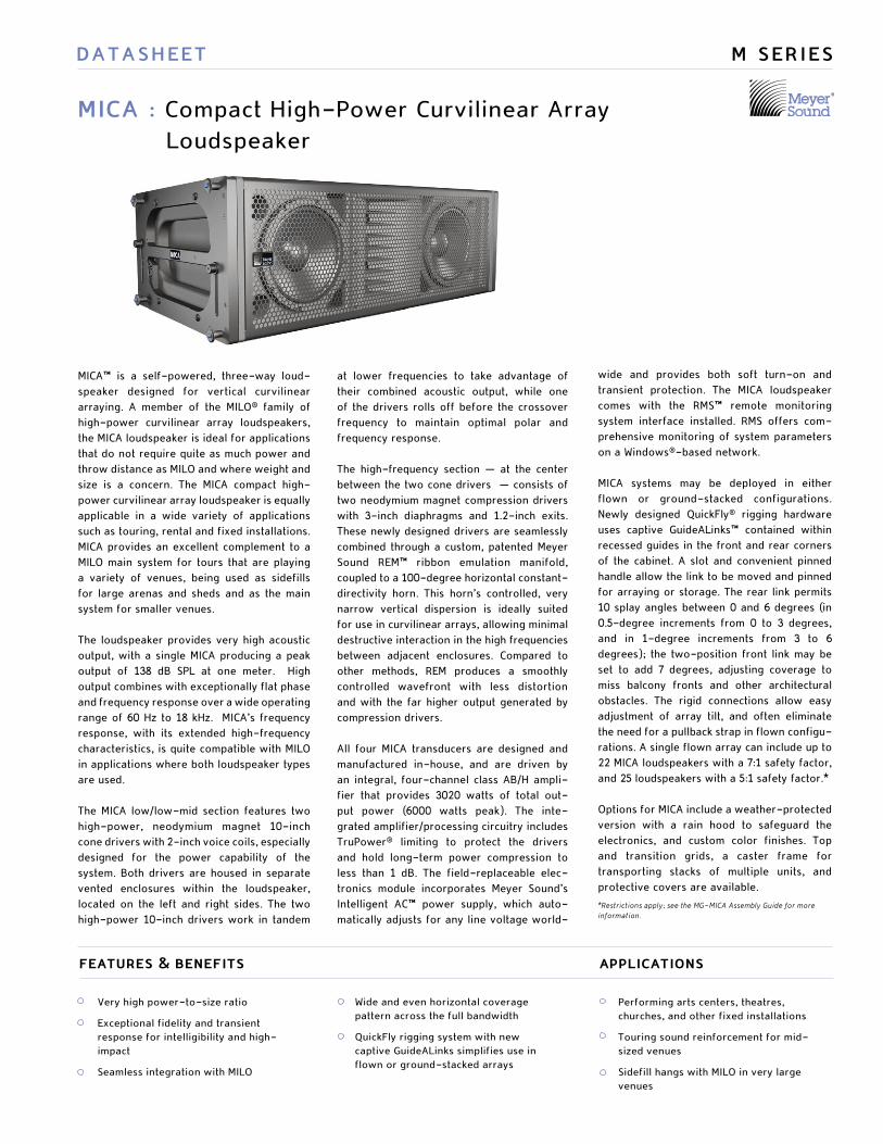
MICA™ is a self-powered, three-way loud-speaker designed for vertical curvilinear arraying. A member of the MILO® family of high-power curvilinear array loudspeakers, the MICA loudspeaker is ideal for applications that do not require quite as much power and throw distance as MILO and where weight and size is a concern. The MICA compact high-power curvilinear array loudspeaker is equally applicable in a wide variety of applications such as touring, rental and fixed installations. MICA provides an excellent complement to a MILO main system for tours that are playing a variety of venues, being used as sidefills for large arenas and sheds and as the main system for smaller venues.
The loudspeaker provides very high acoustic output, with a single MICA producing a peak output of 138 dB SPL at one meter. High output combines with exceptionally flat phase and frequency response over a wide operating range of 60 Hz to 18 kHz. MICA’s frequency response, with its extended high-frequency characteristics, is quite compatible with MILO in applications where both loudspeaker types are used.
The MICA low/low-mid section features two high-power, neodymium magnet 10-inch cone drivers with 2-inch voice coils, especially designed for the power capability of the system. Both drivers are housed in separate vented enclosures within the loudspeaker, located on the left and right sides. The two high-power 10-inch drivers work in tandem
MICA : Compact High-Power Curvilinear Array Loudspeaker
DATASHEET
at lower frequencies to take advantage of their combined acoustic output, while one of the drivers rolls off before the crossover frequency to maintain optimal polar and frequency response.
The high-frequency section — at the center between the two cone drivers — consists of two neodymium magnet compression drivers with 3-inch diaphragms and 1.2-inch exits. These newly designed drivers are seamlessly combined through a custom, patented Meyer Sound REM™ ribbon emulation manifold, coupled to a 100-degree horizontal constant-directivity horn. This horn’s controlled, very narrow vertical dispersion is ideally suited for use in curvilinear arrays, allowing minimal destructive interaction in the high frequencies between adjacent enclosures. Compared to other methods, REM produces a smoothly controlled wavefront with less distortion and with the far higher output generated by compression drivers.
All four MICA transducers are designed and manufactured in-house, and are driven by an integral, four-channel class AB/H ampli-fier that provides 3020 watts of total out-put power (6000 watts peak). The inte-grated amplifier/processing circuitry includes TruPower® limiting to protect the drivers and hold long-term power compression to less than 1 dB. The field-replaceable elec-tronics module incorporates Meyer Sound’s Intelligent AC™ power supply, which auto-matically adjusts for any line voltage world-
M SERIES
wide and provides both soft turn-on and transient protection. The MICA loudspeaker comes with the RMS™ remote monitoring system interface installed. RMS offers com-prehensive monitoring of system parameters on a Windows®-based network.
MICA systems may be deployed in either flown or ground-stacked configurations. Newly designed QuickFly® rigging hardware uses captive GuideALinks™ contained within recessed guides in the front and rear corners of the cabinet. A slot and convenient pinned handle allow the link to be moved and pinned for arraying or storage. The rear link permits 10 splay angles between 0 and 6 degrees (in 0.5-degree increments from 0 to 3 degrees, and in 1-degree increments from 3 to 6 degrees); the two-position front link may be set to add 7 degrees, adjusting coverage to miss balcony fronts and other architectural obstacles. The rigid connections allow easy adjustment of array tilt, and often eliminate the need for a pullback strap in flown configu-rations. A single flown array can include up to 22 MICA loudspeakers with a 7:1 safety factor, and 25 loudspeakers with a 5:1 safety factor.*
Options for MICA include a weather-protected version with a rain hood to safeguard the electronics, and custom color finishes. Top and transition grids, a caster frame for transporting stacks of multiple units, and protective covers are available.
*Restrictions apply; see the MG-MICA Assembly Guide for more information.
applicationsfeatures & benefits
Performing arts centers, theatres, churches, and other fixed installations
Touring sound reinforcement for mid-sized venues
Sidefill hangs with MILO in very large venues
Very high power-to-size ratio
Exceptional fidelity and transient response for intelligibility and high-impact
Seamless integration with MILO
Wide and even horizontal coverage pattern across the full bandwidth
QuickFly rigging system with new captive GuideALinks simplifies use in flown or ground-stacked arrays

Architect Specifications
About the Vertical Directivity Plots
The color images accompanying the upper diagram on the facing page are sound
intensity plots made using the Meyer Sound MAPP Online® acoustical prediction
program, a unique and highly accurate visualization tool for professional sound
system designers.
Using an Internet-connected personal computer, the designer
specifies Meyer Sound loudspeaker models, their locations,
how they are aimed and, optionally, the locations and
composition of walls. This information travels over the Internet
to a powerful server computer at Meyer Sound headquarters
in Berkeley, California. Running a sophisticated algorithm
and using highly accurate measured data that describe each
loudspeaker’s directional characteristics, the server predicts
the sound field that the loudspeakers will produce, forms
a color representation, and sends the result back for the
designer’s computer to display.
In these sound field plots, the color spectrum is used to represent
levels of sound intensity, with red being the loudest and blue
being the softest, as shown in the scale to the immediate right.
These examples illustrate coverage characteristics for an array
whose splay angles have been tailored to the actual venue; a
section view of the venue has been superimposed on the MAPP
Online plots.
The loudspeaker shall be a self-powered, full-range unit for deployment in line array systems. The low/low-mid frequency transducers shall consist of two 10-inch cone drivers, rated to handle 1200 watts AES* (1800 watts peak). The high-frequency transducers shall consist of two 3-inch diaphragm, 1.2-inch exit compression drivers, rated to handle 360 watts AES* (720 watts peak) coupled via a custom manifold to a 100-degree horizontal constant-directivity horn.
The loudspeaker shall incorporate internal processing and a four-channel amplifier. Processing functions shall include equalization, phase correction, driver protection and signal division for the two frequency sections. The crossover point shall be 1000 Hz. An additional low-frequency crossover shall cause the two low/low-mid frequency transducers to work in combination between 60 Hz and 320 Hz, with only one working up to the crossover frequency to maintain optimal polar characteristics.
Each amplifier channel shall be class AB/H with com-plementary MOSFET output stages. Burst capability shall be 3020 watts total (6000 watts peak) with two channels at 950 watts into a nominal 4-ohm load for the low and low-mid drivers and two channels at 560 watts into a nominal 8-ohm load for the high-frequency drivers. Distortion (THD, IM, TIM) shall not exceed 0.02%. Protection circuits shall include TruPower limiting. The audio input shall be electroni-cally balanced with a 10 kOhm impedance and accept a nominal 0 dBV (1 V rms, 1.4 V pk) signal (+20 dBV to produce maximum SPL). Connectors shall be XLR (A-3) type male and female. RF filtering shall be provided. CMRR shall be greater than 50 dB (typically 80 dB, 50 Hz – 500 Hz).
Performance specifications for a typical production unit shall be as follows, measured at 1/3-octave resolution: Operating frequency range shall be 60 Hz to 18 kHz. Phase response shall be ±30° from 1 kHz to 16 kHz. Maximum peak SPL shall be 138 dB at 1 meter. Beamwidth shall be 100 degrees horizontal. Vertical coverage in multi-cabinet arrays shall be dependent on system configuration.
The internal power supply shall perform automatic voltage selection, EMI filtering, soft current turn-on and surge suppression. Powering requirements shall be nominal 100, 110, or 230 V AC line current at 50 Hz or 60 Hz. UL and CE operating voltage range shall be 100 to 230 V AC. Maximum peak current draw during burst shall be 8.7 A at 115 V AC and 4.3 A at 230 V AC. Current inrush during soft turn-on shall not exceed 11 A at 115 V AC. AC power connectors shall be lock-ing NEMA L6-20, IEC 309 male, PowerCon or VEAM all-in-one.
The loudspeaker system shall incorporate the elec-tronics module for Meyer Sound’s RMS remote moni-toring system.
All loudspeaker components shall be mounted in an enclosure constructed of premium birch plywood with a hard and damage-resistant black textured finish. The front protective grille shall be powder-coated, hex-stamped steel. To build flown or ground-stacked loudspeaker arrays, linking to the grid and between cabinets shall be accomplished with QuickFly rigging hardware using captive GuideALinks allowing 10 rear splay angles between 0 and 6 degrees, with a two-position front link settable at 0 or 7 degrees.
Dimensions shall be 41.40" wide by 13.37" high (cabinet front) by 17.78" deep (1052 mm x 340 mm x 452 mm). Weight shall be 150 lbs (68.04 kg).
The loudspeaker shall be the Meyer Sound MICA.
*Both transducers driven continuously for two hours with band-limited noise signal having a 6 dB peak-average ratio.
41.40" w x 13.37" h x 17.78" d
(1052 mm x 340 mm x 452 mm)
150 lbs (68.04 kg)
Premium birch plywood
Black textured
Powder-coated hex-stamped steel
MRF-MICA rigging frame, with captive
GuideALink connectors and quick-
release pins
Dimensions
Weight
Enclosure
Finish
Protective Grille
Rigging
41.40 [1052mm]
43.88 [1115mm]
13.37 [340mm] 11.58
[294mm]
9.00 [229mm]
6.40 [163mm]
7.30 [185mm]
8.44 [214mm]
11.38 [289mm]
22.80 [579mm]
17.78 [452mm]1
Case
220KESD
10KBalanced
LoopInput
Auto-Voltage Select95-125V~ 208-235V~50-60Hz 50-60Hz2000W RMS MAX 2000W RMS MAX
Operational Voltage Range:Turn on 85V~ Turn off 134V~Turn on 165V~ Turn off 264V~
ytivitcAteseR
kniWecivreS
Network
Remote Monitor System
THIS PRODUCT MUST BE GROUNDEDWARNINGS:
TruPower ™
MICA
High Ch Limit
Low Ch Limit
Active
Ω
3 -2 +
Earth/Chassis
Ω
PUSH
RE
- CIRK- IT
ATENCIÓN: ACCESO INTERNO SOLO AUTORIZADO A PERSONAL TÉCNICO CALIFICADO
ACHTUNG: GEHÄUSE NICHT ÖFFNEN WARTUNG UND REPARATUR NUR DURCH ELEKTROFACHKRÄFTE
ATTENTION: ENTRETIEN ET REPARATIONS INTERNES NE SONT AUTORISEES QU'AU PERSONNEL TECHNIQUE QUALIFIÉ
UK WARNING: THIS APPARATUS MUST BE EARTHED. NO OPERATOR SERVICEABLE PARTS INSIDE. REFER SERVICING TO QUALIFIED PERSONNEL:
This surface may reach high temperatures while in use.To ensure proper operation, allow at least 6 inches clearance from this surface and adequate ventilation.No operator serviceable parts inside.Refer servicing to qualified personnel.To reduce the risk of fire or electric shock do not expose this appliance to rain or moisture.
Meyer Sound, Berkeley, CA, USA
PUSH
RE
- CIRK- IT
2 23 1 1

Signal Flow for a Typical Reinforcement System
MICA Vertical Splay and Coverage
MICA loudspeakers permit versatile arrays and are compatible with other Meyer Sound reinforcement loudspeakers, giving sound designers maximum freedom to customize systems for their needs. This block diagram illustrates the signal flow for a typical sound reinforcement system using 12 MICA cabinets per side for the main arrays.
These illustrations show how the splay between adjacent cabinets in a MICA array may be adjusted to tailor coverage for a specific venue. The MAPP Online plots on the right illustrate the vertical directivity characteristics of the array on the left, with a section view of an example venue superimposed.
2 kHz
4 kHz
1 kHz
500 Hz
250 Hz
8 kHz
125 Hz
Digital Delay
2 In x 6 OutDigital Delay/EQ
LD-3Channel A
IN SUB OUT
CH 1 OUT
CH 2 OUT
CH 3 OUT
Channel BIN SUB OUT
CH 1 OUT
CH 2 OUT
CH 3 OUT
Channel AINSERTS SENDSIN SUB OUT
Full RangeIN CH 1 OUT
Post ArrayIN CH 2 OUT
Post ArrayIN CH 3 Post HPF
Channel BINSERTS SENDSIN SUB OUT
Full RangeIN CH 1 OUT
Post ArrayIN CH 2 OUT
Post ArrayIN CH 3 Post HPF
MainLeft
MainRight
OptionalSubwooferMono
(6) 700-HP (6) 700-HP
(12) MICA (12) MICA

MICA Specifications
1. Recommended maximum operating frequency range. Response depends on loading conditions and room acoustics.
2. Free field, measured with 1/3-octave frequency resolution at 4 meters.
3. Measured with music referred to 1 meter.
4. At these frequencies, the transducers produce equal sound pressure levels.
5. Power handling is measured under AES standard conditions: both transducers driven continuously for two hours with band-limited noise signal having a 6 dB peak-average ratio.
6. Peak power handling is measured with both transducers driven for 100 milliseconds with pink noise signal having a 12 dB peak-average ratio.
7. The two drivers are coupled to a 100-degree horizontal constant-directivity horn through a propri-etary acoustical combining manifold (REM).
8. Amplifier wattage rating based on the maximum unclipped burst sine-wave rms voltage that the amplifier will produce for at least 0.5 seconds into the nominal load impedance: 62 V rms low channels and 67 V rms high channels.
9. Peak power based on the maximum unclipped peak voltage that the amplifier will produce for at least 100 milliseconds into the nominal load impedance: 87 V pk low channels and 95 V pk high channels.
10. AC power cabling must be of suf-ficient gauge so that under burst current rms conditions, cable trans-mission losses do not drop voltage below specified operating range at the speaker.
meyer sound laboratories inc.2832 San Pablo AvenueBerkeley, CA 94702
T: +1 510 486.1166F: +1 510 486.8356
MICA — 04.147.004.01 A
Copyright © 2005 Meyer Sound Laboratories Inc.
Operating Frequency Range1
Free Field Frequency Response2
Phase Response
Maximum Peak SPL3
Dynamic Range
Horizontal Coverage
Vertical Coverage
Low/Low-Mid Frequency
High Frequency7
Type
Maximum Common Mode Range
Connectors
Input Impedance
Wiring
DC Blocking
CMRR
RF Filter
TIM Filter
Nominal Input Sensitivity
Input Level
Type
Output Power8
Total Output9
THD, IM, TIM
Load Capacity
Cooling
Connector
Automatic Voltage Selection
Safety Agency Rated Operating Range
Turn-on and Turn-off Points
Current Draw: Idle Current
Max Long-Term Continuous Current (>10 sec)
Burst Current (<1 sec)10
Ultimate Short-Term Peak Current Draw
Inrush Current
60 Hz - 18 kHz
75 Hz - 17 kHz ±4 dB
1 kHz - 16 kHz ±30°
138 dB
>110 dB
100°
Varies, depending on array length and configuration
1000 Hz
Two high-power 10" cone drivers with neodymium magnets
Nominal impedance: 4 ΩVoice coil size: 2"
Power handling capability: 1200 W (AES)5; 1800 W peak6
Two 3" compression drivers
Nominal impedance: 8 ΩVoice coil size: 3"
Diaphragm size: 3"
Exit size: 1.2"
Power handling capability: 360 W (AES)5; 720 W peak6
Differential, electronically balanced
±15 V DC, clamped to earth for voltage transient protection
Female XLR input with male XLR loop output or VEAMall-in-one
connector (integrates AC, audio and network)
10 kΩ differential between pins 2 and 3
Pin 1: Chassis/earth through 220 kΩ, 1000 pF, 15 V clamp network
to provide virtual ground lift at audiofrequencies
Pin 2: Signal +
Pin 3: Signal -
Case: Earth ground and chassis
None on output, DC blocked through signal processing
>50 dB, typically 80 dB (50 Hz–500 Hz)
Common mode: 425 kHz
Differential mode: 142 kHz
Integral to signal processing (<80 kHz)
0 dBV (1 V rms, 1.4 V pk) continuous is typically the onset of
limiting for noise and music
Audio source must be capable of producing a minimum of +20 dBV
(10 V rms, 14 V pk) into 600 Ω inorder to produce maximum peak
SPL over the operating bandwidth of the loudspeaker
Four-channel complementary MOSFET output stages (class AB/H)
3020 W (four channels; 2 x 950 W, 2 x 560 W)
6000 W peak
<.02%
4 Ω low and mid channels; 8 Ω high channels
Forced air cooling, four fans (two ultrahigh-speed reserve fans)
250 V AC NEMA L6-20 twistlock, IEC-309 male, PowerCon, or VEAM
Automatic, two ranges, each with high-low voltage tap
(uninterrupted)
95 V AC - 125 V AC; 208 V AC - 235 V AC, 50/60 Hz
85 V AC - 134 V AC; 165 V AC - 264 V AC
1.1 A rms (115 V AC); 0.55 A rms (230 V AC); 1.3 A rms (100 V AC)
5.4 A rms (115 V AC); 2.7 A rms (230 V AC); 6.2 A rms (100 V AC)
8.7 A rms (115 V AC), 4.3 A rms (230 V AC), 10.0 A rms (100 V AC)
24.6 A rms (115 V AC), 12.3 A rms (230 V AC), 28.3 A rms (100 V AC)
11 A rms (115 and 100 V AC), 15 A rms (230 V AC)
Equipped with two-conductor twisted-pair network, reporting
all operating parameters of amplifiers to system operator’s host
computer
Notes:Acoustical
Coverage
Crossover4
Transducers
Audio Input
Amplifier
AC Power
RMS Network
European Office:Meyer Sound Lab. GmbHCarl Zeiss Strasse 1356751 Polch, Germany
Made by Meyer Sound LaboratoriesBerkeley, California USA