Embed Size (px)
Citation preview
A L F A L A V A L S E P A R A T I O N
MIB 303S-13/33
Separator Manual
Product No. 881176-06-01
Book No. 1271024-02 V1

Alfa Laval Separation ABSeparator Manuals, dept. SKLS-147 80 Tumba, Sweden
Telephone: +46 8 53 06 50 00Telefax: +46 8 53 06 50 29
Printed in Sweden, 97-09
© Alfa Laval Separation AB 1997
This publication or any part thereof may not be reproduced or transmitted by any process or means without prior written permission of Alfa Laval Separation AB.

Contents
1 Safety Instructions 7
2 Separator Basics 11
2.1 Basic principles of separation 13
2.2 Application 13
2.3 Description of main parts 14
2.4 Working principle (purifier) 16
2.5 Conversion kit 19
2.6 Working principle (clarifier) 20
3 Operating Instructions 23
3.1 Operating routine 25
3.2 Before start 25
3.3 Start 26
3.4 Operation 26
3.5 Stop 26
3.6 Automatic stop 27
4 Trouble shooting 29
4.1 The separator does not start 31
4.2 Low outlet flow (low outlet pressure) 31
4.3 No outlet flow (no outlet pressure) 32
4.4 The separator stops 32
4.5 The separator vibrates 33
4.6 Insufficient separation 33
4.7 Noise 34
3

5 Maintenance 35
5.1 Periodic cleaning 37
5.2 Preventive maintenance every year 38
5.3 Preventive maintenance every two years 38
6 Dismantling and assembly 41
6.1 Instructions 43
6.2 Operation chart selection 44
7 Technical data 63
7.1 Technical data 65
7.2 Basic size drawing 67
7.3 Connection diagram 71
4

ls and observe the ion, operation, .
ions can result in
clear only foreseeable conditions ings are given, therefore, for
ended usage of the machine and its
Study instruction manuawarnings before installatservice and maintenance
Not following the instructserious accidents.
In order to make the informationhave been considered. No warnsituations arising from the uninttools.
5

6
1 Safety Instructions
G00
104
11
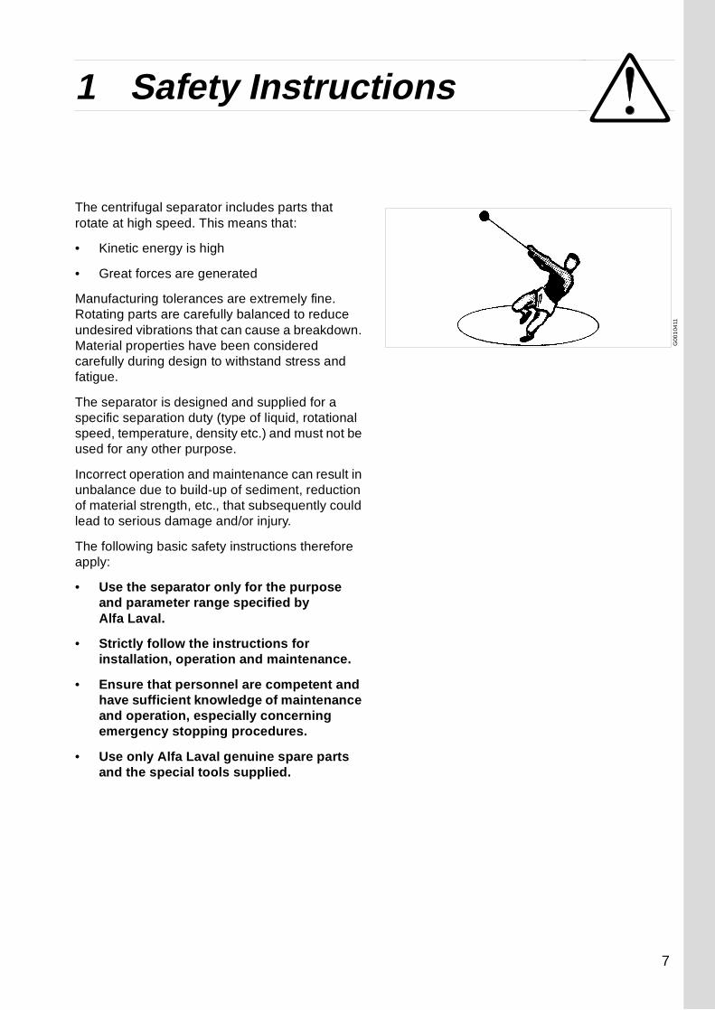
The centrifugal separator includes parts that rotate at high speed. This means that:
• Kinetic energy is high
• Great forces are generated
Manufacturing tolerances are extremely fine. Rotating parts are carefully balanced to reduce undesired vibrations that can cause a breakdown. Material properties have been considered carefully during design to withstand stress and fatigue.
The separator is designed and supplied for a specific separation duty (type of liquid, rotational speed, temperature, density etc.) and must not be used for any other purpose.
Incorrect operation and maintenance can result in unbalance due to build-up of sediment, reduction of material strength, etc., that subsequently could lead to serious damage and/or injury.
The following basic safety instructions therefore apply:
• Use the separator only for the purpose and parameter range specified by Alfa Laval.
• Strictly follow the instructions for installation, operation and maintenance.
• Ensure that personnel are competent and have sufficient knowledge of maintenance and operation, especially concerning emergency stopping procedures.
• Use only Alfa Laval genuine spare parts and the special tools supplied.
7

1 Safety Instructions
DANGER
Disintegration hazards
• Use the separator only for the purpose and parameter range specified by Alfa Laval.
• If excessive vibrations occur, keep liquid feed on and stop separator.
• Welding or heating of parts that rotate can seriously affect material strength.
• Inspect regularly for corrosion and erosion damage. Inspect frequently if process liquid is corrosive or erosive.
Entrapment hazards
• Make sure that rotating parts have come to a complete standstill before starting any dismantling work.
• To avoid accidental start, switch off and lock power supply before starting any dismantling work.
• Assemble the machine completely before start. All covers and guards must be in place.
Electrical hazards
• Follow local regulations for electrical installation and earthing (grounding).
8
1 Safety Instructions
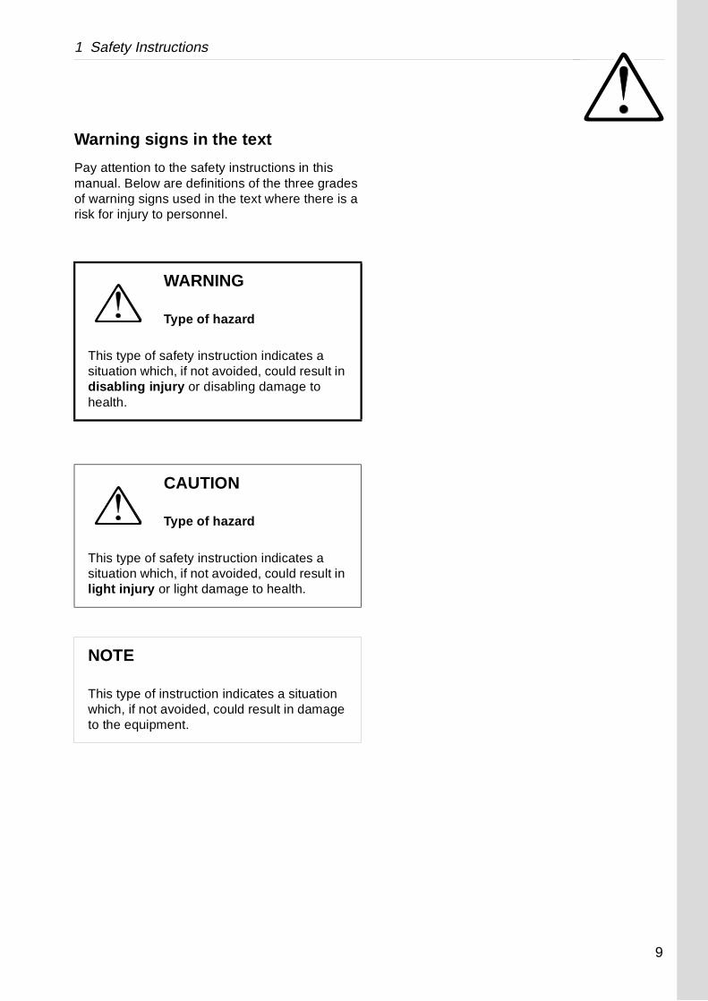
Warning signs in the text
Pay attention to the safety instructions in this manual. Below are definitions of the three grades of warning signs used in the text where there is a risk for injury to personnel.
WARNING
Type of hazard
This type of safety instruction indicates a situation which, if not avoided, could result in disabling injury or disabling damage to health.
CAUTION
Type of hazard
This type of safety instruction indicates a situation which, if not avoided, could result in light injury or light damage to health.
NOTE
This type of instruction indicates a situation which, if not avoided, could result in damage to the equipment.
9

1 Safety Instructions
/60 Hz 24V DC
30A
S0
068
7B1
Warning label
S00
6141
1
Warning label
Warning label placed on the separator hood.
Interpretation:
Stop! Read the instruction manuals before installation, operation and maintenance.
Failure to strictly follow instructions can lead to fatal injury.
Machine plate
Plate placed on the separator base.
Text on label:
Separator type MIB 303S-13/33
Product number 881176-06-01
Speed max. 7 500 r/min
Rotation ----->
Supply voltage 230V ~50/60 Hz 110V ~50
Current max. 4 A 8A
10

2 Separator Basics
Contents
2.1 Basic principles of separation 13
2.2 Application 13
2.3 Description of main parts 14
2.4 Working principle (purifier) 16
2.5 Conversion kit 19
2.6 Working principle (clarifier) 20
11

12

2 Separator Basics 2.1 Basic principles of separation
cosity at +40 °C
5 - 6 cSt
to 14 cSt
to 150 cSt
ax. 50 cS
2.1 Basic principles of separation
2.2 ApplicationThe use of the separator is restricted to removal of water and solids from gasoil, mineral oil or marine diesel oil.
Marine diesel oils should be preheated to +70 °C which is the maximum permissible separation temperature
Following are examples of oils to be treated:
Oil type Density at +15 °C Vis
Gas oil 810 - 860 kg/m3 1,
Marine diesel oil 850 - 920 kg/m3 up
Lube oil Max. 920 kg/m3 up
Mineral oil M
WARNING
Do not use the MIB 303S-13/33 separator for separating any oils or liquids other than those specified above.
13

2.3 Description of main parts 2 Separator Basics
B
H
G
E
F
A D
C
G0
4505
11
Fig. 1 Separator
A. Oil inletB. Water collecting channelC. Water outletD. Oil outletE. BowlF. Rubber cushionsG. MotorH. Frequency converter
More details shown in ‘‘ Fig. 2 Separator main parts” on page 15
2.3 Description of main parts
A general view of the MIB 303S-13/33 separator is shown in fig 1.
The oil is fed to the oil inlet (A) and down to the rotating bowl (E) where separation takes place. Separated water runs down the water collecting channel (B) to the water outlet (C), while the cleaned oil leaves the separator at (D).
The bowl and motor (G) are suspended on rubber cushions(F).
The frequency converter (H) for the motor is mounted at the bottom of the separator.
14
2 Separator Basics 2.3 Description of main parts
G0
4062
21
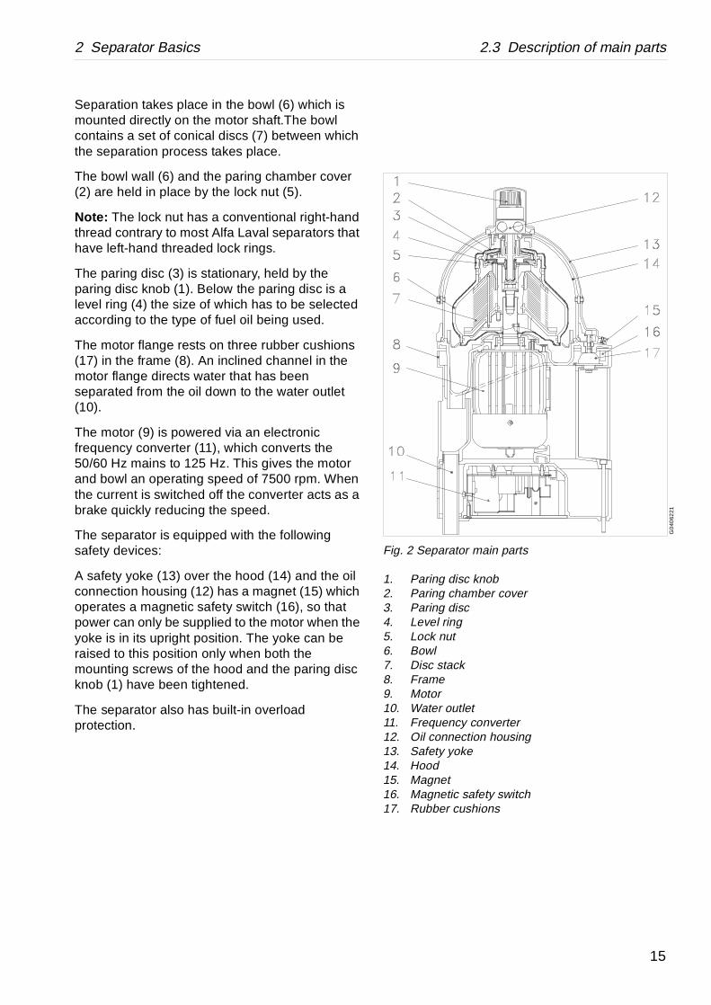
Fig. 2 Separator main parts
1. Paring disc knob2. Paring chamber cover3. Paring disc4. Level ring5. Lock nut6. Bowl7. Disc stack8. Frame9. Motor10. Water outlet11. Frequency converter12. Oil connection housing13. Safety yoke14. Hood15. Magnet16. Magnetic safety switch17. Rubber cushions
Separation takes place in the bowl (6) which is mounted directly on the motor shaft.The bowl contains a set of conical discs (7) between which the separation process takes place.
The bowl wall (6) and the paring chamber cover (2) are held in place by the lock nut (5).
Note: The lock nut has a conventional right-hand thread contrary to most Alfa Laval separators that have left-hand threaded lock rings.
The paring disc (3) is stationary, held by the paring disc knob (1). Below the paring disc is a level ring (4) the size of which has to be selected according to the type of fuel oil being used.
The motor flange rests on three rubber cushions (17) in the frame (8). An inclined channel in the motor flange directs water that has been separated from the oil down to the water outlet (10).
The motor (9) is powered via an electronic frequency converter (11), which converts the 50/60 Hz mains to 125 Hz. This gives the motor and bowl an operating speed of 7500 rpm. When the current is switched off the converter acts as a brake quickly reducing the speed.
The separator is equipped with the following safety devices:
A safety yoke (13) over the hood (14) and the oil connection housing (12) has a magnet (15) which operates a magnetic safety switch (16), so that power can only be supplied to the motor when the yoke is in its upright position. The yoke can be raised to this position only when both the mounting screws of the hood and the paring disc knob (1) have been tightened.
The separator also has built-in overload protection.
15

2.4 Working principle (purifier) 2 Separator Basics
Fig. 3 Process principle (opposite page)
1. Oil inlet2. Bowl3. Water seal4. Water outlet radius5. Bowl discs6. Oil outlet radius
2.4 Working principle (purifier)
Uncleaned oil continuously enters at (1), in fig 3, and flows into the bowl (2). The bowl rotates at high speed generating powerful centrifugal forces. As the oil rotates with the bowl, the heavier contents of the oil, such as solid particles and water, move towards the periphery of the bowl. The particles are deposited on the bowl wall, while water collects in the water seal space (3) and drains at (4) into the water channel below the bowl.
The discs (5) in the bowl make the separation process very efficient and the cleaned oil leaves the bowl through the paring chamber at a constant pressure. The paring chamber which contains the stationary paring disc is not shown in this illustration.
The water seal is very important as it prevents oil from leaving the bowl through the water outlet. To establish the necessary water seal, a small amount of water has to be fed into the bowl before the uncleaned oil is fed to the bowl. The heavier water prevents the oil from escaping the wrong way.
More information about the theory of centrifugal separation can be obtained from your local Alfa Laval representative.
16

2 Separator Basics 2.4 Working principle (purifier)
Detta blad utbytes mot färgbild:
G-04490-1-1
17

2.4 Working principle (purifier) 2 Separator Basics
18

2 Separator Basics 2.5 Conversion kit
2.5 Conversion kitIf the liquid to clean only contains smaller amounts of water and solids, the purifier bowl can be converted to a clarifier, using the optional conversion kit to replace the purifier parts in bowl see ‘‘6.2 Operation chart selection” on page 44 instruction C1.
A brief explanation of the clarifying mode is given on page 20.
19

2.6 Working principle (clarifier) 2 Separator Basics
Fig. 4 Process principle (opposite page)
1. Oil inlet2. Bowl3. Collected solid particles4. Bowl discs5. Oil outlet
2.6 Working principle (clarifier)
Uncleaned oil continuously enters at (1), in fig 4, and flows into the bowl (2). The bowl rotates at high speed generating powerful centrifugal forces. As the oil rotates with the bowl, the heavier contents of the oil, such as solid particles and water, move towards the periphery of the bowl. The particles are deposited on the bowl wall, while water collects in the sludge and water space (3) and drains into the channel below the bowl, when the rotation is stopped.
The discs (4) in the bowl make the separation process very efficient and the cleaned oil (5) leaves the bowl through the paring chamber at a constant pressure. The paring chamber which contains the stationary paring disc is not shown in this illustration.
More information about the theory of centrifugal separation can be obtained from your local Alfa Laval representative.
20

2 Separator Basics 2.6 Working principle (clarifier)
Detta blad utbytes mot färgbild:
G-05192-1-1
21

2.6 Working principle (clarifier) 2 Separator Basics
22

3 Operating Instructions
Contents
3.1 Operating routine 25
3.2 Before start 25
3.3 Start 26
3.4 Operation 26
3.5 Stop 26
3.6 Automatic stop 27
Before start
Start and run-up
Running
Stop procedure
The operating procedure:
23

24

3 Operating Instructions 3.1 Operating routine
3.1 Operating routine
These operating instructions describe routine pro-cedures to follow before and during the start, running and stopping sequences of the separator.
3.2 Before start• Make sure that the separator is installed
according to the instructions given in chapter ‘‘8.2 Installation” on page 78.
• Make sure that the correct level ring is installed:
- For cleaning gas oil only, install the white level ring which has a 43 mm diameter hole.
- For cleaning marine diesel oil and lube oil, install the black level ring which has a 50 mm diameter hole.
- For alternating between marine diesel oil and gas oil, install the black level ring which has a 50 mm diameter hole.
WARNING
The separator is supplied with a safety yoke and a magnetic safety switch. Modifications to the machine which put the safety devices out of operation can lead to serious injury or damage.
NOTE
If there is a System Manual, always follow the operating instructions given therein. If there is no System Manual the instructions below are to be followed.
25

3.3 Start 3 Operating Instructions
• Make sure that the hood screws and the paring disc knob are firmly tightened and that the safety yoke is in its closed (vertical) position.
3.3 Start1. Make sure that the outlet valve is open.
2. Start the separator. Note! hold the button depressed till the machine is running.
3. After 20 seconds, when the separator has gained full speed, feed at least one litre of water into the oil inlet line. This will create the water seal.
4. Turn on the oil feed to the separator.
5. Regulate the counter-pressure in the oil outlet line to 40-60 kPa.
6. After 1 minute, check that oil is not discharging from the separator through the water outlet (at the bottom). If oil escapes through the water outlet, stop the oil feed and follow the instructions given in ‘‘4.3 No outlet flow (no outlet pressure)” on page 32.
3.4 OperationCheck the separator for correct operation. This is especially important the first few times the separator is run after installation or after any dismantling and assembly has been carried out.
3.5 Stop1. Turn off the oil feed.
2. Stop the separator.
The bowl will almost have stopped rotating after about 1 minute. Approximately 1 litre of oil and water will flow out of the water outlet at the bottom of the separator. This is the normal draining of the bowl as it stops.
26

3 Operating Instructions 3.6 Automatic stop
3. Make sure that the valves are closed on both the feed and outlet sides of the separator. If this is not done oil may siphon off through the separator and the water collecting vessel will overflow.
3.6 Automatic stopThe separator is automatically stopped by the built-in electronic safety devices if one of the following situations should occur:
− too high current due to overload of the separator motor
− too high temperature in the frequency converter
− wrong frequency from converter.
Auxiliary safety devices, that also stop the separator: See ‘‘7.3 Connection diagram” on page 71,72 and 73
If the separator does not start or if it stops during operation, follow the instructions given in ‘‘4.1 The separator does not start” on page 31.
CAUTION
If the separator stops, the oil feed must be stopped immediately or there will be serious oil overflow.
27

3.6 Automatic stop 3 Operating Instructions
28

4 Trouble shooting
Contents
4.1 The separator does not start 31
4.2 Low outlet flow (low outlet pressure) 31
4.3 No outlet flow (no outlet pressure) 32
4.4 The separator stops 32
4.5 The separator vibrates 33
4.6 Insufficient separation 33
4.7 Noise 34
29

30

4 Trouble shooting 4.1 The separator does not start
yoke correctly.
ains switch, fuses and supply line.
hat the switch opens and closes when the safety ed up and down. Measure across terminal points on the frequency converter board. Replace the lty.
hat the bowl and motor shaft can rotate freely by ottom end of the motor shaft with a suitable tool.
e height of the paring disc as shown in eight A should be m and can be the number of 1-3 pcs) under the n housing.
a Laval representative test the converter.
line.
knob.
heck especially that no O-rings are missing, incorrectly installed. Assemble correctly.
G04
1783
1
4.1 The separator does not start
4.2 Low outlet flow (low outlet pressure)
Possible cause Action
Safety yoke is not in the correct position.
Position the
No power supplied to the separator. Check the m
Defective magnetic safety switch. Make sure tyoke is movNo. 5 and 6switch if fau
Incorrect assembly after cleaning. Make sure tturning the b
Incorrect height adjustment of paring disc after major overhaul.
CHECK: Thadjustment is measuredfigure. The h48,5 ±0,5 madjusted bywashers B (oil connectio
Defective frequency converter. Have an Alf
Possible cause Action
Low feed flow. Check feed
Paring disc knob is not completely tightened, causing leakage.
Tighten the
Leakage caused by incorrect assembly.
Dismantle. Cdefective or
31

4.3 No outlet flow (no outlet pressure) 4 Trouble shooting
line.
s if there is no water seal. Either no water was rt-up or the water seal has broken during dd 1 litre of water to create a new water seal.
epeats itself so that oil again discharges through tlet the density of the oil is too high. Stop the d fit the black level ring instead of the white one.
evel ring is already installed, this oil cannot be e separator because the density of the oil is too
heck especially that no O-rings are missing, incorrectly installed. Assemble correctly.
he yoke. Running position = vertical.
owl assembly.
a Laval representative test the converter.
4.3 No outlet flow (no outlet pressure)
4.4 The separator stops
Possible cause Action
No feed. Check feed
The feed functions properly but oil discharges through the water outle (purifier only).
This happenadded at staoperation. A
If this fault rthe water ouseparator anIf the black lcleaned in thhigh.
Leakage caused by incorrect assembly.
Dismantle. Cdefective or
Possible cause Action
The safety yoke has been moved out of its position.
Reposition t
Overload due to incorrect assembly. Check the b
Defective frequency converter. Have an Alf
32

4 Trouble shooting 4.5 The separator vibrates
owl carefully.
ntre screw.
ssemble ess the paring ver down firmly, erwise the lock e installed
dampers.
rings.
owl. Shorten the cleaning interval.
black level ring with the smaller (white) level ring.
f the feed rate improves the separation result.
G0
5008
11
4.5 The separator vibrates
4.6 Insufficient separation
Possible cause Action
Bowl out of balance due to:
− Insufficient or incorrect cleaning.
Clean the b
− Centre screw is missing. Install the ce
− Paring chamber cover and lock-nut are not correctly installed.
Dismantle. Acorrectly. Prchamber co(see fig.) othnut cannot bcorrectly.
Vibration dampers are worn. Fit three new
Motor bearings are damaged. Fit new bea
Possible cause Action
Insufficient cleaning. Clean the b
The black level ring is too large for present oil (purifier only).
Replace the
Oil feed rate is too high. Reduction o
33

4.7 Noise 4 Trouble shooting
nd assemble correctly.
rings.
pers
4.7 Noise
Possible cause Action
Incorrect assembly. Dismantle a
Bearings damaged. Fit new bea
Vibration dampers are worn Fit new dam
34

5 Maintenance
Contents
5.1 Periodic cleaning 37
5.1.1 Bowl cleaning 37
5.2 Preventive maintenance every year 38
5.3 Preventive maintenance every two years 38
5.3.1 Disc stack replacement 38
5.3.2 Vibration damper replacement 39
35

36

5 Maintenance 5.1 Periodic cleaning
5.1 Periodic cleaning
5.1.1 Bowl cleaning
The separator must be stopped at regular intervals and the bowl opened for removal of collected sludge. This is important for correct operation of the separator and achieving the desired result.
The length of the periods between cleaning depends on the feed rate of the oil and on the quantity of solid particles in the oil. During the initial period, open and inspect the bowl once every 24 hours to determine the necessary cleaning interval.
The bowl must be cleaned before the solids layer of the bowl has become thicker than 10 mm.
The cleaning procedure is shown in‘‘6.2 Operation chart selection” on page 44.
WARNING
Switch off the main power supply before dismantling for repair. Lock the mains switch in its OFF position.
WARNING
Never use cleaning agents with a pH below 6 or above 8 as they will damage the metal surfaces.
37

5.2 Preventive maintenance every year 5 Maintenance
5.2 Preventive maintenance every year
Replace the O-rings with the new ones supplied in the O-ring Service Kit. Their positions are shown in the Spare Parts List and the dismantling and assembly procedures are shown in the Dismantling and Assembly chapter.
Before fitting, lubricate the O-rings with the silicone grease supplied in the service kit.
5.3 Preventive maintenance every two years
5.3.1 Disc stack replacement
At separation temperature 60 °C and below, it isrecommended to fit a new stack every two years to ensure that the separation efficiency is maintained.
At separation temperature above 60 °C, it is recommended that the disc stack is replaced every year or at any sign of brittleness.
The replacement procedure is shown in the ‘‘6.2 Operation chart selection” on page 44.
The disc stack is available as a set.
38

5 Maintenance 5.3 Preventive maintenance every two years
5.3.2 Vibration damper replacement
Fit new vibration dampers every two years. Inspect the stop flanges of the dampers for possible damage and replace the stop flanges with new ones if necessary.
The replacement procedure is shown in the Dismantling and Assembly chapter ‘‘6.2 Operation chart selection” on page 44.
The vibration dampers are available as a set (see Spare Parts Catalogue).
WARNING
The separator must not be operated unless the stop flanges for the vibration dampers are correctly installed.
39

5.3 Preventive maintenance every two years 5 Maintenance
40

6 Dismantling and assembly
Contents
6.1 Instructions 43
6.2 Operation chart selection 44
41

6 Dismantling and assembly
42

6 Dismantling and assembly 6.1 Instructions
Press or move in the direc-tion of arrow
Clean
Check, make sure
Safety
S-00438-1-1 S-00443-1-1
S-00440-1-1 S-00003-1-1
G04
502
21
6.1 InstructionsThe illustrations on the following pages describe step by step how to dismantle, clean, replace and assemble the various parts of the separator.
The illustrations have only symbols to indicate the action required. The key to the symbols is given below.
A. Select the correct chart.
The green introductory illustration (1) indicates the part which will be dealt with in the chart (see the chart designation letter (2)) and ‘‘6.2 Operation chart selection” on page 44.
B. Collect the tools needed.
Tools required are marked in Yellow (3).
C. Follow the instructions in numerical order
The part concerned is marked in blue (4).The symbol indicates the action required (5).
RemoveScrew orturn clock-wise
Fit, insertScrew or turn counter-clockwise
S-00439-1-1S-00442-1-1
S-00444-1-1 S-00441-1-1
43

6.2 Operation chart selection 6 Dismantling and assembly
rations
G0
4800
31G
0480
141
G0
4801
31G
0480
231
G04
8033
1G
048
043
1G
048
0531
G04
8063
1
6.2 Operation chart selection
Operation Charts and illust
Bowl cleaning
O-rings and disc stackreplacement
Purifier
Clarifier
Bearing replacement
Connection housing dismantling and assembly
Frequency converter replacement
Level ringreplacement (purifier only)
Vibration damperreplacement
44

6 Dismantling and assembly 6.2 Operation chart selection
Detta blad utbytes mot färgbild:
G-04491-2-1
45

6.2 Operation chart selection 6 Dismantling and assembly
46

6 Dismantling and assembly 6.2 Operation chart selection
Detta blad utbytes mot färgbild:
G-04492-2-1
47

6.2 Operation chart selection 6 Dismantling and assembly
48

6 Dismantling and assembly 6.2 Operation chart selection
Detta blad utbytes mot färgbild:
G-04493-2-1
49

6.2 Operation chart selection 6 Dismantling and assembly
50

51
Detta blad utbytes mot färgbild:
G-05191-9-1

52

6 Dismantling and assembly 6.2 Operation chart selection
Detta blad utbytes mot färgbild:
G-04494-2-1
53

6.2 Operation chart selection 6 Dismantling and assembly
54

6 Dismantling and assembly 6.2 Operation chart selection
Detta blad utbytes mot färgbild:
G-04495-2-1
55

6.2 Operation chart selection 6 Dismantling and assembly
56

6 Dismantling and assembly 6.2 Operation chart selection
Detta blad utbytes mot färgbild:
G-04496-2-1
57

6.2 Operation chart selection 6 Dismantling and assembly
58

6 Dismantling and assembly 6.2 Operation chart selection
Detta blad utbytes mot färgbild:
G-04497-2-1
59

6.2 Operation chart selection 6 Dismantling and assembly
60

6 Dismantling and assembly 6.2 Operation chart selection
Detta blad utbytes mot färgbild:
G-04498-2-1
61

6.2 Operation chart selection 6 Dismantling and assembly
62

7 Technical data
Contents
7.1 Technical data 65
7.1.1 Type designation 65
7.1.2 Capacities 65
7.1.3 Electric motor drive 65
7.1.4 Lubrication 66
7.1.5 Operation conditions 66
7.1.6 Weight 66
7.1.7 Dimensions 66
7.1.8 Connections 66
7.1.9 Sound 66
7.1.10 Material 66
7.2 Basic size drawing 67
7.2.1 Connection list 68
7.2.2 Interface description 69
7.3 Connection diagram 71
7.3.1 230 V AC 71
7.3.2 110 V AC 72
7.3.3 24 V DC 73
63

64

7 Technical data 7.1 Technical data
e
ds
7.1 Technical dataAlfa Laval ref. 557925 , rev. 2
7.1.1 Type designation
MIB 303S-13/33
7.1.2 Capacities
7.1.3 Electric motor drive
The drive comprises a frequency converter and a motor. The motor is wired to suit the voltage and frequency delivered by the frequency converter.
The frequency converter brakes the bowl speed to below 1000 r/min within 25 seconds after switching off the current.
Hydraulic capacity 1 m3/h
Maximum density
− of sediment
− of feed
1600 kg/m3
1000 kg/m3
Feed temperature
− Minimum
− Maximum
+15 °C
+70 °C
Motor power 0,45 kW
Power consumption
− Idling
− At maximum capacity
0,2 kW
0,4 kW
Rated current− At 24 V DC− At 110 V AC− At 230 V AC
30 A8 A4 A
Speed 7500 r/min
Direction of rotation Counter-clockwis
Running up time 30 seconds
Stopping time 100 to 180 secon
65

7.1 Technical data 7 Technical data
7.2 Basic size drawing”
7.1.4 Lubrication
Permanently lubricated bearings (no extra lubrication is required).
7.1.5 Operation conditions
7.1.6 Weight
7.1.7 Dimensions
see ‘‘7.2 Basic size drawing” on page 67.
7.1.8 Connections
7.1.9 Sound
7.1.10 Material
Ambient temperature, maximum 55 °C
Feed temperature, maximum +70 °C
Enclosure class, motor and frequency converter IP 54
Total weight 18 kg
Oil inlet, oil outlet ISO G 3/8. See ‘‘on page 67
Sound power
Sound press. level
7,9 Bel(A)
65 dB(A)
Bowl body AL 111 4212-06
66

7 Technical data 7.2 Basic size drawing
G0
8786
11
page 71
7.2 Basic size drawingAlfa Laval ref. 554367, rev. 2 / 557875, rev. 0 / 557596, rev. 1
All connections to be installed non-loaded and flexible
A + B. Valid for purifier see ‘‘7.3 Connection diagram” on B. Clarifier onlyC. Cable with protection for 24 V DC
67

7.2 Basic size drawing 7 Technical data
Requirements/limits
MIB 303S-
3AC
-13110 VAC
-1324 VDC
-33230 VAC
-33110 VAC
Min. 15 °C, Max. +70 °C
Max. 14 cSt Max. 50 cSt
0 - 1000 litres/h
0 - 60 kPa
70-200 kPa
0 kPa (Open)
0 kPa (Open)
‘7.2.2 Interface description’’. The connection be protected against voltage peaks (transients) h amplitude.
se Hz
110 V 1phase 50/60 Hz
24 V DC 230 V 1phase 50/60 Hz
110 V 1phase 50/60 Hz
A 16 A 35 A 10 A 16 A
See ‘‘7.2.2 Interface description’’
Magnetic proximity switch
230V AC, 20VA
See ‘‘7.2.2 Interface description’’
,5 A in 15 s 28 A in 20 s
2,5 A in 15 s
140 Hz
70-75 °C 75-80 °C 70-75 °C
7.2.1 Connection listAlfa Laval ref. 554542 rev. 2
No. Description
-1230 V
201 Inlet for product
− Allowed temperature
− Viscosity
− Flowrate max.
− Pressure
220 Outlet for light phase
− Pressure
221 Outlet for heavy phase
− Pressure
225 Bowl drain outlet
709 Electrical connection See ‘mustof hig
− Power supply 230 V1pha50/60
− Fuse max. 10
760 Cover interlocking switch
− Type
− Switch rating, resistive load max.
769 Frequency converter protection
− Motor overcurrent trip max.
2
− Out frequency trip max.
− Overtemperature trip (heat sink)
68

7 Technical data 7.2 Basic size drawing
7.2.2 Interface descriptionAlfa Laval ref. 557647 rev. nr 0
General
In addition to the Connection list this document describes limitations and conditions for safe control, monitoring and reliable operation.
Definitions
Ready for start means:
− The machine is assembled correctly.− All connections are installed according to
connection list, Connection Diagram and Interface Description.
Start means:
− The power to separator is on.− The acceleration is supervised to insure
that a certain speed has been reached within a certain time, See ‘‘7.1 Technical data” on page 65.
The start procedure continues until the full speed has been reached and a stabilizing period has passed (about 1 minute).
Normal stop means:
− Stopping of the machine at any time with brake applied.
Safety stop means:
The machine must be stopped in the quickest way due to the interlocking switch function (769).
− The machine must not be restarted before the reason for the safety stop has been investigated and action has been taken.
In case of emergency condition in the plant, the machine must be stopped in a way that is described in EN 418.
69

7.2 Basic size drawing 7 Technical data
Component description and signal processing
Electrical connections 709− The three phase separator motor is fed
from a built in frequency converter which in turn is fed from a single phase power supply.
Cover interlocking switch 760− The separator is equipped with a safety
yoke and an interlocking switch. When the cover is closed and the yoke is in the upright position the interlocking circuit in the starter control is closed and the separator could be started.
Signal processing:− The cover interlocking switch should be
connected so that starting and running of the motor is prevented when interlocking circuit is not closed.
Interlocking switch function 769− The built in frequency converter
interlocking switch function contains three sensors, connected in series for overtemperature, over frequency trip and overcurrent.
Signal processing:
If the interlocking switch function opens the machine must be stopped with automatic safety stop.
70

7 Technical data 7.3 Connection diagram
G0
613
921
used)
7.3 Connection diagram
7.3.1 230 V ACAlfa Laval ref. 554581 rev. nr 2
A. Separator incl. frequency converterB. Starting equipment (not included in all separators)
a. Pump controlb. External level guardc. Cabled. Power supply 230V AC 50/60 Hz max. fuse 10 Ae. External emergency stop (replaces jumper whenf. Stopg. Starth. Interlocking switch
F1= Fuse 6,3A delayed action
71

7.3 Connection diagram 7 Technical data
G0
613
931
used)
7.3.2 110 V ACAlfa Laval ref. 562879, rev. 0
A. Separator incl. frequency converterB. Starting equipment (not included in all separators)
a. Pump controlb. External level guardc. Cabled. Power supply 110V AC 50/60 Hz max. fuse 16 Ae. External emergency stop (replaces jumper whenf. Stopg. Starth. Interlocking switch
F1= Fuse 10A delayed action
72

7 Technical data 7.3 Connection diagram
G0
6139
11
7.3.3 24 V DCAlfa Laval ref. 558253, rev. 0
A. Separator incl. frequency converterB. Starting equipment (not incl. in all separators)
a. Interlocking switchb. External level guardc. Pump controld. Starte. Stopf. Relay
73

7.3 Connection diagram 7 Technical data
74