Embed Size (px)
Citation preview
ELECTRONIC • OLEODYNAMIC • INDUSTRIAL EQUIPMENTS CONSTRUCTION Via Parma, 59 – 42028 – POVIGLIO (RE) – ITALY Tel +39 0522 960050 (r.a.) – Fax +39 0522 960259 e-mail: [email protected] – web: www.zapispa.it
EN
User Manual
MHYRIO CB (MULTIFUNCTIONAL HYDRAULIC REMOTE I/O
FOR COUNTER BALANCED TRUCK)
Page - 2/36 AEGZP0AD - MHYRIO CB - User Manual
Copyright © 1975-2006 Zapi S.p.A. All rights reserved
The contents of this publication is a ZAPI S.p.A. property; all related authorizations are covered by Copyright. Any partial or total reproduction is prohibited. Under no circumstances will Zapi S.p.A. be held responsible to third parties for damage caused by the improper use of the present publication and of the device/devices described in it. Zapi spa reserves the right to make changes or improvements to its products at any time and without notice. The present publication reflects the characteristics of the product described at the moment of distribution. The publication therefore does not reflect any changes in the characteristics of the product as a result of updating.
is a registered trademark property of Zapi S.p.A.
NOTES LEGEND
4 The symbol aboard is used inside this publication to indicate an annotation or a suggestion you should pay attention.
U The symbol aboard is used inside this publication to indicate an action or a characteristic very important as for security. Pay special attention to the annotations pointed out with this symbol.
AEGZP0AD - MHYRIO CB - User Manual Page - 3/36
Contents 1 INTRODUCTION TO ZAPI CAN SYSTEM............................................................................5 2 GENERAL CHARACTERISTIC ............................................................................................6
2.1 Functional characteristics ...........................................................................................6 2.2 Input............................................................................................................................6
3 INSTALLATION HINTS.........................................................................................................7 3.1 Material overview........................................................................................................7
3.1.1 Connection cables ........................................................................................7 3.1.2 Fuses ............................................................................................................7
3.2 Installation of the hardware.........................................................................................7 3.2.1 Wirings: CAN connections and possible interferences .................................8 3.2.2 Wirings: I/O connections .............................................................................10 3.2.3 Insulation of truck frame..............................................................................10
3.3 Protection and safety features ..................................................................................10 3.3.1 Protection features......................................................................................10 3.3.2 Safety Features...........................................................................................10
3.4 EMC..........................................................................................................................11 4 OPERATIONAL FEATURES ..............................................................................................14 5 DESCRIPTION OF THE CONNECTORS............................................................................15
5.1 Connector CNA: MOLEX SPOX ...............................................................................15 5.2 Connector CNB: AMP Ampseal 14 poles .................................................................15 5.3 Connector CNC: AMP Ampseal 23 poles .................................................................15
6 DRAWINGS.........................................................................................................................17 6.1 Mechanical drawing ..................................................................................................17 6.2 Functional drawing....................................................................................................18
7 PROGRAMMING & ADJUSTMENTS USING DIGITAL CONSOLE...................................19 7.1 Adjustments via console ...........................................................................................19 7.2 Description of console and connection .....................................................................19 7.3 Description of standard console menu .....................................................................20 7.4 Description of programmable functions (options) .....................................................21 7.5 Description of parameters that may be programmed (parameter change) ...............23 7.6 Adjustments range....................................................................................................25 7.7 Special Adjustment menu .........................................................................................27 7.8 Tester menu..............................................................................................................27 7.9 Description of the console save function ..................................................................29 7.10 Description of the console restore function...............................................................29 7.11 Description of the set model Function ......................................................................30 7.12 Description of alarms menu ......................................................................................32
8 CONTROLLER DIAGNOSTIC ............................................................................................33 8.1 Analysis of alarms displayed on the console ............................................................33
9 RECOMMENDED SPARE PARTS FOR CONTROLLER...................................................35 10 PERIODIC MAINTENANCE TO BE REPEATED AT TIMES INDICATED .........................36

Page - 4/36 AEGZP0AD - MHYRIO CB - User Manual
APPROVAL SIGNS
COMPANY FUNCTION INITIALS SIGN
GRAPHIC AND LAYOUT CP
PROJECT MANAGER FG
TECHNICAL ELECTRONIC MANAGER VISA PP
SALES MANAGER VISA PN
Publication N°: AEGZP0AD Edition: October 2006

AEGZP0AD - MHYRIO CB - User Manual Page - 5/36
1 INTRODUCTION TO ZAPI CAN SYSTEM Distributed intelligent systems are not new in Zapi: the first one has gone in production in the '95 with a serial communication link (RS232). Today we use a more sophisticated and safe communication protocol: CAN BUS. In this way it is possible to reduce the harness allocating the modules exactly near the sensor or the actuators and connecting the modules with only 4 wires (CAN and supply). Mhyrio CB is one of this modules designed to drive the hydraulic electrovalves and connect some inputs which normally are in the actuators proximity but with complete independent functions.
Page - 6/36 AEGZP0AD - MHYRIO CB - User Manual
2 GENERAL CHARACTERISTIC
2.1 Functional characteristics
Voltage [V] ...............................................................................12/24/36/48/72/80 V Output for ON-OFF valves [n°] ..............................................................................3 Output for proportional valves [n°] .........................................................................9 Digital inputs [n°]....................................................................................................3 Analog inputs [n°]...................................................................................................1 RS-232 [n°] ............................................................................................................1 CAN [n°].................................................................................................................1 Protection..........................................................................................................IP65
2.2 Input
Digital inputs: they accept PNP type sensor or switches connected to the positive. The sensor/switch has to be supplied at battery voltage. Analog inputs: Mhyrio provides 1 analog input. The analog device can be supplied at +5 V or +12 V. It is necessary to specify in the order the voltage selected. The supply output is able to deliver max 100 mA. ON-OFF valves drivers programmable. They can drive the coil in full conduction or in PWM mode in order to supply the coil at the nominal programmed voltage independently by the battery voltage. See related parameter in 'Set Option' menu. Proportional valves are driven in current mode with programmable frequency. The valves voltage supply is the same used for ON-OFF valves and the current range have to be defined. Via handset it is adjustable in a big range, but the shunts can be adapted to every types of valves (minimum current 200 mA, maximum current up to 2 A).
AEGZP0AD - MHYRIO CB - User Manual Page - 7/36
3 INSTALLATION HINTS In the description of these installation suggestions you will find some boxes of different colours, they mean:
4 These are information useful for anyone is working on the installation, or a deeper examination of the content
U These are Warning boxes, they describe: - operations that can lead to a failure of the electronic device or can be dangerous or harmful for the operator; - items which are important to guarantee system performance and safety
3.1 Material overview
Before to start it is necessary to have the required material for a correct installation. Otherwise a wrong choice of cables or other parts could lead to failures/ misbehaviour/ bad performances.
3.1.1 Connection cables For the auxiliary connections, use cables of 0.5 mm² section. For the valves connections, use cables of 0.75 mm² section.
3.1.2 Fuses - Use a 6.3 A Fuse for protection of the auxiliary circuits. - For Safety reasons, we recommend the use of protected fuses in order to
prevent the spread of fused particles should the fuse blow.
3.2 Installation of the hardware
U Before doing any operation, ensure that the battery is disconnected and when all the installation is completed start the machine with the drive wheels raised from the floor to ensure that any installation error do not compromise safety.
U Do not connect the controller to a battery with a nominal voltage different than the value indicated on the controller label. A higher battery voltage may cause valves driver section failure. A lower voltage may prevent the logic operating.
Page - 8/36 AEGZP0AD - MHYRIO CB - User Manual
3.2.1 Wirings: CAN connections and possible interferences
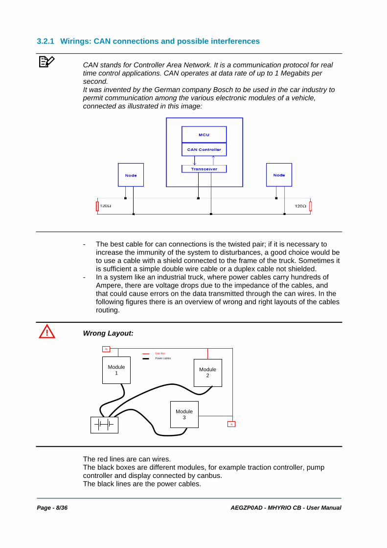
4 CAN stands for Controller Area Network. It is a communication protocol for real time control applications. CAN operates at data rate of up to 1 Megabits per second. It was invented by the German company Bosch to be used in the car industry to permit communication among the various electronic modules of a vehicle, connected as illustrated in this image:
- The best cable for can connections is the twisted pair; if it is necessary to increase the immunity of the system to disturbances, a good choice would be to use a cable with a shield connected to the frame of the truck. Sometimes it is sufficient a simple double wire cable or a duplex cable not shielded.
- In a system like an industrial truck, where power cables carry hundreds of Ampere, there are voltage drops due to the impedance of the cables, and that could cause errors on the data transmitted through the can wires. In the following figures there is an overview of wrong and right layouts of the cables routing.
U Wrong Layout:
The red lines are can wires. The black boxes are different modules, for example traction controller, pump controller and display connected by canbus. The black lines are the power cables.
Module
1
Module
3
Module
2
R
R
Can Bus
Power cables
AEGZP0AD - MHYRIO CB - User Manual Page - 9/36
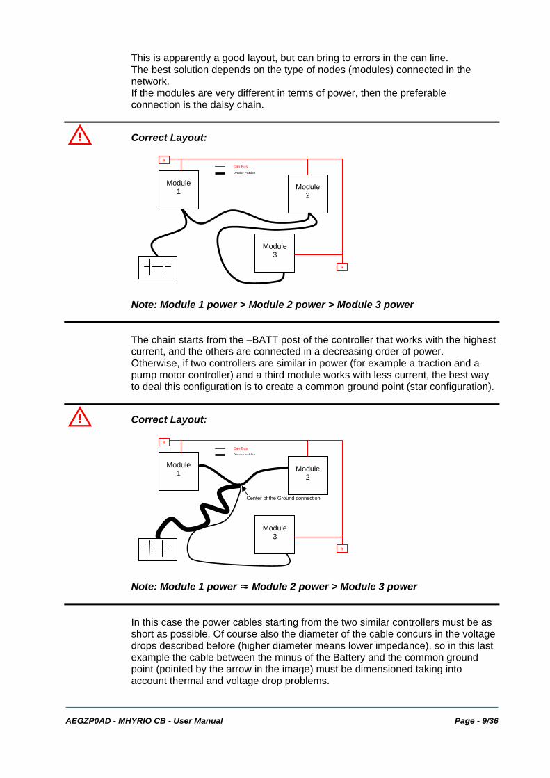
This is apparently a good layout, but can bring to errors in the can line. The best solution depends on the type of nodes (modules) connected in the network. If the modules are very different in terms of power, then the preferable connection is the daisy chain.
U Correct Layout:
Note: Module 1 power > Module 2 power > Module 3 power
The chain starts from the –BATT post of the controller that works with the highest current, and the others are connected in a decreasing order of power. Otherwise, if two controllers are similar in power (for example a traction and a pump motor controller) and a third module works with less current, the best way to deal this configuration is to create a common ground point (star configuration).
U Correct Layout:
Note: Module 1 power ≈ Module 2 power > Module 3 power
In this case the power cables starting from the two similar controllers must be as short as possible. Of course also the diameter of the cable concurs in the voltage drops described before (higher diameter means lower impedance), so in this last example the cable between the minus of the Battery and the common ground point (pointed by the arrow in the image) must be dimensioned taking into account thermal and voltage drop problems.
Module 1
Module 2
Module 3
R
R
Can Bus
Power cables
Center of the Ground connection
Module 1
Module 2
Module 3
R
R
Can Bus
Power cables
Page - 10/36 AEGZP0AD - MHYRIO CB - User Manual
4 Can advantages The complexity of today systems needs more and more data, signal and information must flow from a node to another. CAN is the solution to different problems that arise from this complexity - simplified design (readily available, multi sourced components and tools) - lower costs (less and smaller cables ) - improved reliability (fewer connections) - analysis of problems improved (easy connection with a pc to read the data flowing through the cable).
3.2.2 Wirings: I/O connections - After crimping the cable, verify that all strands are entrapped in the wire
barrel. - Verify that all the crimped contacts are completely inserted on the connector
cavities.
U A cable connected to the wrong pin can lead to short circuits and failure; so, before turning on the truck for the first time, verify with a multimeter the continuity between the starting point and the end of a signal wire.
- For information about the mating connector pin assignment see the paragraph “description of the connectors”.
3.2.3 Insulation of truck frame
U As stated by EN-1175 “Safety of machinery – Industrial truck”, chapter 5.7, “there shall be no electrical connection to the truck frame”. So the truck frame has to be isolated from any electrical potential of the truck power line.
3.3 Protection and safety features
3.3.1 Protection features - Battery polarity inversion
It is necessary to fit a MAIN CONTACTOR to protect the MHYRIO against reverse battery polarity and for safety reasons.
- Connection Errors: All inputs are protected against connection errors.
- External agents: The controller is protected against dust and the spray of liquid to a degree of protection meeting IP65.
3.3.2 Safety Features
U ZAPI controllers are designed according to the prEN954-1 specifications for
AEGZP0AD - MHYRIO CB - User Manual Page - 11/36
safety related parts of control system and to UNI EN1175-1 norm.
U The safety of the machine is strongly related to installation; length, layout and screening of electrical connections have to be carefully designed. ZAPI is always available to cooperate with the customer in order to evaluate installation and connection solutions. Furthermore, ZAPI is available to develop new SW or HW solutions to improve the safety of the machine, according to customer requirements. Machine manufacturer holds the responsibility for the truck safety features and related approval.
The positive of EVs coils (outputs C16, C17, C18 for ON/OFF VALVES; outputs C20, C2, C5, C8, C13 for proportional valves) comes from the valve positive voltage supply (input B2), being controlled by an electronic high-side switch. In this way, Mhyrio CB is able to open not only the negative side of the valve coil, but also the positive side. The positive for valves (input B2), can be independent from the Mhyrio CB power supply. It is strongly suggested that valve positive is cut by a device controller by another intelligent module, which is thus able to open the valves positive in case of Mhyrio failures or malfunctioning. Thus the more safe solution is: - PEV supplied to B2, controlled by another intelligent module. - Positive of the valves taken from the PEV (1, 2, 3) and PEVP (1/2, 3/4,
5/6, 7/8, 9) outputs.
3.4 EMC
U EMC and ESD performances of an electronic system are strongly influenced by the installation. Special attention must be given to the lengths and the paths of the electric connections and the shields. This situation is beyond ZAPI's control. Zapi can offer assistance and suggestions, based on its years experience, on EMC related items. However, ZAPI declines any responsibility for non-compliance, malfunctions and failures, if correct testing is not made. The machine manufacturer holds the responsibility to carry out machine validation, based on existing norms (EN12895 for industrial truck; EN50081-2 for other applications).
EMC stands for Electromagnetic Compatibility, and it represents the studies and the tests on the electromagnetic energy generated or received by an electrical device. So the analysis works in two directions: 1) The study of the emission problems, the disturbances generated by the
device and the possible countermeasure to prevent the propagation of that energy; we talk about “conduction” issues when guiding structures such as wires and cables are involved, “radiated emissions” issues when it is studied the propagation of electromagnetic energy through the open space. In our
Page - 12/36 AEGZP0AD - MHYRIO CB - User Manual
case the origin of the disturbances can be found inside the controller with the switching of the mosfets which are working at high frequency and generate RF energy, but wires and cables have the key role to propagate the disturbs because they works as antennas, so a good layout of the cables and their shielding can solve the majority of the emission problems.
2) The study of the immunity can be divided in two main branches: protection
from electromagnetic fields and from electrostatic discharge. The electromagnetic immunity concern the susceptibility of the controller with regard to electromagnetic fields and their influence on the correct work made by the electronic device. There are well defined tests which the machine has to be exposed to. These tests are carried out at determined levels of electromagnetic fields, to simulate external undesired disturbances and verify the electronic devices response.
3) The second type of immunity, ESD, concerns the prevention of the effects of
electric current due to excessive electric charge stored in an object. In fact, when a charge is created on a material and it remains there, it becomes an “electrostatic charge”; ESD happens when there is a rapid transfer from a charged object to another. This rapid transfer has, in turn, two important effects: A) this rapid charge transfer can determine, by induction, disturbs on the
signal wiring and thus create malfunctions; this effect is particularly critical in modern machines, with serial communications (canbus) which are spread everywhere on the truck and which carry critical information.
B) in the worst case and when the amount of charge is very high, the discharge process can determine failures in the electronic devices; the type of failure can vary from an intermittently malfunction to a completely failure of the electronic device.
IMPORTANT NOTE: it is always much easier and cheaper to avoid ESD from being generated, than to increase the level of immunity of the electronic devices. There are different solutions for EMC issues, depending on level of emissions/ immunity required, the type of controller, materials and position of the wires and electronic components. 1) EMISSIONS. Three ways can be followed to reduce the emissions:
A) SOURCE OF EMISSIONS: finding the main source of disturb and work on it.
B) SHIELDING: enclosing contactor and controller in a shielded box; using shielded cables;
C) LAYOUT: a good layout of the cables can minimize the antenna effect; cables running nearby the truck frame or in iron channels connected to truck frames is generally a suggested not expensive solution to reduce the emission level.
2) ELECTROMAGNETIC IMMUNITY. The considerations made for emissions
are valid also for immunity. Additionally, further protection can be achieved with ferrite beads and bypass capacitors.
3) ELECTROSTATIC IMMUNITY. Three ways can be followed to prevent

AEGZP0AD - MHYRIO CB - User Manual Page - 13/36
damages from ESD:
A) PREVENTION: when handling ESD-sensitive electronic parts, ensure the operator is grounded; test grounding devices on a daily basis for correct functioning; this precaution is particularly important during controller handling in the storing and installation phase.
B) ISOLATION: use anti-static containers when transferring ESD-sensitive material.
C) GROUNDING: when a complete isolation cannot be achieved, a good grounding can divert the discharge current trough a “safe” path; the frame of a truck can works like a “local earth ground”, absorbing excess charge. So it is strongly suggested to connect to truck frame all the parts of the truck which can be touched by the operator, who is most of the time the source of ESD.
Page - 14/36 AEGZP0AD - MHYRIO CB - User Manual
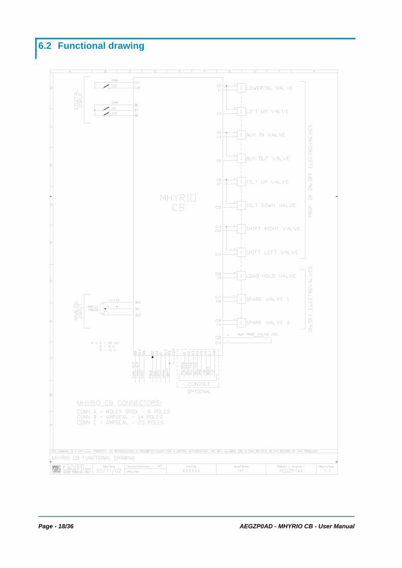
4 OPERATIONAL FEATURES Mhyrio CB has been designed to work on a CANBUS system. So, it follows the commands received by CAN communication and broadcasts the input status on the CAN. 8 of the 9 proportional valves are separated in 4 groups used for 4 different functions. Only one valve of the group can be active. It is possible to activate more function at the same time. FUNCTION1 is related to EVP1 and 2 (outputs C1, C3); typically this
function is lowering/lifting. FUNCTION2 is related to EVP3 and 4 (outputs C4, C6); typically this
function is an auxiliary function. FUNCTION3 is related to EVP5 and 6 (outputs C7, C15); typically
this function is tilting fw/rev. FUNCTION4 is related to EVP7 and 8 (outputs C12, C14); typically
this function is shifting right/left. The 9th proportional valve is single and can be driven in parallel to the others proportional valves.
AEGZP0AD - MHYRIO CB - User Manual Page - 15/36
5 DESCRIPTION OF THE CONNECTORS
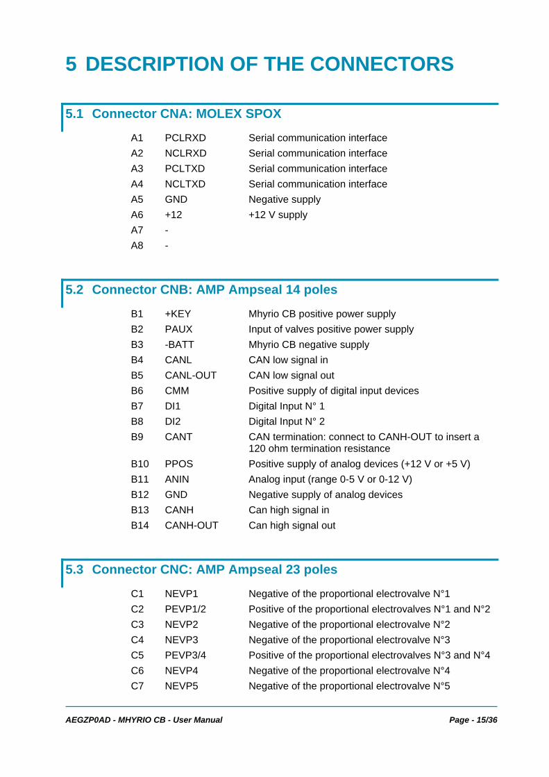
5.1 Connector CNA: MOLEX SPOX
A1 PCLRXD Serial communication interface A2 NCLRXD Serial communication interface A3 PCLTXD Serial communication interface A4 NCLTXD Serial communication interface A5 GND Negative supply A6 +12 +12 V supply A7 - A8 -
5.2 Connector CNB: AMP Ampseal 14 poles
B1 +KEY Mhyrio CB positive power supply B2 PAUX Input of valves positive power supply B3 -BATT Mhyrio CB negative supply B4 CANL CAN low signal in B5 CANL-OUT CAN low signal out B6 CMM Positive supply of digital input devices B7 DI1 Digital Input N° 1 B8 DI2 Digital Input N° 2 B9 CANT CAN termination: connect to CANH-OUT to insert a
120 ohm termination resistance B10 PPOS Positive supply of analog devices (+12 V or +5 V) B11 ANIN Analog input (range 0-5 V or 0-12 V) B12 GND Negative supply of analog devices B13 CANH Can high signal in B14 CANH-OUT Can high signal out
5.3 Connector CNC: AMP Ampseal 23 poles
C1 NEVP1 Negative of the proportional electrovalve N°1 C2 PEVP1/2 Positive of the proportional electrovalves N°1 and N°2 C3 NEVP2 Negative of the proportional electrovalve N°2 C4 NEVP3 Negative of the proportional electrovalve N°3 C5 PEVP3/4 Positive of the proportional electrovalves N°3 and N°4 C6 NEVP4 Negative of the proportional electrovalve N°4 C7 NEVP5 Negative of the proportional electrovalve N°5

Page - 16/36 AEGZP0AD - MHYRIO CB - User Manual
C8 PEVP5/6 Positive of the proportional electrovalves N°5 and N°6 C9 NEV1 Negative of the on/off electrovalve N°1 C10 NEV2 Negative of the on/off electrovalve N°2 C11 NEV3 Negative of the on/off electrovalve N°3 C12 NEVP7 Negative of the proportional electrovalve N°7 C13 PEVP7/8 Positive of the proportional electrovalves N°7 and N°8 C14 NEVP8 Negative of the proportional electrovalve N°8 C15 NEVP6 Negative of the proportional electrovalve N°6 C16 PEV1 Positive of the on/off electrovalve N°1 C17 PEV2 Positive of the on/off electrovalve N°2 C18 PEV3 Positive of the on/off electrovalve N°3 C19 NEVP Negative of the single proportional electrovalve C20 PEVP Positive of the single proportional electrovalve C21 CMM Positive supply of digital input devices C22 DI0 Digital input N°0 C23 -BATT Mhyrio CB negative supply
AEGZP0AD - MHYRIO CB - User Manual Page - 17/36
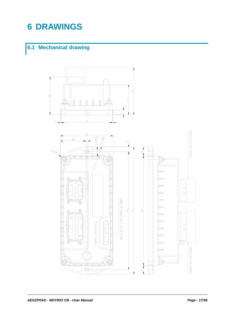
6 DRAWINGS
6.1 Mechanical drawing
Page - 18/36 AEGZP0AD - MHYRIO CB - User Manual
6.2 Functional drawing
AEGZP0AD - MHYRIO CB - User Manual Page - 19/36
7 PROGRAMMING & ADJUSTMENTS USING DIGITAL CONSOLE
7.1 Adjustments via console
Adjustment of Parameters and changes to the controller’s configuration are made using the Digital Console. Zapi console can be connected directly to Mhyrio CB (connector A), or it can be physically connected to another controller in the CANBUS net, then virtually connected to Mhyrio CB (which is node 9 of the net).
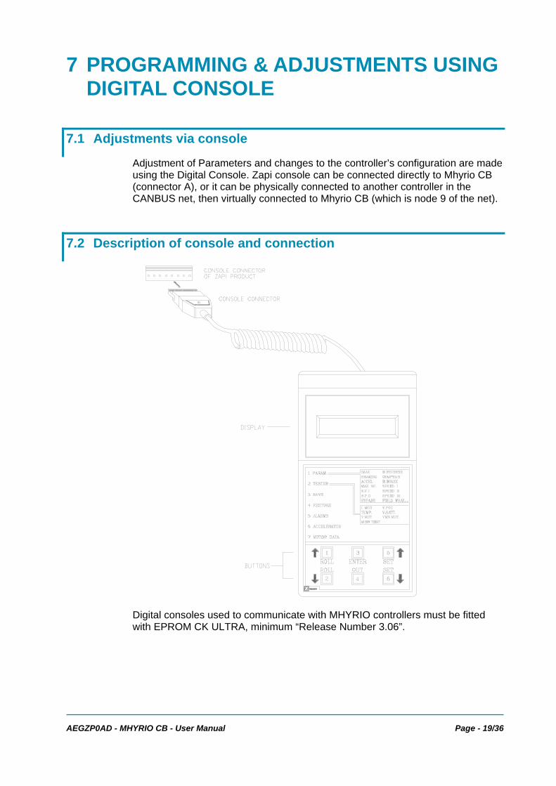
7.2 Description of console and connection
Digital consoles used to communicate with MHYRIO controllers must be fitted with EPROM CK ULTRA, minimum “Release Number 3.06”.
Page - 20/36 AEGZP0AD - MHYRIO CB - User Manual
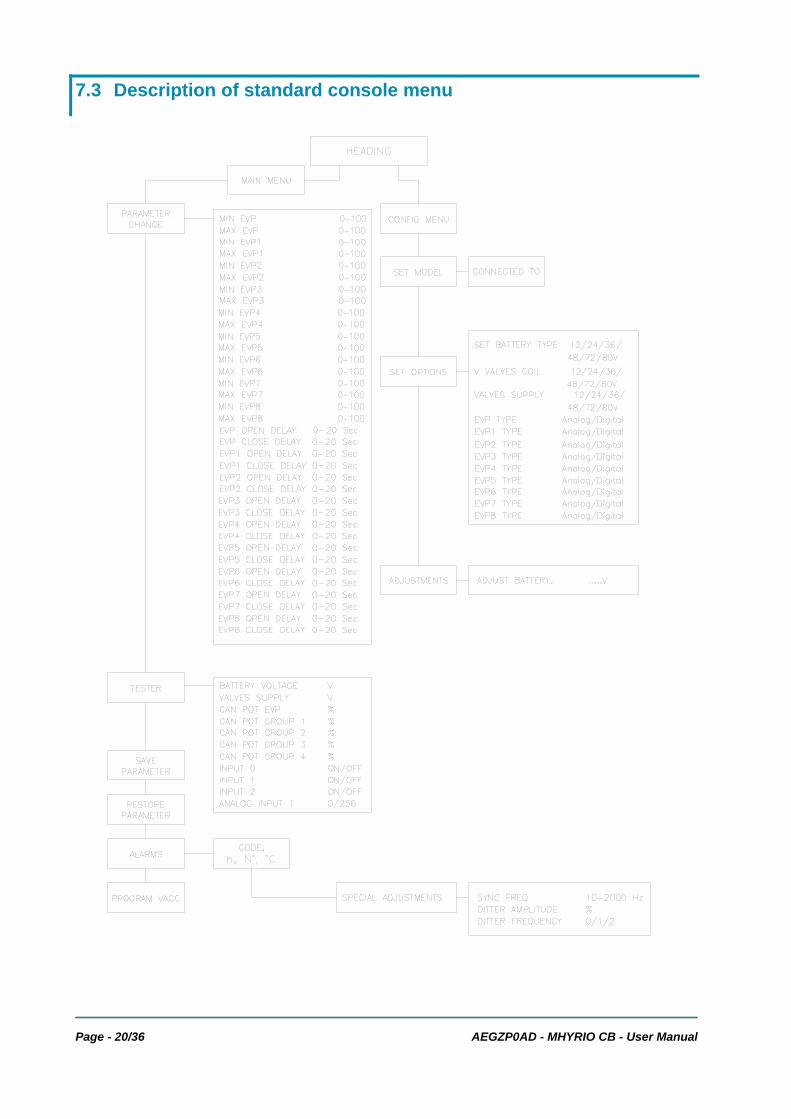
7.3 Description of standard console menu
AEGZP0AD - MHYRIO CB - User Manual Page - 21/36
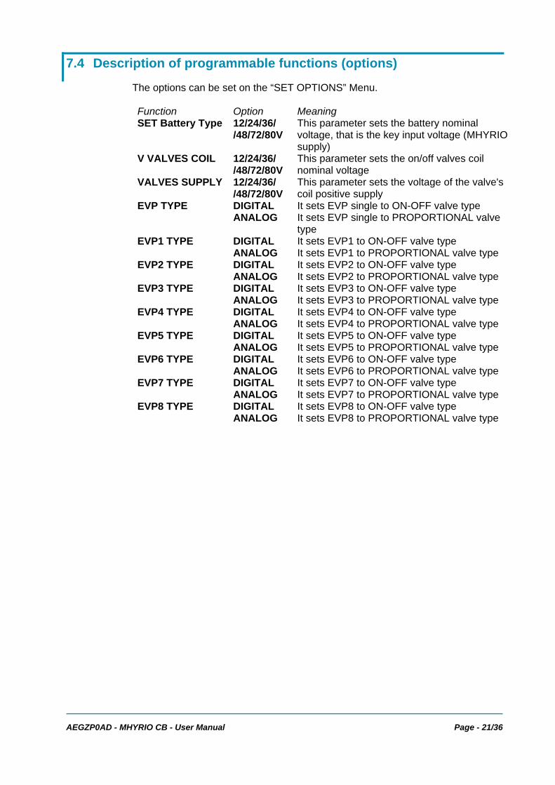
7.4 Description of programmable functions (options)
The options can be set on the “SET OPTIONS” Menu. Function Option Meaning SET Battery Type 12/24/36/
/48/72/80V This parameter sets the battery nominal voltage, that is the key input voltage (MHYRIO supply)
V VALVES COIL 12/24/36/ /48/72/80V
This parameter sets the on/off valves coil nominal voltage
VALVES SUPPLY 12/24/36/ /48/72/80V
This parameter sets the voltage of the valve's coil positive supply
EVP TYPE DIGITAL It sets EVP single to ON-OFF valve type ANALOG It sets EVP single to PROPORTIONAL valve
type EVP1 TYPE DIGITAL It sets EVP1 to ON-OFF valve type ANALOG It sets EVP1 to PROPORTIONAL valve type EVP2 TYPE DIGITAL It sets EVP2 to ON-OFF valve type ANALOG It sets EVP2 to PROPORTIONAL valve type EVP3 TYPE DIGITAL It sets EVP3 to ON-OFF valve type ANALOG It sets EVP3 to PROPORTIONAL valve type EVP4 TYPE DIGITAL It sets EVP4 to ON-OFF valve type ANALOG It sets EVP4 to PROPORTIONAL valve type EVP5 TYPE DIGITAL It sets EVP5 to ON-OFF valve type ANALOG It sets EVP5 to PROPORTIONAL valve type EVP6 TYPE DIGITAL It sets EVP6 to ON-OFF valve type ANALOG It sets EVP6 to PROPORTIONAL valve type EVP7 TYPE DIGITAL It sets EVP7 to ON-OFF valve type ANALOG It sets EVP7 to PROPORTIONAL valve type EVP8 TYPE DIGITAL It sets EVP8 to ON-OFF valve type ANALOG It sets EVP8 to PROPORTIONAL valve type
Page - 22/36 AEGZP0AD - MHYRIO CB - User Manual
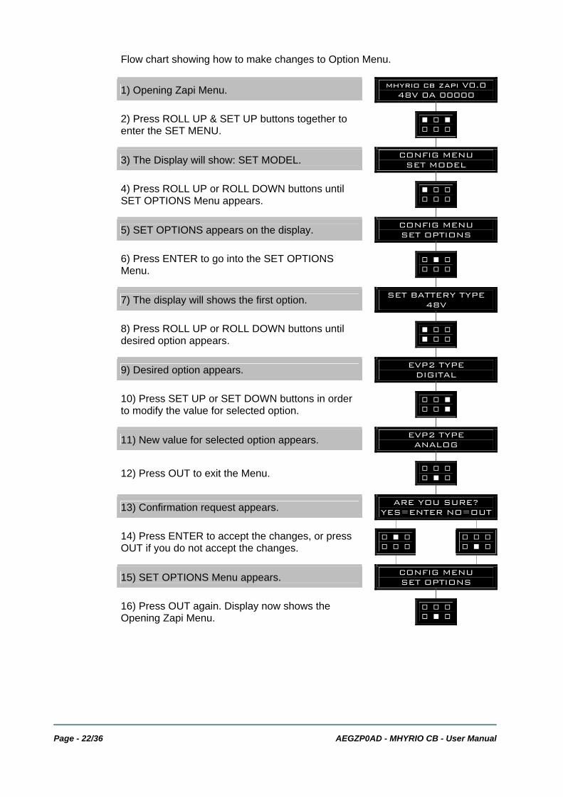
Flow chart showing how to make changes to Option Menu.
1) Opening Zapi Menu. mhyrio cb zapi V0.0 48V 0A 00000
2) Press ROLL UP & SET UP buttons together to enter the SET MENU. % ' %
' ' '
3) The Display will show: SET MODEL. CONFIG MENU SET MODEL
4) Press ROLL UP or ROLL DOWN buttons until SET OPTIONS Menu appears. % ' '
' ' '
5) SET OPTIONS appears on the display. CONFIG MENU SET OPTIONS
6) Press ENTER to go into the SET OPTIONS Menu. ' % '
' ' '
7) The display will shows the first option. SET BATTERY TYPE 48V
8) Press ROLL UP or ROLL DOWN buttons until desired option appears. % ' '
% ' '
9) Desired option appears. EVP2 TYPE DIGITAL
10) Press SET UP or SET DOWN buttons in order to modify the value for selected option. ' ' %
' ' %
11) New value for selected option appears. EVP2 TYPE ANALOG
12) Press OUT to exit the Menu. ' ' ' ' % '
13) Confirmation request appears. ARE YOU SURE? YES=ENTER NO=OUT
14) Press ENTER to accept the changes, or press OUT if you do not accept the changes. ' % '
' ' ' ' ' '' % '
15) SET OPTIONS Menu appears. CONFIG MENU SET OPTIONS
16) Press OUT again. Display now shows the Opening Zapi Menu. ' ' '
' % '
AEGZP0AD - MHYRIO CB - User Manual Page - 23/36
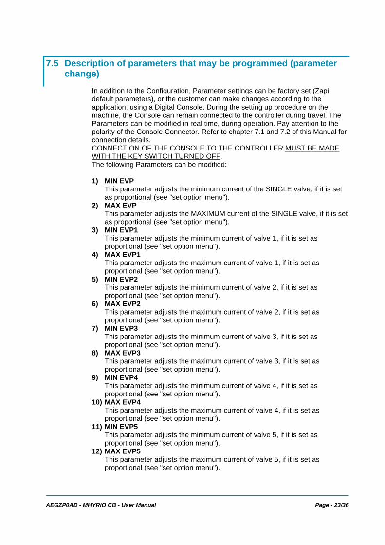
7.5 Description of parameters that may be programmed (parameter change)
In addition to the Configuration, Parameter settings can be factory set (Zapi default parameters), or the customer can make changes according to the application, using a Digital Console. During the setting up procedure on the machine, the Console can remain connected to the controller during travel. The Parameters can be modified in real time, during operation. Pay attention to the polarity of the Console Connector. Refer to chapter 7.1 and 7.2 of this Manual for connection details. CONNECTION OF THE CONSOLE TO THE CONTROLLER MUST BE MADE WITH THE KEY SWITCH TURNED OFF. The following Parameters can be modified: 1) MIN EVP
This parameter adjusts the minimum current of the SINGLE valve, if it is set as proportional (see "set option menu").
2) MAX EVP This parameter adjusts the MAXIMUM current of the SINGLE valve, if it is set as proportional (see "set option menu").
3) MIN EVP1 This parameter adjusts the minimum current of valve 1, if it is set as proportional (see "set option menu").
4) MAX EVP1 This parameter adjusts the maximum current of valve 1, if it is set as proportional (see "set option menu").
5) MIN EVP2 This parameter adjusts the minimum current of valve 2, if it is set as proportional (see "set option menu").
6) MAX EVP2 This parameter adjusts the maximum current of valve 2, if it is set as proportional (see "set option menu").
7) MIN EVP3 This parameter adjusts the minimum current of valve 3, if it is set as proportional (see "set option menu").
8) MAX EVP3 This parameter adjusts the maximum current of valve 3, if it is set as proportional (see "set option menu").
9) MIN EVP4 This parameter adjusts the minimum current of valve 4, if it is set as proportional (see "set option menu").
10) MAX EVP4 This parameter adjusts the maximum current of valve 4, if it is set as proportional (see "set option menu").
11) MIN EVP5 This parameter adjusts the minimum current of valve 5, if it is set as proportional (see "set option menu").
12) MAX EVP5 This parameter adjusts the maximum current of valve 5, if it is set as proportional (see "set option menu").

Page - 24/36 AEGZP0AD - MHYRIO CB - User Manual
13) MIN EVP6 This parameter adjusts the minimum current of valve 6, if it is set as proportional (see "set option menu").
14) MAX EVP6 This parameter adjusts the maximum current of valve 6, if it is set as proportional (see "set option menu").
15) MIN EVP7 This parameter adjusts the minimum current of valve 7, if it is set as proportional (see "set option menu").
16) MAX EVP7 This parameter adjusts the maximum current of valve 7, if it is set as proportional (see "set option menu").
17) MIN EVP8 This parameter adjusts the minimum current of valve 8, if it is set as proportional (see "set option menu").
18) MAX EVP8 This parameter adjusts the maximum current of valve 8, if it is set as proportional (see "set option menu").
19) EVP OPEN DELAY Single proportional valve current ramping up time: this parameter sets the single valve current ramp, to change from 0 A to operating current.
20) EVP CLOSE DELAY Single proportional valve current ramping down time: this parameter sets the single valve closing ramp, to change from operating current to 0 A.
21) EVP1 OPEN DELAY EVP1 proportional valve current ramping up time: this parameter sets the EVP1 valve current ramp, to change from 0 A to operating current.
22) EVP1 CLOSE DELAY EVP1 proportional valve current ramping down time: this parameter sets the EVP1 valve closing ramp, to change the coil current from operating current to 0 A.
23) EVP2 OPEN DELAY EVP2 proportional valve current ramping up time: this parameter sets the EVP2 valve current ramp, to change from 0 A to operating current.
24) EVP2 CLOSE DELAY EVP2 proportional valve current ramping down time: this parameter sets the EVP2 valve closing ramp, to change the coil current from operating current to 0 A.
25) EVP3 OPEN DELAY EVP3 proportional valve current ramping up time: this parameter sets the EVP3 valve current ramp, to change from 0 A to operating current.
26) EVP3 CLOSE DELAY EVP3 proportional valve current ramping down time: this parameter sets the EVP3 valve closing ramp, to change the coil current from operating current to 0 A.
27) EVP4 OPEN DELAY EVP4 proportional valve current ramping up time: this parameter sets the EVP4 valve current ramp, to change from 0 A to operating current.
28) EVP4 CLOSE DELAY EVP4 proportional valve current ramping down time: this parameter sets the EVP4 valve closing ramp, to change the coil current from operating current to 0 A.
29) EVP5 OPEN DELAY EVP5 proportional valve current ramping up time: this parameter sets the EVP5 valve current ramp, to change from 0 A to operating current.
AEGZP0AD - MHYRIO CB - User Manual Page - 25/36
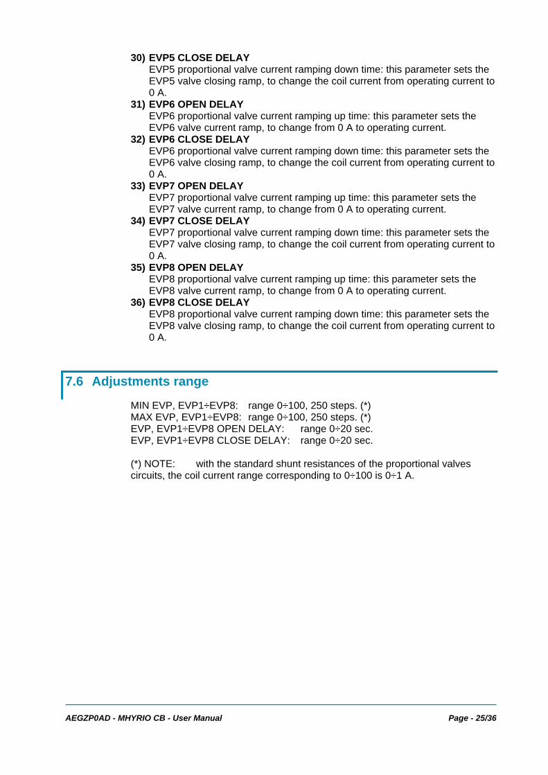
30) EVP5 CLOSE DELAY EVP5 proportional valve current ramping down time: this parameter sets the EVP5 valve closing ramp, to change the coil current from operating current to 0 A.
31) EVP6 OPEN DELAY EVP6 proportional valve current ramping up time: this parameter sets the EVP6 valve current ramp, to change from 0 A to operating current.
32) EVP6 CLOSE DELAY EVP6 proportional valve current ramping down time: this parameter sets the EVP6 valve closing ramp, to change the coil current from operating current to 0 A.
33) EVP7 OPEN DELAY EVP7 proportional valve current ramping up time: this parameter sets the EVP7 valve current ramp, to change from 0 A to operating current.
34) EVP7 CLOSE DELAY EVP7 proportional valve current ramping down time: this parameter sets the EVP7 valve closing ramp, to change the coil current from operating current to 0 A.
35) EVP8 OPEN DELAY EVP8 proportional valve current ramping up time: this parameter sets the EVP8 valve current ramp, to change from 0 A to operating current.
36) EVP8 CLOSE DELAY EVP8 proportional valve current ramping down time: this parameter sets the EVP8 valve closing ramp, to change the coil current from operating current to 0 A.
7.6 Adjustments range
MIN EVP, EVP1÷EVP8: range 0÷100, 250 steps. (*) MAX EVP, EVP1÷EVP8: range 0÷100, 250 steps. (*) EVP, EVP1÷EVP8 OPEN DELAY: range 0÷20 sec. EVP, EVP1÷EVP8 CLOSE DELAY: range 0÷20 sec. (*) NOTE: with the standard shunt resistances of the proportional valves circuits, the coil current range corresponding to 0÷100 is 0÷1 A.
Page - 26/36 AEGZP0AD - MHYRIO CB - User Manual
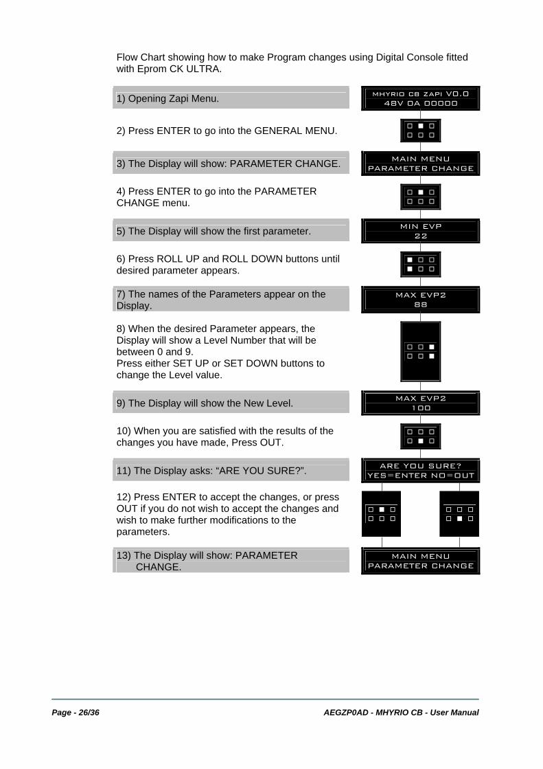
Flow Chart showing how to make Program changes using Digital Console fitted with Eprom CK ULTRA.
1) Opening Zapi Menu. mhyrio cb zapi V0.0 48V 0A 00000
2) Press ENTER to go into the GENERAL MENU. ' % ' ' ' '
3) The Display will show: PARAMETER CHANGE. MAIN MENU PARAMETER CHANGE
4) Press ENTER to go into the PARAMETER CHANGE menu. ' % '
' ' '
5) The Display will show the first parameter. MIN EVP 22
6) Press ROLL UP and ROLL DOWN buttons until desired parameter appears. % ' '
% ' '
7) The names of the Parameters appear on the Display. MAX EVP2
88
8) When the desired Parameter appears, the Display will show a Level Number that will be between 0 and 9. Press either SET UP or SET DOWN buttons to change the Level value.
' ' % ' ' %
9) The Display will show the New Level. MAX EVP2 100
10) When you are satisfied with the results of the changes you have made, Press OUT. ' ' '
' % '
11) The Display asks: “ARE YOU SURE?”. ARE YOU SURE? YES=ENTER NO=OUT
12) Press ENTER to accept the changes, or press OUT if you do not wish to accept the changes and wish to make further modifications to the parameters.
' % ' ' ' '
' ' ' ' % '
13) The Display will show: PARAMETER
CHANGE. MAIN MENU PARAMETER CHANGE

AEGZP0AD - MHYRIO CB - User Manual Page - 27/36
7.7 Special Adjustment menu
In the Special Adjustments menu (which is a submenu of the Alarm menu), it is possible to adjust the following parameters: 1) SYNC FREQ
It is the carrier frequency of the proportional valve coils drivers. The default value is 1000 Hz, it can be adjusted in the 10 to 2000 Hz. The resolution is 10 Hz (it can be adjusted in steps of 10 Hz).
2) DITTER AMPLITUDE It is the dither signal amplitude. The dither signal is a square wave which is superposed to the proportional valves set point. In this way the proportional valves response to set point variations is optimized. This parameter is a percentage of the valves maximum current. It can be adjusted in the 0% to 20.3% by nine levels. Setting the parameter to 0% means the dither isn’t used.
3) DITTER FREQUENCY It is the dither signal frequency. It can be used one of three: - 0: the dither signal frequency is 62.5 Hz - 1: the dither signal frequency is 83 Hz - 2: the dither signal frequency is 125 Hz.
7.8 Tester menu
Following parameters can be measured in real time in the TESTER menu: 1) BATTERY VOLTAGE
Level of battery voltage measured at the input of the key switch. 2) VALVES SUPPLY
Level of voltage at the positive valve supply input (B2). 3) CAN POT EVP
Single proportional valve current set point, received by canbus. 4) CAN POT GROUP 1
Group 1 proportional valves current set point, received by canbus. 5) CAN POT GROUP 2
Group 2 proportional valves current set point, received by canbus. 6) CAN POT GROUP 3
Group 3 proportional valves current set point, received by canbus. 7) CAN POT GROUP 4
Group 4 proportional valves current set point, received by canbus. 8) INPUT 0
Level of DIGITAL INPUT 0: - ON / +VB: input active, switch closed - OFF / COND: input not active, switch open.
9) INPUT 1 Level of DIGITAL INPUT 1: - ON / +VB: input active, switch closed - OFF / COND: input not active, switch open.
10) INPUT 2 Level of DIGITAL INPUT 2: - ON / +VB: input active, switch closed

Page - 28/36 AEGZP0AD - MHYRIO CB - User Manual
- OFF / COND: input not active, switch open. 11) ANALOG INPUT 1
Voltage of the analog input.
AEGZP0AD - MHYRIO CB - User Manual Page - 29/36
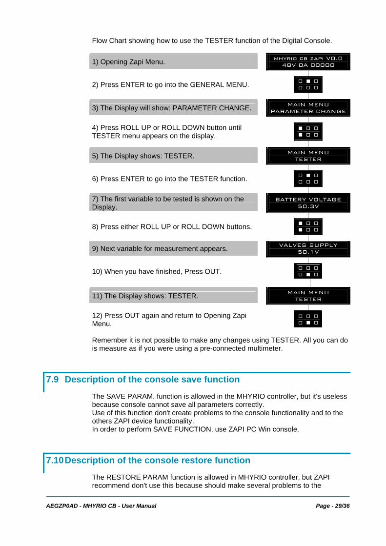
Flow Chart showing how to use the TESTER function of the Digital Console.
1) Opening Zapi Menu. mhyrio cb zapi V0.0 48V 0A 00000
2) Press ENTER to go into the GENERAL MENU. ' % ' ' ' '
3) The Display will show: PARAMETER CHANGE. MAIN MENU PARAMETER CHANGE
4) Press ROLL UP or ROLL DOWN button until TESTER menu appears on the display. % ' '
% ' '
5) The Display shows: TESTER. MAIN MENU TESTER
6) Press ENTER to go into the TESTER function. ' % ' ' ' '
7) The first variable to be tested is shown on the Display. BATTERY VOLTAGE
50.3V
8) Press either ROLL UP or ROLL DOWN buttons. % ' ' % ' '
9) Next variable for measurement appears. VALVES SUPPLY 50.1V
10) When you have finished, Press OUT. ' ' ' ' % '
11) The Display shows: TESTER. MAIN MENU TESTER
12) Press OUT again and return to Opening Zapi Menu.
' ' ' ' % '
Remember it is not possible to make any changes using TESTER. All you can do is measure as if you were using a pre-connected multimeter.
7.9 Description of the console save function
The SAVE PARAM. function is allowed in the MHYRIO controller, but it's useless because console cannot save all parameters correctly. Use of this function don't create problems to the console functionality and to the others ZAPI device functionality. In order to perform SAVE FUNCTION, use ZAPI PC Win console.
7.10 Description of the console restore function
The RESTORE PARAM function is allowed in MHYRIO controller, but ZAPI recommend don't use this because should make several problems to the
Page - 30/36 AEGZP0AD - MHYRIO CB - User Manual
controller. As a result of using this function, all parameters will be overwritten with incorrectly values and MHYRIO controller will not work correctly. In order to perform RESTORE FUNCTION, use ZAPI PC Win console.
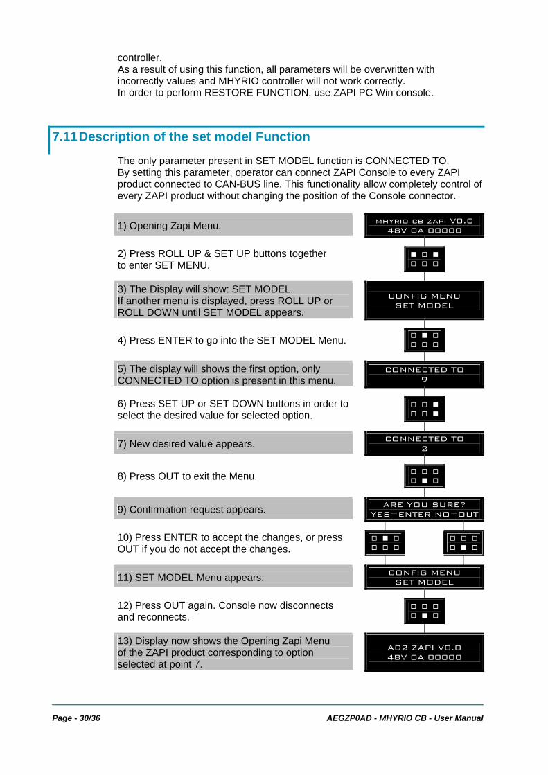
7.11 Description of the set model Function
The only parameter present in SET MODEL function is CONNECTED TO. By setting this parameter, operator can connect ZAPI Console to every ZAPI product connected to CAN-BUS line. This functionality allow completely control of every ZAPI product without changing the position of the Console connector.
1) Opening Zapi Menu. mhyrio cb zapi V0.0 48V 0A 00000
2) Press ROLL UP & SET UP buttons together to enter SET MENU. % ' %
' ' '
3) The Display will show: SET MODEL. If another menu is displayed, press ROLL UP or ROLL DOWN until SET MODEL appears.
CONFIG MENU SET MODEL
4) Press ENTER to go into the SET MODEL Menu. ' % ' ' ' '
5) The display will shows the first option, only CONNECTED TO option is present in this menu. CONNECTED TO
9
6) Press SET UP or SET DOWN buttons in order to select the desired value for selected option. ' ' %
' ' %
7) New desired value appears. CONNECTED TO 2
8) Press OUT to exit the Menu. ' ' ' ' % '
9) Confirmation request appears. ARE YOU SURE? YES=ENTER NO=OUT
10) Press ENTER to accept the changes, or press OUT if you do not accept the changes. ' % '
' ' ' ' ' '' % '
11) SET MODEL Menu appears. CONFIG MENU SET MODEL
12) Press OUT again. Console now disconnects and reconnects. ' ' '
' % '
13) Display now shows the Opening Zapi Menu of the ZAPI product corresponding to option selected at point 7.
AC2 ZAPI V0.0 48V 0A 00000

AEGZP0AD - MHYRIO CB - User Manual Page - 31/36
The table below indicates which parameter can be set to connect ZAPI products to Console.
PARAMETER CONNECTED PRODUCT 1 SICOS 2 TRACTION CONTROLLER 3 MASTER CONTROLLER 4 SLAVE CONTROLLER 5 PUMP CONTROLLER 6 EPS 9 MHYRIO
The range for this parameter is 0~32, but only above number are enabled. If operator selects a not specified value, ZAPI Console reconnects the product physically connected to Console. To have a confirmation of the product connected, see the console headline.
Page - 32/36 AEGZP0AD - MHYRIO CB - User Manual
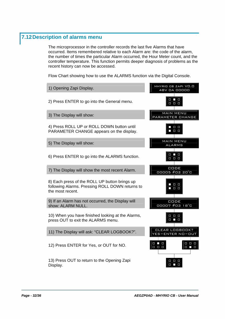
7.12 Description of alarms menu
The microprocessor in the controller records the last five Alarms that have occurred. Items remembered relative to each Alarm are: the code of the alarm, the number of times the particular Alarm occurred, the Hour Meter count, and the controller temperature. This function permits deeper diagnosis of problems as the recent history can now be accessed. Flow Chart showing how to use the ALARMS function via the Digital Console.
1) Opening Zapi Display. mhyrio cb zapi V0.0 48V 0A 00000
2) Press ENTER to go into the General menu. ' % ' ' ' '
3) The Display will show: MAIN MENU PARAMETER CHANGE
4) Press ROLL UP or ROLL DOWN button until PARAMETER CHANGE appears on the display. % ' '
% ' '
5) The Display will show: MAIN MENU ALARMS
6) Press ENTER to go into the ALARMS function. ' % ' ' ' '
7) The Display will show the most recent Alarm. CODE 00005 #02 20°C
8) Each press of the ROLL UP button brings up following Alarms. Pressing ROLL DOWN returns to the most recent.
% ' ' % ' '
9) If an Alarm has not occurred, the Display will show: ALARM NULL. CODE
00007 #03 18°C
10) When you have finished looking at the Alarms, press OUT to exit the ALARMS menu. ' ' '
' % '
11) The Display will ask: “CLEAR LOGBOOK?”. CLEAR LOGBOOK? YES=ENTER NO=OUT
12) Press ENTER for Yes, or OUT for NO. ' % ' ' ' '
' ' '' % '
13) Press OUT to return to the Opening Zapi Display. ' ' '
' % '
AEGZP0AD - MHYRIO CB - User Manual Page - 33/36
8 CONTROLLER DIAGNOSTIC
8.1 Analysis of alarms displayed on the console
1) EEPROM KO Fault in the area of memory where the adjustment parameters are stored. This Alarm does not inhibit machine operation but operation goes on with default values; if fault is still present when the Key Switch is re-cycled, replace the logic. If the fault disappears, the previously stored Parameters will have been replaced by the default parameters.
2) CAN BUS KO There is a problem related to the CAN-BUS line. The error is signalled if the MHYRIO controller does not receive any message from the CAN-BUS line. First of all, check the wiring. If it is ok, the problem is on the logic board, which must be replaced.
3) WATCHDOG The test is made in both running and standby. It is a self-diagnosing test within the logic. If an alarm should occur, replace the logic.
4) WRONG SET BATTERY This fault is signalled if the battery voltage is non consistent with the set battery programmed in the 'set option' menu.
5) UNDERVOLTAGE This fault is signalled if an undervoltage condition is detected in the MHYRIO power supply.
6) FF VALVES Flip-flop circuit, that manages on/off valve drivers short-circuit protection, does not reset in the correct way. The problem is probably in the hardware circuit.
7) COIL SHORTED ON/OFF valves drivers are protected against coil short circuit; if a short is present across the coil, the flip-flop circuit is set and the alarm is signalled.
8) EV DRIVER SHORT One of the on/off valves driver is shorted; check the external connection, if it is ok the driver is probably damaged.
9) EVP DRIVER SHORT The single proportional valve driver is shorted; check the external connection, if it is ok the driver is probably damaged.
10) EVPG1 DRIVER SHORT One of the Group 1 valves drivers is shorted; check the external connection, if it is ok the driver is probably damaged.
11) EVPG2 DRIVER SHORT One of the Group 2 valves drivers is shorted; check the external connection, if it is ok the driver is probably damaged.
12) EVPG3 DRIVER SHORT One of the Group 3 valves drivers is shorted; check the external connection, if it is ok the driver is probably damaged.
13) EVPG4 DRIVER SHORT One of the Group 4 valves drivers is shorted; check the external connection, if it is ok the driver is probably damaged.
14) EV DRIVER KO One of the On/Off valves drivers is open (it does not close when it is commanded by the microcontroller).

Page - 34/36 AEGZP0AD - MHYRIO CB - User Manual
15) EVP DRIVER KO The single proportional valve driver is open (it does not close when it is commanded by the microcontroller).
16) EVPG1 DRIVER KO One of the Group 1 valves drivers is open (it does not close when it is commanded by the microcontroller).
17) EVPG2 DRIVER KO One of the Group 2 valves drivers is open (it does not close when it is commanded by the microcontroller).
18) EVPG3 DRIVER KO One of the Group 3 valves drivers is open (it does not close when it is commanded by the microcontroller).
19) EVPG4 DRIVER KO One of the Group 4 valves drivers is open (it does not close when it is commanded by the microcontroller).
20) HI SIDEDRIVER KO The high side driver which supply the valves coils positive is shorted or open.
21) WAITING FOR PEV There isn’t the valves positive power supply. Check B2 input then verify the VALVES SUPPLY parameter is correctly set.

AEGZP0AD - MHYRIO CB - User Manual Page - 35/36
9 RECOMMENDED SPARE PARTS FOR CONTROLLER
Part Number Description C12531 Ampseal Connector 23 pins Female C12530 Ampseal Connector 14 pins Female C12796 Female ampseal pin harness side
Page - 36/36 AEGZP0AD - MHYRIO CB - User Manual
10 PERIODIC MAINTENANCE TO BE REPEATED AT TIMES INDICATED
Check the wear and condition of the Contactors’ moving and fixed contacts. Electrical Contacts should be checked every ....................................... 3 MONTHS Check the Foot pedal or Tiller microswitch. Using a suitable test meter, confirm that there is no electrical resistance between the contacts by measuring the volt drop between the terminals. Switches should operate with a firm click sound. Microswitches should be checked every .............................................. 3 MONTHS Check the Battery cables, cables to the controller and cables to the motor. Ensure the insulation is sound and the connections are tight. Cables should be checked every....................................................................................... 3 MONTHS Check the mechanical operation of the pedal or tiller. Are the return springs ok. Do the potentiometers wind up to their full or programmed level. Check every....... .............................................................................................................. 3 MONTHS Check the mechanical operation of the Contactor(s). Moving contacts should be free to move without restriction. Check every....................................... 3 MONTHS Checks should be carried out by qualified personnel only and any replacement parts used should be original. Beware of NON ORIGINAL PARTS. The installation of this electronic controller should be made according to the diagrams included in this Manual. Any variations or special requirements should be made after consulting a Zapi Agent. The supplier is not responsible for any problem that arises from wiring methods that differs from information included in this Manual. During periodic checks, if a technician finds any situation that could cause damage or compromise safety, the matter should be bought to the attention of a Zapi Agent immediately. The Agent will then take the decision regarding operational safety of the machine. Remember that Battery Powered Machines feel no pain. NEVER USE A VEHICLE WITH A FAULTY ELECTRONIC CONTROLLER.


![Mating Sound[2]](https://img.pdfslide.us/doc/110x75/577ce4b51a28abf1038efabf/mating-sound2.jpg)