Embed Size (px)
Citation preview
BIMBA BIM-HYD-0421 Catalog 2021 | For Technical Assistance: 800-442-4622
13
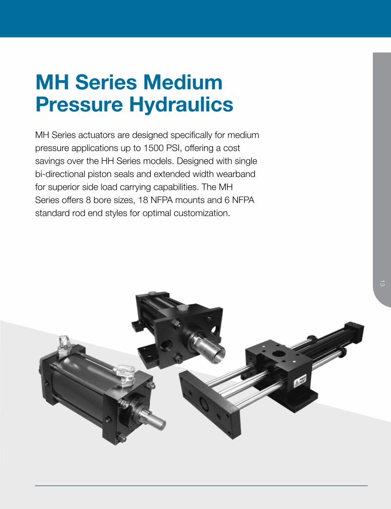
MH Series actuators are designed specifically for medium pressure applications up to 1500 PSI, offering a cost savings over the HH Series models. Designed with single bi-directional piston seals and extended width wearband for superior side load carrying capabilities. The MH Series offers 8 bore sizes, 18 NFPA mounts and 6 NFPA standard rod end styles for optimal customization.
MH Series Medium Pressure Hydraulics

BIMBA BIM-HYD-0421 Catalog 2021 | For Technical Assistance: 800-442-4622
14
Product Features
Contents
15 MH Series Medium Pressure Hydraulics
16 How it Works 16 – Port Locations 16 – Maximum Stroke 17 – Force Chart 18 – Torque Charts 19 – Weight Chart
20 How to Specify, Dimensions 20 – NFPA Mounting Styles 21 – Threads 22 – Basic Cylinder 24 – Trunnion Mounts 26 – Extended Tie Rod Mounts 28 – Flange Mounts 31 – Spherical Bearing Mount 32 – Lug Mounts 34 – Bottom Mounts 36 – Pivot Mounts 38 – Double Rod End Mounts
50 How to Order 50 – Cylinder 51 – Seal Kits
52 Options
BIMBA BIM-HYD-0421 Catalog 2021 | For Technical Assistance: 800-442-4622
1515
Product FeaturesM
H SERIES M
EDIUM
PRESSURE HYD
RAULICS
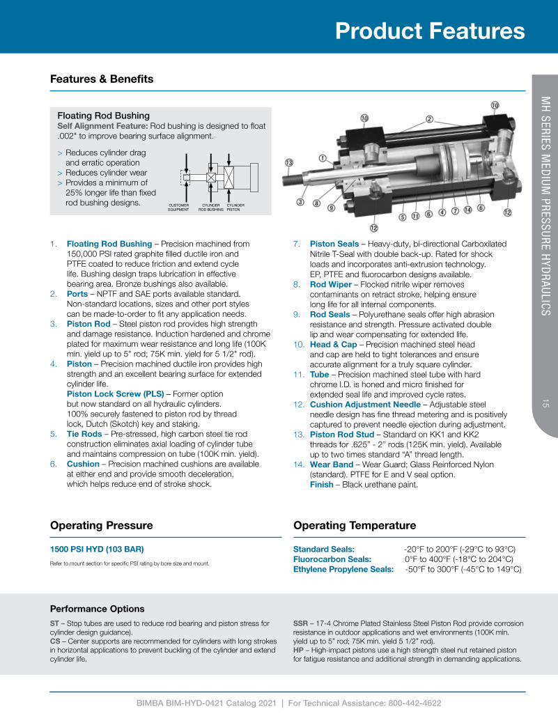
Features & Benefits
1. Floating Rod Bushing – Precision machined from 150,000 PSI rated graphite filled ductile iron and PTFE coated to reduce friction and extend cycle life. Bushing design traps lubrication in effective bearing area. Bronze bushings also available.
2. Ports – NPTF and SAE ports available standard. Non-standard locations, sizes and other port styles can be made-to-order to fit any application needs.
3. Piston Rod – Steel piston rod provides high strength and damage resistance. Induction hardened and chrome plated for maximum wear resistance and long life (100K min. yield up to 5" rod; 75K min. yield for 5 1/2" rod).
4. Piston – Precision machined ductile iron provides high strength and an excellent bearing surface for extended cylinder life. Piston Lock Screw (PLS) – Former option but now standard on all hydraulic cylinders. 100% securely fastened to piston rod by thread lock, Dutch (Skotch) key and staking.
5. Tie Rods – Pre-stressed, high carbon steel tie rod construction eliminates axial loading of cylinder tube and maintains compression on tube (100K min. yield).
6. Cushion – Precision machined cushions are available at either end and provide smooth deceleration, which helps reduce end of stroke shock.
7. Piston Seals – Heavy-duty, bi-directional Carboxilated Nitrile T-Seal with double back-up. Rated for shock loads and incorporates anti-extrusion technology. EP, PTFE and fluorocarbon designs available.
8. Rod Wiper – Flocked nitrile wiper removes contaminants on retract stroke, helping ensure long life for all internal components.
9. Rod Seals – Polyurethane seals offer high abrasion resistance and strength. Pressure activated double lip and wear compensating for extended life.
10. Head & Cap – Precision machined steel head and cap are held to tight tolerances and ensure accurate alignment for a truly square cylinder.
11. Tube – Precision machined steel tube with hard chrome I.D. is honed and micro finished for extended seal life and improved cycle rates.
12. Cushion Adjustment Needle – Adjustable steel needle design has fine thread metering and is positively captured to prevent needle ejection during adjustment.
13. Piston Rod Stud – Standard on KK1 and KK2 threads for .625” - 2” rods (125K min. yield). Available up to two times standard “A” thread length.
14. Wear Band – Wear Guard; Glass Reinforced Nylon (standard). PTFE for E and V seal option. Finish – Black urethane paint.
Performance OptionsST – Stop tubes are used to reduce rod bearing and piston stress for cylinder design guidance). CS – Center supports are recommended for cylinders with long strokes in horizontal applications to prevent buckling of the cylinder and extend cylinder life.
SSR – 17-4 Chrome Plated Stainless Steel Piston Rod provide corrosion resistance in outdoor applications and wet environments (100K min. yield up to 5” rod; 75K min. yield 5 1/2” rod). HP – High-impact pistons use a high strength steel nut retained piston for fatigue resistance and additional strength in demanding applications.
Floating Rod BushingSelf Alignment Feature: Rod bushing is designed to float .002" to improve bearing surface alignment.
> Reduces cylinder drag and erratic operation
> Reduces cylinder wear > Provides a minimum of 25% longer life than fixed rod bushing designs.
Operating Pressure Operating Temperature
1500 PSI HYD (103 BAR)
Refer to mount section for specific PSI rating by bore size and mount.
Standard Seals: -20°F to 200°F (-29°C to 93°C) Fluorocarbon Seals: 0°F to 400°F (-18°C to 204°C) Ethylene Propylene Seals: -50°F to 300°F (-45°C to 149°C)
BIMBA BIM-HYD-0421 Catalog 2021 | For Technical Assistance: 800-442-4622
16
How It Works
MH
SERIES MED
IUM PRESSURE H
YDRAULICS
Technical Data
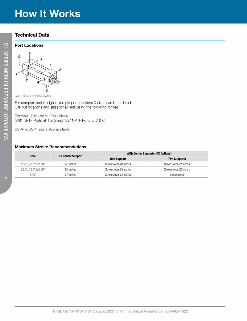
Bore No Center SupportWith Center Supports (CS Options)
One Support Two Supports
1.50", 2.00" & 2.50" 48 inches Strokes over 48 inches Strokes over 72 inches
3.25", 4.00" & 5.00" 65 inches Strokes over 65 inches Strokes over 92 inches
6.00" 72 inches Strokes over 72 inches not required
Maximum Stroke Recommendations
Note: Location 9 is center of cap face.
Port Locations
For complex port designs, multiple port locations & sizes can be ordered. Call out locations and sizes for all sets using the following format.
Example:-P15=N375 -P26=N500(3/8” NPTF Ports at 1 & 5 and 1/2” NPTF Ports at 2 & 6)
BSPP & BSPT ports also available.
BIMBA BIM-HYD-0421 Catalog 2021 | For Technical Assistance: 800-442-4622
1717
How It WorksM
H SERIES M
EDIUM
PRESSURE HYD
RAULICS
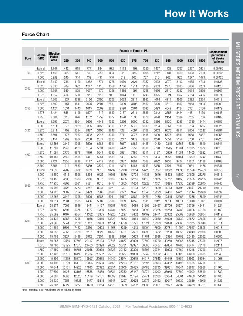
Force Chart
Note: Theoretical force. Actual force will be reduced by friction.
Bore
Rod Dia. (MM)
Effective Piston Area
Pounds of Force at PSI Displacement per Inches of Stroke (gallons)250 350 440 500 550 630 675 750 830 980 1000 1300 1500
1.50Extend 1.767 442 618 777 884 972 1113 1193 1325 1467 1732 1767 2297 2651 0.007650.625 1.460 365 511 642 730 803 920 986 1095 1212 1431 1460 1898 2190 0.006351.000 0.982 246 344 432 491 540 619 663 737 815 962 982 1277 1473 0.00425
2.00
Extend 3.142 786 1100 1382 1571 1728 1979 2121 2357 2608 3079 3142 4085 4713 0.01360.625 2.835 709 992 1247 1418 1559 1786 1914 2126 2353 2778 2835 3686 4253 0.01231.000 2.357 589 825 1037 1179 1296 1485 1591 1768 1956 2310 2357 3064 3536 0.01021.375 1.657 414 580 729 829 911 1044 1118 1243 1375 1624 1657 2154 2486 0.0071
2.50
Extend 4.909 1227 1718 2160 2455 2700 3093 3314 3682 4074 4811 4909 6382 7364 0.02130.625 4.602 1151 1611 2025 2301 2531 2899 3106 3452 3820 4510 4602 5983 6903 0.02001.000 4.124 1031 1443 1815 2062 2268 2598 2784 3093 3423 4042 4124 5361 6186 0.01791.375 3.424 856 1198 1507 1712 1883 2157 2311 2568 2842 3356 3424 4451 5136 0.01481.750 2.504 626 876 1102 1252 1377 1578 1690 1878 2078 2454 2504 3255 3756 0.0109
3.25
Extend 8.296 2074 2904 3650 4148 4563 5226 5600 6222 6886 8130 8296 10785 12444 0.03591.000 7.511 1878 2629 3305 3756 4131 4732 5070 5633 6234 7361 7511 9764 11267 0.03251.375 6.811 1703 2384 2997 3406 3746 4291 4597 5108 5653 6675 6811 8854 10217 0.02941.750 5.891 1473 2062 2592 2946 3240 3711 3976 4418 4890 5773 5891 7658 8837 0.02552.000 5.154 1289 1804 2268 2577 2835 3247 3479 3866 4278 5051 5154 6700 7731 0.0223
4.00
Extend 12.566 3142 4398 5529 6283 6911 7917 8482 9425 10430 12315 12566 16336 18849 0.05441.000 11.781 2945 4123 5184 5891 6480 7422 7952 8836 9778 11545 11781 15315 17672 0.05101.375 11.081 2770 3878 4876 5541 6095 6981 7480 8311 9197 10859 11081 14405 16622 0.04791.750 10.161 2540 3556 4471 5081 5589 6401 6859 7621 8434 9958 10161 13209 15242 0.04402.000 9.424 2356 3298 4147 4712 5183 5937 6361 7068 7822 9236 9424 12251 14136 0.04082.500 7.657 1914 2680 3369 3829 4211 4824 5168 5743 6355 7504 7657 9954 11486 0.0331
5.00
Extend 19.635 4909 6872 8639 9818 10799 12370 13254 14726 16297 19242 19635 25526 29453 0.08501.000 18.850 4713 6598 8294 9425 10368 11876 12724 14138 15646 18473 18850 24505 28275 0.08161.375 18.150 4538 6353 7986 9075 9983 11435 12251 13613 15065 17787 18150 23595 27225 0.07851.750 17.230 4308 6031 7581 8615 9477 10855 11630 12923 14301 16885 17230 22399 25845 0.07462.000 16.493 4123 5773 7257 8247 9071 10391 11133 12370 13689 16163 16493 21441 24740 0.07142.500 14.726 3682 5154 6479 7363 8099 9277 9940 11045 12223 14431 14726 19144 22089 0.06373.000 12.566 3142 4398 5529 6283 6911 7917 8482 9425 10430 12315 12566 16336 18849 0.05443.500 10.014 2504 3505 4406 5007 5508 6309 6759 7511 8312 9814 10014 13018 15021 0.0434
6.00
Extend 28.274 7069 9896 12441 14137 15551 17813 19085 21206 23467 27709 28274 36756 42411 0.12241.375 26.789 6697 9376 11787 13395 14734 16877 18083 20092 22235 26253 26789 34826 40184 0.11591.750 25.869 6467 9054 11382 12935 14228 16297 17462 19402 21471 25352 25869 33630 38804 0.01122.000 25.132 6283 8796 11058 12566 13823 15833 16964 18849 20860 24629 25132 32672 37698 0.10882.500 23.365 5841 8178 10281 11683 12851 14720 15771 17524 19393 22898 23365 30375 35048 0.10113.000 21.205 5301 7422 9330 10603 11663 13359 14313 15904 17600 20781 21205 27567 31808 0.09183.500 18.653 4663 6529 8207 9327 10259 11751 12591 13990 15482 18280 18653 24249 27980 0.08084.000 15.708 3927 5498 6912 7854 8639 9896 10603 11781 13038 15394 15708 20420 23562 0.0680
8.00
Extend 50.265 12566 17593 22117 25133 27646 31667 33929 37699 41720 49260 50265 65345 75398 0.21761.375 48.780 12195 17073 21463 24390 26829 30731 32927 36585 40487 47804 48780 63414 73170 0.21111.750 47.860 11965 16751 21058 23930 26323 30152 32306 35895 39724 46903 47860 62218 71790 0.20722.000 47.123 11781 16493 20734 23562 25918 29687 31808 35342 39112 46181 47123 61260 70685 0.20402.500 45.356 11339 15875 19957 22678 24946 28574 30615 34017 37645 44449 45356 58963 68034 0.19633.000 43.196 10799 15119 19006 21598 23758 27213 29157 32397 35853 42332 43196 56155 64794 0.18703.500 40.644 10161 14225 17883 20322 22354 25606 27435 30483 33735 39831 40644 52837 60966 0.17604.000 37.699 9425 13195 16588 18850 20734 23750 25447 28274 31290 36945 37699 49009 56549 0.16324.500 34.361 8590 12026 15119 17181 18899 21647 23194 25771 28520 33674 34361 44669 51542 0.14885.000 30.630 7658 10721 13477 15315 16847 19297 20675 22973 25423 30017 30630 39819 45945 0.13265.500 26.507 6627 9277 11663 13254 14579 16699 17892 19880 22001 25977 26507 34459 39761 0.1148
BIMBA BIM-HYD-0421 Catalog 2021 | For Technical Assistance: 800-442-4622
18
How It Works
MH
SERIES MED
IUM PRESSURE H
YDRAULICS
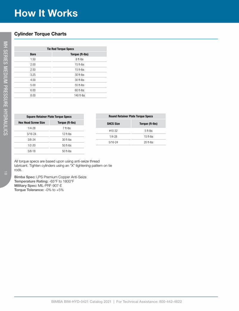
Cylinder Torque Charts
All torque specs are based upon using anti-seize thread lubricant. Tighten cylinders using an “X” tightening pattern on tie rods.
Bimba Spec: LPS Premium Copper Anti-Seize Temperature Rating: -65°F to 1800°F Military Spec: MIL-PRF-907-E Torque Tolerance: -0% to +5%
Tie Rod Torque Specs
Bore Torque (ft-lbs)
1.50 8 ft-lbs
2.00 15 ft-lbs
2.50 15 ft-lbs
3.25 30 ft-lbs
4.00 30 ft-lbs
5.00 55 ft-lbs
6.00 60 ft-lbs
8.00 140 ft-lbs
Square Retainer Plate Torque Specs
Hex Head Screw Size Torque (ft-lbs)
1/4-28 7 ft-lbs
5/16-24 12 ft-lbs
3/8-24 30 ft-lbs
1/2-20 50 ft-lbs
5/8-18 50 ft-lbs
Round Retainer Plate Torque Specs
SHCS Size Torque (ft-lbs)
#10-32 5 ft-lbs
1/4-28 15 ft-lbs
5/16-24 20 ft-lbs
BIMBA BIM-HYD-0421 Catalog 2021 | For Technical Assistance: 800-442-4622
1919
How It WorksM
H SERIES M
EDIUM
PRESSURE HYD
RAULICS
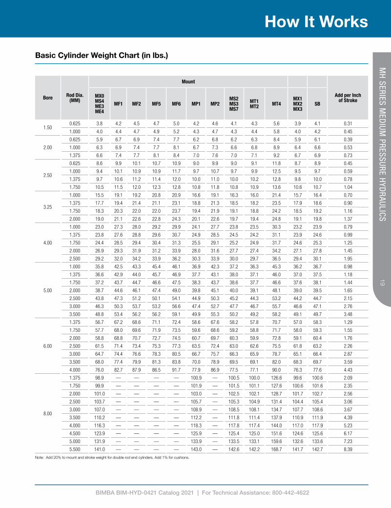
Basic Cylinder Weight Chart (in lbs.)
Bore Rod Dia. (MM)
Mount
Add per Inch of Stroke
MX0 MS4 ME3 ME4
MF1 MF2 MF5 MF6 MP1 MP2MS2 MS3 MS7
MT1 MT2 MT4
MX1 MX2 MX3
SB
1.500.625 3.8 4.2 4.5 4.7 5.0 4.2 4.6 4.1 4.3 5.6 3.9 4.1 0.31
1.000 4.0 4.4 4.7 4.9 5.2 4.3 4.7 4.3 4.4 5.8 4.0 4.2 0.45
2.00
0.625 5.9 6.7 6.9 7.4 7.7 6.2 6.8 6.2 6.3 8.4 5.9 6.1 0.39
1.000 6.3 6.9 7.4 7.7 8.1 6.7 7.3 6.6 6.8 8.9 6.4 6.6 0.53
1.375 6.6 7.4 7.7 8.1 8.4 7.0 7.6 7.0 7.1 9.2 6.7 6.9 0.73
2.50
0.625 8.6 9.9 10.1 10.7 10.9 9.0 9.9 9.0 9.1 11.8 8.7 8.9 0.45
1.000 9.4 10.1 10.9 10.9 11.7 9.7 10.7 9.7 9.9 12.5 9.5 9.7 0.59
1.375 9.7 10.6 11.2 11.4 12.0 10.0 11.0 10.0 10.2 12.8 9.8 10.0 0.78
1.750 10.5 11.5 12.0 12.3 12.8 10.8 11.8 10.8 10.9 13.6 10.6 10.7 1.04
3.25
1.000 15.5 19.1 19.2 20.8 20.9 16.6 19.1 16.3 16.0 21.4 15.7 16.4 0.70
1.375 17.7 19.4 21.4 21.1 23.1 18.8 21.3 18.5 18.2 23.5 17.9 18.6 0.90
1.750 18.3 20.3 22.0 22.0 23.7 19.4 21.9 19.1 18.8 24.2 18.5 19.2 1.16
2.000 19.0 21.1 22.6 22.8 24.3 20.1 22.6 19.7 19.4 24.8 19.1 19.8 1.37
4.00
1.000 23.0 27.3 28.0 29.2 29.9 24.1 27.7 23.8 23.5 30.3 23.2 23.9 0.79
1.375 23.8 27.6 28.8 29.6 30.7 24.9 28.5 24.5 24.2 31.1 23.9 24.6 0.99
1.750 24.4 28.5 29.4 30.4 31.3 25.5 29.1 25.2 24.9 31.7 24.6 25.3 1.25
2.000 26.9 29.3 31.9 31.2 33.9 28.0 31.6 27.7 27.4 34.2 27.1 27.8 1.45
2.500 29.2 32.0 34.2 33.9 36.2 30.3 33.9 30.0 29.7 36.5 29.4 30.1 1.95
5.00
1.000 35.8 42.5 43.3 45.4 46.1 36.9 42.3 37.2 36.3 45.3 36.2 36.7 0.98
1.375 36.6 42.9 44.0 45.7 46.9 37.7 43.1 38.0 37.1 46.0 37.0 37.5 1.18
1.750 37.2 43.7 44.7 46.6 47.5 38.3 43.7 38.6 37.7 46.6 37.6 38.1 1.44
2.000 38.7 44.6 46.1 47.4 49.0 39.8 45.1 40.0 39.1 48.1 39.0 39.5 1.65
2.500 43.8 47.3 51.2 50.1 54.1 44.9 50.3 45.2 44.3 53.2 44.2 44.7 2.15
3.000 46.3 50.3 53.7 53.2 56.6 47.4 52.7 47.7 46.7 55.7 46.6 47.1 2.76
3.500 48.8 53.4 56.2 56.2 59.1 49.9 55.3 50.2 49.2 58.2 49.1 49.7 3.48
6.00
1.375 56.7 67.2 68.6 71.1 72.4 58.6 67.6 58.2 57.8 70.7 57.0 58.3 1.29
1.750 57.7 68.0 69.6 71.9 73.5 59.6 68.6 59.2 58.8 71.7 58.0 59.3 1.55
2.000 58.8 68.8 70.7 72.7 74.5 60.7 69.7 60.3 59.9 72.8 59.1 60.4 1.76
2.500 61.5 71.4 73.4 75.3 77.3 63.5 72.4 63.0 62.6 75.5 61.8 63.2 2.26
3.000 64.7 74.4 76.6 78.3 80.5 66.7 75.7 66.3 65.9 78.7 65.1 66.4 2.87
3.500 68.0 77.4 79.9 81.3 83.8 70.0 78.9 69.5 69.1 82.0 68.3 69.7 3.59
4.000 76.0 82.7 87.9 86.5 91.7 77.9 86.9 77.5 77.1 90.0 76.3 77.6 4.43
8.00
1.375 98.9 — — — — 100.9 — 100.5 100.0 126.6 99.6 100.6 2.09
1.750 99.9 — — — — 101.9 — 101.5 101.1 127.6 100.6 101.6 2.35
2.000 101.0 — — — — 103.0 — 102.5 102.1 128.7 101.7 102.7 2.56
2.500 103.7 — — — — 105.7 — 105.3 104.9 131.4 104.4 105.4 3.06
3.000 107.0 — — — — 108.9 — 108.5 108.1 134.7 107.7 108.6 3.67
3.500 110.2 — — — — 112.2 — 111.8 111.4 137.9 110.9 111.9 4.39
4.000 116.3 — — — — 118.3 — 117.8 117.4 144.0 117.0 117.9 5.23
4.500 123.9 — — — — 125.9 — 125.4 125.0 151.6 124.6 125.6 6.17
5.000 131.9 — — — — 133.9 — 133.5 133.1 159.6 132.6 133.6 7.23
5.500 141.0 — — — — 143.0 — 142.6 142.2 168.7 141.7 142.7 8.39
Note: Add 20% to mount and stroke weight for double rod end cylinders. Add 1% for cushions.
BIMBA BIM-HYD-0421 Catalog 2021 | For Technical Assistance: 800-442-4622
20
How to Specify
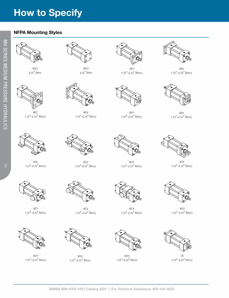
NFPA Mounting Styles
MP21.50”-6.00” Bores
MX01.50”-8.00” Bores
MF11.50”-6.00” Bores
MF21.50”-6.00” Bores
MF51.50”-6.00” Bores
MF61.50”-6.00” Bores
MP11.50”-8.00” Bores
ME38.00” Bore
ME48.00” Bore
SB1.50”-8.00” Bores
MS21.50”-8.00” Bores
MS31.50”-8.00” Bores
MS41.50”-8.00” Bores
MS71.50”-8.00” Bores
MT11.50”-8.00” Bores
MT21.50”-8.00” Bores
MT41.50”-8.00” Bores
MX11.50”-8.00” Bores
MX21.50”-8.00” Bores
MX31.50”-8.00” Bores
MH
SERIES MED
IUM PRESSURE H
YDRAULICS
BIMBA BIM-HYD-0421 Catalog 2021 | For Technical Assistance: 800-442-4622
2121
How to SpecifyM
H SERIES M
EDIUM
PRESSURE HYD
RAULICS
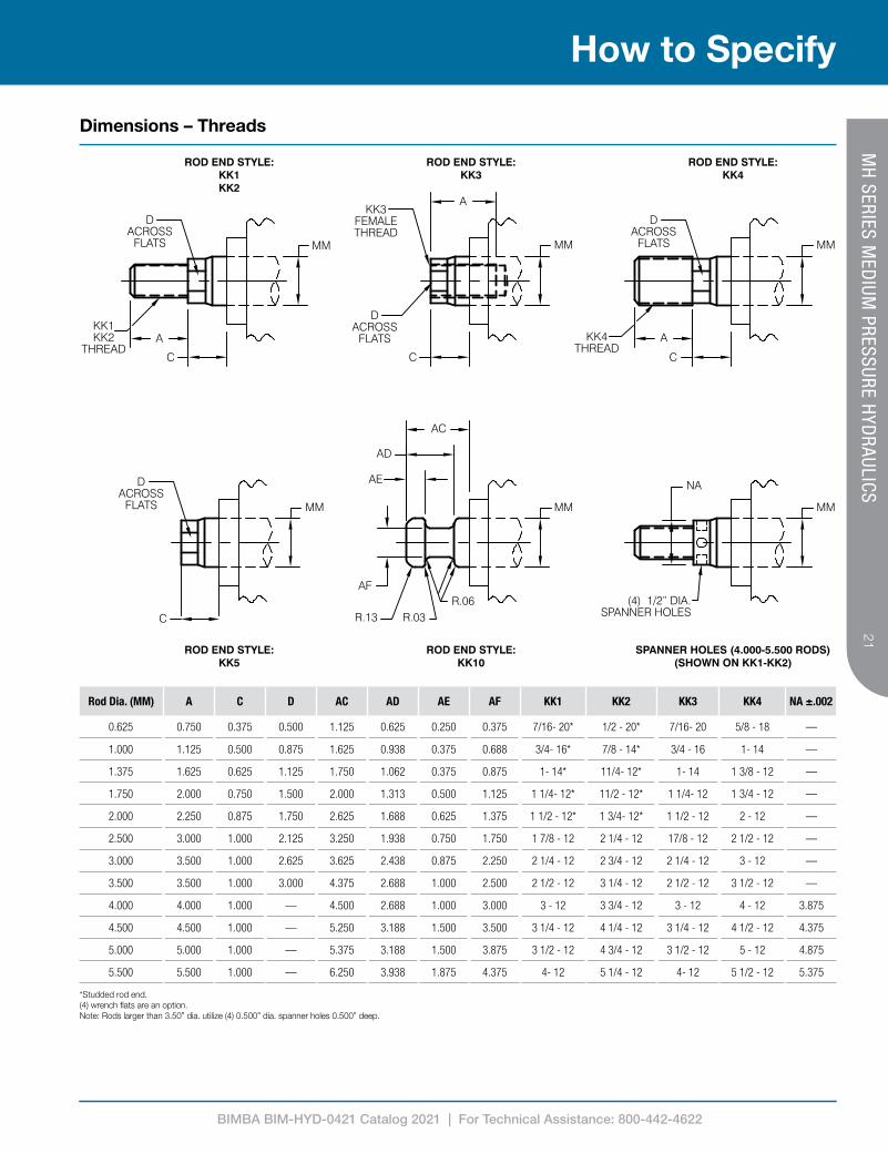
Dimensions – Threads
Rod Dia. (MM) A C D AC AD AE AF KK1 KK2 KK3 KK4 NA ±.002
0.625 0.750 0.375 0.500 1.125 0.625 0.250 0.375 7/16- 20* 1/2 - 20* 7/16- 20 5/8 - 18 —
1.000 1.125 0.500 0.875 1.625 0.938 0.375 0.688 3/4- 16* 7/8 - 14* 3/4 - 16 1- 14 —
1.375 1.625 0.625 1.125 1.750 1.062 0.375 0.875 1- 14* 11/4- 12* 1- 14 1 3/8 - 12 —
1.750 2.000 0.750 1.500 2.000 1.313 0.500 1.125 1 1/4- 12* 11/2 - 12* 1 1/4- 12 1 3/4 - 12 —
2.000 2.250 0.875 1.750 2.625 1.688 0.625 1.375 1 1/2 - 12* 1 3/4- 12* 1 1/2 - 12 2 - 12 —
2.500 3.000 1.000 2.125 3.250 1.938 0.750 1.750 1 7/8 - 12 2 1/4 - 12 17/8 - 12 2 1/2 - 12 —
3.000 3.500 1.000 2.625 3.625 2.438 0.875 2.250 2 1/4 - 12 2 3/4 - 12 2 1/4 - 12 3 - 12 —
3.500 3.500 1.000 3.000 4.375 2.688 1.000 2.500 2 1/2 - 12 3 1/4 - 12 2 1/2 - 12 3 1/2 - 12 —
4.000 4.000 1.000 — 4.500 2.688 1.000 3.000 3 - 12 3 3/4 - 12 3 - 12 4 - 12 3.875
4.500 4.500 1.000 — 5.250 3.188 1.500 3.500 3 1/4 - 12 4 1/4 - 12 3 1/4 - 12 4 1/2 - 12 4.375
5.000 5.000 1.000 — 5.375 3.188 1.500 3.875 3 1/2 - 12 4 3/4 - 12 3 1/2 - 12 5 - 12 4.875
5.500 5.500 1.000 — 6.250 3.938 1.875 4.375 4- 12 5 1/4 - 12 4- 12 5 1/2 - 12 5.375
*Studded rod end.(4) wrench flats are an option.Note: Rods larger than 3.50” dia. utilize (4) 0.500” dia. spanner holes 0.500” deep.
BIMBA BIM-HYD-0421 Catalog 2021 | For Technical Assistance: 800-442-4622
22
How to Specify
MH
SERIES MED
IUM PRESSURE H
YDRAULICS
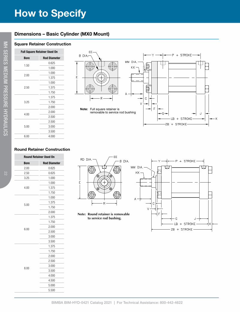
Dimensions – Basic Cylinder (MX0 Mount)
Note: Round retainer is removable to service rod bushing.
Full Square Retainer Used On
Bore Rod Diameter
1.500.625
1.000
2.001.000
1.375
2.50
1.000
1.375
1.750
3.25
1.375
1.750
2.000
4.002.000
2.500
5.00
2.500
3.000
3.500
6.00 4.000
Round Retainer Used On
Bore Rod Diameter
2.00 0.625
2.50 0.625
3.25 1.000
4.00
1.000
1.375
1.750
5.00
1.000
1.375
1.750
2.000
6.00
1.375
1.750
2.000
2.500
3.000
3.500
8.00
1.375
1.750
2.000
2.500
3.000
3.500
4.000
4.500
5.000
5.500
Square Retainer Construction
Round Retainer Construction

BIMBA BIM-HYD-0421 Catalog 2021 | For Technical Assistance: 800-442-4622
2323
How to SpecifyM
H SERIES M
EDIUM
PRESSURE HYD
RAULICS
Dimensions – Basic Cylinder (MX0 Mount)
1. Max single acting pressure rating (non-shock). Any additional opposed intensified pressure related to varying impact area within the cylinder is not taken into consideration (ram cylinders).
2. B dimension tolerance is +.000 / -.0023. Where SQ is shown in chart, cylinder utilizes a full square retainer.
BoreRod Dia.
(MM)
MaxPSI
Rating1E A B2 C
EEF G J K KK R RD3 V Y
Add to Stroke
NPTF SAE LB P ZB
1.500.625 1500
2.0000.750 1.124 0.375
3/8 #6 0.375 1.500 1.000 0.250
See
rod
end
deta
il cha
rt on
pag
e 21
1.430SQ 0.250 1.875
3.625 2.3754.875
1.000 1500 1.125 1.499 0.500 SQ 0.500 2.250 5.250
2.00
0.625 1500
2.500
0.750 1.124 0.375
3/8 #6 0.375 1.500 1.000 0.313 1.840
2.000 0.250 1.875
3.625 2.375
4.938
1.000 1500 1.125 1.499 0.500 SQ 0.500 2.250 5.313
1.375 1500 1.625 1.999 0.625 SQ 0.625 2.500 5.563
2.50
0.625 1000
3.000
0.750 1.124 0.375
3/8 #6 0.375 1.500 1.000 0.313 2.190
2.000 0.250 1.875
3.750 2.500
5.063
1.000 1500 1.125 1.499 0.500 SQ 0.500 2.250 5.438
1.375 1500 1.625 1.999 0.625 SQ 0.625 2.500 5.688
1.750 1500 2.000 2.374 0.750 SQ 0.750 2.750 5.938
3.25
1.000 1500
3.750
1.125 1.499 0.500
1/2 #10 0.625 1.750 1.250 0.375 2.760
2.750 0.250 2.375
4.250 2.750
6.000
1.375 1500 1.625 1.999 0.625 SQ 0.375 2.625 6.250
1.750 1500 2.000 2.374 0.750 SQ 0.500 2.875 6.500
2.000 1500 2.250 2.624 0.875 SQ 0.500 3.000 6.625
4.00
1.000 1000
4.500
1.125 1.499 0.500
1/2 #10 0.625 1.750 1.250 0.375 3.320
2.750 0.250 2.375
4.250 2.750
6.000
1.375 1000 1.625 1.999 0.625 3.500 0.375 2.625 6.250
1.750 1000 2.000 2.374 0.750 3.500 0.500 2.875 6.500
2.000 1000 2.250 2.624 0.875 SQ 0.500 3.000 6.625
2.500 1000 3.000 3.124 1.000 SQ 0.625 3.250 6.875
5.00
1.000 750
5.500
1.125 1.499 0.500
1/2 #10 0.625 1.750 1.250 0.438 4.100
2.750 0.250 2.375
4.500 3.000
6.313
1.375 1000 1.625 1.999 0.625 3.500 0.375 2.625 6.563
1.750 1000 2.000 2.374 0.750 3.500 0.500 2.875 6.813
2.000 1000 2.250 2.624 0.875 4.250 0.500 3.000 6.983
2.500 1000 3.000 3.124 1.000 SQ 0.625 3.250 7.188
3.000 1000 3.500 3.749 1.000 SQ 0.625 3.250 7.188
3.500 1000 3.500 4.249 1.000 SQ 0.625 3.250 7.188
6.00
1.375 750
6.500
1.625 1.999 0.625
3/4 #12 0.750 2.000 1.500 0.438 4.880
3.500 0.250 2.750
5.000 3.250
7.063
1.750 750 2.000 2.374 0.750 3.875 0.375 3.000 7.313
2.000 750 2.250 2.624 0.875 4.250 0.375 3.125 7.438
2.500 750 3.000 3.124 1.000 4.625 0.500 3.375 7.688
3.000 750 3.500 3.749 1.000 5.250 0.500 3.375 7.688
3.500 750 3.500 4.249 1.000 5.750 0.500 3.375 7.688
4.000 750 4.000 4.749 1.000 SQ 0.500 3.375 7.688
8.00
1.375 500
8.500
1.625 1.999 0.625
3/4 #12 0.750 2.000 1.500 0.563 6.440
3.500 0.250 2.750
5.125 3.375
7.313
1.750 500 2.000 2.374 0.750 3.875 0.375 3.000 7.563
2.000 675 2.250 2.624 0.875 4.250 0.375 3.125 7.688
2.500 675 3.000 3.124 1.000 4.625 0.500 3.375 7.938
3.000 675 3.500 3.749 1.000 5.250 0.500 3.375 7.938
3.500 675 3.500 4.249 1.000 5.750 0.500 3.375 7.938
4.000 675 4.000 4.749 1.000 6.500 0.500 3.375 7.938
4.500 675 4.500 5.249 1.000 7.250 0.500 3.375 7.938
5.000 675 5.000 5.749 1.000 7.500 0.500 3.375 7.938
5.500 675 5.500 6.249 1.000 7.500 0.500 3.375 7.938

BIMBA BIM-HYD-0421 Catalog 2021 | For Technical Assistance: 800-442-4622
24
How to Specify
Dimensions – Trunnion Mounts
MH
SERIES MED
IUM PRESSURE H
YDRAULICS
MT1: Head Trunnion
MT2: Cap Trunnion
MT4: Intermediate Trunnion

BIMBA BIM-HYD-0421 Catalog 2021 | For Technical Assistance: 800-442-4622
2525
How to Specify
Dimensions – Trunnion Mounts
MH
SERIES MED
IUM PRESSURE H
YDRAULICS
Bore Rod Dia. (MM)
Max PSI Rating¹ E BD TD² TL TM UM UT UV XG XI³ MT4
Min Stroke
Add to Stroke
XJ ZB
1.500.625 1500
2.000 1.250 1.000 1.000 2.500 4.500 4.000 2.5001.750 3.250
0.3754.125 4.875
1.000 1500 2.125 3.625 4.500 5.250
2.00
0.625 1500
2.500 1.500 1.000 1.000 3.000 5.000 4.500 3.000
1.750 3.375
0.625
4.125 4.938
1.000 1500 2.125 3.750 4.500 5.313
1.375 1500 2.375 4.000 4.750 5.563
2.50
0.625 1000
3.000 1.500 1.000 1.000 3.500 5.500 5.000 3.500
1.750 3.375
0.500
4.250 5.063
1.000 1500 2.125 3.750 4.625 5.438
1.375 1500 2.375 4.000 4.875 5.688
1.750 1500 2.625 4.250 5.125 5.938
3.25
1.000 1500
3.750 2.000 1.000 1.000 4.500 6.500 5.750 4.250
2.250 4.250
1.000
5.000 6.000
1.375 1500 2.500 4.500 5.250 6.250
1.750 1500 2.750 4.750 5.500 6.500
2.000 1500 2.875 4.875 5.625 6.625
4.00
1.000 1000
4.500 2.000 1.000 1.000 5.250 7.250 6.500 5.000
2.250 4.250
1.000
5.000 6.000
1.375 1000 2.500 4.500 5.250 6.250
1.750 1000 2.750 4.750 5.500 6.500
2.000 1000 2.875 4.875 5.625 6.625
2.500 1000 3.125 5.125 5.875 6.875
5.00
1.000 750
5.500 2.000 1.000 1.000 6.250 8.250 7.500 6.000
2.250 4.250
0.750
5.250 6.313
1.375 1000 2.500 4.500 5.500 6.563
1.750 1000 2.750 4.750 5.750 6.813
2.000 1000 2.875 4.875 5.875 6.938
2.500 1000 3.125 5.125 6.125 7.188
3.000 1000 3.125 5.125 6.125 7.188
3.500 1000 3.125 5.125 6.125 7.188
6.00
1.375 750
6.500 2.000 1.375 1.375 7.625 10.375 9.250 7.000
2.625 4.750
0.750
5.875 7.063
1.750 750 2.875 5.000 6.125 7.313
2.000 750 3.000 5.125 6.250 7.438
2.500 750 3.250 5.375 6.500 7.688
3.000 750 3.250 5.375 6.500 7.688
3.500 750 3.250 5.375 6.500 7.688
4.000 750 3.250 5.375 6.500 7.688
8.00
1.375 500
8.500 2.500 1.375 1.375 9.750 12.500 11.250 9.500
2.625 5.000
1.125
6.000 7.313
1.750 500 2.875 5.250 6.250 7.563
2.000 675 3.000 5.375 6.375 7.688
2.500 675 3.250 5.625 6.625 7.938
3.000 675 3.250 5.625 6.625 7.938
3.500 675 3.250 5.625 6.625 7.938
4.000 675 3.250 5.625 6.625 7.938
4.500 675 3.250 5.625 6.625 7.938
5.000 675 3.250 5.625 6.625 7.938
5.500 675 3.250 5.625 6.625 7.938
1. Max single acting pressure rating (non-shock). Any additional opposed intensified pressure related to varying impact area within the cylinder is not taken into consideration (ram cylinders).2. TD dimension tolerance is + .000 / - .001
3. XI dimension is the minimum that can be supplied and leaves 1/4” gap between head & trunnion block (customer to specify XI dimension).
BIMBA BIM-HYD-0421 Catalog 2021 | For Technical Assistance: 800-442-4622
26
How to Specify
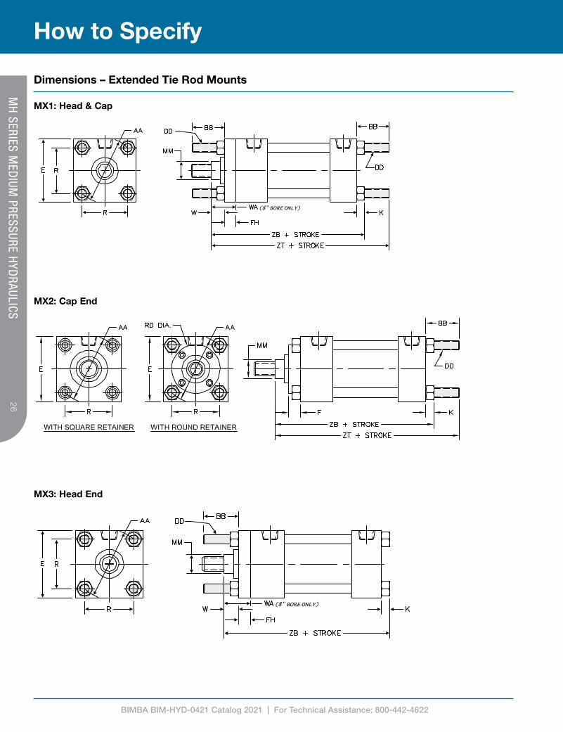
Dimensions – Extended Tie Rod Mounts
MH
SERIES MED
IUM PRESSURE H
YDRAULICS
MX1: Head & Cap
MX2: Cap End
MX3: Head End
BIMBA BIM-HYD-0421 Catalog 2021 | For Technical Assistance: 800-442-4622
2727
How to Specify
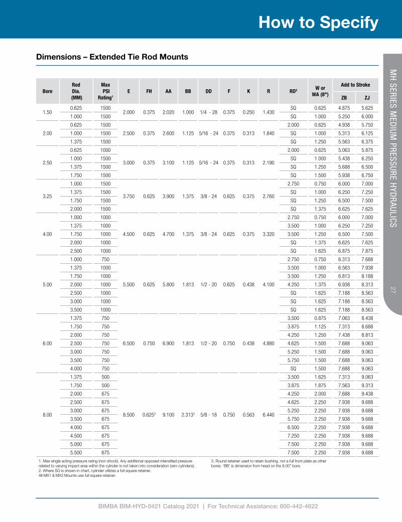
Dimensions – Extended Tie Rod Mounts
MH
SERIES MED
IUM PRESSURE H
YDRAULICS
1. Max single acting pressure rating (non-shock). Any additional opposed intensified pressure related to varying impact area within the cylinder is not taken into consideration (ram cylinders).2. Where SQ is shown in chart, cylinder utilizes a full square retainer. All MX1 & MX3 Mounts use full square retainer.
3. Round retainer used to retain bushing, not a full front plate as other bores. ‘BB’ is dimension from head on the 8.00” bore.
BoreRod Dia.
(MM)
Max PSI
Rating1
E FH AA BB DD F K R RD2 W or WA (8")
Add to Stroke
ZB ZJ
1.500.625 1500
2.000 0.375 2.020 1.000 1/4 - 28 0.375 0.250 1.430SQ 0.625 4.875 5.625
1.000 1500 SQ 1.000 5.250 6.000
2.00
0.625 1500
2.500 0.375 2.600 1.125 5/16 - 24 0.375 0.313 1.840
2.000 0.625 4.938 5.750
1.000 1500 SQ 1.000 5.313 6.125
1.375 1500 SQ 1.250 5.563 6.375
2.50
0.625 1000
3.000 0.375 3.100 1.125 5/16 - 24 0.375 0.313 2.190
2.000 0.625 5.063 5.875
1.000 1500 SQ 1.000 5.438 6.250
1.375 1500 SQ 1.250 5.688 6.500
1.750 1500 SQ 1.500 5.938 6.750
3.25
1.000 1500
3.750 0.625 3.900 1.375 3/8 - 24 0.625 0.375 2.760
2.750 0.750 6.000 7.000
1.375 1500 SQ 1.000 6.250 7.250
1.750 1500 SQ 1.250 6.500 7.500
2.000 1500 SQ 1.375 6.625 7.625
4.00
1.000 1000
4.500 0.625 4.700 1.375 3/8 - 24 0.625 0.375 3.320
2.750 0.750 6.000 7.000
1.375 1000 3.500 1.000 6.250 7.250
1.750 1000 3.500 1.250 6.500 7.500
2.000 1000 SQ 1.375 6.625 7.625
2.500 1000 SQ 1.625 6.875 7.875
5.00
1.000 750
5.500 0.625 5.800 1.813 1/2 - 20 0.625 0.438 4.100
2.750 0.750 6.313 7.688
1.375 1000 3.500 1.000 6.563 7.938
1.750 1000 3.500 1.250 6.813 8.188
2.000 1000 4.250 1.375 6.938 8.313
2.500 1000 SQ 1.625 7.188 8.563
3.000 1000 SQ 1.625 7.188 8.563
3.500 1000 SQ 1.625 7.188 8.563
6.00
1.375 750
6.500 0.750 6.900 1.813 1/2 - 20 0.750 0.438 4.880
3.500 0.875 7.063 8.438
1.750 750 3.875 1.125 7.313 8.688
2.000 750 4.250 1.250 7.438 8.813
2.500 750 4.625 1.500 7.688 9.063
3.000 750 5.250 1.500 7.688 9.063
3.500 750 5.750 1.500 7.688 9.063
4.000 750 SQ 1.500 7.688 9.063
8.00
1.375 500
8.500 0.6253 9.100 2.3133 5/8 - 18 0.750 0.563 6.440
3.500 1.625 7.313 9.063
1.750 500 3.875 1.875 7.563 9.313
2.000 675 4.250 2.000 7.688 9.438
2.500 675 4.625 2.250 7.938 9.688
3.000 675 5.250 2.250 7.938 9.688
3.500 675 5.750 2.250 7.938 9.688
4.000 675 6.500 2.250 7.938 9.688
4.500 675 7.250 2.250 7.938 9.688
5.000 675 7.500 2.250 7.938 9.688
5.500 675 7.500 2.250 7.938 9.688
BIMBA BIM-HYD-0421 Catalog 2021 | For Technical Assistance: 800-442-4622
28
How to Specify
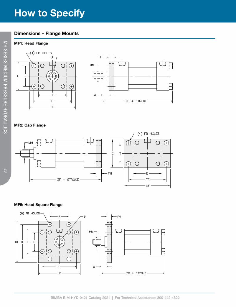
Dimensions – Flange Mounts
MH
SERIES MED
IUM PRESSURE H
YDRAULICS
MF1: Head Flange
MF2: Cap Flange
MF5: Head Square Flange
BIMBA BIM-HYD-0421 Catalog 2021 | For Technical Assistance: 800-442-4622
2929
How to Specify
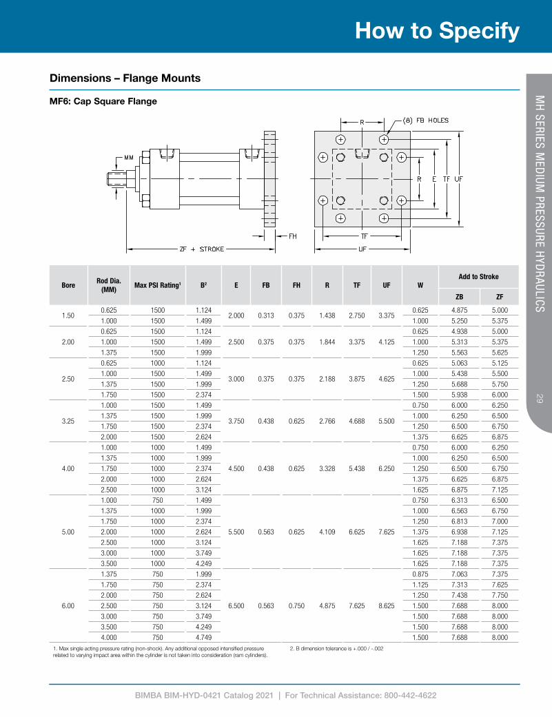
BoreRod Dia.
(MM)Max PSI Rating1 B2 E FB FH R TF UF W
Add to Stroke
ZB ZF
1.500.625 1500 1.124
2.000 0.313 0.375 1.438 2.750 3.3750.625 4.875 5.000
1.000 1500 1.499 1.000 5.250 5.375
2.00
0.625 1500 1.124
2.500 0.375 0.375 1.844 3.375 4.125
0.625 4.938 5.000
1.000 1500 1.499 1.000 5.313 5.375
1.375 1500 1.999 1.250 5.563 5.625
2.50
0.625 1000 1.124
3.000 0.375 0.375 2.188 3.875 4.625
0.625 5.063 5.125
1.000 1500 1.499 1.000 5.438 5.500
1.375 1500 1.999 1.250 5.688 5.750
1.750 1500 2.374 1.500 5.938 6.000
3.25
1.000 1500 1.499
3.750 0.438 0.625 2.766 4.688 5.500
0.750 6.000 6.250
1.375 1500 1.999 1.000 6.250 6.500
1.750 1500 2.374 1.250 6.500 6.750
2.000 1500 2.624 1.375 6.625 6.875
4.00
1.000 1000 1.499
4.500 0.438 0.625 3.328 5.438 6.250
0.750 6.000 6.250
1.375 1000 1.999 1.000 6.250 6.500
1.750 1000 2.374 1.250 6.500 6.750
2.000 1000 2.624 1.375 6.625 6.875
2.500 1000 3.124 1.625 6.875 7.125
5.00
1.000 750 1.499
5.500 0.563 0.625 4.109 6.625 7.625
0.750 6.313 6.500
1.375 1000 1.999 1.000 6.563 6.750
1.750 1000 2.374 1.250 6.813 7.000
2.000 1000 2.624 1.375 6.938 7.125
2.500 1000 3.124 1.625 7.188 7.375
3.000 1000 3.749 1.625 7.188 7.375
3.500 1000 4.249 1.625 7.188 7.375
6.00
1.375 750 1.999
6.500 0.563 0.750 4.875 7.625 8.625
0.875 7.063 7.375
1.750 750 2.374 1.125 7.313 7.625
2.000 750 2.624 1.250 7.438 7.750
2.500 750 3.124 1.500 7.688 8.000
3.000 750 3.749 1.500 7.688 8.000
3.500 750 4.249 1.500 7.688 8.000
4.000 750 4.749 1.500 7.688 8.000
1. Max single acting pressure rating (non-shock). Any additional opposed intensified pressure related to varying impact area within the cylinder is not taken into consideration (ram cylinders).
2. B dimension tolerance is +.000 / -.002
Dimensions – Flange Mounts
MH
SERIES MED
IUM PRESSURE H
YDRAULICS
MF6: Cap Square Flange
BIMBA BIM-HYD-0421 Catalog 2021 | For Technical Assistance: 800-442-4622
30
How to Specify
Dimensions – Flange Mounts
MH
SERIES MED
IUM PRESSURE H
YDRAULICS
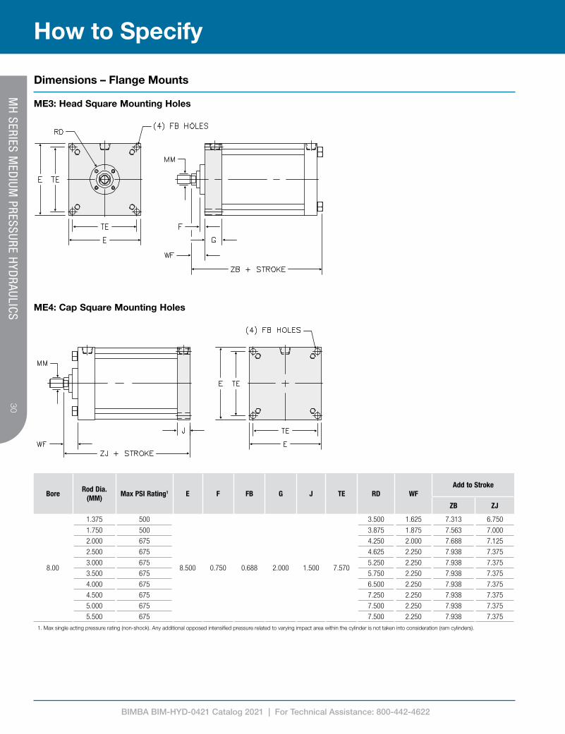
ME3: Head Square Mounting Holes
ME4: Cap Square Mounting Holes
1. Max single acting pressure rating (non-shock). Any additional opposed intensified pressure related to varying impact area within the cylinder is not taken into consideration (ram cylinders).
BoreRod Dia.
(MM)Max PSI Rating1 E F FB G J TE RD WF
Add to Stroke
ZB ZJ
8.00
1.375 500
8.500 0.750 0.688 2.000 1.500 7.570
3.500 1.625 7.313 6.750
1.750 500 3.875 1.875 7.563 7.000
2.000 675 4.250 2.000 7.688 7.125
2.500 675 4.625 2.250 7.938 7.375
3.000 675 5.250 2.250 7.938 7.375
3.500 675 5.750 2.250 7.938 7.375
4.000 675 6.500 2.250 7.938 7.375
4.500 675 7.250 2.250 7.938 7.375
5.000 675 7.500 2.250 7.938 7.375
5.500 675 7.500 2.250 7.938 7.375
BIMBA BIM-HYD-0421 Catalog 2021 | For Technical Assistance: 800-442-4622
3131
How to SpecifyM
H SERIES M
EDIUM
PRESSURE HYD
RAULICS
Dimensions – Spherical Bearing Mount
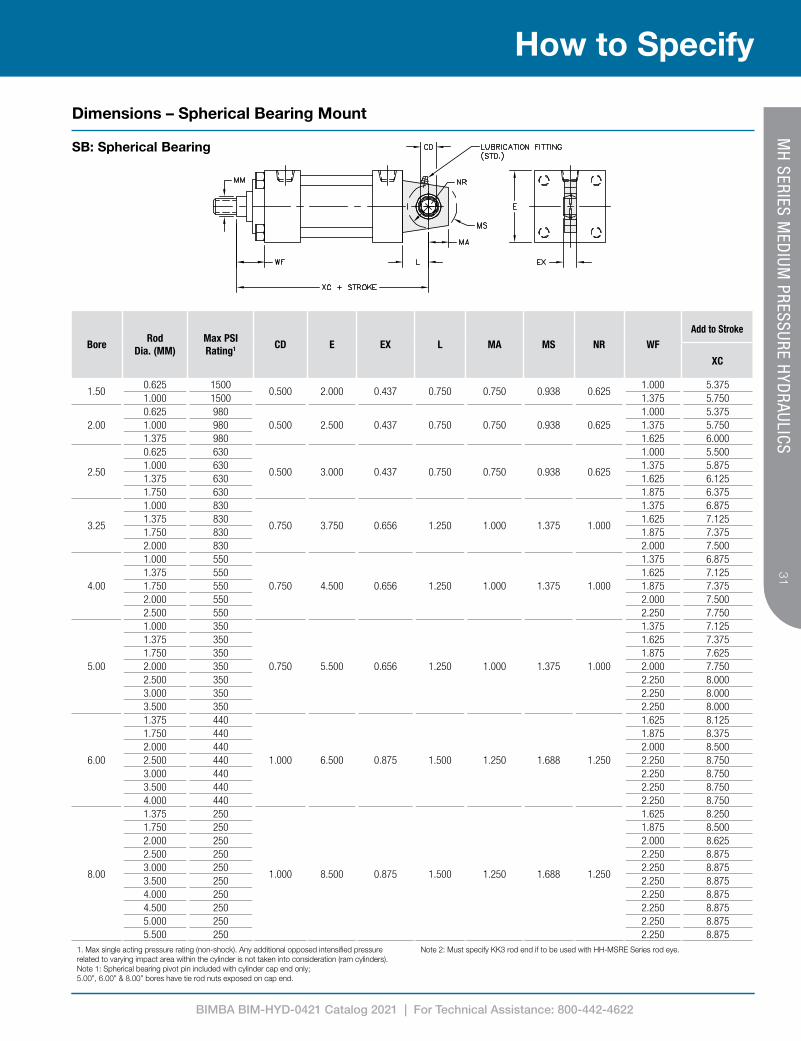
SB: Spherical Bearing
1. Max single acting pressure rating (non-shock). Any additional opposed intensified pressure related to varying impact area within the cylinder is not taken into consideration (ram cylinders).Note 1: Spherical bearing pivot pin included with cylinder cap end only; 5.00”, 6.00” & 8.00” bores have tie rod nuts exposed on cap end.
Note 2: Must specify KK3 rod end if to be used with HH-MSRE Series rod eye.
BoreRod
Dia. (MM)Max PSI Rating1 CD E EX L MA MS NR WF
Add to Stroke
XC
1.500.625 1500
0.500 2.000 0.437 0.750 0.750 0.938 0.6251.000 5.375
1.000 1500 1.375 5.750
2.000.625 980
0.500 2.500 0.437 0.750 0.750 0.938 0.6251.000 5.375
1.000 980 1.375 5.7501.375 980 1.625 6.000
2.50
0.625 630
0.500 3.000 0.437 0.750 0.750 0.938 0.625
1.000 5.5001.000 630 1.375 5.8751.375 630 1.625 6.1251.750 630 1.875 6.375
3.25
1.000 830
0.750 3.750 0.656 1.250 1.000 1.375 1.000
1.375 6.8751.375 830 1.625 7.1251.750 830 1.875 7.3752.000 830 2.000 7.500
4.00
1.000 550
0.750 4.500 0.656 1.250 1.000 1.375 1.000
1.375 6.8751.375 550 1.625 7.1251.750 550 1.875 7.3752.000 550 2.000 7.5002.500 550 2.250 7.750
5.00
1.000 350
0.750 5.500 0.656 1.250 1.000 1.375 1.000
1.375 7.1251.375 350 1.625 7.3751.750 350 1.875 7.6252.000 350 2.000 7.7502.500 350 2.250 8.0003.000 350 2.250 8.0003.500 350 2.250 8.000
6.00
1.375 440
1.000 6.500 0.875 1.500 1.250 1.688 1.250
1.625 8.1251.750 440 1.875 8.3752.000 440 2.000 8.5002.500 440 2.250 8.7503.000 440 2.250 8.7503.500 440 2.250 8.7504.000 440 2.250 8.750
8.00
1.375 250
1.000 8.500 0.875 1.500 1.250 1.688 1.250
1.625 8.2501.750 250 1.875 8.5002.000 250 2.000 8.6252.500 250 2.250 8.8753.000 250 2.250 8.8753.500 250 2.250 8.8754.000 250 2.250 8.8754.500 250 2.250 8.8755.000 250 2.250 8.8755.500 250 2.250 8.875
BIMBA BIM-HYD-0421 Catalog 2021 | For Technical Assistance: 800-442-4622
32
How to Specify
MH
SERIES MED
IUM PRESSURE H
YDRAULICS
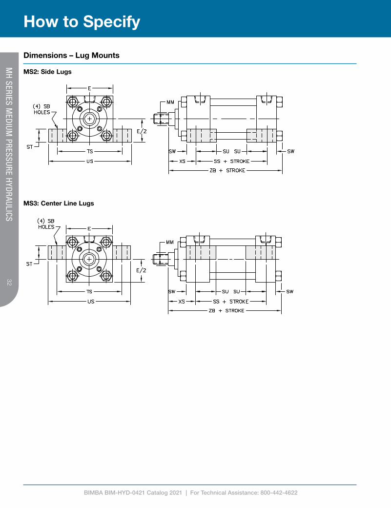
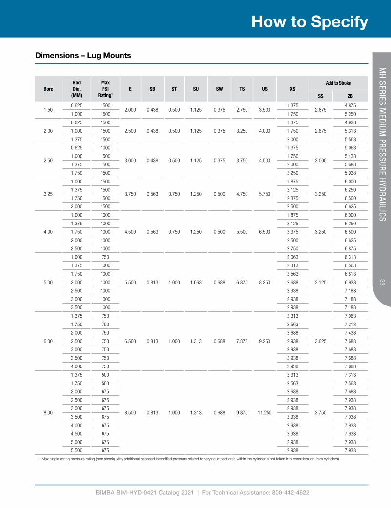
Dimensions – Lug Mounts
MS2: Side Lugs
MS3: Center Line Lugs
BIMBA BIM-HYD-0421 Catalog 2021 | For Technical Assistance: 800-442-4622
3333
How to SpecifyM
H SERIES M
EDIUM
PRESSURE HYD
RAULICS
Dimensions – Lug Mounts
BoreRod Dia.
(MM)
Max PSI
Rating1
E SB ST SU SW TS US XSAdd to Stroke
SS ZB
1.500.625 1500
2.000 0.438 0.500 1.125 0.375 2.750 3.5001.375
2.8754.875
1.000 1500 1.750 5.250
2.00
0.625 1500
2.500 0.438 0.500 1.125 0.375 3.250 4.000
1.375
2.875
4.938
1.000 1500 1.750 5.313
1.375 1500 2.000 5.563
2.50
0.625 1000
3.000 0.438 0.500 1.125 0.375 3.750 4.500
1.375
3.000
5.063
1.000 1500 1.750 5.438
1.375 1500 2.000 5.688
1.750 1500 2.250 5.938
3.25
1.000 1500
3.750 0.563 0.750 1.250 0.500 4.750 5.750
1.875
3.250
6.000
1.375 1500 2.125 6.250
1.750 1500 2.375 6.500
2.000 1500 2.500 6.625
4.00
1.000 1000
4.500 0.563 0.750 1.250 0.500 5.500 6.500
1.875
3.250
6.000
1.375 1000 2.125 6.250
1.750 1000 2.375 6.500
2.000 1000 2.500 6.625
2.500 1000 2.750 6.875
5.00
1.000 750
5.500 0.813 1.000 1.063 0.688 6.875 8.250
2.063
3.125
6.313
1.375 1000 2.313 6.563
1.750 1000 2.563 6.813
2.000 1000 2.688 6.938
2.500 1000 2.938 7.188
3.000 1000 2.938 7.188
3.500 1000 2.938 7.188
6.00
1.375 750
6.500 0.813 1.000 1.313 0.688 7.875 9.250
2.313
3.625
7.063
1.750 750 2.563 7.313
2.000 750 2.688 7.438
2.500 750 2.938 7.688
3.000 750 2.938 7.688
3.500 750 2.938 7.688
4.000 750 2.938 7.688
8.00
1.375 500
8.500 0.813 1.000 1.313 0.688 9.875 11.250
2.313
3.750
7.313
1.750 500 2.563 7.563
2.000 675 2.688 7.688
2.500 675 2.938 7.938
3.000 675 2.938 7.938
3.500 675 2.938 7.938
4.000 675 2.938 7.938
4.500 675 2.938 7.938
5.000 675 2.938 7.938
5.500 675 2.938 7.938
1. Max single acting pressure rating (non-shock). Any additional opposed intensified pressure related to varying impact area within the cylinder is not taken into consideration (ram cylinders).
BIMBA BIM-HYD-0421 Catalog 2021 | For Technical Assistance: 800-442-4622
34
How to Specify
MH
SERIES MED
IUM PRESSURE H
YDRAULICS
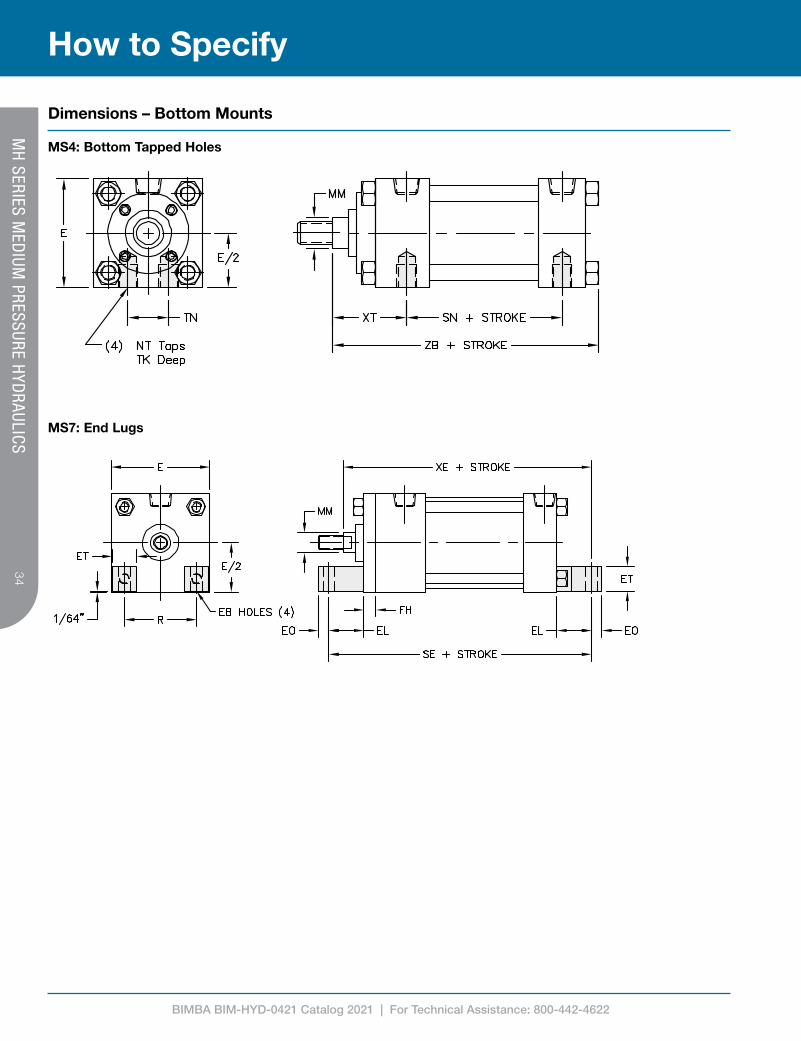
Dimensions – Bottom Mounts
MS4: Bottom Tapped Holes
MS7: End Lugs
BIMBA BIM-HYD-0421 Catalog 2021 | For Technical Assistance: 800-442-4622
3535
How to SpecifyM
H SERIES M
EDIUM
PRESSURE HYD
RAULICS
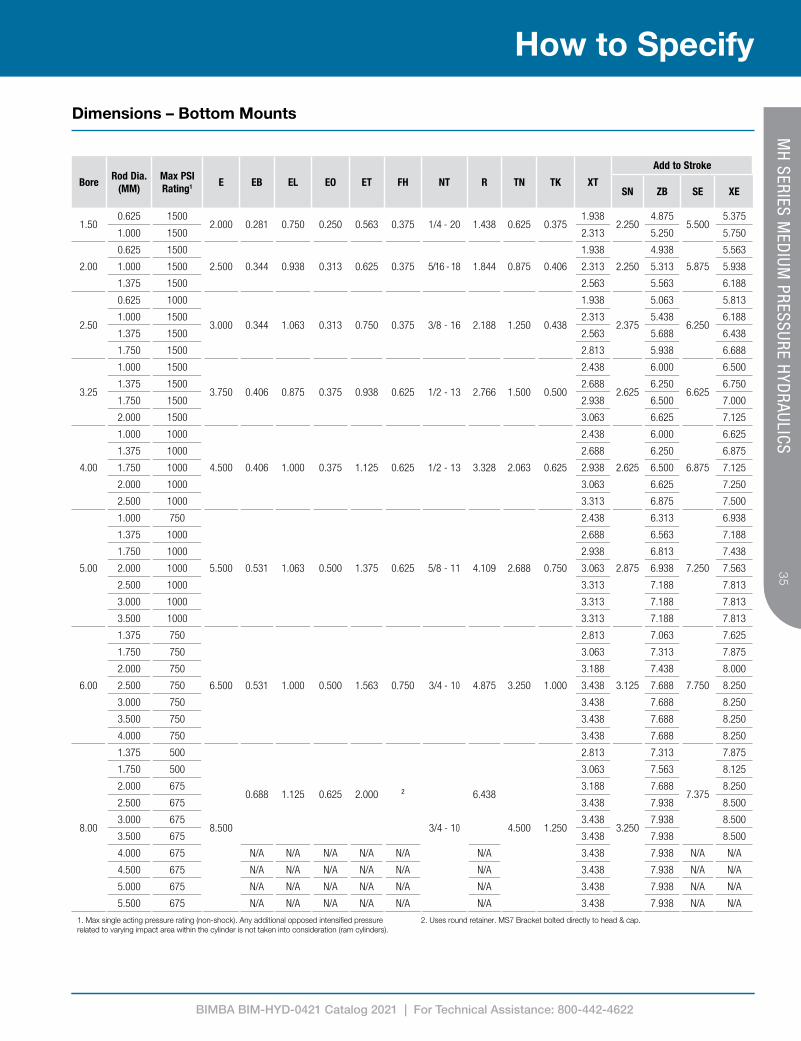
Dimensions – Bottom Mounts
1. Max single acting pressure rating (non-shock). Any additional opposed intensified pressure related to varying impact area within the cylinder is not taken into consideration (ram cylinders).
2. Uses round retainer. MS7 Bracket bolted directly to head & cap.
BoreRod Dia.
(MM)Max PSI Rating1 E EB EL EO ET FH NT R TN TK XT
Add to Stroke
SN ZB SE XE
1.500.625 1500
2.000 0.281 0.750 0.250 0.563 0.375 1/4 - 20 1.438 0.625 0.3751.938
2.2504.875
5.5005.375
1.000 1500 2.313 5.250 5.750
2.00
0.625 1500
2.500 0.344 0.938 0.313 0.625 0.375 5/16 - 18 1.844 0.875 0.406
1.938
2.250
4.938
5.875
5.563
1.000 1500 2.313 5.313 5.938
1.375 1500 2.563 5.563 6.188
2.50
0.625 1000
3.000 0.344 1.063 0.313 0.750 0.375 3/8 - 16 2.188 1.250 0.438
1.938
2.375
5.063
6.250
5.813
1.000 1500 2.313 5.438 6.188
1.375 1500 2.563 5.688 6.438
1.750 1500 2.813 5.938 6.688
3.25
1.000 1500
3.750 0.406 0.875 0.375 0.938 0.625 1/2 - 13 2.766 1.500 0.500
2.438
2.625
6.000
6.625
6.500
1.375 1500 2.688 6.250 6.750
1.750 1500 2.938 6.500 7.000
2.000 1500 3.063 6.625 7.125
4.00
1.000 1000
4.500 0.406 1.000 0.375 1.125 0.625 1/2 - 13 3.328 2.063 0.625
2.438
2.625
6.000
6.875
6.625
1.375 1000 2.688 6.250 6.875
1.750 1000 2.938 6.500 7.125
2.000 1000 3.063 6.625 7.250
2.500 1000 3.313 6.875 7.500
5.00
1.000 750
5.500 0.531 1.063 0.500 1.375 0.625 5/8 - 11 4.109 2.688 0.750
2.438
2.875
6.313
7.250
6.938
1.375 1000 2.688 6.563 7.188
1.750 1000 2.938 6.813 7.438
2.000 1000 3.063 6.938 7.563
2.500 1000 3.313 7.188 7.813
3.000 1000 3.313 7.188 7.813
3.500 1000 3.313 7.188 7.813
6.00
1.375 750
6.500 0.531 1.000 0.500 1.563 0.750 3/4 - 10 4.875 3.250 1.000
2.813
3.125
7.063
7.750
7.625
1.750 750 3.063 7.313 7.875
2.000 750 3.188 7.438 8.000
2.500 750 3.438 7.688 8.250
3.000 750 3.438 7.688 8.250
3.500 750 3.438 7.688 8.250
4.000 750 3.438 7.688 8.250
8.00
1.375 500
8.500
0.688 1.125 0.625 2.000 ²
3/4 - 10
6.438
4.500 1.250
2.813
3.250
7.313
7.375
7.875
1.750 500 3.063 7.563 8.125
2.000 675 3.188 7.688 8.250
2.500 675 3.438 7.938 8.500
3.000 675 3.438 7.938 8.500
3.500 675 3.438 7.938 8.500
4.000 675 N/A N/A N/A N/A N/A N/A 3.438 7.938 N/A N/A
4.500 675 N/A N/A N/A N/A N/A N/A 3.438 7.938 N/A N/A
5.000 675 N/A N/A N/A N/A N/A N/A 3.438 7.938 N/A N/A
5.500 675 N/A N/A N/A N/A N/A N/A 3.438 7.938 N/A N/A
BIMBA BIM-HYD-0421 Catalog 2021 | For Technical Assistance: 800-442-4622
36
How to Specify
1. Max single acting pressure rating (non-shock). Any additional opposed intensified pressure related to varying impact area within the cylinder is not taken into consideration (ram cylinders).
Note: Pivot pin included with cylinder cap end only.
BoreRod Dia.
(MM)Max PSI Rating1 CB CD CW E L LR M MR WF
Add to Stroke
XC
1.500.625 1500
0.750 0.500 0.500 2.000 0.750 0.563 0.500 0.6251.000 5.375
1.000 1500 1.375 5.750
2.000.625 1500
0.750 0.500 0.500 2.500 0.750 0.563 0.500 0.6251.000 5.375
1.000 1500 1.375 5.7501.375 1500 1.625 6.000
2.50
0.625 1000
0.750 0.500 0.500 3.000 0.750 0.563 0.500 0.625
1.000 5.5001.000 1500 1.375 5.8751.375 1500 1.625 6.1251.750 1500 1.875 6.375
3.25
1.000 1500
1.250 0.750 0.625 3.750 1.250 1.000 0.750 0.938
1.375 6.8751.375 1500 1.625 7.1251.750 1500 1.875 7.3752.000 1500 2.000 7.500
4.00
1.000 1000
1.250 0.750 0.625 4.500 1.250 1.000 0.750 0.938
1.375 6.8751.375 1000 1.625 7.1251.750 1000 1.875 7.3752.000 1000 2.000 7.5002.500 1000 2.250 7.750
5.00
1.000 750
1.250 0.750 0.625 5.500 1.250 1.000 0.750 0.938
1.375 7.1251.375 1000 1.625 7.3751.750 1000 1.875 7.6252.000 1000 2.000 7.7502.500 1000 2.250 8.0003.000 1000 2.250 8.0003.500 1000 2.250 8.000
6.00
1.375 750
1.500 1.000 0.750 6.500 1.500 1.250 1.000 1.188
1.625 8.1251.750 750 1.875 8.3752.000 750 2.000 8.5002.500 750 2.250 8.7503.000 750 2.250 8.7503.500 750 2.250 8.7504.000 750 2.250 8.750
8.00
1.375 500
1.500 1.000 0.750 8.500 1.500 1.250 1.000 1.188
1.625 8.2501.750 500 1.875 8.5002.000 675 2.000 8.6252.500 675 2.250 8.8753.000 675 2.250 8.8753.500 675 2.250 8.8754.000 675 2.250 8.8754.500 675 2.250 8.8755.000 675 2.250 8.8755.500 675 2.250 8.875
MH
SERIES MED
IUM PRESSURE H
YDRAULICS
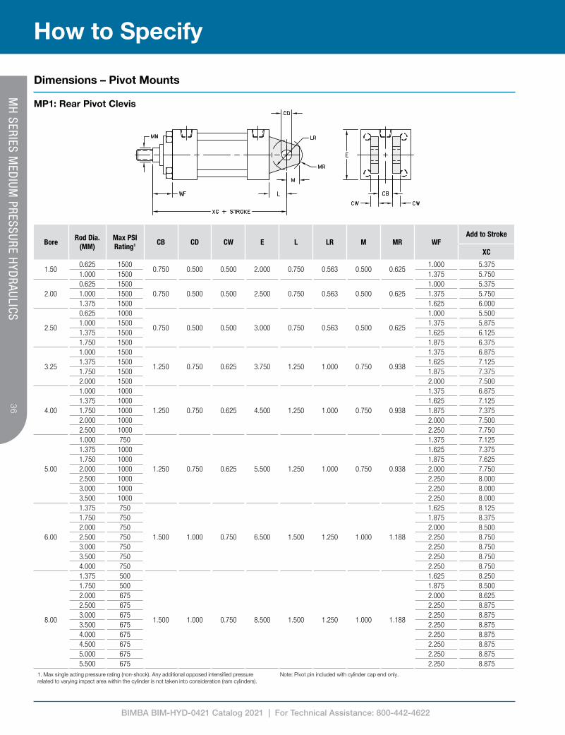
Dimensions – Pivot Mounts
MP1: Rear Pivot Clevis

BIMBA BIM-HYD-0421 Catalog 2021 | For Technical Assistance: 800-442-4622
3737
How to SpecifyM
H SERIES M
EDIUM
PRESSURE HYD
RAULICS
Dimensions – Pivot Mounts
MP2: Rear Pivot Detachable Clevis
1. Max single acting pressure rating (non-shock). Any additional opposed intensified pressure related to varying impact area within the cylinder is not taken into consideration (ram cylinders).
Note: Pivot pin included with cylinder cap end only.
BoreRod Dia.
(MM)Max PSI Rating1 CB CD CW E F L LR M MR WF
Add to Stroke
XD
1.500.625 1500
0.750 0.500 0.500 2.000 0.375 0.750 0.563 0.500 0.6251.000 5.750
1.000 1500 1.375 6.125
2.000.625 1500
0.750 0.500 0.500 2.500 0.375 0.750 0.563 0.500 0.6251.000 5.750
1.000 1500 1.375 6.1251.375 1500 1.625 6.375
2.50
0.625 1000
0.750 0.500 0.500 3.000 0.375 0.750 0.563 0.500 0.625
1.000 5.8751.000 1500 1.375 6.2501.375 1500 1.625 6.5001.750 1500 1.875 6.750
3.25
1.000 1500
1.250 0.750 0.625 3.750 0.625 1.250 1.000 0.750 0.938
1.375 7.5001.375 1500 1.625 7.7501.750 1500 1.875 8.0002.000 1500 2.000 8.125
4.00
1.000 1000
1.250 0.750 0.625 4.500 0.625 1.250 1.000 0.750 0.938
1.375 7.5001.375 1000 1.625 7.7501.750 1000 1.875 8.0002.000 1000 2.000 8.1252.500 1000 2.250 8.375
5.00
1.000 750
1.250 0.750 0.625 5.500 0.625 1.250 1.000 0.750 0.938
1.375 7.7501.375 1000 1.625 8.0001.750 1000 1.875 8.2502.000 1000 2.000 8.3752.500 1000 2.250 8.6253.000 1000 2.250 8.6253.500 1000 2.250 8.625
6.00
1.375 750
1.500 1.000 0.750 6.500 0.750 1.500 1.250 1.000 1.188
1.625 8.8751.750 750 1.875 9.1252.000 750 2.000 9.2502.500 750 2.250 9.5003.000 750 2.250 9.5003.500 750 2.250 9.5004.000 750 2.250 9.500

BIMBA BIM-HYD-0421 Catalog 2021 | For Technical Assistance: 800-442-4622
38
How to Specify
MH
SERIES MED
IUM PRESSURE H
YDRAULICS
Dimensions – Basic Double End (MX0 Mount)
MX0D: No Mount
1. Max single acting pressure rating (non-shock). Any additional opposed intensified pressure related to varying impact area within the cylinder is not taken into consideration (ram cylinders).
2. B dimension tolerance is +.000 / -.0023. Where SQ is shown in chart, cylinder utilizes a full square retainer.
BoreRod Dia.
(MM)
Max PSI Rating1 E A B2 C
EEF G K KK R RD3 V Y
Add to StrokeAdd 2x Stroke
NPTF SAE LD P ZM
1.500.625 1500
2.0000.750 1.124 0.375
3/8 #6 0.375 1.500 0.250
See
rod
end
deta
il cha
rt on
pag
e 21
1.438SQ 0.250 1.875
4.125 2.3756.125
1.000 1500 1.125 1.499 0.500 SQ 0.500 2.250 6.875
2.000.625 1500
2.5000.750 1.124 0.375
3/8 #6 0.375 1.500 0.313 1.8442.000 0.250 1.875
4.125 2.3756.125
1.000 1500 1.125 1.499 0.500 SQ 0.500 2.250 6.8751.375 1500 1.625 1.999 0.625 SQ 0.625 2.500 7.375
2.50
0.625 1000
3.000
0.750 1.124 0.375
3/8 #6 0.375 1.500 0.313 2.188
2.000 0.250 1.875
4.250 2.500
6.2501.000 1500 1.125 1.499 0.500 SQ 0.500 2.250 7.0001.375 1500 1.625 1.999 0.625 SQ 0.625 2.500 7.5001.750 1500 2.000 2.374 0.750 SQ 0.750 2.750 8.000
3.25
1.000 1500
3.750
1.125 1.499 0.500
1/2 #10 0.625 1.750 0.375 2.766
2.750 0.250 2.375
4.750 2.750
7.5001.375 1500 1.625 1.999 0.625 SQ 0.375 2.625 8.0001.750 1500 2.000 2.374 0.750 SQ 0.500 2.875 8.5002.000 1500 2.250 2.624 0.875 SQ 0.500 3.000 8.750
4.00
1.000 1000
4.500
1.125 1.499 0.500
1/2 #10 0.625 1.750 0.375 3.328
2.750 0.250 2.375
4.750 2.750
7.5001.375 1000 1.625 1.999 0.625 3.500 0.375 2.625 8.0001.750 1000 2.000 2.374 0.750 3.500 0.500 2.875 8.5002.000 1000 2.250 2.624 0.875 SQ 0.500 3.000 8.7502.500 1000 3.000 3.124 1.000 SQ 0.625 3.250 9.250
5.00
1.000 750
5.500
1.125 1.499 0.500
1/2 #10 0.625 1.750 0.438 4.109
2.750 0.250 2.375
5.000 3.000
7.7501.375 1000 1.625 1.999 0.625 3.500 0.375 2.625 8.2501.750 1000 2.000 2.374 0.750 3.500 0.500 2.875 8.7502.000 1000 2.250 2.624 0.875 4.250 0.500 3.000 9.0002.500 1000 3.000 3.124 1.000 SQ 0.625 3.250 9.5003.000 1000 3.500 3.749 1.000 SQ 0.625 3.250 9.5003.500 1000 3.500 4.249 1.000 SQ 0.625 3.250 9.500
6.00
1.375 750
6.500
1.625 1.999 0.625
3/4 #12 0.750 2.000 0.438 4.875
3.500 0.250 2.750
5.500 3.250
8.7501.750 750 2.000 2.374 0.750 3.875 0.375 3.000 9.2502.000 750 2.250 2.624 0.875 4.250 0.375 3.125 9.5002.500 750 3.000 3.124 1.000 4.625 0.500 3.375 10.0003.000 750 3.500 3.749 1.000 5.250 0.500 3.375 10.0003.500 750 3.500 4.249 1.000 5.750 0.500 3.375 10.0004.000 750 4.000 4.749 1.000 SQ 0.500 3.375 10.000
8.00
1.375 500
8.500
1.625 1.999 0.625
3/4 #12 0.750 2.000 0.563 6.438
3.500 0.250 2.750
5.625 3.375
8.8751.750 500 2.000 2.374 0.750 3.875 0.375 3.000 9.3752.000 675 2.250 2.624 0.875 4.250 0.375 3.125 9.6252.500 675 3.000 3.124 1.000 4.625 0.500 3.375 10.1253.000 675 3.500 3.749 1.000 5.250 0.500 3.375 10.1253.500 675 3.500 4.249 1.000 5.750 0.500 3.375 10.1254.000 675 4.000 4.749 1.000 6.500 0.500 3.375 10.1254.500 675 4.500 5.249 1.000 7.250 0.500 3.375 10.1255.000 675 5.000 5.749 1.000 7.500 0.500 3.375 10.1255.500 675 5.500 6.249 1.000 7.500 0.500 3.375 10.125
BIMBA BIM-HYD-0421 Catalog 2021 | For Technical Assistance: 800-442-4622
3939
How to SpecifyM
H SERIES M
EDIUM
PRESSURE HYD
RAULICS
Dimensions – Double End Mounts
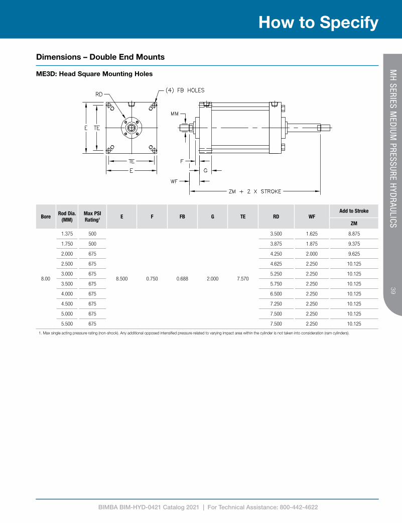
ME3D: Head Square Mounting Holes
1. Max single acting pressure rating (non-shock). Any additional opposed intensified pressure related to varying impact area within the cylinder is not taken into consideration (ram cylinders).
BoreRod Dia.
(MM)Max PSI Rating1 E F FB G TE RD WF
Add to Stroke
ZM
8.00
1.375 500
8.500 0.750 0.688 2.000 7.570
3.500 1.625 8.875
1.750 500 3.875 1.875 9.375
2.000 675 4.250 2.000 9.625
2.500 675 4.625 2.250 10.125
3.000 675 5.250 2.250 10.125
3.500 675 5.750 2.250 10.125
4.000 675 6.500 2.250 10.125
4.500 675 7.250 2.250 10.125
5.000 675 7.500 2.250 10.125
5.500 675 7.500 2.250 10.125
BIMBA BIM-HYD-0421 Catalog 2021 | For Technical Assistance: 800-442-4622
40
How to Specify
MH
SERIES MED
IUM PRESSURE H
YDRAULICS
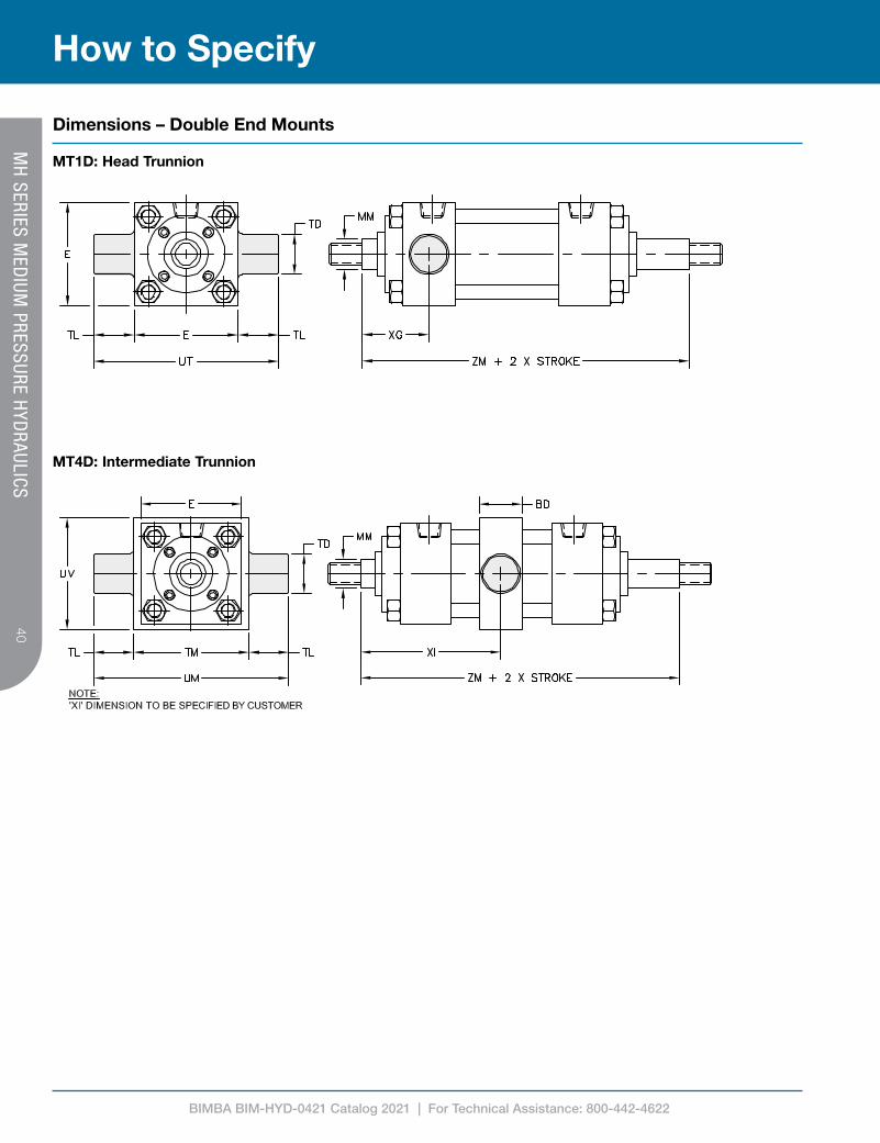
Dimensions – Double End Mounts
MT1D: Head Trunnion
MT4D: Intermediate Trunnion
BIMBA BIM-HYD-0421 Catalog 2021 | For Technical Assistance: 800-442-4622
4141
How to SpecifyM
H SERIES M
EDIUM
PRESSURE HYD
RAULICS
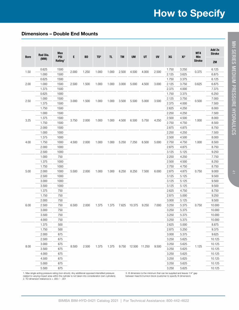
Dimensions – Double End Mounts
BoreRod Dia.
(MM)
Max PSI
Rating1
E BD TD2 TL TM UM UT UV XG XI3
MT4Min
Stroke
Add 2x Stroke
ZM
1.500.625 1500
2.000 1.250 1.000 1.000 2.500 4.500 4.000 2.5001.750 3.250
0.3756.125
1.000 1500 2.125 3.625 6.875
2.00
0.625 1500
2.500 1.500 1.000 1.000 3.000 5.000 4.500 3.000
1.750 3.375
0.625
6.125
1.000 1500 2.125 3.750 6.875
1.375 1500 2.375 4.000 7.375
2.50
0.625 1000
3.000 1.500 1.000 1.000 3.500 5.500 5.000 3.500
1.750 3.375
0.500
6.250
1.000 1500 2.125 3.750 7.000
1.375 1500 2.375 4.000 7.500
1.750 1500 2.625 4.250 8.000
3.25
1.000 1500
3.750 2.000 1.000 1.000 4.500 6.500 5.750 4.250
2.250 4.250
1.000
7.500
1.375 1500 2.500 4.500 8.000
1.750 1500 2.750 4.750 8.500
2.000 1500 2.875 4.875 8.750
4.00
1.000 1000
4.500 2.000 1.000 1.000 5.250 7.250 6.500 5.000
2.250 4.250
1.000
7.500
1.375 1000 2.500 4.500 8.000
1.750 1000 2.750 4.750 8.500
2.000 1000 2.875 4.875 8.750
2.500 1000 3.125 5.125 9.250
5.00
1.000 750
5.500 2.000 1.000 1.000 6.250 8.250 7.500 6.000
2.250 4.250
0.750
7.750
1.375 1000 2.500 4.500 8.250
1.750 1000 2.750 4.750 8.750
2.000 1000 2.875 4.875 9.000
2.500 1000 3.125 5.125 9.500
3.000 1000 3.125 5.125 9.500
3.500 1000 3.125 5.125 9.500
6.00
1.375 750
6.500 2.000 1.375 1.375 7.625 10.375 9.250 7.000
2.625 4.750
0.750
8.750
1.750 750 2.875 5.000 9.250
2.000 750 3.000 5.125 9.500
2.500 750 3.250 5.375 10.000
3.000 750 3.250 5.375 10.000
3.500 750 3.250 5.375 10.000
4.000 750 3.250 5.375 10.000
8.00
1.375 500
8.500 2.500 1.375 1.375 9.750 12.500 11.250 9.500
2.625 5.000
1.125
8.875
1.750 500 2.875 5.250 9.375
2.000 675 3.000 5.375 9.625
2.500 675 3.250 5.625 10.125
3.000 675 3.250 5.625 10.125
3.500 675 3.250 5.625 10.125
4.000 675 3.250 5.625 10.125
4.500 675 3.250 5.625 10.125
5.000 675 3.250 5.625 10.125
5.500 675 3.250 5.625 10.125
1. Max single acting pressure rating (non-shock). Any additional opposed intensified pressure related to varying impact area within the cylinder is not taken into consideration (ram cylinders).2. TD dimension tolerance is + .000 / - .001
3. XI dimension is the minimum that can be supplied and leaves 1/4” gap between head & trunnion block (customer to specify XI dimension).

BIMBA BIM-HYD-0421 Catalog 2021 | For Technical Assistance: 800-442-4622
42
How to Specify
MH
SERIES MED
IUM PRESSURE H
YDRAULICS
Dimensions – Double End Mounts
MX1D: Extended Tie Rods - Head & Cap
MX3D: Extended Tie Rods - Head End
BIMBA BIM-HYD-0421 Catalog 2021 | For Technical Assistance: 800-442-4622
4343
How to SpecifyM
H SERIES M
EDIUM
PRESSURE HYD
RAULICS
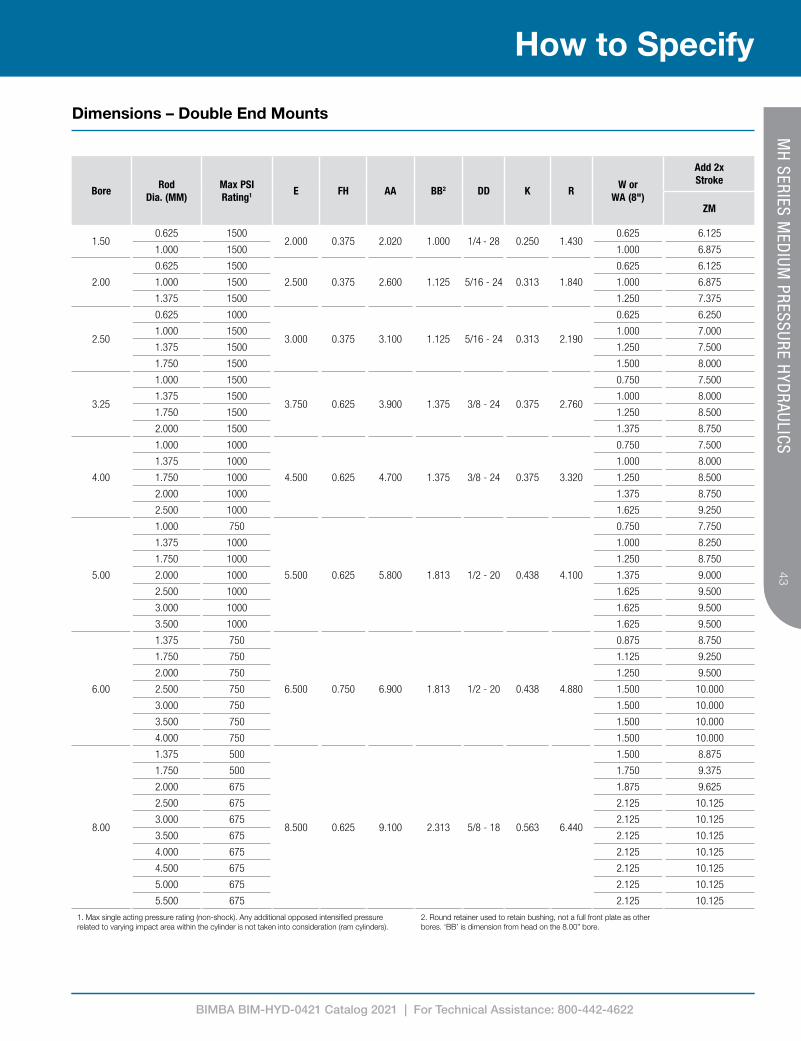
Dimensions – Double End Mounts
1. Max single acting pressure rating (non-shock). Any additional opposed intensified pressure related to varying impact area within the cylinder is not taken into consideration (ram cylinders).
2. Round retainer used to retain bushing, not a full front plate as other bores. ‘BB’ is dimension from head on the 8.00” bore.
BoreRod
Dia. (MM)Max PSI Rating1 E FH AA BB2 DD K R
W or WA (8")
Add 2x Stroke
ZM
1.500.625 1500
2.000 0.375 2.020 1.000 1/4 - 28 0.250 1.4300.625 6.125
1.000 1500 1.000 6.875
2.00
0.625 1500
2.500 0.375 2.600 1.125 5/16 - 24 0.313 1.840
0.625 6.125
1.000 1500 1.000 6.875
1.375 1500 1.250 7.375
2.50
0.625 1000
3.000 0.375 3.100 1.125 5/16 - 24 0.313 2.190
0.625 6.250
1.000 1500 1.000 7.000
1.375 1500 1.250 7.500
1.750 1500 1.500 8.000
3.25
1.000 1500
3.750 0.625 3.900 1.375 3/8 - 24 0.375 2.760
0.750 7.500
1.375 1500 1.000 8.000
1.750 1500 1.250 8.500
2.000 1500 1.375 8.750
4.00
1.000 1000
4.500 0.625 4.700 1.375 3/8 - 24 0.375 3.320
0.750 7.500
1.375 1000 1.000 8.000
1.750 1000 1.250 8.500
2.000 1000 1.375 8.750
2.500 1000 1.625 9.250
5.00
1.000 750
5.500 0.625 5.800 1.813 1/2 - 20 0.438 4.100
0.750 7.750
1.375 1000 1.000 8.250
1.750 1000 1.250 8.750
2.000 1000 1.375 9.000
2.500 1000 1.625 9.500
3.000 1000 1.625 9.500
3.500 1000 1.625 9.500
6.00
1.375 750
6.500 0.750 6.900 1.813 1/2 - 20 0.438 4.880
0.875 8.750
1.750 750 1.125 9.250
2.000 750 1.250 9.500
2.500 750 1.500 10.000
3.000 750 1.500 10.000
3.500 750 1.500 10.000
4.000 750 1.500 10.000
8.00
1.375 500
8.500 0.625 9.100 2.313 5/8 - 18 0.563 6.440
1.500 8.875
1.750 500 1.750 9.375
2.000 675 1.875 9.625
2.500 675 2.125 10.125
3.000 675 2.125 10.125
3.500 675 2.125 10.125
4.000 675 2.125 10.125
4.500 675 2.125 10.125
5.000 675 2.125 10.125
5.500 675 2.125 10.125
BIMBA BIM-HYD-0421 Catalog 2021 | For Technical Assistance: 800-442-4622
44
How to Specify
MH
SERIES MED
IUM PRESSURE H
YDRAULICS
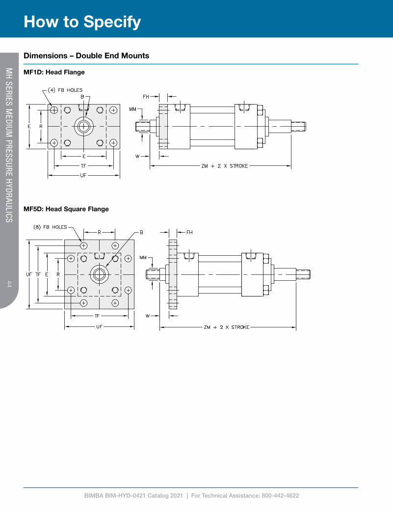
Dimensions – Double End Mounts
MF1D: Head Flange
MF5D: Head Square Flange

BIMBA BIM-HYD-0421 Catalog 2021 | For Technical Assistance: 800-442-4622
4545
How to SpecifyM
H SERIES M
EDIUM
PRESSURE HYD
RAULICS
Dimensions – Double End Mounts
1. Max single acting pressure rating (non-shock). Any additional opposed intensified pressure related to varying impact area within the cylinder is not taken into consideration (ram cylinders).
2. B dimension tolerance is +.000 / -.002
BoreRod
Dia. (MM)Max PSI Rating1 B2 E FB FH R TF UF W
Add 2x Stroke
ZM
1.500.625 1500 1.124
2.000 0.313 0.375 1.430 2.750 3.3750.625 6.125
1.000 1500 1.499 1.000 6.875
2.00
0.625 1500 1.124
2.500 0.375 0.375 1.840 3.375 4.125
0.625 6.125
1.000 1500 1.499 1.000 6.875
1.375 1500 1.999 1.250 7.375
2.50
0.625 1000 1.124
3.000 0.375 0.375 2.190 3.875 4.625
0.625 6.250
1.000 1500 1.499 1.000 7.000
1.375 1500 1.999 1.250 7.500
1.750 1500 2.374 1.500 8.000
3.25
1.000 1500 1.499
3.750 0.438 0.625 2.760 4.688 5.500
0.750 7.500
1.375 1500 1.999 1.000 8.000
1.750 1500 2.374 1.250 8.500
2.000 1500 2.624 1.375 8.750
4.00
1.000 1000 1.499
4.500 0.438 0.625 3.320 5.438 6.250
0.750 7.500
1.375 1000 1.999 1.000 8.000
1.750 1000 2.374 1.250 8.500
2.000 1000 2.624 1.375 8.750
2.500 1000 3.124 1.625 9.250
5.00
1.000 750 1.499
5.500 0.563 0.625 4.100 6.625 7.625
0.750 7.750
1.375 1000 1.999 1.000 8.250
1.750 1000 2.374 1.250 8.750
2.000 1000 2.624 1.375 9.000
2.500 1000 3.124 1.625 9.500
3.000 1000 3.749 1.625 9.500
3.500 1000 4.249 1.625 9.500
6.00
1.375 750 1.999
6.500 0.563 0.750 4.880 7.625 8.625
0.875 8.750
1.750 750 2.374 1.125 9.250
2.000 750 2.624 1.250 9.500
2.500 750 3.124 1.500 10.000
3.000 750 3.749 1.500 10.000
3.500 750 4.249 1.500 10.000
4.000 750 4.749 1.500 10.000

BIMBA BIM-HYD-0421 Catalog 2021 | For Technical Assistance: 800-442-4622
46
How to Specify
MH
SERIES MED
IUM PRESSURE H
YDRAULICS
Dimensions – Double End Mounts
MS2D: Side Lugs
MS3D: Center Line Lugs
BIMBA BIM-HYD-0421 Catalog 2021 | For Technical Assistance: 800-442-4622
4747
How to SpecifyM
H SERIES M
EDIUM
PRESSURE HYD
RAULICS
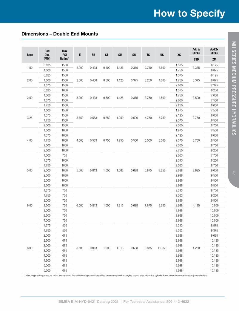
Dimensions – Double End Mounts
BoreRod Dia.
(MM)
Max PSI
Rating1
E SB ST SU SW TS US XS
Add to Stroke
Add 2x Stroke
SSD ZM
1.500.625 1500
2.000 0.438 0.500 1.125 0.375 2.750 3.5001.375
3.3756.125
1.000 1500 1.750 6.875
2.00
0.625 1500
2.500 0.438 0.500 1.125 0.375 3.250 4.000
1.375
3.375
6.125
1.000 1500 1.750 6.875
1.375 1500 2.000 7.375
2.50
0.625 1000
3.000 0.438 0.500 1.125 0.375 3.750 4.500
1.375
3.500
6.250
1.000 1500 1.750 7.000
1.375 1500 2.000 7.500
1.750 1500 2.250 8.000
3.25
1.000 1500
3.750 0.563 0.750 1.250 0.500 4.750 5.750
1.875
3.750
7.500
1.375 1500 2.125 8.000
1.750 1500 2.375 8.500
2.000 1500 2.500 8.750
4.00
1.000 1000
4.500 0.563 0.750 1.250 0.500 5.500 6.500
1.875
3.750
7.500
1.375 1000 2.125 8.000
1.750 1000 2.375 8.500
2.000 1000 2.500 8.750
2.500 1000 2.750 9.250
5.00
1.000 750
5.500 0.813 1.000 1.063 0.688 6.875 8.250
2.063
3.625
7.750
1.375 1000 2.313 8.250
1.750 1000 2.563 8.750
2.000 1000 2.688 9.000
2.500 1000 2.938 9.500
3.000 1000 2.938 9.500
3.500 1000 2.938 9.500
6.00
1.375 750
6.500 0.813 1.000 1.313 0.688 7.875 9.250
2.313
4.125
8.750
1.750 750 2.563 9.250
2.000 750 2.688 9.500
2.500 750 2.938 10.000
3.000 750 2.938 10.000
3.500 750 2.938 10.000
4.000 750 2.938 10.000
8.00
1.375 500
8.500 0.813 1.000 1.313 0.688 9.875 11.250
2.313
4.250
8.875
1.750 500 2.563 9.375
2.000 675 2.688 9.625
2.500 675 2.938 10.125
3.000 675 2.938 10.125
3.500 675 2.938 10.125
4.000 675 2.938 10.125
4.500 675 2.938 10.125
5.000 675 2.938 10.125
5.500 675 2.938 10.125
1. Max single acting pressure rating (non-shock). Any additional opposed intensified pressure related to varying impact area within the cylinder is not taken into consideration (ram cylinders).
BIMBA BIM-HYD-0421 Catalog 2021 | For Technical Assistance: 800-442-4622
48
How to Specify
MH
SERIES MED
IUM PRESSURE H
YDRAULICS
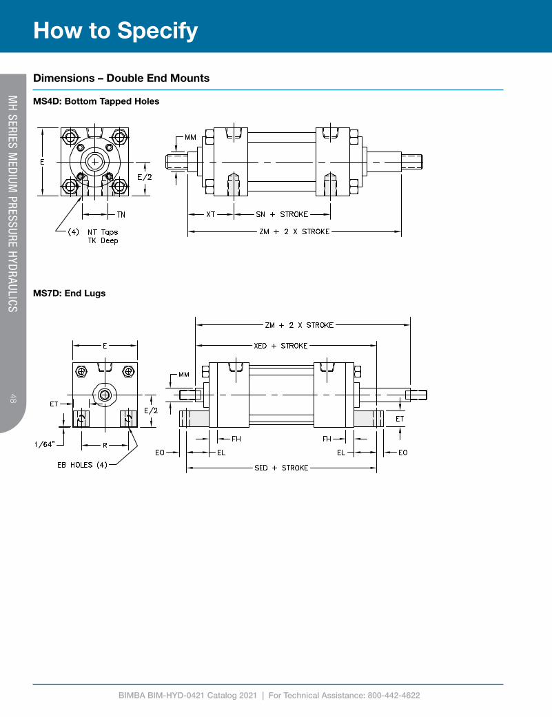
Dimensions – Double End Mounts
MS4D: Bottom Tapped Holes
MS7D: End Lugs
BIMBA BIM-HYD-0421 Catalog 2021 | For Technical Assistance: 800-442-4622
4949
How to SpecifyM
H SERIES M
EDIUM
PRESSURE HYD
RAULICS
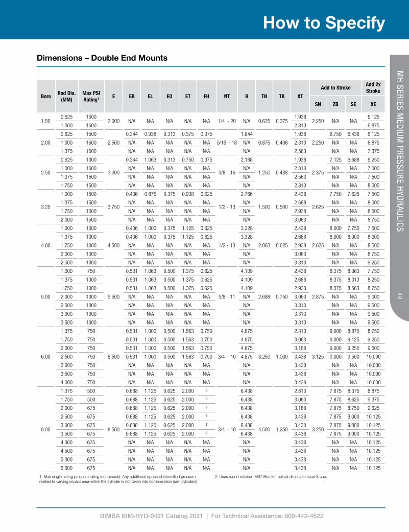
Dimensions – Double End Mounts
1. Max single acting pressure rating (non-shock). Any additional opposed intensified pressure related to varying impact area within the cylinder is not taken into consideration (ram cylinders).
2. Uses round retainer. MS7 Bracket bolted directly to head & cap.
BoreRod Dia.
(MM)Max PSI Rating1 E EB EL EO ET FH NT R TN TK XT
Add to StrokeAdd 2x Stroke
SN ZB SE XE
1.500.625 1500
2.000 N/A N/A N/A N/A N/A 1/4 - 20 N/A 0.625 0.3751.938
2.250 N/A N/A6.125
1.000 1500 2.313 6.875
2.00
0.625 1500
2.500
0.344 0.938 0.313 0.375 0.375
5/16 - 18
1.844
0.875 0.406
1.938
2.250
6.750 6.438 6.125
1.000 1500 N/A N/A N/A N/A N/A N/A 2.313 N/A N/A 6.875
1.375 1500 N/A N/A N/A N/A N/A N/A 2.563 N/A N/A 7.375
2.50
0.625 1000
3.000
0.344 1.063 0.313 0.750 0.375
3/8 - 16
2.188
1.250 0.438
1.938
2.375
7.125 6.688 6.250
1.000 1500 N/A N/A N/A N/A N/A N/A 2.313 N/A N/A 7.000
1.375 1500 N/A N/A N/A N/A N/A N/A 2.563 N/A N/A 7.500
1.750 1500 N/A N/A N/A N/A N/A N/A 2.813 N/A N/A 8.000
3.25
1.000 1500
3.750
0.406 0.875 0.375 0.938 0.625
1/2 - 13
2.766
1.500 0.500
2.438
2.625
7.750 7.625 7.500
1.375 1500 N/A N/A N/A N/A N/A N/A 2.688 N/A N/A 8.000
1.750 1500 N/A N/A N/A N/A N/A N/A 2.938 N/A N/A 8.500
2.000 1500 N/A N/A N/A N/A N/A N/A 3.063 N/A N/A 8.750
4.00
1.000 1000
4.500
0.406 1.000 0.375 1.125 0.625
1/2 - 13
3.328
2.063 0.625
2.438
2.625
8.000 7.750 7.500
1.375 1000 0.406 1.000 0.375 1.125 0.625 3.328 2.688 8.000 8.000 8.000
1.750 1000 N/A N/A N/A N/A N/A N/A 2.938 N/A N/A 8.500
2.000 1000 N/A N/A N/A N/A N/A N/A 3.063 N/A N/A 8.750
2.500 1000 N/A N/A N/A N/A N/A N/A 3.313 N/A N/A 9.250
5.00
1.000 750
5.500
0.531 1.063 0.500 1.375 0.625
5/8 - 11
4.109
2.688 0.750
2.438
2.875
8.375 8.063 7.750
1.375 1000 0.531 1.063 0.500 1.375 0.625 4.109 2.688 8.375 8.313 8.250
1.750 1000 0.531 1.063 0.500 1.375 0.625 4.109 2.938 8.375 8.563 8.750
2.000 1000 N/A N/A N/A N/A N/A N/A 3.063 N/A N/A 9.000
2.500 1000 N/A N/A N/A N/A N/A N/A 3.313 N/A N/A 9.500
3.000 1000 N/A N/A N/A N/A N/A N/A 3.313 N/A N/A 9.500
3.500 1000 N/A N/A N/A N/A N/A N/A 3.313 N/A N/A 9.500
6.00
1.375 750
6.500
0.531 1.000 0.500 1.563 0.750
3/4 - 10
4.875
3.250 1.000
2.813
3.125
9.000 8.875 8.750
1.750 750 0.531 1.000 0.500 1.563 0.750 4.875 3.063 9.000 9.125 9.250
2.000 750 0.531 1.000 0.500 1.563 0.750 4.875 3.188 9.000 9.250 9.500
2.500 750 0.531 1.000 0.500 1.563 0.750 4.875 3.438 9.000 9.500 10.000
3.000 750 N/A N/A N/A N/A N/A N/A 3.438 N/A N/A 10.000
3.500 750 N/A N/A N/A N/A N/A N/A 3.438 N/A N/A 10.000
4.000 750 N/A N/A N/A N/A N/A N/A 3.438 N/A N/A 10.000
8.00
1.375 500
8.500
0.688 1.125 0.625 2.000 2
3/4 - 10
6.438
4.500 1.250
2.813
3.250
7.875 8.375 8.875
1.750 500 0.688 1.125 0.625 2.000 2 6.438 3.063 7.875 8.625 9.375
2.000 675 0.688 1.125 0.625 2.000 2 6.438 3.188 7.875 8.750 9.625
2.500 675 0.688 1.125 0.625 2.000 2 6.438 3.438 7.875 9.000 10.125
3.000 675 0.688 1.125 0.625 2.000 2 6.438 3.438 7.875 9.000 10.125
3.500 675 0.688 1.125 0.625 2.000 2 6.438 3.438 7.875 9.000 10.125
4.000 675 N/A N/A N/A N/A N/A N/A 3.438 N/A N/A 10.125
4.500 675 N/A N/A N/A N/A N/A N/A 3.438 N/A N/A 10.125
5.000 675 N/A N/A N/A N/A N/A N/A 3.438 N/A N/A 10.125
5.500 675 N/A N/A N/A N/A N/A N/A 3.438 N/A N/A 10.125

BIMBA BIM-HYD-0421 Catalog 2021 | For Technical Assistance: 800-442-4622
50
How to Order
MH
SERIES MED
IUM PRESSURE H
YDRAULICS
MH-MF1 -250 x 10-H2C6-100-KK1-P15 = N375-SSSS-
Product Series
MH Medium Pressure Hydraulic
Style
Single Rod
D Double Rod
Stroke
0” to 120” Made to Order.
(Use decimals for fractional strokes)
Rod Size
062 0.625” Rod Dia.
100 1.000” Rod Dia.
137 1.375” Rod Dia.
175 1.750” Rod Dia.
200 2.000” Rod Dia.
250 2.500” Rod Dia.
300 3.000” Rod Dia.
350 3.500” Rod Dia.
400 4.000” Rod Dia.
450 4.500” Rod Dia.
500 5.000” Rod Dia.
550 5.500” Rod Dia.
Piston Seal
S Standard (Carboxilated)
C Cast-Ring
E EP
T PTFE4
V Fluorocarbon
Rod Seal
S Standard (Polyurethane)
E EP
V Fluorocarbon
Tube Seal
S Standard (Buna)
E EP
V Fluorocarbon
Rod Wiper4
S Standard (Flocked Nitrile)
M Metallic Scraper
T PTFE
V Fluorocarbon
Rod End²
KK1 Small Male Thread
KK2 Large Male Thread
KK3 Female Thread
KK3M Female Metric Rod Thread
KK3X Female Special Thread
KK4 Full Diameter Male Thread
KK5 Plain End
KK10 Rod Coupler End
KKM Metric Thread
KKX Male Special Thread
Port Loc³
P 1
2
3
4
5
6
7
8
9
Bore
150 1.50”
200 2.00”
250 2.50”
325 3.25”
400 4.00”
500 5.00”
600 6.00”
800 8.00”
Cushions1
H 1
2
3
4
C 5
6
7
8
NFPA Mounts
MX0 No Mount (1.50” to 8.00” Bore)
MF1 Head Rectangular Flange (1.50” to 6.00” Bore)
MF2 Cap Rectangular Flange (1.50” to 6.00” Bore)
MF5 Head Square Flange (1.50” to 6.00” Bore)
MF6 Cap Square Flange (1.50” to 6.00” Bore)
ME3 Head Mounting Holes (8.00” Bore)
ME4 Cap Mounting Holes (8.00” Bore)
MP1 Fixed Cap Pivot Clevis (1.50” to 8.00” Bore)
MP2 Detachable Cap Pivot Clevis (1.50” to 6.00” Bore)
MS2 Side Lugs (1.50” to 8.00” Bore)
MS3 Center Line Lugs (1.50” to 8.00” Bore)
MS4 Bottom Tapped Holes (1.50” to 8.00” Bore)
MS7 End Lugs (1.50” to 8.00” Bore)
MT1 Head Trunnion (1.50” to 8.00” Bore)
MT2 Cap Trunnion (1.50” to 8.00” Bore)
MT4 Intermediate (Center) Trunnion (1.50” to 8.00” Bore)
MX1 Extended Tie Rods - Head & Cap (1.50” to 8.00” Bore)
MX2 Extended Tie Rods - Cap (1.50” to 8.00” Bore)
MX3 Extended Tie Rods - Head (1.50” to 8.00” Bore)
SB Spherical Bearing Cap Pivot (1.50” to 8.00” Bore)
Port Size
N062 1/16” NPTF
N125 1/8” NPTF
N250 1/4” NPTF
N375 3/8” NPTF
N500 1/2” NPTF
N750 3/4” NPTF
S6 #6 SAE
S8 #8 SAE
S10 #10 SAE
S12 #12 SAE
1. Call out ‘H’ for head cushion, ‘C’ for cap cushion, followed by the desired location(s).2. When additional thread details are required, use format: Rod End = Modification Example: KKM=M12 x 1.753. Call out ‘P’ followed by all desired locations.4. When cylinder design calls for all EP seals, use PTFE rod wiper. 5. The desired stop tube length adds directly to the overall cylinder length.Note: Refer to MH Options for specifications.
Options
A= Extended Piston Rod Thread (Example: A = 2”)(Max = 2 Times ST’D “A” Dim.)
ABP= Air Bleed Ports (Example: ABP=15)
AS= Adjustable Stroke - Retract (Specify Length, Example: AS = 4”)
C=Extended Piston Rod
(Example: if C = 0.50”, Then 1” Rod Extension is C = 1.50”)
CS Center Support
DBB= Drain Back Bushing (Example: DBB=1)
EK Extended Key Plate
HLP High Load Piston
HSS High Shock Seals
LRB Lift Ring Boss
NR Non-Rotating
PLS Piston Lock Screw (Standard)
RBB Rod Bushing Material: Bronze
SSR Stainless Steel Piston Rod
ST=5
Stop Tube Note: Specify Stop Tube Length (in inches) Specify Stroke as ES (effective stroke) Example: MH-MS2-250x48 ES-H2C6-ST=36
4WF Four Wrench Flats (Rod Sizes: .625”-3.50”)
XX= Special Variation (Specify)
MH Cylinders
BIMBA BIM-HYD-0421 Catalog 2021 | For Technical Assistance: 800-442-4622
5151
How to Order
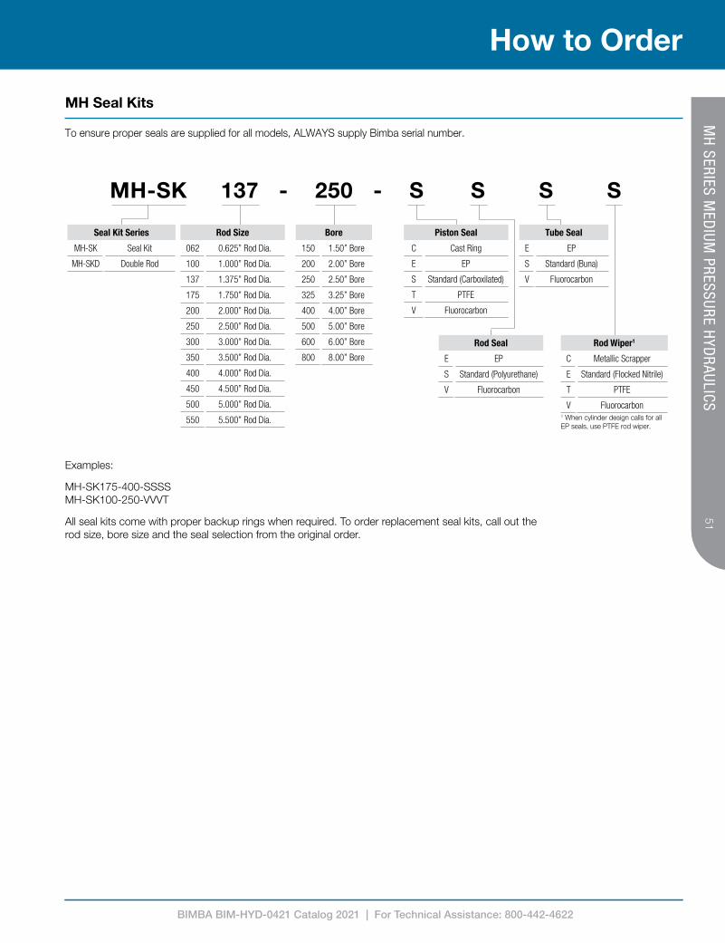
MH Seal Kits
1 When cylinder design calls for all EP seals, use PTFE rod wiper.
To ensure proper seals are supplied for all models, ALWAYS supply Bimba serial number.
MH-SK 137 - 250 - S S S S
Seal Kit Series
MH-SK Seal Kit
MH-SKD Double Rod
Examples:
MH-SK175-400-SSSS MH-SK100-250-VVVT
All seal kits come with proper backup rings when required. To order replacement seal kits, call out the rod size, bore size and the seal selection from the original order.
Rod Size
062 0.625” Rod Dia.
100 1.000” Rod Dia.
137 1.375” Rod Dia.
175 1.750” Rod Dia.
200 2.000” Rod Dia.
250 2.500” Rod Dia.
300 3.000” Rod Dia.
350 3.500” Rod Dia.
400 4.000” Rod Dia.
450 4.500” Rod Dia.
500 5.000” Rod Dia.
550 5.500” Rod Dia.
Bore
150 1.50” Bore
200 2.00” Bore
250 2.50” Bore
325 3.25” Bore
400 4.00” Bore
500 5.00” Bore
600 6.00” Bore
800 8.00” Bore
Rod Wiper1
C Metallic Scrapper
E Standard (Flocked Nitrile)
T PTFE
V Fluorocarbon
Piston Seal
C Cast Ring
E EP
S Standard (Carboxilated)
T PTFE
V Fluorocarbon
Tube Seal
E EP
S Standard (Buna)
V Fluorocarbon
Rod Seal
E EP
S Standard (Polyurethane)
V Fluorocarbon
MH
SERIES MED
IUM PRESSURE H
YDRAULICS
BIMBA BIM-HYD-0421 Catalog 2021 | For Technical Assistance: 800-442-4622
52
Product Features
Index to Options
53 A = Extended Piston Rod Thread
53 AS = Adjustable Stroke (Retract)
53 ABP = Air Bleed Ports
53 C = Extended Piston Rod
54 CS = Center Support
54 C or H = Cushions
54 DBB = Drain Back Bushing
55 EK = Extended Key Plate
55 T = PTFE Piston Seal
56 HSS = High Shock Seals
56 KKX = Non-Standard Rod Threads
56 KKM = Male Metric Rod Threads
56 KK3M = Female Metric Rod Threads
56 KK3X = Female Special Rod Threads
56 LRB = Lift Ring Boss
57 NR = Non-Rotating
57 Multiple Mounts
58 Port Options (BSPP, BSPT, NPTF)
58 RBB = Rod Bushing - Bronze (Ductile Iron is standard)
58 SSR = Stainless Steel Piston Rod
59 Seals (Piston, Rod, Tube, Wiper)
60 ST = Stop Tube & Rod Size Selection
61 Piston Rod Size Selection
62 3P = Three-Position Cylinders
62 BTB = Back-To-Back Cylinders
62 TM = Tandem Cylinders
62 Special Finishes
BIMBA BIM-HYD-0421 Catalog 2021 | For Technical Assistance: 800-442-4622
5353
How to CustomizeM
H SERIES O
PTION
S
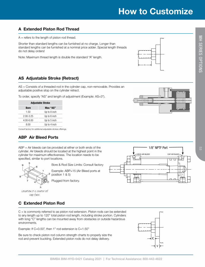
A Extended Piston Rod Thread
A = refers to the length of piston rod thread.
Shorter than standard lengths can be furnished at no charge. Longer than standard lengths can be furnished at a nominal price adder. Special length threads do not delay orders!
Note: Maximum thread length is double the standard “A” length.
Adjustable Stroke
Bore Max “AS”
1.50 Up to 8 inch
2.00-3.25 Up to 6 inch
4.00-6.00 Up to 5 inch
8.00 Up to 4 inch
Consult factory for additional adjustable strokes offerings.
AS = Consists of a threaded rod in the cylinder cap, non-removable. Provides an adjustable positive stop on the cylinder retract.
To order, specify “AS” and length of adjustment (Example: AS=3").
AS Adjustable Stroke (Retract)
Location 9 is center of cap face.
HEAD AIR BLEED CAP AIR BLEED
1/8” NPTF PortABP = Air bleeds can be provided at either or both ends of the cylinder. Air bleeds should be located at the highest point in the cylinder for maximum effectiveness. The location needs to be specified, similar to port locations.
Bore & Rod Size Limits: Consult factory
Example: ABP=15 (Air Bleed ports at position 1 & 5)
Plugged from factory.
ABP Air Bleed Ports
C
C = is commonly referred to as piston rod extension. Piston rods can be extended to any length up to 120” total piston rod length, including stroke portion. Cylinders with long “C” lengths can be mounted away from obstacles or outside hazardous environments.
Example: If C=0.50”, then 1” rod extension is C=1.50”
Be sure to check piston rod column strength charts to properly size the rod and prevent buckling. Extended piston rods do not delay delivery.
C Extended Piston Rod
BIMBA BIM-HYD-0421 Catalog 2021 | For Technical Assistance: 800-442-4622
54
How to Customize
MH
SERIES OPTIO
NS
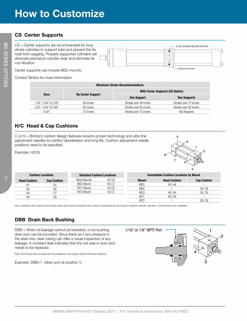
CS = Center supports are recommended for long stroke cylinders to support tube and prevent the tie rods from sagging. Properly supported cylinders will eliminate premature cylinder wear and eliminate tie rod vibration.
Center supports can include MS2 mounts.
Contact Bimba for more information.
Note: Cylinders with a short stroke (value varies with bore/rod diameter and cushion combinations) may result in improper cylinder operation. Consult factory for availability.
Cushion Locations
Head Cushion Cap CushionH1 C5H2 C6H3 C7H4 C8
Standard Cushion LocationsMost Mounts H2 C6MS3 Mount H3 C7MT1 Mount H3 C6MT2 Mount H2 C7
Unavailable Cushion Locations by Mount
Mount Head Cushion Cap CushionME5 H2, H4 –ME6 – C6, C8MS3 H2, H4 C6, C8MT1 H2, H4 –MT2 – C6, C8
C or H = Bimba’s cushion design features industry proven technology and ultra fine adjustment needles for perfect deceleration and long life. Cushion adjustment needle positions need to be specified.
Example: H2C6
Maximum Stroke Recommendations
Bore No Center SupportWith Center Supports (CS Option)
One Support Two Supports
1.50", 2.00" & 2.50" 48 inches Strokes over 48 inches Strokes over 72 inches3.25”, 4.00" & 5.00" 65 inches Strokes over 65 inches Strokes over 92 inches
6.00” 72 inches Strokes over 72 inches Not Required
CS Center Supports
DBB = When oil leakage cannot be tolerated, a rod bushing drain port can be provided. Since there isn’t any pressure in the drain line, clear tubing can offer a visual inspection of any leakage. A constant leak indicates that the rod seal is worn and needs to be replaced.
Note: Some bore and rod sizes are not available or may require special thickness retainers.
Example: DBB=1 (drain port at position 1)
1/16" or 1/8" NPTF Port
H/C Head & Cap Cushions
DBB Drain Back Bushing

BIMBA BIM-HYD-0421 Catalog 2021 | For Technical Assistance: 800-442-4622
5555
How to Customize
> Design Benefits » Bi-direction piston seal offers low leakage rating » Piston seal design offers lower friction
than cast iron rings or lip seals, which eliminate stick/slip breakaway issues
» Glass filled PTFE piston seal is 20% stronger than bronze filled seals
» High contamination tolerant; offers the longest life of any seal type
» Temperature Rating (PTFE): -100°F to 400°F (-73°C to 204°C)
» Temperature Rating (Nitrile): -20°F to 200°F (-29°C to 93°C)
» Temperature Rating (FKM): 0°F to 400°F (-18°C to 204°C)
> High Load Piston Wear Band - Our superior design is 35% to 80% wider than competitive models and we locate the wear band at the furthest point from the rod bearing to increase overall effectiveness
> Piston Ring Seal - Glass filled PTFE with Nitrile* expander.
MH
SERIES OPTIO
NS
EK Extended Key Plate
**
MH Dimensions Extended Key Plate
Bore E FA* FH PA*
1.50 2.000 0.312 / 0.310 0.375 0.188
2.00 2.500 0.312 / 0.310 0.375 0.188
2.50 3.000 0.312 / 0.310 0.375 0.188
3.25 3.750 0.562 / 0.560 0.625 0.313
4.00 4.500 0.562 / 0.560 0.625 0.313
5.00 5.500 0.562 / 0.560 0.625 0.313
6.00 6.500 0.687 / 0.685 0.750 0.375
EK = Extended key plate or thrust key is made from a full square bushing retainer plate. The key is designed to fit in a milled slot on the equipment to prevent the cylinder from shifting.
An additional mount needs to be specified to secure cylinder.
Available Bore Sizes: 1.50" to 6.00"
* FA & PA dimensions will have a black oxide finish and will not be painted.
HEAVY-DUTY HYDRAULICPTFE PISTON RING SEAL
EXTRA LARGE, HIGH LOADPISTON WEAR BAND
Long stroke cylinders and pivot type mounting can create severe cylinder piston-to-tube side loads. The PTFE piston seal provides increased side load capacity and low friction without increasing the cylinder base dimensions.
* Other materials are available, consult factory.
Option T (PTFE) Piston Seal - Recommended for High Load & Low Friction Applications
BIMBA BIM-HYD-0421 Catalog 2021 | For Technical Assistance: 800-442-4622
56
How to Customize
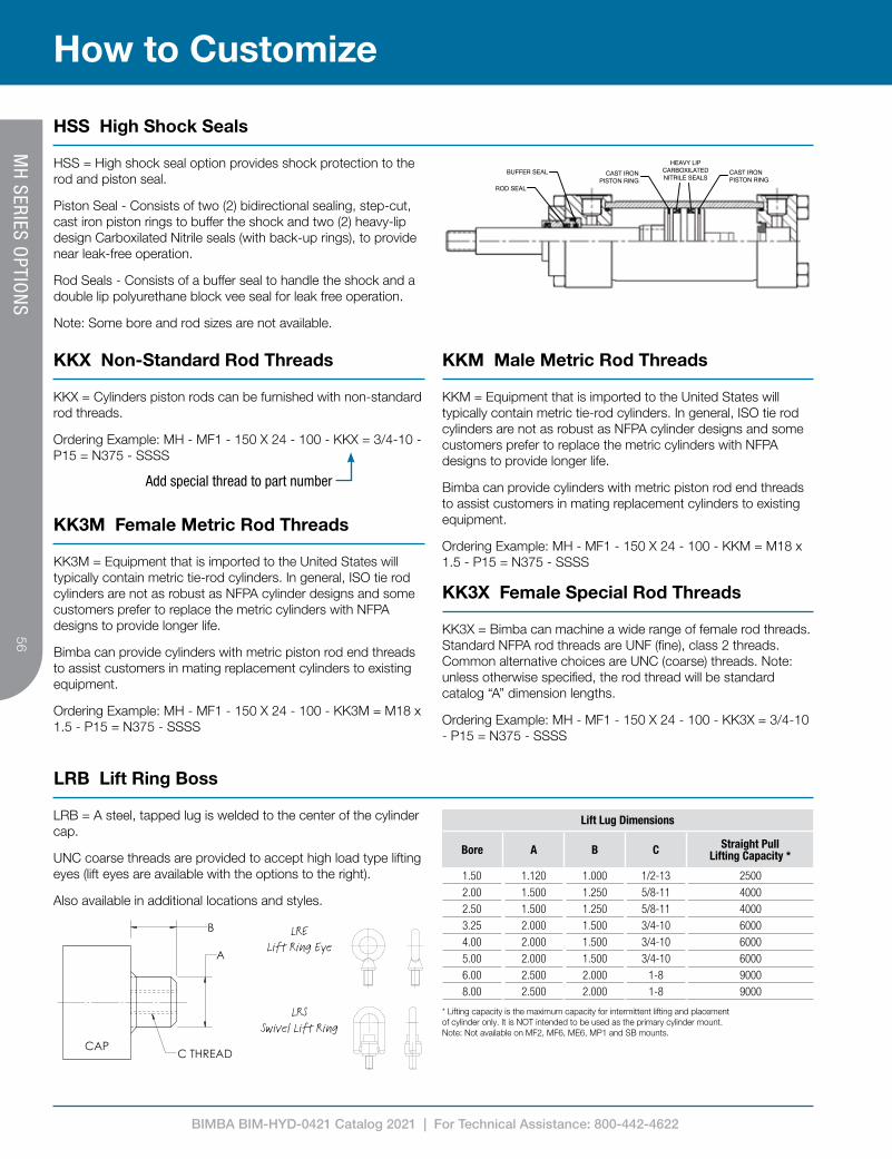
HSS High Shock Seals
CAST IRONPISTON RING
CAST IRONPISTON RING
HEAVY LIPCARBOXILATEDNITRILE SEALS
BUFFER SEAL
ROD SEAL
Add special thread to part number
HSS = High shock seal option provides shock protection to the rod and piston seal.
Piston Seal - Consists of two (2) bidirectional sealing, step-cut, cast iron piston rings to buffer the shock and two (2) heavy-lip design Carboxilated Nitrile seals (with back-up rings), to provide near leak-free operation.
Rod Seals - Consists of a buffer seal to handle the shock and a double lip polyurethane block vee seal for leak free operation.
Note: Some bore and rod sizes are not available.
KKX = Cylinders piston rods can be furnished with non-standard rod threads.
Ordering Example: MH - MF1 - 150 X 24 - 100 - KKX = 3/4-10 - P15 = N375 - SSSS
KK3M = Equipment that is imported to the United States will typically contain metric tie-rod cylinders. In general, ISO tie rod cylinders are not as robust as NFPA cylinder designs and some customers prefer to replace the metric cylinders with NFPA designs to provide longer life.
Bimba can provide cylinders with metric piston rod end threads to assist customers in mating replacement cylinders to existing equipment.
Ordering Example: MH - MF1 - 150 X 24 - 100 - KK3M = M18 x 1.5 - P15 = N375 - SSSS
KK3X = Bimba can machine a wide range of female rod threads. Standard NFPA rod threads are UNF (fine), class 2 threads. Common alternative choices are UNC (coarse) threads. Note: unless otherwise specified, the rod thread will be standard catalog “A” dimension lengths.
Ordering Example: MH - MF1 - 150 X 24 - 100 - KK3X = 3/4-10 - P15 = N375 - SSSS
B
A
C THREADCAP
Lift Lug Dimensions
Bore A B C Straight Pull Lifting Capacity *
1.50 1.120 1.000 1/2-13 25002.00 1.500 1.250 5/8-11 40002.50 1.500 1.250 5/8-11 40003.25 2.000 1.500 3/4-10 60004.00 2.000 1.500 3/4-10 60005.00 2.000 1.500 3/4-10 60006.00 2.500 2.000 1-8 90008.00 2.500 2.000 1-8 9000
* Lifting capacity is the maximum capacity for intermittent lifting and placement of cylinder only. It is NOT intended to be used as the primary cylinder mount. Note: Not available on MF2, MF6, ME6, MP1 and SB mounts.
LRB = A steel, tapped lug is welded to the center of the cylinder cap.
UNC coarse threads are provided to accept high load type lifting eyes (lift eyes are available with the options to the right).
Also available in additional locations and styles.
LRELift Ring Eye
LRSSwivel Lift Ring
MH
SERIES OPTIO
NS
KKM = Equipment that is imported to the United States will typically contain metric tie-rod cylinders. In general, ISO tie rod cylinders are not as robust as NFPA cylinder designs and some customers prefer to replace the metric cylinders with NFPA designs to provide longer life.
Bimba can provide cylinders with metric piston rod end threads to assist customers in mating replacement cylinders to existing equipment.
Ordering Example: MH - MF1 - 150 X 24 - 100 - KKM = M18 x 1.5 - P15 = N375 - SSSS
KKX Non-Standard Rod Threads KKM Male Metric Rod Threads
KK3M Female Metric Rod Threads
KK3X Female Special Rod Threads
LRB Lift Ring Boss
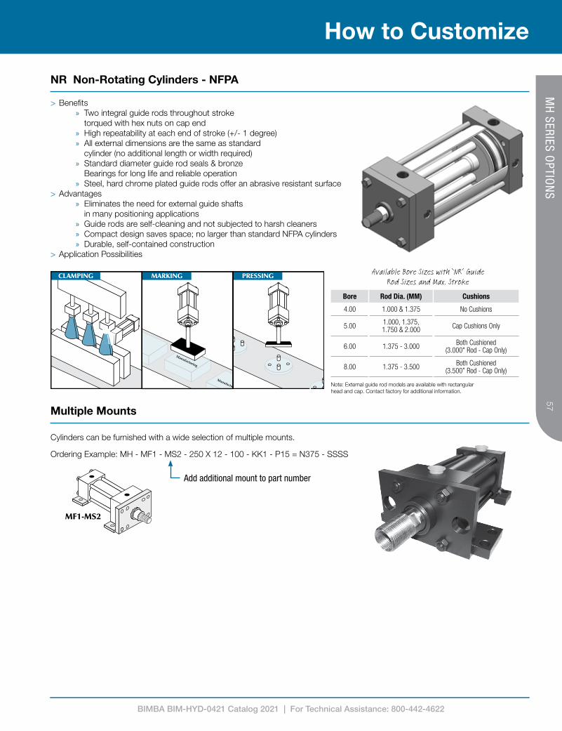
BIMBA BIM-HYD-0421 Catalog 2021 | For Technical Assistance: 800-442-4622
5757
How to Customize
NR Non-Rotating Cylinders - NFPA
MH
SERIES OPTIO
NS
Note: External guide rod models are available with rectangular head and cap. Contact factory for additional information.
Bore Rod Dia. (MM) Cushions
4.00 1.000 & 1.375 No Cushions
5.00 1.000, 1.375, 1.750 & 2.000 Cap Cushions Only
6.00 1.375 - 3.000 Both Cushioned (3.000" Rod - Cap Only)
8.00 1.375 - 3.500 Both Cushioned (3.500” Rod - Cap Only)
> Benefits » Two integral guide rods throughout stroke
torqued with hex nuts on cap end » High repeatability at each end of stroke (+/- 1 degree) » All external dimensions are the same as standard
cylinder (no additional length or width required) » Standard diameter guide rod seals & bronze
Bearings for long life and reliable operation » Steel, hard chrome plated guide rods offer an abrasive resistant surface
> Advantages » Eliminates the need for external guide shafts
in many positioning applications » Guide rods are self-cleaning and not subjected to harsh cleaners » Compact design saves space; no larger than standard NFPA cylinders » Durable, self-contained construction
> Application Possibilities
Available Bore Sizes with ‘NR’ Guide Rod Sizes and Max. Stroke
Add additional mount to part number
Cylinders can be furnished with a wide selection of multiple mounts.
Ordering Example: MH - MF1 - MS2 - 250 X 12 - 100 - KK1 - P15 = N375 - SSSS
Multiple Mounts

BIMBA BIM-HYD-0421 Catalog 2021 | For Technical Assistance: 800-442-4622
58
How to Customize
Port Options
Cylinders can be furnished with NPTF or SAE O-Ring Boss (SAEJ514) ports at no-charge.
Cylinders can be furnished with BSPP or BSPT for additional cost.
BSPT = British Standard Pipe Taper
British Standard Pipe Taper (BSPT) threads have the same taper as American NPT tapered threads, but use a 55° Whitworth thread form and different diameters.
(Not interchangeable with NPT)
BSPP = British Standard Pipe Parallel
British Standard Pipe Parallel (BSPP), also referred to as BSP “Straight” Thread.
(Not interchangeable with NPT)
RBB = Our standard floating rod bushing design is used in conjunction with solid SAE 660 bronze material. Material specifications: 20,000 PSI compressive strength.
Some customers prefer to use bronze rod bushings. Most common uses are in water hydraulic applications.
Specials: Bimba can provide special length rod bushings; contact your local distributor for details.
SSR = Cylinders can be furnished with hard chrome plated stainless steel piston rods.
100,000 min. yield (rods up to 5.00)
75,000 min. yield (5.500 rod)
MH
SERIES OPTIO
NS
RBB Solid Bronze Rod Bushing
Note: Since the mechanical properties of bronze is much lower than cast iron, bronze rod bushings typically do not provide the same long life that our standard PTFE coated cast iron rod bushings provide.
SSR 17-4 Stainless Steel Hard Chrome Plated Piston Rod
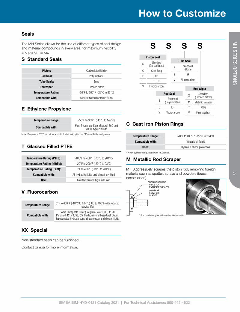
BIMBA BIM-HYD-0421 Catalog 2021 | For Technical Assistance: 800-442-4622
5959
How to Customize
Seals
MH
SERIES OPTIO
NS
Piston: Carboxilated Nitrile
Rod Seal: Polyurethane
Tube Seals: Buna
Rod Wiper: Flocked Nitrile
Temperature Rating: -20°F to 200°F (-29°C to 93°C)
Compatible with: Mineral based hydraulic fluids
Temperature Range: -50°F to 300°F (-45°C to 149°C)
Compatible with: Most Phosphate Ester (Skydrol 500 and 7000, type 2) fluids
Temperature Range: -20°F to 400°F* (-29°C to 204°C)
Compatible with: Virtually all fluids
Uses: Hydraulic shock protection
Temperature Rating (PTFE): -100°F to 400°F (-73°C to 204°C)
Temperature Rating (Nitrile): -20°F to 200°F (-29°C to 93°C)
Temperature Rating (FKM): 0°F to 400°F (-18°C to 204°C)
Compatible with: All hydraulic fluids and almost any fluid
Use: Low friction and high side load
Temperature Range: 0°F to 400°F (-18°C to 204°C) (Up to 400°F with reduced service life)
Compatible with:Some Phosphate Ester (Houghto-Safe 1000, 1120;
Pyrogard 42, 43, 53, 55) fluids; mineral based petroleum, halogenated hydrocarbons, silicate ester and diester fluids
Non-standard seals can be furnished.
Contact Bimba for more information.
The MH Series allows for the use of different types of seal design and material compounds in every area, for maximum flexibility and performance.
S Standard Seals
E Ethylene Propylene
Note: Requires a PTFE rod wiper and L011 lubricant option for EP compilable seal grease.
C Cast Iron Piston Rings
* When cylinder is equipped with FKM seals.
T Glassed Filled PTFE
*
* Standard energizer will match cylinder seals.
M = Aggressively scrapes the piston rod, removing foreign material such as spatter, sprays and powders (brass construction).
M Metallic Rod Scraper
V Fluorocarbon
XX Special
S S S SPiston Seal
S Standard (Carboxilated)
C Cast-Ring
E EP
T PTFE
V Fluorocarbon
Rod Seal
S Standard (Polyurethane)
E EP
V Fluorocarbon
Tube Seal
S Standard (Buna)
E EP
V Fluorocarbon
Rod Wiper
S Standard (Flocked Nitrile)
M Metallic Scraper
T PTFE
V Fluorocarbon
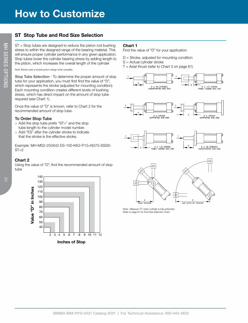
BIMBA BIM-HYD-0421 Catalog 2021 | For Technical Assistance: 800-442-4622
60
How to Customize
ST Stop Tube and Rod Size Selection
Chart 1Find the value of “D” for your application
D = Stroke, adjusted for mounting condition S = Actual cylinder stroke T = Axial thrust (refer to Chart 3 on page 61)
Note: Measure “D” when cylinder is fully extended.Refer to page 61 for Rod Size Selection Chart.
Chart 2Using the value of “D”, find the recommended amount of stop tube
140
130
120
110
100
90
80
70
60
50
40
2 3 4 5 6 7 8 9 10 11 12
Inches of Stop
Val
ue “
D”
in In
ches
ST = Stop tubes are designed to reduce the piston rod bushing stress to within the designed range of the bearing material. This will ensure proper cylinder performance in any given application. Stop tubes lower the cylinder bearing stress by adding length to the piston, which increases the overall length of the cylinder
Note: Bimba uses a double piston design when possible.
Stop Tube Selection - To determine the proper amount of stop tube for your application, you must first find the value of “D”, which represents the stroke (adjusted for mounting condition). Each mounting condition creates different levels of bushing stress, which has direct impact on the amount of stop tube required (see Chart 1).
Once the value of “D” is known, refer to Chart 2 for the recommended amount of stop tube.
To Order Stop Tube > Add the stop tube prefix “ST=” and the stop tube length to the cylinder model number.
> Add “ES” after the cylinder stroke to indicate that the stroke is the effective stroke.
Example: MH-MS2-250X42 ES-100-KK2-P15=N375-SSSS-ST=2
MH
SERIES OPTIO
NS
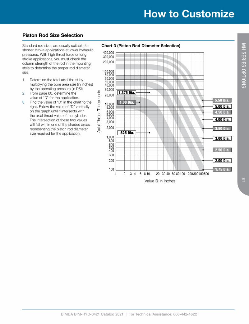
BIMBA BIM-HYD-0421 Catalog 2021 | For Technical Assistance: 800-442-4622
6161
How to Customize
Piston Rod Size Selection
MH
SERIES OPTIO
NS
Standard rod sizes are usually suitable for shorter stroke applications at lower hydraulic pressures. With high thrust force or long stroke applications, you must check the column strength of the rod in the mounting style to determine the proper rod diameter size.
1. Determine the total axial thrust by multiplying the bore area size (in inches) by the operating pressure (in PSI).
2. From page 60, determine the value of “D” for the application.
3. Find the value of “D” in the chart to the right. Follow the value of “D” vertically on the graph until it intersects with the axial thrust value of the cylinder. The intersection of these two values will fall within one of the shaded areas representing the piston rod diameter size required for the application.
Chart 3 (Piston Rod Diameter Selection)
Value D in Inches
Axi
al T
hrus
t T in
pou
nds
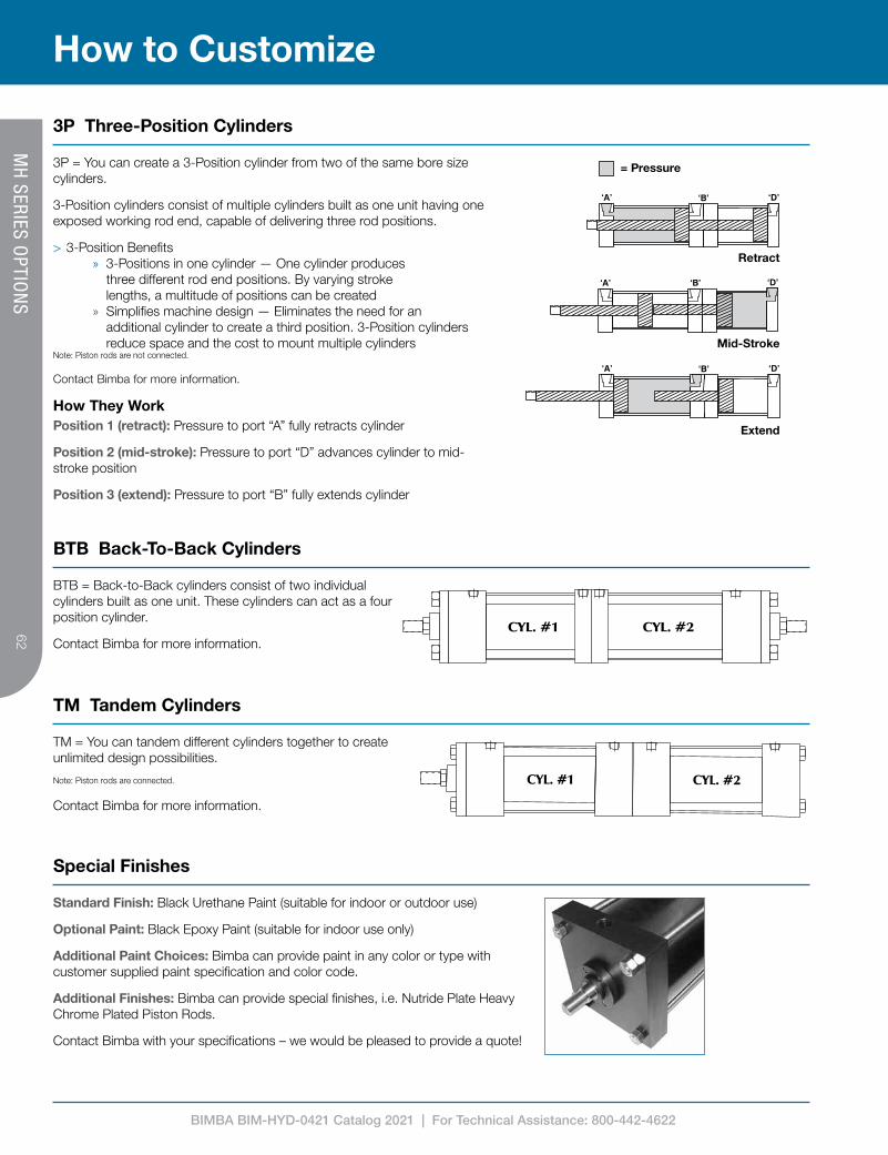
BIMBA BIM-HYD-0421 Catalog 2021 | For Technical Assistance: 800-442-4622
62
How to Customize
3P Three-Position Cylinders
3P = You can create a 3-Position cylinder from two of the same bore size cylinders.
3-Position cylinders consist of multiple cylinders built as one unit having one exposed working rod end, capable of delivering three rod positions.
> 3-Position Benefits » 3-Positions in one cylinder — One cylinder produces
three different rod end positions. By varying stroke lengths, a multitude of positions can be created
» Simplifies machine design — Eliminates the need for an additional cylinder to create a third position. 3-Position cylinders reduce space and the cost to mount multiple cylinders
Note: Piston rods are not connected.
Contact Bimba for more information.
Position 1 (retract): Pressure to port “A” fully retracts cylinder
Position 2 (mid-stroke): Pressure to port “D” advances cylinder to mid-stroke position
Position 3 (extend): Pressure to port “B” fully extends cylinder
How They Work
= Pressure
Retract
Mid-Stroke
Extend
BTB = Back-to-Back cylinders consist of two individual cylinders built as one unit. These cylinders can act as a four position cylinder.
Contact Bimba for more information.
TM = You can tandem different cylinders together to create unlimited design possibilities.
Note: Piston rods are connected.
Contact Bimba for more information.
Standard Finish: Black Urethane Paint (suitable for indoor or outdoor use)
Optional Paint: Black Epoxy Paint (suitable for indoor use only)
Additional Paint Choices: Bimba can provide paint in any color or type with customer supplied paint specification and color code.
Additional Finishes: Bimba can provide special finishes, i.e. Nutride Plate Heavy Chrome Plated Piston Rods.
Contact Bimba with your specifications – we would be pleased to provide a quote!
MH
SERIES OPTIO
NS
BTB Back-To-Back Cylinders
TM Tandem Cylinders
Special Finishes