Embed Size (px)
Citation preview
General rights Copyright and moral rights for the publications made accessible in the public portal are retained by the authors and/or other copyright owners and it is a condition of accessing publications that users recognise and abide by the legal requirements associated with these rights.
Users may download and print one copy of any publication from the public portal for the purpose of private study or research.
You may not further distribute the material or use it for any profit-making activity or commercial gain
You may freely distribute the URL identifying the publication in the public portal If you believe that this document breaches copyright please contact us providing details, and we will remove access to the work immediately and investigate your claim.
Downloaded from orbit.dtu.dk on: Jun 24, 2020
MgO as a non-pyrolyzable pore former in porous membrane supports
Haugen, A. B.; Geffroy, A.; Kaiser, Andreas; Gil, Vanesa
Published in:Journal of the European Ceramic Society
Link to article, DOI:10.1016/j.jeurceramsoc.2018.02.039
Publication date:2018
Document VersionPeer reviewed version
Link back to DTU Orbit
Citation (APA):Haugen, A. B., Geffroy, A., Kaiser, A., & Gil, V. (2018). MgO as a non-pyrolyzable pore former in porousmembrane supports. Journal of the European Ceramic Society, 38(9), 3279-3285.https://doi.org/10.1016/j.jeurceramsoc.2018.02.039

MgO as a non-pyrolyzable pore former in porous membrane supports
A.B. Haugen1*, A. Geffroy2**, A. Kaiser1 and V. Gil1***
1 Department of Energy Conversion and Storage, Technical University of Denmark,
Frederiksborgvej 399, DK-4000 Roskilde, Denmark 2 Department of Materials, Polytech Nantes, Rue Christian Pauc CS 50609, 44306 Nantes Cedex
3, France
* Corresponding author. E-mail: [email protected], phone: +45 21 56 09 19
** This work was performed during the author’s internship at the Technical University of Denmark
*** Currently at: Fundación Agencia Aragonesa para la Investigación y Desarrollo (ARAID)-
Tecnologías del Hidrógeno en Aragón, Spain
Abstract
The gas permeability of Y0.03Zr0.97O2 (3Y-TZP) porous supports from thermoplastic feedstocks has
been improved by adding MgO as a non-pyrolyzable pore former. Common pyrolyzable pore
formers such as graphite often produce tortuous and narrow pore channels with low gas
permeability, limiting the performance of oxygen transport membranes or other membranes relying
on gas transport to the active membrane surface. Thermoplastic feedstocks for extrusion of tubular
3Y-TZP supports were prepared with four different amounts of pyrolyzable pore formers and/or
MgO as non-pyrolyzable pore former. The MgO was removed after sintering by leaching in acetic
acid. With this technique we obtained porosities above 70 vol% and gas permeabilities above 3∙10-
14 m2. Compared to samples with only pyrolyzable pore formers, the non-pyrolyzable pore former
increases the gas permeability and reduces the tortuosity.
Graphical abstract
1

Keywords: Oxygen transport membrane; Y-TZP; porous ceramic; thermoplastic shaping; gas
permeability
1 Introduction
Porous ceramic supports are key components in asymmetric, inorganic membranes.1, 2 Oxygen
transport membranes for example, only reach sufficiently high performance when used as thin,
dense membranes supported on thicker, gas-permeable macroporous supports.3, 4 Their fabrication
should be suitable for large volumes, also in non-planar shapes such as tubes.1, 3 One option is
extrusion of thermoplastic feedstocks containing pore formers. Thermoplastic feedstocks provide
high green body strength even for thin-walled (0.5-1 mm) structures, and although they require slow
debinding, the drying of fragile tubes as in water-based extrusion can be avoided.5 Porosity in the
thin-walled support tubes can be produced from coarse staring powders or from pore formers. For
the preparation of asymmetric membranes the latter is preferred, as it allows using finer ceramic
powder with higher shrinkage during sintering, suitable for co-sintering of the support layer with a
dense membrane layer.6, 7
The porous support’s gas permeability (k, the Darcy gas permeability coefficient8) depends on the
volume fraction of porosity (ϕ), the pore diameter (Dp) and the tortuosity factor (𝛕𝛕), and can be
expressed as:
𝑘𝑘 = 𝜙𝜙𝐷𝐷𝑝𝑝2
16𝜏𝜏 (1)
where the tortuosity factor takes the value 2 for the ideal case with parallel pore channels (capillary
permeability).9 Porous supports for oxygen transport membranes should have gas permeability in
the range of 10-14 m2 to avoid limitation in the gas supply to the membrane surface.4 Eqn. 1 then
suggests for example a combination of pore channels wider than 1 µm and porosity above 40 % as
the targets for reaching 10-14 m2 permeability (assuming a tortuosity factor of 2).
Pyrolyzable pore formers - such as graphite, starches and polymers – usually burn off or decompose
at temperatures (400-700 °C) that are relatively low compared to the final sintering temperature
(typically >1200 °C). A consequence of this low-temperature removal is significant densification
after the pores are formed, such that they get isolated and cannot contribute to gas permeation.
Furthermore, spherical pore formers are often chosen to avoid shear forces aligning them
perpendicular to the desired direction of gas flow. But this also makes the connected pore channel
2

through the material more dependent on the contact area of the spherical pore former particles than
the actual size of the pore former particles. Pyrolyzable pore formers therefore often give a pore
structure with a high volume of large, spherical pores, but with narrow, tortuous channels that form
bottlenecks between the pores.10 Our previous work7 with the pyrolyzable pore formers PMMA and
graphite in thermoplastic feedstocks for membrane support also showed this. Approximately 50
vol% of pore former within the dry content provided sufficient porosity (40 %), but more than 60
vol% pore formers were required before the permittivity target (10-14 m2) was reached, since the
quite spherical pores were poorly connected and the pore size not efficiently enlarged by increasing
the pore former content.7 The resulting high porosity (>60 %) limits the samples’ mechanical
strength. A way of improving pore connections, such that the pore size can be increased more
efficiently at lower pore former content, is therefore desired.
A less studied alternative to pyrolyzable pore formers are non-pyrolyzable pore formers. One
example is reduction of NiO to Ni in solid oxide fuel cell anode supports,11 such that porosity is
generated after sintering from the volume decrease associated with the reduction. Additional
porosity has also been created by leaching out the remaining Ni with acid.12, 13 Some studies of
porosity from oxides leached with acid have also been reported: MgO from Ce0.8Gd0.2O,14 and ZnO
from Y0.08Zr0.92O2.15
In this work, we have investigated whether oxide leaching was compatible with thermoplastic
feedstocks previously developed7 for extrusion of Y0.03Zr0.97O2 (3YSZ or 3Y-TZP) porous oxygen
transport membrane supports, and to what extent the non-pyrolyzable pore formers could improve
the gas permeability of the pore network generated by pyrolyzable pore formers. We chose MgO as
the non-pyrolyzable pore former due to its low cost and toxicity, solubility in water, and high
reactivity towards weak acids also as an oxide. We studied four feedstocks with different amounts
of pyrolyzable pore formers and/or MgO as non-pyrolyzable pore former, sintered in the
temperature range (1250-1400 °C) which is relevant for co-sintering of the 3Y-TZP supports with
the thin layer of the oxygen transport membrane.
2 Experimental
2.1 Porous support processing
3

The composition of the thermoplastic feedstocks for porous 3Y-TZP supports are listed in Table 1.
A test feedstock (Y-TZP-MgO-test) was first made to check the compatibility of MgO with the
thermoplastic feedstocks previously developed7 for only 3Y-TZP (Y-TZP-test). For these test
feedstocks, the Y-TZP powder was TZ-3Y-E (d50 = 0.04 µm, Tosoh, Japan) and the MgO powder
Product #12R-0801 (Inframat, USA) calcined for 10 h at 1000 °C (d50 = 0.15 µm). Based on the
results from the test feedstocks, the ceramic powders for the further study were changed to TZ-3YS-
E (d50 = 0.09 µm, Tosoh, Japan) and MgO from MC10-200 (Martin Marietta Magnesia Specialties
LCC, USA) milled to d50 = 1.8 µm. Stearic acid (Sigma-Aldrich, USA) was used as a surfactant, in
an amount equivalent to 1.5 monolayer coverage of all 3Y-TZP and MgO.16, 17 The pyrolyzable
pore formers were graphite (d50 = 18 µm, FormulaBT SLA1518, Superior Graphite, USA) and
PMMA (d50 = 9 µm, MR-10G, Esprix, USA), in the volume ratio 2:1. The above mentioned
chemicals constituted the dry content, which together made up 65 vol% of the feedstocks. The
remaining 35 vol% were the thermoplastic binders ethylene-vinyl acetate copolymer (Elvax© 250,
DuPont, USA) and paraffin wax (melting point 53-57 °C, Sigma-Aldrich, USA), in the volume ratio
2:1.
Table 1. Composition of the thermoplastic feedstocks for studying MgO as non-pyrolyzable pore
former. The vol% refer to the composition within the solid content.
Feedstock code Vol% MgO as pore former
Vol% pyrolyzable pore formers
Vol% 3Y-TZP
Total vol% pore formers
Y-TZP-test/ 0m-62p-38z 0 62 38 62
Y-TZP-MgO-test/ 13m-62p-25z 13 62 25 75
20m-38p-42z 20 38 42 58
33m-0p-67z 33 0 67 33
Thermoplastic feedstocks with a total volume of 55 ml were mixed and compounded at 110-115 °C
(Kneader 50N, Brabender, Germany). Discs of 24 mm diameter and 1-2 mm thickness were shaped
by warm pressing and cutting at 100 °C. The samples were debinded in air with a slow heating rate
(10 °C/h) and with isothermal holds (2 h) at 250, 400 and 650 °C or 200, 300, 350 and 650 °C (no
4

difference observed), then ramped with 30 °C/h to the sintering temperature (1250–1400°C, 2 h)
and finally cooled at 100 °C/h to room temperature.
Leaching in acetic acid (Sigma Aldrich, USA) and distilled water was studied with the Y-TZP-
MgO-test feedstock sintered at 1300 °C. Acid strength, volume and temperature was varied, and the
time for complete leaching observed. Complete leaching was defined as removal of the mass of
MgO added to the sample minus the MgO that dissolves in the 3Y-TZP structure18 and therefore
cannot be (as easily) leached out. Based on this leaching study, the chosen procedure for further
work was to soak the samples in 33 ml 60 % acetic acid per g sample until complete leaching was
obtained. This procedure required 30 h for samples of feedstock Y-TZP-MgO-test and 13m-62p-
25z, while for 20m-38p-42z the required leaching time was dependent on the sintering temperature:
30 h + 70 h for 1250 °C-samples, 30 + 120 h for 1300 °C-samples, and 120 + 120 h for 1400 °C-
samples. For samples from feedstock 33m-0p-67z, 30 h of the conventional 60% acetic acid at room
temperature was followed by 70 h in 37 % hydrochloric acid (VWR Chemicals, USA) and 300 h in
100 % acetic acid at 50 °C. The samples were rinsed in distilled water and dried between each
leaching step.
The samples are named according to the scheme: “vol% MgO” – “vol% pyrolyzable pore formers”
– “vol% 3Y-TZP” - “sintering temperature (in °C)” - “leaching state (L for leached, UL for un-
leached)”. For example, 13m-62p-25z-1300-UL contains 13 % MgO, 62% pyrolyzable pore
formers (graphite and PMMA) and 25 vol% 3Y-TZP within the solid content, has been sintered at
1300 °C, and has not been leached.
2.2 Characterization
Debinding, densification and phase composition were studied with thermogravimetry (STA
409PC/PG, Netzsch, Germany), dilatometry (DIL 402, Netzsch, Germany) and x-ray diffraction
(D8, Bruker, USA). Mercury porosimetry (Poremaster© GT, Quantachrome Instruments, USA) was
used to measure open porosity and pore size distribution of sintered samples. The microstructure of
polished sample cross-sections was studied by SEM (TM 3000, Hitachi, Japan) and EDS (SDD,
Bruker, USA). The flow of N2 through the samples under a pressure gradient of 200 kPa at room
temperature was used to measure the Darcy gas permeability coefficient, k.8
5
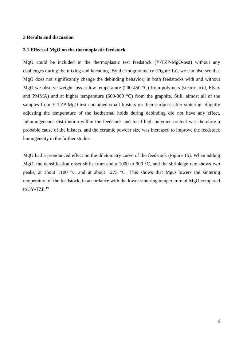
3 Results and discussion
3.1 Effect of MgO on the thermoplastic feedstock
MgO could be included in the thermoplastic test feedstock (Y-TZP-MgO-test) without any
challenges during the mixing and kneading. By thermogravimetry (Figure 1a), we can also see that
MgO does not significantly change the debinding behavior; in both feedstocks with and without
MgO we observe weight loss at low temperature (200-450 °C) from polymers (stearic acid, Elvax
and PMMA) and at higher temperature (600-800 °C) from the graphite. Still, almost all of the
samples from Y-TZP-MgO-test contained small blisters on their surfaces after sintering. Slightly
adjusting the temperature of the isothermal holds during debinding did not have any effect.
Inhomogeneous distribution within the feedstock and local high polymer content was therefore a
probable cause of the blisters, and the ceramic powder size was increased to improve the feedstock
homogeneity in the further studies.
MgO had a pronounced effect on the dilatometry curve of the feedstock (Figure 1b). When adding
MgO, the densification onset shifts from about 1000 to 900 °C, and the shrinkage rate shows two
peaks, at about 1100 °C and at about 1275 °C. This shows that MgO lowers the sintering
temperature of the feedstock, in accordance with the lower sintering temperature of MgO compared
to 3Y-TZP.19
6

Figure 1. a) Thermogravimetrical analysis (TGA), and b) dilatometry of test feedstocks for porous
3Y-TZP supports with MgO as a non-pyrolyzable pore former. [1 column width]
Leaching studies on Y-TZP-MgO-test sintered at 1300 °C showed that acetic acid is a suitable
leaching agent. Complete leaching was observed after removal of 86 wt% of the MgO. Using 133
ml acid per gram sample lead to complete leaching after 10-30 h with 60 % acetic acid (Figure 2a).
For short leaching times, and especially for high concentration of acetic acid, the completeness of
leaching is negative, meaning that the sample gained weight during the leaching. This can be
explained by formation of solid magnesium acetate. This acetate can be removed by soaking in
water, but the shorter the leaching time, the more challenging is the removal from inside the porous
network. Figure 2b) shows that the amount of acid could be reduced to 33 ml/g without affecting
the completeness of leaching after 30 h. Finally, Figure 2c) shows that increasing the temperature
reduces the time required for complete leaching; at 50 °C with 133 ml/g it only takes 2 hours to
complete the leaching. This is similar to observations by Wang et al.14 on leaching of MgO from
Ce0.8Gd0.2O2. Based on the leaching study, all further leaching was performed with 33 ml of 60 %
acid per sample. Since complete leaching was observed after 30 h without heating, the leaching was
performed at room temperature in order to simplify the setup. Using 25 % rather than 60 % might
7

be advantageous for a large-scale leaching of porous supports, since it lowers the hazard
classification of the acid from “corrosive” to “irritant”. Leaching in water did not result in any
measurable weight loss, not even using hot water (up to 100 °C) combined with very long time (up
to 200 h).
Figure 2. Leaching of MgO from 3Y-TZP using acetic acid in a) different concentrations (at room
temperature, 133 ml/g) b) different amounts (60 %, room temperature) and c) different temperatures
(60%, 133 ml/g). [Full page width]
XRD on sintered samples (Figure 3) shows that MgO affects the crystallographic structure of the
3Y-TZP porous supports. All samples have a polymorph of zirconia as their main phase. Before
leaching, MgO is present as a separate phase in the Y-TZP-MgO samples, but this MgO phase is
completely removed by the leaching. Still, in Y-TZP-MgO-test-1250-L there are extra peaks
compared to Y-TZP-test-1250 at either side of the main reflection at 2θ = 30°. These peaks can be
indexed to monoclinic zirconia. Upon increasing sintering temperature the Y-TZP-test samples
remain unaffected while the structure of the Y-TZP-MgO-test samples changes: the zirconia
reflections (e.g. at 2θ = 30°, 35°, 51°, 60° and 75°) transform from doublets to singlets, indicating a
transition from monoclinic and tetragonal to cubic zirconia.
3Y-TZP is used as the membrane support in this work since it offers high toughness as well as
chemical and thermal compatibility with many oxygen transport membrane materials. This
toughness originates from a transition from monoclinic to a metastable tetragonal phase, which is
maximized at 3 mol% Y doping in zirconia.20 It is known that also Mg, up to 15-20 mol%, can
dissolve in the zirconia structure.18 The 14 wt% non-leachable MgO in our work corresponds to 13
mol% of MgO forming a solid solution with Y-TZP, hence in good correlation with the previous
reports.18 Mg can stabilize the tetragonal phase in zirconia,20 but Mg in Y-doped zirconia can
8

promote a cubic phase instead.21 This is also what we observed here, with the change from
tetragonal to monoclinic and cubic phases when MgO is introduced. Monoclinic and cubic phases
of zirconia with 3 mol% Y have lower toughness than 3Y-TZP,20 hence our approach with MgO as
the non-pyrolyzable pore former will lower the toughness of the porous supports. On the other
hand, at a given sintering temperature the matrix structure of 3Y-TZP doped with MgO densifies
more than undoped 3Y-TZP (Figure 1b), and its higher density could counteract its intrinsic lower
toughness. The aim of this work was to check the compatibility of non-pyrolyzable pore formers in
the thermoplastic feedstocks and their effect on the pore structure and the gas permeability, but
further development of 3Y-TZP porous supports with MgO as the non-pyrolyzable pore former
should include a thorough investigation of mechanical properties. Alternatively, MgO could be
added to zirconia to instead of to 3Y-TZP, which upon meticulous control of processing
temperature and grain size can provide Mg-stabilized zirconia. 20, 21
Figure 3. XRD patterns of 3Y-TZP porous supports with MgO as non-pyrolyzable pore former.
The reflections from MgO are assigned according to PDF card 89-7746. All other peaks are
tetragonal (48-0224), monoclinic (37-1484) or cubic (30-1468) zirconia. [1 column width]
3.2 Microstructure of 3Y-TZP porous supports with MgO as pore former
After the initial test feedstocks, four feedstocks with varying amounts of MgO and pyrolyzable pore
formers were made (compositions in Table 1). Properties of all these samples are listed in Table
A.1.
9

All thermoplastic feedstocks could be kneaded into a homogenous feedstock and sintered into
defect-free samples. This demonstrates both that 35 vol% polymers was suitable for shaping all
compositions, and that changing to coarser 3Y-TZP and MgO powders improved the feedstock
homogeneity (compared to the test feedstocks) such that blisters were avoided. The total linear
shrinkage during sintering increased slightly with addition of MgO, but was mostly affected by the
sintering temperature and the amount of pyrolyzable pore former (Table A.1).
Figure 4 shows SEM micrographs after sintering at 1300 °C, before and after leaching. MgO are the
dark grey spots and pores from the pyrolyzable pore formers are black. The sample without MgO
(0m-62p-38z-1300, Figure 4a) contains large pores (5-20 µm) from the pyrolyzable pore formers,
and small pores (<1 µm) between the grains within the 3Y-TZP matrix. When MgO is introduced
(Figures 4b-d), the smaller pores disappear and the matrix phase appears denser, while the size and
shape of pores from pyrolyzable pore formers seem to be unaffected. MgO is present as evenly
distributed 1-5 µm particles, as expected from their particle size (d50 = 1.8 µm). The shape and size
distribution of MgO can be clearly seen in sample 33m-0p-67z-UL (Figure 4d), since this sample
does not have pyrolyzable pore formers. Complete leaching was obtained in 13m-62p-25z and 20m-
38p-42z, which is reflected in the lack of MgO after leaching (Figure 4e-f). In 33m-0p-67z (Figure
4g) on the other hand, there is no visible change in the MgO distribution and amount; only 0.12,
0.02 and 0.01 in completeness of leaching was obtained at 1250, 1300 and 1400 °C, respectively
(Table A.1). The 3Y-TZP matrix phase remains intact during the leaching.
Figure 4. Microstructural change of 3Y-TZP porous supports with increasing content of MgO as
non-pyrolyzable pore former (sintering temperature 1300 °C), before (top) and after (bottom)
leaching. [1.5 column width]
EDS maps (Figure 5) show more clearly how the leaching affects the distribution of MgO and
porosity. Like in Figure 4, the large MgO particles in 13m-62p-25z and 20m-38p-42z are
10

completely removed after leaching (Figure 5d-e), but with about 4 at% Mg left randomly distributed
within the 3Y-TZP matrix (Table A.1). These 4% corresponds to the 14 wt% of the MgO that could
not be leached out (Section 3.1). The EDS map for 33m-0p-67z after leaching (Figure 5f) is taken
close to the surface of the sample (at the top in the picture). Here, we can clearly see that only the
outer few micrometers have been leached. Similar maps of 33m-0p-67z sintered at 1250 °C show a
leaching depth of ~20 µm, while after sintering at 1400 °C only MgO particles directly at the
surface were leached out. Furthermore, the amount of Mg observed by EDS after leaching is 2-4
at% Mg in 13m-62p-25z and 20m-38p-42z, while it remains at ~20 at% in 33m-0p-67z (Table A.1).
This indicates challenges in leaching samples with no or low pre-existing porosity, where the
leaching depends on the acid “digging” its way into the sample through narrow channels. The work
on 33m-0p-67z was therefore discontinued. Still, this knowledge is useful if the supports are to be
co-sintered with e.g. oxygen transport membrane layers. The membrane must then be acid-resistant
(e.g. based on Y-TZP or Ce0.8Gd0.2O2), or the leaching must be performed on a pre-sintered, bare
support before application and sintering of the membrane layer. Given how dependent the acetic
acid penetration depth is on the support’s porosity (33m-0p-67z), carefully adjusted leaching
parameters could also allow e.g. leaching only the inside of tubular supports while a membrane
layer on the outside remains undamaged.
Figure 5. EDS maps visualizing the distribution of Mg (green), Zr (red) and pores (black) in 3Y-
TZP supports (sintering temperature 1300 °C) with increasing amount of MgO non-pyrolyzable
pore former. The top row samples are before and bottom row after leaching. [1.5 column width]
3.3 Porosity and pore size of 3Y-TZP porous support with MgO as pore former
Open porosity (vol%) and mean pore size (pore channel bottleneck) was measured with mercury
porosimetry to quantify the effect of adding MgO as a pore former to the 3Y-TZP supports. The
11

porosity increases markedly upon leaching for all samples, and above 70 vol% is reached in 13m-
62p-25z after leaching (Figure 6a). The measured open porosity is generally in close correlation
with the porosity expected from the amount of pore formers (Table 1). The porosity values also
show that MgO densifies the Y-TZP supports. For example, 13m-62p-25z has ~10 % lower porosity
before leaching than 0m-62p-38z, although they both have the same amount of non-leachable pore
formers. The mean pore size (Figure 6b) also increases with leaching, and the largest mean pore
size (1.6 µm) is again found in 13m-62p-25z. Higher sintering temperature causes the porosity to
slightly decrease and the pore size to slightly increase. The same trend was previously observed
with thermoplastic feedstocks,7 and is related to the higher densification of the 3Y-TZP matrix,
which both removes the small pores within the Y-TZP matrix and widens the pore channels.
Figure 7 reveals the effect of MgO as a non-pyrolyzable pore former on the cumulative pore volume
distributions. Leaching of MgO increases the volume of large pore channels (2-10 µm) relative to
the volume of very small pore channels (0.2-1 µm), while the median pore size remains less
affected (Figure 7a). With increased sintering temperatures the entire pore size distribution shifts
towards higher values (Figure 7b). Remarkably, the accumulated pore volume of 2-10 µm sized
pores is increased from about 2.5 % at a sintering temperature of 1250 °C to about 25 % at 1400 °C.
Figure 6. Open porosity (vol%) (a) and mean pore size (d50) (b) vs. sintering temperature in the 3Y-
TZP porous supports made with MgO as a non-pyrolyzable pore former. The legends apply to both
plots. [1 column width]
12

Figure 7. Effect of MgO as non-pyrolyzable pore former on cumulative pore volume of 3Y-TZP
porous supports (a), and effect of sintering temperature (b). [1 column width]
3.4 Gas permeability of 3Y-TZP porous supports with MgO as pore former
Figure 8 shows how MgO as a non-pyrolyzable pore former affects the gas permeability of the
porous 3Y-TZP supports. Leaching increases the gas permeability in all samples, and with the
highest amount of pyrolyzable and non-pyrolyzable pore formers (13m-62p-25z), the permeability
after leaching is above 3∙10-14 m2. This is almost twice as high as the corresponding sample (0m-
62p-38z) without pyrolyzable pore formers. The lower permeability of 13m-62p-25z-UL compared
to 0m-62p-38z is as expected from the higher sintering and thereby lower porosity of the 3Y-TZP
supports upon addition of MgO. When the amount of MgO as pore former is increased, but the total
amount of pyrolyzable pore formers is reduced (20m-38p-42z) the gas permeability also decreases,
13

but is still around 1∙10-14 m2 after leaching. Finally, we can also see that the gas permeabilities of
leached samples are relatively unaffected by the sintering temperature within the studied range
(1250-1400 °C).
To assess the effect of the non-pyrolyzable pore formers, we should also consider their tortuosity.
Eqn. 1 makes it possible to estimate the tortuosity factor based on the measured permeability,
porosity and mean pore size. Figure 9 shows the calculated tortuosity factor for all samples. As
expected, the leached samples have a lower tortuosity than the unleached, but we can also see a
trend of lower tortuosity with increasing content of non-pyrolyzable pore formers. The latter is not
only an effect of a higher total content of pore formers and a higher porosity, since this is lower in
the samples with 20 % MgO (20m-38p-42z) than the other compositions. The low tortuosity factors
demonstrate that the leached samples with MgO as non-pyrolyzable pore former are significantly
closer to having cylindrical, straight pores (described by a tortuosity factor of 2), compared to both
the unleached samples and the samples without MgO. This again indicates that we have succeeded
in improving the pore connectivity as we aimed for.
Figure 8. Gas permeability of the 3Y-TZP porous supports before and after leaching. [1 column
width]
14
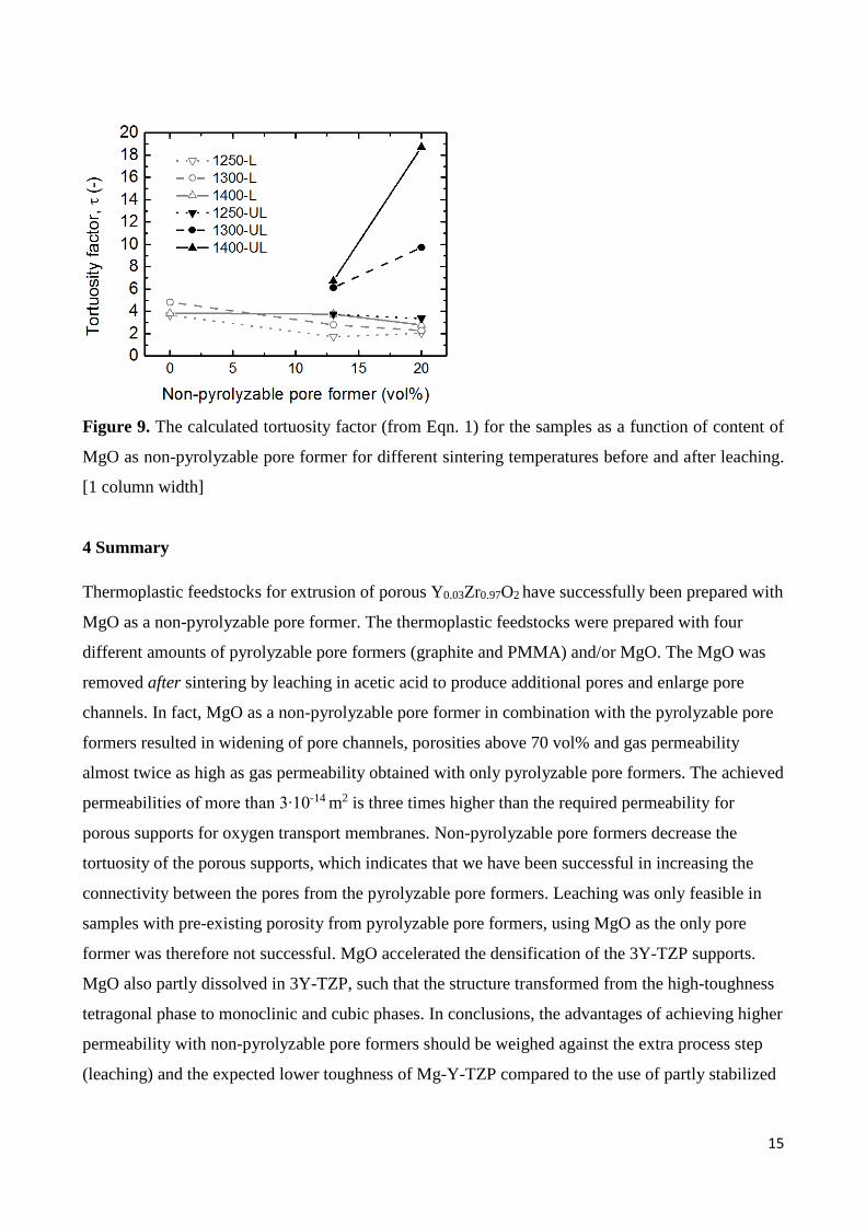
Figure 9. The calculated tortuosity factor (from Eqn. 1) for the samples as a function of content of
MgO as non-pyrolyzable pore former for different sintering temperatures before and after leaching.
[1 column width]
4 Summary
Thermoplastic feedstocks for extrusion of porous Y0.03Zr0.97O2 have successfully been prepared with
MgO as a non-pyrolyzable pore former. The thermoplastic feedstocks were prepared with four
different amounts of pyrolyzable pore formers (graphite and PMMA) and/or MgO. The MgO was
removed after sintering by leaching in acetic acid to produce additional pores and enlarge pore
channels. In fact, MgO as a non-pyrolyzable pore former in combination with the pyrolyzable pore
formers resulted in widening of pore channels, porosities above 70 vol% and gas permeability
almost twice as high as gas permeability obtained with only pyrolyzable pore formers. The achieved
permeabilities of more than 3∙10-14 m2 is three times higher than the required permeability for
porous supports for oxygen transport membranes. Non-pyrolyzable pore formers decrease the
tortuosity of the porous supports, which indicates that we have been successful in increasing the
connectivity between the pores from the pyrolyzable pore formers. Leaching was only feasible in
samples with pre-existing porosity from pyrolyzable pore formers, using MgO as the only pore
former was therefore not successful. MgO accelerated the densification of the 3Y-TZP supports.
MgO also partly dissolved in 3Y-TZP, such that the structure transformed from the high-toughness
tetragonal phase to monoclinic and cubic phases. In conclusions, the advantages of achieving higher
permeability with non-pyrolyzable pore formers should be weighed against the extra process step
(leaching) and the expected lower toughness of Mg-Y-TZP compared to the use of partly stabilized
15

3Y-TZP as support material for oxygen transport membranes. Still, this work also opens up for non-
pyrolyzable pore formers other than MgO, or supports other than 3Y-TZP within the same
framework of thermoplastic feedstocks.
Acknowledgements
We thank Pernille Hedemark Nielsen and Jeanette Krambech for assisting with sample preparation
for SEM and mercury porosimetry. Parts of the work has been funded by Energinet.dk through
grant number 12403 “Highly Flexible Energy Production by Oxy-Fired Biomass Gasification”.
16

Appendix A
Table A.1. Results from all samples: Linear shrinkage during sintering, open porosity (ϕ), pore size
(d10, d50 and d90), gas permeability coefficient (k), tortuosity factor calculated from Eqn. 1 (𝛕𝛕), and
amount of Mg measured by EDS.
Sample name
Shrinkage (%)
ϕ (%)
d10
(µm) d50
(µm) d90
(µm) k
(m2) 𝛕𝛕
(-) Mg
(at%) 0m-62p-38z-1250 16 68 1.75 1.23 0.27 1.90E-14 3.7 0m-62p-38z-1300 20 67 1.79 1.33 0.36 1.80E-14 4.8 0m-62p-38z-1400 25 46 1.9 1.54 0.73 1.80E-14 3.8 13m-62p-25z-1250-UL 17 56 1.34 1.03 0.41 1.1E-14 3.7 24 13m-62p-25z-1300-UL 21 53 1.63 1.27 0.50 9.6E-15 6.1 19 13m-62p-25z-1400-UL 25 38 1.77 1.43 0.69 7.2E-15 6.7 20 13m-62p-25z-1250-L 17 74 1.45 1.08 0.53 3.2E-14 1.7 2 13m-62p-25z-1300-L 21 74 13.4 1.40 0.67 3.4E-14 2.8 3 13m-62p-25z-1400-L 25 73 7.12 1.61 0.79 3.2E-14 3.8 4 20m-38p-42z-1250-UL 14 35 0.70 0.54 0.27 1.9E-15 3.4 23 20m-38p-42z-1300-UL 18 29 0.83 0.63 0.33 7.4E-16 9.7 26 20m-38p-42z-1400-UL 20 23 0.89 0.67 0.34 3.5E-16 18.7 23 20m-38p-42z-1250-L 14 62 0.96 0.67 0.39 9.8E-15 2.1 2 20m-38p-42z-1300-L 18 48 1.04 0.82 0.46 9.0E-15 2.3 4 20m-38p-42z-1400-L 20 44 1.22 0.96 0.48 8.9E-15 2.8 4 33m-0p-67z-1250-UL 14 14* 22 33m-0p-67z-1300-UL 15 7* 23 33m-0p-67z-1400-UL 15 5* 22 33m-0p-67z-1250-L 14 16* 22 33m-0p-67z-1300-L 15 7* 22 33m-0p-67z-1400-L 15 5* 22 * weight and dimensions (rather than mercury porosimetry) are used to estimate porosity
References
1 P. Monash, G. Pugazhenthi, and P. Saravanan, “Various fabrication methods of porous
ceramic supports for membrane applications,” Rev. Chem. Eng., 29 [5] 357–383 (2013).
2 D.K. Ramachandran, M. Søgaard, F. Clemens, J. Gurauskis, and A. Kaiser, “Fabrication and
performance of a tubular ceria based oxygen transport membrane on a low cost MgO
support,” Sep. Purif. Technol., 147 422–430 (2015).
3 S. Baumann, W.A. Meulenberg, and H.P. Buchkremer, “Manufacturing strategies for
17
asymmetric ceramic membranes for efficient separation of oxygen from air,” J. Eur. Ceram.
Soc., 33 [7] 1251–1261 (2013).
4 S. Ovtar, J. Gurauskis, A.B. Haugen, C. Chatzichristodoulou, A. Kaiser, and P.V.
Hendriksen, “Oxygen transport properties of tubular Ce0.9Gd0.1O1.95-La0.6Sr0.4FeO3-d
composite asymmetric oxygen permeation membranes supported on magnesium oxide,” J.
Memb. Sci., 523 [August 2016] 576–587 (2017).
5 F. Clemens, “Thermoplastic Extrusion for Ceramic Bodies;” pp. 295–311 in Extrus. Ceram.
Edited by F. Händle. Springer-Verlag, Berlin, 2009.
6 D.K. Ramachandran, M. Søgaard, F. Clemens, B.R. Sudireddy, and A. Kaiser, “Low cost
porous MgO substrates for oxygen transport membranes,” Mater. Lett., 169 254–256 (2016).
7 A.B. Haugen, J. Gurauskis, A. Kaiser, and M. Søgaard, “Graphite and PMMA as pore
formers for thermoplastic extrusion of porous 3Y-TZP oxygen transport membrane
supports,” J. Eur. Ceram. Soc., 37 [3] 1039–1047 (2017).
8 F.W. Altena, H. Heskamp, D. Bargeman, and C.A. Smolders, “Some comments on the
applicability of gas permeation methods to characterize porous membranes based on
improved experimental accuracy and data handling,” J. Memb. Sci., 12 313–322 (1983).
9 T. Ohji and M. Fukushima, “Macro-porous ceramics: processing and properties,” Int. Mater.
Rev., 57 [2] 115–131 (2012).
10 S.F. Corbin and P.S. Apté, “Engineered Porosity via Tape Casting, Lamination and the
Percolation of Pyrolyzable Particulates,” J. Am. Ceram. Soc., 82 [7] 1693–1701 (1999).
11 W.Z. Zhu and S.C. Deevi, “A review on the status of anode materials for solid oxide fuel
cells,” Mater. Sci. Eng. A, 362 [1–2] 228–239 (2003).
12 H. Kim, C. Rosa, M. Boaro, J.M. Vohs, and R.J. Gorte, “Fabrication of Highly Porous Yttria-
Stabilized Zirconia by Acid Leaching Nickel from a Nickel-Yttria-Stabilized Zirconia
Cermet,” J. Am. Ceram. Soc., 85 [6] 1473–1476 (2002).
13 V. Gil and K.K. Hansen, “High Performance Infiltrated Backbones for Cathode-Supported
SOFC’s,” ECS Trans., 64 [2] 41–51 (2014).
18

14 F.-Y. Wang, S. Cheng, B.-Z. Wan, C.-H. Chung, and M.-J. Chen, “A novel method for
preparing highly porous gadolinia-doped-ceria ceramics,” Ceram. Int., 34 [8] 1989–1992
(2008).
15 M.J. Hwang and C.S. Han, “Fabrication of Porous YSZ from ZnO-YSZ Cermet;” pp. 235–
238 in Solid State Phenom. 2007.
16 M. Wegmann, F. Clemens, A. Hendry, and T. Graule, “Dispersion of lanthanoid-coated
barium titanate in a paraffin-based extrusion binder system,” Ceram. Int., 32 [2] 147–156
(2006).
17 M. Salehi, F. Clemens, E.H. Otal, D. Ferri, T. Graule, and B. Grobéty, “Debinding
mechanisms in thermoplastic processing of a Ba0.5Sr0.5Co0.8Fe0.2O3-δ- stearic acid-polystyrene
mixture.,” ChemSusChem, 6 [2] 336–44 (2013).
18 Y. Shiratori, F. Tietz, H.P. Buchkremer, and D. Stöver, “YSZ-MgO composite electrolyte
with adjusted thermal expansion coefficient to other SOFC components,” Solid State Ionics,
164 27–33 (2003).
19 R.M. German, Sintering Theory and Practice. Wiley, 1996.
20 D.W. Richerson, Modern Ceramic Engineering: Properties, Processing, and Use in Design.
CRC Press, 2005.
21 J.R. Hellmann and V.S. Stubican, “Phase Relations and Ordering in the Systems MgO-Y2O3-
ZrO2 and CaO-MgO-ZrO2,” J. Am. Ceram. Soc., 66 [4] 260–264 (1983).
19