Embed Size (px)
Citation preview

MGM’s
Jawaharlal Nehru Engineering College
Department of Computer Science & Engineering
Laboratory Manual
SOFTWARE ENGINEERING
For
Third Year Students CSE
Dept: Computer Science & Engineering (NBA Accredited)
2
FOREWORD
It is my great pleasure to present this laboratory manual for third year engineering
students for the subject of Software engineering keeping in view the vast coverage
required for process involved in software project development.
As a student, many of you may be wondering with some of the questions in your mind
regarding the subject and exactly what has been tried is to answer through this manual.
As you may be aware that MGM has already been awarded with ISO 9000 certification
and it is our endure to technically equip our students taking the advantage of the
procedural aspects of ISO 9000 Certification.
Faculty members are also advised that covering these aspects in initial stage itself, will
greatly relived them in future as much of the load will be taken care by the enthusiasm
energies of the students once they are conceptually clear.
Dr. S.D.Deshmukh.
Principal
LABORATORY MANUAL CONTENTS

3
This manual is intended for the Third year students of Computer Science &
Engineering in the subject of Software Engineering. This manual typically contains
practical/Lab Sessions related Software Engineering covering various aspects related
the subject to enhanced understanding.
Although, as per the syllabus, study of SDLC is prescribed, we have made the efforts
to cover various aspects of Software Engineering covering different development
models , Cost Estimations ,software engineering principles to develop the project
which contains necessary documents such as SRS , Design details ,User interface,
neatly documented code, testing methods etc elaborative understandable concepts and
conceptual visualization.
Students are advised to thoroughly go though this manual rather than only topics
mentioned in the syllabus as practical aspects are the key to understanding and
conceptual visualization of theoretical aspects covered in the books.
Good Luck for your Enjoyable Laboratory Sessions
Prof. D .S. Deshpande Ms. R.M.Oberoi
HOD,CSE Lecturer, CSE Dept.
Do’s and Don’ts in Laboratory:
1. Make entry in the Log Book as soon as you enter the Laboratory.
2. All the students should sit according to their roll numbers starting from their left to
right.
3. All the students are supposed to enter the terminal number in the log book.

4
4. Do not change the terminal on which you are working.
5. All the students are expected to get at least the algorithm of the program/concept to
be implemented.
6. Strictly observe the instructions given by the teacher/Lab Instructor.
Instruction for Laboratory Teachers::
1. Submission related to whatever lab work has been completed should be done during
the next lab session. The immediate arrangements for printouts related to submission
on the day of practical assignments.
2. Students should be taught for taking the printouts under the observation of lab
teacher.
3. The promptness of submission should be encouraged by way of marking and
evaluation patterns that will benefit the sincere students.
WARMUP EXCERCISES:
Define Software.
Define Software engineering.
What does requirement gathering and analysis mean?
How mini project topic was selected.
What analysis you have done before finalizing the topic.
What is scope of project?
What type of design you have done in mini project.
What is Quality?
5
In what circumstances u can change your project scope.
How customer is satisfied with any software.
SUBJECT INDEX
1. To test programming skills & case study for a static website
2. To learn aspects of online marketing, payment mechanisms and try to Re-define
SRS of previously made projects.
3. Derive Size-Oriented metrics
4. Derive LOC based estimation for size oriented metrics
5. Design for student database and railway reservation
6
6. To Study coding in detail
7. Case study for UML diagrams
8. Project
9. Submission
10. Evaluation and marking system
1. Lab Exercises:
[Purpose of these exercises is to introduce the students to the basics of Waterfall model}.
Exercise No1: (2 Hours) – 1 Study Practical
Introduction to Software Engineering
Aim: To test programming skills & detail study of past project regarding scope,
purpose, advantages, challenges, limitations.
Input: Past experiences of programming and past project
Questions to be answered based on past experiences:
7
What type of programming students have done previously.
Have they developed any programs that were used by other people.
What experiences they have faced while working in a group project.
What challenges they have faced in development of any software project.
What criteria they will select while choosing team members.
List the following features of Previous Mini Project-
• Purpose scope
• Advantages
• Challenges
• Limitations.
Conclusion: Programming skills and problems related to past projects are cleared.
2. Lab Exercises:
Exercise No 2: (2 Hours) – 1 Study Practical
Aim: To know the concepts of current project and define SRS according to SDLC
Input: Current project Conclusion: Define SRS of current project.

8
3. Lab Exercises: Exercise No 3: ( 2 Hours) – 1 Practical
Metrics help us understand the technical process that is used to develop a product. The
process is measured to improve it and the product is measured to increase quality.
Size-Oriented Metrics
Size-oriented metrics are a direct measure of software and the process by which it was
developed. These metrics can include effort (time), money spent, KLOC (1000s lines
of code), pages of documentation created, errors, and people on the project.
From this data some simple size-oriented metrics can be generated.
Productivity = KLOC / person-month
Quality = defects / KLOC
Cost = Cost / KLOC
Documentation = pages of documentation / LOC
9
Derive Size-Oriented –Metrics:
Input: Develop Matrix Addition Program in C
a) Develop Matrix Subtraction Program in C
b) Develop Matrix Multiplication Program in C
Output: Fill the values in Size-Oriented Metrics table Project LOC Effort $(00) Pp.Doc Errors Defects People
4. Lab Exercises:
Exercise No 4: ( 2 Hours) – 1 Practical
Size-oriented metrics are not universally accepted. The use of LOC as a key measure is
the center of the conflict. Proponents of the LOC measure claim:
• it is an artifact of all software engineering processes which can easily be counted
• many existing metrics exist which use LOC as an input
• a large body of literature and data exist which is predicated on LOC
Opponents of the LOC measure claim:
• that it is language dependent
• well designed short programs are penalized
• they do not work well with non-procedural languages
• their use in planning is difficult because the planner must estimate LOC before
the design is completed.
Estimation techniques exist for software development. These techniques consist of
establishing project scope, using software metrics based upon past experience are
used to generate estimates, and dividing the project into smaller pieces which are
estimated individually

10
Input: Develop L-O-C based estimation from Size-Oriented Metrics
Develop estimation for Transpose of Matrix from Size-Oriented Metrics.
Expected Value =Optimistic+4(M.Likely)+Pessismistic/6
Then,$/line & loc/person-month is derived from historical baseline (i.e Size
oriented matrix)
Cost=Expected*S/line
Months=Expected/loc/mn
Estimation Table:
Function Optimistic M.likely Pessimistic Expected $/line Ln/mn Cost Months
Output: Values are filled in estimation table and then variance between estimated
values and actual values are checked.
Conclusion: According to variance in both the values how correct estimation was can
be checked of the programmer.
11
5. Lab Exercises:
Exercise No 5: (2 Hours) – 1 Study Practical
Design: To understand the concept of designing models in software projects
with the help of DFD and UML diagrams
DFD-- show the flow of data from external entities into the system, showed how the
data moved from one process to another, as well as its logical storage.
UML - The Unified Modeling Language (UML) is an open method used to specify,
visualize, modify, construct and document the artifacts of an object-oriented software
intensive system under development. UML offers a standard way to write a system's
blueprints, including conceptual components such as:
• actors,
• business processes and
• system components and activities
as well as concrete things such as:
• programming language statements,
• database schemas, and
• reusable software components.
Input: Knowledge of UML diagrams and DFD diagrams Study of DFD & UML diagrams
a) Student database b) Railway Reservation
Conclusion: Clear understanding of making an design(pictorial view) of software
product is developed.
6. Lab Exercises:
Exercise No 6: (2 Hours) – 1 Study Practical

12
Coding: Software coding standards are language-specific programming rules that
greatly reduce the probability of introducing errors into your applications, regardless of
which software development model (iterative, waterfall, extreme programming, and so
on) is being used to create that application
Study of how to do coding in detail
→→→→ -Top down and bottom-up structured programming
→→→→ -Information Hiding
→→→→ -Programming Style
→→→→ -Internal documentation
→→→→ -Verification
→→→→ -Monitoring and control
Conclusion: How to do documentation in coding and how to develop modular and
optimistic code is developed.
7. Lab Exercises:
Exercise No 7: (2 Hours) – 1 Study Practical
Case Study of UML Diagrams (Any one)
13
UML divided into three categories.Six diagram types represent the structure application, seven represent general types of behavior, including four that represent different aspects of interactions. These diagrams can be categorized hierarchically as shown in the following class diagram:
UML does not restrict UML element types to a certain diagram type. In general, every UML element may appear on almost all types of diagrams. This flexibility has been partially restricted in UML 2.0. Structure diagrams
Structure diagrams emphasize what things must be in the system being modeled:
• Class diagram: describes the structure of a system by showing the system's classes, their attributes, and the relationships among the classes.
• Component diagram: depicts how a software system is split up into components and shows the dependencies among these components.
• Composite structure diagram: describes the internal structure of a class and the collaborations that this structure makes possible.
• Deployment diagram: serves to model the hardware used in system implementations, and the execution environments and artifacts deployed on the hardware.
• Object diagram: shows a complete or partial view of the structure of a modeled system at a specific time.
• Package diagram: depicts how a system is split up into logical groupings by showing the dependencies among these groupings.
Since structure diagrams represent the structure of a system, they are used extensively in documenting the architecture of software systems.
Behavior diagrams
Behavior diagrams emphasize what must happen in the system being modeled:
• Activity diagram: represents the business and operational step-by-step workflows of components in a system. An activity diagram shows the overall flow of control.
• State machine diagram: standardized notation to describe many systems, from computer programs to business processes.
• Use case diagram: shows the functionality provided by a system in terms of actors, their goals represented as use cases, and any dependencies among those use cases.
14
Since behaviour diagrams illustrate the behaviour of system, they are used extensively to describe the functionality of software systems.
Interaction diagrams
Interaction diagrams, a subset of behavior diagrams, emphasize the flow of control and data among the things in the system being modeled:
• Communication diagram: shows the interactions between objects or parts in terms of sequenced messages. They represent a combination of information taken from Class, Sequence, and Use Case Diagrams describing both the static structure and dynamic behavior of a system.
• Interaction overview diagram: are a type of activity diagram in which the nodes represent interaction diagrams.
• Sequence diagram: shows how objects communicate with each other in terms of a sequence of messages. Also indicates the lifespans of objects relative to those messages.
• Timing diagrams: are a specific type of interaction diagram, where the focus is on timing constraints.
The Protocol State Machine is a sub-variant of the State Machine. It may be used to model network communication protocols.
Input: Restaurant System, ATM machine
Conclusion: Understanding UML diagrams with help of a real-time case study.
8. Lab Exercises:
Exercise No 8: – Project Development Starts
Project development consists of various phases of SDLC.
An example is illustrated below that deals with various phases that are involved in
development of software and a project starts with analyzing its domain.
Domain Analysis:
Prepare the question Sets to elicit ate the requirements from User.
Domain Analysis
1. Introduction:-
Name:- Inventory Management of store.

15
Motivation:-
In an industry various kind of materials are being handled,
so task for manages. Material control is effected by coordination and control activities
relating to planning, sourcing, purchasing, moving and string of materials. Inventory
control is mainly material management.
The objective of this software is to ensure an adequate supply
of items to the customer and avoid the shortage as for as possible at the minimum cost.
This S/W. offers industry standard, scalable database management system, well
defined application programming interfaces, an intuitive GUI across all modules and
functionality to existing modules.
2. Glossary:-
Inventory Control:-
It is defined as the function of directing the movement of goods through the entire
manufacturing cycle from requisition of raw material to the inventory of finished
goods orderly manner to the meet the objectives of maximum investment.
Inventory Cost:-
The minimization of the sum of the costs associated with inventory.
Order Cycle:-
The time period between placement of two successive orders is referred to as of order
cycle.
Lead Time:-
The time between ordering a replenishment of an item and actually receiving the item
into inventory is referred as lead time.
Maximum Stock:-
16
A stock level selected as the maximum desirable which is used as an indicator to show
when stock has risen too high.
Buffer stock or Safety Stock:- This is the additional stock needed to allow for delay in
delivery of for any higher than expected demand that may arise during the lead time
selective approach classification.
Inventory item classification:-
ABC Class:-
A category item managed by top level
B category item by middle
C category item by lower level of n…
VED- Classification:- Degree of importance to the production process.
V- Vital or critical
E- Less critical but essential items
D- Desirable items.
Reorder Level:-
This is the point tired between maximum and minimum stock level
at which time it is essential to initiate purchase requisition and manufacturing
requisition for fresh supplies of the material.
Reorder Quantity:-
This is the quantity of the replacement order.
Economic order quantity:-
EOQ is the size of order representing standard quantity
of material and it is the one for which the aggregate of the cost of processing the
inventory is min.
3. General Knowledge about the domain:-
Organizations carry inventories for a no. of reasons such as smooth production,
product availability, and advantages of production of buying in large quantities.

17
i) There are two basic inventory discussions; manager must make for every item in the
inventory
a) How much of an item to order when the inventory of that item is to be
replenished.
b) When to replenish the inventory of that item.
ii) Classify the stock of items. Assign code to each item in inventory. The loading
system should be flexible enough to permit the inclusion of new items.
The ABC & VED classification of inventory provides basis for selective control of
inventories through formulation of suitable inventory policies
for each categories.
iii) Make an estimate of annual demand for each inventory item and their prevailing
market price.
iv) Estimate lead-time, specify stock and reorder level
v) Renew the position and make suitable changes upon the current constraints.
4. Customers & Users:-
Customers: - Potentials Buyers:- Any organization or small scale industries that
maintains stock of goods.
Users: - People working in the domain, store manager, purchase department under
account department, inspection cell.
The responsibilities & Authority of people working in the domain are as follows:-
. Concerned Department Head:-
1. To prepare purchase indent for procurement of item.
2. Send to store for docketing & review.
3. Enquire about receiving the item from stores.
. Authority of Department Head:-
1. To review the requisition received for new item
2. To issue the stock of goods from stores

18
3. Return excess material to the store.
. Purchase Department:-
1. To refer various vendor list.
2. To take quotations from various vender
. Authority:-
1. Finalize an order to the vendor after discussion.
2. Prepare purchase order.
3. To send copy of purchase order to vender, store, accounts relative department.
. Stores Department:-
1. Prepare material receipt note for the received from vender.
2. To refer about the material received from vendor & accounts for release of
payment.
3. To reject the material if it not of standard.
4. Asked vender to pick up the material.
5. Inform the vender regarding damage of material
. Inspection Cell:-
1. Prepare inspection report for the material received by vendor.
2. Verify the material whether it is up to the requirement or not.
3. Prepare store issue voucher for various good for particular department.
4. Manage inventory stock good quantity properly.
5. Prepare store return voucher for the material returned by the respective
department.
6. Inform regarding damages of good received to vender or supplier.
. Accountant:-
1. Prepare bill for the material received by the stores.
2. Send copy of bill to purchase department, department head, store, and vendor.
5. Environment:-

19
To automate the system following must be met.
Hardware Requirement:-
The minimum requirement for all modules to run successfully:-
IBM PC compatible machine with Pentium processor P4 and above,
256 MB RAM. 2GB free HDD space.
All the machines must have network interface card & connected through LAN.
Software Requirements:-
Windows OS such as QX, NT, 2000, XP, Printer driver installed, Oracle, MS- Access.
6. Tasks and Procedures Currently Performed:-
Following is the sequence of steps currently followed by the manual system.
1. Call for requirement of material from various department
2. Place the order to the selected vender as per terms & conditions.
3. Receive the consignment from vender.
4. After through checking, sends the item to the store.
5. Entry of received goods are maintain in stock register.
6. Information of item received are send to the various departments.
7. Account section is asked to prepare bill.
8. Bill prepared is sent to vendor
After the above process, items are ready for issue by different departments.
Issue of Items:-
Department head goes to the stock department and issue the various item. If the stock
is not enough, then he cannot issue the item.

20
Return of Item:-
The department returns the item to the store, If it is the damaged the store prepare the
list of damage goods, prepare memo, and send it to the vender.
Requirement Analysis
1. Problem:-
To develop a software for inventory management of stores. 2. Background Information:- Refer to the Domain Analysis document. 3. Environment & Technology:- To automate the system following requirements must be met.
H/W requirement:-
The minimum requirement for all modules to run successfully:-
IBM PC compatible machine with Pentium processor P4 and above, 256 MB RAM. 2
GB free HDD space.
All the machines must have network interface card & connected through LAN.
S/W requirement:-
Windows OS such as QX, NT, 2000, XP, Printer driver installed,
Oracle, VB 6.0
4. Functional Requirement:-
The S/W provides following services to the users. i) Mastering:- This module allows the user to check detail information about the item list, vendor details department list, Add, Delete, update collection items, locating the detail of vendor. The input / output of the module varies depending upon the service being used. Add a new item Input: - The item name, item code, item description, item class etc. Update/delete an item Input: - The item name & item code. They mainly affect the database as all updations & additions must be reflected to the database at the server.
21
ii) Circulation: - This module allows the user to interact with other user in the domain thought different forms & perform transactions (issuing of item, returning of items, purchasing items from vendor) and generates reports. Issue of item from store Input: - The details of the item (item code, item name, quantity, expected delivery date, department name) Transaction Issue Input: - Item code, item description, UOM & quantity issued. Computation: - Based on the indented quantity & issued quantity the balance quantity of item is computed, net debit is calculated. Output:- The balance quantity.
iii) Acquisition:- This module allows the user to add a vendor, economic order quantity, lead time, maintain currency master, enter purchase order and vendor bill and generate reports. All the services update the database accordingly. iv) Serials Control:- This module allows the user to add a item vendor Generate issues expected, delivery date, mark issue as received,send memo on damage item to vendor, returns of item,raise material receipt note and generate reports. v) Statistical Analysis:-This module allows the user to perform various type of analysis of the inventory data such as transaction / day,budget utilization / month / department, reorder quantity,Economic order quantity, lead time. vi) Item Master:- allows the user to search for item available in inventory
Input: - Item code / item description Output: - details of item.
5) Non Functional Requirements:- Software Constraints:-
• PResource usage:- If a node is not using all the modules of the
22
S/ W , 128 MB RAM will be sufficient.
• Reliability & Availability:- the server must be up without any failure during the working hours of the organization.
• Maintenance work ( taking backups) can be carried out at weekends after the working hours of the organization.
• PRecovery from failure:- In case of system crash the enter system can be restored back from the backup in one hour.
• Allowances fro Reusability:- Around 80% of the code is generic with only minor changes the same S/W can be used in other stores or industry maintaining inventory items. 2) Environment & Technology constraints:-
• PPlatform: - All the nodes must be minimum P4 nodes or else the system will be too slow.
• Technology to be used:- Front end - VB 6.0 Back end - Oracle 8i
The main aim of the software is to satisfy all customers needs. Specific requirement tells about the entire requirement that will satisfy all customers’ needs.
NORMAL REQUIREMENTS: Objectives & goals are stated for a product or system during meetings with the customer. EXPECTED REQUIREMENT:
Requirements are implicit & may be so fundamental that the customer does not explicitly state them & so absence can cause dissatisfaction. EXCITED REQUIREMENTS:
Features go beyond customer expectations & prove to be very satisfying when present.
TIME SCHEDULING
1. PROJECT SCHEDULING.
Scheduling for software development projects can be viewed from two different perspectives:

23
1. An end data for release of computer-based system has already been established. The software organization is constrained distribute effort within the prescribed time frame.
2. The second view of software schedules assume that rough chronological bound have been discussed but that end is set by the software engineering organization.
We scheduled our project on 1 October 08. In 5 weeks we carried out each and every process regarding software project. For requirement gathering we spent 1 week. After performing requirement gathering, we took 4 days for requirement analysis. For object oriented analysis design, coding, testing we required a total of 2-3 weeks. Thus, for the completion of the whole project we required complete 1 month. The timeline chart for our project is described as follows.
2.PROJECT WORK BREAKDOWN
SCHEDULING TABLE:
Module Persons assigned
Mod 1 P1
Mod 2 P2
Mod 3 P3
Mod 4 P4
Mod 5 P2
Mod 6 P1
Mod 7 P4
Document P1, P2, P3,P4
Design P1,P3
Where, P1 – Developer 1 P2 – Developer 2

24
P3 - Developer 3 P4 - Developer 4
TRACKING:
The project schedule provides a road map for a software project manager. If it has been properly developed, the project schedule defines the tasks and milestones that must tracked and controlled as the project proceeds.
Work Tasks
Plan Started Actual start
Plan completion
Actual Completion
Assigned persons
Efforts allocated
Notes
Requirement Gathering
28-09-08 2-10-08 6-10-08 6-10-08 03 1-P-D
Requirement analysis
06-10-08 06-10-08
7-10-08 10-10-08 02 3-P-D Took time for req.gathering
Object oriented analysis
07-10-08 10-10-08
15-10-08 15-10-08 03 1-P-D Delay due to requirements
Coding 14-10-08 16-10-08
21-10-08 22-10-08 02 2-P-D
Testing 22-10-08 22-10-08
24-10-08 24-10-08 03 1-P-D
Reviews & Checklists
25-10-08 06-10-08
06-10-08 06-10-08 03 2-P-D
Project completed
04-11-08
25
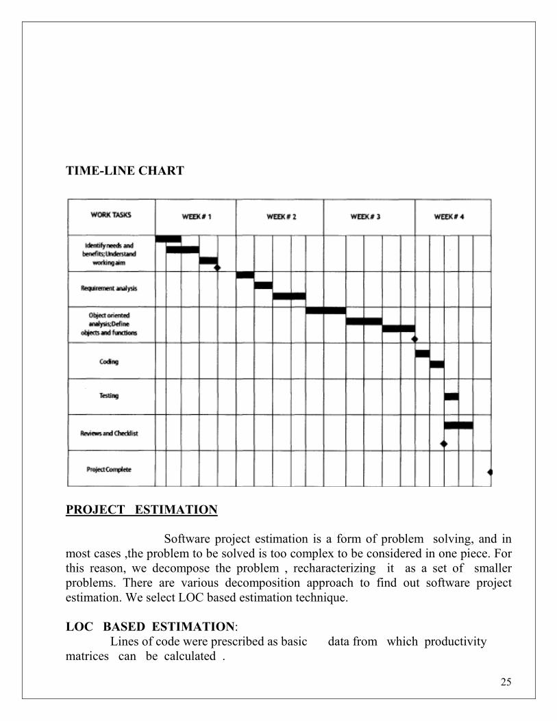
TIME-LINE CHART
PROJECT ESTIMATION
Software project estimation is a form of problem solving, and in most cases ,the problem to be solved is too complex to be considered in one piece. For this reason, we decompose the problem , recharacterizing it as a set of smaller problems. There are various decomposition approach to find out software project estimation. We select LOC based estimation technique. LOC BASED ESTIMATION: Lines of code were prescribed as basic data from which productivity matrices can be calculated .

26
LOC BASED ESTIMATION TABLE:
a=OPTIMISTIC LOC
b=PESSIMISTIC LOC m=MOST LIKELY E=EXPECTED E=a+4m+b 6 COST= EXPECTED LOC * $/LOC DAYS= EXPECTED LOC / LINE/DAY
FUNCTION OPTIM- ISTIC
MOST LIKELY
PESSI- MISTIC
EXPE- CTED
$/LINE LINE/ DAY
COST DAYS
MAIN 35 40 45 40 8 20 320 2
Mod 1 55 60 65 60 10 25 600 2.4
Mod 2 35 40 45 40 8 15 320 2.67
Mod 3 32 40 45 40 10 10 400 4
Mod 4 25 30 32 30 6 18 180 1.67
Mod 5 50 55 60 55 10 15 550 3.67
Mod 6 55 60 65 60 10 20 600 3
Mod 7 30 40 45 40 8 12 320 3.34
Mod 8 35 40 45 40 8 10 320 4
Mod 9 70 75 80 75 12 15 900 5
27
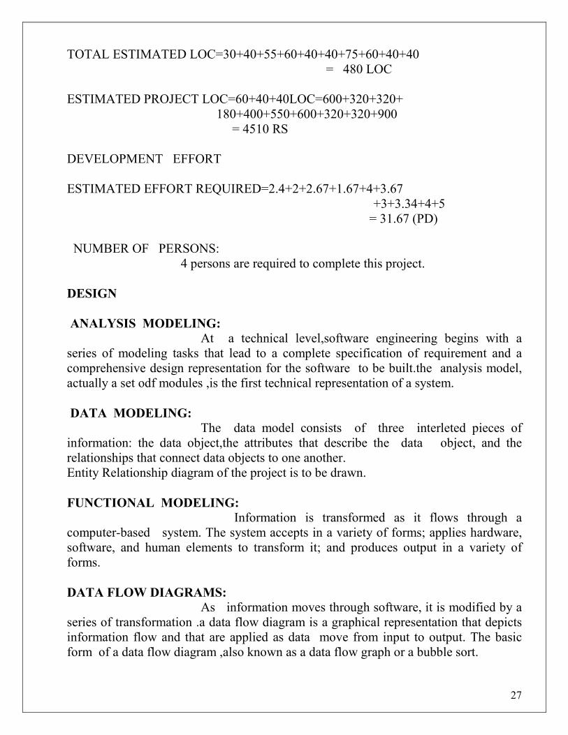
TOTAL ESTIMATED LOC=30+40+55+60+40+40+75+60+40+40 = 480 LOC ESTIMATED PROJECT LOC=60+40+40LOC=600+320+320+ 180+400+550+600+320+320+900 = 4510 RS DEVELOPMENT EFFORT ESTIMATED EFFORT REQUIRED=2.4+2+2.67+1.67+4+3.67 +3+3.34+4+5 = 31.67 (PD) NUMBER OF PERSONS: 4 persons are required to complete this project. DESIGN
ANALYSIS MODELING:
At a technical level,software engineering begins with a series of modeling tasks that lead to a complete specification of requirement and a comprehensive design representation for the software to be built.the analysis model, actually a set odf modules ,is the first technical representation of a system.
DATA MODELING:
The data model consists of three interleted pieces of information: the data object,the attributes that describe the data object, and the relationships that connect data objects to one another. Entity Relationship diagram of the project is to be drawn. FUNCTIONAL MODELING:
Information is transformed as it flows through a computer-based system. The system accepts in a variety of forms; applies hardware, software, and human elements to transform it; and produces output in a variety of forms.
DATA FLOW DIAGRAMS:
As information moves through software, it is modified by a series of transformation .a data flow diagram is a graphical representation that depicts information flow and that are applied as data move from input to output. The basic form of a data flow diagram ,also known as a data flow graph or a bubble sort.
28
Use- Case Analysis
Draw the following diagram related to Design if they are applicable. 1) Database structures, external file structures, internal data structures 2) Structure charts to depict module hierarchy. 3) GUI and Prototypes representing external (user) and internal (program module interface) interfaces. I4) Flowchart or procedural detail using PDL (program Design Language) at function or procedure level. Write down Design Specification
OR Do the following activities for Object-oriented Design 1) Layered or Subsystems architecture of system. 2) Identify Objects and describe its
• Protocols
• Implementation. 3) Sequence model to show the sequence of object interactions(Sequence or collaboration diagram) 4) State machine models to show how individual objects change their state in response to events ( state chart diagrams) 5) Object internee specifications Use – Case 1
Name : Issue of item Actors : Head of Department
Store Incharge
Goal : To issue the items to different departments and maintain a proper Record of that.
Preconditions :
1) The materials are inspected and are checked whether they stand up to the required standard. 2) The valid item code has to be entered. 3) The ordered quantity of item should not exceed the indented quantity of item. Steps
Actor’s actions System Response 1) Enter item code of item to be issued. 2) Display whether the item is valid item code.

29
3) Enter quantity to be issued along with 4) Check whether the issued quantity unit of measurement. Exceeds the indented quantity. 5) Checks the items & record any discrepancies. 6) Confirm that the items is to be issued
7) Ordered quantity is issued to indented department. Department by updating current closing balance.
Post Conditions :- The inventory database is updated reflecting the current availability.Status of items in the stores Use – Case 2 Name : Adjustments of items Actors : Head of Department
Store Incharge Goal : To recieve the items from the departments and maintain a proper Record of that . Preconditions : Item code has to be valid. Post Conditions :-
The inventory database is updated reflecting the current availability Status of items in the stores. Testing.
Design test cases for structural testing or white box testing.. White box testing (a.k.a. clear box testing, glass box testing, transparent box testing, translucent box testing or structural testing) uses an internal perspective of the system to design test cases based on internal structure. It requires programming skills to

30
identify all paths through the software. The tester chooses test case inputs to exercise paths through the code and determines the appropriate outputs Prepare test data Compare the results to test cases after running the data OR Design test cases to Perform functional or Black box testing. Black box testing takes an external perspective of the test object to derive test cases. These tests can be functional or non-functional, though usually functional. The test designer selects valid and invalid inputs and determines the correct output. There is no knowledge of the test object's internal structure. Prepare test data Compare the results to test cases after running the data. Values can be filled and compared in the following table:
Module name
Input data Expected result
Actual result Remark
Reviews
A software review is "A process or meeting during which a software product is [examined by] project personnel, managers, users, customers, user representatives, or other interested parties for comment or approval".
Software reviews may be divided into three categories:

31
• Software peer reviews are conducted by the author of the work product, or by one or more colleagues of the author, to evaluate the technical content and/or quality of the work.
• Software management reviews are conducted by management representatives to evaluate the status of work done and to make decisions regarding downstream activities.
• Software audit reviews are conducted by personnel external to the software project, to evaluate compliance with specifications, standards, contractual agreements, or other criteria.
Different types of reviews
• Code review is systematic examination (often as peer review) of computer source code.
• Pair programming is a type of code review where two persons develop code together at the same workstation.
• Inspection is a very formal type of peer review where the reviewers are following a well-defined process to find defects.
• Walkthrough is a form of peer review where the author leads members of the development team and other interested parties through a software product and the participants ask questions and make comments about defects.
• Technical review is a form of peer review in which a team of qualified personnel examines the suitability of the software product for its intended use and identifies discrepancies from specifications and standards
• Buddy checks is simply giving a document to someone else and asking them to look it closely will turn up defects we might never find on our own.
Any one review has to be conducted in the project.
9. Quiz on the subject:
Quiz should be conducted on tips in the laboratory, recent trends and subject knowledge of the subject. The quiz questions should be formulated such that questions are normally are from the scope outside of the books. However twisted questions and self formulated questions by the faculty can be asked but correctness of it is necessarily to be thoroughly checked before the conduction of the quiz.
32
10. Conduction of Viva-Voce Examinations:
Teacher should oral exams of the students with full preparation. Normally, the objective questions with guess are to be avoided. To make it meaningful, the questions should be such that depth of the students in the subject is tested Oral examinations are to be conducted in co-cordial environment amongst the teachers taking the examination. Teachers taking such examinations should not have ill thoughts about each other and courtesies should be offered to each other in case of difference of opinion, which should be critically suppressed in front of the students. Sample viva-voce questions:
What is Requirement Engineering ?
What are Functinoal and Non Functional Requirements in Software Enginering?
What is SRS? What is SDLC? Phases in software project development? What do you mean by Size-oriented metrics? How to do cost estimation for a project? Explain design phase in software project development? What are DFD and UML diagrams? What is testing? When to stop testing? What is black box testing? What is risk analysis? What id white box testing? What is unit testing? Explain integration testing? What is quality assurance? What is quality control?
What are the Different types of Architectures in Software Engineering?
What are use cases and class diagrams in Software Engineering?
What are sequence diagram? What are package diagram? What are collaboration
diagram?
What are the characteristics of good design? Name some Design Tools?
What is SDLC? What are the various SDLC models? Explain them
What are the Different types of Testing in software engineering ?
How to design a Test Case ?
11. Submission:
Document Standard: A] Page Size A4 Size B] Running text Justified text
33
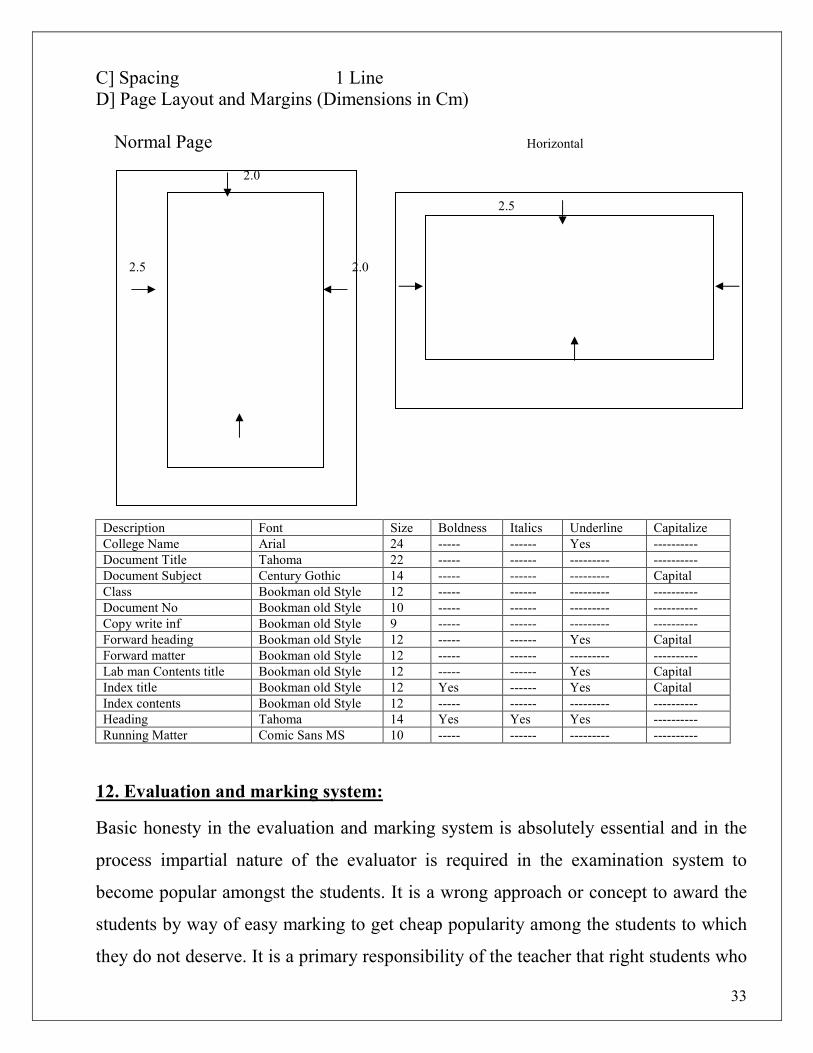
C] Spacing 1 Line D] Page Layout and Margins (Dimensions in Cm) Normal Page Horizontal
2.0 2.5 2.0 2.5 2.0 2.0 0.7” 0.7” 2.0 2.0
Description Font Size Boldness Italics Underline Capitalize
College Name Arial 24 ----- ------ Yes ----------
Document Title Tahoma 22 ----- ------ --------- ----------
Document Subject Century Gothic 14 ----- ------ --------- Capital
Class Bookman old Style 12 ----- ------ --------- ----------
Document No Bookman old Style 10 ----- ------ --------- ----------
Copy write inf Bookman old Style 9 ----- ------ --------- ----------
Forward heading Bookman old Style 12 ----- ------ Yes Capital
Forward matter Bookman old Style 12 ----- ------ --------- ----------
Lab man Contents title Bookman old Style 12 ----- ------ Yes Capital
Index title Bookman old Style 12 Yes ------ Yes Capital
Index contents Bookman old Style 12 ----- ------ --------- ----------
Heading Tahoma 14 Yes Yes Yes ----------
Running Matter Comic Sans MS 10 ----- ------ --------- ----------
12. Evaluation and marking system:
Basic honesty in the evaluation and marking system is absolutely essential and in the
process impartial nature of the evaluator is required in the examination system to
become popular amongst the students. It is a wrong approach or concept to award the
students by way of easy marking to get cheap popularity among the students to which
they do not deserve. It is a primary responsibility of the teacher that right students who
34
are really putting up lot of hard work with right kind of intelligence are correctly
awarded.
The marking patterns should be justifiable to the students without any ambiguity and
teacher should see that students are faced with unjust circumstances.