Embed Size (px)
Citation preview
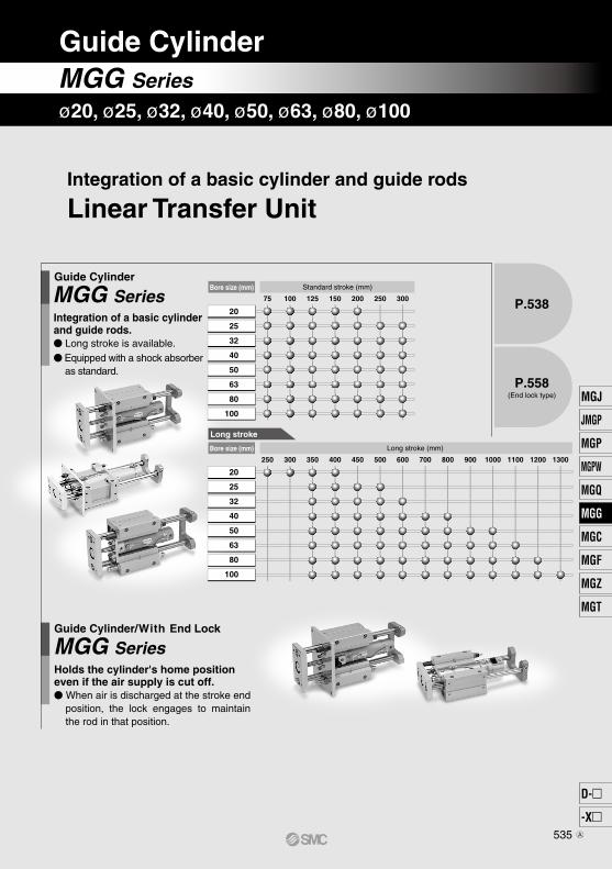
Integration of a basic cylinder and guide rods
Linear Transfer Unit
Bore size (mm)
20
25
32
40
50
63
80
100
250 300 350 400 500 600 700 800 900 1000 1100 1200 1300
Long stroke (mm)
Bore size (mm)
20
25
32
40
50
63
80
100
75 100 125 150 250 300
Standard stroke (mm)
P.538200
450
P.558(End lock type)
Guide Cylinder
MGG Series
Guide Cylinder/With End Lock
MGG Series
Long stroke
Integration of a basic cylinder and guide rods. Long stroke is available. Equipped with a shock absorber
as standard.
Holds the cylinder's home position even if the air supply is cut off. When air is discharged at the stroke end
position, the lock engages to maintain the rod in that position.
MGG Series
Guide Cylinder
ø20, ø25, ø32, ø40, ø50, ø63, ø80, ø100
535
MGJ
JMGP
MGP
MGPW
MGQ
MGG
MGC
MGF
MGZ
MGT
D-
-X
MGG
A
Lifter
Pusher
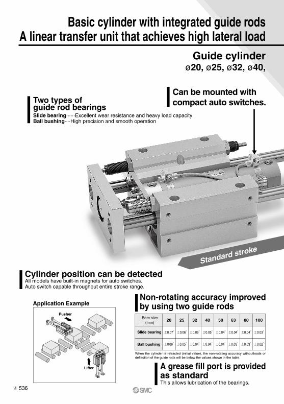
When the cylinder is retracted (initial value), the non-rotating accuracy withoutloads or deflection of the guide rods will be below the values shown in the table.
Guide cylinderø20, ø25, ø32, ø40,
Can be mounted with compact auto switches.
Basic cylinder with integrated guide rodsA linear transfer unit that achieves high lateral load
Cylinder position can be detectedAll models have built-in magnets for auto switches.Auto switch capable throughout entire stroke range.
Non-rotating accuracy improvedby using two guide rods
A grease fill port is providedas standardThis allows lubrication of the bearings.
Bore size(mm)
Slide bearing
Ball bushing
Two types ofguide rod bearingsSlide bearing······Excellent wear resistance and heavy load capacityBall bushing····High precision and smooth operation
Standard stroke
Application Example
536A
Guide body
Rear plate
Hexagon sockethead cap screw
Close
Movement
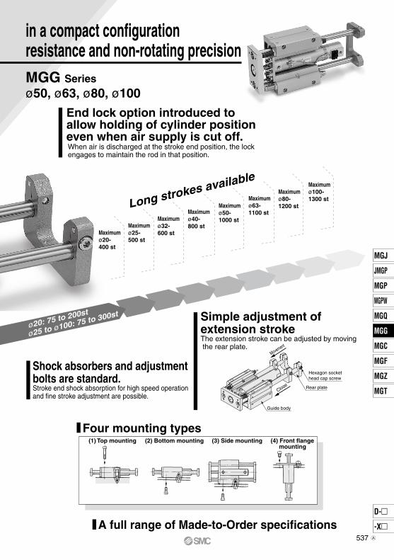
MGG Seriesø50, ø63, ø80, ø100
in a compact configurationresistance and non-rotating precision
End lock option introduced toallow holding of cylinder positioneven when air supply is cut off.When air is discharged at the stroke end position, the lock engages to maintain the rod in that position.
(4) Front flange mounting
(1) Top mounting (2) Bottom mounting (3) Side mounting
Simple adjustment ofextension strokeThe extension stroke can be adjusted by moving the rear plate.
Shock absorbers and adjustmentbolts are standard.Stroke end shock absorption for high speed operationand fine stroke adjustment are possible.
Four mounting types
A full range of Made-to-Order specifications
Long strokes available
Maximumø40-800 st
Maximumø20-400 st
Maximumø32-600 st
Maximumø25-500 st
Maximumø50-1000 st
Maximumø63-1100 st
Maximumø80-1200 st
Maximumø100-1300 st
ø20: 75 to 200st
ø25 to ø100: 75 to 300st
537
MGJ
JMGP
MGP
MGPW
MGQ
MGG
MGC
MGF
MGZ
MGT
D-
-X
MGG
A
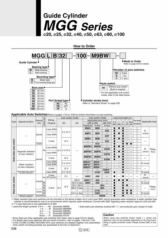
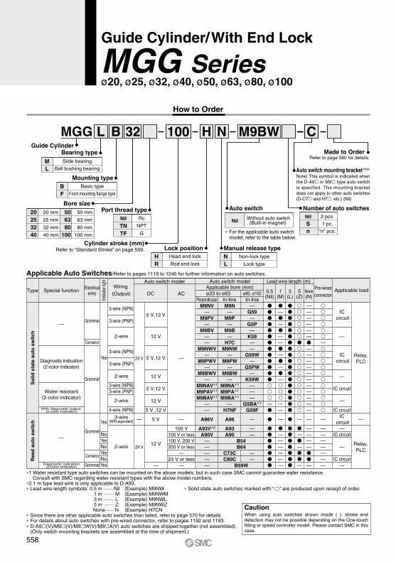
L M9BWB 32Guide Cylinder
MGG 100
Number of auto switchesNilSn
2 pcs.1 pc.
“n” pcs.
Auto switch
∗ For the applicable auto switch model, refer to the table below.
Nil Without auto switch(Built-in magnet)
Cylinder stroke (mm)Refer to “Standard Stroke” on page 539.
Port thread typeRc
NPTG
NilTNTF
Bore size20253240506380
100
20 mm25 mm32 mm40 mm50 mm63 mm80 mm
100 mm
Mounting typeBF
Basic typeFront mounting flange type
Bearing typeML
Slide bearingBall bushing
Made to Order Refer to page 540 for details.
Applicable Auto Switches/Refer to pages 1119 to 1245 for further information on auto switches.
How to Order
Guide Cylinder
MGG Seriesø20, ø25, ø32, ø40, ø50, ø63, ø80, ø100
∗ Lead wire length symbols: 0.5 m ·······Nil (Example) M9NW 1 m ······· M (Example) M9NWM 3 m ······· L (Example) M9NWL 5 m ······· Z (Example) M9NWZ None······· N (Example) H7CN
∗ Solid state auto switches marked with “ ” are produced upon receipt of order.
∗ Since there are other applicable auto switches than listed, refer to page 570 for details.∗ For details about auto switches with pre-wired connector, refer to pages 1192 and 1193.∗ D-A9(V)/M9(V)/M9W(V)/M9A(V) auto switches are shipped together (not assembled).
(Only switch mounting brackets are assembled at the time of shipment.)
When using auto switches shown inside ( ), stroke end detection may not be possible depending on the One-touch fitting or speed controller model. Please contact SMC in this case.
Caution
∗1 Water resistant type auto switches can be mounted on the above models, but in such case SMC cannot guarantee water resistance. A water resistant typecylinder is recommended for use in an environment which requires water resistance. Consult with SMC regarding water resistant types for ø20 and ø25.
∗2 1 m type lead wire is only applicable to D-A93.
Yes
Yes
Yes
Yes
Yes
Type Special function Electricalentry
—
100 V100 V or less100 V, 200 V200 V or less
—24 V or less
—
Wiring (Output)
Auto switch model
DC
24 V
24 V
5 V,12 V
12 V
5 V,12 V
12 V
5 V,12 V
12 V
5 V ,12 V
5 V
12 V
—
AC
Lead wire length (m)
0.5(Nil)
—
3(L)
1(M)
—————————
—
——————
5(Z)
—
———
None(N)
—————————————————
—
—————
—
—
———————
Applicable loadPre-wiredconnector
IC circuit
—
IC circuit
—
IC circuit
—
IC circuitIC
circuit—
IC circuit
—
IC circuit—
Relay,PLC
Relay,PLC
Auto switch modelApplicable bore (mm)ø20 to ø63 ø80, ø100
In-linePerpendicularM9N—
M9P—
M9B—
H7CM9NW
—M9PW
—M9BW
—M9NA∗1
M9PA∗1
M9BA∗1
—H7NF
A96
A93A90
C73CC80C
—G59—
G5P—
K59——
G59W—
G5PW—
K59W———
G5BA∗1
G59F
—
——
——
M9NV—
M9PV—
M9BV——
M9NWV—
M9PWV—
M9BWV—
M9NAV∗1
M9PAV∗1
M9BAV∗1
——
A96V
A93V∗2
A90V—————
B54B64
B59W
—
—
—
—
—
In-lineIndic
ator
light
Ree
d a
uto
sw
itch
So
lid s
tate
au
to s
wit
ch
Diagnostic indication(2-color indicator)
With diagnostic output (2-color indicator)
Diagnostic indication(2-color indicator)
Water resistant(2-color indicator)
Connector
Connector
Grommet
Grommet
Grommet
Grommet
No
No
No
3-wire (NPN)
3-wire (PNP)
3-wire (NPN)
3-wire (NPN)
4-wire (NPN)
3-wire (PNP)
3-wire (PNP)
2-wire
2-wire
2-wire
2-wire
3-wire(NPN equivalent)
538
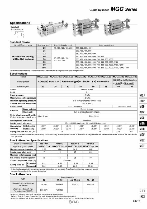
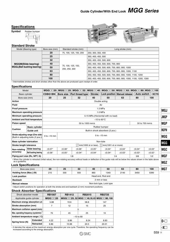
Specifications
MGG SeriesGuide Cylinder
SymbolRubber bumper
250, 300, 350, 400
350, 400, 450, 500
350, 400, 450, 500, 600
350, 400, 450, 500, 600, 700, 800
350, 400, 450, 500, 600, 700, 800, 900, 1000
350, 400, 450, 500, 600, 700, 800, 900, 1000, 1100
350, 400, 450, 500, 600, 700, 800, 900, 1000, 1100, 1200
350, 400, 450, 500, 600, 700, 800, 900, 1000, 1100, 1200, 1300
Standard StrokeModel (Bearing type) Bore size (mm)
MGGM (Slide bearing)MGGL (Ball bushing)
20 25 32 40 50 63 80100
Standard stroke (mm)
75, 100, 125, 150, 200
75, 100, 125, 150,200, 250, 300
Long stroke (mm)
∗ Intermediate strokes and short strokes other than the above are produced upon receipt of order.
∗ When the cylinder is retracted (initial value), the non-rotating accuracy without loads or deflection of the guide rods will be below the values shown in the table above as a guideline.
Specifications
Action
Fluid
Proof pressure
Maximum operating pressure
Minimum operating pressure
Ambient and fluid temperature
Piston speed
Cushion
Base cylinder lubrication
Stroke length tolerance
Piping port size (Rc, NPT, G)
20
MGG20
25
MGG25
1/8
32
MGG32
0 to –10 mm
±0.07°±0.06°
1/4 3/8 1/2
0 to –15 mm
40
MGG40
63
MGG63
50
MGG50
80
MGG80
100
MGG100
Double acting
Air
1.5 MPa
1.0 MPa
0.15 MPa (Horizontal with no load)
–10 to 60°C
Rubber bumper
Built-in shock absorbers (2 pcs.)
Non-lube
mm (1000 st or less), mm (1001 st or more)
Basic cylinder
Guide unit
Slide bearing
Ball bushing
+1.9+0.2
+2.3+0.2
50 to 700 mm/s50 to 1000 mm/s
±0.06°±0.05°
±0.06°±0.04°
±0.05°±0.04°
±0.04°±0.04°
±0.04°±0.03°
±0.04°±0.03°
±0.03°±0.02°
CDG1ZN ZBore size Port thread type Stroke Auto switch
Shock Absorber Specifications
Maximum energy absorption (J)
Stroke absorption (mm)
Maximum collision speed (m/s)
Max. operating frequency (cycle/min)∗
Ambient temperature range (°C)
Spring force (N)
Shock absorber model
Applicable guide cylinder
RB1007MGG20
5.88
7
70
4.22
6.860
RB1412MGG25, 32
19.6
12
45
6.86
15.98
RB2015MGG40, 50, 63
58.8
15
25
8.34
20.5
RB2725MGG80, 100
147
25
10
8.83
20.01
Extended
Retracted
5
–10 to 80
∗ It denotes the values at the maximum energy absorption per one cycle. Therefore, the operating frequency can be increased according to the energy absorption.
Stroke adjusting range (One side)[Built-in adjusting bolts (2 pcs.)]
Non-rotating∗accuracy
Shock Absorbers
20Standard (shock absorber
RB series)
Shock absorber soft typeRJ series type (-XB22)
TypeBore size (mm)
RB1007
RJ1007H
RB1412
RJ1412H
25, 32 40, 50, 63
RB2015
—
RB2725
—
80, 100
∗ The shock absorber service life is different from that of the MGG cylinder.Refer to “Specific Product Precautions” for each shock absorber for the replacement period.
∗ The shock absorber soft type RJ series type (-XB22) is a made to order specification. For details, refer to page 1296.
Model
Basic cylinder
Bore size (mm)
CDG1BN Bore size Port thread type
Stroke Auto switchZ
539
MGJ
JMGP
MGP
MGPW
MGQ
MGG
MGC
MGF
MGZ
MGT
D-
-X
MGG
A
OUT IN
20 25 32 40 50
(kg)
1008063
LB Type (Ball bushing bearing, Basic type)
LF Type (Ball bushing bearing, Front mounting flange type)
MB Type (Slide bearing, Basic type)
MF Type (Slide bearing, Front mounting flange type)
(kg)
20 25 32 40
0.69
0.109
1.14
0.135
1.61
0.203
3.09
0.326
5.23
0.509
8.29
0.679
13.09
0.948
18.58
1.265
50 63 80 100
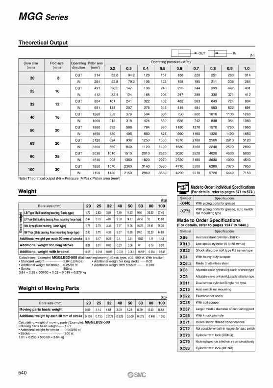
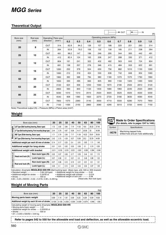
Weight
Weight of Moving Parts
1.72
2.44
1.71
2.42
0.14
0.01
0.011
2.82
3.79
2.79
3.75
0.17
0.01
0.018
3.84
4.87
3.36
4.39
0.25
0.02
0.019
7.19
9.38
7.17
9.37
0.4
0.03
0.031
11.63
14.17
11.36
13.89
0.61
0.06
0.061
37.46
45.98
36.36
44.89
1.48
0.26
0.548
26.32
33
25.61
32.29
1.11
0.19
0.384
16.6
20.58
16.22
20.2
0.82
0.1
0.269
20
25
32
40
50
63
80
100
8
10
12
16
20
20
25
30
OUT
IN
OUT
IN
OUT
IN
OUT
IN
OUT
IN
OUT
IN
OUT
IN
OUT
IN
314
264
491
412
804
691
1260
1060
1960
1650
3120
2800
5030
4540
7850
7150
0.2
62.8
52.8
98.2
82.4
161
138
252
212
392
330
624
560
1010
908
1570
1430
0.3
94.2
79.2
147
124
241
207
378
318
588
495
936
840
1510
1360
2360
2150
0.4
126
106
196
165
322
276
504
424
784
660
1250
1120
2010
1820
3140
2860
0.5
157
132
246
206
402
346
630
530
980
825
1560
1400
2520
2270
3930
3580
0.6
188
158
295
247
482
415
756
636
1180
990
1870
1680
3020
2720
4710
4290
0.7
220
185
344
288
563
484
882
742
1370
1160
2180
1960
3520
3180
5500
5010
0.8
251
211
393
330
643
553
1010
848
1570
1320
2500
2240
4020
3630
6280
5720
0.9
283
238
442
371
724
622
1130
954
1760
1490
2810
2520
4530
4090
7070
6440
1.0
314
264
491
412
804
691
1260
1060
1960
1650
3120
2800
5030
4540
7850
7150
Symbol Specifications
XB6
XB13
XB22
XC4
XC6XC8
XC9
XC11
XC13
XC22
XC35
XC37
XC56
XC71
XC72
XC73
XC79
XC83
Heat resistant cylinder (150°C)
Low speed cylinder (5 to 50 mm/s)
Shock absorber soft type RJ series type
With heavy duty scraper
Made of stainless steel
Adjustable stroke cylinder/Adjustable extension type
Adjustable stroke cylinder/Adjustable retraction type
Dual stroke cylinder/Single rod type
Auto switch rail mounting
Fluororubber seals
With coil scraper
Larger throttle diameter of connecting port
With knock pin hole
Helical insert thread specifications
Not possible for built-in magnet for auto switch
Cylinder with lock (CDNG)
Machining tapped hole, drilled hole, and pin hole additionally
Cylinder with lock (MDNB)
Theoretical Output
Bore size(mm)
Rod size(mm)
Operatingdirection
Piston area(mm2)
Operating pressure (MPa)
(N)
Note) Theoretical output (N) = Pressure (MPa) x Piston area (mm2)
Bas
ic w
eig
ht
Bore size (mm)
Additional weight per each 50 mm of stroke
Additional weight for long stroke
Additional weight with bracket
Calculation: (Example) MGGLB32-500 (Ball bushing bearing) (Basic type, ø32, 500 st, With bracket)• Standard weight ····················· 3.84 (LB type) • Additional weight for long stroke ······0.02• Additional weight for stroke ···· 0.25/50 st • Additional weight with bracket ··········0.019• Stroke ····································· 500 st3.84 + 0.25 x 500/50 + 0.02 + 0.019 = 6.379 kg
Bore size (mm)
Moving parts basic weight
Additional weight by each 50 mm of stroke
Calculating weight of moving parts (Example): MGGLB32-500• Moving parts basic weight ······· 1.61• Additional weight for stroke ····· 0.203/50 st• Stroke ······································ 500 st1.61 + 0.203 x 500/50 = 3.64 kg
MGG Series
Made to Order Specifications(For details, refer to pages 1247 to 1440.)
-X440
-X772
With piping ports for grease
With piping ports for grease, auto switchrail mounting type
Symbol Specifications
Made to Order: Individual Specifications(For details, refer to pages 571 to 574.)
540
Series Applicable to Operating Environments that Do Not Accept Copper• Copper (Cu) and zinc (Zn)-free ········· 25A series• Copper and Fluorine-free ·················· 20 series∗ For details, refer to the SMC website.
20, 25, 32, 40, 50, 63
ø32 to ø50
ø63 to ø100
Bore size (mm)
RY
2014
79
2514
79
3214
81
4015
89
50 16
104
63 16
119
(mm)
ø63
Bore size (mm)
-XC6MGGM R
RV
M9NA
Bore size (mm) 32, 40, 50, 63, 80, 100Double acting
Slide beaning
Rubber bumper Built-in shock absorbers
Band mounting
Piston rod and rod end nut made of stainless steel
Stainless steel used for all iron parts
Stainless steel rod end moving parts
Stainless steel rods
–XC6–XC6A–XC6B–XC6C
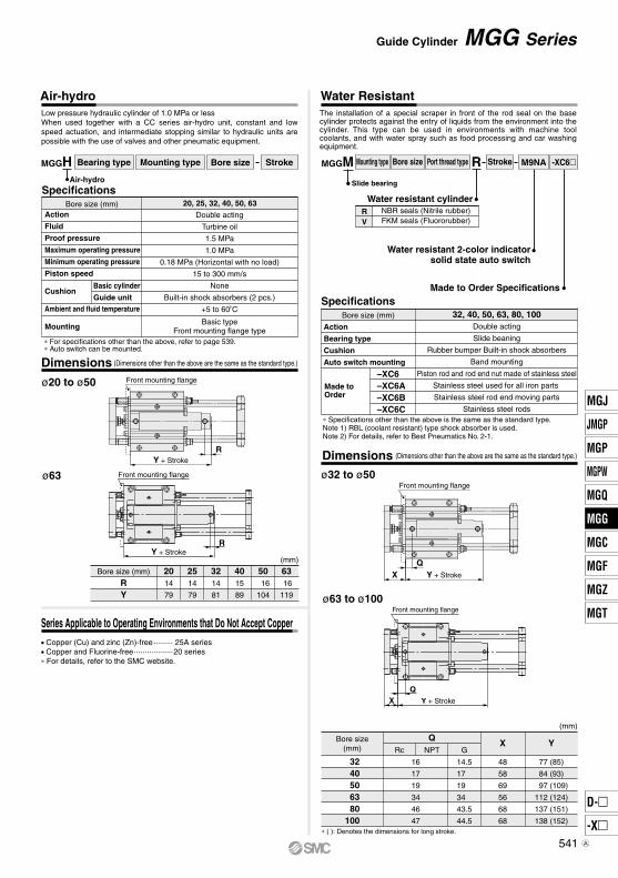
Air-hydro Water ResistantLow pressure hydraulic cylinder of 1.0 MPa or lessWhen used together with a CC series air-hydro unit, constant and low speed actuation, and intermediate stopping similar to hydraulic units are possible with the use of valves and other pneumatic equipment.
The installation of a special scraper in front of the rod seal on the base cylinder protects against the entry of liquids from the environment into the cylinder. This type can be used in environments with machine tool coolants, and with water spray such as food processing and car washing equipment.
Specifications
Port thread typeMounting type Bore size Stroke
Action
Fluid
Proof pressure
Maximum operating pressure
Minimum operating pressure
Piston speed
Cushion
Ambient and fluid temperature
Mounting
Basic cylinder
Guide unit
∗ For specifications other than the above, refer to page 539. ∗ Auto switch can be mounted.
Double acting
Turbine oil
1.5 MPa
1.0 MPa
0.18 MPa (Horizontal with no load)
15 to 300 mm/s
None
Built-in shock absorbers (2 pcs.)
+5 to 60 C
Basic typeFront mounting flange type
Dimensions
ø20 to ø50
(Dimensions other than the above are the same as the standard type.)
(Dimensions other than the above are the same as the standard type.)
Slide bearing
Water resistant cylinderNBR seals (Nitrile rubber)FKM seals (Fluororubber)
Water resistant 2-color indicatorsolid state auto switch
Made to Order Specifications
Specifications
Dimensions
Action
Bearing type
Cushion
Auto switch mounting
Made to Order
∗ Specifications other than the above is the same as the standard type.Note 1) RBL (coolant resistant) type shock absorber is used.Note 2) For details, refer to Best Pneumatics No. 2-1.
MGG SeriesGuide Cylinder
Front mounting flange
QX Y + Stroke
MGGHAir-hydro
Bearing type Mounting type Bore size Stroke
16
17
19
34
46
47
14.5
17
19
34
43.5
44.5
48
58
69
56
68
68∗ ( ): Denotes the dimensions for long stroke.
32 40 50 63 80100
77 (85)
84 (93)
97 (109)
112 (124)
137 (151)
138 (152)
(mm)
Y + StrokeR
Front mounting flange
RY + Stroke
Front mounting flange
XQ
Y + Stroke
Front mounting flange
Bore size(mm)
X YQ
Rc NPT G
541
MGJ
JMGP
MGP
MGPW
MGQ
MGG
MGC
MGF
MGZ
MGT
D-
-X
MGG
A
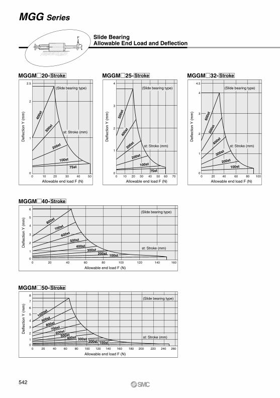
Slide BearingAllowable End Load and Deflection
MGG Series
MGGM 20- Stroke Stroke StrokeMGGM 25- MGGM 32-
MGGM 40-
MGGM 50-
Stroke
Stroke
F
Y
00
0
1
2
3
4
5
6
1
2
2.5
(Slide bearing type)
(Slide bearing type)
(Slide bearing type) (Slide bearing type)
400s
t
500s
t
500s
t
600s
t
400s
t
400s
t
300s
t
300st
300st200st
200st
200st100st
100st100st75st
75st
st: Stroke (mm)
st: Stroke (mm)
(Slide bearing type)
st: Stroke (mm)
st: Stroke (mm) st: Stroke (mm)
10
0 20 40 60 80 100 120 140 160
20 30 40 50 00
1
2
3
4
10 20 30 40 50 60 70 00
1
2
3
4
4.5
20 40 60 80 100
Allowable end load F (N)
Allowable end load F (N)
Def
lect
ion
Y (
mm
)D
efle
ctio
n Y
(m
m)
0
1
2
3
4
5
7
6
8
0 20 40 60 80 100 120 140 160 180 200 220 240 260
Allowable end load F (N)
Def
lect
ion
Y (
mm
)
Def
lect
ion
Y (
mm
)
Def
lect
ion
Y (
mm
)
Allowable end load F (N) Allowable end load F (N)
100st
100st200st300st400st500st600st
800st
700st
900st1000st
200st300st
400st500st
600st700st
800st
542
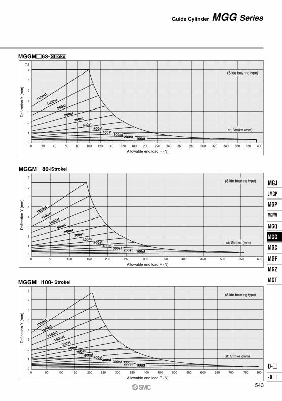
80-MGGM
MGGM 100-
Stroke
Stroke
Stroke
MGG SeriesGuide Cylinder
MGGM 63-
0
1
2
3
4
5
6
7
7.5
(Slide bearing type)
st: Stroke (mm)
0 20 40 60 80 100 120 140 160 180 200 220 240 260 280 300 320 340 360 380 400
Allowable end load F (N)
Def
lect
ion
Y (
mm
)
100st200st300st400st
500st600st
700st800st
900st1000st1100st
0
1
2
3
4
5
6
7
8(Slide bearing type)
st: Stroke (mm)
0 50 100 150 200 250 300 350 400 450 500 550 600
Allowable end load F (N)
Def
lect
ion
Y (
mm
)
100st200st300st400st500st
600st700st800st
900st1000st1100st1200st
0
1
2
3
4
5
6
7
8(Slide bearing type)
st: Stroke (mm)
0 50 100 150 200 250 300 350 400 450 500 550 600 650 700 750 800
Allowable end load F (N)
Def
lect
ion
Y (
mm
)
100st200st300st400st500st600st700st800st900st
1000st1100st1200st1300st
543
MGJ
JMGP
MGP
MGPW
MGQ
MGG
MGC
MGF
MGZ
MGT
D-
-X
MGG
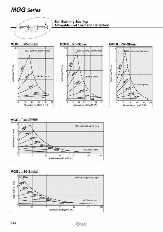
Ball Bushing BearingAllowable End Load and Deflection
MGG Series
F
YMGGL 20- MGGL 25- MGGL 32-
MGGL 40-
MGGL 50-
Stroke Stroke Stroke
Stroke
Stroke
00
1
2
2.5
(Ball bushing bearing type)
400s
t30
0st
200st
100st
75st
st: Stroke (mm)
10 20 30 40 50
Allowable end load F (N)
Def
lect
ion
Y (
mm
)
(Ball bushing bearing type)
500s
t40
0st
300st
200st
100st
75st
st: Stroke (mm)
00
1
2
3
3.5
10 20 30 40 50 60
Def
lect
ion
Y (
mm
)
Allowable end load F (N)
(Ball bushing bearing type)
500s
t
600s
t
400s
t
300st
200st
100st
st: Stroke (mm)
00
1
2
3
4
20 40 60 80 100
Def
lect
ion
Y (
mm
)
Allowable end load F (N)
0
1
2
3
4(Ball bushing bearing type)
st: Stroke (mm)
0 20 40 60 80 100 120
Allowable end load F (N)
Def
lect
ion
Y (
mm
)
100st200st
300st400st
500st600st
700st
800st
(Ball bushing bearing type)
st: Stroke (mm)
0
1
2
3
0 20 40 60 80 100 120
Allowable end load F (N)
Def
lect
ion
Y (
mm
)
100st
900st
200st300st
400st500st
600st
800st
700st
544
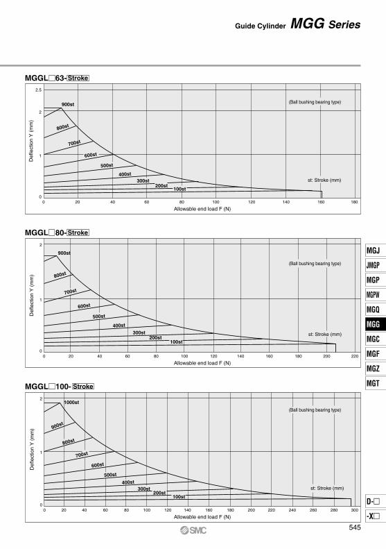
MGGL 63-
MGGL 80-
MGGL 100-
Stroke
Stroke
Stroke
MGG SeriesGuide Cylinder
0
1
2
2.5
(Ball bushing bearing type)
(Ball bushing bearing type)
(Ball bushing bearing type)
st: Stroke (mm)
0 20 40 60 80 100 120 140 160 180
Allowable end load F (N)
Def
lect
ion
Y (
mm
)
100st
900st
200st300st
400st
500st
600st
700st
800st
0
1
2
st: Stroke (mm)
0 20 40 60 80 100 120 140 160 180 200 220
Allowable end load F (N)
Def
lect
ion
Y (
mm
)
100st
900st
200st300st
400st
500st
600st
700st
800st
0
1
2
st: Stroke (mm)
0 20 40 60 80 100 120 140 160 180 200 220 240 260 280 300
Allowable end load F (N)
Def
lect
ion
Y (
mm
)
100st
1000st
200st300st
400st500st
600st
700st
800st
900st
545
MGJ
JMGP
MGP
MGPW
MGQ
MGG
MGC
MGF
MGZ
MGT
D-
-X
MGG

Slide BearingAllowable End Load and Deflection
MGGM 20- MGGM 25- MGGM 32-
MGGM 40-
MGGM 50-
Stroke Stroke Stroke
Stroke
Stroke
MGG Series
F
Y
00
0.5
1
1.2
400s
t30
0st
200st
100st
75st
st: Stroke (mm)
10 20 30 40 50
Allowable end load F (N)
Def
lect
ion
Y (
mm
)
(Slide bearing type) (Slide bearing type)
(Slide bearing type)
(Slide bearing type)
(Slide bearing type)
500s
t40
0st
300st
200st
100st
75st
st: Stroke (mm)
00
0.5
1
1.5
2
10 20 30 40 50 60 70
Def
lect
ion
Y (
mm
)
Allowable end load F (N)
500s
t
600s
t
400s
t
300st
200st
100st
st: Stroke (mm)
00
0.5
1
1.5
2.2
2
20 40 60 80 100
Def
lect
ion
Y (
mm
)
Allowable end load F (N)
0
0.5
1
1.5
2.5
2
3
st: Stroke (mm)
0 20 40 60 80 100 120 140 160
Allowable end load F (N)
Def
lect
ion
Y (
mm
)
100st200st300st
400st500st
600st700st
800st
st: Stroke (mm)
0
1.5
1
0.5
2.5
2
4
3.5
3
0 20 40 60 80 100 120 140 160 180 200 220 240 260
Allowable end load F (N)
Def
lect
ion
Y (
mm
)
100st200st300st400st500st600st
800st900st1000st
700st
546

MGGM 63-
MGGM 80-
MGGM 100-
Stroke
Stroke
Stroke
MGG SeriesGuide Cylinder
0
1
1.5
0.5
2
2.5
3
3.5
3.7
(Slide bearing type)
(Slide bearing type)
(Slide bearing type)
st: Stroke (mm)
0 20 40 60 80 100 120 140 160 180 200 220 240 260 280 300 320 340 360 380 400
Allowable end load F (N)
Def
lect
ion
Y (
mm
)
100st200st300st400st
500st600st
700st800st
900st1000st
1100st
0
1
0.5
1.5
2
2.5
3
3.5
4
st: Stroke (mm)
0 50 100 150 200 250 300 350 400 450 500 550 600
Allowable end load F (N)
Def
lect
ion
Y (
mm
)
100st200st300st400st500st
600st700st
800st900st
1000st1100st
1200st
0
1.5
2
2.5
0.5
1
3
3.5
4
st: Stroke (mm)
0 10050 150 200 250 300 350 400 450 500 550 600 650 700 750 800
Allowable end load F (N)
Def
lect
ion
Y (
mm
)
100st200st300st400st500st600st
700st800st
900st1000st
1100st1200st1300st
547
MGJ
JMGP
MGP
MGPW
MGQ
MGG
MGC
MGF
MGZ
MGT
D-
-X
MGG
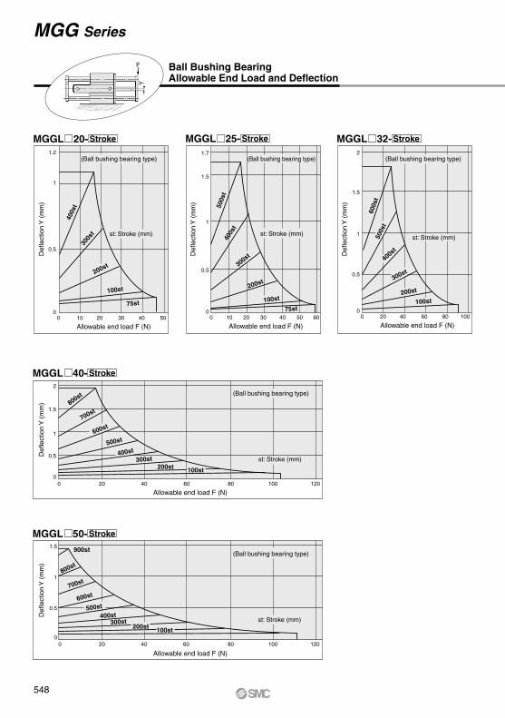
MGGL 20- MGGL 25- MGGL 32-
MGGL 40-
MGGL 50-
Ball Bushing BearingAllowable End Load and Deflection
Stroke Stroke Stroke
Stroke
Stroke
MGG Series
F
Y
00
0.5
1
1.2
400s
t30
0st
200st
100st
75st
st: Stroke (mm)
10 20 30 40 50
Allowable end load F (N)
Def
lect
ion
Y (
mm
)
(Ball bushing bearing type) (Ball bushing bearing type)
(Ball bushing bearing type)
(Ball bushing bearing type)
(Ball bushing bearing type)
500s
t40
0st
300st
200st
100st
75st
st: Stroke (mm)
00
0.5
1
1.5
1.7
10 20 30 40 50 60
Def
lect
ion
Y (
mm
)
Allowable end load F (N)
500s
t
600s
t
400s
t
300st
200st
100st
st: Stroke (mm)
00
0.5
1
1.5
2
20 40 60 80 100
Def
lect
ion
Y (
mm
)
Allowable end load F (N)
0
0.5
1
1.5
2
st: Stroke (mm)
0 20 40 60 80 100 120
Allowable end load F (N)
Def
lect
ion
Y (
mm
)
100st200st300st
400st500st
600st700st
800st
0
0.5
1
1.5
st: Stroke (mm)
0 20 40 60 80 100 120
Allowable end load F (N)
Def
lect
ion
Y (
mm
)
100st
900st
200st300st
400st500st
600st700st
800st
548

MGGL 63-
MGGL 80-
MGGL 100-
Stroke
Stroke
Stroke
MGG SeriesGuide Cylinder
0
1
1.2
0.5
(Ball bushing bearing type)
st: Stroke (mm)
0 20 40 60 80 100 120 140 160 180
Allowable end load F (N)
Def
lect
ion
Y (
mm
)
100st
900st
200st300st
400st
500st
600st
700st
800st
0
1
0.5
(Ball bushing bearing type)
st: Stroke (mm)
0 20 40 60 80 100 120 140 160 180 200 220
Allowable end load F (N)
Def
lect
ion
Y (
mm
)
100st
900st
200st300st
400st
500st
600st
700st
800st
0
1
0.5
(Ball bushing bearing type)
st: Stroke (mm)
0 20 40 60 80 100 120 140 160 180 200 220 240 260 280 300
Allowable end load F (N)
Def
lect
ion
Y (
mm
)
100st
1000st
200st300st
400st500st
600st
700st
800st
900st
549
MGJ
JMGP
MGP
MGPW
MGQ
MGG
MGC
MGF
MGZ
MGT
D-
-X
MGG

L L
Slide Bearing: MGGM - Stroke
Ball Bushing Bearing: MGGL - Stroke
(Set the maximum allowable load so that it does not exceed the following percentages of the theoretical output: 35% for ø20, 40% for ø25, 50% for ø32, 55% for ø40 and ø50, and 50% for ø63, ø80 and ø100.)
(Set the maximum allowable load so that it does not exceed the following percentages of the theoretical output: 40% for ø20, 50% for ø25, and 60% for ø32, ø40, ø50, ø63, ø80 and ø100.)
MGG Series
Allowable Eccentric Load
10
50
100
500
1000
2000
3000P = 0.5 MPa
0 50 100 150 200
MGGM100-MGGM80-MGGM63-
MGGM50-
MGGM40-
MGGM32-
MGGM25-
MGGM20-
Eccentric distance from center of cylinder to load center of gravity L (mm)
Eccentric distance from center of cylinder to load center of gravity L (mm)
10
50
500
100
1000
2000
3000P=0.5 MPa
0 50 100 150 200
MGGL100-MGGL80-MGGL63-MGGL50-
MGGL40-MGGL32-
MGGL25-
MGGL20-
Allo
wab
le e
ccen
tric
load
W (
N)
Allo
wab
le e
ccen
tric
load
W (
N)
550

Ball bushing
Slide bearing
Front mounting flange type
Long stroke
A
A'
View A-A'
r t qy w ioue!0 #6 #8 !3!7@2@3@4 #7
!8
@9
#4
!6!2 #8 !1#3
!5!9@1@0#1#2!4
@9 @6 @8 #0 @5 #5
@7
!7
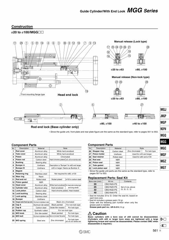
MGG SeriesGuide Cylinder
123
4
5678910111213
14
1516
17
18
1920212223242526272829303132
Rod coverTube coverPiston
Piston rod
BushingBumperBumperMagnetWear ringRod end nutHead coverCylinder tubeGuide bodySmall flangeLarge flangeFront plateRear plateSlide bearingBall bushing
Guide rod
End bracketFlat washerSpring washerFeltHolderType C retaining ring for holeBracketShock absorberAdjustment boltNutParallel pinNippleHexagon socket head cap screwHexagon socket head cap screw
Aluminum alloyAluminum alloyAluminum alloyStainless stealCarbon steelBearing alloy
UrethaneUrethane
—Resin
Carbon steelAluminum alloyAluminum alloyAluminum alloyCarbon steelCarbon steelCarbon steel
Cast ironBearing alloy
—Carbon steelCarbon steelCarbon steelCarbon steelCarbon steel
FeltStainless steal
Carbon tool steelStainless steal
—Carbon steelCarbon steelCarbon steel
—Carbon steelCarbon steel
Hard anodizedHard anodized
Nickel platingNickel plating
For long stroke
For basic typeFor front mounting flange type
Hard chrome plating For ø32 to ø100
Hard chrome platingQuenched, hard chrome plating
Zinc chromatedZinc chromated
For cylinder mountingFor large/small flange mounting
For slide bearingFor ball bushing
Hard anodizedHard anodized
For ø20,ø25
ø32 or larger is common.
Zinc chromated
Anodized
Nickel platingPainted
For slide bearingFor ball bushing
Nickel platingZinc chromatedZinc chromated
Phosphate coated
Nickel platingNickel plating
Quenched, nickel platingNickel plating
333435363738
Guide boltHexagon socket head cap screwHexagon socket head cap screwRod sealPiston sealTube gasket
Carbon steelCarbon steelCarbon steel
NBRNBRNBR
For front plate mountingFor rear plate mountingFor bracket mounting
Nickel platingZinc chromatedZinc chromated
DescriptionNo. Material Note DescriptionNo. Material Note
CG1N20Z-PSCG1N25Z-PSCG1N32Z-PSCG1N40Z-PS
20253240
1. Do not replace the bushings.2. To replace a seal, apply grease to the new seal before installing it.
If the cylinder is put into operation without applying grease to the seal, it could cause the seal to wear significantly, leading to premature air leakage.
3. Basic cylinders with a bore size of ø50 cannot be disassembled.When disassembling cylinders with bore sizes of ø20 through ø40, grip the double flat part of either the tube cover or the rod cover with a vise and loosen the other side with a wrench or a monkey wrench etc., and then remove the cover. When retightening, tighten approximately 2 degrees more than the original position. (Cylinders with ø50 or larger bore sizes are tightened with a large tightening torque and cannot be disassembled. If disassembly is required, please contact SMC.)
Caution
Replacement Parts: Seal KitBore size (mm) Kit no. Contents
Set of nos. above #6, #7, #8.
Note) Refer to the following precautions for disassembly/replacement. Order with the kit number according to the bore size.
∗ Seal kit includes a grease pack (10 g). Order with the following part number when only the grease pack is needed.Grease pack part no.: GR-S-010 (10 g)
ø20 to ø50/MGG
Construction
Component Parts Component Parts
551
MGJ
JMGP
MGP
MGPW
MGQ
MGG
MGC
MGF
MGZ
MGT
D-
-X
MGG
A
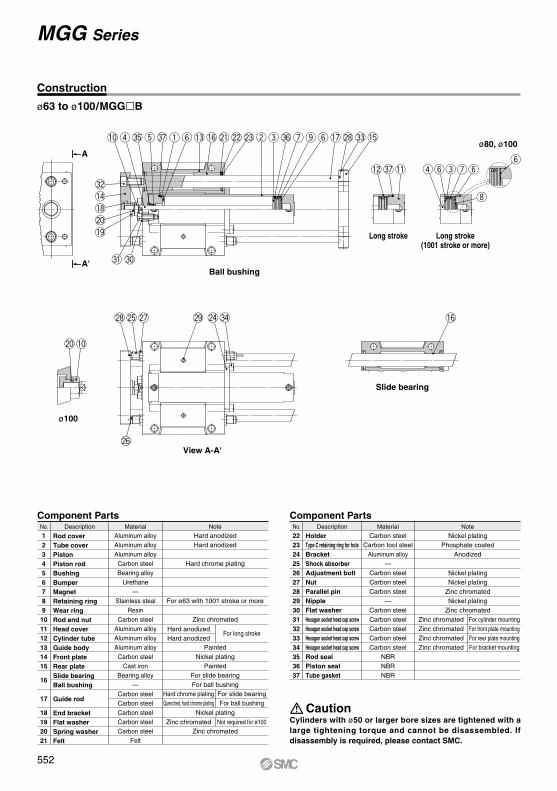
ø63 to ø100/MGGB
Construction
Component Parts Component Parts
Caution
A
A'
ø100
View A-A'
Slide bearing
Ball bushing
ø80, ø100
Long stroke(1001 stroke or more)
Long stroke
r#5t#7qy!3!6@1 @2 @3 we#6uoy!7@8#3!5
@6
@8@5@7 @9 @4#4 !6
@0!0
!2#7!1 ryeuy
i
y
!0
#2!4!8@0!9
#1 #0
MGG Series
Cylinders with ø50 or larger bore sizes are tightened with a large tightening torque and cannot be disassembled. If disassembly is required, please contact SMC.
22232425262728293031323334353637
HolderType C retaining ring for holeBracketShock absorberAdjustment boltNutParallel pinNippleFlat washerHexagon socket head cap screwHexagon socket head cap screwHexagon socket head cap screwHexagon socket head cap screwRod sealPiston sealTube gasket
Carbon steelCarbon tool steel
Aluminum alloy—
Carbon steelCarbon steelCarbon steel
—Carbon steelCarbon steelCarbon steelCarbon steelCarbon steel
NBRNBRNBR
Nickel platingPhosphate coated
Anodized
Nickel platingNickel plating
Zinc chromatedNickel plating
Zinc chromatedFor cylinder mountingFor front plate mountingFor rear plate mountingFor bracket mounting
Zinc chromatedZinc chromatedZinc chromatedZinc chromated
Hard anodizedHard anodized
Hard chrome plating
For ø63 with 1001 stroke or more
Zinc chromated
PaintedNickel plating
PaintedFor slide bearingFor ball bushing
Nickel plating
Zinc chromated
Hard anodizedHard anodized
Hard chrome platingQuenched, hard chrome plating
For slide bearingFor ball bushing
For long stroke
Zinc chromated Not required for ø100
Aluminum alloyAluminum alloyAluminum alloyCarbon steelBearing alloy
Urethane—
Stainless stealResin
Carbon steelAluminum alloyAluminum alloyAluminum alloyCarbon steel
Cast ironBearing alloy
—Carbon steelCarbon steelCarbon steelCarbon steelCarbon steel
Felt
123456789101112131415
16
17
18192021
Rod coverTube coverPistonPiston rodBushingBumperMagnetRetaining ringWear ringRod end nutHead coverCylinder tubeGuide bodyFront plateRear plateSlide bearingBall bushing
Guide rod
End bracketFlat washerSpring washerFelt
DescriptionNo. Material Note DescriptionNo. Material Note
552
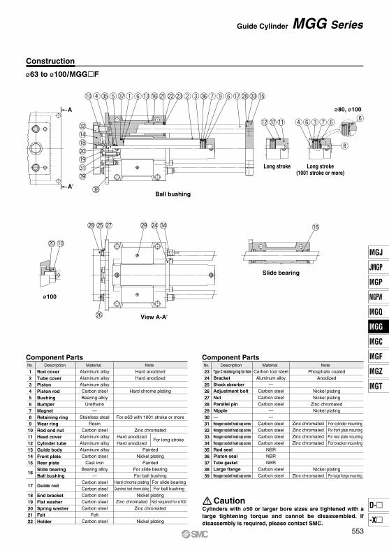
ø63 to ø100/MGGF
Construction
Cylinders with ø50 or larger bore sizes are tightened with a large tightening torque and cannot be disassembled. If disassembly is required, please contact SMC.
A
A'
ø100
View A-A'
Slide bearing
Ball bushing
ø80, ø100
Long stroke(1001 stroke or more)
Long stroke
!0r
@0 !0
#5t
@8 @5 @7 @9 @4 #4 !6
#7qy!3!6@1@2@3we#6uoy!7@8#3!5
!2#7!1
i
ryeuyy
#2!4!8@0!9#1#9
#8
@6
Caution
MGG SeriesGuide Cylinder
123456789101112131415
16
17
1819202122
Rod coverTube coverPistonPiston rodBushingBumperMagnetRetaining ringWear ringRod end nutHead coverCylinder tubeGuide bodyFront plateRear plateSlide bearingBall bushing
Guide rod
End bracketFlat washerSpring washerFeltHolder
Aluminum alloyAluminum alloyAluminum alloyCarbon steelBearing alloy
Urethane—
Stainless stealResin
Carbon steelAluminum alloyAluminum alloyAluminum alloyCarbon steel
Cast ironBearing alloy
—Carbon steelCarbon steelCarbon steelCarbon steelCarbon steel
FeltCarbon steel
Hard anodizedHard anodized
Hard chrome plating
For ø63 with 1001 stroke or more
Zinc chromated
PaintedNickel plating
PaintedFor slide bearingFor ball bushing
Nickel plating
Zinc chromated
Nickel plating
Hard anodizedHard anodized
Hard chrome platingQuenched, hard chrome plating
For slide bearingFor ball bushing
For long stroke
Zinc chromated Not required for ø100
2324252627282930313233343536373839
Type C retaining ring for holeBracketShock absorberAdjustment boltNutParallel pinNipple—Hexagon socket head cap screwHexagon socket head cap screwHexagon socket head cap screwHexagon socket head cap screwRod sealPiston sealTube gasketLarge flangeHexagon socket head cap screw
Carbon tool steelAluminum alloy
—Carbon steelCarbon steelCarbon steel
——
Carbon steelCarbon steelCarbon steelCarbon steel
NBRNBRNBR
Carbon steelCarbon steel
Phosphate coatedAnodized
Nickel platingNickel plating
Zinc chromatedNickel plating
Nickel plating
For cylinder mountingFor front plate mountingFor rear plate mountingFor bracket mounting
Zinc chromatedZinc chromatedZinc chromatedZinc chromated
Zinc chromated For large flange mounting
Component Parts Component PartsNoteMaterialDescriptionNo. NoteMaterialDescriptionNo.
553
MGJ
JMGP
MGP
MGPW
MGQ
MGG
MGC
MGF
MGZ
MGT
D-
-X
MGG
U
AP
V
EZ + Stroke
AL
W
I
AE
R
AAJ
C D
øT
BøS
Q
AB
X Y + Stroke
A
AC AD
K L
MN
Bracket(Refer to the table at right.)
8 x AF
4 x øF through, counterbore øGBottom 4 x H
4 x O
2 x P(Rc, NPT, G)
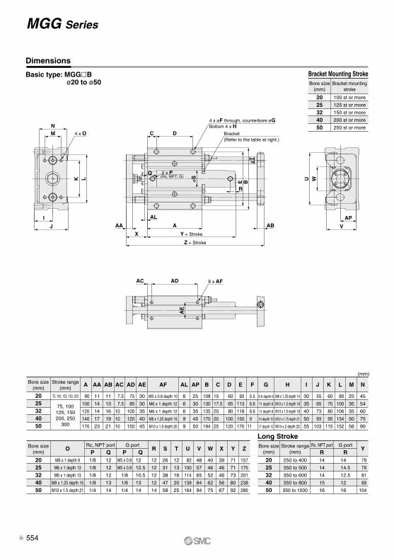
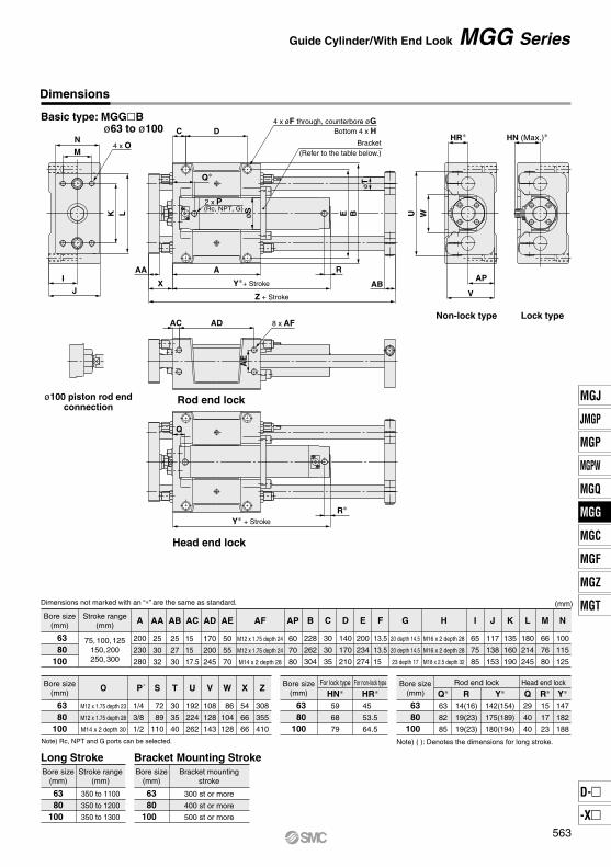
Bore size(mm)
2025324050
Stroke range(mm)
75, 100, 125, 150, 200
75, 100125, 150200, 250
300
A
90
100
120
140
170
AA
11
14
14
17
23
AB
11
13
16
19
21
AC
7.5
7.5
10
10
10
AD
75
85
100
120
150
AE
30
30
35
40
45
AF
M5 x 0.8 depth 10
M6 x 1 depth 12
M6 x 1 depth 12
M8 x 1.25 depth 16
M10 x 1.5 depth 20
AP
25
30
35
45
50
AL
6
6
6
9
9
B
108
130
135
170
194
C
15
17.5
20
20
25
D
60
65
80
100
120
E
92
113
118
150
170
F
5.5
6.6
6.6
9
11
G
9.5 depth 6
11 depth 8
11 depth 8
14 depth 10
17 depth 12
H
M8 x 1.25 depth 14
M10 x 1.5 depth 18
M10 x 1.5 depth 18
M12 x 1.75 depth 21
M14 x 2 depth 25
I
30
35
40
50
55
J
55
65
73
93
103
K
60
70
80
95
115
L
80
100
106
134
152
M
25
35
35
50
56
N
45
54
60
75
90
(mm)
Bore size(mm)
2025324050
100 st or more
125 st or more
150 st or more
200 st or more
250 st or more
Bracket mountingstroke
Bracket Mounting Stroke
Bore size(mm)
2025324050
250 to 400
350 to 500
350 to 600
350 to 800
350 to 1000
14
14
14
15
16
Rc, NPT port
RG port
R14
14.5
12.5
12
16
Y
79
79
81
89
104
Stroke range(mm)
Long StrokeBore size
(mm)
2025324050
O
M6 x 1 depth 9
M6 x 1 depth 13
M6 x 1 depth 13
M8 x 1.25 depth 16
M10 x 1.5 depth 21
P1/8
1/8
1/8
1/8
1/4
Q12
12
12
13
14
Q12
12.5
10.5
13
14
PM5 x 0.8
M5 x 0.8
1/8
1/8
1/4
Rc, NPT port G portR
12
12
12
12
14
S
26
31
38
47
58
T
12
13
16
20
25
U
82
100
114
138
164
V
48
57
65
84
94
W
40
46
52
62
75
X
39
46
46
56
67
Y
71
71
73
80
92
Z
157
175
201
238
285
Basic type: MGGB
Dimensions
ø20 to ø50
MGG Series
554A

Bore size(mm)
6380
100
O
M12 x 1.75 depth 23
M12 x 1.75 depth 28
M14 x 2 depth 30
P
1/4
3/8
1/2
∗ Q
29
40
40
R
14
19
19
S
72
89
110
T
30
35
40
U
192
224
262
V
108
128
143
W
86
104
128
X
54
66
66
Y
107
131
131
Z
308
355
410
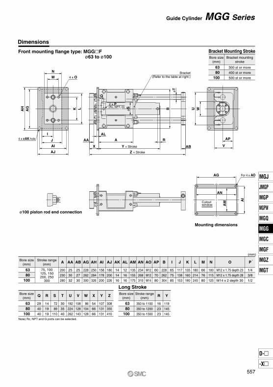
Bore size(mm)
6380
100
300 st or more
400 st or more
500 st or more
Bracket mountingstroke
Bore size(mm)
6380
100
350 to 1100
350 to 1200
350 to 1300
R
16
23
23
Y
119
145
145
Stroke range(mm)
Long Stroke
Bracket Mounting Stroke
Bore size(mm)
6380
100
Stroke range(mm)
75, 100125, 150200, 250
300
A
200
230
280
AA
25
30
32
AB
25
27
30
AC
15
15
17.5
AD
170
200
245
AE
50
55
70
AF
M12 x 1.75 depth 24
M12 x 1.75 depth 24
M14 x 2 depth 28
AP
60
70
80
B
228
262
304
C
30
30
35
D
140
170
210
E
200
234
274
F
13.5
13.5
15
G
20 depth 14.5
20 depth 14.5
23 depth 17
H
M16 x 2 depth 28
M16 x 2 depth 28
M18 x 2.5 depth 32
I
65
75
85
J
117
138
153
K
135
160
190
L
180
214
245
M
66
76
80
N
100
115
125
(mm)
Note) Rc, NPT and G ports can be selected.
ø100 piston rod end connection
Y + Stroke
Z + Stroke
AA A R
X AB
C D
E B
øT
MN
K L
I
J
U W
AP
V
AC AD
øS
Q
AE
Bracket(Refer to the table at right.)
4 x øF through, counterbore øGBottom 4 x H
2 x P(Rc, NPT, G)
8 x AF
4 x O
Basic type: MGGB
Dimensions
ø63 to ø100
MGG SeriesGuide Cylinder
555
MGJ
JMGP
MGP
MGPW
MGQ
MGG
MGC
MGF
MGZ
MGT
D-
-X
MGG

AP
V
WUøS
Q
R
BøT
ABA
Y + Stroke
Z + Stroke
X
AA
I
J
K L
M
N
AG
AG
AI
AJ
AH
AL
AI
AN
AM
Bracket(Refer to the table at right.)
Mounting dimensions
4 x O
For 4 x AO
4 x øAK hole
2 x P(Rc, NPT, G)
Cutoutwindow
Bore size(mm)
2025324050
100 st or more
125 st or more
150 st or more
200 st or more
250 st or more
Bracket mountingstroke
Bracket Mounting Stroke
Dimensions
Front mounting flange type: MGGFø20 to ø50
MGG Series
Bore size(mm)
2025324050
Stroke range(mm)
75, 100, 125, 150, 200
75, 100125, 150200, 250
300
A
90
100
120
140
170
AA
11
14
14
17
23
AB
11
13
16
19
21
AG
112
134
134
170
190
AH
125
150
150
186
210
AI
82
92
102
134
140
AJ
95
108
118
150
160
AK
6.6
9
9
9
11
AL
9
9
9
12
12
AM
65
75
85
105
115
AN
115
135
140
175
200
AO
M6
M8
M8
M8
M10
AP
25
30
35
45
50
B
108
130
135
170
194
I
30
35
40
50
55
J
55
65
73
93
103
K
60
70
80
95
115
L
80
100
106
134
152
M
25
35
35
50
56
N
45
54
60
75
90
O
M6 x 1 depth 9
M6 x 1 depth 13
M6 x 1 depth 13
M8 x 1.25 depth 16
M10 x 1.5 depth 21
(mm)
Bore size(mm)
2025324050
R
12
12
12
12
14
S
26
31
38
47
58
T
12
13
16
20
25
U
82
100
114
138
164
V
48
57
65
84
94
W
40
46
52
62
75
X
39
46
46
56
67
Y
71
71
73
80
92
Z
157
175
201
238
285
Bore size(mm)
2025324050
250 to 400
350 to 500
350 to 600
350 to 800
350 to 1000
Y
79
79
81
89
104
Stroke range(mm)
Long Stroke
14
14
14
15
16
Rc, NPT port
RG port
R14
14.5
12.5
12
16
P1/8
1/8
1/8
1/8
1/4
Q12
12
12
13
14
Q12
12.5
10.5
13
14
PM5 x 0.8
M5 x 0.8
1/8
1/8
1/4
Rc, NPT port G port
556A
Bore size(mm)
6380
100
Q
29
40
40
R
14
19
19
S
72
89
110
T
30
35
40
U
192
224
262
V
108
128
143
W
86
104
128
X
54
66
66
Y
107
131
131
Z
308
355
410
Bore size(mm)
6380
100
350 to 1100
350 to 1200
350 to 1300
R
16
23
23
Y
119
145
145
Stroke range(mm)
Long Stroke
Bore size(mm)
6380
100
300 st or more
400 st or more
500 st or more
Bracket mountingstroke
Bracket Mounting Stroke
Bore size(mm)
6380
100
Stroke range(mm)
75, 100125, 150200, 250
300
A
200
230
280
AA
25
30
32
AB
25
27
30
AG
228
262
300
AH
250
284
326
AI
158
178
200
AJ
180
200
226
AK
14
14
16
AL
12
16
16
AM
135
155
175
AN
234
268
310
AO
M12
M12
M14
AP
60
70
80
B
228
262
304
I
65
75
85
J
117
138
153
K
135
160
190
L
180
214
245
M
66
76
80
N
100
115
125
(mm)
O
M12 x 1.75 depth 23
M12 x 1.75 depth 28
M14 x 2 depth 30
P
1/4
3/8
1/2
∗
Note) Rc, NPT and G ports can be selected.
Y + Stroke
Z + Stroke
AA
V
AN
AG
X AB
A
Q
I
J
AI
AJ
R
M
N
AH
AG K øS
øT
L UB
AI
AM
W
Mounting dimensions
ø100 piston rod end connection
ALAP
Bracket(Refer to the table at right.)4 x O
For 4 x AO
(Rc, NPT, G)2 x P
4 x øAK hole
Dimensions
Front mounting flange type: MGGFø63 to ø100
Cutoutwindow
MGG SeriesGuide Cylinder
557
MGJ
JMGP
MGP
MGPW
MGQ
MGG
MGC
MGF
MGZ
MGT
D-
-X
MGG
L NH M9BWB 32Guide Cylinder
MGG 100
Lock positionCylinder stroke (mm)
Refer to “Standard Stroke” on page 559.
C
Auto switch mounting bracket Note)
Note) This symbol is indicated when the D-A9 or M9 type auto switch is specified. This mounting bracket does not apply to other auto switches (D-C7 and H7, etc.) (Nil)
20253240
506380
100
50 mm
63 mm
80 mm
100 mm
20 mm
25 mm
32 mm
40 mm
Rc
NPT
G
Non-lock type
Lock type
Head end lock
Rod end lockNL
HR
BF
How to Order
Bearing type
Mounting type
Bore size
Basic type
Front mounting flange type
Nil
TNTF
Port thread type
Made to Order Refer to page 560 for details.
Number of auto switchesNilSn
2 pcs.
1 pc.
“n” pcs.
Auto switch
Manual release type
∗ For the applicable auto switch model, refer to the table below.
Nil Without auto switch(Built-in magnet)
∗ Lead wire length symbols: 0.5 m ·······Nil (Example) M9NW 1 m ······· M (Example) M9NWM 3 m ······· L (Example) M9NWL 5 m ······· Z (Example) M9NWZ None······· N (Example) H7CN
∗ Solid state auto switches marked with “ ” are produced upon receipt of order.
∗ Since there are other applicable auto switches than listed, refer to page 570 for details.∗ For details about auto switches with pre-wired connector, refer to pages 1192 and 1193.∗ D-A9(V)/M9(V)/M9W(V)/M9A(V) auto switches are shipped together (not assembled).
(Only switch mounting brackets are assembled at the time of shipment.)
When using auto switches shown inside ( ), stroke end detection may not be possible depending on the One-touch fitting or speed controller model. Please contact SMC in this case.
Caution
∗1 Water resistant type auto switches can be mounted on the above models, but in such case SMC cannot guarantee water resistance. Consult with SMC regarding water resistant types with the above model numbers.
∗2 1 m type lead wire is only applicable to D-A93.
Guide Cylinder/With End Lock
MGG Seriesø20, ø25, ø32, ø40, ø50, ø63, ø80, ø100
Applicable Auto Switches/Refer to pages 1119 to 1245 for further information on auto switches.
ML
Slide bearing
Ball bushing bearing
Yes
Yes
Yes
Yes
Yes
Type Special function Electricalentry
—
100 V100 V or less100 V, 200 V200 V or less
—24 V or less
—
Wiring (Output)
Auto switch model
DC
24 V
24 V
5 V,12 V
12 V
5 V,12 V
12 V
5 V,12 V
12 V
5 V ,12 V
5 V
12 V
—
AC
Lead wire length (m)
0.5(Nil)
—
3(L)
1(M)
—————————
—
——————
5(Z)
—
———
None(N)
—————————————————
—
—————
—
—
———————
Applicable loadPre-wiredconnector
IC circuit
—
IC circuit
—
IC circuit
—
IC circuitIC
circuit—
IC circuit
—
IC circuit—
Relay,PLC
Relay,PLC
Auto switch modelApplicable bore (mm)ø20 to ø63 ø80, ø100
In-linePerpendicularM9N—
M9P—
M9B—
H7CM9NW
—M9PW
—M9BW
—M9NA∗1
M9PA∗1
M9BA∗1
—H7NF
A96
A93A90
C73CC80C
—G59—
G5P—
K59——
G59W—
G5PW—
K59W———
G5BA∗1
G59F
—
——
——
M9NV—
M9PV—
M9BV——
M9NWV—
M9PWV—
M9BWV—
M9NAV∗1
M9PAV∗1
M9BAV∗1
——
A96V
A93V∗2
A90V—————
B54B64
B59W
—
—
—
—
—
In-lineIndic
ator
light
Ree
d a
uto
sw
itch
So
lid s
tate
au
to s
wit
ch
Diagnostic indication(2-color indicator)
With diagnostic output (2-color indicator)
Diagnostic indication(2-color indicator)
Water resistant(2-color indicator)
Connector
Connector
Grommet
Grommet
Grommet
Grommet
No
No
No
3-wire (NPN)
3-wire (PNP)
3-wire (NPN)
3-wire (NPN)
4-wire (NPN)
3-wire (PNP)
3-wire (PNP)
2-wire
2-wire
2-wire
2-wire
3-wire(NPN equivalent)
558
Symbol Rubber bumper
Specifications
20
215
25
330
32
550
40
860
63
2140
50
1340
80
3450
100
5390
RB1007
MGG20
5.88
7
70
4.22
6.860
RB1412
MGG25, 32
19.6
12
45
6.86
15.98
RB2015
MGG40, 50, 63
58.8
15
25
8.34
20.5
RB2725
MGG80, 100
147
25
10
8.83
20.01
5
–10 to 80
MGG20
20
MGG25
25
MGG32
32
MGG40
40
MGG63
63
MGG50
50
MGG80
80
MGG100
100CDBG1BN XC70
250, 300, 350, 400
350, 400, 450, 500
350, 400, 450, 500, 600
350, 400, 450, 500, 600, 700, 800
350, 400, 450, 500, 600, 700, 800, 900, 1000
350, 400, 450, 500, 600, 700, 800, 900, 1000, 1100
350, 400, 450, 500, 600, 700, 800, 900, 1000, 1100, 1200
350, 400, 450, 500, 600, 700, 800, 900, 1000, 1100, 1200, 1300
Model (Bearing type)
MGGM(Slide bearing)MGGL(Ball bushing bearing)
Bore size (mm)
20
25
32
40
50
63
80
100
Standard stroke (mm)
75, 100, 125, 150, 200
75, 100, 125, 150,
200, 250, 300
Long stroke (mm)
Standard Stroke
∗ Intermediate strokes and short strokes other than the above are produced upon receipt of order.
SpecificationsModel
Basic cylinder
Bore size (mm)
Action
Fluid
Proof pressure
Maximum operating pressure
Minimum operating pressure
Ambient and fluid temperature
Piston speed
Cushion
Stroke adjusting range (One side)[Built-in adjusting bolts (2 pcs.)]
Base cylinder lubrication
Stroke length tolerance
Non-rotatingaccuracy
Piping port size (Rc, NPT, G)
Basic cylinder
Guide unit
Slide bearing
Ball bushing bearing
∗ When the cylinder is retracted (initial value), the non-rotating accuracy without loads or deflection of the guide rods will be below the values shown in the table above as a guideline.
0 to –10 mm 0 to –15 mm
Double acting
Air
1.5 MPa
1.0 MPa
0.15 MPa (Horizontal with no load)
–10 to 60°C
Rubber bumper
Built-in shock absorbers (2 pcs.)
Non-lube
mm(1000 st or less), mm(1001 st or more)+1.9+0.2
+2.3+0.2
50 to 700 mm/s50 to 1000 mm/s
1/8 1/4 3/8 1/2
∗ It denotes the values at the maximum energy absorption per one cycle. Therefore, the operating frequency can be increased according to the energy absorption.
Shock Absorber SpecificationsShock absorber model
Applicable guide cylinder
Maximum energy absorption (J)
Stroke absorption (mm)
Maximum collision speed (m/s)
Max. operating frequency (cycle/min)
Ambient temperature range ( C)
Spring force (N)Extended
Retracted
∗
Lock SpecificationsBore size (mm)
Holding force (Max.) (N)
Lock position
Backlash
Manual release∗ Adjust switch positions for operation at both the stroke end and backlash (2 mm) movement positions.
Head end, Rod end
2 mm or less
Non-lock type, Lock type
Bore size Stroke Lock position Auto switchManual releasePort thread type
Guide Cylinder/With End Look MGG Series
±0.07°
±0.06°
±0.06°
±0.05°
±0.06°
±0.04°
±0.05°
±0.04°
±0.04°
±0.04°
±0.04°
±0.03°
±0.04°
±0.03°
±0.03°
±0.02°
559
MGJ
JMGP
MGP
MGPW
MGQ
MGG
MGC
MGF
MGZ
MGT
D-
-X
MGG
A
OUT IN
-XC79
(kg)
20 25 32 40
18.58
1.265
13.09
0.948
8.29
0.679
5.23
0.509
3.09
0.326
1.61
0.203
1.14
0.135
0.69
0.109
50 63 80 100
20 25 32 40 50
37.46
45.98
36.36
44.89
1.48
0.26
0.548
1.15
1.23
1.31
1.39
26.32
33
25.61
32.29
1.11
0.19
0.384
0.8
0.88
0.9
0.97
16.6
20.58
16.22
20.2
0.82
0.1
0.269
0.44
0.48
0.51
0.54
11.63
14.17
11.36
13.89
0.61
0.06
0.061
0.26
0.3
0.31
0.34
7.19
9.38
7.17
9.37
0.4
0.03
0.031
0.17
0.21
0.19
0.23
3.84
4.87
3.36
4.39
0.25
0.02
0.019
0.08
0.1
0.12
0.14
2.82
3.79
2.79
3.75
0.17
0.01
0.018
0.07
0.08
0.08
0.1
1.72
2.44
1.71
2.42
0.14
0.01
0.011
0.05
0.07
0.07
0.09
(kg)
1008063
20
25
32
40
50
63
80
100
8
10
12
16
20
20
25
30
OUT
IN
OUT
IN
OUT
IN
OUT
IN
OUT
IN
OUT
IN
OUT
IN
OUT
IN
314
264
491
412
804
691
1260
1060
1960
1650
3120
2800
5030
4540
7850
7150
0.2
62.8
52.8
98.2
82.4
161
138
252
212
392
330
624
560
1010
908
1570
1430
0.3
94.2
79.2
147
124
241
207
378
318
588
495
936
840
1510
1360
2360
2150
0.4
126
106
196
165
322
276
504
424
784
660
1250
1120
2010
1820
3140
2860
0.5
157
132
246
206
402
346
630
530
980
825
1560
1400
2520
2270
3930
3580
0.6
188
158
295
247
482
415
756
636
1180
990
1870
1680
3020
2720
4710
4290
0.7
220
185
344
288
563
484
882
742
1370
1160
2180
1960
3520
3180
5500
5010
0.8
251
211
393
330
643
553
1010
848
1570
1320
2500
2240
4020
3630
6280
5720
0.9
283
238
442
371
724
622
1130
954
1760
1490
2810
2520
4530
4090
7070
6440
1.0
314
264
491
412
804
691
1260
1060
1960
1650
3120
2800
5030
4540
7850
7150
(N)
Bore size(mm)
Rod size(mm)
Operatingdirection
Piston area(mm2)
Operating pressure (MPa)
Theoretical Output
Note) Theoretical output (N) = Pressure (MPa) x Piston area (mm2)
Weight
Weight of Moving Parts
Symbol Specifications
Bas
ic w
eig
ht
Bore size (mm)
LB Type (Ball bushing bearing, Basic type)
LF Type (Ball bushing bearing, Front mounting flange type)
MB Type (Slide bearing, Basic type)
MF Type (Slide bearing, Front mounting flange type)
Additional weight per each 50 mm of stroke
Additional weight for long stroke
Additional weight with bracket
Non-lock type (N)
Lock type (L)
Non-lock type (N)
Lock type (L)
Head end lock (H)
Rod end lock (R)
Addit
ional
weigh
t of lo
ck un
it
Calculation: (Example) MGGLB32-500-HN (Ball bushing type) (Basic type, ø32, 500 st, With bracket)• Standard weight ······················· 3.84 (LB type) • Additional weight for long stroke ······ 0.02• Additional weight for stroke ······ 0.25/50 st • Additional weight with bracket ·········· 0.019• Stroke ······································· 500 st3.84 + 0.25 x 500/50 + 0.02 + 0.019+ 0.08 = 6.459 kg
• Additional weight of lock unit ············ 0.08(Head side, Non-lock type)
Bore size (mm)
Moving parts basic weight
Additional weight by each 50 mm of stroke
Calculating weight of moving parts (Example) MGGLB32-500-HN• Moving parts basic weight ······· 1.61• Additional weight for stroke ······ 0.203/50 st• Stroke ······································· 500 st1.61 + 0.203 x 500/50 = 3.64 kg
Refer to pages 542 to 550 for the allowable end load and deflection, as well as the allowable eccentric load.
Machining tapped hole, drilled hole and pin hole additionally
MGG Series
Made to Order Specifications(For details, refer to pages 1247 to 1440.)
560
Head end lockFront mounting flange type
@9 !4q t #1!1 r y e #0 i !2 !0 u o !3
!9
Manual release (Lock type)
Manual release (Non-lock type)
ø20 to ø63 ø80, ø100
ø20 to ø63 ø80, ø100
Rod end lock (Base cylinder only)ø40 to ø100ø80, ø100
!7
#2
!6
@5 @4 @3 @6 @1 @8
@8
@7yw
@0@2
!8
!5
∗ Since the guide unit, front plate and rear plate figure are the same as the standard type, refer to pages 551 to 553.
ø20 to ø100/MGG
123456789101112131415161718192021222324
25
26272829303132
Kit no.
CBG1N20-PSCBG1N25-PSCBG1N32-PSCBG1N40-PS
Bore size (mm) Contents
20253240
Construction
Component Parts Component Parts
Replacement Parts: Seal Kit
Description Material
Aluminum alloy
Aluminum alloy
Aluminum alloy
Carbon steel
Bearing alloy
Urethane
Urethane
—
Stainless steel
Resin
Rolled steel
NBR
Aluminum alloy
Aluminum alloy
Carbon steel
Bearing alloy
Stainless steel
Urethane
Chromium molybdenum steel
Aluminum die-casted
Carbon steel
Synthetic rubber
Zinc die-casted
Chromium molybdenum steel
Steel wire
No. Note
White hard anodized
White hard anodized
Chromated
Description is “Bumper” for ø63 and larger
ø40 or larger: Same as Bumber A
Not required for ø80, ø100
Hard chrome plated, Heat treated
Black zinc chromated
For non-lock type
Rod cover
Tube cover
Piston
Piston rod
Bushing
Bumper A
Bumper B
Magnet
Retaining ring
Wear ring
Rod end nut
Piston gasket
Head cover
Cylinder tube
Lock piston
Lock bushing
Lock spring
Bumper
Hexagon socke thead cap screw
Cap A
Cap B
Rubber cap
M/O knob
M/O bolt
M/O spring
Hard chrome plated ø20, ø25 are stainless steel
Nickel plated ø100 is carbon steel
White hard anodized
Hard anodized
For head side locking typeand long stroke
Black painted
Oxide film treated
Black painted
Black zinc chromated, Red painted
Zinc chromated
For non-lock type
For lock type
For lock type
For lock type
For lock typeø20, ø25, ø32: Stainless steel
Stopper ring
Piston holder
Seal retainer
Rod seal
Piston seal
Tube gasket
Lock piston seal
Carbon steel
Urethane
Rolled steel
NBR
NBR
NBR
NBR
Zinc chromated
Used for ø40 and larger
Used for ø80 and ø100
∗ Since the guide unit parts are the same as the standard type, refer to pages 551 to 553.
For lock type
NoteDescriptionNo. Material
Set of nos. above @9, #0, #1, #2.
∗ Seal kit includes @9 to #2. Order the seal kit, based on each bore size.
∗ Seal kit includes a grease pack (10 g).Order with the following part number when only the grease pack is needed.Grease pack part no.: GR-S-010 (10 g)
CautionBasic cylinders with a bore size of ø50 cannot be disassembled. (Cylinders with ø50 or larger bore sizes are tightened with a large tightening torque and cannot be disassembled. Please contact SMC when disassemble is required.)
Guide Cylinder/With End Look MGG Series
561
MGJ
JMGP
MGP
MGPW
MGQ
MGG
MGC
MGF
MGZ
MGT
D-
-X
MGG
A

APV
øS E
BøT
AE
R∗
Y∗ + Stroke
HR∗
WU
AL
R
AA
C D
AB
Z + Stroke
X Y∗ + Stroke
A
AC AD
HN (Max.)∗
IJ
K L
MN
Q∗
Head end lock
Rod end lock
Lock typeNon-lock type
2 x P(Rc, NPT, G)
8 x AF
Bracket(Refer to the table below.)
4 x øF through, counterbore øGBottom 4 x H
4 x O
Q
Bore size(mm)
2025324050
250 to 400
350 to 500
350 to 600
350 to 800
350 to 1000
Stroke range(mm)
Long StrokeBore size
(mm)
2025324050
100 st or more
125 st or more
150 st or more
200 st or more
250 st or more
Bracket mountingstroke
Bracket Mounting Stroke
Bore size(mm)
2025324050
O
M6 x 1 depth 9
M6 x 1 depth 13
M6 x 1 depth 13
M8 x 1.25 depth 16
M10 x 1.5 depth 21
P
1/8
1/8
1/8
1/8
1/4
∗ S
26
31
38
47
58
T
12
13
16
20
25
U
82
100
114
138
164
V
48
57
65
84
94
W
40
46
52
62
75
X
39
46
46
56
67
Z
157
175
201
238
285
Bore size(mm)
Rod end lock Head end lock
2025324050
Q∗
38.5
39
40
41
47
R12 (14)
12 (14)
12 (14)
12 (15)
14 (16)
Y∗
98 (106)
98 (106)
101 (109)
109 (118)
125 (137)
Q12
12
12
13
14
R∗
11
11
11
11
16
Y∗
95
95
97
111
128
Note) ( ): Denotes the dimensions for long stroke.
Bore size(mm)
For lock type For non-lock type
2025324050
HN∗
37
40
43
52.5
58.5
HR∗
25.3
28.3
31.3
38.3
44.5
Bore size(mm)
2025324050
Stroke range(mm)
75, 100, 125, 150, 200
75, 100125, 150200, 250
300
B
108
130
135
170
194
C
15
17.5
20
20
25
D
60
65
80
100
120
E
92
113
118
150
170
F
5.5
6.6
6.6
9
11
G
9.5 depth 6
11 depth 8
11 depth 8
14 depth 10
17 depth 12
H
M8 x 1.25 depth 14
M10 x 1.5 depth 18
M10 x 1.5 depth 18
M12 x 1.75 depth 21
M14 x 2 depth 25
I
30
35
40
50
55
J
55
65
73
93
103
K
60
70
80
95
115
L
80
100
106
134
152
M
25
35
35
50
56
N
45
54
60
75
90
(mm)
AA
11
14
14
17
23
AB
11
13
16
19
21
AC
7.5
7.5
10
10
10
AD
75
85
100
120
150
AE
30
30
35
40
45
AF
M5 x 0.8 depth 10
M6 x 1 depth 12
M6 x 1 depth 12
M8 x 1.25 depth 16
M10 x 1.5 depth 20
AP
25
30
35
45
50
AL
6
6
6
9
9
Dimensions not marked with an “∗” are the same as standard.
Note) Rc, NPT and G ports can be selected.
A
90
100
120
140
170
ø20 to ø50Basic type: MGGB
Dimensions
MGG Series
562A
Bore size(mm)
6380
100
350 to 1100
350 to 1200
350 to 1300
Stroke range(mm)
Long StrokeBore size
(mm)
6380
100
300 st or more
400 st or more
500 st or more
Bracket mountingstroke
Bracket Mounting Stroke
Bore size(mm)
63 80100
X
54
66
66
Z
308
355
410
O
M12 x 1.75 depth 23
M12 x 1.75 depth 28
M14 x 2 depth 30
P
1/4
3/8
1/2
∗ S
72
89
110
T
30
35
40
U
192
224
262
V
108
128
143
W
86
104
128
Bore size(mm)
6380
100
Stroke range(mm)
75, 100, 125150, 200250, 300
A
200
230
280
B
228
262
304
C
30
30
35
D
140
170
210
E
200
234
274
F
13.5
13.5
15
G
20 depth 14.5
20 depth 14.5
23 depth 17
H
M16 x 2 depth 28
M16 x 2 depth 28
M18 x 2.5 depth 32
I
65
75
85
J
117
138
153
K
135
160
190
L
180
214
245
M
66
76
80
N
100
115
125
(mm)
AA
25
30
32
AB
25
27
30
AC
15
15
17.5
AD
170
200
245
AE
50
55
70
AF
M12 x 1.75 depth 24
M12 x 1.75 depth 24
M14 x 2 depth 28
AP
60
70
80
Dimensions not marked with an “∗” are the same as standard.
Bore size(mm)
For lock type For non-lock type
63 80100
HN∗
59
68
79
HR∗
45
53.5
64.5
Bore size(mm)
Rod end lock Head end lock
6380
100
Q∗
63
82
85
R14(16)
19(23)
19(23)
Y∗
142(154)
175(189)
180(194)
Q29
40
40
R∗
15
17
23
Note) ( ): Denotes the dimensions for long stroke.
Y∗
147
182
188
Note) Rc, NPT and G ports can be selected.
Dimensions
Basic type: MGGBø63 to ø100
Guide Cylinder/With End Look MGG Series
Y∗+ Stroke
HR∗ HN (Max.)∗
Y∗ + Stroke
Z + Stroke
AA A
X AB
C
Q∗
R
D
AE
øS
øT
BE
8 x AF
M
N
K L
I
J
4 x O
2 x P
U W
AP
V
AC
Q
R∗
AD
Rod end lock
Head end lock
Non-lock type
ø100 piston rod endconnection
Lock type
(Rc, NPT, G)
4 x øF through, counterbore øGBottom 4 x H
Bracket(Refer to the table below.)
563
MGJ
JMGP
MGP
MGPW
MGQ
MGG
MGC
MGF
MGZ
MGT
D-
-X
MGG
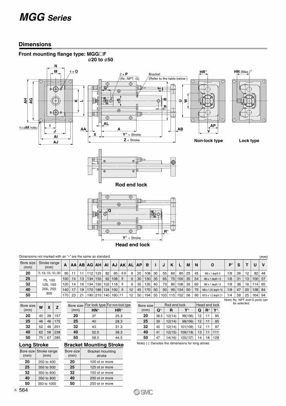
Head end lock
VAP
WUøS
øT
B
R
HR∗NM
JI AL
AA AB
Z + Stroke
X Y∗ + Stroke
A
Y∗ + Stroke
HN (Max.)∗K LAG
AIAJ
AH
Q∗
2 x P(Rc, NPT, G)
Lock typeNon-lock type
Bracket(Refer to the table below.)
4 x O
Rod end lock
4 x øAK holes
Q
R∗
Bore size(mm)
2025324050
250 to 400
350 to 500
350 to 600
350 to 800
350 to 1000
Stroke range(mm)
Long StrokeBore size
(mm)
2025324050
100 st or more
125 st or more
150 st or more
200 st or more
250 st or more
Bracket mountingstroke
Bracket Mounting Stroke
Bore size(mm)
2025324050
W
40
46
52
62
75
X
39
46
46
56
67
Z
157
175
201
238
285
Bore size(mm)
Rod end lock Head end lock
2025324050
Q∗
38.5
39
40
41
47
R12(14)
12(14)
12(14)
12(15)
14(16)
Y∗
98(106)
98(106)
101(109)
109(118)
125(137)
Q12
12
12
13
14
R∗
11
11
11
11
16
Y∗
95
95
97
111
128
Note) ( ): Denotes the dimensions for long stroke.
Bore size(mm)
2025324050
Stroke range(mm)
75, 100, 125, 150, 200
75, 100125, 150200, 250
300
A
90
100
120
140
170
AK
6.6
9
9
9
11
AL
9
9
9
12
12
AP
25
30
35
45
50
B
108
130
135
170
194
I
30
35
40
50
55
J
55
65
73
93
103
K
60
70
80
95
115
L
80
100
106
134
152
M
25
35
35
50
56
N
45
54
60
75
90
O
M6 x 1 depth 9
M6 x 1 depth 13
M6 x 1 depth 13
M8 x 1.25 depth 16
M10 x 1.5 depth 21
P
1/8
1/8
1/8
1/8
1/4
∗ S
26
31
38
47
58
T
12
13
16
20
25
U
82
100
114
138
164
V
48
57
65
84
94
AA
11
14
14
17
23
AB
11
13
16
19
21
AG
112
134
134
170
190
AH
125
150
150
186
210
AI
82
92
102
134
140
AJ
95
108
118
150
160
(mm)Dimensions not marked with an “∗” are the same as standard.
Bore size(mm)
For lock type For non-lock type
2025324050
HN∗
37
40
43
52.5
58.5
HR∗
25.3
28.3
31.3
38.3
44.5
Note) Rc, NPT and G ports can be selected.
Front mounting flange type: MGGF
Dimensions
ø20 to ø50
MGG Series
564A
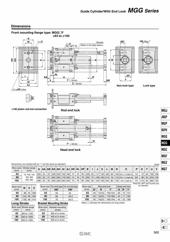
Bore size(mm)
6380
100
350 to 1100
350 to 1200
350 to 1300
Stroke range(mm)
Long StrokeBore size
(mm)
6380
100
300 st or more
400 st or more
500 st or more
Bracket mountingstroke
Bracket Mounting Stroke
Bore size(mm)
6380
100
W
86
104
128
X
54
66
66
Z
308
355
410
Bore size(mm)
Rod end lock Head end lock
6380
100
Q∗
63
82
85
R14(16)
19(23)
19(23)
Y∗
142(154)
175(189)
180(194)
Q29
40
40
R∗
15
17
23
Note) ( ): Denotes the dimensions for long stroke.
Bore size(mm)
For lock type For non-lock type
6380
100
HN∗
59
68
79
HR∗
45
53.5
64.5
Bore size(mm)
6380
100
Stroke range(mm)
75, 100, 125150, 200250, 300
A
200
230
280
B
228
262
304
I
65
75
85
J
117
138
153
K
135
160
190
L
180
214
245
M
66
76
80
N
100
115
125
O
M12 x 1.75 depth 23
M12 x 1.75 depth 28
M14 x 2 depth 30
P
1/4
3/8
1/2
∗ S
72
89
110
T
30
35
40
U
192
224
262
V
108
128
143
AA
25
30
32
AB
25
27
30
AG
228
262
300
AH
250
284
326
AI
158
178
200
AJ
180
200
226
(mm)
AK
14
14
16
AL
12
16
16
AP
60
70
80
Dimensions not marked with an “∗” are the same as standard.
Y∗
147
182
188
Note) Rc, NPT and G ports can be selected.
Dimensions
Guide Cylinder/With End Look MGG Series
Front mounting flange type: MGGFø63 to ø100
Y∗+ Stroke
HR∗ HN (Max.)∗
Y∗ + Stroke
ø100 piston rod end connection
Z + Stroke
AAAL
AX AB
R
BøS
øT
MN
KAG
AH L
IJAIAJ
4 x O
4 x øAK holes
U W
AP
V
R∗
Q
Rod end lock
Head end lock
Non-lock type Lock type
2 x P(Rc, NPT, G)
Bracket(Refer to the table below.)
565
MGJ
JMGP
MGP
MGPW
MGQ
MGG
MGC
MGF
MGZ
MGT
D-
-X
MGG
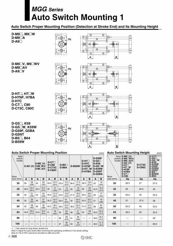
≈Hs
≈Hs
BA
≈Hs
A
A
B
B
≈Hs
BA
(mm)
20
25
32
40
50
63
80
100
D-M9(V)D-M9W(V)D-M9A(V)
A
33
32.5
34
39
46
44.5
—
—
B24
(32)
24.5(32.5)
25(33)
27(36)
32(36)
33.5(45.5)
—
—
D-A9(V)
A
29
28.5
30
35
42
40.5
—
—
B20
(28)
20.5(28.5)
21(29)
23(32)
28(40)
29.5(41.5)
—
—
20.5(28.5)
21(29)
21.5(29.5)
23.5(32.5)
28.5(40.5)
B15.5(22.5)
15(23)
15.5(23.5)
19 (26.5)
22.5(34.5)
B17.5(25.5)
18(26)
18.5(26.5)
20.5(29.5)
25.5(37.5)
B19.5(27.5)
20(28)
20.5(28.5)
22.5(31.5)
27.5(39.5)
B16
(24)
16.5(24.5)
17(25)
19(28)
24(36)
30(42)
—
—
24(36)
29(43)
30(44)
27(39)
32(46)
33(47)
29(41)
—
—
25.5(37.5)
30.5(44.5)
31.5(45.5)
B
29.5
29
30.5
35.5
42.5
41
—
—
A
23.5
23
24.5
29.5
36.5
35
48
47
A
26.5
26
27.5
32
39.5
38
51
50
A
28.5
28
29.5
34.5
41.5
40
—
—
A
25
24.5
26
31
38
36.5
49.5
48.5
A
D-C7D-C80D-C73CD-C80C
D-B5D-B64 D-B59W
D-H7D-H7CD-H7NFD-H7WD-H7BA
D-G59FD-G5D-K59D-G5WD-K59WD-G5NTD-G5BA
D-M9, M9WD-M9AD-A9
D-M9V, M9WVD-M9AVD-A9V
D-G5, K59D-G5W, K59WD-G59F, G5BAD-G5NTD-B5, B64D-B59W
D-H7, H7WD-H7NF, H7BAD-H7CD-C7, C80D-C73C, C80C
MGG Series
Auto Switch Mounting 1
∗( ): Set values for long stroke, double rodNote 1) Adjust the auto switch after confirming the operating conditions in the actual setting.Note 2) The D-H7C cannot be mounted on ø80 and ø100.
Boresize (mm)
Autoswitchmodel
Auto Switch Proper Mounting Position (Detection at Stroke End) and Its Mounting Height
Auto Switch Proper Mounting Position Auto Switch Mounting Height
Boresize (mm)
Autoswitchmodel
20
25
32
40
50
63
80
100
(mm)
26.5
29
32.5
37
42.5
49.5
—
—
Hs
27
29.5
33
37.5
43
50
—
—
Hs Hs
27.5
30
33.5
38
43.5
50.5
59
69.5
D-C73CD-C80C
D-H7C Note 2)
D-G5D-G5WD-K59D-K59WD-G59FD-G5BAD-G5NTD-B5D-B59WD-B64
D-M9(V)D-M9W(V)D-M9A(V)D-A9(V)D-H7D-H7WD-H7NFD-H7BAD-C7D-C80
566A
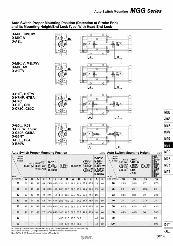
≈Hs
≈Hs
BA
≈Hs
A
A
B
B
≈Hs
BA
Note 1) Adjust the auto switch after confirming the operating conditions in the actual setting.Note 2) Values when “-C” is specified at the end of the cylinder model numberNote 3) The D-H7C cannot be mounted on ø80 and ø100.
Auto Switch Proper Mounting Position (Detection at Stroke End)and Its Mounting Height/End Lock Type: With Head End Lock
Auto Switch Mounting MGG Series
D-M9, M9WD-M9AD-A9
D-M9V, M9WVD-M9AVD-A9V
D-G5, K59D-G5W, K59WD-G59F, G5BAD-G5NTD-B5, B64D-B59W
D-H7, H7WD-H7NF, H7BAD-H7CD-C7, C80D-C73C, C80C
Auto Switch Mounting Height (mm)Auto Switch Proper Mounting Position
Boresize (mm)
Autoswitchmodel
20
25
32
40
50
63
80
100
A
33
33
34
39
46
46
—
—
A
29
29
30
35
42
42
—
—
B
48
48
49
58
68
72
—
—
B
44
44
45
54
64
68
—
—
B B B B B
29.5
29.5
30.5
35.5
42.5
42.5
—
—
44.5
44.5
45.5
54.5
64.5
68.5
—
—
A
23.5
23.5
24.5
29.5
36.5
36.5
46.5
46.5
38.5
38.5
39.5
48.5
58.5
62.5
81.5
87.5
A
26.5
26.5
27.5
32
39.5
39.5
49.5
49.5
41.5
41.5
42.5
51.5
61.5
65.5
84.5
90.5
A
28.5
28.5
29.5
34.5
41.5
41.5
—
—
43.5
43.5
44.5
53.5
63.5
67.5
—
—
A
25
25
26
31
38
38
48
48
40
40
41
50
60
64
83
89
A
D-C7D-C80D-C73CD-C80C
D-B5D-B64 D-B59W
D-H7D-H7CD-H7NFD-H7WD-H7BA
D-G59FD-G5D-K59D-G5WD-K59WD-G5NTD-G5BA
(mm)
Hs
26.5
29
32.5
37
42.5
49.5
—
—
Hs
26.5
29
32.5
37
42.5
49.5
—
—
D-M9(V)D-M9W(V)D-M9A(V)D-A9(V)
Boresize (mm)
Autoswitchmodel
20
25
32
40
50
63
80
100
27
29.5
33
37.5
43
50
—
—
Hs Hs
27.5
30
33.5
38
43.5
50.5
59
69.5
D-C73CD-C80C
D-H7D-H7WD-H7NFD-H7BAD-C7D-C80
D-H7C Note 3)
D-G5D-G5WD-K59D-K59WD-G59FD-G5BAD-G5NTD-B5D-B59WD-B64
D-M9(V)D-M9W(V)D-M9A(V)
D-A9(V)Note 2)
Note 2)Note 2)
567
MGJ
JMGP
MGP
MGPW
MGQ
MGG
MGC
MGF
MGZ
MGT
D-
-X
MGG
A
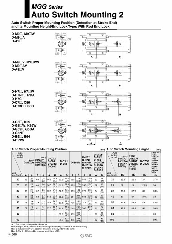
≈Hs
≈Hs
BA
≈Hs
A
A
B
B
≈Hs
BA
MGG Series
Auto Switch Mounting 2
∗( ): Set values for long stroke, double rodNote 1) Adjust the auto switch after confirming the operating conditions in the actual setting.Note 2) Values when “-C” is specified at the end of the cylinder model numberNote 3) The D-H7C cannot be mounted on ø80 and ø100.
Auto Switch Proper Mounting Position (Detection at Stroke End)and Its Mounting Height/End Lock Type: With Rod End Lock
D-M9, M9WD-M9AD-A9
D-M9V, M9WVD-M9AVD-A9V
D-G5, K59D-G5W, K59WD-G59F, G5BAD-G5NTD-B5, B64D-B59W
D-H7, H7WD-H7NF, H7BAD-H7CD-C7, C80D-C73C, C80C
Auto Switch Proper Mounting Position
Boresize (mm)
Autoswitchmodel
20
25
32
40
50
63
80
100
D-M9(V)D-M9W(V)D-M9A(V)
A
60
60
62
68
79
81
—
—
B24
(32)
24(32)
25(33)
27(36)
32(44)
32(44)
—
—
D-A9(V)
A
56
56
58
64
75
77
—
—
B20
(28)
20(28)
21(29)
23(32)
28(40)
28(40)
—
—
(mm)
20.5(28.5)
20.5(28.5)
21.5(29.5)
23.5(32.5)
28.5(40.5)
B14.5(22.5)
14.5(22.5)
15.5(23.5)
17.5(26.5)
22.5(34.5)
B17.5(25.5)
17.5(25.5)
18.5(26.5)
20.5(29.5)
25.5(37.5)
B19.5(27.5)
19.5(27.5)
20.5(28.5)
22.5(31.5)
27.5(39.5)
B16
(24)
16(24)
17(25)
19(28)
24(36)
28.5(40.5)
—
—
22.5(34.5)
30.5(44.5)
30.5(44.5)
25.5(37.5)
33.5(47.5)
33.5(47.5)
27.5(39.5)
—
—
24(36)
32(46)
32(46)
B
56.5
56.5
58.5
64.5
75.5
77.5
—
—
A
50.5
50.5
52.5
58.5
69.5
71.5
90.5
95.5
A
53.5
53.5
55.5
61
72.5
74.5
93.5
98.5
A
55.5
55.5
57.5
63.5
74.5
76.5
—
—
A
52
52
54
60
71
73
92
97
A
D-C7D-C80D-C73CD-C80C
D-B5D-B64 D-B59W
D-H7D-H7CD-H7NFD-H7WD-H7BA
D-G59FD-G5D-K59D-G5WD-K59WD-G5NTD-G5BA
Hs
26.5
29
32.5
37
42.5
49.5
—
—
Hs
26.5
29
32.5
37
42.5
49.5
—
—
Auto Switch Mounting Height
Boresize (mm)
Autoswitchmodel
20
25
32
40
50
63
80
100
(mm)
27
29.5
33
37.5
43
50
—
—
Hs Hs
27.5
30
33.5
38
43.5
50.5
59
69.5
D-C73CD-C80C
D-H7D-H7WD-H7NFD-H7BAD-C7D-C80
D-H7C Note 3)
D-G5D-G5WD-K59D-K59WD-G59FD-G5BAD-G5NTD-B5D-B59WD-B64
Note 2)
Note 2) D-M9(V)D-M9W(V)D-M9A(V)D-A9(V)
Note 2)
568A
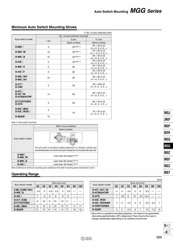
20 4.5
7
8
8
13
25
5
6
10
10
13
32
4.5
8
9
9
14
40
5.5
8
10
10
14
50
5
8
10
10
14
63
5.5
9
11
11
17
80
—
—
—
11
16
100
—
—
—
11
18
D-M9(V)/M9W(V)D-M9AD-A9D-C7/C80D-C73C/C80CD-B5/B64D-B59W
Auto switch modelBore size (mm)
Auto switch modelBore size (mm)
20
4
7
4
5
25
4
8.5
4
5
32
4.5
9
4.5
5.5
40
5
10
5
6
50
6
9.5
6
7
63
6.5
10.5
6.5
7.5
80
—
—
6.5
7.5
100
—
—
7
8
(mm)
D-H7/H7WD-H7BA/H7NFD-H7CD-G5/K59D-G5W/K59WD-G5NT/G5BAD-G59F
D-H7D-H7WD-H7BA/H7NF
D-C7D-C80
D-B5/B64D-G5/K59
D-B59W
5 50
10 60
5 65
5
10
75
Auto switch model1 pc.
2 pcs. “n” pcs.
No. of auto switches mounted
Same surface Same surface
n: No. of auto switches (mm)
D-C73C/C80CD-H7C
D-M9
D-M9W
D-M9A
D-A9
D-M9V
D-A9V
5
10
10
5
5
5
10
35
25
35
40 Note 1)
40 Note 1)
40 Note 1)
30 Note 1)
55 + 35 (n-2)(n = 2, 3, 4, 5…)
55 + 35 (n-2)(n = 2, 3, 4, 5…)
60 + 35 (n-2)(n = 2, 3, 4, 5…)
50 + 35 (n-2)(n = 2, 3, 4, 5…)
35 + 35 (n-2)(n = 2, 3, 4, 5…)
25 + 35 (n-2)(n = 2, 3, 4, 5…)
35 + 35 (n-2)(n = 2, 3, 4, 5…)
50 + 45(n-2)(n = 2, 3, 4, 5…)
60 + 45 (n-2)(n = 2, 3, 4, 5…)
65 + 50 (n-2)(n = 2, 3, 4, 5…)
75 + 55 (n-2)(n = 2, 3, 4, 5…)
D-M9WVD-M9AV
Note 2) Minimum stroke for mounting auto switches in the other mounting types mentioned in note 1.
Note 1) Auto switch mounting
D-M9AD-A9
Less than 60 stroke Note 2)
Less than 50 stroke Note 2)
D-M9D-M9W
Auto switch model
With 2 auto switches
Same surface
Less than 55 stroke Note 2)
The auto switch is mounted by slightly displacing it in a direction (cylinder tube circumferential exterior) so that the auto switch and lead wire do not interfere with each other.
Minimum Auto Switch Mounting Stroke
Auto Switch Mounting MGG Series
Operating Range
∗ Since this is a guideline including hysteresis, not meant to be guaranteed. (Assuming approximately ±30% dispersion) There may be the case to change substantially depending on an ambient environment.
569
MGJ
JMGP
MGP
MGPW
MGQ
MGG
MGC
MGF
MGZ
MGT
D-
-X
MGG
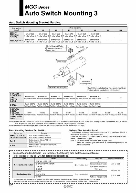
Switch bracket (Resin)Transparent (Nylon) Note 1)
White (PBT)
a
e
Auto switch
Switch holderb
Auto switchmounting screw
d
Auto switch mounting bandc
Auto Switch Mounting Bracket: Part No.
MGG Series
Auto Switch Mounting 3
Note 1) Since the switch bracket (made from nylon) are affected in an environment where alcohol, chloroform, methylamines, hydrochloric acid or sulfuric acid is splashed over, so it cannot be used. Please contact SMC regarding other chemicals.
Note 2) For the D-M9A (V) type auto switch, do not install the switch bracket on the indicator light.
[Stainless Steel Mounting Screw]The following stainless steel mounting screw kit is available. Use it in accordance with the operating environment.(Since the auto switch mounting bracket is not included, order it separately.)BBA3: D-B5/B6/G5/K5 typesNote 3) For details about the BBA3, refer to page 1225.
When the D-G5BA type auto switch is shipped independently, the BBA3 is attached.
Auto switchmodel
Bore size (mm)
20 25 32 40 50 63 80 100D-M9m(V)D-M9mW(V)D-A9m(V)
BMA3-020(A set of a, b, c, d)
BMA3-025(A set of a, b, c, d)
BMA3-032(A set of a, b, c, d)
BMA3-040(A set of a, b, c, d)
BMA3-050(A set of a, b, c, d)
BMA3-063(A set of a, b, c, d)
— —
D-M9mA(V) Note 2) BMA3-020S(A set of b, c, d, e)
BMA3-025S(A set of b, c, d, e)
BMA3-032S(A set of b, c, d, e)
BMA3-040S(A set of b, c, d, e)
BMA3-050S(A set of b, c, d, e)
BMA3-063S(A set of b, c, d, e)
— —
D-C7m/C80D-C73C/C80CD-H7mD-H7mWD-H7NF
BMA2-020A(A set of band and screw)
BMA2-025A(A set of band and screw)
BMA2-032A(A set of band and screw)
BMA2-040A(A set of band and screw)
BMA2-050A(A set of band and screw)
BMA2-063A(A set of band and screw)
— —
D-H7BA BMA2-020AS(A set of band and screw)
BMA2-025AS(A set of band and screw)
BMA2-032AS(A set of band and screw)
BMA2-040AS(A set of band and screw)
BMA2-050AS(A set of band and screw)
BMA2-063AS(A set of band and screw)
— —
D-B5m/B64D-B59WD-G5m/K59D-G5mW/K59WD-G5BA/G59FD-G5NT
BA-01(A set of band and screw)
BA-02(A set of band and screw)
BA-32(A set of band and screw)
BA-04(A set of band and screw)
BA-05(A set of band and screw)
BA-06(A set of band and screw)
BA-08(A set of band and screw)
BA-10(A set of band and screw)
∗ Band (c) is mounted so that the projected part is on the internal side (contact side with the tube).
Band Mounting Brackets Set Part No.Set part no. Contents
BMA2-mmmA (S)∗ S: Stainless steel screw
· Auto switch mounting band (c)· Auto switch mounting screw (d)
BJ4-1 · Switch bracket (White/PBT) (e)· Switch holder (b)
BJ5-1 · Switch bracket (Transparent/Nylon) (a)· Switch holder (b)
∗ For solid state auto switches, auto switches with a pre-wired connector are also available. Refer to pages 1192 and 1193 for details.∗ Normally closed (NC = b contact) solid state auto switches (D-F9G/F9H types) are also available. Refer to page 1137 for details.
Type Model FeaturesElectrical entry
D-H7A1, H7A2, H7B
D-H7NW, H7PW, H7BW
D-H7BA
D-G5NT
D-B53
D-C73, C76
D-C80
—
Diagnostic indication (2-color indicator)
Water resistant (2-color indicator)
With timer
—
Without indicator light
ø20 to ø63
ø20 to ø100
ø20 to ø63
Applicable bore size
Grommet (In-line)
Grommet (In-line)
Besides the models listed in How to Order, the following auto switches are applicable.Refer to pages 1119 to 1245 for detailed specifications.
Reed auto switch
Solid state auto switch
570
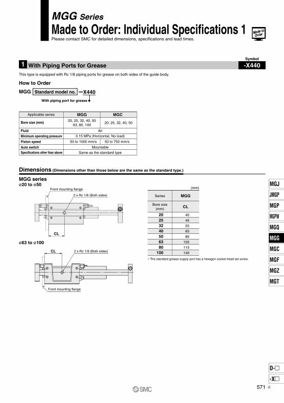
CL
2 x Rc 1/8 (Both sides)
Front mounting flange
MGG seriesø20 to ø50
ø63 to ø100
CL
MGG Series
Made to Order: Individual Specifications 1Please contact SMC for detailed dimensions, specifications and lead times.
Symbol
-X440With Piping Ports for Grease1
MGG MGC20, 25, 32, 40, 50
63, 80, 10020, 25, 32, 40, 50
This type is equipped with Rc 1/8 piping ports for grease on both sides of the guide body.
How to Order
MGG X440
With piping port for grease
Standard model no.
Dimensions (Dimensions other than those below are the same as the standard type.)
2 x Rc 1/8 (Both sides)
Front mounting flange
Applicable series
Bore size (mm)
Fluid
Minimum operating pressure
Piston speed
Auto switchSpecifications other than above
50 to 1000 mm/s 50 to 750 mm/s
Air
0.15 MPa (Horizontal, No load)
Mountable
Same as the standard type
Series MGG
CL
40
45
55
65
80
100
115
140
Bore size(mm)
20253240506380
100
(mm)
∗ The standard grease supply port has a hexagon socket head set screw.
571
MGJ
JMGP
MGP
MGPW
MGQ
MGG
MGC
MGF
MGZ
MGT
D-
-X
MGG
A
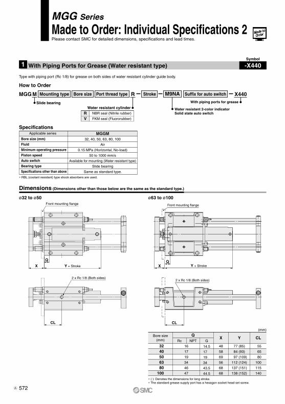
CL
X
Q
Y + Stroke
2 x Rc 1/8 (Both sides)
Front mounting flange
ø32 to ø50 ø63 to ø100
XQ
Y + Stroke
CL
Symbol
-X440With Piping Ports for Grease (Water resistant type)1
MGG Series
Made to Order: Individual Specifications 2Please contact SMC for detailed dimensions, specifications and lead times.
∗ RBL (coolant resistant) type shock absorbers are used.
SpecificationsMGGMApplicable series
Bore size (mm)
Fluid
Minimum operating pressure
Piston speed
Auto switch
Bearing type
Specifications other than above
32, 40, 50, 63, 80, 100
Air
0.15 MPa (Horizontal, No-load)
50 to 1000 mm/s
Available for mounting (Water resistant type)
Slide bearing
Same as standard type.
MGG Mounting type Bore size Port thread type Stroke
Water resistant 2-color indicatorSolid state auto switch
M
Slide bearing
R X440With piping ports for grease
Water resistant cylinderNBR seal (Nitrile rubber)
FKM seal (Fluororubber)
RV
Suffix for auto switch
Type with piping port (Rc 1/8) for grease on both sides of water resistant cylinder guide body.
How to Order
Dimensions (Dimensions other than those below are the same as the standard type.)
Front mounting flange
2 x Rc 1/8 (Both sides)
(mm)
∗ ( ): Denotes the dimensions for long stroke.∗ The standard grease supply port has a hexagon socket head set screw.
Bore size(mm)
Q
3240506380
100
16
17
19
34
46
47
X
48
58
69
56
68
68
Y
77 (85)
84 (93)
97 (109)
112 (124)
137 (151)
138 (152)
CL
55
65
80
100
115
140
M9NA
14.5
17
19
34
43.5
44.5
Rc NPT G
572A
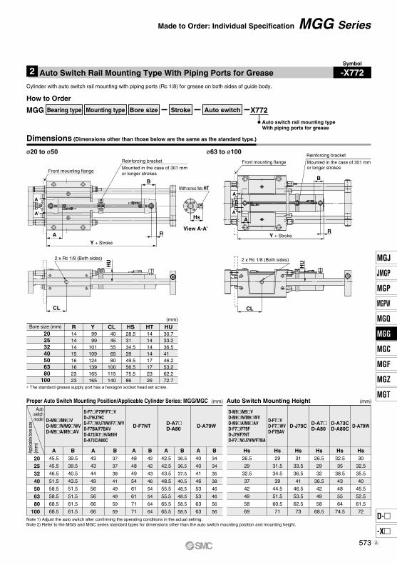
B
A
Hs
HU
R
CL
Y + Stroke
A'
A
Width across flats HT
Reinforcing bracket
Mounted in the case of 301 mm or longer strokes
2 x Rc 1/8 (Both sides)
Front mounting flange
View A-A'
Symbol
-X772Auto Switch Rail Mounting Type With Piping Ports for Grease2
Made to Order: Individual Specification MGG Series
∗ The standard grease supply port has a hexagon socket head set screw.
Bore size (mm) R20253240506380
100
1414141516162323
Y 99 99101109124139165165
CL 40 45 55 65 80100115140
HT1414141417172326
HS28.531 34.539 49.556.575.586
HU30.733.236.541 46.253.262.272.7
ø20 to ø50 ø63 to ø100
MGG X772
Front mounting flange
How to Order
Auto switch rail mounting typeWith piping ports for grease
Dimensions (Dimensions other than those below are the same as the standard type.)
Mounting typeBearing type Bore size Auto switchStroke
(mm)
HU
CL
B
RY + Stroke
AA'
A
Note 1) Adjust the auto switch after confirming the operating conditions in the actual setting.Note 2) Refer to the MGG and MGC series standard types for dimensions other than the auto switch mounting position and mounting height.
20253240506380
100
A B
Proper Auto Switch Mounting Position/Applicable Cylinder Series: MGG/MGC (mm)
D-F7/F79F/F7VD-J79/J79CD-F7W/J79W/F7WVD-F7BA/F7BAVD-A72/A7H/A80HD-A73C/A80C
D-M9/M9VD-M9W/M9WVD-M9A/M9AV
Autoswitchmodel
A B
Auto Switch Mounting Height (mm)
Hs30
32.5
35.5
40
45.5
52.5
61.5
72
32.5
35
38.5
43
48
55
64
74.5
D-A79W
Hs
D-A73CD-A80C
26.5
29
32
36.5
42
49
58
68.5
Hs
D-A7D-A80
31
33.5
36.5
41
46.5
53.5
62.5
73
Hs
D-J79C
29
31.5
34.5
39
44.5
51.5
60.5
71
Hs
D-F7VD-F7WVD-F7BAV
26.5
29
32.5
37
42
49
58
69
Hs
D-M9/M9VD-M9W/M9WVD-M9A/M9AVD-F7/F79FD-J79/F7NTD-F7W/J79W/F7BA
D-F7NT D-A7D-A80 D-A79W
45.5
45.5
46.5
51.5
58.5
58.5
68.5
68.5
39.5
39.5
40.5
43.5
51.5
51.5
61.5
61.5
A B43
43
44
49
56
56
66
66
37
37
38
41
49
49
59
59
48
48
49
54
61
61
71
71
42
42
43
46
54
54
64
64
A B42.5
42.5
43.5
48.5
55.5
55.5
65.5
65.5
36.5
36.5
37.5
40.5
48.5
48.5
58.5
58.5
A B40
40
41
46
53
53
63
63
34
34
35
38
46
46
56
56
Cylinder with auto switch rail mounting with piping ports (Rc 1/8) for grease on both sides of guide body.
Appli
cable
bor
e siz
e(m
m)
Reinforcing bracket
Mounted in the case of 301 mm or longer strokes
2 x Rc 1/8 (Both sides)
573
MGJ
JMGP
MGP
MGPW
MGQ
MGG
MGC
MGF
MGZ
MGT
D-
-X
MGG
A
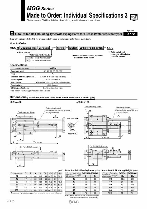
A'
A
B
RY + Stroke
A
X
QH
U
CL
Symbol
-X772Auto Switch Rail Mounting Type/With Piping Ports for Grease (Water resistant type)2
MGG Series
Made to Order: Individual Specifications 3Please contact SMC for detailed dimensions, specifications and lead times.
ø32 to ø50 ø63 to ø100
SpecificationsMGGMApplicable series
Bore size (mm)
Fluid
Minimum operating pressure
Piston speed
Auto switch
Bearing type
Other specifications
32, 40, 50, 63, 80, 100
Air
0.15 MPa (Horizontal, No-load)
50 to 1000 mm/s
Available for mounting (Water resistant type)
Slide bearing
Same as standard type.
MGG Stroke
Water resistant 2-color indicatorSolid state auto switch
M
Slide bearing
R X772Auto switch rail mounting with piping ports for grease
Water resistant cylinder
NBR seals (Nitrile rubber)
FKM seals (Fluororubber)
RV
∗ The standard grease supply port has a hexagon socket head set screw.
Note ) Adjust the auto switch after confirming the operating conditions in the actual setting.
Bore size (mm) HU3240506380
100
36.5
41
46.2
53.2
62.2
72.2
HT14
14
17
17
23
26
HS34.5
39
49.5
56.5
75.5
86
CL 55
65
80
100
115
140
Y105
113
129
144
171
172
X48
58
69
56
68
68
R14
15
16
16
23
23
Q16
17
19
34
46
47
Suffix for auto switch
D-F7BAL/F7BAVLB38
41
49
49
59
59
A50
55
63
63
74
75
3240506380
100
Auto switchmodelApplicable
bore size (mm)
D-F7BALHs32.5
37
42
49
58
69
D-F7BAVLHs34.5
39
44.5
51.5
60.5
71
3240506380
100
Auto Switch Mounting HeightProper Auto Switch Mounting Position
Front mounting flange
Type with piping port (Rc 1/8) for grease on both sides of water resistant cylinder guide body.
How to Order
∗ RBL (coolant resistant) type shock absorbers are used.
Dimensions (Dimensions other than those below are the same as the standard type.)
Reinforcing bracket
Mounted in the case of 301 mm or longer strokes
2 x Rc 1/8 (Both sides)
Mounting type Bore size
Auto switchmodelApplicable
bore size (mm)
(mm)(mm) (mm)
A
B
Hs
HU
R
CL
X
Q
Y + Stroke
A'
A
Reinforcing bracket
Mounted in the case of 301 mm or longer strokes
2 x Rc 1/8 (Both sides)
Front mounting flange
View A-A'
Width across flats HT
M9NA
574A

Guide body
Hexagon sockethead cap screw
Rear plate
Protective cover
Cover mounting bolt
Protective cover
Cover mounting boltMovement
Close
Mounting and Adjustment
Warning Caution
Handling on Shock Absorber
1. Install a protective cover.Since the rear plate moves back and forth during mounting, handling and operation, be careful that hands, etc., do not get caught between the cylinder and the rear plate.When you are going to fit this product to the outside of your equipment, take preventative measures such as installing a protective cover.
Protective cover installation example
Caution1. Be sure to confirm by referring to the shock absorber (RB series,
Best Pneumatics No. 2-3) for details.
1. Use caution that no scratch or dent will be given to the slide part of the guide rod. Because the outer circumference of the guide rod is manufactured with precise tolerances, even a slight deformation, scratch, or gouge can lead to faulty operation or reduced durability.
2. When mounting the guide body, use a mounting surface having a high degree of flatness.If twisting or bending occurs in the guide rods, this can cause problems such as a large increase in operating resistance and reduced performance due to premature wear of the bearings.
3. Mount in locations where maintenance will be easy.Ensure enough clearance around the cylinder to allow for unobstructed maintenance and inspection work.
4. Extension stroke adjustmentTo adjust the extension stroke by moving the rear plate, loosen the hexagon socket head screws on the left and right sides of the plate, move the rear plate to the desired stroke position in proximity to the guide body, and retighten the hexagon socket head screws on the left and right.
5. Lubrication of bearingsLubricate from the grease nipple so that there is no contamination from foreign matter.In addition, use good quality no. 2 lithium soap base grease.
6. Mounting orientationIf the guide body is mounted so that it is inclined more than 90°, the rear plate may interfere with the basic cylinder head end due to the deflection of guide rods. Please consult with SMC.
7. Fixing of base cylinderWhen the product is mounted and operated in a location with low rigidity, bending moment may be applied to the base cylinder by vibrations generated at the stroke end, causing damage to the cylinder. In such cases, install a support bracket to suppress the vibration of the body of the base cylinder or reduce the piston speed until the body does not vibrate at the stroke end.
MGG SeriesSpecific Product Precautions 1Be sure to read this before handling the products.Refer to back page 50 for Safety Instructions and pages 3 to 12 for Actuator and Auto Switch Precautions.
575
MGJ
JMGP
MGP
MGPW
MGQ
MGG
MGC
MGF
MGZ
MGT
D-
-X
MGG
A

Head end lock Rod end lock
Locked condition Released condition
W
W
Use the Recommended Pneumatic Circuit
Caution
Operating Precautions
Caution
Operating Pressure
Caution
Exhaust Speed
Caution
Releasing the Lock
Warning
Bore size(mm)
20, 25, 3240, 50, 6380, 100
Thread size
M2.5 x 0.45 x 25 L or more
M3 x 0.5 x 30 L or more
M5 x 0.8 x 40 L or more
Pulling force(N)
4.9
10
24.5
Stroke(mm)
2
3
3
Manual Release
Caution
Warning
With End Lock
This is necessary for proper operation and release of the lock.
Rubbercap
LockRelease
1. Do not use 3 position solenoid valves.Avoid use in combination with 3 position solenoid valves (especially closed center metal seal types). If pressure is trapped in the port on the lock mechanism side, the cylinder cannot be locked. Furthermore, even after being locked, the lock may be released after some time, due to air leaking from the solenoid valve and entering the cylinder.
2. Back pressure is required when releasing the lock.Before starting operation, be sure to control the system so that air is supplied to the side without the lock mechanism as shown in the figure above. There is a possibility that the lock may not be released. ( Refer to the section (right side) on releasing the lock.)
3. Release the lock when mounting or adjusting the cylinder.If mounting or other work is performed when the cylinder is locked, the lock unit may be damaged.
4. Operate with a load ratio of 50% or less.If the load ratio exceeds 50%, this may cause problems such as failure of the lock to release, or damage to the lock unit.
5. Do not operate multiple cylinders in synchronization. Avoid applications in which two or more end lock cylinders are synchronized to move one workpiece, as one of the cylinder locks may not be able to release when required.
6. Use a speed controller with meter-out control.Lock cannot be released occasionally by meter-in control.
7. Be sure to operate completely to the cylinder stroke end on the side with the lock.If the cylinder piston does not reach the end of the stroke, locking and unlocking may not be possible. Therefore, do not adjust the stroke with the adjustment bolts or shock absorbers.
8. Do not use an air cylinder as an air-hydro cylinder. This will cause leakage of hydraulic fluid.
9. Adjust an auto switch's position so that it operates for movement to both the stroke end and backlash (2 mm) positions. When a 2-color indicator switch is adjusted for green indication at the stroke end, it may change to red for the backlash return, but this is not abnormal.
1. Operate within the specified cylinder speed.Otherwise, cylinder and seal damage may occur.
1. Use air pressure of at least 0.15 MPa for the port on the lock mechanism side. This is necessary to release the lock.
1. Locking will occur automatically if the pressure applied to the port on the lock mechanism side falls to 0.05 MPa or less. In cases where the piping on the lock mechanism side is long and thin, or the speed controller is separated at some distance from the cylinder port, the exhaust speed will be reduced. Take note that some time may be required for the lock to engage. In addition, clogging of a silencer mounted on the solenoid valve exhaust port can produce the same effect.
1. Before releasing the lock, be sure to supply air to the side without the lock mechanism, so that there is no load applied to the lock mechanism when it is released. (Refer to the recommended pneumatic circuits.) If the lock is released when the port on the other side is in an exhaust state, and with a load applied to the lock unit, the lock unit may be subjected to an excessive force and be damaged. Furthermore, sudden movement of the piston rod is very dangerous.
1. Manual release (Non-lock type)Insert the accessory bolt from the top of the rubber cap (it is not necessary to remove the rubber cap), and after screwing it into the lock piston, pull it to release the lock. If you stop pulling the bolt, the lock will return to an operational state. Thread sizes, pulling forces and strokes are as shown below.
2. Manual release, Lock typeWhile pushing the M/O knob, turn it 90° counterclockwise. The lock is released (and remains in a released state) by aligning the mark on the cap with the OFF mark on the M/O knob.When locking is desired, turn M/O button clockwise 90° while pushing fully, correspond on cap and ON mark on M/O button. The correct position is confirmed by a click sound “click”. If not confirmed, locking is not done.
Remove the bolt for normal operation. It can cause lock malfunction or faulty release.
MGG SeriesSpecific Product Precautions 2Be sure to read this before handling the products.Refer to back page 50 for Safety Instructions and pages 3 to 12 for Actuator and Auto Switch Precautions.
576