Embed Size (px)
Citation preview
A member of the UNITED GRINDING Group
MÄGERLEGRINDING SYSTEMS
Key dataModular system for customized solutions
Maximum performance and productivity
Swiss-made precision
Special-purpose machinery with the reliability of standard equipment
Power and precision
Mägerle AG Maschinenfabrik
Precision, quality and flexibility are key attributes of the products manu-
factured by Mägerle AG Maschinenfabrik. A technology leader for high-
performance surface and profile grinding systems, the company founded in
1929 primarily specializes in customized solutions.
At the heart of the international success of our high-quality Swiss machin-
ery is the unique design principle of the MÄGERLE modular system. Thanks
to state-of-the-art technology, MÄGERLE can offer customers from many
branches of industry reliable grinding centers. The high machining preci-
sion of the custom special-purpose machines ensures that our customers
remain competitive.
Alongside decades of accumulated expertise, our highly motivated and
dedicated employees play a key role in the success of the company.
As part of the UNITED GRINDING Group, MÄGERLE is a strong member of
the group of globally leading machinery engineering companies for grind-
ing machines. All over the world, this gives MÄGERLE customers access to
an extensive network of experienced service and engineering technicians.
3MÄGERLE
GRINDING SYSTEMS
Established modular system · Hydrostatic guideways ·
Maximum grinding and cooling performance · Process
expertise for high process reliability · System integra-
tion expertise
MÄGERLE GRINDING SYSTEMS
4 MÄGERLE
GRINDING SYSTEMS
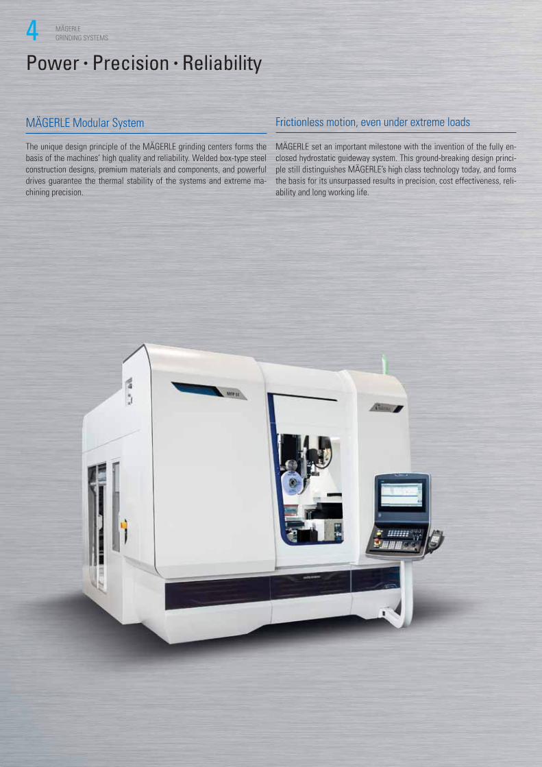
MÄGERLE Modular System
The unique design principle of the MÄGERLE grinding centers forms the
basis of the machines’ high quality and reliability. Welded box-type steel
construction designs, premium materials and components, and powerful
drives guarantee the thermal stability of the systems and extreme ma-
chining precision.
Frictionless motion, even under extreme loads
MÄGERLE set an important milestone with the invention of the fully en-
closed hydrostatic guideway system. This ground-breaking design princi-
ple still distinguishes MÄGERLE’s high class technology today, and forms
the basis for its unsurpassed results in precision, cost effectiveness, reli-
ability and long working life.
Power • Precision • Reliability
5MÄGERLE
GRINDING SYSTEMS
Demanding tasks
With their equally high removal capacity and machining precision,
MÄGERLE’s grinding centers are recognized on the market as top-class
machines. They demonstrate their performances and versatility daily in
demanding applications in the turbine industry, the automotive and air-
craft industry, the hydraulics industry and the energy sector, as well as
machine tools and toolmaking. All industries that make the highest de-
mands in respect of mechanical, ergonomic and operational qualities.
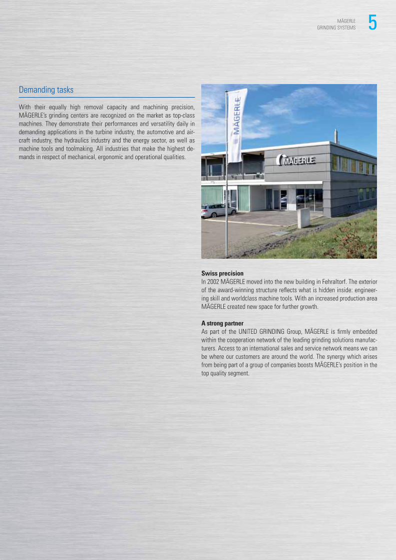
Swiss precisionIn 2002 MÄGERLE moved into the new building in Fehraltorf. The exterior
of the award-winning structure reflects what is hidden inside: engineer-
ing skill and worldclass machine tools. With an increased production area
MÄGERLE created new space for further growth.
A strong partnerAs part of the UNITED GRINDING Group, MÄGERLE is firmly embedded
within the cooperation network of the leading grinding solutions manufac-
turers. Access to an international sales and service network means we can
be where our customers are around the world. The synergy which arises
from being part of a group of companies boosts MÄGERLE’s position in the
top quality segment.
6 MÄGERLE
GRINDING SYSTEMS
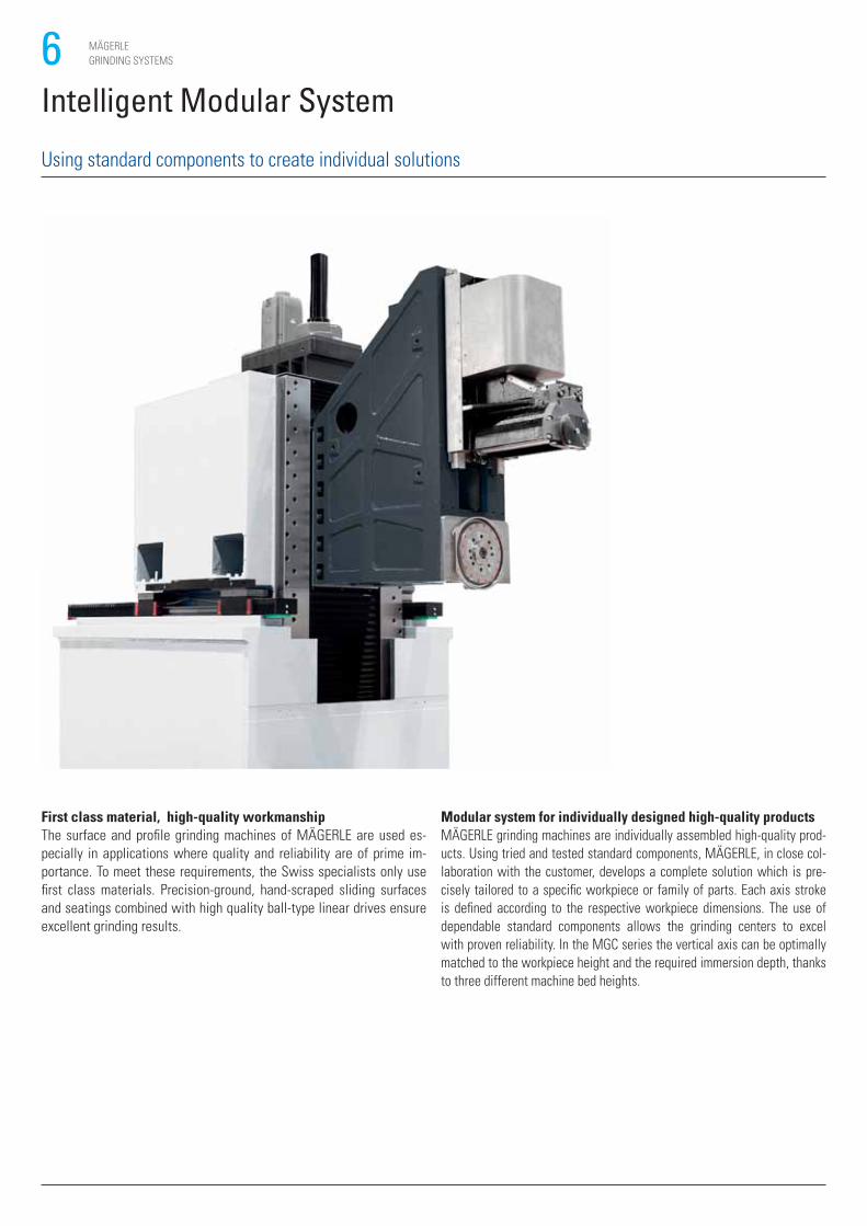
Modular system for individually designed high-quality productsMÄGERLE grinding machines are individually assembled high-quality prod-
ucts. Using tried and tested standard components, MÄGERLE, in close col-
laboration with the customer, develops a complete solution which is pre-
cisely tailored to a specific workpiece or family of parts. Each axis stroke
is defined according to the respective workpiece dimensions. The use of
dependable standard components allows the grinding centers to excel
with proven reliability. In the MGC series the vertical axis can be optimally
matched to the workpiece height and the required immersion depth, thanks
to three different machine bed heights.
First class material, high-quality workmanshipThe surface and profile grinding machines of MÄGERLE are used es-
pecially in applications where quality and reliability are of prime im-
portance. To meet these requirements, the Swiss specialists only use
first class materials. Precision-ground, hand-scraped sliding surfaces
and seatings combined with high quality ball-type linear drives ensure
excellent grinding results.
Intelligent Modular System
Using standard components to create individual solutions
7MÄGERLE
GRINDING SYSTEMS
ST
R
V
H
FT
■
■
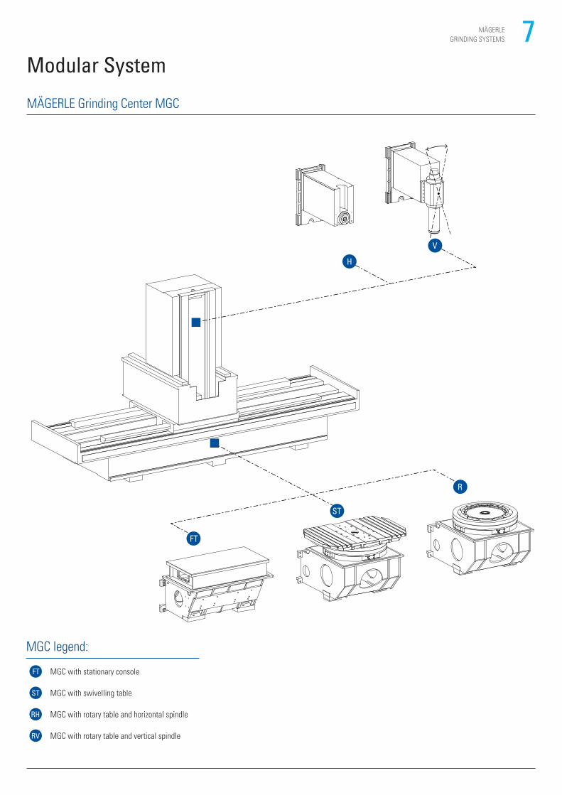
MÄGERLE Grinding Center MGC
Modular System
MGC legend:
FT MGC with stationary console
ST MGC with swivelling table
RH MGC with rotary table and horizontal spindle
RV MGC with rotary table and vertical spindle
8 MÄGERLE
GRINDING SYSTEMS
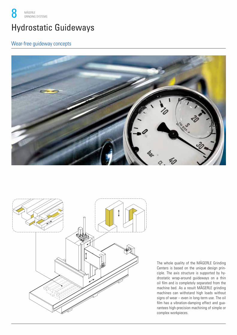
Hydrostatic Guideways
The whole quality of the MÄGERLE Grinding
Centers is based on the unique design prin-
ciple. The axis structure is supported by hy-
drostatic wrap-around guideways on a thin
oil film and is completely separated from the
machine bed. As a result MÄGERLE grinding
machines can withstand high loads without
signs of wear – even in long-term use. The oil
film has a vibration-damping effect and gua-
rantees high-precision machining of simple or
complex workpieces.
Wear-free guideway concepts
9MÄGERLE
GRINDING SYSTEMS
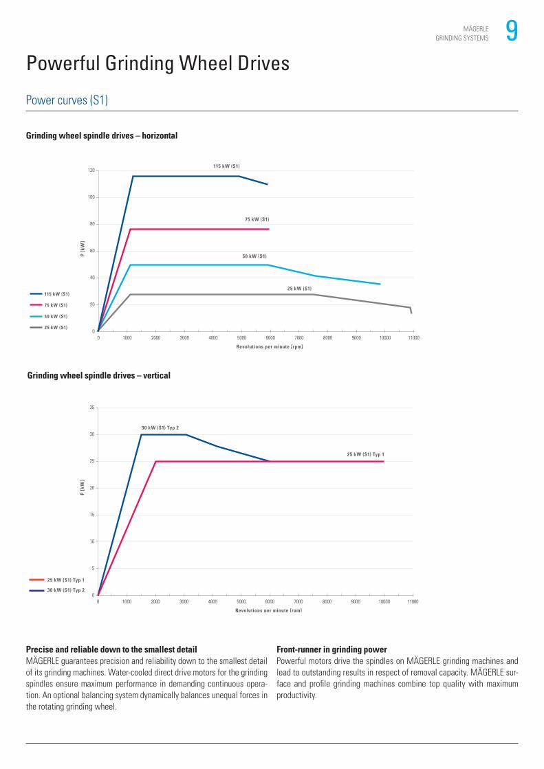
Powerful Grinding Wheel Drives
Precise and reliable down to the smallest detailMÄGERLE guarantees precision and reliability down to the smallest detail
of its grinding machines. Water-cooled direct drive motors for the grinding
spindles ensure maximum performance in demanding continuous opera-
tion. An optional balancing system dynamically balances unequal forces in
the rotating grinding wheel.
Front-runner in grinding powerPowerful motors drive the spindles on MÄGERLE grinding machines and
lead to outstanding results in respect of removal capacity. MÄGERLE sur-
face and profile grinding machines combine top quality with maximum
productivity.
Power curves (S1)
Grinding wheel spindle drives – vertical
35
30
25
20
15
10
5
010000 2000 3000 4000 5000 6000 7000 8000 9000 10000 11000
Revolutions per minute [rpm]
30 kW (S1) Typ 2
25 kW (S1) Typ 1
P [k
W]
25 kW (S1) Typ 1
30 kW (S1) Typ 2
Grinding wheel spindle drives – horizontal
2000 3000 4000 5000 6000 7000 8000 9000 10000 11000
120
100
80
60
40
20
010000
Revolutions per minute [rpm]
115 kW (S1)
75 kW (S1)
50 kW (S1)
25 kW (S1)
P [k
W]
115 kW (S1)
75 kW (S1)
50 kW (S1)
25 kW (S1)
10 MÄGERLE
GRINDING SYSTEMS
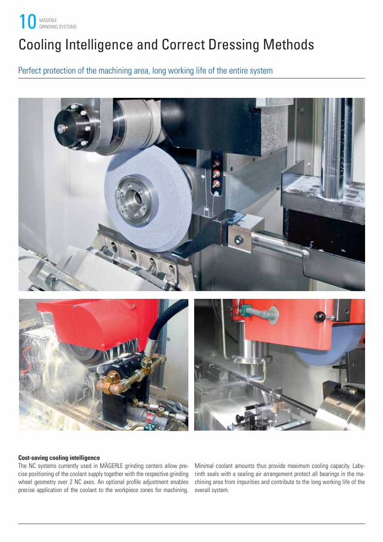
Cost-saving cooling intelligenceThe NC systems currently used in MÄGERLE grinding centers allow pre-
cise positioning of the coolant supply together with the respective grinding
wheel geometry over 2 NC axes. An optional profile adjustment enables
precise application of the coolant to the workpiece zones for machining.
Cooling Intelligence and Correct Dressing Methods
Perfect protection of the machining area, long working life of the entire system
Minimal coolant amounts thus provide maximum cooling capacity. Laby-
rinth seals with a sealing air arrangement protect all bearings in the ma-
chining area from impurities and contribute to the long working life of the
overall system.
11MÄGERLE
GRINDING SYSTEMS
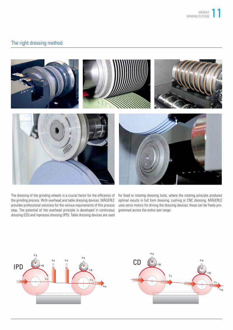
The dressing of the grinding wheels is a crucial factor for the efficiency of
the grinding process. With overhead and table dressing devices, MÄGERLE
provides professional solutions for the various requirements of this process
step. The potential of the overhead principle is developed in continuous
dressing (CD) and inprocess dressing (IPD). Table dressing devices are used
for fixed or rotating dressing tools, where the rotating principle produces
optimal results in full form dressing, cushing or CNC dressing. MÄGERLE
uses servo motors for driving the dressing devices; these can be freely pro-
grammed across the entire rpm range.
The right dressing method
v Rv R
a da d
vw
a da d
v c v c
IPD v R
v c
v c
v R
a d
a d
v w
CD
12 MÄGERLE
GRINDING SYSTEMS
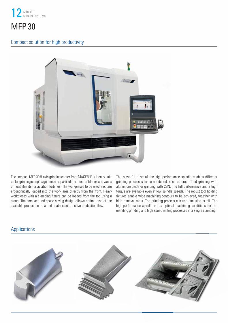
MFP 30
Compact solution for high productivity
Applications
The compact MFP 30 5-axis grinding center from MÄGERLE is ideally suit-
ed for grinding complex geometries, particularly those of blades and vanes
or heat shields for aviation turbines. The workpieces to be machined are
ergonomically loaded into the work area directly from the front. Heavy
workpieces with a clamping fixture can be loaded from the top using a
crane. The compact and space-saving design allows optimal use of the
available production area and enables an effective production flow.
The powerful drive of the high-performance spindle enables different
grinding processes to be combined, such as creep feed grinding with
aluminium oxide or grinding with CBN. The full performance and a high
torque are available even at low spindle speeds. The robust tool holding
fixtures enable wide machining contours to be achieved, together with
high removal rates. The grinding process can use emulsion or oil. The
high-performance spindle offers optimal machining conditions for de-
manding grinding and high speed milling processes in a single clamping.
13MÄGERLE
GRINDING SYSTEMS
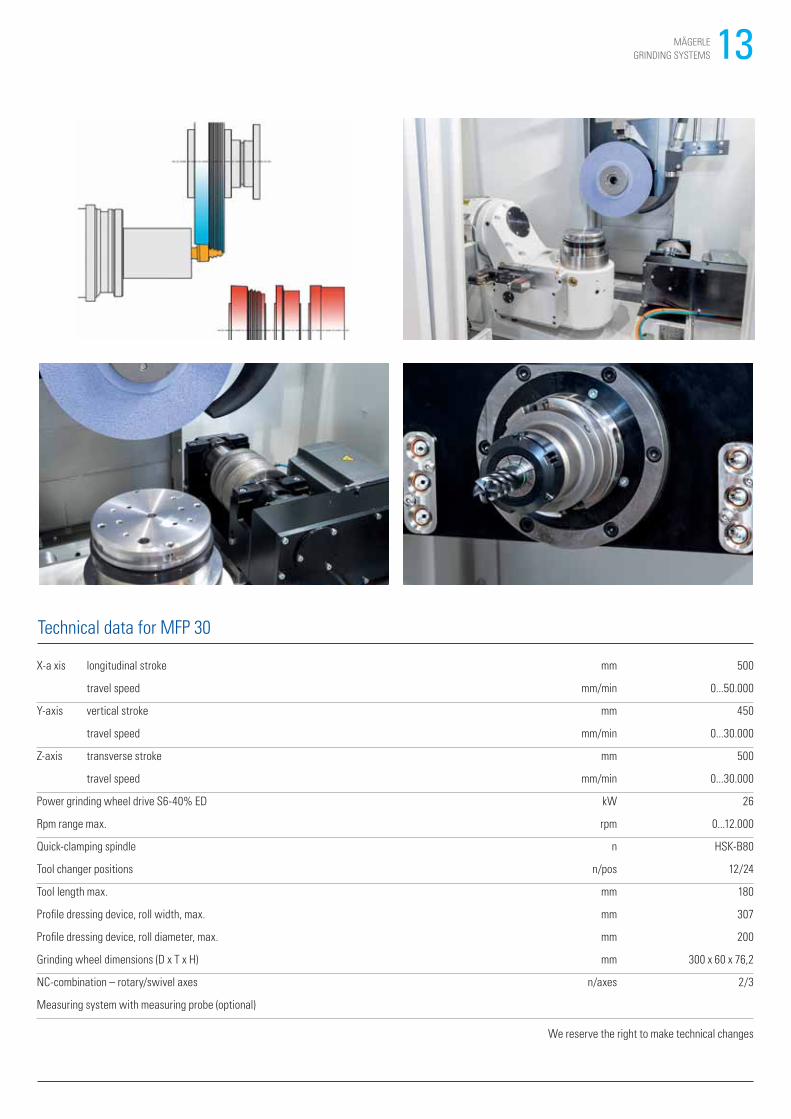
Technical data for MFP 30
X-a xis longitudinal stroke mm 500
travel speed mm/min 0...50.000
Y-axis vertical stroke mm 450
travel speed mm/min 0...30.000
Z-axis transverse stroke mm 500
travel speed mm/min 0...30.000
Power grinding wheel drive S6-40% ED kW 26
Rpm range max. rpm 0...12.000
Quick-clamping spindle n HSK-B80
Tool changer positions n/pos 12/24
Tool length max. mm 180
Profile dressing device, roll width, max. mm 307
Profile dressing device, roll diameter, max. mm 200
Grinding wheel dimensions (D x T x H) mm 300 x 60 x 76,2
NC-combination – rotary/swivel axes n/axes 2/3
Measuring system with measuring probe (optional)
We reserve the right to make technical changes
14 MÄGERLE
GRINDING SYSTEMS
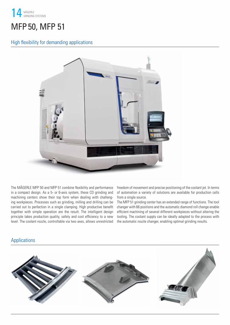
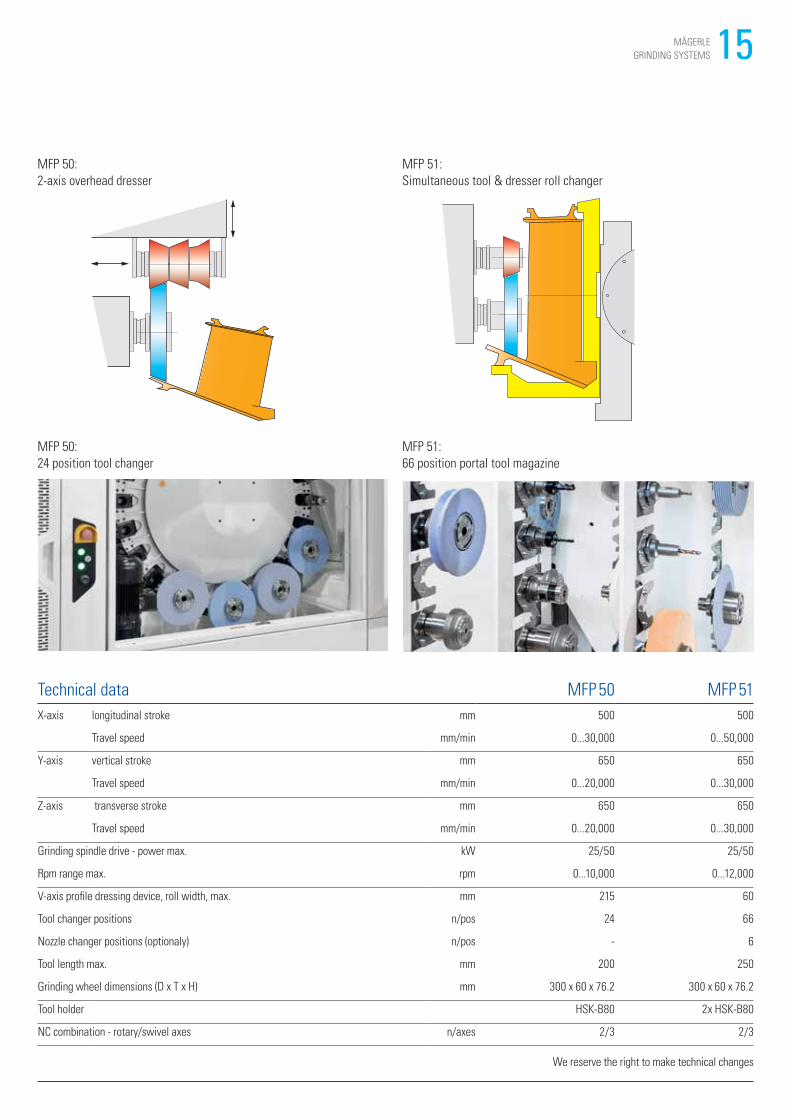
The MÄGERLE MFP 50 and MFP 51 combine flexibility and performance
in a compact design. As a 5- or 6-axis system, these CD grinding and
machining centers show their top form when dealing with challeng-
ing workpieces. Processes such as grinding, milling and drilling can be
carried out to perfection in a single clamping. High productive benefit
together with simple operation are the result. The intelligent design
principle takes production quality, safety and cost efficiency to a new
level. The coolant nozzle, controllable via two axes, allows unrestricted
MFP 50, MFP 51
High flexibility for demanding applications
Applications
freedom of movement and precise positioning of the coolant jet. In terms
of automation a variety of solutions are available for production cells
from a single source.
The MFP 51 grinding center has an extended range of functions. The tool
changer with 66 positions and the automatic diamond roll change enable
efficient machining of several different workpieces without altering the
tooling. The coolant supply can be ideally adapted to the process with
the automatic nozzle changer, enabling optimal grinding results.
15MÄGERLE
GRINDING SYSTEMS
MFP 50:
24 position tool changer
MFP 51:
66 position portal tool magazine
MFP 50:
2-axis overhead dresser
Technical data MFP 50 MFP 51
X-axis longitudinal stroke mm 500 500
Travel speed mm/min 0...30,000 0...50,000
Y-axis vertical stroke mm 650 650
Travel speed mm/min 0...20,000 0...30,000
Z-axis transverse stroke mm 650 650
Travel speed mm/min 0...20,000 0...30,000
Grinding spindle drive - power max. kW 25/50 25/50
Rpm range max. rpm 0...10,000 0...12,000
V-axis profile dressing device, roll width, max. mm 215 60
Tool changer positions n/pos 24 66
Nozzle changer positions (optionaly) n/pos - 6
Tool length max. mm 200 250
Grinding wheel dimensions (D x T x H) mm 300 x 60 x 76.2 300 x 60 x 76.2
Tool holder HSK-B80 2x HSK-B80
NC combination - rotary/swivel axes n/axes 2/3 2/3
We reserve the right to make technical changes
MFP 51:
Simultaneous tool & dresser roll changer
16 MÄGERLE
GRINDING SYSTEMS
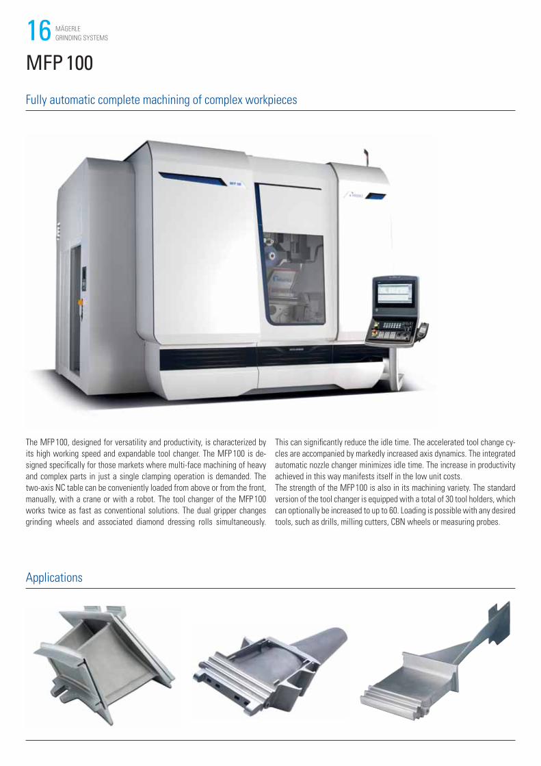
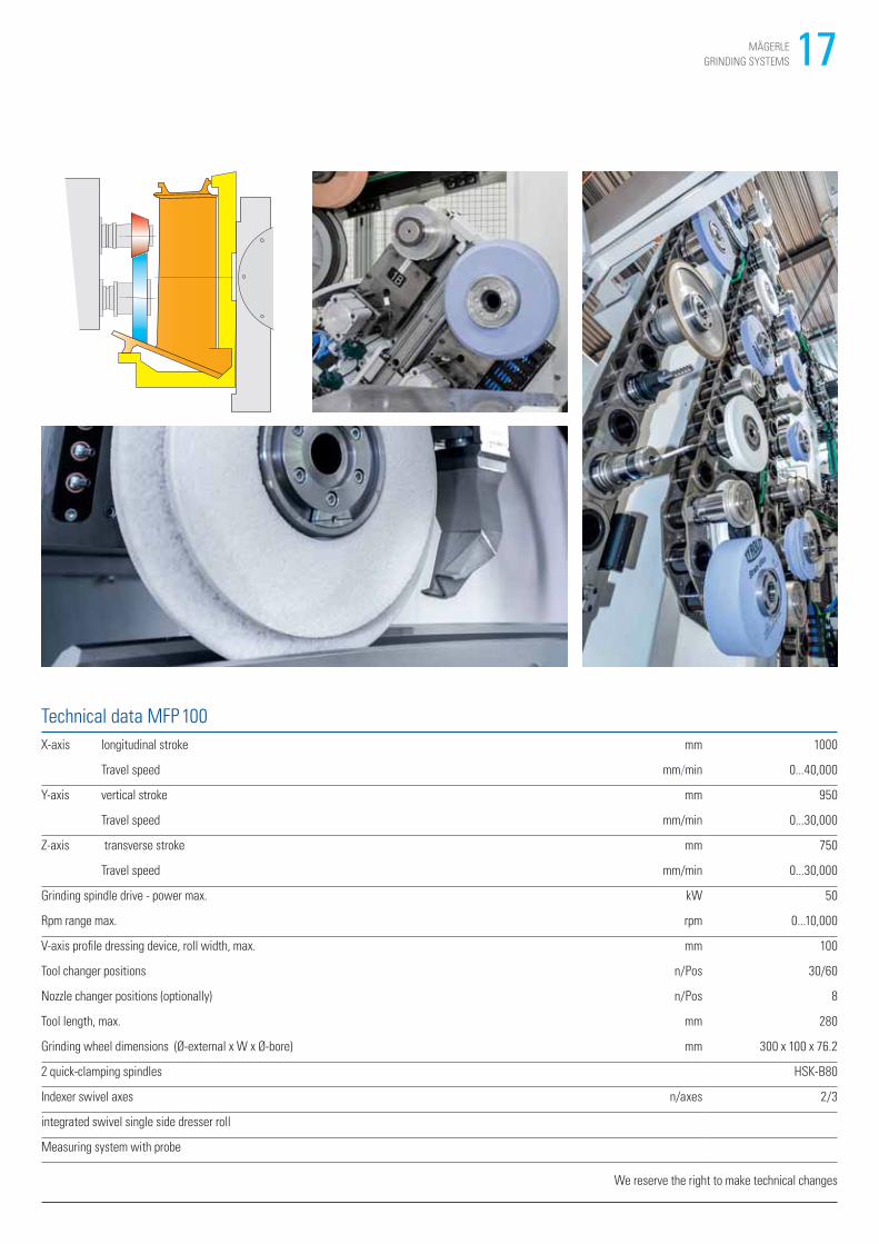
The MFP 100, designed for versatility and productivity, is characterized by
its high working speed and expandable tool changer. The MFP 100 is de-
signed specifically for those markets where multi-face machining of heavy
and complex parts in just a single clamping operation is demanded. The
two-axis NC table can be conveniently loaded from above or from the front,
manually, with a crane or with a robot. The tool changer of the MFP 100
works twice as fast as conventional solutions. The dual gripper changes
grinding wheels and associated diamond dressing rolls simultaneously.
This can significantly reduce the idle time. The accelerated tool change cy-
cles are accompanied by markedly increased axis dynamics. The integrated
automatic nozzle changer minimizes idle time. The increase in productivity
achieved in this way manifests itself in the low unit costs.
The strength of the MFP 100 is also in its machining variety. The standard
version of the tool changer is equipped with a total of 30 tool holders, which
can optionally be increased to up to 60. Loading is possible with any desired
tools, such as drills, milling cutters, CBN wheels or measuring probes.
MFP 100
Fully automatic complete machining of complex workpieces
Applications
17MÄGERLE
GRINDING SYSTEMS
Technical data MFP 100
X-axis longitudinal stroke mm 1000
Travel speed mm/min 0...40,000
Y-axis vertical stroke mm 950
Travel speed mm/min 0...30,000
Z-axis transverse stroke mm 750
Travel speed mm/min 0...30,000
Grinding spindle drive - power max. kW 50
Rpm range max. rpm 0...10,000
V-axis profile dressing device, roll width, max. mm 100
Tool changer positions n/Pos 30/60
Nozzle changer positions (optionally) n/Pos 8
Tool length, max. mm 280
Grinding wheel dimensions (Ø-external x W x Ø-bore) mm 300 x 100 x 76.2
2 quick-clamping spindles HSK-B80
Indexer swivel axes n/axes 2/3
integrated swivel single side dresser roll
Measuring system with probe
We reserve the right to make technical changes
18 MÄGERLE
GRINDING SYSTEMS
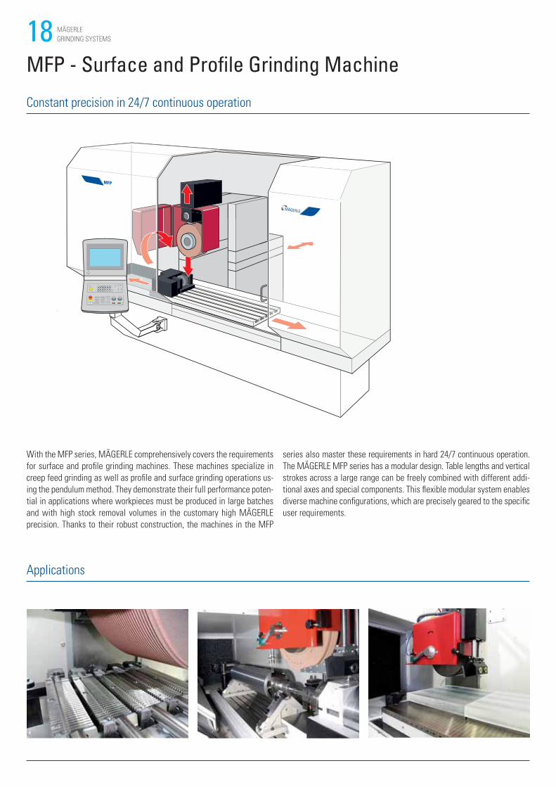
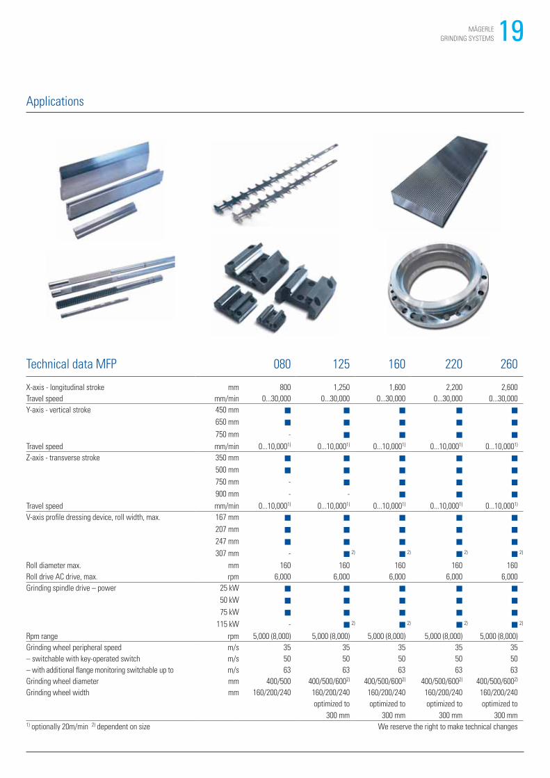
MFP - Surface and Profile Grinding Machine
With the MFP series, MÄGERLE comprehensively covers the requirements
for surface and profile grinding machines. These machines specialize in
creep feed grinding as well as profile and surface grinding operations us-
ing the pendulum method. They demonstrate their full performance poten-
tial in applications where workpieces must be produced in large batches
and with high stock removal volumes in the customary high MÄGERLE
precision. Thanks to their robust construction, the machines in the MFP
series also master these requirements in hard 24/7 continuous operation.
The MÄGERLE MFP series has a modular design. Table lengths and vertical
strokes across a large range can be freely combined with different addi-
tional axes and special components. This flexible modular system enables
diverse machine configurations, which are precisely geared to the specific
user requirements.
Constant precision in 24/7 continuous operation
Applications
19MÄGERLE
GRINDING SYSTEMS
Applications
Technical data MFP 080 125 160 220 260
X-axis - longitudinal stroke mm 800 1,250 1,600 2,200 2,600
Travel speed mm/min 0...30,000 0...30,000 0...30,000 0...30,000 0...30,000
Y-axis - vertical stroke 450 mm ■ ■ ■ ■ ■
650 mm ■ ■ ■ ■ ■
750 mm - ■ ■ ■ ■
Travel speed mm/min 0...10,0001) 0...10,0001) 0...10,0001) 0...10,0001) 0...10,0001)
Z-axis - transverse stroke 350 mm ■ ■ ■ ■ ■
500 mm ■ ■ ■ ■ ■
750 mm - ■ ■ ■ ■
900 mm - - ■ ■ ■
Travel speed mm/min 0...10,0001) 0...10,0001) 0...10,0001) 0...10,0001) 0...10,0001)
V-axis profile dressing device, roll width, max. 167 mm ■ ■ ■ ■ ■
207 mm ■ ■ ■ ■ ■
247 mm ■ ■ ■ ■ ■
307 mm - ■ 2) ■ 2) ■ 2) ■ 2)
Roll diameter max. mm 160 160 160 160 160
Roll drive AC drive, max. rpm 6,000 6,000 6,000 6,000 6,000
Grinding spindle drive – power 25 kW ■ ■ ■ ■ ■
50 kW ■ ■ ■ ■ ■
75 kW ■ ■ ■ ■ ■
115 kW - ■ 2) ■ 2) ■ 2) ■ 2)
Rpm range rpm 5,000 (8,000) 5,000 (8,000) 5,000 (8,000) 5,000 (8,000) 5,000 (8,000)
Grinding wheel peripheral speed m/s 35 35 35 35 35
– switchable with key-operated switch m/s 50 50 50 50 50
– with additional flange monitoring switchable up to m/s 63 63 63 63 63
Grinding wheel diameter mm 400/500 400/500/6002) 400/500/6002) 400/500/6002) 400/500/6002)
Grinding wheel width mm 160/200/240 160/200/240 160/200/240 160/200/240 160/200/240
optimized to
300 mm
optimized to
300 mm
optimized to
300 mm
optimized to
300 mm1) optionally 20m/min 2) dependent on size We reserve the right to make technical changes
20 MÄGERLE
GRINDING SYSTEMS
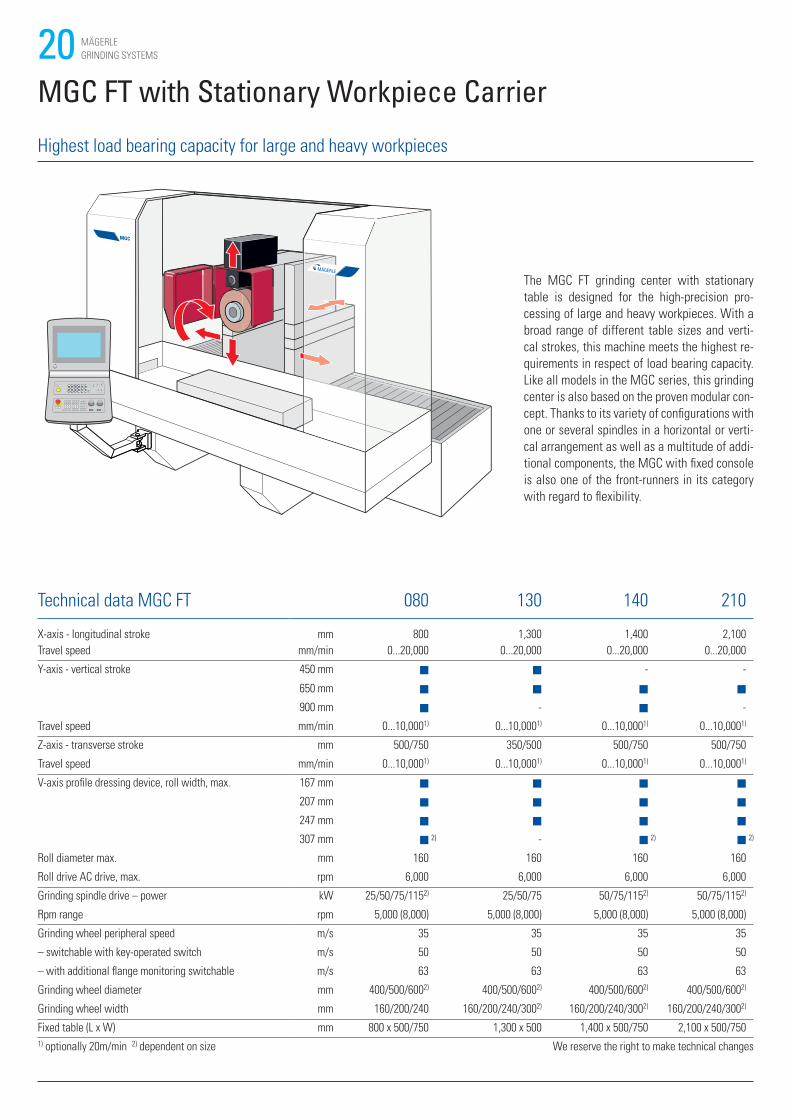
MGC FT with Stationary Workpiece Carrier
The MGC FT grinding center with stationary
table is designed for the high-precision pro-
cessing of large and heavy workpieces. With a
broad range of different table sizes and verti-
cal strokes, this machine meets the highest re-
quirements in respect of load bearing capacity.
Like all models in the MGC series, this grinding
center is also based on the proven modular con-
cept. Thanks to its variety of configurations with
one or several spindles in a horizontal or verti-
cal arrangement as well as a multitude of addi-
tional components, the MGC with fixed console
is also one of the front-runners in its category
with regard to flexibility.
Highest load bearing capacity for large and heavy workpieces
Technical data MGC FT 080 130 140 210
X-axis - longitudinal stroke mm 800 1,300 1,400 2,100
Travel speed mm/min 0...20,000 0...20,000 0...20,000 0...20,000
Y-axis - vertical stroke 450 mm ■ ■ - -
650 mm ■ ■ ■ ■
900 mm ■ - ■ -
Travel speed mm/min 0...10,0001) 0...10,0001) 0...10,0001) 0...10,0001)
Z-axis - transverse stroke mm 500/750 350/500 500/750 500/750
Travel speed mm/min 0...10,0001) 0...10,0001) 0...10,0001) 0...10,0001)
V-axis profile dressing device, roll width, max. 167 mm ■ ■ ■ ■
207 mm ■ ■ ■ ■
247 mm ■ ■ ■ ■
307 mm ■ 2) - ■ 2) ■ 2)
Roll diameter max. mm 160 160 160 160
Roll drive AC drive, max. rpm 6,000 6,000 6,000 6,000
Grinding spindle drive – power kW 25/50/75/1152) 25/50/75 50/75/1152) 50/75/1152)
Rpm range rpm 5,000 (8,000) 5,000 (8,000) 5,000 (8,000) 5,000 (8,000)
Grinding wheel peripheral speed m/s 35 35 35 35
– switchable with key-operated switch m/s 50 50 50 50
– with additional flange monitoring switchable m/s 63 63 63 63
Grinding wheel diameter mm 400/500/6002) 400/500/6002) 400/500/6002) 400/500/6002)
Grinding wheel width mm 160/200/240 160/200/240/3002) 160/200/240/3002) 160/200/240/3002)
Fixed table (L x W) mm 800 x 500/750 1,300 x 500 1,400 x 500/750 2,100 x 500/750
1) optionally 20m/min 2) dependent on size We reserve the right to make technical changes
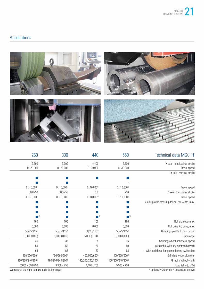
21MÄGERLE
GRINDING SYSTEMS
260 330 440 550 Technical data MGC FT
2,600 3,300 4,400 5,500 X-axis - longitudinal stroke
0...20,000 0...20,000 0...30,000 0...30,000 Travel speed
- - - - Y-axis - vertical stroke
■ ■ ■ ■
■ ■ - -
0...10,0001) 0...10,0001) 0...10,0001) 0...10,0001) Travel speed
500/750 500/750 750 750 Z-axis - transverse stroke
0...10,0001) 0...10,0001) 0...10,0001) 0...10,0001) Travel speed
■ ■ ■ ■ V-axis profile dressing device, roll width, max.
■ ■ ■ ■
■ ■ ■ ■
■ 2) ■ 2) ■ 2) ■ 2)
160 160 160 160 Roll diameter max.
6,000 6,000 6,000 6,000 Roll drive AC drive, max.
50/75/1151) 50/75/1152) 50/75/1152) 50/75/1152) Grinding spindle drive – power
5,000 (8,000) 5,000 (8,000) 5,000 (8,000) 5,000 (8,000) Rpm range
35 35 35 35 Grinding wheel peripheral speed
50 50 50 50 – switchable with key-operated switch
63 63 63 63 – with additional flange monitoring switchable
400/500/6002) 400/500/6002) 400/500/6002) 400/500/6002) Grinding wheel diameter
160/200/240/3002) 160/200/240/3002) 160/200/240/3002) 160/200/240/3002) Grinding wheel width
2,600 x 500/750 3,300 x 750 4,400 x 750 5,500 x 750 Fixed table (L x W)
We reserve the right to make technical changes 1) optionally 20m/min 2) dependent on size
Bitte komplette Tabellenübersetzung anliefern
Applications
22 MÄGERLE
GRINDING SYSTEMS
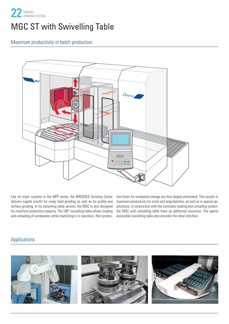
MGC ST with Swivelling Table
Like its sister systems in the MFP series, the MÄGERLE Grinding Center
delivers superb results for creep feed grinding as well as for profile and
surface grinding. In its swivelling table version, the MGC is also designed
for maximum production capacity. The 180° swivelling table allows loading
and unloading of workpieces while machining is in operation. Non-produc-
tive times for workpiece change are thus largely eliminated. This results in
maximum productivity for small and large batches, as well as in special ap-
plications. In conjunction with the automatic loading and unloading system,
the MGC with swivelling table frees up additional resources. The openly
accessible swivelling table also provides the ideal interface.
Maximum productivity in batch production
Applications
23MÄGERLE
GRINDING SYSTEMS
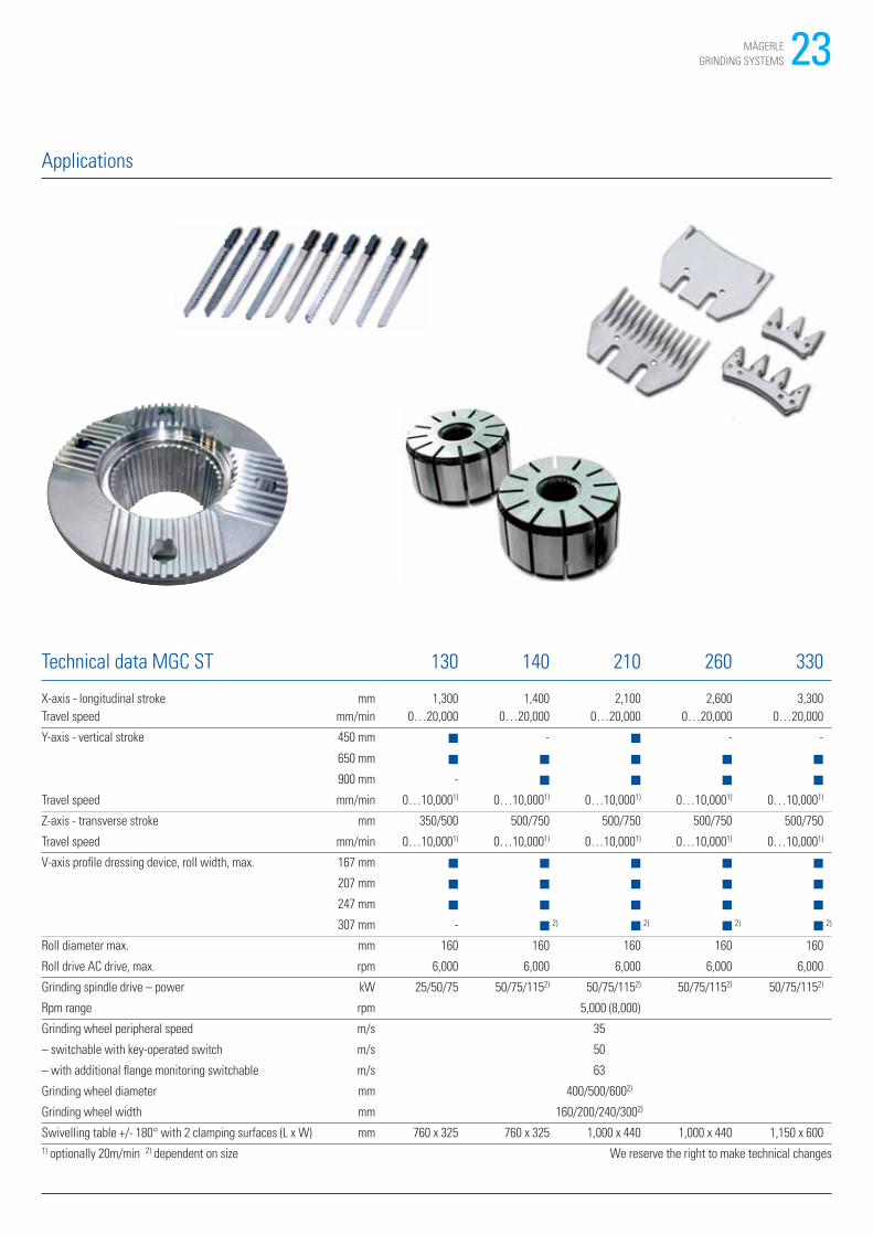
Applications
Technical data MGC ST 130 140 210 260 330
X-axis - longitudinal stroke mm 1,300 1,400 2,100 2,600 3,300
Travel speed mm/min 0…20,000 0…20,000 0…20,000 0…20,000 0…20,000
Y-axis - vertical stroke 450 mm ■ - ■ - -
650 mm ■ ■ ■ ■ ■
900 mm - ■ ■ ■ ■
Travel speed mm/min 0…10,0001) 0…10,0001) 0…10,0001) 0…10,0001) 0…10,0001)
Z-axis - transverse stroke mm 350/500 500/750 500/750 500/750 500/750
Travel speed mm/min 0…10,0001) 0…10,0001) 0…10,0001) 0…10,0001) 0…10,0001)
V-axis profile dressing device, roll width, max. 167 mm ■ ■ ■ ■ ■
207 mm ■ ■ ■ ■ ■
247 mm ■ ■ ■ ■ ■
307 mm - ■ 2) ■ 2) ■ 2) ■ 2)
Roll diameter max. mm 160 160 160 160 160
Roll drive AC drive, max. rpm 6,000 6,000 6,000 6,000 6,000
Grinding spindle drive – power kW 25/50/75 50/75/1152) 50/75/1152) 50/75/1152) 50/75/1152)
Rpm range rpm 5,000 (8,000)
Grinding wheel peripheral speed m/s 35
– switchable with key-operated switch m/s 50
– with additional flange monitoring switchable m/s 63
Grinding wheel diameter mm 400/500/6002)
Grinding wheel width mm 160/200/240/3002)
Swivelling table +/- 180° with 2 clamping surfaces (L x W) mm 760 x 325 760 x 325 1,000 x 440 1,000 x 440 1,150 x 600
1) optionally 20m/min 2) dependent on size We reserve the right to make technical changes
24 MÄGERLE
GRINDING SYSTEMS
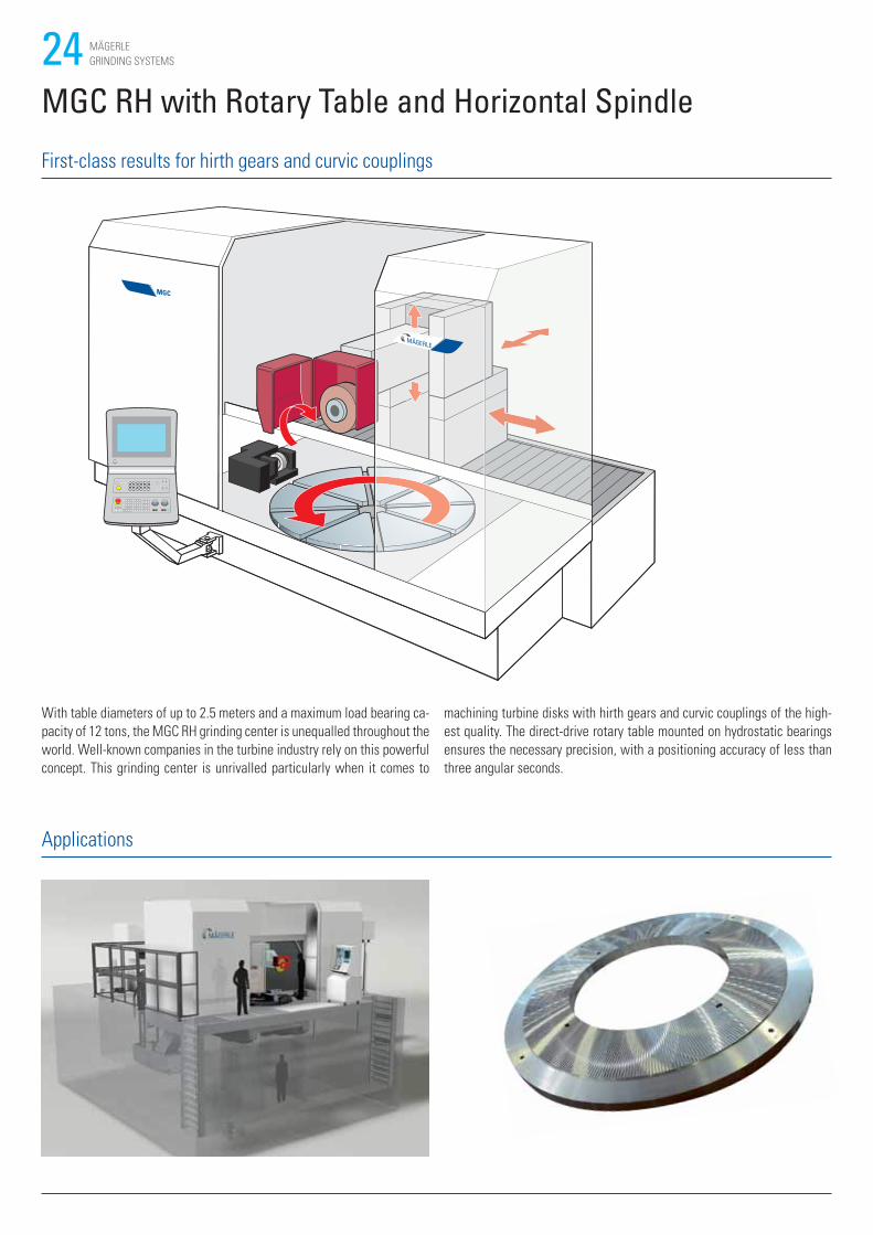
MGC RH with Rotary Table and Horizontal Spindle
With table diameters of up to 2.5 meters and a maximum load bearing ca-
pacity of 12 tons, the MGC RH grinding center is unequalled throughout the
world. Well-known companies in the turbine industry rely on this powerful
concept. This grinding center is unrivalled particularly when it comes to
machining turbine disks with hirth gears and curvic couplings of the high-
est quality. The direct-drive rotary table mounted on hydrostatic bearings
ensures the necessary precision, with a positioning accuracy of less than
three angular seconds.
First-class results for hirth gears and curvic couplings
Applications
25MÄGERLE
GRINDING SYSTEMS
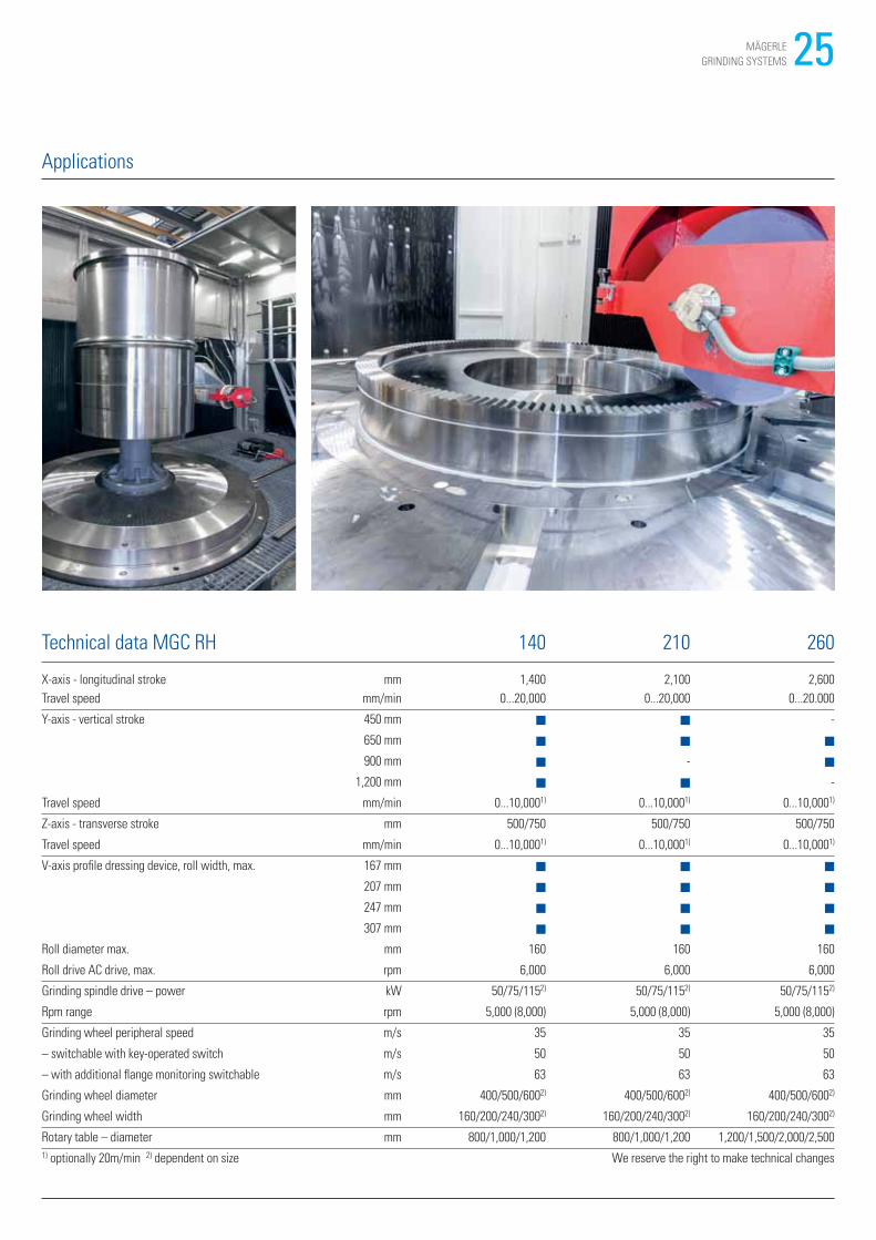
Applications
Technical data MGC RH 140 210 260
X-axis - longitudinal stroke mm 1,400 2,100 2,600
Travel speed mm/min 0...20,000 0...20,000 0...20.000
Y-axis - vertical stroke 450 mm ■ ■ -
650 mm ■ ■ ■
900 mm ■ - ■
1,200 mm ■ ■ -
Travel speed mm/min 0...10,0001) 0...10,0001) 0...10,0001)
Z-axis - transverse stroke mm 500/750 500/750 500/750
Travel speed mm/min 0...10,0001) 0...10,0001) 0...10,0001)
V-axis profile dressing device, roll width, max. 167 mm ■ ■ ■
207 mm ■ ■ ■
247 mm ■ ■ ■
307 mm ■ ■ ■
Roll diameter max. mm 160 160 160
Roll drive AC drive, max. rpm 6,000 6,000 6,000
Grinding spindle drive – power kW 50/75/1152) 50/75/1152) 50/75/1152)
Rpm range rpm 5,000 (8,000) 5,000 (8,000) 5,000 (8,000)
Grinding wheel peripheral speed m/s 35 35 35
– switchable with key-operated switch m/s 50 50 50
– with additional flange monitoring switchable m/s 63 63 63
Grinding wheel diameter mm 400/500/6002) 400/500/6002) 400/500/6002)
Grinding wheel width mm 160/200/240/3002) 160/200/240/3002) 160/200/240/3002)
Rotary table – diameter mm 800/1,000/1,200 800/1,000/1,200 1,200/1,500/2,000/2,500
1) optionally 20m/min 2) dependent on size We reserve the right to make technical changes
26 MÄGERLE
GRINDING SYSTEMS
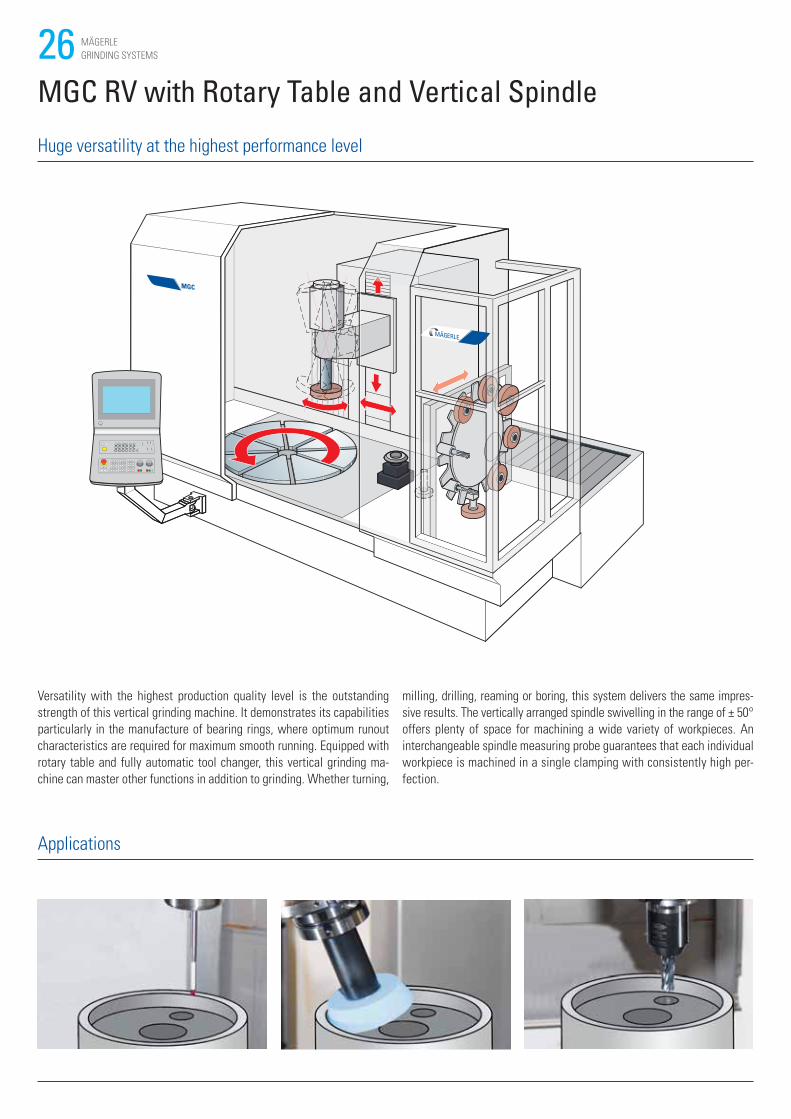
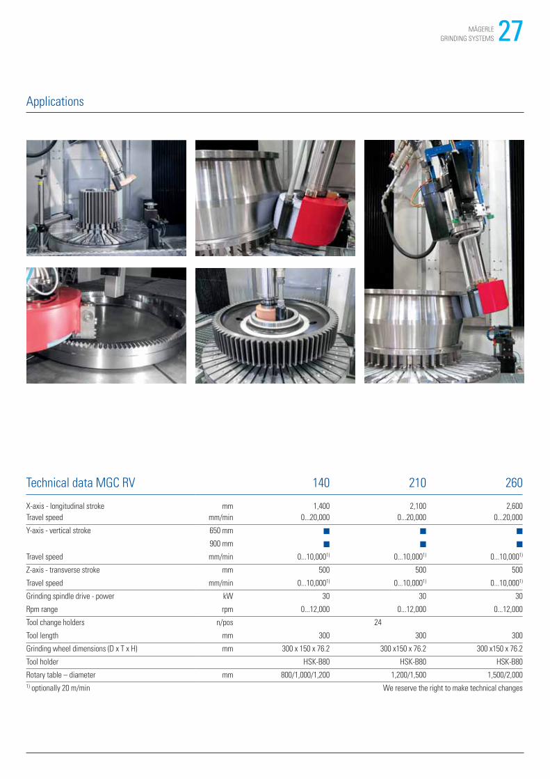
MGC RV with Rotary Table and Vertical Spindle
Versatility with the highest production quality level is the outstanding
strength of this vertical grinding machine. It demonstrates its capabilities
particularly in the manufacture of bearing rings, where optimum runout
characteristics are required for maximum smooth running. Equipped with
rotary table and fully automatic tool changer, this vertical grinding ma-
chine can master other functions in addition to grinding. Whether turning,
milling, drilling, reaming or boring, this system delivers the same impres-
sive results. The vertically arranged spindle swivelling in the range of ± 50°
offers plenty of space for machining a wide variety of workpieces. An
interchangeable spindle measuring probe guarantees that each individual
workpiece is machined in a single clamping with consistently high per-
fection.
Huge versatility at the highest performance level
Applications
27MÄGERLE
GRINDING SYSTEMS
Technical data MGC RV 140 210 260
X-axis - longitudinal stroke mm 1,400 2,100 2,600
Travel speed mm/min 0...20,000 0...20,000 0...20,000
Y-axis - vertical stroke 650 mm ■ ■ ■
900 mm ■ ■ ■
Travel speed mm/min 0...10,0001) 0...10,0001) 0...10,0001)
Z-axis - transverse stroke mm 500 500 500
Travel speed mm/min 0...10,0001) 0...10,0001) 0...10,0001)
Grinding spindle drive - power kW 30 30 30
Rpm range rpm 0...12,000 0...12,000 0...12,000
Tool change holders n/pos 24
Tool length mm 300 300 300
Grinding wheel dimensions (D x T x H) mm 300 x 150 x 76.2 300 x150 x 76.2 300 x150 x 76.2
Tool holder HSK-B80 HSK-B80 HSK-B80
Rotary table – diameter mm 800/1,000/1,200 1,200/1,500 1,500/2,000
1) optionally 20 m/min We reserve the right to make technical changes
Applications
28 MÄGERLE
GRINDING SYSTEMS
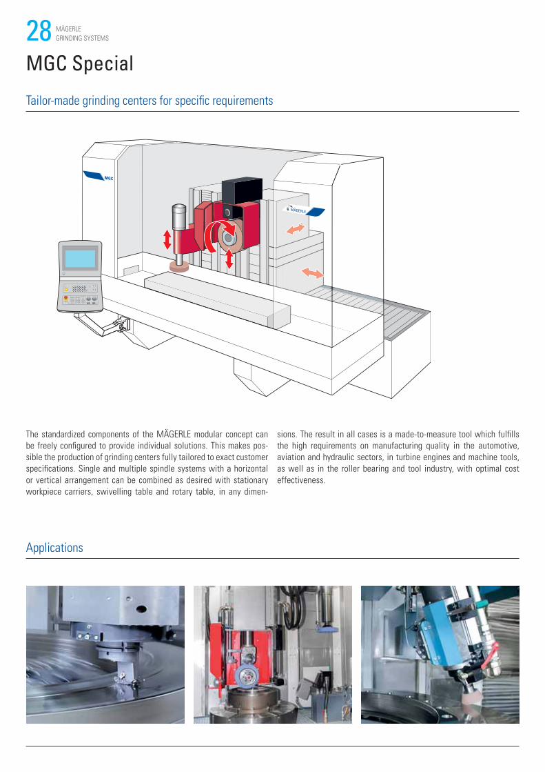
MGC Special
The standardized components of the MÄGERLE modular concept can
be freely configured to provide individual solutions. This makes pos-
sible the production of grinding centers fully tailored to exact customer
specifications. Single and multiple spindle systems with a horizontal
or vertical arrangement can be combined as desired with stationary
workpiece carriers, swivelling table and rotary table, in any dimen-
sions. The result in all cases is a made-to-measure tool which fulfills
the high requirements on manufacturing quality in the automotive,
aviation and hydraulic sectors, in turbine engines and machine tools,
as well as in the roller bearing and tool industry, with optimal cost
effectiveness.
Tailor-made grinding centers for specific requirements
Applications
29MÄGERLE
GRINDING SYSTEMS
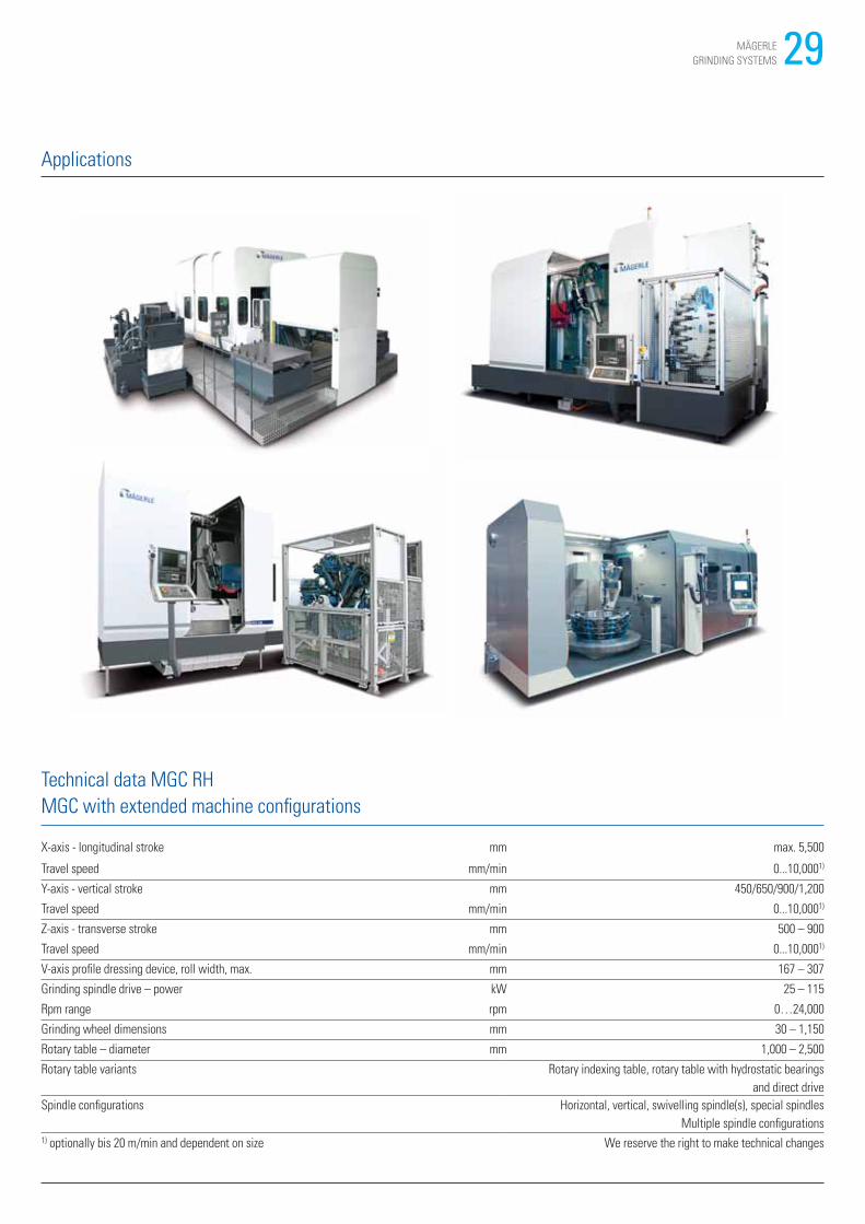
Technical data MGC RH
MGC with extended machine configurations
X-axis - longitudinal stroke mm max. 5,500
Travel speed mm/min 0...10,0001)
Y-axis - vertical stroke mm 450/650/900/1,200
Travel speed mm/min 0...10,0001)
Z-axis - transverse stroke mm 500 – 900
Travel speed mm/min 0...10,0001)
V-axis profile dressing device, roll width, max. mm 167 – 307
Grinding spindle drive – power kW 25 – 115
Rpm range rpm 0…24,000
Grinding wheel dimensions mm 30 – 1,150
Rotary table – diameter mm 1,000 – 2,500
Rotary table variants Rotary indexing table, rotary table with hydrostatic bearings
and direct drive
Spindle configurations Horizontal, vertical, swivelling spindle(s), special spindles
Multiple spindle configurations1) optionally bis 20 m/min and dependent on size We reserve the right to make technical changes
Applications
30 MÄGERLE
GRINDING SYSTEMS
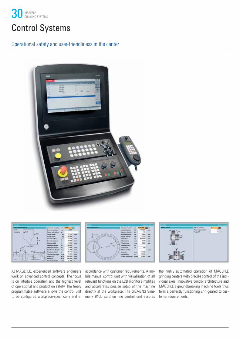
Control Systems
At MÄGERLE, experienced software engineers
work on advanced control concepts. The focus
is on intuitive operation and the highest level
of operational and production safety. The freely
programmable software allows the control unit
to be configured workpiece-specifically and in
accordance with customer requirements. A mo-
bile manual control unit with visualization of all
relevant functions on the LCD monitor simplifies
and accelerates precise setup of the machine
directly at the workpiece. The SIEMENS Sinu-
merik 840D solution line control unit assures
the highly automated operation of MÄGERLE
grinding centers with precise control of the indi-
vidual axes. Innovative control architecture and
MÄGERLE's groundbreaking machine tools thus
form a perfectly functioning unit geared to cus-
tomer requirements.
Operational safety and user-friendliness in the center
31MÄGERLE
GRINDING SYSTEMS
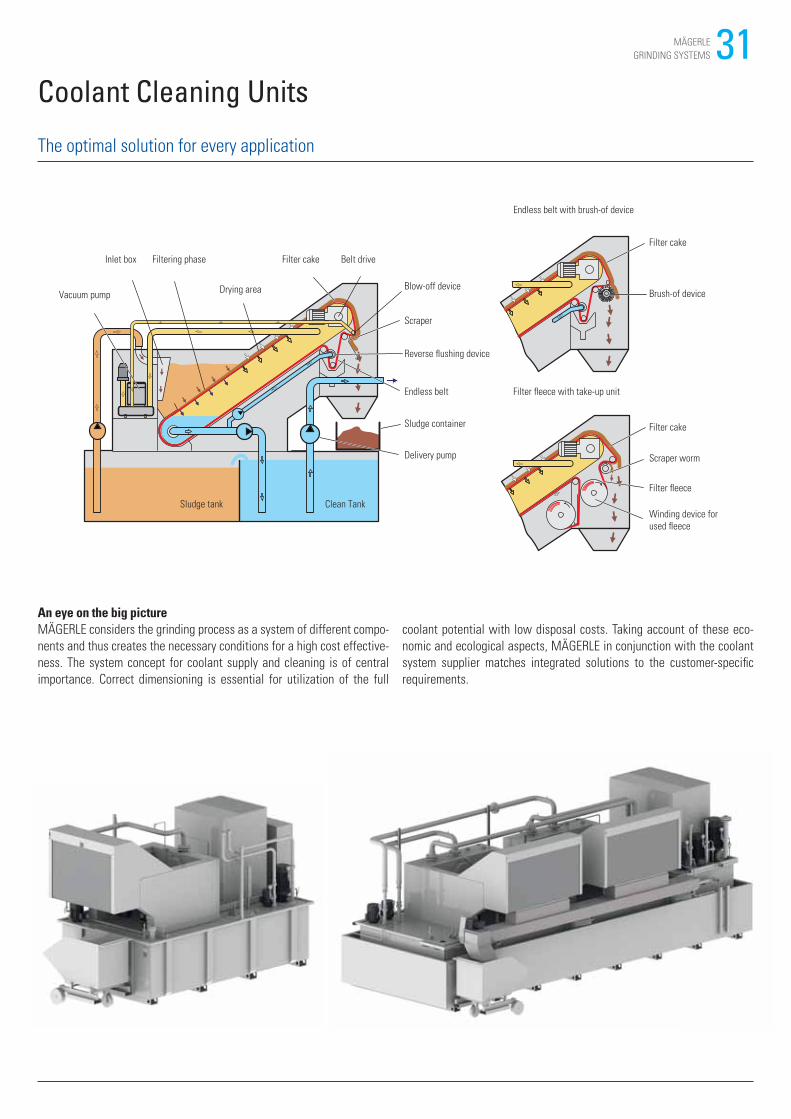
An eye on the big pictureMÄGERLE considers the grinding process as a system of different compo-
nents and thus creates the necessary conditions for a high cost effective-
ness. The system concept for coolant supply and cleaning is of central
importance. Correct dimensioning is essential for utilization of the full
The optimal solution for every application
Coolant Cleaning Units
Belt driveFiltering phase Filter cakeInlet box
Vacuum pumpDrying area Brush-of device
Filter cake
Filter cake
Scraper worm
Filter fleece
Winding device for
used fleece
Endless belt with brush-of device
Blow-off device
Scraper
Reverse flushing device
Endless belt
Sludge container
Delivery pump
Sludge tank Clean Tank
Filter fleece with take-up unit
coolant potential with low disposal costs. Taking account of these eco-
nomic and ecological aspects, MÄGERLE in conjunction with the coolant
system supplier matches integrated solutions to the customer-specific
requirements.
32 MÄGERLE
GRINDING SYSTEMS
Customer Care
MÄGERLE surface and profile grinding machines should fulfill the
customer›s requirements for as long as possible, work cost-effectively,
function reliably and be available at all times. From “start up” through to
“retrofit” – our Customer Care is there for you throughout the working life
of your machine. 3 professional helplines are available in your area, whe-
rever you are in the world.
• We will provide you with fast, uncomplicated support.
• We will help to increase your productivity.
• We work professionally, reliably and transparently.
• We will provide a professional solution to your problems.
Prevention
Maintenance – Your advantages:• Increased machine availability thanks to
reduced downtime
• Higher and more constant production quality
• Well-founded statements on the machine
condition
• Cost transparency thanks to flat rate
Inspection – Your advantages:• Early identification of defects
• Service tasks easier to schedule
• Increased machine availability thanks to
reduced downtime
Start up
Commissioning – Your advantages:• Smooth start to production
• Optimal basic knowledge
• Trained staff
Warranty extension – Your advantages:• Ability to plan
• Financial security at low additional costs
Qualification Training – Your advantages:• Learning of processes under real conditions
• Trained and motivated staff
• Increased productivity
• Lower risk of a machine failure due to incor-
rect operation
Production support – Your advantages:• Increase in your company’s know-how
• Support of your production team by our
specialists
• Increased productivity
33MÄGERLE
GRINDING SYSTEMS
Service
Customer service – Your advantages:• Fast response times thanks to locally based
service technicians
• Rapid troubleshooting
• Quick and effective problem solving
Customer consultation – Your advantages:• Availability of expert consultants
• Individual consultation
HelpLine – Your advantages:• Personal contact
• Increased machine availability thanks to fast
response times
Material
Spare parts – Your advantages:• Fast and flexible response to your requirements
• Fitting accuracy and process reliability thanks
to original spare parts
• High precision is maintained
Replacement parts – Your advantages:• Lower costs when purchasing replacement
parts
• Fast problem-solving
• Replacement parts that are a perfect fit
Accessories – Your advantages:• Customisation of your machine
• Accessories that are a perfect fit
Digital SolutionsTM
Remote Service• Service request at the touch of a button
• Increased availability of your system
• Minimise downtimes
Service Monitor• Structured maintenance planning
• Easier maintenance thanks to guides and
instructions
• Maintenance documentation available online
Production Monitor• Information and key data about your machines
– around the clock
• Support for your planners and production staff
• Data for optimisation of availability and
utilisation
Rebuild
Machine overhaul – Your advantages:• Same precision and productivity as a new
machine
• Extended service life of your machine
• Retraining of employees on a new machine
unnecessary
Assembly overhaul – Your advantages:• You receive an assembly that’s as good as new
• Extended service life of the machine
• Rectification of geometry problems
Retrofit
Conversions – Your advantages:• Use your machine for new applications
• Extended service life of the machine
• Retraining of employees on a new machine
unnecessary
Retrofits – Your advantages:• Retrofitting of components to the current state
of the art
• Preservation of your machine’s value
• Your machine remains in-situ

34 MÄGERLE
GRINDING SYSTEMS
35MÄGERLE
GRINDING SYSTEMS
MÄ
GER
LE G
RIN
DIN
G S
YS
TEM
S ·
V4.
1 · 0
1/20
21 ·
en
Mägerle AG Maschinenfabrik
Allmendstrasse 50
CH - 8320 Fehraltorf
Phone +41 43 355 66 00
Fax +41 43 355 65 00
www.maegerle.com