Embed Size (px)
Citation preview

MGE Galaxy PW150–225 kVA 480 V
Installation


Table of ContentsSafety ........................................................................................................................................ 1
SAVE THESE INSTRUCTIONS ..................................................................................... 1Symbols used .................................................................................................................... 1
Installation Procedure ............................................................................................................... 3Installation Overview................................................................................................................ 4
General Description .......................................................................................................... 4Major System Power Components ................................................................................... 4Galaxy PW Cabinet........................................................................................................... 6Battery Cabinet ................................................................................................................. 7External Maintenance Bypass Cabinet ............................................................................. 8
Specifications ............................................................................................................................ 9Electrical Parameters for Selecting Protective Devices.................................................... 9Recommended Current Protection....................................................................................10Parallel UPS Units ............................................................................................................11
Connect the Power Cables ........................................................................................................12Wiring Diagrams...............................................................................................................12
Connections between Cabinets .................................................................................................15Connect Cables Between UPOZ Boards...................................................................................15MUSI Board Connections.........................................................................................................16Connect Cables Between MUSI Boards with Two Parallel UPS Units....................................16Connect Cables Between MUSI Boards with Three Parallel UPS Units .................................17Connect Cables Between MUSI Boards with Four Parallel UPS Units ...................................18
Optional Communication Card Installation ......................................................................19Media Contacts 11 Board..................................................................................................20
Installation of the Temperature Monitor ...................................................................................23Install the Temperature Monitor in the Battery Cabinet ...........................................................23Install Temperature Monitor Base in Battery Room.................................................................23
Connection of the Battery Temperature Monitor..............................................................24Final Installation Steps..............................................................................................................26
990–4219–001 MGE Galaxy PW 150–225 kVA 480 V i

ii MGE Galaxy PW 150–225 kVA 480 V 990–4219–001

Safety
SAVE THESE INSTRUCTIONS
This manual contains important instructions for the Galaxy PW™ that must be followed duringoperation of the equipment.
WARNING: Opening enclosures expose hazardous voltages. Always refer service toqualified personnel only.
WARNING: As standards, specifications, and designs are subject to change, pleaseask for confirmation of the information given in this document.
Note: The equipment has been tested and found to comply with the limits for a ClassA digital device, pursuant to part 15 of the FCC rules. These limits are designed toprovide reasonable protection against harmful interference when the equipment isoperated in a commercial environment. The equipment generates, uses, and can radiateradio frequency energy and, if not installed and used in accordance with the instructionmanual, may cause harmful interference to radio communications. Operation of thisequipment in a residential area is likely to cause harmful interference in which case theuser will be required to correct interference at user’s own expense.
WARNING: To reduce the risk of fire or electric shock, install in a temperature andhumidity controlled indoor area free of conductive contaminants. This equipment isintended only for installation in RESTRICTED ACCESS LOCATION.
WARNING: HIGH LEAKAGE CURRENT. Earth connection essential beforeconnecting supply.
Symbols usedWARNING: Indicates an electrical hazard, which, if not avoided, could result ininjury or death.
Caution: Indicates a hazard, which, if not avoided, could result in injury or death.
Note: Indicates important information.
990–4219–001 MGE Galaxy PW 150–225 kVA 480 V 1

See: Indicates that more information is available on this subject.
2 MGE Galaxy PW 150–225 kVA 480 V 990–4219–001

Installation Procedure
1. Unpack and position the unit.
2. Connect the mains/utility power.
3. Connect the power circuits.
4. Call Schneider Electric and wait for the service engineer to complete the installation.
5. The Schneider Electric service engineer finalizes the installation and the start-up process.
990–4219–001 MGE Galaxy PW 150–225 kVA 480 V 3

Installation Overview
General Description
The cabinets are cooled by forced ventilation. The air enters via the doors and grids at the bottom andis discharged through the roof, which means the cabinets can be positioned against the back wall.
Connections are made through the bottom (connections through the top are an available option).
The connection cables may be run in three ways:
• In a trench running under the cabinets
• Under a false floor
• On the floor under the cabinets, in the free space equal to the height of the feet; in this case thecables should be run side by side to avoid blocking the flow of air for ventilation.
The cables should be connected:
• To the normal AC input terminals
• To the bypass AC input terminals
• Between the battery and UPS cabinets (power and control cables)
• Between the bypass AC-source transformer in an auxiliary cabinet and the UPS cabinet
Only the wires for the inter-cabinet control connections between parallel-connected UPS units aresupplied.
The other power cables for connections between the cabinets are not supplied.
Major System Power Components
Single UPS system
maintenance bypass:Q3BP
inverter (B):DC to ACpower
isolation:Q4S
isolation andprotection:
Q5N
rectifier/charger (A):AC to DCpower
QF1: isolationand protection
normalAC input
load
battery (D):backup power
static bypass (C):
bypassAC input
Q1 isolationandprotection
(1)
(2)
harmonicfliter
*FUSE*FUSE
4 MGE Galaxy PW 150–225 kVA 480 V 990–4219–001

Component Description
Rectifier/charger module (A) Converts 3–phase AC power from the normal ACsource supply (1) into DC power for the normalinverter input and float charges or recharges thebattery.
Battery unit (D) Provides backup power for the inverter in theevent of a voltage drop or a normal AC sourcefailure.
Inverter module (B) Converts the DC power supplied by therectifier/charger module or the battery unit into3–phase AC power for the load.
Static bypass module (C) Ensures the instantaneous transfer of the load tothe bypass AC source input in the event of aninverter shutdown (initiated by the user or by aprotective device) or a sudden load.
Maintenance bypass Isolates the UPS for maintenance and transfersthe load to bypass AC source input withoutinterrupting the supply of power. Themaintenance bypass is made up of three manualswitches (Q3BP, Q4S and Q5N).
External bypass Option for parallel UPSs and hot-swapping.Q1 (molded circuit breaker NA) Isolation of the rectifier/charter (A) from the
normal AC source (1).QF1 (circuit breaker) Battery (D) protection and isolation.Q5N (switch) Isolation of the UPS system from the load.Q4S (switch) Isolation of the static bypass (C) from the bypass
AC source.Q3BP (switch) Bypass for maintenance.
The normal AC input and the bypass AC input have different functions and, depending in theinstallation, may be protected differently upstream and/or come from different sources.
When increased power is required, several UPS units may be connected in parallel (up to four). In thisconfiguration, an isolation function is added for the UPS system as a whole for maintenance purposes,without interrupting the supply of power to the load.
990–4219–001 MGE Galaxy PW 150–225 kVA 480 V 5

Galaxy PW Cabinet
H
G
G
H
F E1
P
2
G
Y
Q1
Q4S Q5NQ3BP
L1L2L3L1L2L3 L1L2L3GND N
M
QZ
S
L
AB
M N 3
T
W
U
R
A
X
J
I
1, 2, E,F
DC
AA
K O
V
AA: Cross-sectional view of the cabinet
B: Front view of the cabinet
C: Front panel
D: Rear panel
1: Normal AC input connection
2: Bypass AC input connection
E: Load connection
F: Battery connection
G: Air inlets
H: Air outlets
I: Cable exit through the bottom
J: Trough, if applicable
K: Rectifier/charger module
L: Inverter module
M: Static-bypass module
N: Rack containing electronic boards
O: Media Contacts 11 board
P: Slot for communication boards
Q: FUE input fuses
R: FUS output fuses
S: RALI board
T: UPOZ board
U: MUSI board
V: Backfeed protection (contactor)
W: Control wire routing
X: Fuses for overvoltage protection RC circuiton bypass
Y: Control-wire connection (auxiliary “MediaContacts 11” circuits and communicationoptions)
Z: EP0I board
3: VETI board
6 MGE Galaxy PW 150–225 kVA 480 V 990–4219–001

Battery Cabinet
990–4219–001 MGE Galaxy PW 150–225 kVA 480 V 7

External Maintenance Bypass Cabinet
F1, F2
TRANSFER INITIATE (SI)
ELECTRIC INTERLOCK(KA)
350A
CRITICAL LOAD
TB1
MBPTERMINALS
NEUTRAL
CB2UPS ISOLATION
CB1MAINTENANCEBYPASS
UPSTERMINALS
GROUND
1200ANEURTRAL
(NOT SHOWN )
CRITICAL LOAD
DISPLAY METER
T1
MAINTENANCE
BYPASS
GROUND
REMOVABLE
PANELS
FOR POWER
CONDUIT ENTRY
SEISMIC
MOU NTING
CUTOUTS
SEISMIC HOLE
LOCATION
FORKLIFT OPENINGS
(LEFT & RIGHT
SIDE TYPICAL)
MULTI CIRCUIT
MON ITOR BOARD
MULTI CIRCUIT
MON ITOR BOARD
F1, F2
F3 TO F8
TRANSFER INITIATE (SI)
ELECTRIC INTERLOCK
(KA)
TB2
CB2
CB1
UPS OUTPUT
TB1
CONTROL WIRE
ROUTING
REMOVABLE PANEL
FOR CONTROL AND
POW ER
CONDUIT ENTRY
8 MGE Galaxy PW 150–225 kVA 480 V 990–4219–001

Specifications
Electrical Parameters for Selecting ProtectiveDevices
Normal AC Source
The parameters given in the table below can be used to determine the required rating of the upstreamprotective circuit breaker on the normal AC input for one single-UPS or parallel-UPS unit.
Note: It is essential to choose the type of circuit breaker according to its breakingcapacity and the prospective short-circuit current at its place of installation. This choicemust also be made so as to protect the static-switch semiconductors with respect to themaximum permissible currents and ensure discrimination between the UPS output fusesand the downstream protection devices.
Normal AC sourceRated current
Rated output inkVA
With battery atstart of cycle1
Without battery225% overload3 50% overload3
150 245 236 295 354180 295 283 354 425200 328 316 395 474225 332 320 400 480Notes:1 The rated normal AC source currents (In) have been determined for a rated phase-to-phase voltageof 480 V, a battery with a 10 minute backup time at the beginning of its charge (412 x 1, 2 = 494Volts) and full rated load with a power factor of 0.9.2 The rated normal AC source currents (In) have been determined for float charging voltage and fullrated load with a power factor of 0.9.3 The normal AC source currents given for an overload of 25% or 50% are maximum values. Theyhave been determined for a battery with float charging voltage and a load power factor of 0.9. Whenchoosing the circuit breaker rating, use the "rated current" column and check that the circuit breakertripping curves are compatible with the values in the overload columns.
990–4219–001 MGE Galaxy PW 150–225 kVA 480 V 9

Bypass AC Source
The parameters given in the tables below can be used to determine the required rating of the upstreamprotective circuit breaker on bypass AC input.
Note: If the installation includes a transformer on the bypass AC input, allow for theinrush current caused by magnetization of the transformer windings.
Bypass AC sourceRated output in kVARated current 25% overload 50% overload
150 180 236 270180 217 283 325200 241 316 362225 271 320 407Notes:
The bypass AC source currents have been determined for a rated phase-to-phase voltage of 480 V, aload power factor of 0.9 and for full rated load as well as overloads of 25% or 50%. When choosingthe circuit breaker rating, use the "rated current" column and check that the circuit breaker trippingcurves are compatible with the data in the overload columns. See table and chart below.
UPS output in kVA Maximum permissible current150 33 In for 20 ms180 27 In for 20 ms200 25 In for 20 ms225 22 In for 20 ms
Recommended Current Protection
Upstream Protection
The information provided here is purely indicative for a single UPS unit. Check that all the criteriaunder electrical parameters are taken into account.
CB in normal AC input CB in bypass AC inputRated UPS outputin kVA Circuit Breaker Control unit Circuit Breaker Control unit150 250 A 250 A 250 A 250 A180 250 A 250 A 250 A 250 A200 400 A 400 A 400 A 400 A225 400 A 400 A 400 A 400 A
10 MGE Galaxy PW 150–225 kVA 480 V 990–4219–001

Downstream Protection
These protection devices ensure discrimination for each of the output circuits. If the recommendeddownstream protection is not installed and a short-circuit occurs, the result may be a break longer than20 ms on all the other output circuits.
Downstream circuit breaker(s)Rated UPS output in kVACircuit Breaker Control unit
150–225 kVA 100 A 63 A curve C, 100 A curve B
Parallel UPS UnitsFor installations with redundant units, take into account only the units required to supply the loadpower (e.g. for an installation with three parallel-connected UPS units, one being redundant, only twounits are used to determine bypass AC source and load currents and cable cross-sections.
Rated unit output inkVA
Number ofparallel-connectedunits
Total UPS rated outputin kVA
Bypass AC source orload line current inAmps
2 300 3603 450 540
150
4 600 7202 360 4343 540 651
180
4 720 8682 400 4823 600 723
200
4 800 9642 450 5423 675 813
225
4 900 1084
990–4219–001 MGE Galaxy PW 150–225 kVA 480 V 11

Connect the Power Cables
WARNING: Before making connections, check that switches Q1, Q4S, Q3BP, Q5Nand QF1 are in the "open" position.
Note: For parallel UPS with an external bypass unit, the power connections betweeneach UPS cabinet and the external bypass cabinet must imperatively be of the samelength. Separate the auxiliary control wiring from the power cables.
1. Open the doors.
2. Remove the lower terminal shields (secured by screws to the cabinet chassis).
3. Connect the power cables according to the wiring diagram for your specific system.
4. Connect ground cables to each cabinet.
Wiring Diagrams
Single UPS
The single UPS wire diagram is for typical UPS installations shown below. The heavy lines representthe cables that must be connected (F).
1 Normal AC source2 Bypass AC sourceA Rectifier/charger moduleB Inverter moduleC Static-bypass moduleD Battery cabinet next to the Galaxy PW™ UPS cabinetE Additional battery cabinetsF The equipotential bonding connection between cabinets
2
1
C
BA
Q4S
D+ – + –
E
F
QF1
Q1 Q5N
Galaxy PW
F
Q3BP( )
( )
12 MGE Galaxy PW 150–225 kVA 480 V 990–4219–001

Single UPS with External Bypass
The external bypass may be used to construct a bypass outside the UPS, thus making it possible toshutdown the UPS for maintenance purposes.
Power cables for UPS-to-bypass connections are not supplied.
1 Normal AC sourceA Rectifier/charger module2 Bypass AC sourceB Inverter module
C Static-bypass moduleD Battery cabinet next to the Galaxy PW™ UPS cabinetE Additional battery cabinetsF The equipotential-bonding connection between cabinets
C
BA
Q4S
Q1 Q5N
Galaxy PW
Q3BP
2
1
D+ – + –
E
F
QF1
F
Q4S2
Q3BP
Q5N
( )
( )( )
( )
990–4219–001 MGE Galaxy PW 150–225 kVA 480 V 13

Parallel UPS
The external bypass may be used to construct a bypass outside the UPS, thus making it possible toshutdown the UPS for maintenance purposes.
Power cables for UPS-to-bypass connections are not supplied.
1 Normal AC source2 Bypass AC sourceA Rectifier/charger moduleB Inverter module
C Static-bypass moduleD Battery cabinet next to the Galaxy PW™ UPS cabinetE Additional battery cabinetsF The equipotential-bonding connection between cabinets
Galaxy PW
2
1
D+ – + –
E
F
QF1
F
2
1
D+ – + –
E
F
QF1
F
Galaxy PW
2
Q3BP
Q5N
2
C
BA
Q4S
Q1 Q5N( )
( )
C
BA
Q4S
Q1 Q5N( )
( )
( )
14 MGE Galaxy PW 150–225 kVA 480 V 990–4219–001

Connections between Cabinets
The connections between the cabinets are made on the UPOZ board (marked T) and MUSI board(marked U).
H
G
G
H
F E1
P
2
G
Y
Q1
Q4S Q5NQ3BP
L1L2L3L1L2L3 L1L2L3GND N
M
QZ
S
L
AB
M N 3
T
W
U
R
A
X
J
I
1, 2, E,F
DC
AA
K O
V
Connect Cables Between UPOZ BoardsThese connections are made using the supplied cables. The purpose of the connection is to make a loop.
'UPOZ'Galaxy PWTM 1
'UPOZ'Galaxy PWTM 2
'UPOZ'Galaxy PWTM 3
XM136
XM137
XM136
XM137
XM136
XM137
A
1. Connect cable from XM138 on the first UPOZ board to XM137 on the next board.
2. Continue until you connect the cable to XM137 on the last UPOZ board.
990–4219–001 MGE Galaxy PW 150–225 kVA 480 V 15

3. On the last UPOZ board, connect cables from XM138 to XM137 on the first UPOZ board.
MUSI Board ConnectionsNote: Group the "UPOZ" inter-board and "MUSI" inter-board connections with theinter-cabinet auxiliary connections, and separate this wiring from the power cables.
Connectors XM5, XM6 and XM7 on the MUSI board are used to transmit signals.
Connectors XM10, XM11 and XM12 on the MUSI board are used to receive signals.
Connect Cables Between MUSI Boards with Two Parallel UPS Units'MUSI'
Galaxy PWTM 1
'MUSI'Galaxy PWTM 2
A
XM10
XM11
XM12
XM5
XM6
XM7
XM10
XM11
XM12
XM5
XM6
XM7
1. Connect cable from XM5 on the MUSI board of the first UPS to XM10 of the MUSI boardof the second UPS.
2. Connect cable from XM5 on the MUSI board of the second UPS to XM10 of the MUSI boardof the first UPS.
16 MGE Galaxy PW 150–225 kVA 480 V 990–4219–001

Connect Cables Between MUSI Boards with Three Parallel UPS Units'MUSI'
Galaxy PWTM 1
'MUSI'Galaxy PWTM 2
A
XM5
XM6
XM7
XM5
XM6
XM7
'MUSI'Galaxy PWTM 3
XM5
XM6
XM7
XM10
XM11
XM12
XM10
XM11
XM12
XM10
XM11
XM12
1. Connect cable from XM5 on the MUSI board of the first UPS to XM11 of the MUSI boardof the last UPS.
2. Connect cable from XM6 on the MUSI board of the first UPS to XM10 of the MUSI boardof the second UPS.
3. Connect cable from XM5 on the MUSI board of the second UPS to XM11 of the MUSI boardof the first UPS.
4. Connect cable from XM6 on the MUSI board of the second UPS to XM10 of the MUSI boardof the last UPS.
5. Connect cable from XM5 on the MUSI board of the last UPS to XM11 of the MUSI boardof the second UPS.
6. Connect cable from XM6 on the MUSI board of the last UPS to XM10 of the MUSI boardof the first UPS.
990–4219–001 MGE Galaxy PW 150–225 kVA 480 V 17

Connect Cables Between MUSI Boards with Four Parallel UPS Units'MUSI'
Galaxy PWTM 1
'MUSI'Galaxy PWTM 2
A
XM5
XM6
XM7
XM5
XM6
XM7
'MUSI'Galaxy PWTM 3
XM5
XM6
XM7
'MUSI'Galaxy PWTM 4
XM5
XM6
XM7
XM10
XM11
XM12
XM10
XM11
XM12
XM10
XM11
XM12
XM10
XM11
XM12
1. Connect cable from XM5 on the MUSI board of the first UPS to XM12 of the MUSI boardof the last UPS.
2. Connect cable from XM6 on the MUSI board of the first UPS to XM11 of the MUSI board ofthe third UPS.
3. Connect cable from XM7 on the MUSI board of the first UPS to XM10 of the MUSI boardof the second UPS.
4. Connect cable from XM5 on the MUSI board of the second UPS to XM12 of the MUSI boardof the first UPS.
5. Connect cable from XM6 on the MUSI board of the second UPS to XM11 of the MUSI boardof the last UPS.
6. Connect cable from XM7 on the MUSI board of the second UPS to XM10 of the MUSI board ofthe third UPS.
7. Connect cable from XM5 on the MUSI board of the third UPS to XM12 of the MUSI boardof the second UPS.
18 MGE Galaxy PW 150–225 kVA 480 V 990–4219–001

8. Connect cable from XM6 on the MUSI board of the third UPS to XM11 of the MUSI boardof the first UPS.
9. Connect cable from XM7 on the MUSI board of the third UPS to XM10 of the MUSI boardof the last UPS.
10. Connect cable from XM5 on the MUSI board of the last UPS to XM12 of the MUSI board ofthe third UPS.
11. Connect cable from XM6 on the MUSI board of the last UPS to XM11 of the MUSI boardof the second UPS.
12. Connect cable from XM7 on the MUSI board of the last UPS to XM10 of the MUSI boardof the first UPS.
Optional Communication Card Installation
H
G
G
H
F E1
P
2
G
Y
Q1
Q4S Q5NQ3BP
L1L2L3L1L2L3 L1L2L3GND N
M
QZ
S
L
AB
M N 3
T
W
U
R
A
X
J
I
1, 2, E,F
DC
AA
K O
V
Installation of boards setup notes:
• Boards should not be installed with the UPS on.
• Boards must be pushed to the end of the slots to ensure correct installation.
• Board front plates must be screwed to the protective "Media Contacts 11" board cover.
• Wire routing holes are provided in the support for the "Media Contacts 11" board for tying downthe wires.
• The control wires must then be routed through the cableway marked "W".
990–4219–001 MGE Galaxy PW 150–225 kVA 480 V 19

Media Contacts 11 BoardTerminals XR2, XR3, XR4 and XR5 on the "Media Contacts 11" board of each type of unit canbe used to receive signals from the operating environment and to transmit signals concerning theoperating status of the UPS.
Signal Reception
The signals should be provided by volt-free contacts.
Signal Description
Emergency off An NC contact causes shutdown of the inverterand the rectifier/charger, opening of the batterycircuit breaker, blocking of the static bypassand activation of a relay contact on the "MediaContacts 11" board.
Battery room ventilation fault A ‘NO’ contact causes shutdown of therectifier/charger.
Battery circuit breaker QF1 closed A ‘NO’ contact prevents inverter start-up if thecircuit breaker is open.
Battery temperature A PC-board, placed near the battery, suppliesinformation on the battery temperature, thusenabling the rectifier/charger to regulate thebattery voltage.
"Auxiliary" signals Depending on the selected settings, these signalsmay be used to provoke:
• forced shutdown of the inverter (whatever thestatus of the bypass AC source)
• protected shutdown of the inverter (loadtransfer to the bypass AC source)
• limiting of the current drawn by therectifier/charger (programmable value) whensupplied by an engine generator set with aninsufficient power rating. The additionalpower required by the inverter is supplied bythe battery which discharges
• limiting of the battery charge current(programmable value) if the normal ACsource is replaced by an engine generator setwith an insufficient power rating
20 MGE Galaxy PW 150–225 kVA 480 V 990–4219–001
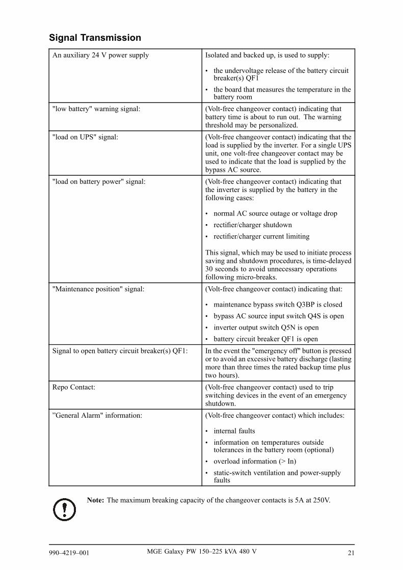
Signal Transmission
An auxiliary 24 V power supply Isolated and backed up, is used to supply:
• the undervoltage release of the battery circuitbreaker(s) QF1
• the board that measures the temperature in thebattery room
"low battery" warning signal: (Volt-free changeover contact) indicating thatbattery time is about to run out. The warningthreshold may be personalized.
"load on UPS" signal: (Volt-free changeover contact) indicating that theload is supplied by the inverter. For a single UPSunit, one volt-free changeover contact may beused to indicate that the load is supplied by thebypass AC source.
"load on battery power" signal: (Volt-free changeover contact) indicating thatthe inverter is supplied by the battery in thefollowing cases:
• normal AC source outage or voltage drop• rectifier/charger shutdown• rectifier/charger current limiting
This signal, which may be used to initiate processsaving and shutdown procedures, is time-delayed30 seconds to avoid unnecessary operationsfollowing micro-breaks.
"Maintenance position" signal: (Volt-free changeover contact) indicating that:
• maintenance bypass switch Q3BP is closed• bypass AC source input switch Q4S is open• inverter output switch Q5N is open• battery circuit breaker QF1 is open
Signal to open battery circuit breaker(s) QF1: In the event the "emergency off" button is pressedor to avoid an excessive battery discharge (lastingmore than three times the rated backup time plustwo hours).
Repo Contact: (Volt-free changeover contact) used to tripswitching devices in the event of an emergencyshutdown.
”General Alarm" information: (Volt-free changeover contact) which includes:
• internal faults• information on temperatures outside
tolerances in the battery room (optional)• overload information (> In)• static-switch ventilation and power-supply
faults
Note: The maximum breaking capacity of the changeover contacts is 5A at 250V.
990–4219–001 MGE Galaxy PW 150–225 kVA 480 V 21

Standard Auxiliary Circuits Connection
Recommended cable cross-section: 1 mm2. The male connectors that fit the female connectors on theboard (XR2 to XR5) are supplied. The contacts are volt-free and are shown in the diagram under thefollowing conditions: UPS on, contact at rest. Contact breaking capacity: 250 V, 5 A.
Media Contacts 11 Board
121110987654321
10987654321
-12V
-12V
24V CC-12V
XR3 connector
ACACAC
power supply
input or output signals:
input or output signals:
emergency shutdown breaker circuit REPO(jumper Y
XR2 connector
harmonic filter
battery cubicle
XA13 terminal block
correction with optional electric boad formeasuring battery temperature
temperaturesignal
OF1 battery circuit-breaker opening command
harmonics over-temperature fault
battery-room ventilation fault
-12V+12V
QF1 batterycircuit breakerclosed
QF1 batterycircuit breakeropening command
XA1 terminal block
output signals:
EPO
XR2 XR3 XR4 XR5
12 - - - - - - - - - -1 10 - - - - - - - -1 10 - - - - - - - -1 10 - - - - - - - -1
circuit
thermal measuringof theharmoinc-filtercirculator
10987654321
XR4 connector
output signals:
load or battery
10987654321
XR4 connector
low-battery shutdown warning
load or inverter
AC
AC
21
21
21
AC
Optional alarm
free auxilary contact
XR2
XR3
XR4
XR5
XR1
12 - - - - - - - - - -110- - - - - - - - - 1
10- - - - - - - - - 110- - - - - - - - - 1
Battery Circuit Breaker "QF1" Connection
Connect the cable from connector XR3 (pins 2 to 8) on the "Media Contacts 11" board in the UPScabinet to connector XR1 in the battery cabinet containing battery circuit breaker QF1.
22 MGE Galaxy PW 150–225 kVA 480 V 990–4219–001

Installation of the Temperature Monitor
Install the Temperature Monitor in the Battery CabinetThe temperature monitor unit is placed inside the battery cabinet housing circuit-breaker QF1. Thetemperature sensor MUST be placed at the top of the cabinet to work properly.
XR1
QF1+ +
DC
A
A
LK
I J
F
G
EH
BAA
1. Open the unit cover.
2. Fix the unit on the plate using the self-adhesive sticker and a screw (nut and washer combination,diameter 4 mm, length 16 mm, not supplied).
3. Connect and put back the cover.
4. Tie the connecting cable to the cabinet upright so that it does not pull on the unit.
Install Temperature Monitor Base in Battery RoomThe temperature monitor should be secured against a wall or any vertical support. See illustrationbelow.
Mounting Hole
Cable Entry
Mounting Hole
Dimensions: 75 x 75 x 21 mm
board
990–4219–001 MGE Galaxy PW 150–225 kVA 480 V 23

1. Choose a location near the batteries and away from draughts which adversely affect the accuracyof temperature measurements. Dimensions: 75 x 75 x 21 mm.
2. Use the holes provided in the base plate to screw the unit to the vertical support, unless theconnecting cable runs on the surface, break the knock-out in the unit base plate provided forcable entry. Secure the cable by suitable means so that it does not pull on the unit.
Connection of the Battery Temperature MonitorThis unit must be connected to the XR2 connector on the remote indications "Media Contacts 11"board of the UPS cabinets.
Use a shielded cable made up of 2 twisted pairs with a conductor cross-section of at least 0.1 mm2,not longer than 100 m in length. Do not forget to connect the cable shield to ground pin 12 onconnector XR2.
+12(unit shown open)
XR2
XR1
-12
DC-DC +
121110987654321
power supply
XR2 connector on'Media Contacts 11'Board:
temperaturesignal
-12V+12V
each
DC +DC -
Shielded cable(2 twisted telephone pairs)
Battery Temperature Monitor
24 MGE Galaxy PW 150–225 kVA 480 V 990–4219–001

Connection to the Media Contacts 11 Board
Media Contacts 11 Remote Indicators Board
XR2 XR3 XR4 XR5
12 - - - - - - - - - -1 10 - - - - - - - -1 10 - - - - - - - -1 10 - - - - - - - -1
XR2
XR3
XR4
XR5
XR112 - - - - - - - - - -1
10- - - - - - - - - 110- - - - - - - - - 1
10- - - - - - - - - 1
output signals:
load or battery (utility failure)
10987654321
XR's connector
low-battery shutdown warning(low battery)
load or inverter (ON)
load on bypass (bypass active)
commond W (system ground)
1
2
3
4
5
6
7
8
9
1
2
3
4
5
6
7
8
9
10
11
12
13
14
15
Galaxy PW IBM AS400
male 9-pin SUB-Dconnector
male 15-pin SUB-Dconnector
NOTE: the corresponding IBM AS400 signal names are given in parapharase.
990–4219–001 MGE Galaxy PW 150–225 kVA 480 V 25

Final Installation Steps
1. After making the connections, install the front and rear base plates by clipping them to the feetof the cabinets (unless the connecting cables are fed through these openings).
2. Refit the terminal shields of the terminal blocks, switches, and circuit breakers.
26 MGE Galaxy PW 150–225 kVA 480 V 990–4219–001

990–4219–001 MGE Galaxy PW 150–225 kVA 480 V 27

Worldwide Customer Support
Customer support for this or any other product is available at no charge:
• Contact the Customer Support Center by telephone or e-mail. For local, country-specific centers:go to www.apc.com/support/contact for contact information.
© APC by Schneider Electric. APC and the APC logo are owned by Schneider Electric IndustriesS.A.S., American Power Conversion Corporation, or their affiliated companies. All other trademarksare property of their respective owners.
990–4219–001 06/2010