Embed Size (px)
Citation preview
Tel: 011 3971953 - Fax: 011 3978197 - [email protected]
MFI Pro - Instructional Manual (Toyota 1uzfe)Version 06.01
MFI Pro - Instructional Manual (Toyota 1uzfe)Version 06.01
MFI Pro - Instructional Manual (Toyota 1uzfe)Version 06.01
ww
w.gotch
o.za
e.c
All Specifications Subject to Change without Notification Manual Version 06.01 2006/05/01
All Specifications Subject to Change without Notification Manual Version 06.01 2006/05/01
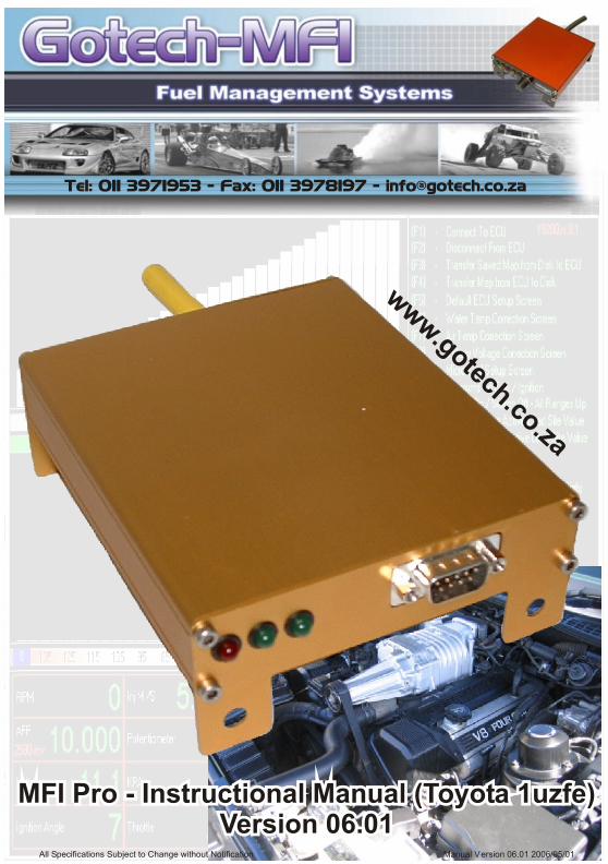
Index:
Introduction 1Before You Begin 1Basic Tools Required 2Basic Components Required 3Hardware Installation 3ECU Plug Pinout 16 Pin 4ECU Plug Pinout 12 Pin 5ECU Power Supply 6Fuel Injectors 7
Connecting The Fuel Injectors 8Ignition Output 9
Coil Charge Time 9Connecting The Coils 10
RPM Signal Input 11Connecting The RPM Input Signal 11Modifying the crank trigger plate 12
Throttle Position Sensor Input 13Water Temperature Sensor Input 14Air Temperature Sensor Input 14Lambda Sensor 15
Lambda Sensor Installation 15Closed Loop Lambda Control 15
Optional Output 16Connecting The Optional Output 16
Fuel Pump Output 16Connecting The Fuel Pump Output 16
Rev Counter Output 17
Fuel Management SystemFuel Management System
THE FUEL MANAGEMENT SPECIALISTSTHE FUEL MANAGEMENT SPECIALISTS
All Specifications Subject to Change without Notification Manual Version 06.01 2006/05/01
Page 1
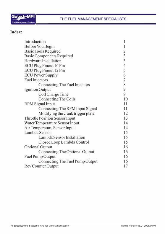
Introduction:
Congratulations on choosing a Gotech engine management system for your vehicle. Gotech MFI systems have been successfully installed on thousands of vehicles, from twin turbo v8’s, drag bikes to imported Japanese Toyotas. Over the past years many motor sport enthusiasts have discovered that the Gotech computer is easy to use and gets the job done correctly thus giving excellent reliability and enabling users to precisely control ignition timing and fuelling needs. Precise ignition and fuelling control leads to excellent drive ability and fuel economy.
Gotech MFI is suitable for most four stroke petrol engines from one to eight cylinders. MFI stands for Micro Fuel Injection. Don’t be fooled by the “micro” part of the name. Considering the features of this unit, it could just as well been named “Mighty Fuel Injection” The Gotech MFI ecu can be used on normally aspirated or charged vehicles boosting up to 1.5 bar boost (+ - 21psi). A 3 bar (+- 42psi) map sensor is available on request.
Before you begin:
1. Read the entire manual before starting, the greater you knowledge of the Gotech system, the easier you will find it to understand what you are doing, and why. Throughout the manual are warnings and notes that will help your installation run smoothly and indicate the known dangers that exist.2. Read any additional material accompanying this manual.3. You may need special parts, additional tools or test equipment in order to complete the installation. Make sure that you have all these items before you begin to avoid frustration.4. Don’t do the minimal work possible. Carelessness in the early stages of installation can cause major headaches later on. Carelessness will cost you money and frustration in finding and fixing unnecessary problems.5. Electromagnetic interference (EMI) from unsuppressed spark plug leads can cause the ecu to fail. Try keeping all signal wires as far away as possible from high EMI locations. Please use suppressed plug leads at all times. Never use copper or solid core plug leads.
Fuel Management SystemFuel Management System
THE FUEL MANAGEMENT SPECIALISTSTHE FUEL MANAGEMENT SPECIALISTS
All Specifications Subject to Change without Notification Manual Version 06.01 2006/05/01
Page 2
Before you begin continued:
6. In hot climates or with charged vehicles you might have to employ heat shielding to prevent heat soak to electrical and fuel parts. 7. We recommend you having your vehicle dynoed by professionals with the proper equipment.
Basic Tools Required For Wiring Installation:
Some basic tools are required for the Gotech wiring installation, these tools include:1. Side cutter2. Wire stripper3. Insulating tape4. Soldering iron5. Solder
Using heat shrink helps tidy up and insulate all the joints. A neat wiring harness makes fault finding easier and compliments the vehicle. Please use the Gotech wiring colour codes as far as possible.
Fuel Management SystemFuel Management System
THE FUEL MANAGEMENT SPECIALISTSTHE FUEL MANAGEMENT SPECIALISTS
WARNING - Before starting the Gotech installation:1. Avoid open sparks, flames or operation of electrical devices near flammable substances.2. Always disconnect the battery when doing electrical work on your vehicle.3. Do not charge the battery with a 24 volt truck charger or reverse the polarity of the battery or any charging unit.4. Do not charge the battery with the engine running as this could expose the ecu to an unregulated power supply that could destroy the ecu and other electrical equipment.5. All fuel system components and wiring should be mounted away from heat sources, shielded if necessary and well vented.6. Make sure that there are no leaks in the fuel system and that all connections are secure.7. Disconnect the Gotech ecu when doing any arc welding on the vehicle by unplugging the ecu from the main wiring harness.8. The engine should be earthed properly.
All Specifications Subject to Change without Notification Manual Version 06.01 2006/05/01
Page 3
You will need the following components fitted prior to the Gotech installation:
1. High pressure fuel pump capable of a continuos pressure of 3.5bar.2. Fuel pressure regulator3. Fuel injectors matched to the engine requirement.4. Throttle body with throttle position sensor. Throttle position sensor is only required on vehicles with high duration camshafts or normally aspirated race cars.5. Oil / Water temperature sender unit (Gotech calibrated preferred)6. A locked (no internal advance) electronic distributor setup or a crank trigger wheel / sensor combination.7. Good quality suppressed HT leads. Do not use solid core HT Leads.
The list above is basic and some extra parts will be required for the complete Gotech installation. Please consult with a experienced Gotech technician on if any other parts are required for the Gotech installation on your specific vehicle.
Hardware Installation:
Locate a convenient mounting position for the ecu. It is recommended that the ecu should be installed in the drivers compartment and shielded from any water or moisture.
Plug the harness into the ecu, and feed all wires except for the potentiometer through the firewall. A good seal around the wiring is necessary to prevent engine fumes from entering the cockpit and to protect the wiring.
Fuel Management SystemFuel Management System
THE FUEL MANAGEMENT SPECIALISTSTHE FUEL MANAGEMENT SPECIALISTS
NOTES:Installation of engine management systems is a complex exercise to be undertaken only after careful planning and research into the application for which the project is to be used Damage to engine components is a distinct possibility if care is not taken during the installation and setup of the Gotech engine management system. If you are unsure about how to wire any components of your engine, please consult and experiences installer for advice.
All Specifications Subject to Change without Notification Manual Version 06.01 2006/05/01
Page 4
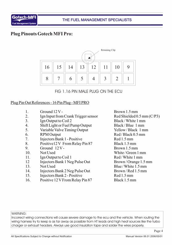
Plug Pinouts Gotech MFI Pro:
Plug Pin Out References - 16 Pin Plug - MFI PRO
1. Ground 12 V - Brown 1.5 mm2. Ign Input from Crank Trigger sensor Red Shielded 0.5 mm (C/P3)3. Ign Output to Coil 2 Black / White 1 mm4. Shift Light or Fuel Pump Output Black / Blue 1 mm5. Variable Valve Timing Output Yellow / Black 1 mm6. RPM Output Red / Black 0.5 mm7. Injectors Bank 1 - Positive Red 1.5 mm8. Positive12 V From Relay Pin 87 Black 1.5 mm9. Ground 12 V - Brown 1.5 mm10. Not Used White / Green 1 mm11. Ign Output to Coil 1 Red / White 1 mm12 Injectors Bank 1 Neg Pulse Out Brown / Orange 1.5 mm13. Not Used Blue / White 1.5 mm14. Injectors Bank 2 Neg Pulse Out Brown / Red 1.5 mm15. Injectors Bank 2 - Positive Red 1.5 mm16. Positive 12 V From Relay Pin 87 Black 1.5 mm
Fuel Management SystemFuel Management System
THE FUEL MANAGEMENT SPECIALISTSTHE FUEL MANAGEMENT SPECIALISTS
12345678
910111213141516
Retaining Clip
WARNING:Incorrect wiring connections will cause severe damage to the ecu and the vehicle. When routing the wiring harness try to keep is as far away as possible from HT leads and high heat sources like the turbo charger or exhaust headers. Always use good insulation tape and solder the wires properly.
FIG 1.16 PIN MALE PLUG ON THE ECU
All Specifications Subject to Change without Notification Manual Version 06.01 2006/05/01
Page 5
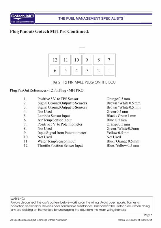
Plug Pinouts Gotech MFI Pro Continued:
Plug Pin Out References - 12 Pin Plug - MFI PRO
1. Positive 5 V to TPS Sensor Orange 0.5 mm2. Signal Ground Output to Sensors Brown / White 0.5 mm3. Signal Ground Output to Sensors Brown / White 0.5 mm4. Not Used Green 0.5 mm5. Lambda Sensor Input Black / Green 1 mm6. Air Temp Sensor Input Blue 0.5 mm7. Positive 5 V to Potentiometer Orange 0.5 mm8. Not Used Green / White 0.5mm9. Input Signal from Potentiometer Yellow 0.5 mm10. Not Used Not Used11. Water Temp Sensor Input Blue / Orange 0.5 mm12. Throttle Position Sensor Input Blue / Yellow 0.5 mm
Fuel Management SystemFuel Management System
THE FUEL MANAGEMENT SPECIALISTSTHE FUEL MANAGEMENT SPECIALISTS
123456
789101112
WARNING:Always disconnect the car’s battery before working on the wiring. Avoid open sparks, flames or operation of electrical devices near flammable substances. Disconnect the Gotech ecu when doing any arc welding on the vehicle by unplugging the ecu from the main wiring harness.
FIG 2. 12 PIN MALE PLUG ON THE ECU
All Specifications Subject to Change without Notification Manual Version 06.01 2006/05/01
Page 6
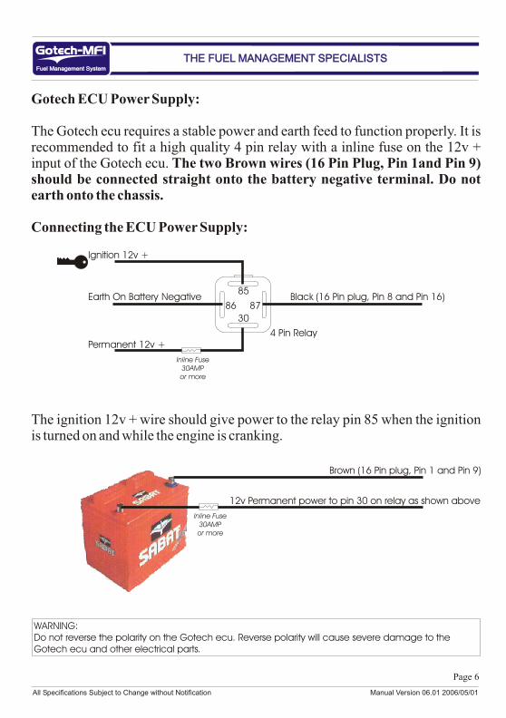
Gotech ECU Power Supply:
The Gotech ecu requires a stable power and earth feed to function properly. It is recommended to fit a high quality 4 pin relay with a inline fuse on the 12v + input of the Gotech ecu. The two Brown wires (16 Pin Plug, Pin 1and Pin 9) should be connected straight onto the battery negative terminal. Do not earth onto the chassis.
Connecting the ECU Power Supply:
The ignition 12v + wire should give power to the relay pin 85 when the ignition is turned on and while the engine is cranking.
Fuel Management SystemFuel Management System
THE FUEL MANAGEMENT SPECIALISTSTHE FUEL MANAGEMENT SPECIALISTS
Brown (16 Pin plug, Pin 1 and Pin 9)
Inline Fuse30AMPor more
12v Permanent power to pin 30 on relay as shown above
85
86
30
87Earth On Battery Negative
Ignition 12v +
Permanent 12v +
Black (16 Pin plug, Pin 8 and Pin 16)
4 Pin Relay
Inline Fuse30AMPor more
WARNING:Do not reverse the polarity on the Gotech ecu. Reverse polarity will cause severe damage to the Gotech ecu and other electrical parts.
All Specifications Subject to Change without Notification Manual Version 06.01 2006/05/01
Page 7
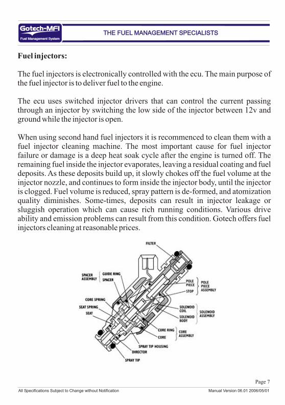
Fuel injectors:
The fuel injectors is electronically controlled with the ecu. The main purpose of the fuel injector is to deliver fuel to the engine.
The ecu uses switched injector drivers that can control the current passing through an injector by switching the low side of the injector between 12v and ground while the injector is open.
When using second hand fuel injectors it is recommenced to clean them with a fuel injector cleaning machine. The most important cause for fuel injector failure or damage is a deep heat soak cycle after the engine is turned off. The remaining fuel inside the injector evaporates, leaving a residual coating and fuel deposits. As these deposits build up, it slowly chokes off the fuel volume at the injector nozzle, and continues to form inside the injector body, until the injector is clogged. Fuel volume is reduced, spray pattern is de-formed, and atomization quality diminishes. Some-times, deposits can result in injector leakage or sluggish operation which can cause rich running conditions. Various drive ability and emission problems can result from this condition. Gotech offers fuel injectors cleaning at reasonable prices.
Fuel Management SystemFuel Management System
THE FUEL MANAGEMENT SPECIALISTSTHE FUEL MANAGEMENT SPECIALISTS

All Specifications Subject to Change without Notification Manual Version 06.01 2006/05/01
Page 8
Fuel injector Outputs:
The Gotech MFI Pro ecu offers two fuel injector outputs for the 1uzfe engine. These outputs are negative switching and can drive eight 12 ohm fuel injectors. The injector time is configurable up to 14ms (milliseconds).
Fuel Injector Connection:
Fuel Management SystemFuel Management System
THE FUEL MANAGEMENT SPECIALISTSTHE FUEL MANAGEMENT SPECIALISTS
12
34
12
34
Brow
n / Red
(16 Pin P
lug, Pin 1
4)
Red (16
Pin
Plug
, Pin 7)
Red (16
Pin
Plug
, Pin 15)
Brow
n / Oran
ge (1
6 Pin
Plug, P
in 12)
Front Pulley This Side
LLLEXUSLEXUS
All Specifications Subject to Change without Notification Manual Version 06.01 2006/05/01
Page 9
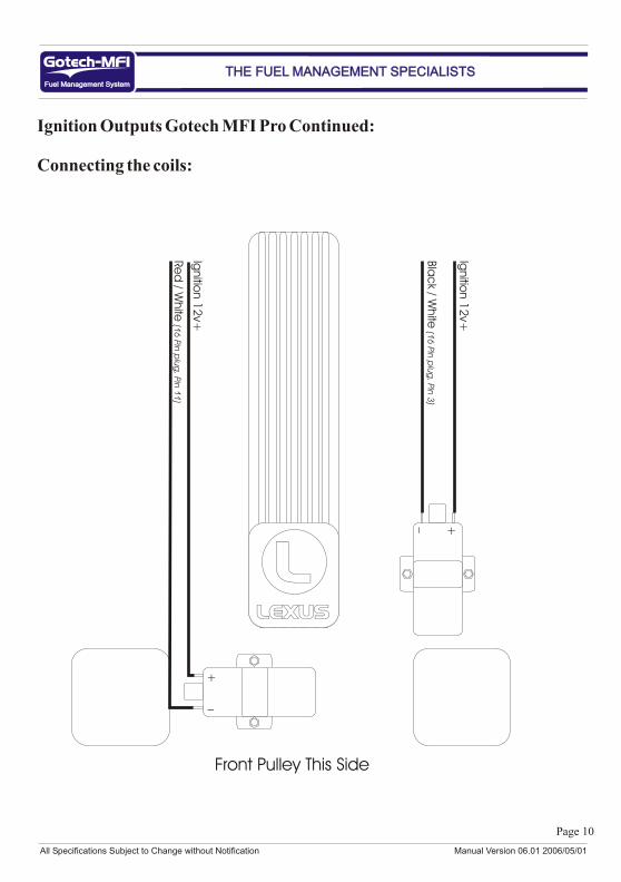
Ignition Outputs Gotech MFI Pro:
The ignition outputs on the Gotech MFI Pro ecu is used to trigger the coil(s). The coil(s) can be triggered directly from the ecu or external coil drivers can be used if preferred. The coil(s) should be negative triggering, a special ecu can be built for positive triggering coils on request. This system is capable of controlling either “intelligent” ignitors such as the popular Tp100 ignitor which has in-built dwell control or “dumb” ignitors which contain no such control. This allows standard ignitors to be used in many cases. Most standard ignitors are dumb ignitors. Take great care when setting up the Gotech main settings especially the internal / external features and coil charge time.
The two ignition outputs on the Gotech MFI Pro v8 ecu are:Black / White (16 Pin Plug, Pin 3)
Red / White (16 Pin Plug, Pin 11)
Coil charge time:
Coil charge time is the milli seconds (ms) that the coil or ignition module will be charged. This value is fully configurable through the Gotech dealer tune software. The recommended coil charge time is 2.00 ms. The coil charge time can be increased up to 4.00 ms. When running a higher coil charge time be sure to keep an eye on the ecu, ignition module and coil temperatures. If the coil charge time is too high or too low the engine will missfire or hesitate to rev up.
Fuel Management SystemFuel Management System
THE FUEL MANAGEMENT SPECIALISTSTHE FUEL MANAGEMENT SPECIALISTS
All Specifications Subject to Change without Notification Manual Version 06.01 2006/05/01
Page 10
Ignition Outputs Gotech MFI Pro Continued:
Connecting the coils:
Fuel Management SystemFuel Management System
THE FUEL MANAGEMENT SPECIALISTSTHE FUEL MANAGEMENT SPECIALISTS
+_
Ignitio
n 1
2v+
Bla
ck / W
hite
(16
Pin
plu
g, P
in 3
)
+
_
Ignitio
n 1
2v+
Re
d / W
hite
(16
Pin
plu
g, P
in 1
1)
Front Pulley This Side
LLLEXUSLEXUS
All Specifications Subject to Change without Notification Manual Version 06.01 2006/05/01
Page 11
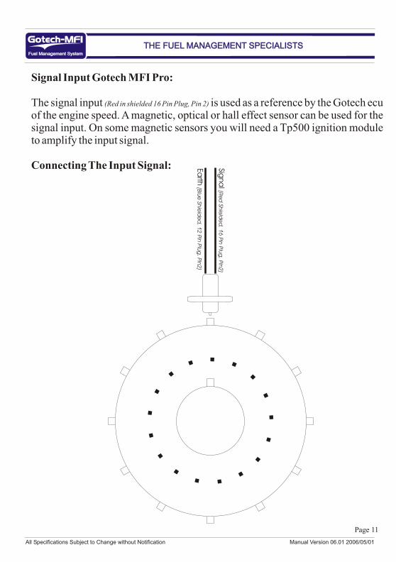
Signal Input Gotech MFI Pro:
The signal input (Red in shielded 16 Pin Plug, Pin 2) is used as a reference by the Gotech ecu of the engine speed. A magnetic, optical or hall effect sensor can be used for the signal input. On some magnetic sensors you will need a Tp500 ignition module to amplify the input signal.
Connecting The Input Signal:
Fuel Management SystemFuel Management System
THE FUEL MANAGEMENT SPECIALISTSTHE FUEL MANAGEMENT SPECIALISTS
Signa
l (Re
d Sh
ield
ed
, 16
Pin
Plu
g, P
in2
)
Ea
rth (B
lue
Shie
lde
d, 1
2 P
in P
lug
, Pin
2)
Remove this tooth
TDC
Direction of travel
All Specifications Subject to Change without Notification Manual Version 06.01 2006/05/01
Page 12
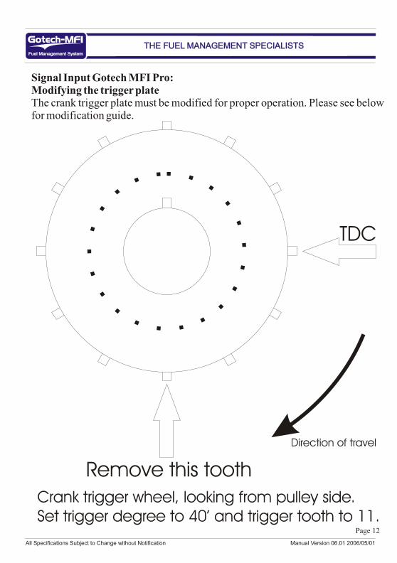
Signal Input Gotech MFI Pro:Modifying the trigger plateThe crank trigger plate must be modified for proper operation. Please see below for modification guide.
Fuel Management SystemFuel Management System
THE FUEL MANAGEMENT SPECIALISTSTHE FUEL MANAGEMENT SPECIALISTS
Crank trigger wheel, looking from pulley side.Set trigger degree to 40’ and trigger tooth to 11.
All Specifications Subject to Change without Notification Manual Version 06.01 2006/05/01
Page 13
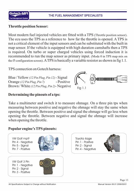
Throttle position Sensor:
Most modern fuel injected vehicles are fitted with a TPS (Throttle position sensor). The ecu uses the TPS as a reference to how far the throttle is opened. A TPS is not a critical element of the input sensors and can be substituted with the built in map sensor. If the vehicle is equipped with high duration camshafts then a TPS is required. On turbo or super charged vehicles using forced induction it is recommended to run the map sensor as primary input. (Mode 0 in TPS map mix on
the f5 configuration screen). A TPS is basically a variable resistor as shown in fig 1.1. TPS connection on Gotech harness:
Blue / Yellow (12 Pin Plug, Pin 12) - SignalOrange (12 Pin Plug, Pin 7) - PositiveBrown / White (12 Pin Plug, Pin 2)- Negative
Determining the pinouts of a tps:
Take a multimeter and switch it to measure ohmage. On a three pin tps when measuring between positive and negative the ohmage will stay the same when opening the throttle. Between positive and signal the ohmage will go less when opening the throttle. Between negative and signal the ohmage will increase when opening the throttle.
Popular engine’s TPS pinouts:
Fuel Management SystemFuel Management System
THE FUEL MANAGEMENT SPECIALISTSTHE FUEL MANAGEMENT SPECIALISTS
Toyota 4agePin 1 - PositivePin 2 - SignalPin 4 - Negative
1234
VW Golf 3 PinPin 1 - NegativePin 2 - SignalPin 3 - Positive
VW Golf mp9Pin 4 - NegativePin 5 - SignalPin 7 - Positive
+
-S
Fig 1.1
All Specifications Subject to Change without Notification Manual Version 06.01 2006/05/01
Page 14
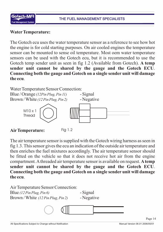
Water Temperature:
The Gotech ecu uses the water temperature sensor as a reference to see how hot the engine is for cold starting purposes. On air cooled engines the temperature sensor can be mounted to sense oil temperature. Most oem water temperature sensors can be used with the Gotech ecu, but it is recommended to use the Gotech temp sender unit as seen in fig 1.2 (Available from Gotech). A temp sender unit cannot be shared by the gauge and the Gotech ECU. Connecting both the gauge and Gotech on a single sender unit will damage the ecu.
Water Temperature Sensor Connection:Blue / Orange (12Pin Plug, Pin 11) - SignalBrown / White (12 Pin Plug, Pin 2) - Negative
Air Temperature:
The air temperature sensor is supplied with the Gotech wiring harness as seen in fig 1.3. This sensor gives the ecu an indication of the outside air temperature and then enriches the fuel mixtures accordingly. The air temperature sensor should be fitted on the vehicle so that it does not receive hot air from the engine compartment. A threaded air temperature sensor is available on request. A temp sender unit cannot be shared by the gauge and the Gotech ECU. Connecting both the gauge and Gotech on a single sender unit will damage the ecu.
Air Temperature Sensor Connection:Blue (12 Pin Plug, Pin 6) - SignalBrown / White (12 Pin Plug, Pin 2) - Negative
Fuel Management SystemFuel Management System
THE FUEL MANAGEMENT SPECIALISTSTHE FUEL MANAGEMENT SPECIALISTS
Fig 1.2
M10 x 1Thread
All Specifications Subject to Change without Notification Manual Version 06.01 2006/05/01
Page 15
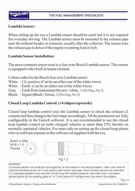
Lambda Sensor:
When setting up the ecu a Lambda sensor should be used, but it is not required for everyday driving. The Lambda sensor must be mounted in the exhaust pipe near the exhaust header or extractor, usually after the collector. The sensor uses the exhaust gas to detect if the engine is running lean or rich.
Lambda Sensor Installation:
The most common sensor used is a four wire Bosch Lambda sensor. This sensor is equipped with a built in heater element.
Colour codes for the Bosch four wire Lambda sensor:White - 12v positive (Can be on either one of the white wires)White - Earth (Can be on either one of the white wires)Gray - Earth from instrument (brown / white, 12 Pin Plug, Pin 2)Black - Signal (Black / Green, 12 Pin Plug, Pin 5)
Closed Loop Lambda Control: (v4 chipset upwards)
Closed loop lambda control uses the Lambda sensor to check the exhaust o2 content and then changes the fuel maps accordingly. All the parameters are fully configurable in the Gotech software. It is not recommended to use the closed loop lambda control on turbo charged vehicles or more than 25% throttle on normally aspirated vehicles. For more info on setting up the closed loop please refer to software manual on the software cd supplied with the ecu.
Fuel Management SystemFuel Management System
THE FUEL MANAGEMENT SPECIALISTSTHE FUEL MANAGEMENT SPECIALISTS
WARNING:A lambda sensor can easily be damaged by oil and debris in the exhaust system. Take care never to drop the lambda sensor as it may lead to permanent damage. Most Lambda sensors are intended for unleaded gasoline only and will not last long with leaded gasoline. Normally when a lambda sensor packs up the reading goes to 14.7 and does not change when you enrich the engine.
Bosch 4 WireM18 x 1.5Thread
Fig 1.3
All Specifications Subject to Change without Notification Manual Version 06.01 2006/05/01
Page 16
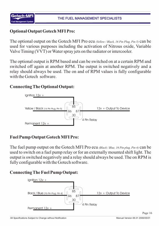
Optional Output Gotech MFI Pro:
The optional output on the Gotech MFI Pro ecu (Yellow / Black, 16 Pin Plug, Pin 5) can be used for various purposes including the activation of Nitrous oxide, Variable Valve Timing (VVT) or Water spray jets on the radiator or intercooler.
The optional output is RPM based and can be switched on at a certain RPM and switched off again at another RPM. The output is switched negatively and a relay should always be used. The on and of RPM values is fully configurable with the Gotech software.
Connecting The Optional Output:
Fuel Pump Output Gotech MFI Pro:
The fuel pump output on the Gotech MFI Pro ecu (Black / Blue, 16 Pin plug, Pin 4) can be used to switch on a fuel pump relay or for an externally mounted shift light. The output is switched negatively and a relay should always be used. The on RPM is fully configurable with the Gotech software.
Connecting The Fuel Pump Output:
Fuel Management SystemFuel Management System
THE FUEL MANAGEMENT SPECIALISTSTHE FUEL MANAGEMENT SPECIALISTS
85
86
30
87Yellow / Black (16 Pin Plug, Pin 5)
Ignition 12v +
Permanent 12v +
12v + Output To Device
4 Pin Relay
85
86
30
87Black / Blue (16 Pin Plug, Pin 4)
Ignition 12v +
Permanent 12v +
12v + Output To Device
4 Pin Relay
All Specifications Subject to Change without Notification Manual Version 06.01 2006/05/01
Page 17
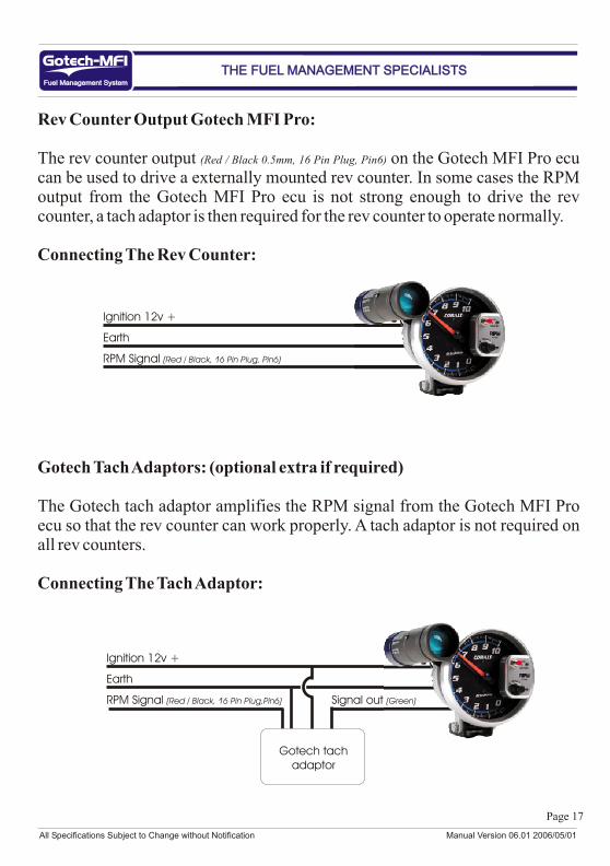
Rev Counter Output Gotech MFI Pro:
The rev counter output (Red / Black 0.5mm, 16 Pin Plug, Pin6) on the Gotech MFI Pro ecu can be used to drive a externally mounted rev counter. In some cases the RPM output from the Gotech MFI Pro ecu is not strong enough to drive the rev counter, a tach adaptor is then required for the rev counter to operate normally.
Connecting The Rev Counter:
Gotech Tach Adaptors: (optional extra if required)
The Gotech tach adaptor amplifies the RPM signal from the Gotech MFI Pro ecu so that the rev counter can work properly. A tach adaptor is not required on all rev counters.
Connecting The Tach Adaptor:
Fuel Management SystemFuel Management System
THE FUEL MANAGEMENT SPECIALISTSTHE FUEL MANAGEMENT SPECIALISTS
Ignition 12v +
Earth
RPM Signal (Red / Black, 16 Pin Plug, Pin6)
Ignition 12v +
Earth
RPM Signal (Red / Black, 16 Pin Plug,Pin6) Signal out (Green)
Gotech tachadaptor