Embed Size (px)
Citation preview
Articulate
d rob
ots
YA
Co
mp
act
sing
le-a
xis rob
ots
TRAN
SERVOS
ing
le-a
xis rob
ots
FLIP-X
Lin
ea
r mo
tor
sing
le-a
xis rob
ots
PHA
SER
Ca
rtesia
nro
bo
ts
XY-X
SC
AR
Aro
bo
ts
YK
-X
Pick &
pla
cero
bo
ts Y
P-XC
LEAN
CON
TROLLER
INFORM
ATION
Lin
ea
r convey o
r m
od
ule
s
LCM
100
218
MR
type
MF
type
Static loading moment
Controller
MF7/MF7D
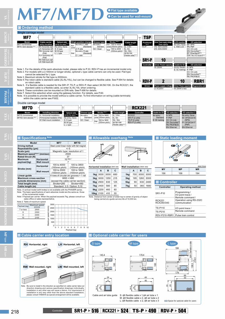
M type L typeS type
145.4
1524
1420. 5
100
5066
2935
170.4
100
4049
1420. 5
184
179
216.5
138.5
Space for optional cable for users
ϕ30:
Diam
eter
or r
oller
Cable and air tube guide S: ϕ8 flexible cable x 1,ϕ4 air tube x 1M: ϕ8 flexible cable x 2, ϕ6 air tube x 2L: ϕ8 flexible cable x 2, ϕ8 air tube x 3
LW
RH Horizontal, right
RW Wall mounted, right
LH Horizontal, left
Wall mounted, left
Be sure to install in the direction as specified (in cable carrier take-out direction drawing and various specification drawings) individually. Installation in any other way will cause a failure. For requirement of installation in any way other than the above standard installation, please consult YAMAHA as special arrangement will be available.
Note.
Controller Operating method
SR1-P10 Programming /I/O point trace /Remote command /Operation using RS-232C communication
RCX221RCX240/340
TS-P110 I/O point trace /Remote commandTS-P210
RDV-P210-RBR1 Pulse train control
M P
M R
M Y
(Unit: N·m)
MY MP MR
156 156 194
A
C
B C
BA
Horizontal installation (Unit: mm) Wall installation (Unit: mm)
A B C A B C
1kg 3000 3000 680 1kg 700 3000 3000
3kg 3000 1350 215 3kg 195 1260 3000
5kg 2900 830 125 5kg 90 630 2480
7kg 2400 580 85 7kg 50 360 1680
9kg 2200 460 60
10kg 2100 410 55
Note. Distance from center of slider top to center of gravity of object being carried at a guide service life of 10,000 km.
Model MF7 MF7DDriving method Steel cored linear motor with falt magnetRepeatability (μm) +/-5Scale (μm) Magnetic type: resolution of 1Maximum speed Note 2 (mm/sec) 2500Rated thrust (N) 37Maximum payload (kg)
Horizontal 10 Note 1
Wall mount 7
Stroke (mm)Horizontal
100 to 4000 (100mm pitch)
100 to 3800 (100mm pitch)
Wall mount100 to 2000
(100mm pitch)100 to 1800
(100mm pitch)Linear guide 4 rows of circular arc grooves × 1 railMaximum cross-section outside dimensions (mm)
W85 × H80 (except the cable carrier section)
Total length (mm) Stroke+280 Stroke+480Cable length (m) Standard: 3.5 / Option: 5,10
Note. A vertical model (with brake) is not available with the PHASER series.Note. The basic specifications of semi-absolute model are the same as those
of the incremental model.Note 1.Payload per carrier. When the payload exceeds 7kg, please consult our
sales office or sales representative.
Single carriage model
MF7Model Cable carrier
entry locationOptional cable
carrier for users Note 2Origin position change Grease type Stroke Note 3
Cable length
Note 4MF7: IncrementalHori-zontal
No entry: L side (Standard)
No entry: Standard
Hori-zontal
100 to 4000(100mm pitch)MF7A: Semi-absolute Note 1 RH: Horizontal, right No entry: None 3L: 3.5m
LH: Horizontal, left S: S type Z: R side GC: CleanWall 100 to 2000
(100mm pitch)5L: 5m
FRH: Horizontal, right (Flat)
M: M typeWall
No entry: R side (Standard)
10L: 10mL: L type 3K/5K/10K
(Flexible cable)Note 5FLH: Horizontal, left (Flat)
Z: L side
RW: Wall mount, rightLW: Wall mount, left
Double carriage model
MF7D RCX221Model Installing direction Optional cable
carrier for users Note 2
Grease type Stroke Note 3 Cable length Controller Usable for CE I/O selection 1 I/O selection 2
MF7D: Incremental H: Horizontal installation No entry: Standard
Hori-zontal
100 to 3800(100mm pitch)
3L: 3.5m RCX221 No entry: Standard
N: NPN No entry: NoneMF7AD: Semi-absolute Note 1 FH:Horizontal installation (Flat) No entry: None 5L: 5m SR1-P (2 units) P: PNP N1: OP.DIO24/16
(NPN)W: Wall mount installation S: S type GC: CleanWall 100 to 1800
(100mm pitch)10L: 10m TS-P (2 units) E: CE marking CC: CC-Link
M: M type 3K/5K/10K(Flexible cable)Note 5
RDV-P (2 units) DN: DeviceNetTM P1: OP.DIO24/17 (PNP)L: L type PB: PROFIBUS
EN: Ethernet EN: Ethernet
Note 2. Table of maximum speed
Payload (kg) Maximum speed (mm/s)
7 or less 2500
8 2300
9 2200
10 2100
0 1 2 3 4 5 6 7 8 9 10
3000
2500
2000
1500
1000
500
0
Payload (kg)
Max
imum
spe
ed (
mm
/s)
TSPPositioner
Note 6
Driver: Power-supply voltage /Power capacity
LCD monitor I/O selectionNo entry: None NP: NPN
TS-P 110: 100V/200W L: With LCD PN: PNP210: 200V/200W CC: CC-Link
DN: DeviceNetTM
EP: EtherNet/IPTM
GW: No I/O board Note 7
SR1-P 10Controller Driver: Power capacity Usable for CE I/O selection
10: 200W No entry: Standard N: NPNE: CE marking P: PNP
CC: CC-LinkDN: DeviceNetTM
PB: PROFIBUS
Controller SR1-P u 516 RCX221 u 524 TS-P u 490 RDV-P u 504
Note 1. For the details of the semi-absolute model, please refer to P.33. RDV-P has an incremental model only.Note 2. For models with a 2,100mm or longer stroke, optional L type cable carriers can only be used. Flat type
cannot be selected for L type.Note 3. Maximum stroke for flat type is 2000mm.Note 4.The robot cable is standard cable (3L/5L/10L), but can be changed to flexible cable. See P.594 for details
on robot cable.Note 5. If a flexible cable is needed for the SR1-P, TS-P, or RDV-P, then select 3K/5K/10K. On the RCX221, the
standard cable is a flexible cable, so enter 3L/5L/10L when ordering.Note 6. These controllers can be mounted on DIN rails. See P.498 for details.Note 7. Select this selection when using the gateway function. For details, see P.60.Note. It is possible to provide the model without a cable carrier. To find information on wiring (cable terminals)
within the cable carrier see P.602.
Flat type available ●
Can be used for wall-mount ●
RDV-P 2 10 RBR1Driver Power-supply voltage Driver: Power capacity Regenerative unit
2: AC200V 10: 200W or less
Ordering method
Specifications Note Allowable overhang Note
Cable carrier entry location Optional cable carrier for users
Articulate
d rob
ots
YA
Co
mp
act
sing
le-a
xis rob
ots
TRAN
SERVOS
ing
le-a
xis rob
ots
FLIP-X
Lin
ea
r mo
tor
sing
le-a
xis rob
ots
PHA
SER
Ca
rtesia
nro
bo
ts
XY-X
SC
AR
Aro
bo
ts
YK
-X
Pick &
pla
cero
bo
ts YP-X
CLEA
NCO
NTRO
LLERINFO
RMATIO
N
Lin
ea
r convey o
r m
od
ule
s
LCM
100
219
MR
type
MF
type
MF7/MF7D
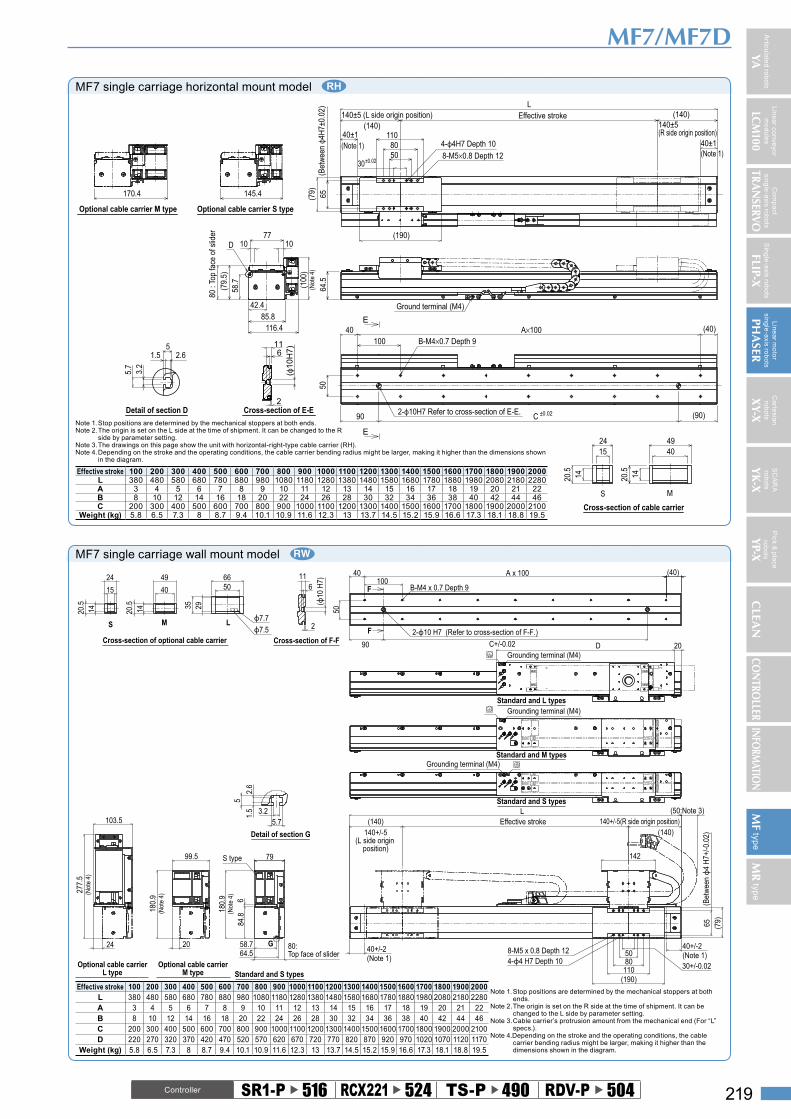
MF7 single carriage horizontal mount model
S
Cross-section of cable carrier
M
49
20.5
40
14
15
20.5
14
24
Detail of section D
3.2
5.7
1.5 2.65
Optional cable carrier S typeOptional cable carrier M type80
: To
p fa
ce o
f slid
er 7710
(79.
5)
10
42.4(1
00)
(Not
e 4)
58.7
D
116.485.8
145.4170.4
90 C ±0.02 (90)
10040 A×100 (40)
50
B-M4×0.7 Depth 9
2-ф10H7 Refer to cross-section of E-E.
Ground terminal (M4)
64.5
30±0.025080
65(79)
140±5 (L side origin position) (140)
LEffective stroke
4-ф4H7 Depth 10
8-M5×0.8 Depth 12
(190)
11040±1(Note 1)
(140)140±5 (R side origin position)
40±1(Note 1)
(Bet
wee
n ф4
H7±
0.02
)E
E
( ф10
H7)6
11
2Cross-section of E-E
Note 1. Stop positions are determined by the mechanical stoppers at both ends.Note 2. The origin is set on the L side at the time of shipment. It can be changed to the R
side by parameter setting.Note 3. The drawings on this page show the unit with horizontal-right-type cable carrier (RH).Note 4. Depending on the stroke and the operating conditions, the cable carrier bending radius might be larger, making it higher than the dimensions shown
in the diagram.
Effective stroke 100 200 300 400 500 600 700 800 900 1000 1100 1200 1300 1400 1500 1600 1700 1800 1900 2000L 380 480 580 680 780 880 980 1080 1180 1280 1380 1480 1580 1680 1780 1880 1980 2080 2180 2280A 3 4 5 6 7 8 9 10 11 12 13 14 15 16 17 18 19 20 21 22B 8 10 12 14 16 18 20 22 24 26 28 30 32 34 36 38 40 42 44 46C 200 300 400 500 600 700 800 900 1000 1100 1200 1300 1400 1500 1600 1700 1800 1900 2000 2100
Weight (kg) 5.8 6.5 7.3 8 8.7 9.4 10.1 10.9 11.6 12.3 13 13.7 14.5 15.2 15.9 16.6 17.3 18.1 18.8 19.5
Controller SR1-P u 516 RCX221 u 524 TS-P u 490 RDV-P u 504
MF7 single carriage wall mount model
5080
(190)
65 (79)
142
L
110
(50:Note 3)(140) Effective stroke
(140)140+/-5(L side origin
position)
58.764.5
84.8
6
180.
9(N
ote
4)
79
G
S type
Standard and S types
20
180.
9(N
ote
4)
99.5
Optional cable carrierM type
24
103.5
277.
5(N
ote
4)
Optional cable carrierL type
Standard and S types
Grounding terminal (M4)Standard and M types
Grounding terminal (M4)Standard and L types
Grounding terminal (M4)
10040 (40)
50
90 C+/-0.02
F
F
116
2
Cross-section of F-F
3.25.7
1.5
2.6
5
Detail of section G
6650
2935
20.5
14
40
49
15
24
1420.5
Cross-section of optional cable carrier
LMSϕ7.7
ϕ7.5
(ϕ10
H7)
B-M4 x 0.7 Depth 9
A x 100
2-ϕ10 H7 (Refer to cross-section of F-F.)
140+/-5(R side origin position)
(Bet
wee
n ϕ4
H7+
/-0.0
2)
30+/-0.02
40+/-2(Note 1)
8-M5 x 0.8 Depth 124-ϕ4 H7 Depth 10
40+/-2(Note 1)
80:Top face of slider
D 20
Effective stroke 100 200 300 400 500 600 700 800 900 1000 1100 1200 1300 1400 1500 1600 1700 1800 1900 2000Note 1. Stop positions are determined by the mechanical stoppers at both
ends.Note 2. The origin is set on the R side at the time of shipment. It can be
changed to the L side by parameter setting.Note 3. Cable carrier’s protrusion amount from the mechanical end (For “L”
specs.).Note 4.Depending on the stroke and the operating conditions, the cable
carrier bending radius might be larger, making it higher than the dimensions shown in the diagram.
L 380 480 580 680 780 880 980 1080 1180 1280 1380 1480 1580 1680 1780 1880 1980 2080 2180 2280A 3 4 5 6 7 8 9 10 11 12 13 14 15 16 17 18 19 20 21 22B 8 10 12 14 16 18 20 22 24 26 28 30 32 34 36 38 40 42 44 46C 200 300 400 500 600 700 800 900 1000 1100 1200 1300 1400 1500 1600 1700 1800 1900 2000 2100D 220 270 320 370 420 470 520 570 620 670 720 770 820 870 920 970 1020 1070 1120 1170
Weight (kg) 5.8 6.5 7.3 8 8.7 9.4 10.1 10.9 11.6 12.3 13 13.7 14.5 15.2 15.9 16.6 17.3 18.1 18.8 19.5
Articulate
d rob
ots
YA
Co
mp
act
sing
le-a
xis rob
ots
TRAN
SERVOS
ing
le-a
xis rob
ots
FLIP-X
Lin
ea
r mo
tor
sing
le-a
xis rob
ots
PHA
SER
Ca
rtesia
nro
bo
ts
XY-X
SC
AR
Aro
bo
ts
YK
-X
Pick &
pla
cero
bo
ts Y
P-XC
LEAN
CON
TROLLER
INFORM
ATION
Lin
ea
r convey o
r m
od
ule
s
LCM
100
220
MR
type
MF
type
Controller SR1-P u 516 RCX221 u 524 TS-P u 490 RDV-P u 504
MF7/MF7D
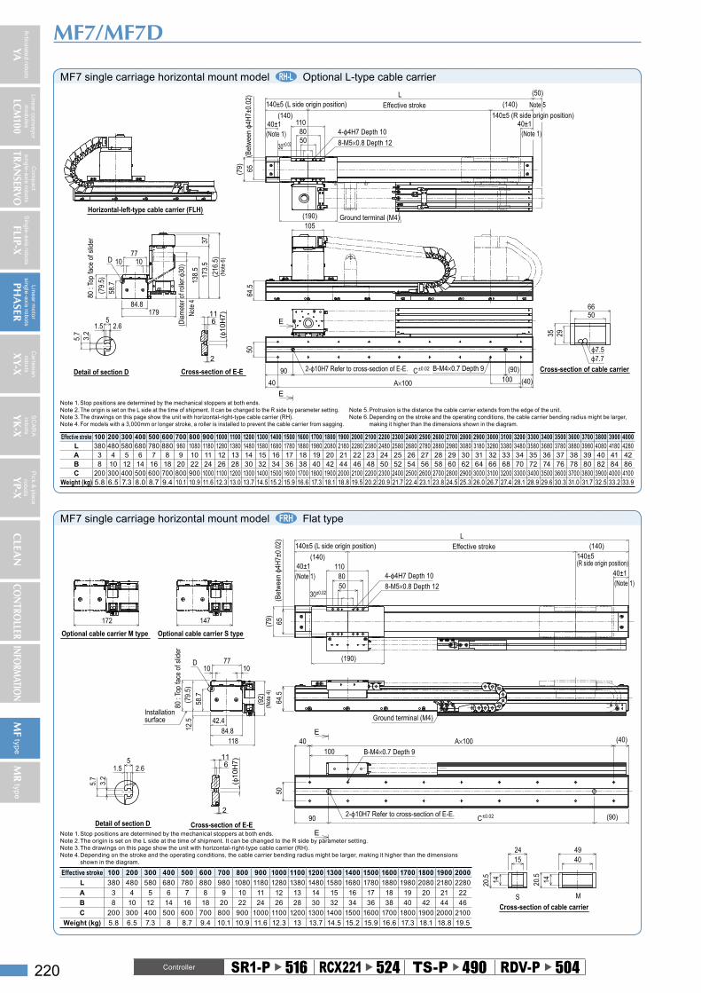
MF7 single carriage horizontal mount model Optional L-type cable carrier
Horizontal-left-type cable carrier (FLH)
80 :
Top
face
of s
lider
10
(79.
5)
10
58.7
D
84.8
173.
537
(216
.5)
(Not
e 6)
77
138.
5
(Dia
met
er o
f rol
ler:ф
30)
Note
4
179
Cross-section of cable carrier
6650
35 29
ф7.7ф7.5
Detail of section D
3.2
5.7
1.5 2.65
90 C±0.02 (90)10040 A×100 (40)
50
B-M4×0.7 Depth 92-ф10H7 Refer to cross-section of E-E.
64.5
105Ground terminal (M4)
30±0.025080
65(79)
140±5 (L side origin position)
(140)
L
Effective stroke (140)
140±5 (R side origin position)
4-ф4H7 Depth 10
8-M5×0.8 Depth 12
(190)
110
(50)
Note 5
40±1(Note 1)
40±1(Note 1)
(Bet
wee
n ф4
H7±
0.02
)
E
E
(ф10
H7)
2
611
Cross-section of E-E
Effective stroke 100 200 300 400 500 600 700 800 900 1000 1100 1200 1300 1400 1500 1600 1700 1800 1900 2000 2100 2200 2300 2400 2500 2600 2700 2800 2900 3000 3100 3200 3300 3400 3500 3600 3700 3800 3900 4000L 380 480 580 680 780 880 980 1080 1180 1280 1380 1480 1580 1680 1780 1880 1980 2080 2180 2280 2380 2480 2580 2680 2780 2880 2980 3080 3180 3280 3380 3480 3580 3680 3780 3880 3980 4080 4180 4280A 3 4 5 6 7 8 9 10 11 12 13 14 15 16 17 18 19 20 21 22 23 24 25 26 27 28 29 30 31 32 33 34 35 36 37 38 39 40 41 42B 8 10 12 14 16 18 20 22 24 26 28 30 32 34 36 38 40 42 44 46 48 50 52 54 56 58 60 62 64 66 68 70 72 74 76 78 80 82 84 86C 200 300 400 500 600 700 800 900 1000 1100 1200 1300 1400 1500 1600 1700 1800 1900 2000 2100 2200 2300 2400 2500 2600 2700 2800 2900 3000 3100 3200 3300 3400 3500 3600 3700 3800 3900 4000 4100
Weight (kg) 5.8 6.5 7.3 8.0 8.7 9.4 10.1 10.9 11.6 12.3 13.0 13.7 14.5 15.2 15.9 16.6 17.3 18.1 18.8 19.5 20.2 20.9 21.7 22.4 23.1 23.8 24.5 25.3 26.0 26.7 27.4 28.1 28.9 29.6 30.3 31.0 31.7 32.5 33.2 33.9
Note 1. Stop positions are determined by the mechanical stoppers at both ends.Note 2. The origin is set on the L side at the time of shipment. It can be changed to the R side by parameter setting.Note 3. The drawings on this page show the unit with horizontal-right-type cable carrier (RH).Note 4. For models with a 3,000mm or longer stroke, a roller is installed to prevent the cable carrier from sagging.
Note 5. Protrusion is the distance the cable carrier extends from the edge of the unit.Note 6. Depending on the stroke and the operating conditions, the cable carrier bending radius might be larger,
making it higher than the dimensions shown in the diagram.
MF7 single carriage horizontal mount model Flat type
Optional cable carrier S typeOptional cable carrier M type
80 :
Top
face
of s
lider
7710
(79.
5)
10
58.7
D
11884.812
.5
(92)
(Not
e 4)
Installation surface
172 147
42.4
30±0.025080
65(79)
140±5 (L side origin position)
(140)
LEffective stroke (140)
140±5 (R side origin position)
4-ф4H7 Depth 10
8-M5×0.8 Depth 12
(190)
11040±1(Note 1) 40±1
(Note 1)
(Bet
wee
n ф4
H7±
0.02
)
Ground terminal (M4)
64.5
90 C±0.02 (90)
10040 A×100 (40)
50
B-M4×0.7 Depth 9
2-ф10H7 Refer to cross-section of E-E.
SCross-section of cable carrier
M
49
20.5
40
14
15
20.5 14
24
Detail of section D
3.2
5.7
1.5 2.65
Cross-section of E-E
E
E
6
( ф10
H7)
11
2
Note 1. Stop positions are determined by the mechanical stoppers at both ends.Note 2. The origin is set on the L side at the time of shipment. It can be changed to the R side by parameter setting.Note 3. The drawings on this page show the unit with horizontal-right-type cable carrier (RH).Note 4. Depending on the stroke and the operating conditions, the cable carrier bending radius might be larger, making it higher than the dimensions
shown in the diagram.
Effective stroke 100 200 300 400 500 600 700 800 900 1000 1100 1200 1300 1400 1500 1600 1700 1800 1900 2000
L 380 480 580 680 780 880 980 1080 1180 1280 1380 1480 1580 1680 1780 1880 1980 2080 2180 2280
A 3 4 5 6 7 8 9 10 11 12 13 14 15 16 17 18 19 20 21 22
B 8 10 12 14 16 18 20 22 24 26 28 30 32 34 36 38 40 42 44 46
C 200 300 400 500 600 700 800 900 1000 1100 1200 1300 1400 1500 1600 1700 1800 1900 2000 2100
Weight (kg) 5.8 6.5 7.3 8 8.7 9.4 10.1 10.9 11.6 12.3 13 13.7 14.5 15.2 15.9 16.6 17.3 18.1 18.8 19.5

Articulate
d rob
ots
YA
Co
mp
act
sing
le-a
xis rob
ots
TRAN
SERVOS
ing
le-a
xis rob
ots
FLIP-X
Lin
ea
r mo
tor
sing
le-a
xis rob
ots
PHA
SER
Ca
rtesia
nro
bo
ts
XY-X
SC
AR
Aro
bo
ts
YK
-X
Pick &
pla
cero
bo
ts YP-X
CLEA
NCO
NTRO
LLERINFO
RMATIO
N
Lin
ea
r convey o
r m
od
ule
s
LCM
100
221
MR
type
MF
type
Controller SR1-P u 516 RCX221 u 524 TS-P u 490 RDV-P u 504
MF7/MF7D
MF7D double carriage horizontal mount model
Optional cable carrier S typeOptional cable carrier M type80
: To
p fa
ce o
f slid
er 7710
(79.
5)
10
42.4(1
00)
(Not
e 3)
58.7
D
116.485.8
145.4170.4
30±0.025080
65(79)
140±5 (Note 1)L
Effective stroke140±5 (Note 1)
4-ф4H7 Depth 10
8-M5×0.8 Depth 12
(190)
11040±1
(Note 2)
40±1(Note 2)
Effective stroke (200 : Minimum distance between carriages)
(Bet
wee
n ф4
H7±
0.02
)Ground terminal (M4)
64.5
90 C±0.02 (90)
10040 A×100 (40)
50
B-M4×0.7 Depth 9
2-ф10H7 Refer to cross-section of E-E.
S
Cross-section of cable carrier
M
49
20.5
40
14
15
20.5
14
24
Detail of section D
3.2
5.7
1.5 2.65
E
E
(ф10
H7)6
11
2
Cross-section of E-E
Note 1. Position of the table slider when returned to the origin.Note 2. Stop positions are determined by the mechanical stoppers at both ends.Note 3. Depending on the stroke and the operating conditions, the cable carrier bending radius might be larger, making it higher than the dimensions shown
in the diagram.
Effective stroke 100 200 300 400 500 600 700 800 900 1000 1100 1200 1300 1400 1500 1600 1700 1800 1900 2000L 580 680 780 880 980 1080 1180 1280 1380 1480 1580 1680 1780 1880 1980 2080 2180 2280 2380 2480A 5 6 7 8 9 10 11 12 13 14 15 16 17 18 19 20 21 22 23 24B 12 14 16 18 20 22 24 26 28 30 32 34 36 38 40 42 44 46 48 50C 400 500 600 700 800 900 1000 1100 1200 1300 1400 1500 1600 1700 1800 1900 2000 2100 2200 2300
Weight (kg) 9.3 10.2 11.1 12.0 12.9 13.9 14.8 15.7 16.6 17.5 18.5 19.4 20.3 21.2 22.1 23.1 24.0 24.9 25.8 26.7
MF7D double carriage wall mount model
(190)
8050
65 (79)
5080
(190)110110
(79) 65
142142
L (50:Note 2)(50:Note 2)
Effective stroke
Effective stroke
Standard and S types
Standard and M types
Standard and L types
40100
A x 100 (40)
50
90
F
F2
611
6650
2935
20.5
14
40
49
15
24
1420.5
58.764.5
84.8
6
180.
9(N
ote
3)
79
G
S type
Standard and S types
3.2
5.7
1.5
2.6
5
Detail of section G
20
180.
9(N
ote
3)
99.5
Optional cable carrierM type
24
103.5
277.
5(N
ote
3)
Optional cable carrierL type
LMS
Cross-section of F-FCross-section of optional cable carrier
ϕ7.7ϕ7.5
(ϕ10
H7)
B-M4 x 0.7 Depth 9
2-ϕ10 H7 (Refer to cross-section of F-F.)
C+/-0.02
140+/-5 140+/-5(200 : Minimum distance between carriages)
(Bet
wee
n ϕ4
H7+
/-0.0
2)
(Bet
wee
n ϕ4
H7+
/-0.0
2)
40+/-2(Note 1)
30+/-0.02
8-M5 x 0.8 Depth 124-ϕ4 H7 Depth 10
8-M5 x 0.8 Depth 124-ϕ4 H7 Depth 10
40+/-2(Note 1)
30+/-0.02
80:Top face of slider
Grounding terminal (M4)
Grounding terminal (M4)
D 2020 DGrounding terminal (M4)
Effective stroke 100 200 300 400 500 600 700 800 900 1000 1100 1200 1300 1400 1500 1600 1700 1800L 580 680 780 880 980 1080 1180 1280 1380 1480 1580 1680 1780 1880 1980 2080 2180 2280A 5 6 7 8 9 10 11 12 13 14 15 16 17 18 19 20 21 22B 12 14 16 18 20 22 24 26 28 30 32 34 36 38 40 42 44 46C 400 500 600 700 800 900 1000 1100 1200 1300 1400 1500 1600 1700 1800 1900 2000 2100D 220 270 320 370 420 470 520 570 620 670 720 770 820 870 920 970 1020 1070
Weight (kg) 9.3 10.2 11.1 12.0 12.9 13.9 14.8 15.7 16.6 17.5 18.5 19.4 20.3 21.2 22.1 23.1 24.0 24.9
Note 1. Stop positions are determined by the mechanical stoppers at both ends.
Note 2. Cable carrier’s protrusion amount from the mechanical end.Note 3. Depending on the stroke and the operating conditions, the cable
carrier bending radius might be larger, making it higher than the dimensions shown in the diagram.

Articulate
d rob
ots
YA
Co
mp
act
sing
le-a
xis rob
ots
TRAN
SERVOS
ing
le-a
xis rob
ots
FLIP-X
Lin
ea
r mo
tor
sing
le-a
xis rob
ots
PHA
SER
Ca
rtesia
nro
bo
ts
XY-X
SC
AR
Aro
bo
ts
YK
-X
Pick &
pla
cero
bo
ts Y
P-XC
LEAN
CON
TROLLER
INFORM
ATION
Lin
ea
r convey o
r m
od
ule
s
LCM
100
222
MR
type
MF
type
MF7D double carriage horizontal mount model Flat type
E
E
Optional cable carrier S typeOptional cable carrier M type
80 :
Top
face
of s
lider
7710
(79.
5)
10
58.7
D
11884.812
.5
(92)
(Not
e 3)
Installation surface
172 147
42.4
30±0.025080
65(79)
L
4-ф4H7 Depth 10
8-M5×0.8 Depth 12
(190)
11040±1(Note 1)
40±1(Note 1)
Effective stroke140±5 (Note 1)
Effective stroke
140±5 (Note 1)(200 : Minimum distance between carriages)
(Bet
wee
n ф4
H7±
0.02
)
Ground terminal (M4)
64.5
Ground terminal (M4)
90 C±0.02 (90)
100
40 A×100 (40)
50
B-M4×0.7 Depth 9
2-ф10H7 Refer to cross-section of E-E.
S
Cross-section of cable carrier
M
49
20.5
40
14
15
20.5
14
24
Detail of section D
3.2
5.7
1.5 2.65
Cross-section of E-E
(ф10
H7)611
2
Note 1. Position of the table slider when returned to the origin.Note 2. Stop positions are determined by the mechanical stoppers at both ends.Note 3. Depending on the stroke and the operating conditions, the cable carrier bending radius might be larger, making it higher than the dimensions shown
in the diagram.
Effective stroke 100 200 300 400 500 600 700 800 900 1000 1100 1200 1300 1400 1500 1600 1700 1800 1900 2000L 580 680 780 880 980 1080 1180 1280 1380 1480 1580 1680 1780 1880 1980 2080 2180 2280 2380 2480A 5 6 7 8 9 10 11 12 13 14 15 16 17 18 19 20 21 22 23 24B 12 14 16 18 20 22 24 26 28 30 32 34 36 38 40 42 44 46 48 50C 400 500 600 700 800 900 1000 1100 1200 1300 1400 1500 1600 1700 1800 1900 2000 2100 2200 2300
Weight (kg) 9.3 10.2 11.1 12.0 12.9 13.9 14.8 15.7 16.6 17.5 18.5 19.4 20.3 21.2 22.1 23.1 24.0 24.9 25.8 26.7
MF7D double carriage horizontal mount model Optional L-type cable carrier
90 C±0.02 (90)
10040 A×100 (40)
50
B-M4×0.7 Depth 92-ф10H7 Refer to cross-section of E-E.
(Bet
wee
n ф4
H7±
0.02
)64
.5
105Ground terminal (M4)Ground terminal (M4)
30±0.02 5080
65(79)
L
4-ф4H7 Depth 108-M5×0.8 Depth 12
(190)
11040±1(Note 2)
40±1(Note 2)
Effective stroke140±5 (Note 1)
Effective stroke
140±5 (Note 1)(200 : Minimum distance between carriages)
(50)
Note 4
(50)
Note 4
E
E
80 :
Top
face
of s
lider
10
(79.
5)
10
58.7
D
84.8
173.
537
(216
.5)
(Not
e 5)
77
138.
5
(Dia
met
er o
f rol
ler:ф
30)
Note
3
179
Cross-section of cable carrier
6650
35 29
ф7.7ф7.5
Detail of section D
3.2
5.7
1.5 2.65
Cross-section of E-E
6
(ф10
H7)11
2
Effective stroke 100 200 300 400 500 600 700 800 900 1000 1100 1200 1300 1400 1500 1600 1700 1800 1900 2000 2100 2200 2300 2400 2500 2600 2700 2800 2900 3000 3100 3200 3300 3400 3500 3600 3700 3800L 580 680 780 880 980 1080 1180 1280 1380 1480 1580 1680 1780 1880 1980 2080 2180 2280 2380 2480 2580 2680 2780 2880 2980 3080 3180 3280 3380 3480 3580 3680 3780 3880 3980 4080 4180 4280A 5 6 7 8 9 10 11 12 13 14 15 16 17 18 19 20 21 22 23 24 25 26 27 28 29 30 31 32 33 34 35 36 37 38 39 40 41 42B 12 14 16 18 20 22 24 26 28 30 32 34 36 38 40 42 44 46 48 50 52 54 56 58 60 62 64 66 68 70 72 74 76 78 80 82 84 86C 400 500 600 700 800 900 1000 1100 1200 1300 1400 1500 1600 1700 1800 1900 2000 2100 2200 2300 2400 2500 2600 2700 2800 2900 3000 3100 3200 3300 3400 3500 3600 3700 3800 3900 4000 4100
Weight (kg) 9.3 10.2 11.1 12.0 12.9 13.9 14.8 15.7 16.6 17.5 18.5 19.4 20.3 21.2 22.1 23.1 24.0 24.9 25.8 26.7 27.7 28.6 29.5 30.4 31.3 32.3 33.2 34.1 35.0 35.9 36.9 37.8 38.7 39.6 40.5 41.5 42.4 43.3
Note 1. Position of the table slider when returned to the origin.Note 2. Stop positions are determined by the mechanical stoppers at both ends.Note 3. For models with a 3,000mm or longer stroke, a roller is installed to prevent the cable carrier from sagging.Note 4. Protrusion is the distance the cable carrier extends from the edge of the unit.Note 5. Depending on the stroke and the operating conditions, the cable carrier bending radius might be larger, making it higher than the dimensions shown in the diagram.
Controller SR1-P u 516 RCX221 u 524 TS-P u 490 RDV-P u 504
MF7/MF7D


![Acai [aˌsaˈi] How to prepare it? 1kg of acai pulp – 1kg miąższu acai 1 banana 400ml of gurana syrup – 400 ml syropu guarany Confetti Granola - musli](https://img.pdfslide.us/doc/110x75/5515639155034685568b5c04/acai-asai-how-to-prepare-it-1kg-of-acai-pulp-1kg-miazszu-acai-1-banana-400ml-of-gurana-syrup-400-ml-syropu-guarany-confetti-granola-musli.jpg)