Embed Size (px)
Citation preview
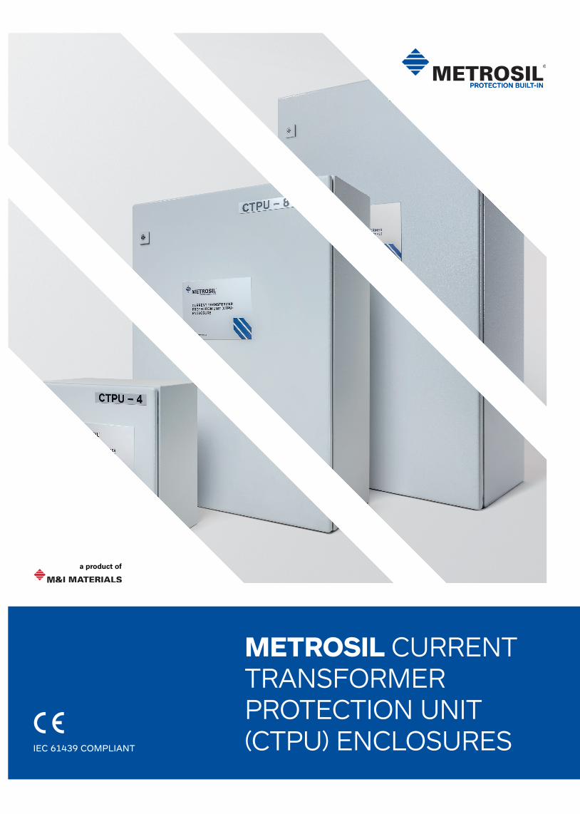
METROSIL CURRENT TRANSFORMER PROTECTION UNIT (CTPU) ENCLOSURESIEC 61439 COMPLIANT
Current transformer open circuit protection with reliability, flexibility and expertise built-in.
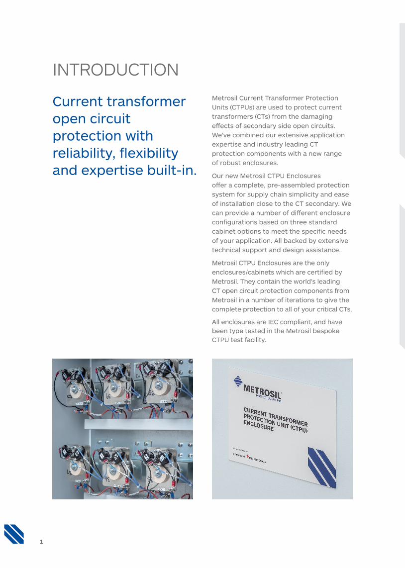
Metrosil Current Transformer Protection Units (CTPUs) are used to protect current transformers (CTs) from the damaging effects of secondary side open circuits. We’ve combined our extensive application expertise and industry leading CT protection components with a new range of robust enclosures.
Our new Metrosil CTPU Enclosures offer a complete, pre-assembled protection system for supply chain simplicity and ease of installation close to the CT secondary. We can provide a number of different enclosure configurations based on three standard cabinet options to meet the specific needs of your application. All backed by extensive technical support and design assistance.
Metrosil CTPU Enclosures are the only enclosures/cabinets which are certified by Metrosil. They contain the world’s leading CT open circuit protection components from Metrosil in a number of iterations to give the complete protection to all of your critical CTs.
All enclosures are IEC compliant, and have been type tested in the Metrosil bespoke CTPU test facility.
INTRODUCTION
1
METROSIL CTPU ENCLOSURE BENEFITS:
• Type tested and independently certified to IEC 61439 Parts 1&2
• Flexible fitting options for either a flat wall or pole mounting to suit site requirements
• Adaptable configurations depending on the arrangement of the CT protection systems
• Single supplier for CTPU components and enclosures to reduce supply chain complexity
METROSIL CTPU ENCLOSURE FEATURES:
• Three standard cabinet sizes
• IP 66 rated
• Removable gland plate
• Sealed fasteners
• Fitted with integral basic protection barrier
• CE approved
• Direct connection and ease of installation close to the CT secondary
• Multiple SCADA signal wiring configurations
Three standard enclosures have been selected to house the different numbers of CTPUs. The terminal layouts of the enclosures are detailed in the Wiring section.
The Metrosil CTPU enclosure series are offered in the following configurations.
TABLE 1: ENCLOSURE OPTIONS
Enclosure option
Number of CTPUs
in the enclosure
CTPU type (Type
A, B, C, 3166, 3140, 3134)
Enclosure size
(WxHxD) (mm)
Loaded weight
(kg) - take number from the
next chart
International Protection
Marking
Impact rating
Nema class
Manufactured in accordance
with IEC 61439
Metrosil Enclosure CTPU - 3
3 All W:380 H:380 D:210
9.8
IP66IK08
1.7Kg / 5 joules
4 Yes
Metrosil Enclosure CTPU - 4
4 All W:380 H:380 D:210
14
Metrosil Enclosure CTPU - 6
6 All W:600 H:800 D:250
33.6
Metrosil Enclosure CTPU - 8
8 All W:600 H:800 D:250
44.5
Metrosil Enclosure CTPU - 9
9 All W:600 H:1000 D:250
50.5
Metrosil Enclosure CTPU - 12
12 All W:600 H:1000 D:250
67
ENCLOSURES
3
Item Enclosure mounting type Enclosure mountings Load rating M&I part No.
1Wall mount 1500N / 150Kg / distributed over 4
brackets, symmetrical loadingFME / WALL MOUNT / ENCLOSURE
2Pole mount 1000N / 100Kg / distributed over 2
brackets, symmetrical loadingFME / POLE MOUNT / ENCLOSURE
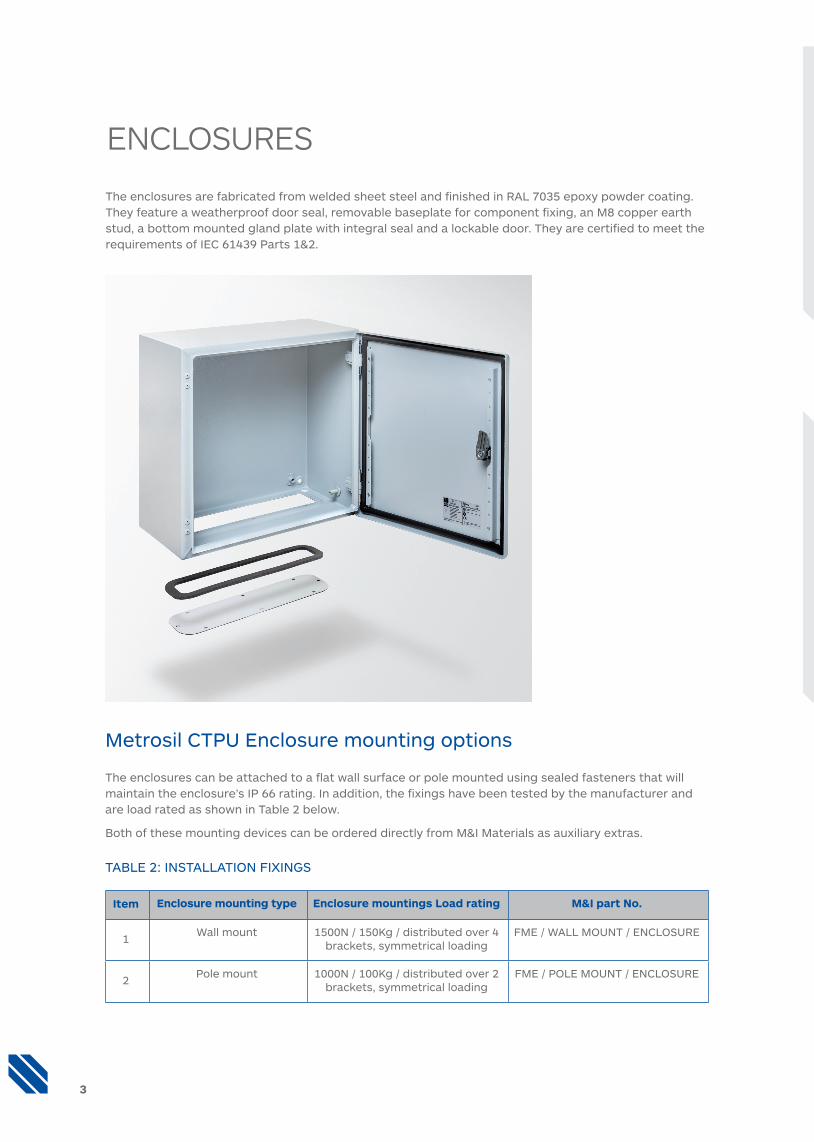
The enclosures are fabricated from welded sheet steel and finished in RAL 7035 epoxy powder coating. They feature a weatherproof door seal, removable baseplate for component fixing, an M8 copper earth stud, a bottom mounted gland plate with integral seal and a lockable door. They are certified to meet the requirements of IEC 61439 Parts 1&2.
Metrosil CTPU Enclosure mounting options
The enclosures can be attached to a flat wall surface or pole mounted using sealed fasteners that will maintain the enclosure’s IP 66 rating. In addition, the fixings have been tested by the manufacturer and are load rated as shown in Table 2 below.
Both of these mounting devices can be ordered directly from M&I Materials as auxiliary extras.
TABLE 2: INSTALLATION FIXINGS
CTPU GROUPINGS
Size Product name CTPU per enclosure
CTPU groupings
Comments
1
Metrosil Enclosure CTPU-3
3 1 x 3ph Open Circuit protection of one x 3-phase set of CTs
Metrosil Enclosure CTPU-4
4 1 x (3ph + 1N) Open Circuit protection of one x 3-phase & neutral set of CTs
2
Metrosil Enclosure CTPU-6
6 2 x 3ph Open Circuit protection of two x 3-phase set of CTs
Metrosil Enclosure CTPU-8
8 2 x (3ph + 2N) Open Circuit protection of two x 3-phase & neutral set of CTs
3
Metrosil Enclosure CTPU-9
9 3 x 3ph Open Circuit protection of three x 3-phase set of CTs
Metrosil Enclosure CTPU-12
12 4 x 3ph Open Circuit protection of three x 3-phase & neutral set of CTs
Metrosil Enclosure CTPU-12
12 3 x (3ph + 3N) Open Circuit protection of four x 3-phase set of CTs
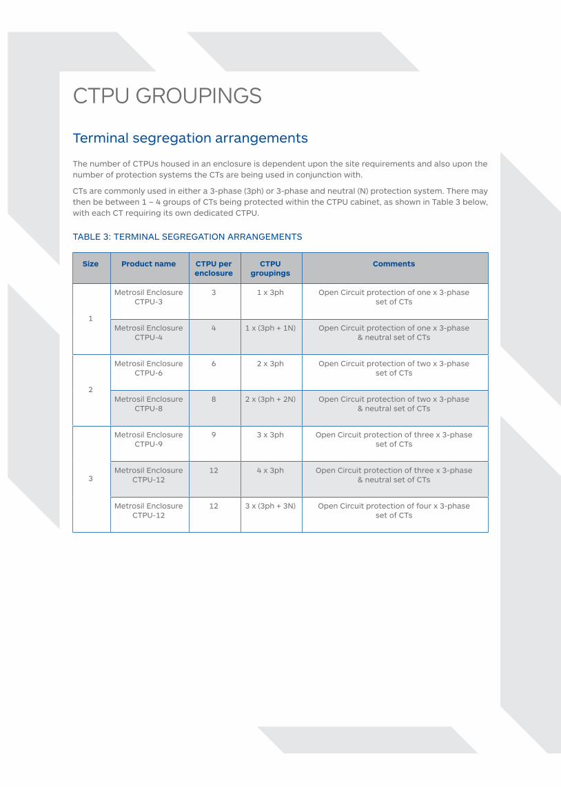
Terminal segregation arrangements
The number of CTPUs housed in an enclosure is dependent upon the site requirements and also upon the number of protection systems the CTs are being used in conjunction with.
CTs are commonly used in either a 3-phase (3ph) or 3-phase and neutral (N) protection system. There may then be between 1 – 4 groups of CTs being protected within the CTPU cabinet, as shown in Table 3 below, with each CT requiring its own dedicated CTPU.
TABLE 3: TERMINAL SEGREGATION ARRANGEMENTS
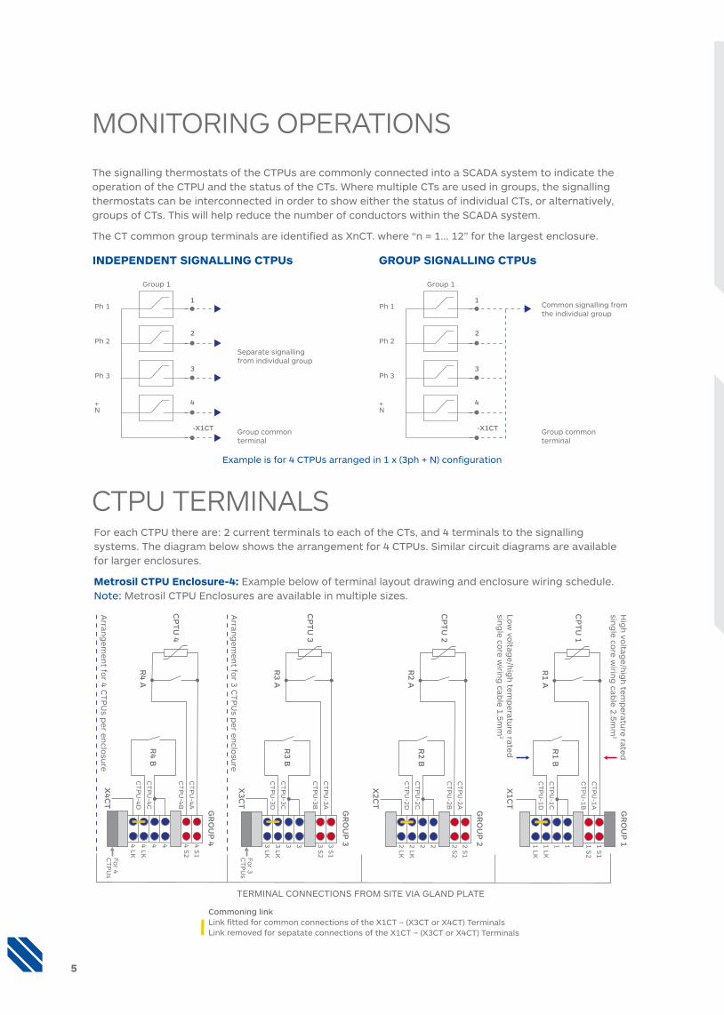
The signalling thermostats of the CTPUs are commonly connected into a SCADA system to indicate the operation of the CTPU and the status of the CTs. Where multiple CTs are used in groups, the signalling thermostats can be interconnected in order to show either the status of individual CTs, or alternatively, groups of CTs. This will help reduce the number of conductors within the SCADA system.
The CT common group terminals are identified as XnCT. where “n = 1... 12” for the largest enclosure.
Example is for 4 CTPUs arranged in 1 x (3ph + N) configuration
MONITORING OPERATIONS
CTPU TERMINALS
Group commonterminal
Separate signallingfrom individual group
-X1CT
4
3
2
1Ph 1
Ph 2
Ph 3
+N
Group 1
Group commonterminal
Common signalling fromthe individual group
-X1CT
4
3
2
1Ph 1
Ph 2
Ph 3
+N
Group 1
Group commonterminal
Separate signallingfrom individual group
-X1CT
4
3
2
1Ph 1
Ph 2
Ph 3
+N
Group 1
Group commonterminal
Common signalling fromthe individual group
-X1CT
4
3
2
1Ph 1
Ph 2
Ph 3
+N
Group 1
INDEPENDENT SIGNALLING CTPUs GROUP SIGNALLING CTPUs
5
For each CTPU there are: 2 current terminals to each of the CTs, and 4 terminals to the signalling systems. The diagram below shows the arrangement for 4 CTPUs. Similar circuit diagrams are available for larger enclosures.
Metrosil CTPU Enclosure-4: Example below of terminal layout drawing and enclosure wiring schedule. Note: Metrosil CTPU Enclosures are available in multiple sizes.
TERMINAL CONNECTIONS FROM SITE VIA GLAND PLATE
GR
OU
P 1
Hig
h vo
ltage/h
igh
temp
erature rated
sing
le core w
iring
cable 2.5m
m2
Low
voltag
e/hig
h tem
peratu
re ratedsin
gle co
re wirin
g cab
le 1.5mm
2
Arran
gem
ent fo
r 4 CT
PU
s per en
closu
re
X1C
T
R1 B
R1 A
CP
TU
1
1 S1
1 S2
1 1 1 LK
1 LKC
TP
U-1D
CT
PU
-1C
CT
PU
-1B
CT
PU
-1A
X2C
T
R2 B
R2 A
CP
TU
2
2 S1
2 S2
2 2 2 LK
2 LKC
TP
U-2D
CT
PU
-2C
CT
PU
-2B
CT
PU
-2A
X3C
T
R3 B
R3 A
CP
TU
3
3 S1
3 S2
3 3 3 LK
3 LKC
TP
U-3D
CT
PU
-3C
CT
PU
-3B
CT
PU
-3A
X4C
T
R4 B
R4 A
CP
TU
4
4 S1
4 S2
4 4 4 LK
4 LKC
TP
U-4D
CT
PU
-4C
CT
PU
-4B
CT
PU
-4A
GR
OU
P 2
GR
OU
P 3
GR
OU
P 4
For 4
CT
PU
s
For 3
CT
PU
sA
rrang
emen
t for 3 C
TP
Us p
er enclo
sure
Commoning linkLink fitted for common connections of the X1CT – (X3CT or X4CT) TerminalsLink removed for sepatate connections of the X1CT – (X3CT or X4CT) Terminals
COMPLIANCEIEC 61439 All Metrosil CTPU Enclosures are designed and manufactured according to IEC 61439 Parts 1&2: 2009. Full details of the testing undertaken to achieve this can be supplied upon request.
CE – all enclosures are CE certified (under directive 2014/35/EU – low voltage directive). Proof of certification is available on request.
Metrosil Approved Metrosil CTPU enclosures are the only enclosures/cabinets which are manufactured and approved by Metrosil. Every single cabinet will have to pass through our world renowned QC procedure before being signed off by a qualified member of our quality inspection team. Only then will each cabinet be given the badge of assurance.
ISO 9001:2008 M&I Materials, the parent company of Metrosil, is certified to ISO 9001 standards.
ISO 14001 M&I Materials Ltd, manufacturer of specialist materials for industry and science, has achieved certification by Lloyd’s Register Quality Assurance under the Environment Management Standard ISO 14001.
MANUFACTURER: M&I Materials Ltd, Hibernia Way, Trafford park, Manchester, M32 0ZD, UK.
EQUIPMENT DESIGNATION: CTPUs in Enclosures.
ENVIRONMENTAL: Ambient temperature (5oC to 45oC).
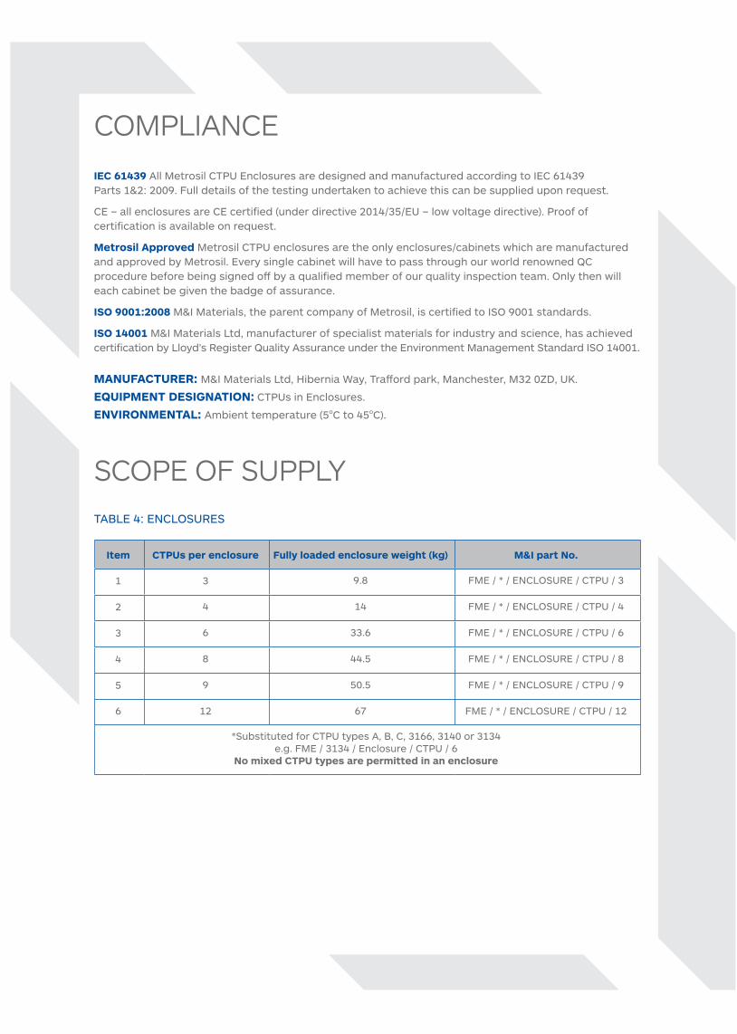
SCOPE OF SUPPLYTABLE 4: ENCLOSURES
Item CTPUs per enclosure Fully loaded enclosure weight (kg) M&I part No.
1 3 9.8 FME / * / ENCLOSURE / CTPU / 3
2 4 14 FME / * / ENCLOSURE / CTPU / 4
3 6 33.6 FME / * / ENCLOSURE / CTPU / 6
4 8 44.5 FME / * / ENCLOSURE / CTPU / 8
5 9 50.5 FME / * / ENCLOSURE / CTPU / 9
6 12 67 FME / * / ENCLOSURE / CTPU / 12
*Substituted for CTPU types A, B, C, 3166, 3140 or 3134e.g. FME / 3134 / Enclosure / CTPU / 6
No mixed CTPU types are permitted in an enclosure

HANDLING, INSTALLATION & MAINTENANCE INSTRUCTIONSThe following instructions are to be followed for the safe handling, installation and operation of the
designated series of equipment.
INSTALLATION INSTRUCTIONS
1 Observe safe lifting and handling practices since the enclosures exceed the safe manual handling capacity of 25kg per person.
2 Ensure the equipment is undamaged and that all door fittings, gland plates, fasteners and seals are intact before installing.
3 Ensure that the installation location can safely handle the weight of the equipment before attempting installation.
4 Only the recommended installation fixings of four per enclosure attached at the designated locations on the rear of the enclosure shall be used.
5 The equipment shall be installed in a location that does not exceed the IP 66 rating of the cabinet.
6 Keep away from sources of direct heat (locally radiated and solar).
7 Ensure adequate clearance is provided for the circulation of air around the equipment.
8 Only use glands that are IP 66 rated and sized according to the cable selection for the end user application.
9 Remove the gland plate when making entries into the enclosure to avoid contaminating the equipment.
10 Ensure that all wire terminations into the enclosure are installed following recognised good standards of workmanship.
11 Follow local site working instructions as necessary for the safe installation and use of the equipment.
12 Ensure that all power is removed before attempting any electrical installation work and that the supply is locked off. Follow local site working instructions as necessary.
MAINTENANCE INSTRUCTIONS
1 There are no user serviceable components within the equipment.
2 Periodic visual inspection of the equipment is recommended to ensure the equipment is undamaged and that all door locks and seals are intact.
3 If damage is observed cease using the equipment and report the problem to your local authorised representative or directly to M&I Materials Ltd.
Any recommendation or suggestion relating to the use, storage, handling or properties of the products supplied by M&I Materials Ltd or any member of its group, either in sales and technical literature or in response to a specific enquiry or otherwise, is given in good faith but it is for the customer to satisfy itself of the suitability of the product for its own particular purposes and to ensure that the product is used correctly and safely in accordance with the manufacturer’s written instructions. © M&I Materials Ltd 2018.
ENQUIRIESTel: +44 (0)161 864 5456e-mail: [email protected]
metrosil.com
Contact the Metrosil team for further technical details about our range of CTPU Enclosures:


![Current Transformer[1]](https://img.pdfslide.us/doc/110x75/577ca5521a28abea748b7c14/current-transformer1.jpg)