Embed Size (px)
Citation preview
Metronome Command Reference Rev 05/01 Elmo Motion Controlhttp://www.elmomc.com
- 1 -
Metronome Motion Controller for ELMO
Digital Products: “SAXOPHONE, CLARINET”
Command Reference
Revision 05/01

Metronome Command Reference Rev 05/01 Elmo Motion Controlhttp://www.elmomc.com
- 2 -
Previews Revisions:
Revision Description
11/00 Modified Commands: • AG – gains are changed according to unit mode (UM). • AN – more elements added. • CA – tacho definition. • CL – motor not moving definition. • HL – changes in restrictions. • MS – position stabilized report. • VH/VL – change in ranges.
New Commands:
• RI – reset input. • TG – gain for tacho feedback • TR – in target position.
05/01 Modified Commands: • EM – on the fly change for first valid index. • SF – smooth factor for position mode.
New Commands:
• FL – fault logic setting • YA – auxiliary array parameters.
Metronome Command Reference Rev 05/01 Elmo Motion Controlhttp://www.elmomc.com
- 3 -
Table of Contents:
1 INTRODUCTION.............................................................................................................................................11
1.1 Scope..........................................................................................................................................................................12
1.2 Notations and Conventions......................................................................................................................................12
1.3 Command References ..............................................................................................................................................12
2 TASK-BASED REFERENCE .........................................................................................................................13
2.1 Task Descriptions .....................................................................................................................................................13
2.2 Task-Based Commands List ....................................................................................................................................14
2.3 Alphabetical Commands Reference........................................................................................................................20
3 ALPHABETICAL COMMANDS REFERENCE ..............................................................................................22
3.1 ## and #@ - Label Name..........................................................................................................................................22
3.2 #@AUTO_ - Automatic Routine .............................................................................................................................23
3.3 ** - Comment............................................................................................................................................................25
3.4 AC – Acceleration.....................................................................................................................................................26
3.5 AF – Wait Until (After)............................................................................................................................................27
3.6 AG[N] - Analog Gain Array ....................................................................................................................................28
3.7 AM - Analog Mode ...................................................................................................................................................31
3.8 AN[N] - Analog Inputs Array..................................................................................................................................32
3.9 AO - Analog Output .................................................................................................................................................34
3.10 AS[N] - Analog Inputs Offsets Array .....................................................................................................................35
3.11 BG - Begin Motion....................................................................................................................................................36
3.12 BH – Get a Single Signal as Hexadecimal ..............................................................................................................37
3.13 BI - Begin On Input..................................................................................................................................................39
3.14 BM – Begin mask......................................................................................................................................................40
3.15 CA – Commutation Array .......................................................................................................................................41
3.16 CC – Compile Program............................................................................................................................................44
3.17 CD – CPU dump .......................................................................................................................................................47
3.18 CL[N] - Current Continuous Limitations and Motor Not Moving Protection Parameters...............................48
Metronome Command Reference Rev 05/01 Elmo Motion Controlhttp://www.elmomc.com
- 4 -
3.19 CP - Clear Program................................................................................................................................................. 50
3.20 CS - Code Status....................................................................................................................................................... 51
3.21 DC – Deceleration .................................................................................................................................................... 52
3.22 DL - Download Program ......................................................................................................................................... 53
3.23 DV[N] - Reference Desired Value ........................................................................................................................... 54
3.24 EC – Error Code ...................................................................................................................................................... 55
3.25 EF[N] - Encoder Filter Frequency.......................................................................................................................... 62
3.26 EM[N] – ECAM Parameters................................................................................................................................... 64
3.27 EN - End Program Execution ................................................................................................................................. 65
3.28 EO - Echo Mode....................................................................................................................................................... 66
3.29 ER[N] - Maximum Tracking Error........................................................................................................................ 67
3.30 ET[N] – Entries for ECAM Table .......................................................................................................................... 68
3.31 FA - Floating Point Accuracy ................................................................................................................................. 69
3.32 FF – Feed Forward .................................................................................................................................................. 70
3.33 FL – Fault Logic....................................................................................................................................................... 71
3.34 FR – Follower Ratio................................................................................................................................................. 72
3.35 GS[N] – Gain Scheduling ........................................................................................................................................ 73
3.36 HL[N] – Over speed limit and position range limit............................................................................................... 75
3.37 HM[N] – Homing and Capture Mode .................................................................................................................... 77
3.38 HP - Halt Program Execution................................................................................................................................. 79
3.39 HX - Hexadecimal Mode ......................................................................................................................................... 80
3.40 HY[N] – Auxiliary Homing and Capture Mode.................................................................................................... 81
3.41 IA[N] - Integer Array .............................................................................................................................................. 84
3.42 IB[N] - Input Bits Array.......................................................................................................................................... 85
3.43 ID,IQ – Read the Active current and the Reactive current (SAX Only)............................................................ 86
3.44 IL[N] – Input logic ................................................................................................................................................... 87
3.45 IM – Motor current (Clarinet only) ....................................................................................................................... 93
3.46 IP - Input Port .......................................................................................................................................................... 94
3.47 JP - Jump (Conditionally) ....................................................................................................................................... 95

Metronome Command Reference Rev 05/01 Elmo Motion Controlhttp://www.elmomc.com
- 5 -
3.48 JS - Jump (Call) To Subroutine ..............................................................................................................................96
3.49 JV - Jogging Velocity ...............................................................................................................................................97
3.50 JZ - Jump And Zero Stack ......................................................................................................................................98
3.51 KD[N], KI[N], KP[N] - PI Parameters ...................................................................................................................99
3.52 KF[N] - Advanced Filter For Position/Dual Loop ...............................................................................................100
3.53 KL - Kill Motion And Program.............................................................................................................................101
3.54 KV[N] - Advanced Filter For Speed Loop ...........................................................................................................102
3.55 LC - Current Limit Flag ........................................................................................................................................103
3.56 LD - Load Parameters From FLASH...................................................................................................................104
3.57 LG - Load User Program.......................................................................................................................................105
3.58 LL[N] - Low Actual Feedback Limit ....................................................................................................................106
3.59 LP - List Properties ................................................................................................................................................107
3.60 LS - List User Program..........................................................................................................................................108
3.61 MC – Maximum Peak Driver Current .................................................................................................................109
3.62 MF - Motor Failure ................................................................................................................................................110
3.63 MG – Send Message ...............................................................................................................................................113
3.64 MI – Mask Interrupt ..............................................................................................................................................114
3.65 MO - Motor Enable/Disable ..................................................................................................................................116
3.66 MP[N] Motion Parameters (PT/PVT Parameters)..............................................................................................118
3.67 MS - Motion Status.................................................................................................................................................120
3.68 MZ – Uploading Message ......................................................................................................................................122
3.69 OB[N] - Output Bits Array....................................................................................................................................123
3.70 OP - Output Port ....................................................................................................................................................124
3.71 OS - Analog Output Full Scale ..............................................................................................................................125
3.72 PA – Position Absolute...........................................................................................................................................126
3.73 PE – Position Error ................................................................................................................................................128
3.74 PL[N] - Peak Duration And Limit ........................................................................................................................129
3.75 PM – Profiler Mode................................................................................................................................................132
3.76 PP[N] – Protocol Parameters.................................................................................................................................133

Metronome Command Reference Rev 05/01 Elmo Motion Controlhttp://www.elmomc.com
- 6 -
3.77 PR – Relative Position............................................................................................................................................ 137
3.78 PS - Program Status............................................................................................................................................... 138
3.79 PT – Position Time Command (++)...................................................................................................................... 139
3.80 PV – Position Velocity Time Command (++)....................................................................................................... 140
3.81 PX- Main Positions ................................................................................................................................................ 141
3.82 PY - Auxiliary Position .......................................................................................................................................... 142
3.83 QP[N], QT[N], QV[N] – Position, Time, Velocity ............................................................................................... 143
3.84 RA[N] - Real Array................................................................................................................................................ 144
3.85 RC – Define recorded variables ............................................................................................................................ 145
3.86 RG – Recorder gap ................................................................................................................................................ 147
3.87 RI – Reset input...................................................................................................................................................... 148
3.88 RL – Recorder length ............................................................................................................................................ 149
3.89 RM - Reference Mode............................................................................................................................................ 150
3.90 RP[N] – Recorder parameters .............................................................................................................................. 153
3.91 RR – Activate recorder / Get recorder status...................................................................................................... 158
3.92 RS - Soft Reset........................................................................................................................................................ 159
3.93 RT – Return............................................................................................................................................................ 160
3.94 SA – Stepper Angle ................................................................................................................................................ 161
3.95 SC - Single Command............................................................................................................................................ 162
3.96 SD – Stop Deceleration .......................................................................................................................................... 163
3.97 SF - Smooth Factor ................................................................................................................................................ 164
3.98 SG - Save User Program........................................................................................................................................ 166
3.99 SI – Stop On Input ................................................................................................................................................. 167
3.100 SM - Stop Mask...................................................................................................................................................... 168
3.101 SP – Speed for PTP mode...................................................................................................................................... 169
3.102 SR - Status Register ............................................................................................................................................... 171
3.103 ST - Stop Motion .................................................................................................................................................... 173
3.104 SV - Save Parameters To Flash............................................................................................................................. 174
3.105 TC - Torque Command ......................................................................................................................................... 175

Metronome Command Reference Rev 05/01 Elmo Motion Controlhttp://www.elmomc.com
- 7 -
3.106 TG - Analog Gain For Tacho Feedback (Clarinet only) .....................................................................................176
3.107 TR – Target Radius ................................................................................................................................................178
3.108 TS – Sampling time ................................................................................................................................................180
3.109 UM – Unit mode .....................................................................................................................................................181
3.110 VE - Velocity Error ................................................................................................................................................183
3.111 VH[H],VL[N] – High and low Reference Limit ...................................................................................................184
3.112 VR - Firmware Version..........................................................................................................................................186
3.113 VX - Velocity Of Main Feedback ..........................................................................................................................187
3.114 VY - Velocity Of Auxiliary Feedback ...................................................................................................................188
3.115 WI[N] – Extended state, Integer ...........................................................................................................................189
3.116 WS[N] – Extended state, Floating point ...............................................................................................................190
3.117 WT – Wait...............................................................................................................................................................192
3.118 XC, XQ - Execute or Continue Program..............................................................................................................193
3.119 XM – X Modulo ......................................................................................................................................................195
3.120 YD - Auxiliary Counts Direction...........................................................................................................................196
3.121 YM – Y Modulo ......................................................................................................................................................197

Metronome Command Reference Rev 05/01 Elmo Motion Controlhttp://www.elmomc.com
- 8 -
Table of Figures:
Figure 1 - Torque reference generation model ......................................................................................................150 Figure 2 - Speed reference generation model........................................................................................................151 Figure 3 - Position reference generation model ....................................................................................................152 Figure 4 - Slope and window trigger types ...........................................................................................................153 Figure 5 – Pre trigger delay...................................................................................................................................155 Figure 6 - Smooth Factor model............................................................................................................................165 Figure 7 - Speed model .........................................................................................................................................169 Figure 8 – VH and VL settings .............................................................................................................................185

Metronome Command Reference Rev 05/01 Elmo Motion Controlhttp://www.elmomc.com
- 9 -
List of Tables:
Table 1: Motion Commands....................................................................................................................................14 Table 2: I/O Commands ..........................................................................................................................................15 Table 3: Status Commands ......................................................................................................................................15 Table 4: Feedback Commands ................................................................................................................................16 Table 5: Configuration Commands .........................................................................................................................16 Table 6: Communication Commands ......................................................................................................................17 Table 7: Control Filter Command ...........................................................................................................................17 Table 8: Protections Commands..............................................................................................................................17 Table 9: Data Recording Commands.......................................................................................................................18 Table 10: User Program Commands .......................................................................................................................19 Table 11: General Commands .................................................................................................................................19 Table 12: Automatic Subroutines ............................................................................................................................23 Table 13: Analog gains – Analog Input #1..............................................................................................................28 Table 14: Analog gains – Analog Input #2..............................................................................................................28 Table 15: BH – record structure ..............................................................................................................................38 Table 16: BM – Begin mask....................................................................................................................................40 Table 17: The CA vector – The parameters related to digital Hall sensors.............................................................41 Table 18: The CA vector – The parameters related to resolver setup .....................................................................41 Table 19: The CA vector – The parameters related to encoder setup......................................................................42 Table 20: The CA vector – The parameters related to commutation setup .............................................................42 Table 21: The CA vector – The parameters related to automatic commutation search...........................................43 Table 22: The CA vector – Miscellaneous parameters............................................................................................43 Table 23: The HM command...................................................................................................................................78 Table 24: The HY command ...................................................................................................................................82 Table 25: Inputs Bits Array Values .........................................................................................................................85 Table 26: Abort logic values – IL [1] ......................................................................................................................87 Table 27: Enable logic values – IL [2] ....................................................................................................................87 Table 28: IL[3] commands .....................................................................................................................................88 Table 29: IL[4] commands ......................................................................................................................................88 Table 30: Stop under control behavior upon and while the event ...........................................................................88 Table 31: Stop under control behavior after the event is over.................................................................................89 Table 32: Stop under control behavior upon and while the event ...........................................................................89 Table 33: Stop under control behavior after the event is over.................................................................................90 Table 34: IP - Input Port ..........................................................................................................................................94 Table 35: KF[N] - Advanced Filter .......................................................................................................................100 Table 36: KV[N] - Advanced Filter ......................................................................................................................102 Table 37: Reasons for automatic motor shut down ...............................................................................................111 Table 38: Servo drive failures report detail ...........................................................................................................112 Table 39: RS232 communication parameters........................................................................................................133 Table 40: RS485 communication parameters........................................................................................................135 Table 41: CAN communications parameters.........................................................................................................135 Table 42: RC Bits Assignment ..............................................................................................................................145 Table 43: Reference modes for UM=1 and UM=3................................................................................................150 Table 44: Reference modes for UM=2..................................................................................................................150 Table 45: Reference modes for UM=4 and UM=5................................................................................................151 Table 46: Raw digital inputs for the recorder........................................................................................................154 Table 47: Trigger related RP parameters...............................................................................................................156 Table 48: Data upload related RP parameters .......................................................................................................156 Table 49: RR command options ............................................................................................................................158 Table 50: RR reports .............................................................................................................................................158 Table 51: SM – Stop mask ....................................................................................................................................168 Table 52: Status Register.......................................................................................................................................171 Table 53: Servo drive status indications................................................................................................................172

Metronome Command Reference Rev 05/01 Elmo Motion Controlhttp://www.elmomc.com
- 10 -
Table 54: XQ, XC Options....................................................................................................................................193

Metronome Command Reference Rev 05/01 Elmo Motion Controlhttp://www.elmomc.com
- 11 -
1 Introduction This command reference details the commands that are available for manipulating the Metronome motion controller. The commands may be specified from four different sources. Source Description
User Program
A program is loaded to the servo drive via one of the communication options. After program execution starts, the program is managed by the Metronome.
RS 232 Serial, point-to-point, slow, short-range communication. The biggest advantage of RS 232 is its ease of use. All what is required is a PC computer with standard serial port and ASCII terminal software.
RS 485 Serial, multi-drop, slow, medium-range communication. RS-485 communications are less easy to use then RS-232, and are even slower. The benefits of RS-485 with respect to RS-232 are: -Multiple servo drives can be arranged in a multi-drop network. -Increased range (hundreds of meters in comparison to the few meters of RS-232) -Better noise and error immunity, through the use of identifiers and checksums. A PC computer with standard serial port can communicate with an RS-485 set servo drive (the servo drive cannot tell it is cheated to talk through the physical RS-232 lines).
CANopen Serial, multi-drop, medium speed, medium range communication. The CANopen communication requires a special purpose host hardware and software. It is much more complicated then the RS-232/RS-485 communications, and requires skill to configure and program. It has the following benefits with respect to RS-485
• Very standardized usage conventions allow fast integration with existing CANopen systems.
• Communication speed allows on line control of the servo drive • Full support of synchronized, multiple axis motion • Management, recording, and setup activity do not interfere with high priority real-
time messages. The CAN communication can run in parallel to RS-232 or RS-485 communications.
These manual documents the commands that may be referred from the above three sources. Most of the commands are equally available for all the sources. Some commands, however, are limited in scope for program or communication usage. Some commands are not available for CANopen usage, as they transfer strings. The CANopen communication method allows easy access to strings, but this is done using a standardized method that is not like the string commands documented in this manual. The commands referred in this documents has different syntax for the different access methods. The most basic ASCII syntax is that of the RS-232 and for the user program. This syntax is extended for the RS-485 communication to include device/group identification, multiple command strings, and checksums. CANopen uses binary command formatting. Please refer the Metronome software manual for the syntax definitions of the various command sources. CANopen may manipulate the Metronome using the object dictionary (OD) method. The OD is the native method to work this CAN. This manual does not cover OD manipulations with CANopen – please refer the CANopen manual. The Metronome responds to many privileged commands that are not documented here. The setup wizard uses these commands, which require a password to access, for factory setup, for software testing, and for interfacing the Metronome.
Metronome Command Reference Rev 05/01 Elmo Motion Controlhttp://www.elmomc.com
- 12 -
1.1 Scope
This manual presents the complete commands list of the Metronome motion controller incorporated in the SAX & CLA product lines, how to use them, and related remarks and examples. The list of commands, is presented in two separate ways:
• Task related reference • Alphabetical command reference
In the task-related reference, the commands are sorted into related groups. Each group is presented in a table. The table displays some related and basic descriptions. This reference is used for quick location and basic description of the commands. In the alphabetical command reference, the commands are listed in alphabetical order, including detailed explanations and examples on each command.
1.2 Notations and Conventions
Metronome - The Metronome is the name that is used to refer to the digital section of the drive.
+ - When the + sign appears on the upper right corner of the page the command is applicable for Plus type products as well as Plus+.
++ - When the ++ sign appears on the upper right corner of the page, the command is applicable for PlusPlus type products only. Default value – The value that is returned from the Metronome after first power up or reset. At first power up by user the Default value is actually the factory setting. In most cases the user can modify this default value by entering a new value and saving it to FLASH. In case the command is a status return, Default value should be referred as the state after reset. PTP - Point to point mode PVT - A motion mode for arbitrary trajectory creation (Position, Velocity, Time) N/A – Not Applicable. Fonts – AB - Abort Motion The command description is written in large and bold letters.
Purpose: Tittles are either underlined or written in bold letters
1.3 Command References
This chapter presents a complete list of commands, in alphabetical order. A detailed description is given for each command. Some commands are “stand alone” in the sense that they completely specify a certain property of the Metronome. For example, the command HX specifies if bit-fields are to be sent to the host as decimal or as hexadecimal values. The action of the HX command is not interleaved with the action of any other command. Other commands or parameters has their action is interleaved with other parameters. For example, the FR (Follower Ratio) is one parameter that participates in the generation of the Metronome reference commands. The understanding and the usage of the FR command are closely woven to the understanding of AG (Analog Gain), AS (Analog Offset), EM (ECAM Mode), ET (ECAM table), and RM (Reference Mode). The explanation of the FR command, and other interleaved commands, is therefore minimal and the user is referred to the software manual for a complete picture.

Metronome Command Reference Rev 05/01 Elmo Motion Controlhttp://www.elmomc.com
- 13 -
2 Task-Based Reference This chapter lists the commands according to their relation to several basic tasks. The list provides a short description of each command.
2.1 Task Descriptions
The commands are grouped according to the following tasks: • Motion: Motion parameters, type and status. Begin/stop motion. • I/O: Set outputs and report inputs. • Status: Report Metronome status. • Feedback: Support the multi-featured feedback interfaces. • Configuration: Servo drive and motor types, and limitations. • Communication: Communication type and parameters. • User Programs: Application programming. • Control Filter: Digital, torque, speed and position filters. • Protections: Failure and protection definition. • Data Recording: Recording of internal Metronome variables for analysis. • General: Other than the above.

Metronome Command Reference Rev 05/01 Elmo Motion Controlhttp://www.elmomc.com
- 14 -
2.2 Task-Based Commands List
The following table lists all the Metronome commands according to their task. A given command may appear under more than one task.
Command Description
AC Acceleration [counts/s2].
BG Begin motion.
BI Begin On Input
BM Digital input mask for a BI command
DC Deceleration [counts/s2].
IL[N] Input Logic – define how the dedicated inputs behave.
JV Speed of jogging motion [counts/s].
MO Motor on/off.
PA Absolute Position reference for point-to-point motion.
PR Relative Position reference for point-to-point motion.
RI Reset input
SD Stop Deceleration.
SF Smoothing factor. Factor of motion command smoothness.
SI Stop on input
SD Stop Deceleration.
SM Digital input mask for the SI command.
SP Speed for point-to-point motion.
ST Stop motion using the deceleration value.
TC Torque command
Table 1: Motion Commands

Metronome Command Reference Rev 05/01 Elmo Motion Controlhttp://www.elmomc.com
- 15 -
Command Description
AM Analog mode. Activate the analog output and control the variable, which is sent to this output in automatic mode.
AN[N] Read analog inputs
AO Analog output value [v].
IB[N] Bit-wise digital input
IL[N] Input Logic – define how the dedicated inputs behave.
IP Read all the digital inputs
OB[N] Bit-wise digital output
OP Set all the digital outputs
OS Output scaling. Full range definition for automatic analog output.
Table 2: I/O Commands
Command Description
CD CPU dump – get CPU and database exception summary
EC Error code – get the code for the last interpreter error
LC Current limitation. Report the status of the current limitation algorithm.
MF Motor fault. Code for last motor-disable cause.
MO Motor status (on/off).
MS Motion status reporting.
SR Metronome status. Numerical, bit coded status.
VR Software (firmware) version.
Table 3: Status Commands

Metronome Command Reference Rev 05/01 Elmo Motion Controlhttp://www.elmomc.com
- 16 -
Command Description
ID Reactive current (Sax only)
IM Motor current (Clarinet Only).
IQ Active current (Sax only)
PE Position Error.
PX Main Encoder/Resolver Position [counts].
PY Auxiliary Position.
VE Velocity Error [counts/s].
VX Main Encoder/Resolver Velocity [counts/s].
VY Velocity of Auxiliary Feedback.
Table 4: Feedback Commands
Command Description
AG[N] Analog Gain Array
AS[N] Analog Inputs Offsets Array.
CA[N] Commutation Parameters Array.
CL[N] Current Continuous Limitations Array.
EF[N] Encoder Filter Frequency.
HM[N] Homing and Capture Mode
HY[N] Auxiliary Homing and Capture Mode
LC Current limit Flag Report the status of the current limitation algorithm.
MC Define maximum peak current of the servo drive [Amp].
MO Motor on/off.
OS Analog Output Full Scale.
PL[N] Peak Duration and Limit
RM Reference Mode: External (analog) referencing enabled/disabled
TG Analog Gain For Tacho Feedback.
TR Target Radius
UM Unit Mode – Stepper, Torque control, speed control, position control, or dual-loop.
VH[N] High Reference Limit.
VL[N] Low Reference Limit.
Table 5: Configuration Commands

Metronome Command Reference Rev 05/01 Elmo Motion Controlhttp://www.elmomc.com
- 17 -
Command Description
PP[N] Define the parameters of the CAN, RS232, and RS485 communications
Table 6: Communication Commands
Command Description
GS[N] Gain Scheduling.
KD[N] Derivative Gain.
KF[N] Advanced Filter.
KV[N] Advanced Filter For Speed Loop
KI[N] PID Integral Terms Array.
KP[N] PID Proportional Terms Array.
Table 7: Control Filter Command
Command Description
CL[N] Current continuous limitations array.
ER[N] Maximum tracking errors.
HL[N] Over speed limit and position range limit.
LL[N] Law actual feedback limit
MC Define maximum peak current of the servo drive [Amp].
PL[N] Peak duration and [Amp].
VH[N] High Velocity Reference Limit
VL[N] Low Velocity Reference Limit
Table 8: Protections Commands
Metronome Command Reference Rev 05/01 Elmo Motion Controlhttp://www.elmomc.com
- 18 -
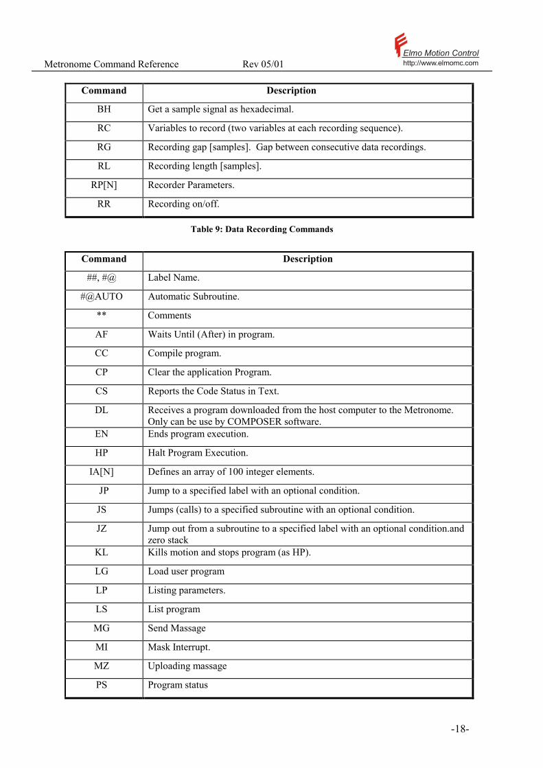
Command Description
BH Get a sample signal as hexadecimal.
RC Variables to record (two variables at each recording sequence).
RG Recording gap [samples]. Gap between consecutive data recordings.
RL Recording length [samples].
RP[N] Recorder Parameters.
RR Recording on/off.
Table 9: Data Recording Commands
Command Description
##, #@ Label Name.
#@AUTO Automatic Subroutine.
** Comments
AF Waits Until (After) in program.
CC Compile program.
CP Clear the application Program.
CS Reports the Code Status in Text.
DL Receives a program downloaded from the host computer to the Metronome. Only can be use by COMPOSER software.
EN Ends program execution.
HP Halt Program Execution.
IA[N] Defines an array of 100 integer elements.
JP Jump to a specified label with an optional condition.
JS Jumps (calls) to a specified subroutine with an optional condition.
JZ Jump out from a subroutine to a specified label with an optional condition.and zero stack
KL Kills motion and stops program (as HP).
LG Load user program
LP Listing parameters.
LS List program
MG Send Massage
MI Mask Interrupt.
MZ Uploading massage
PS Program status
Metronome Command Reference Rev 05/01 Elmo Motion Controlhttp://www.elmomc.com
- 19 -
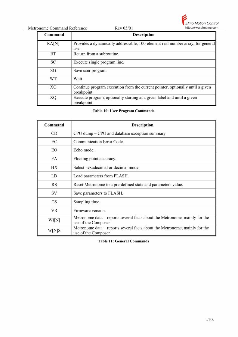
Command Description
RA[N] Provides a dynamically addressable, 100-element real number array, for general use.
RT Return from a subroutine.
SC Execute single program line.
SG Save user program
WT Wait
XC Continue program execution from the current pointer, optionally until a given breakpoint.
XQ Execute program, optionally starting at a given label and until a given breakpoint.
Table 10: User Program Commands
Command Description
CD CPU dump – CPU and database exception summary
EC Communication Error Code.
EO Echo mode.
FA Floating point accuracy.
HX Select hexadecimal or decimal mode.
LD Load parameters from FLASH.
RS Reset Metronome to a pre-defined state and parameters value.
SV Save parameters to FLASH.
TS Sampling time
VR Firmware version.
WI[N] Metronome data – reports several facts about the Metronome, mainly for the use of the Composer
W[N]S Metronome data – reports several facts about the Metronome, mainly for the use of the Composer
Table 11: General Commands

Metronome Command Reference Rev 05/01 Elmo Motion Controlhttp://www.elmomc.com
- 20 -
2.3 Alphabetical Commands Reference
This chapter presents all the Metronome commands in alphabetical order, including detailed definitions of each command and examples. The description of each command includes:
• Purpose: The operation or task of the command. • Attributes: The characteristics of the command.
Type: Action type, Attached variable type and attributes.
The action type may be: A Command: An instruction to do something. For example the command BG starts a new motion profile. A parameter: Data item that may be used later. For example, the AC (Acceleration) parameter is required for the calculation of later motions. A status inquiry: Get the state of the Metronome, such as the motor speed, a digital input, or the reason for the last motor failure. The parameters and some of the commands have attached numerical values. These may be: Integer: A 32 bit long integer Real: A 32 bit floating point number (IEEE style) String No value. Integer variables may have the following attributes: Bit field: The integer is not to be understood as a number but as a combination of binary fields. For example, the IP (digital input) command reads many On/Off switches to the same integer, allocating one bit for each. Option: A selector that may attain one of several options. For example the motor direction may be set to forward or reverse, symbolized by the numbers 0 and 1 respectively.
Overloaded: Some command names are used to access several internal variables, according to the context. For example, the analog gain AG command relates the voltage at the analog input to the amplifier command. In the speed-control unit mode, AG has the units of count/sec/volt. In the position mode, AG has the different units of counts/volt. The Metronome system has indeed several different setup parameters, each of them with different units, to define the analog gains at the different modes, but they are all accessed by the same command.
Source: Defines the agents that may use this command. These may be:
• RS232 communications • RS485 communications • CANopen communications • User program.
The command access rights are not equal for all the sources. For example, CANopen uses the object dictionary to read strings, not the string commands of this reference manual. Another example is the LS (List program) command that of coarse cannot be performed from within a program.
Metronome Command Reference Rev 05/01 Elmo Motion Controlhttp://www.elmomc.com
- 21 -
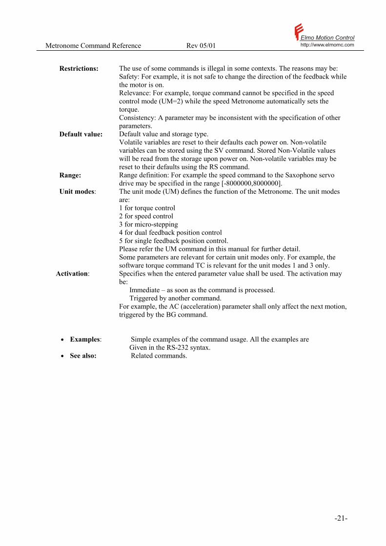
Restrictions: The use of some commands is illegal in some contexts. The reasons may be:
Safety: For example, it is not safe to change the direction of the feedback while the motor is on. Relevance: For example, torque command cannot be specified in the speed control mode (UM=2) while the speed Metronome automatically sets the torque. Consistency: A parameter may be inconsistent with the specification of other parameters.
Default value: Default value and storage type. Volatile variables are reset to their defaults each power on. Non-volatile variables can be stored using the SV command. Stored Non-Volatile values will be read from the storage upon power on. Non-volatile variables may be reset to their defaults using the RS command.
Range: Range definition: For example the speed command to the Saxophone servo drive may be specified in the range [-8000000,8000000].
Unit modes: The unit mode (UM) defines the function of the Metronome. The unit modes are: 1 for torque control 2 for speed control 3 for micro-stepping 4 for dual feedback position control 5 for single feedback position control. Please refer the UM command in this manual for further detail. Some parameters are relevant for certain unit modes only. For example, the software torque command TC is relevant for the unit modes 1 and 3 only.
Activation: Specifies when the entered parameter value shall be used. The activation may be:
Immediate – as soon as the command is processed. Triggered by another command.
For example, the AC (acceleration) parameter shall only affect the next motion, triggered by the BG command.
• Examples: Simple examples of the command usage. All the examples are Given in the RS-232 syntax.
• See also: Related commands.
Metronome Command Reference Rev 05/01 Elmo Motion Controlhttp://www.elmomc.com
- 22 -
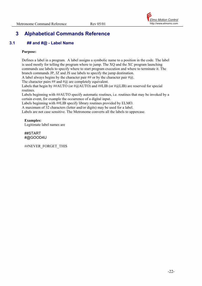
3 Alphabetical Commands Reference 3.1 ## and #@ - Label Name
Purpose: Defines a label in a program. A label assigns a symbolic name to a position in the code. The label is used mostly for telling the program where to jump. The XQ and the XC program launching commands use labels to specify where to start program execution and where to terminate it. The branch commands JP, JZ and JS use labels to specify the jump destination. A label always begins by the character pair ## or by the character pair #@. The character pairs ## and #@ are completely equivalent. Labels that begin by ##AUTO (or #@AUTO) and ##LIB (or #@LIB) are reserved for special routines. Labels beginning with ##AUTO specify automatic routines, i.e. routines that may be invoked by a certain event, for example the occurrence of a digital input. Labels beginning with ##LIB specify library routines provided by ELMO. A maximum of 32 characters (letter and/or digits) may be used for a label. Labels are not case sensitive. The Metronome converts all the labels to uppercase.
Examples: Legitimate label names are ##START #@GOOD4U ##NEVER_FORGET_THIS

Metronome Command Reference Rev 05/01 Elmo Motion Controlhttp://www.elmomc.com
- 23 -
3.2 #@AUTO_ - Automatic Routine
Purpose: The Metronome recognizes special subroutine names as automatic routines. Any of these routines will be automatically called if the routine exists and if:
- The related event occurred - The automatic routine is not masked (please refer MI). - No automatic routine with higher priority is pending (In that case the
automatic routine will be pending until the conditions to run it are created.
The automatic routines have priorities. If more then one automatic routine request execution, the one with the higher priority shall be treated first. The automatic routines follow the same rules as a standard subroutine. An automatic subroutine can be interrupted by another automatic routine, including itself if the event that drove it occurs again. An automatic routine can be made un-interruptible using the interrupt mask MI. All the automatic subroutines, except #@AUTOEXEC , are activated only if a program is running. The follow tables lists the automatic routine names and they’re related triggering events. Subroutine Name Triggering Event Priority
#@AUTOEXEC Starts immediately after power on. 1
#@AUTO_ER Any fault which disabled the motor. 2
#@AUTO_FLS #@AUTO_RLS
FLS or RLS going high, according to the polarity defined in IL[3] and IL[4].
3,4
#@AUTO_I1…I4 The related input is changed to 1. 5,6,7,8
Table 12: Automatic Subroutines

Metronome Command Reference Rev 05/01 Elmo Motion Controlhttp://www.elmomc.com
- 24 -
Examples: PR=10000;SP=100000;AC=1000000;DC=100000 ##LOOP BG AF,MS=0;JP##LOOP #@AUTO_I1;SP=150000;RT #@AUTO_I2;SP=50000;RT #@AUTO_I3;IA[1]=MI,MI=MI|1FEH,ST;MI=IA[1],RT EN The speed is increased if input bit 1 changes to 1, decreased if input bit 2 changes to 1 and stops if input 3 changes to 1. The AUTO_I3 routine blocks any event but a motor error from interrupting it. Note the use of the comma in IA[1]=MI,MI=MI|1. The comma states that these two commands are to be executed consecutively, without any interruption. This is necessary to avoid an interruption before MI is set. The comma in MI=IA[1],RT is required to assure that the routine indeed returns after the interrupt mask is restored, instead of branching to a nested automatic routine. See also: ##, #@, RT, MI

Metronome Command Reference Rev 05/01 Elmo Motion Controlhttp://www.elmomc.com
- 25 -
3.3 ** - Comment
Purpose: Defines a comment string within a program. The entire following string after the ** and until the next ‘;’ or carriage return (whichever comes first) is ignored. Examples: ** MY DEMO PROGRAM …. … BG;** START MOTION …

Metronome Command Reference Rev 05/01 Elmo Motion Controlhttp://www.elmomc.com
- 26 -
3.4 AC – Acceleration
Purpose: Defines the maximum acceleration in [counts/sec2]. This parameter is used in profiled speed control mode (UM=2,PM=1), and in position point-to-point and jogging motions (UM=4, and UM=5). The AC parameter does not affect the present motion. If will be used for the planning of the next motion, initiated by a BG command. For detailed explanations, please refer the Motion Profiling section in the Software Reference Manual. Attributes: Type: Parameter, Integer Overloaded: No Source: Program, RS232/RS485, CANopen Restrictions: None Default value: 200000 (RS), Non volatile Range: [100, 60000000] Unit modes: UM=2,4,5 Activation: MO=1 or BG
Typical applications: 1. Define acceleration limits for the motion (UM=2) 2. Plan a profiled motion (UM=4,UM=5) Examples: The following example enters motion-profiling parameters. AC=1000000;DC=1000000;SF=20 BG See also: DC, SF, SD, PM
Metronome Command Reference Rev 05/01 Elmo Motion Controlhttp://www.elmomc.com
- 27 -
3.5 AF – Wait Until (After)
Purpose: Suspends the execution of the program until a specified condition is satisfied.
Attributes: Type: Command, String Overloaded: No Source: Program Restrictions: None. Unit modes: All Activation: Immediate Examples: PR=1000000;BG AF,MS=0; BG; Starts a point-to-point motion, waits until the motion ends and then begins the next motion. See also: JP, JS, JZ, WT
Metronome Command Reference Rev 05/01 Elmo Motion Controlhttp://www.elmomc.com
- 28 -
3.6 AG[N] - Analog Gain Array
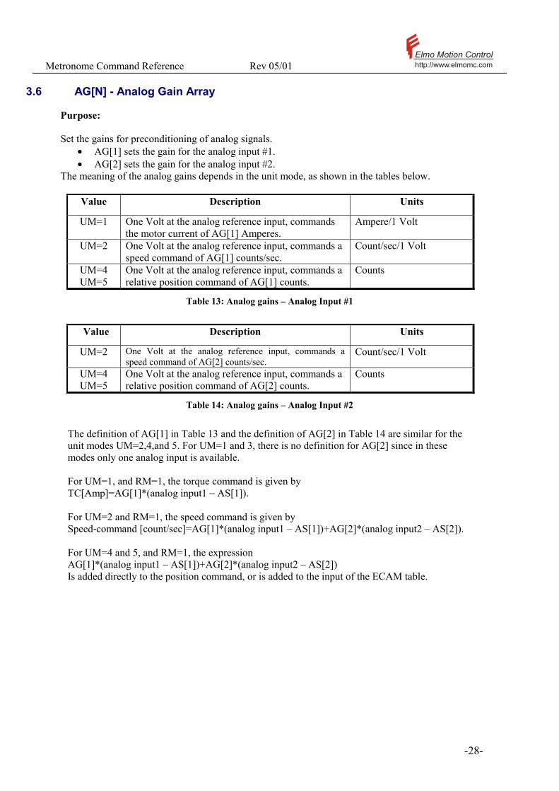
Purpose: Set the gains for preconditioning of analog signals.
• AG[1] sets the gain for the analog input #1. • AG[2] sets the gain for the analog input #2.
The meaning of the analog gains depends in the unit mode, as shown in the tables below.
Value Description Units
UM=1 One Volt at the analog reference input, commands the motor current of AG[1] Amperes.
Ampere/1 Volt
UM=2 One Volt at the analog reference input, commands a speed command of AG[1] counts/sec.
Count/sec/1 Volt
UM=4 UM=5
One Volt at the analog reference input, commands a relative position command of AG[1] counts.
Counts
Table 13: Analog gains – Analog Input #1
Value Description Units
UM=2 One Volt at the analog reference input, commands a speed command of AG[2] counts/sec.
Count/sec/1 Volt
UM=4 UM=5
One Volt at the analog reference input, commands a relative position command of AG[2] counts.
Counts
Table 14: Analog gains – Analog Input #2
The definition of AG[1] in Table 13 and the definition of AG[2] in Table 14 are similar for the unit modes UM=2,4,and 5. For UM=1 and 3, there is no definition for AG[2] since in these modes only one analog input is available. For UM=1, and RM=1, the torque command is given by TC[Amp]=AG[1]*(analog input1 – AS[1]). For UM=2 and RM=1, the speed command is given by Speed-command [count/sec]=AG[1]*(analog input1 – AS[1])+AG[2]*(analog input2 – AS[2]). For UM=4 and 5, and RM=1, the expression AG[1]*(analog input1 – AS[1])+AG[2]*(analog input2 – AS[2]) Is added directly to the position command, or is added to the input of the ECAM table.

Metronome Command Reference Rev 05/01 Elmo Motion Controlhttp://www.elmomc.com
- 29 -
The polarity of an analog reference signal may be reversed by setting the sign of the relevant AG[N] parameter. Attributes: Type: Parameter, Real Overloaded: Yes Source: Program, RS232/RS485, CANopen Restrictions: MO=0 Default value: AG[1]: 1
AG[2]: 0 (RS), Non volatile Index range 1 and 2 Range: UM=1,3: [-MC/10,MC/10]
UM=2 : [-6000000,6000000] UM=4 : [-XM/20,XM/20] ] (XM=0 is equivalent to XM= 312 ) UM=5: [-YM/20,YM/20] (YM=0 is equivalent to YM= 312 )
Unit modes: All Activation: MO=1
! The AG[] parameters are overloaded. It means that the command mnemonic AG refers to different variables in the different unit modes. Please refer the example below.
! Please refer the RM command for a detailed explanation of the position-reference generation model.
Metronome Command Reference Rev 05/01 Elmo Motion Controlhttp://www.elmomc.com
- 30 -
Examples: UM=1; AG[1]=2; Two amperes will flow in the motor for each volt at analog input #1. Analog input #2 will not affect the motor current. Continuing the previous example, the commands UM=2 AG[1]=1000; define that the speed command will be 1000 counts/sec per 1 volt at analog input #1. The commands at the speed mode (UM=2) do not change the analog gain for the torque command mode (UM=1), as is seen by typing UM=1; AG[1] 2; The commands UM=5;RM=1;AG[1]=1000; define that in the single-feedback position control mode, the motor position will change in 1000 counts per one Volt change at Analog input #1. See also: UM, RM, TG, AS, EM, ET
Metronome Command Reference Rev 05/01 Elmo Motion Controlhttp://www.elmomc.com
- 31 -
3.7 AM - Analog Mode
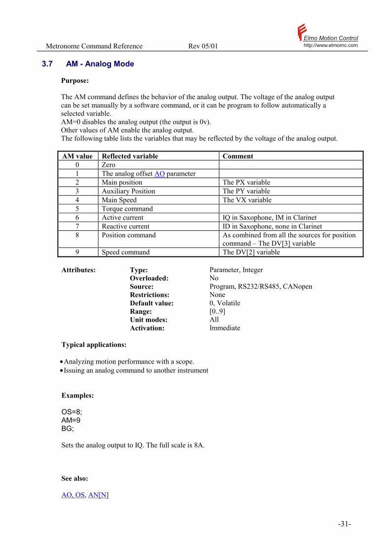
Purpose: The AM command defines the behavior of the analog output. The voltage of the analog output can be set manually by a software command, or it can be program to follow automatically a selected variable. AM=0 disables the analog output (the output is 0v). Other values of AM enable the analog output. The following table lists the variables that may be reflected by the voltage of the analog output. AM value Reflected variable Comment
0 Zero 1 The analog offset AO parameter 2 Main position The PX variable 3 Auxiliary Position The PY variable 4 Main Speed The VX variable 5 Torque command 6 Active current IQ in Saxophone, IM in Clarinet 7 Reactive current ID in Saxophone, none in Clarinet 8 Position command As combined from all the sources for position
command – The DV[3] variable 9 Speed command The DV[2] variable
Attributes: Type: Parameter, Integer Overloaded: No Source: Program, RS232/RS485, CANopen Restrictions: None Default value: 0, Volatile Range: [0..9] Unit modes: All Activation: Immediate Typical applications: • Analyzing motion performance with a scope. • Issuing an analog command to another instrument Examples: OS=8; AM=9 BG; Sets the analog output to IQ. The full scale is 8A. See also: AO, OS, AN[N]
Metronome Command Reference Rev 05/01 Elmo Motion Controlhttp://www.elmomc.com
- 32 -
3.8 AN[N] - Analog Inputs Array
Purpose:
• AN[1] - Reports the analog input 1 value, in [v]. • AN[2] - Reports the analog input 2 value, in [v]. • AN[3] – Reports the measured current in the motor A phase, in[A] • AN[4] - Reports the measured current in the motor B phase, in[A]. SAX Only • AN[5] - Reports the line voltage value, in [v]. SAX Only
Attributes: Type: Status report, Real Overloaded: No Source: Program, RS232/RS485, CANopen Restrictions: None Unit modes: All Typical applications: 1. Reading external sensors 2. Verification of analog reference 3. Reading the phase currents and line voltage.
Metronome Command Reference Rev 05/01 Elmo Motion Controlhttp://www.elmomc.com
- 33 -
Examples: Following program control the digital output according to the analog input readout. AN[1] higher then 1 volt turn off digital output 1 and below –1 turn on digital output 1. AN[2] does the same for digital output 2. ##START OP=0 ##LOOP JP##OP1_ON,AN[1]<-1 JP##OP2_ON,AN[2]<-1 JP##OP1_OFF,AN[1]>1 JP##OP2_OFF,AN[2]>1 JP##LOOP ##OP1_ON OB[1]=1 JP##LOOP ##OP2_ON OB[2]=1 JP##LOOP ##OP1_OFF OB[1]=0 JP##LOOP ##OP2_OFF OB[2]=0 JP##LOOP EN See also: AS, AG
Metronome Command Reference Rev 05/01 Elmo Motion Controlhttp://www.elmomc.com
- 34 -
3.9 AO - Analog Output
Purpose: AO Sets the analog output value, in Volts. This parameter affects the analog output only if AM=1. Attributes: Type: Parameter, Real Overloaded: No Source: Program, RS232/RS485, CANopen Restrictions: None Default value: 0, Volatile Range: [-10.0, 10.0] Unit modes: All Activation: Immediate See also: AM, OS
Metronome Command Reference Rev 05/01 Elmo Motion Controlhttp://www.elmomc.com
- 35 -
3.10 AS[N] - Analog Inputs Offsets Array
Purpose: The AS[N] variables compensate for offsets of the analog signals. The signals at the A/D converter may be offset – the A/D reading may be nonzero when a zero reading is desired. The offset may be caused by the limited precision of the Metronome electronics. The offset may disturb normal operation. An offset reference or feedback signal may cause a motor to “crawl” when a complete stop is desired. The Analog offset subtracts from the analog input as follows: Corrected signal = D/A reading – Analog offset.
• AS[1] - Analog input offset command, in [v]. • AS[2] - Analog input offset feedback, in [v]. Attributes: Type: Parameter, Real Overloaded: No Source: Program, RS232/RS485, CANopen Restrictions: None Default value: 0 (RS), Non-volatile Range: [-10.0, 10.0] Unit modes: All Activation: Immediate
! The actual resolution of AS[N] is about 5 millivolt. See also: AG, RM

Metronome Command Reference Rev 05/01 Elmo Motion Controlhttp://www.elmomc.com
- 36 -
3.11 BG - Begin Motion
Purpose: The BG command starts immediately the next programmed motion. In speed mode, it activates the latest JV, and also the new AC, DC, and SF values. In the analog speed reference mode (UM=2,RM=1) the BG command is only used to activate the motion parameters AC, DC, and SF. In stepper mode, it activates the programmed stepper angle. In the position modes, BG begins the latest position mode programmed – it may be a point-to-point motion, a jogging motion, or any type of tabulated motion (PVT or PT). Each mode of motion enters with its entire set of parameters. For example, starting a Point-to-Point motion activates the present values of AC,DC,SP, and SF. The BG command may be used to modify the parameters of the present mode, not only for programming new modes. For example, A BG command in the Point-to-Point mode modifies the active AC parameter (and all the other active motion parameters) with its last programmed value. A BG command overrides and cancels a pending BI command. Attributes: Type: Command, No value Overloaded: No Source: Program, RS232/RS485, CANopen Restrictions: MO=1 Unit modes: All excluding UM=1 Activation: Immediate See also: BI, MO, UM
Metronome Command Reference Rev 05/01 Elmo Motion Controlhttp://www.elmomc.com
- 37 -
3.12 BH – Get a Single Signal as Hexadecimal
Purpose: The BH command is used to upload the values recorder by the recorder to a host. The BH command is designed to optimize the data transfer from the Metronome to the host, assuming that the host has the computing power to analyze the Metronome message. The message is not designed for easy human interpretation. The basic condition for executing a BH command is that valid data is stored in the recorder for uploading. In that case the fields of the RC variable define the variables that had been recorded. The command BH=n will upload the recorded variable defined by RC&n , where & is the bit-wise AND operator. For example, if RC=7, the command BH=2 will bring the variable that would be recorded by setting RC=2, since 7&2=2. BH=3 is illegal, since the binary representation of BH includes more then one ‘1’ and the recorded variable is not uniquely defined. BH=16 will return an error since BH&RC=0. The BH parameter is defined as a bit-field, so that BH=10h is equivalent to BH=16. The data is uploaded in hexadecimal form. This is done in order to minimize the transmission time (relative to ASCII formatted text), while adhering to the ASCII nature of the Metronome transmissions. Each data byte is parted to two nibbles, and the ASCII code of the nibbles is sent from the Metronome to the Host. For example, the short integer number 43794 has the hexadecimal representation AB12. It will be transmitted as ‘A’,’B’,’1’,’2’, with the most significant nibble first and the least significant nibble last. The long integer number 1 will be sent as ‘0’ ‘0’ ‘0’ ‘0’ ‘0’ ‘0’ ‘0’ ‘1’. In order to analyze the BH record, one have to understand that the internal representation of quantities inside the metronome is not in user units. For example, the user desires the recorded motor current in Amperes, but the Metronome represents currents internally by the bits of the A/D that measures the current. The BH record uploads recorded currents (and other variables as well) in their internal representation units-and it also provides the scaling multiplier to bring it into user units. That way, no multiplication inaccuracies are introduced to the BH records, and Metronome CPU time is saved. The record transmitted by the Metronome in response to a BH=n command is described below. The record includes 20 bytes of overhead, and numerical records data. The values in the table are translated to ASCII as explained above.

Metronome Command Reference Rev 05/01 Elmo Motion Controlhttp://www.elmomc.com
- 38 -
Byte Number Value Type
0-1: Variable type for user.
0 for integer 1 for real
Byte
2-3: Data width – number of hex character of a single transmitted data item.
4 for short integer, 8 for long integer.
Byte
4-7: Data length – The actual number of transmitted data items. Note that if RP[8] and RP[9] are not zero, this number is not equal to RL.
Word
8-11: Variable time multiplier. This is the number in which TS must be multiplied to obtain the basic period of the recorder.
4 for Sax speed and position modes. 1 For Sax torque and stepper modes
1 For Clarinet
Word
12-19: Floating number factor. Multiply every uploaded data item by this number in order to convert it to user units, such as Amperes, or Count/sec.
32 bit Float number in the IEEE format.
20 – 20 + (Data Length)*( Data width) –1 : Data items. The oldest record is transmitted first, and the most recent record is transmitted last.
Words or long integers, according to the Data Width
Table 15: BH – record structure
The transmission of a BH record can be quite long. A record of 2000 long numbers is about 8000 bytes, which take at least 4 seconds to transmit in RS232 in the baud rate of 19200. In this time: The user program continues to run normally. CAN commands are accepted and processed normally. RS232 commands are accepted and executed normally, but the transmission of the response to them is deferred until the BH upload completion. RS485 commands can be sent only after aborting the BH transmission. Sending any RS485 character to the Metronome while it is transmitting on the RS485 lines will cause the Metronome to abort transmission immediately. Attributes: Type: Command, Integer, Bit-field Overloaded: No Source: RS232/RS485 Restrictions: RR=0 (Valid recorder data is ready)
Not executing an earlier requested BH=n command Unit modes: All Activation: Immediate See also: TS, RC, RP, RR, RG, RL,
Metronome Command Reference Rev 05/01 Elmo Motion Controlhttp://www.elmomc.com
- 39 -
3.13 BI - Begin On Input
Purpose:
A BG command suspended until any combination (0/1/Don’t care) of digital inputs 1,2,3, and 4 attains a desired pattern. The uncared digital inputs are defined by the BM variable. The desired polarity of the cared digital inputs is defined by the argument of the BM command. A new BI command overrides any pending BI. Use the MS command to observe if a pending BG has already been executed. Use BI=16 to cancel a pending BI command.
Attributes: Type: Command, Integer, Bit-field Overloaded: No Source: Program, RS232/RS485, CANopen Restrictions: MO=1.
In UM=2: RM=0 Range 0-16 Unit modes: All excluding UM=1 Activation: Immediate
Typical applications: Start motion with hardware timing Examples: BM=3; BI=1 The above code waits for Digital input 1 to be high, and for digital input 2 to be low for starting a motion. The digital inputs 3 and 4 are not cared. BM=3; AF,MS<>2; The above code places a suspended begin requests, and then suspends program execution until the suspended BG is actually executed. See also: BG, BM, IB, MS

Metronome Command Reference Rev 05/01 Elmo Motion Controlhttp://www.elmomc.com
- 40 -
3.14 BM – Begin mask
Purpose: Defines which digital inputs are to be watched in a suspended begin (BI) command. The following table details the inputs watched for the possible BM values.
Value IB[1] IB[2] IB[3] IB[4] Comment
0 Ignore Ignore Ignore Ignore No inputs are watched. Motion will start immediately upon a BI command, regardless of the argument of BI.
1 Watch Ignore Ignore Ignore 2 Ignore Watch Ignore Ignore 3 Watch Watch Ignore Ignore 4 Ignore Ignore Watch Ignore 5 Watch Ignore Watch Ignore 6 Ignore Watch Watch Ignore 7 Watch Watch Watch Ignore 8 Ignore Ignore Ignore Watch 9 Watch Ignore Ignore Watch
10 Ignore Watch Ignore Watch 11 Watch Watch Ignore Watch 12 Ignore Ignore Watch Watch 13 Watch Ignore Watch Watch 14 Ignore Watch Watch Watch 15 Watch Watch Watch Watch
Table 16: BM – Begin mask
From the time a BI command is issued and until it is executed, the digital inputs are continuously watched according to the value of BM. If BM is modified at this time, it will not affect the pending BI command – only the next one. Attributes: Type: Parameter, Integer, Bit field Overloaded: No Source: Program, RS232/RS485, CANopen Restrictions: None Default value: 0 (RS), Non-volatile Range: [0..15] Unit modes: All, Excluding UM=1 Activation: BI See also: BI, BG, IB, MS
Metronome Command Reference Rev 05/01 Elmo Motion Controlhttp://www.elmomc.com
- 41 -
3.15 CA – Commutation Array
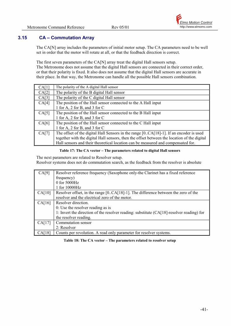
The CA[N] array includes the parameters of initial motor setup. The CA parameters need to be well set in order that the motor will rotate at all, or that the feedback direction is correct. The first seven parameters of the CA[N] array treat the digital Hall sensors setup. The Metronome does not assume that the digital Hall sensors are connected in their correct order, or that their polarity is fixed. It also does not assume that the digital Hall sensors are accurate in their place. In that way, the Metronome can handle all the possible Hall sensors combination.
CA[1] The polarity of the A digital Hall sensor CA[2] The polarity of the B digital Hall sensor CA[3] The polarity of the C digital Hall sensor CA[4] The position of the Hall sensor connected to the A Hall input
1 for A, 2 for B, and 3 for C CA[5] The position of the Hall sensor connected to the B Hall input
1 for A, 2 for B, and 3 for C CA[6] The position of the Hall sensor connected to the C Hall input
1 for A, 2 for B, and 3 for C CA[7] The offset of the digital Hall Sensors in the range [0..CA[18]-1]. If an encoder is used
together with the digital Hall sensors, then the offset between the location of the digital Hall sensors and their theoretical location can be measured and compensated for.
Table 17: The CA vector – The parameters related to digital Hall sensors
The next parameters are related to Resolver setup. Resolver systems does not do commutation search, as the feedback from the resolver is absolute
CA[9] Resolver reference frequency (Saxophone only-the Clarinet has a fixed reference frequency) 0 for 5000Hz 1 for 10000Hz
CA[10] Resolver offset, in the range [0..CA[18]-1]. The difference between the zero of the resolver and the electrical zero of the motor.
CA[16] Resolver direction. 0: Use the resolver reading as is 1: Invert the direction of the resolver reading: substitute (CA[18]-resolver reading) for the resolver reading.
CA[17] Commutation sensor 2: Resolver
CA[18] Counts per revolution. A read only parameter for resolver systems.
Table 18: The CA vector – The parameters related to resolver setup
Metronome Command Reference Rev 05/01 Elmo Motion Controlhttp://www.elmomc.com
- 42 -
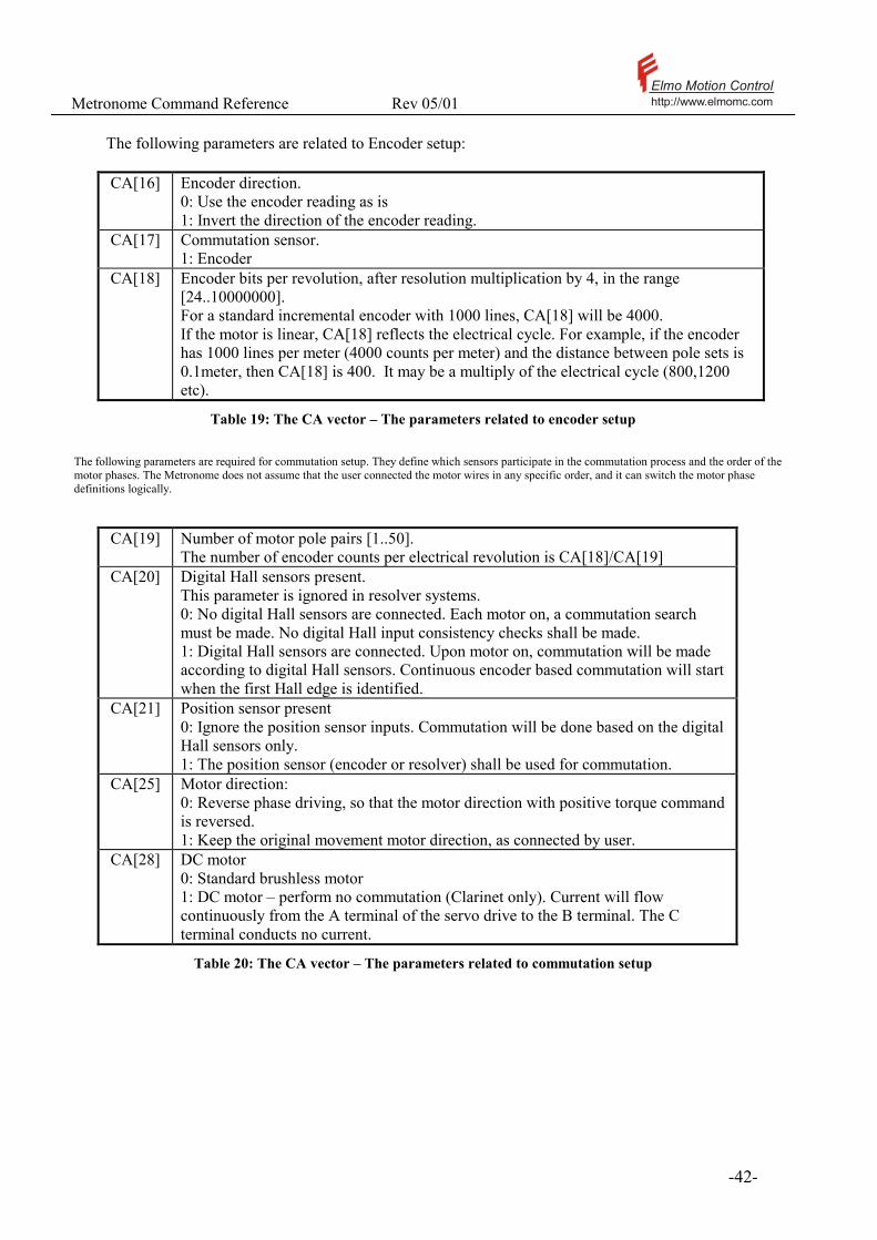
The following parameters are related to Encoder setup:
CA[16] Encoder direction.
0: Use the encoder reading as is 1: Invert the direction of the encoder reading.
CA[17] Commutation sensor. 1: Encoder
CA[18] Encoder bits per revolution, after resolution multiplication by 4, in the range [24..10000000]. For a standard incremental encoder with 1000 lines, CA[18] will be 4000. If the motor is linear, CA[18] reflects the electrical cycle. For example, if the encoder has 1000 lines per meter (4000 counts per meter) and the distance between pole sets is 0.1meter, then CA[18] is 400. It may be a multiply of the electrical cycle (800,1200 etc).
Table 19: The CA vector – The parameters related to encoder setup
The following parameters are required for commutation setup. They define which sensors participate in the commutation process and the order of the motor phases. The Metronome does not assume that the user connected the motor wires in any specific order, and it can switch the motor phase definitions logically.
CA[19] Number of motor pole pairs [1..50]. The number of encoder counts per electrical revolution is CA[18]/CA[19]
CA[20] Digital Hall sensors present. This parameter is ignored in resolver systems. 0: No digital Hall sensors are connected. Each motor on, a commutation search must be made. No digital Hall input consistency checks shall be made. 1: Digital Hall sensors are connected. Upon motor on, commutation will be made according to digital Hall sensors. Continuous encoder based commutation will start when the first Hall edge is identified.
CA[21] Position sensor present 0: Ignore the position sensor inputs. Commutation will be done based on the digital Hall sensors only. 1: The position sensor (encoder or resolver) shall be used for commutation.
CA[25] Motor direction: 0: Reverse phase driving, so that the motor direction with positive torque command is reversed. 1: Keep the original movement motor direction, as connected by user.
CA[28] DC motor 0: Standard brushless motor 1: DC motor – perform no commutation (Clarinet only). Current will flow continuously from the A terminal of the servo drive to the B terminal. The C terminal conducts no current.
Table 20: The CA vector – The parameters related to commutation setup

Metronome Command Reference Rev 05/01 Elmo Motion Controlhttp://www.elmomc.com
- 43 -
CA[15] Signal frequency for the commutation search process CA[24] The minimal motor movement to perform result analysis CA[26] Starting torque for the motor-on commutation search process CA[27] Rate for increasing the motor torque
Table 21: The CA vector – The parameters related to automatic commutation search
CA[8] 0: The main speed is derived from the position measurement
1: Analog input #2 is set to Tacho feedback (Clarinet only) Please refer the TG command for details.
CA[23] Counts per meter (any positive integer) 0: Rotary motor 1: Counts per meter in a linear motor. This parameter is not used directly by the Metronome – it is just stored there for the convenience of the composer. Please refer to CA[18].
CA[29] Current loop gain (Clarinet only) 0: High gain 1: Low gain
Table 22: The CA vector – Miscellaneous parameters
Attributes: Type: Parameter, Integer Overloaded: No Source: Program, RS232/RS485, CANopen Restrictions: MO=0 Default value: CA[1]=CA[2]=CA[3]=1, CA[4]=3, CA[5]=2,
CA[6]=1, CA[9]=1, CA[15]=4, CA[16]=3, CA[16]=1, CA[18]=4096, CA[19]=2, CA[21]=1 CA[20] = (0/1) for (Encoder/Resolver), All the other CA parameters are 0 (RS), Non-volatile
Range: As defined in the table above. Unit modes: All Activation: Immediate.
! The CA[N] parameters are usually automatically set by the Composer program. Please avoid setting the CA[N] parameters manually unless you are very sure of what you are doing. See also: MO, TG
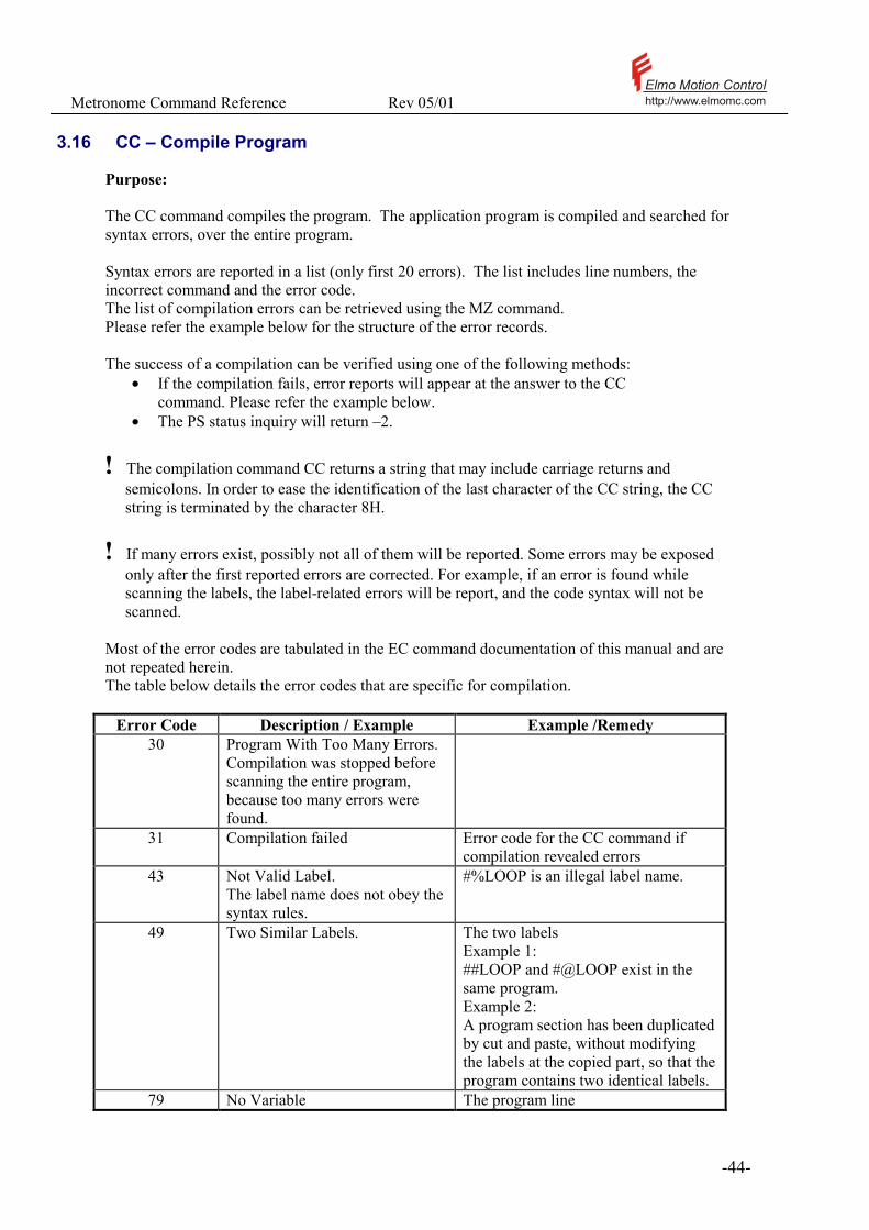
Metronome Command Reference Rev 05/01 Elmo Motion Controlhttp://www.elmomc.com
- 44 -
3.16 CC – Compile Program
Purpose: The CC command compiles the program. The application program is compiled and searched for syntax errors, over the entire program. Syntax errors are reported in a list (only first 20 errors). The list includes line numbers, the incorrect command and the error code. The list of compilation errors can be retrieved using the MZ command. Please refer the example below for the structure of the error records. The success of a compilation can be verified using one of the following methods:
• If the compilation fails, error reports will appear at the answer to the CC command. Please refer the example below.
• The PS status inquiry will return –2.
! The compilation command CC returns a string that may include carriage returns and semicolons. In order to ease the identification of the last character of the CC string, the CC string is terminated by the character 8H.
! If many errors exist, possibly not all of them will be reported. Some errors may be exposed only after the first reported errors are corrected. For example, if an error is found while scanning the labels, the label-related errors will be report, and the code syntax will not be scanned.
Most of the error codes are tabulated in the EC command documentation of this manual and are not repeated herein. The table below details the error codes that are specific for compilation.
Error Code Description / Example Example /Remedy 30 Program With Too Many Errors.
Compilation was stopped before scanning the entire program, because too many errors were found.
31 Compilation failed Error code for the CC command if compilation revealed errors
43 Not Valid Label. The label name does not obey the syntax rules.
#%LOOP is an illegal label name.
49 Two Similar Labels.
The two labels Example 1: ##LOOP and #@LOOP exist in the same program. Example 2: A program section has been duplicated by cut and paste, without modifying the labels at the copied part, so that the program contains two identical labels.
79 No Variable The program line
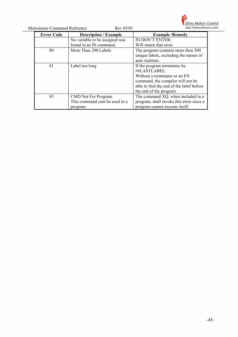
Metronome Command Reference Rev 05/01 Elmo Motion Controlhttp://www.elmomc.com
- 45 -
Error Code Description / Example Example /Remedy No variable to be assigned was found in an IN command.
IN DON’T ENTER; Will return that error.
80 More Than 200 Labels The program contains more then 200 unique labels, excluding the names of auto routines.
81 Label too long If the program terminates by ##LASTLABEL Without a terminator or an EN command, the compiler will not be able to find the end of the label before the end of the program.
83 CMD Not For Program. This command cant be used in a program.
The command XQ, when included in a program, shall invoke this error since a program cannot execute itself.
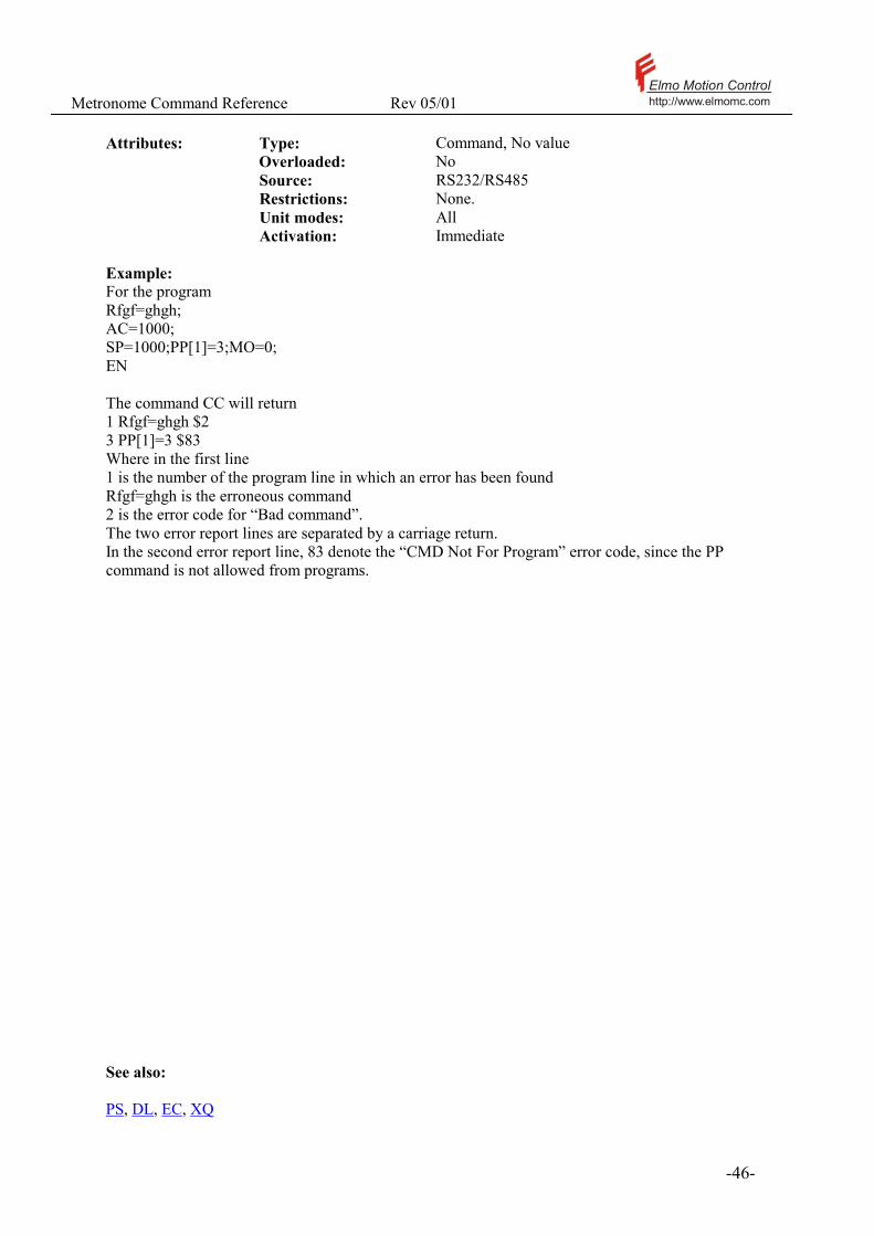
Metronome Command Reference Rev 05/01 Elmo Motion Controlhttp://www.elmomc.com
- 46 -
Attributes: Type: Command, No value Overloaded: No Source: RS232/RS485 Restrictions: None. Unit modes: All Activation: Immediate Example: For the program Rfgf=ghgh; AC=1000; SP=1000;PP[1]=3;MO=0; EN The command CC will return 1 Rfgf=ghgh $2 3 PP[1]=3 $83 Where in the first line 1 is the number of the program line in which an error has been found Rfgf=ghgh is the erroneous command 2 is the error code for “Bad command”. The two error report lines are separated by a carriage return. In the second error report line, 83 denote the “CMD Not For Program” error code, since the PP command is not allowed from programs. See also: PS, DL, EC, XQ

Metronome Command Reference Rev 05/01 Elmo Motion Controlhttp://www.elmomc.com
- 47 -
3.17 CD – CPU dump
Purpose: CD returns the status of the CPU and the status of the database. Call CD if:
• The SR report indicates a CPU exception • The MF report indicates a CPU exception • An attempt to start the motor returns the error code 54 “Bad data base”. • The CD report returns a string as the following: • Null Address=0 • Failure address=0 • Called Handler=none • Database Status: • Database O.k
Null Address is the code address of which a CPU exception occurred. An “0” indicates a normal condition. Failure Address is the code address at which a stack overflow occurred. An “0” indicates a normal condition. Called Handler is the type of CPU exception that occurred. “none” indicates a normal condition. Database status indicates if the recent database check at MO=1 or at power up revealed a consistent database. “Database O.k” indicates the normal condition.
Attributes: Type: Status report, String Overloaded: No Source: Program, RS232/RS485 Restrictions: None Unit modes: All
! For CANopen users, please use object 2080H of the OD via SDO access.
! If a CPU exception or a stack overflow occurs, please write down the entire CD report and ask for technical support.
Example: Null Address=0 Failure address=0 Called Handler=none Database Status: CA[4], error code=37 The above CD report tells that the database is inconsistent since two of the parameters CA[4], CA[5], or CA[6] are equal.
See also: MF, SR, MO
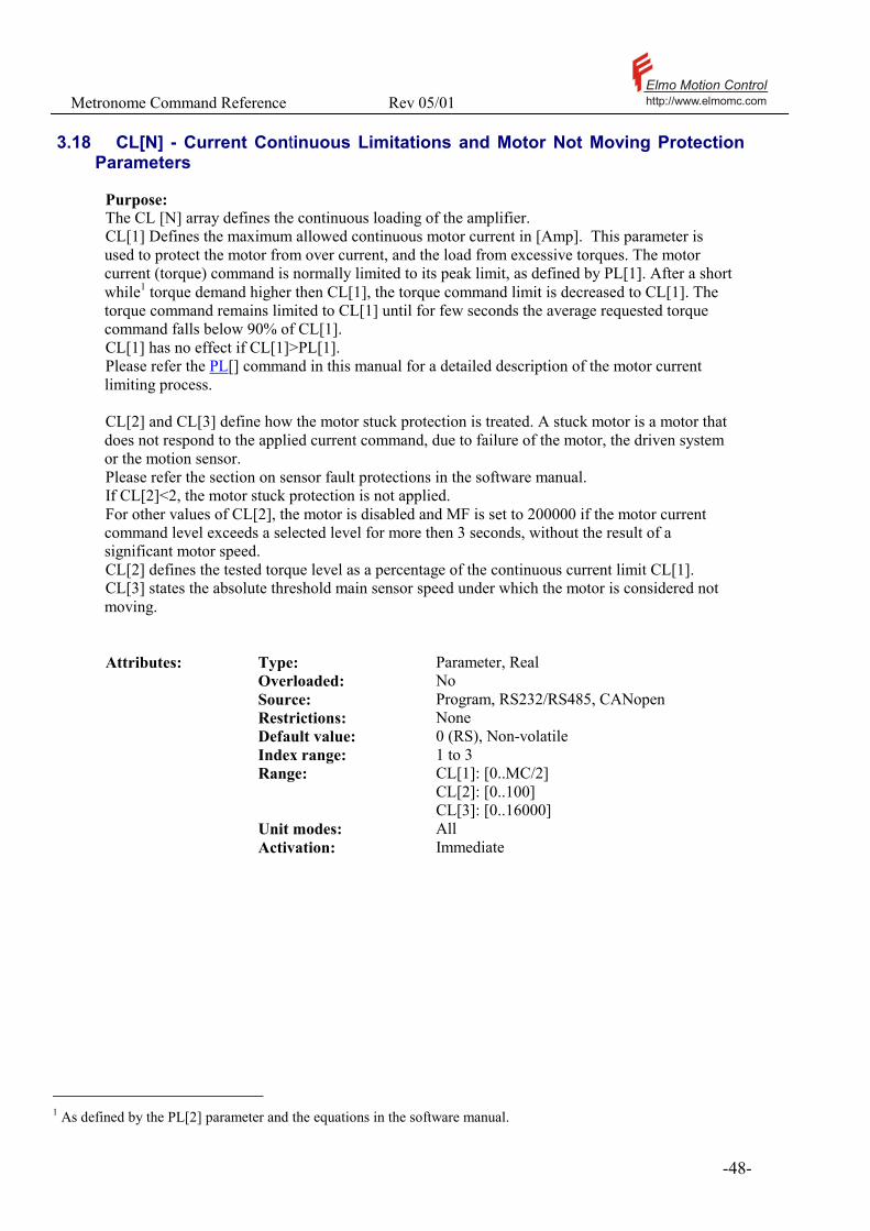
Metronome Command Reference Rev 05/01 Elmo Motion Controlhttp://www.elmomc.com
- 48 -
3.18 CL[N] - Current Continuous Limitations and Motor Not Moving Protection Parameters
Purpose: The CL [N] array defines the continuous loading of the amplifier. CL[1] Defines the maximum allowed continuous motor current in [Amp]. This parameter is used to protect the motor from over current, and the load from excessive torques. The motor current (torque) command is normally limited to its peak limit, as defined by PL[1]. After a short while1 torque demand higher then CL[1], the torque command limit is decreased to CL[1]. The torque command remains limited to CL[1] until for few seconds the average requested torque command falls below 90% of CL[1]. CL[1] has no effect if CL[1]>PL[1]. Please refer the PL[] command in this manual for a detailed description of the motor current limiting process. CL[2] and CL[3] define how the motor stuck protection is treated. A stuck motor is a motor that does not respond to the applied current command, due to failure of the motor, the driven system or the motion sensor. Please refer the section on sensor fault protections in the software manual. If CL[2]<2, the motor stuck protection is not applied. For other values of CL[2], the motor is disabled and MF is set to 200000 if the motor current command level exceeds a selected level for more then 3 seconds, without the result of a significant motor speed. CL[2] defines the tested torque level as a percentage of the continuous current limit CL[1]. CL[3] states the absolute threshold main sensor speed under which the motor is considered not moving. Attributes: Type: Parameter, Real Overloaded: No Source: Program, RS232/RS485, CANopen Restrictions: None Default value: 0 (RS), Non-volatile Index range: 1 to 3 Range: CL[1]: [0..MC/2]
CL[2]: [0..100] CL[3]: [0..16000]
Unit modes: All Activation: Immediate
1 As defined by the PL[2] parameter and the equations in the software manual.

Metronome Command Reference Rev 05/01 Elmo Motion Controlhttp://www.elmomc.com
- 49 -
Notes: 1. The motor not moving protection is always taken with regard to the main sensor. In dual
loop applications, this protection will not guard failures in the auxiliary sensor. 2. For some application, like thread fastening, the motor is legitimately brought to stop with
full continuous torque. For these applications, use CL[2]=0. 3. The time constant of 3 seconds is taken since almost every motion system applies high
torques for short acceleration periods while the speed is slow. Example If CL[2]=50 and CL[3]=500, the Metronome will abort (reset to MO=0) if the a torque level is kept at least 50% of the continuous current, while the shaft speed do not exceed 500 counts/sec for continuous 3 seconds. See also: LC, MC, PL[N], TC, MF
Metronome Command Reference Rev 05/01 Elmo Motion Controlhttp://www.elmomc.com
- 50 -
3.19 CP - Clear Program
Purpose: CP Clears the application program from volatile memory of the Metronome. The CP command does not affect the Flash memory. In order to clear the flash memory use the following command line: CP;SG; The CP command clears program in the RAM and then the SG command loads the empty RAM to the Flash
Attributes: Type: Command, No value Overloaded: No Source: RS232/RS485 Restrictions: None. Unit modes: All Activation: Immediate
See also: SG

Metronome Command Reference Rev 05/01 Elmo Motion Controlhttp://www.elmomc.com
- 51 -
3.20 CS - Code Status
Purpose: CS Reports the program Status. This command sends to the host the line number of the next instruction to be executed, and the next instruction itself.
Attributes: Type: Command, No value Overloaded: No Source: RS232/RS485 Restrictions: None. Unit modes: All Activation: Immediate Examples: 5 MO=1;BG
The above line, as an answer to a CS command, means that program is now running in line 5, and the next command to execute is MO=1. Line 5 may include more instructions before the MO=1, but they will not be seen in the CS output. See also: PS

Metronome Command Reference Rev 05/01 Elmo Motion Controlhttp://www.elmomc.com
- 52 -
3.21 DC – Deceleration
Purpose: DC Defines the maximum deceleration in [counts/sec2]. This parameter is used in profiled speed control mode (UM=2,PM=1), and in position point-to-point and jogging motions (UM=4, and UM=5). The DC parameter does not affect the present motion. If will be used for the planning of the next motion, initiated by a BG command. For detailed explanations, please refer the Motion Profiling section in the Software Reference Manual. Attributes: Type: Parameter, Integer Overloaded: No Source: Program, RS232/RS485, CANopen Restrictions: None Default value: 200000 (RS), Non volatile Range: [100, 60000000] Unit modes: UM=2,4,5 Activation: MO=1 or BG Typical applications: 1. Define acceleration limits for the motion (UM=2) 2. Plan a profiled motion (UM=4,UM=5) Examples: The following example enters motion-profiling parameters. AC=1000000;DC=1000000;SF=20 BG See also: AC, SF, SD, PM

Metronome Command Reference Rev 05/01 Elmo Motion Controlhttp://www.elmomc.com
- 53 -
3.22 DL - Download Program
Purpose: Receives a program downloaded from the host computer to the Metronome. The text of the program is sent as the string argument of the DL command. The argument of the DL command can be, however, no longer then 1000 characters, which may not suffice for the program. For this reason, not all the program needs to be sent in one piece. The program may be chopped, and downloaded to the composer in parts. Each new DL command appends new text to the program. The end of program segment transmission is marked by a backslash ‘\’ character. It is advised to command CP to clear the program area before trying to upload a program. This assures that the next DL will begin a fresh program, and not append itself to an existing text. The DL command by itself does not initialize compilation of the program, since it does not know when the entire program has been downloaded. ! For RS485 communication, the program text attached to the DL command must be no longer then 200 characters. Notes:
- The syntax of the DL command is slightly different from all the other commands. All the commands are terminated by ‘;’. The DL command may include the character ‘;’ many times in the string it delivers, so that the DL command is terminated by a ‘\’ character instead.
- The Metronome terminates its response to the DL command by the non-printable character 0x8. The special response terminator is since the echo to the DL command may include ‘;’ and <CR>.
- The Composer normally manages the downloading of a program to the Metronome.
Attributes: Type: Command, String Overloaded: No Source: RS232/RS485 Restrictions: Program not running. Unit modes: All Activation: Immediate Example: CP; DLSP=1000;AC=3000;EN\ The above command loads a complete program with the two execution lines SP=1000 and AC=3000. The command CP; DLSP=1000;A\ Followed by C=3000;EN\ Does the same.

Metronome Command Reference Rev 05/01 Elmo Motion Controlhttp://www.elmomc.com
- 54 -
3.23 DV[N] - Reference Desired Value
Purpose: This command reports the reference to the Metronome. For UM=1, DV[1] reports the torque command. For UM=2, DV[2] reports the speed command, and DV[1] reports the torque command derived by the speed controller. The speed command may differ from the desired speed as specified by the JV command or by the analog inputs, since the profiler “smoothes the edges” before transferring the desired speed as a speed command to the Metronome. For UM=3,DV[1] reports the torque command derived by the position controller, and DV[3] reports the command to the position controller. The position command may differ from the desired position as specified by software commands and by superimposed analog inputs, since the profiler “smoothes the edges” before transferring the desired position as a position command to the Metronome. For UM=4, DV[1] reports the torque command derived by the speed controller, and DV[2] reports the speed command derived by the position controller. DV[3] reports the command to the position controller. The position command may differ from the desired position as specified by software commands and by superimposed analog inputs, since the profiler “smoothes the edges” before transferring the desired position as a position command to the Metronome. In summary: • DV[1] - Reports the current command value. • DV[2] - Reports the velocity command value. • DV[3] - Reports the position command value.
For large position command values, DV[3] may be inaccurate. This is since DV[N} is a floating point number, ant it therefore has only 24 significant digits. Attributes: Type: Status report, Real Overloaded: No Source: Program, RS232/RS485, CANopen Restrictions: None Unit modes: All
Typical applications: Observe a dynamic reference signal. Observe the reference signal that external (speed or position) controllers generate for internal (torque or speed) control feedback loops. Examples: See also: None
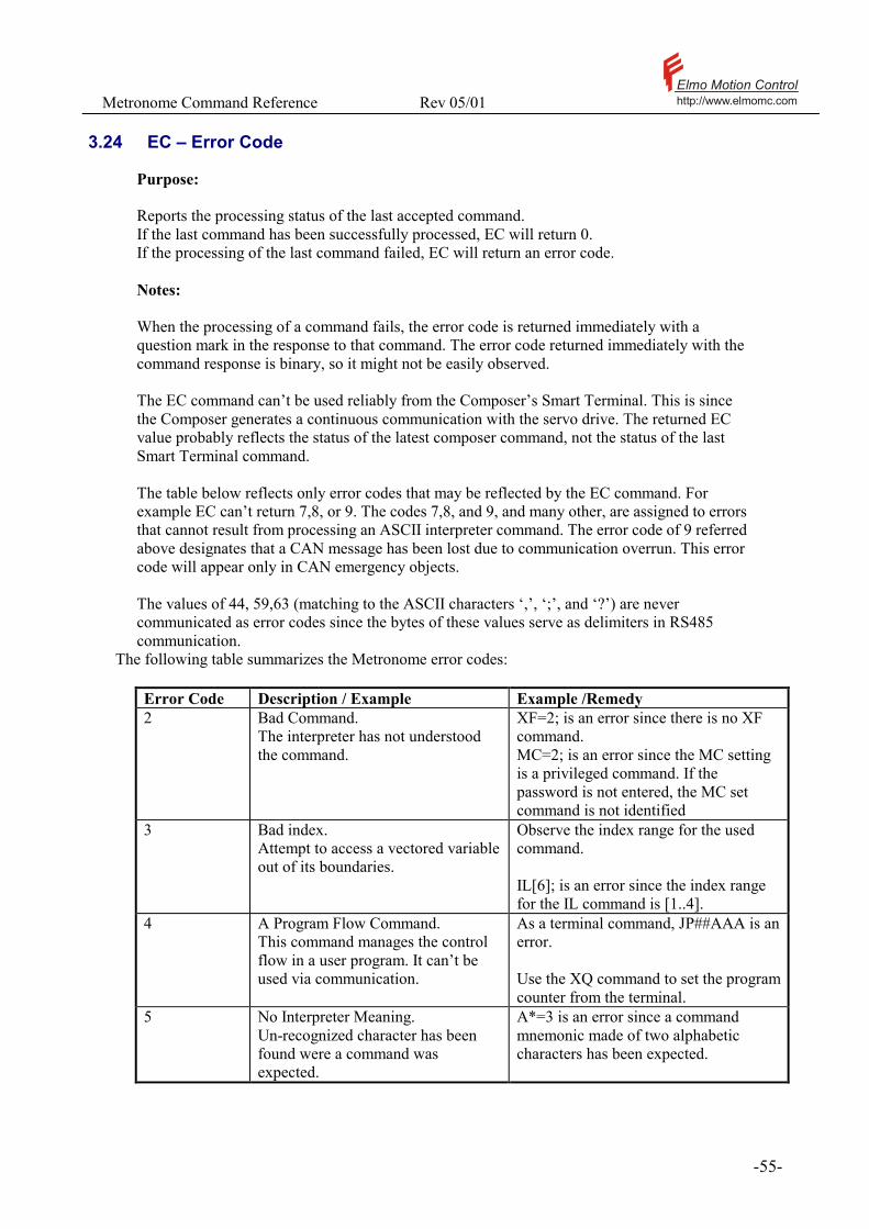
Metronome Command Reference Rev 05/01 Elmo Motion Controlhttp://www.elmomc.com
- 55 -
3.24 EC – Error Code
Purpose: Reports the processing status of the last accepted command. If the last command has been successfully processed, EC will return 0. If the processing of the last command failed, EC will return an error code. Notes: When the processing of a command fails, the error code is returned immediately with a question mark in the response to that command. The error code returned immediately with the command response is binary, so it might not be easily observed. The EC command can’t be used reliably from the Composer’s Smart Terminal. This is since the Composer generates a continuous communication with the servo drive. The returned EC value probably reflects the status of the latest composer command, not the status of the last Smart Terminal command. The table below reflects only error codes that may be reflected by the EC command. For example EC can’t return 7,8, or 9. The codes 7,8, and 9, and many other, are assigned to errors that cannot result from processing an ASCII interpreter command. The error code of 9 referred above designates that a CAN message has been lost due to communication overrun. This error code will appear only in CAN emergency objects. The values of 44, 59,63 (matching to the ASCII characters ‘,’, ‘;’, and ‘?’) are never communicated as error codes since the bytes of these values serve as delimiters in RS485 communication.
The following table summarizes the Metronome error codes:
Error Code Description / Example Example /Remedy 2 Bad Command.
The interpreter has not understood the command.
XF=2; is an error since there is no XF command. MC=2; is an error since the MC setting is a privileged command. If the password is not entered, the MC set command is not identified
3 Bad index. Attempt to access a vectored variable out of its boundaries.
Observe the index range for the used command. IL[6]; is an error since the index range for the IL command is [1..4].
4 A Program Flow Command. This command manages the control flow in a user program. It can’t be used via communication.
As a terminal command, JP##AAA is an error. Use the XQ command to set the program counter from the terminal.
5 No Interpreter Meaning. Un-recognized character has been found were a command was expected.
A*=3 is an error since a command mnemonic made of two alphabetic characters has been expected.

Metronome Command Reference Rev 05/01 Elmo Motion Controlhttp://www.elmomc.com
- 56 -
Error Code Description / Example Example /Remedy 6 Program is not running. MI return this error when called if the
program is not running, since the MI parameter will be automatically set to zero when the program starts.
12 Command not available in this unit mode.
PA=1000 is an error if UM=2, since in this mode the position cannot be commanded.
13 Cannot reset communication - UART is busy. An attempt to modify the parameters of the serial communication while the communication line is busy.
16 Collision of RS-485 messages. The Metronome tried to transmit a message, but characters have been destroyed by electrical interruption – probably the network master, or another servo drive tried to transmit on the RS485 lines at the same time.
Test that: No two servo drives in the network have the same ID. No more then one servo drive is defined as network representative. No more then one servo drive in a group is defined as a group representative Network time-outs are correctly set.
17 Sampling time is too short for the mode. Some modes use less CPU, so they can run with higher sampling rate. An attempt has been made to set a CPU consuming motion mode while TS is defined too low.
If UM=2 and the sampling time is set as the minimum for UM=2, attempting UM=4 will return this error.
18 Empty Assignment. The right side of an equation is missing.
AC=; is an error, since the interpreter expected a numerical value to appear after the ‘=’ sign.
19 Bad Command Format An unresolved syntax error in the command – please refer this manual for the correct command syntax.
20 Operand Error. Attempt to read a command that do not return a value.
21 Operand Out of Range. Attempt to assign an illegal value to a parameter.
JV=100000000 returns this error since the required speed is too large for the Metronome.
22 Zero Division. JV=0; IA[1]=1000/JV Will return this error.
23 Command Cannot Be Assigned. BG=3000 returns this error. BG is an execution command that do not have a value.
24 Bad operator. An un-recognized character has been found in an expression where an operator has been expected.
IA[1]=3$VX is an error since $ is not a recognized operator.
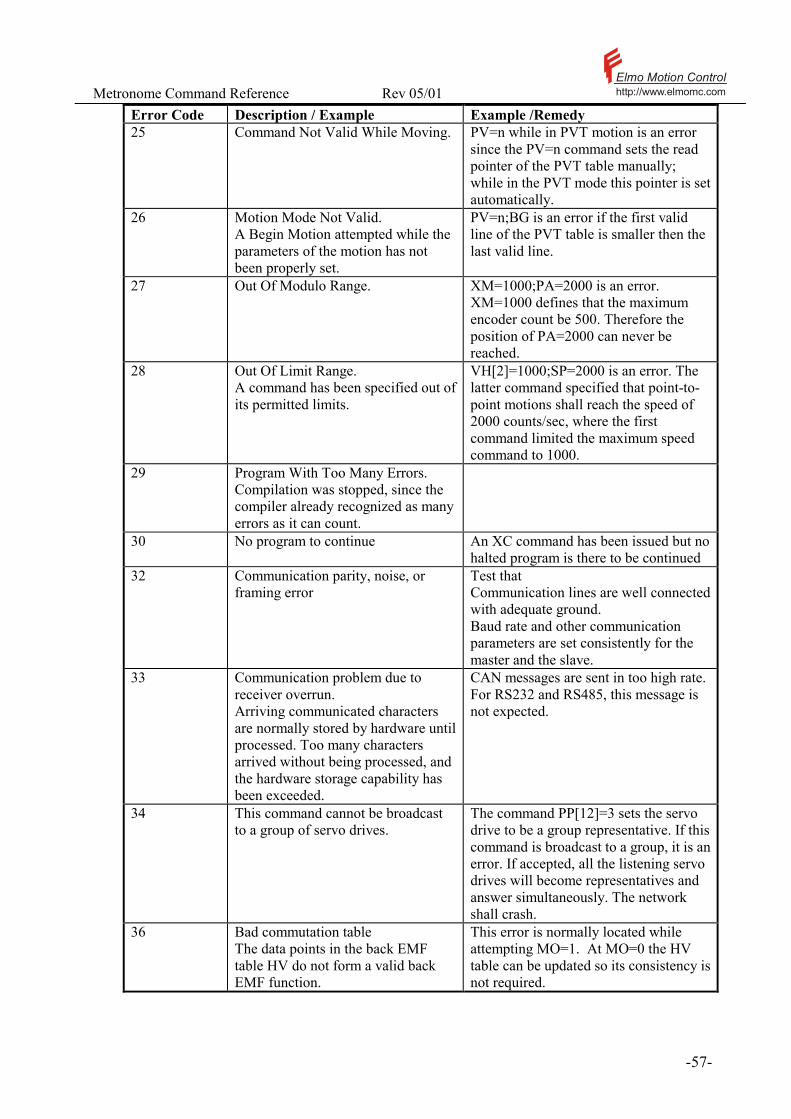
Metronome Command Reference Rev 05/01 Elmo Motion Controlhttp://www.elmomc.com
- 57 -
Error Code Description / Example Example /Remedy 25 Command Not Valid While Moving. PV=n while in PVT motion is an error
since the PV=n command sets the read pointer of the PVT table manually; while in the PVT mode this pointer is set automatically.
26 Motion Mode Not Valid. A Begin Motion attempted while the parameters of the motion has not been properly set.
PV=n;BG is an error if the first valid line of the PVT table is smaller then the last valid line.
27 Out Of Modulo Range.
XM=1000;PA=2000 is an error. XM=1000 defines that the maximum encoder count be 500. Therefore the position of PA=2000 can never be reached.
28 Out Of Limit Range. A command has been specified out of its permitted limits.
VH[2]=1000;SP=2000 is an error. The latter command specified that point-to-point motions shall reach the speed of 2000 counts/sec, where the first command limited the maximum speed command to 1000.
29 Program With Too Many Errors. Compilation was stopped, since the compiler already recognized as many errors as it can count.
30 No program to continue An XC command has been issued but no halted program is there to be continued
32 Communication parity, noise, or framing error
Test that Communication lines are well connected with adequate ground. Baud rate and other communication parameters are set consistently for the master and the slave.
33 Communication problem due to receiver overrun. Arriving communicated characters are normally stored by hardware until processed. Too many characters arrived without being processed, and the hardware storage capability has been exceeded.
CAN messages are sent in too high rate. For RS232 and RS485, this message is not expected.
34 This command cannot be broadcast to a group of servo drives.
The command PP[12]=3 sets the servo drive to be a group representative. If this command is broadcast to a group, it is an error. If accepted, all the listening servo drives will become representatives and answer simultaneously. The network shall crash.
36 Bad commutation table The data points in the back EMF table HV do not form a valid back EMF function.
This error is normally located while attempting MO=1. At MO=0 the HV table can be updated so its consistency is not required.

Metronome Command Reference Rev 05/01 Elmo Motion Controlhttp://www.elmomc.com
- 58 -
Error Code Description / Example Example /Remedy 37 Two or more Hall sensors are defined to
the same place. One of the following: CA[4]=CA[5], CA[4]=CA[6] or CA[5]=CA[6].
42 No Such Label. The program does not contain a label with the specified name.
XQ##FOO will return that error if the label ##FOO does not exist in the user program.
38 Different in HALL level Hall levels in Clarinet must be with the same level. Refer to CA[1] – CA[3].
46 Multiple homing feature can not be activated with ‘Stop After Event”
This error is caused when trying to set multiple capture events with STOP between the events. For example the following can not be set: HM[4]=0 ; HM[1]=3.
47 Program Not Compiled XQ shall return this error if no program had been loaded to the Metronome and successfully compiled.
50 Stack Overflow A CPU exception detected. This error reflects one of the following: A bug in the Metronome A hardware problem. A faulty power supply.
Please use CD to find out the details of what happened. If “Called handler” is “none” and “Failure address” is non-zero, then TS is too short and there was a real-time overflow. Please record the entire string of CD and call your service center for technical support.
51 Empty Program LS is an error if no program has been loaded to memory – nothing to list.
53 Only For Current. Command is applicable only in torque control modes UM=1 or 3.
TC=2 (Set torque to 2A) is an error in UM=2, since in this mode the torque command is set automatically by the controller so as to achieve the desired speed.
54 Bad Database. Cannot start the motor, as the setup data is not consistent.
If CA[4]==CA[5] then two physical Hall sensors are defined to be the same logical sensor. This inconsistency prevents powering the motor.
55 Bad Context. A command that is not applicable in the present context has been attempted.
This error is caused by privileged commands that are used in auto-setup sessions.
56 RM Must be Zero. A software reference has been attempted in modes where the reference signal is composed only from analog inputs.
For UM=1;RM=1, TC=1 is an error since the current command is measured at the analog input and not taken from the software.
57 Motor Must be Off. This command cannot be used when the motor is ON.
CA[25]=1 sets the order of firing the motor phases, thus controlling the motor direction. This parameter cant be set while the motor is ON, since it will immediately de-stabilize the feedback loop.
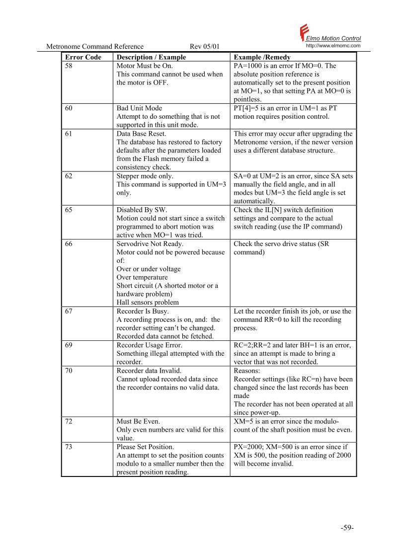
Metronome Command Reference Rev 05/01 Elmo Motion Controlhttp://www.elmomc.com
- 59 -
Error Code Description / Example Example /Remedy 58 Motor Must be On.
This command cannot be used when the motor is OFF.
PA=1000 is an error If MO=0. The absolute position reference is automatically set to the present position at MO=1, so that setting PA at MO=0 is pointless.
60 Bad Unit Mode Attempt to do something that is not supported in this unit mode.
PT[4]=5 is an error in UM=1 as PT motion requires position control.
61 Data Base Reset. The database has restored to factory defaults after the parameters loaded from the Flash memory failed a consistency check.
This error may occur after upgrading the Metronome version, if the newer version uses a different database structure.
62 Stepper mode only. This command is supported in UM=3 only.
SA=0 at UM=2 is an error, since SA sets manually the field angle, and in all modes but UM=3 the field angle is set automatically.
65 Disabled By SW. Motion could not start since a switch programmed to abort motion was active when MO=1 was tried.
Check the IL[N] switch definition settings and compare to the actual switch reading (use the IP command)
66 Servodrive Not Ready. Motor could not be powered because of: Over or under voltage Over temperature Short circuit (A shorted motor or a hardware problem) Hall sensors problem
Check the servo drive status (SR command)
67 Recorder Is Busy. A recording process is on, and: the recorder setting can’t be changed. Recorded data cannot be fetched.
Let the recorder finish its job, or use the command RR=0 to kill the recording process.
69 Recorder Usage Error. Something illegal attempted with the recorder.
RC=2;RR=2 and later BH=1 is an error, since an attempt is made to bring a vector that was not recorded.
70 Recorder data Invalid. Cannot upload recorded data since the recorder contains no valid data.
Reasons: Recorder settings (like RC=n) have been changed since the last records has been made The recorder has not been operated at all since power-up.
72 Must Be Even. Only even numbers are valid for this value.
XM=5 is an error since the modulo-count of the shaft position must be even.
73 Please Set Position. An attempt to set the position counts modulo to a smaller number then the present position reading.
PX=2000; XM=500 is an error since if XM is 500, the position reading of 2000 will become invalid.
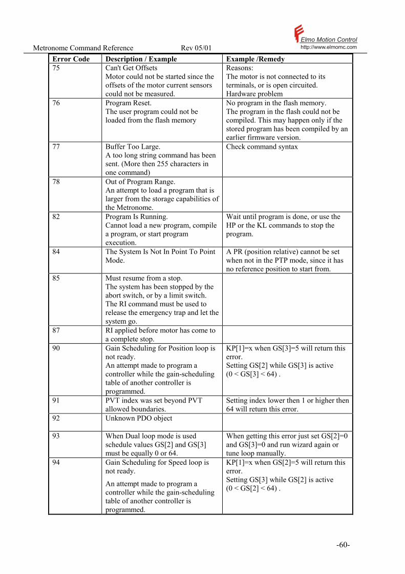
Metronome Command Reference Rev 05/01 Elmo Motion Controlhttp://www.elmomc.com
- 60 -
Error Code Description / Example Example /Remedy 75 Can't Get Offsets
Motor could not be started since the offsets of the motor current sensors could not be measured.
Reasons: The motor is not connected to its terminals, or is open circuited. Hardware problem
76 Program Reset. The user program could not be loaded from the flash memory
No program in the flash memory. The program in the flash could not be compiled. This may happen only if the stored program has been compiled by an earlier firmware version.
77 Buffer Too Large. A too long string command has been sent. (More then 255 characters in one command)
Check command syntax
78 Out of Program Range. An attempt to load a program that is larger from the storage capabilities of the Metronome.
82 Program Is Running. Cannot load a new program, compile a program, or start program execution.
Wait until program is done, or use the HP or the KL commands to stop the program.
84 The System Is Not In Point To Point Mode.
A PR (position relative) cannot be set when not in the PTP mode, since it has no reference position to start from.
85 Must resume from a stop. The system has been stopped by the abort switch, or by a limit switch. The RI command must be used to release the emergency trap and let the system go.
87 RI applied before motor has come to a complete stop.
90 Gain Scheduling for Position loop is not ready. An attempt made to program a controller while the gain-scheduling table of another controller is programmed.
KP[1]=x when GS[3]=5 will return this error. Setting GS[2] while GS[3] is active (0 < GS[3] < 64) .
91 PVT index was set beyond PVT allowed boundaries.
Setting index lower then 1 or higher then 64 will return this error.
92 Unknown PDO object
93 When Dual loop mode is used schedule values GS[2] and GS[3] must be equally 0 or 64.
When getting this error just set GS[2]=0 and GS[3]=0 and run wizard again or tune loop manually.
94 Gain Scheduling for Speed loop is not ready.
An attempt made to program a controller while the gain-scheduling table of another controller is programmed.
KP[1]=x when GS[2]=5 will return this error. Setting GS[3] while GS[2] is active (0 < GS[2] < 64) .
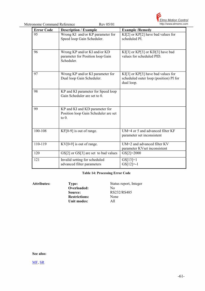
Metronome Command Reference Rev 05/01 Elmo Motion Controlhttp://www.elmomc.com
- 61 -
Error Code Description / Example Example /Remedy 95 Wrong KI and/or KP parameter for
Speed loop Gain Scheduler.
KI[2] or KP[2] have bad values for scheduled PI.
96 Wrong KP and/or KI and/or KD parameter for Position loop Gain Scheduler.
KI[3] or KP[3] or KD[3] have bad values for scheduled PID.
97 Wrong KP and/or KI parameter for Dual loop Gain Scheduler.
KI[3] or KP[3] have bad values for scheduled outer loop (position) PI for dual loop.
98 KP and KI parameter for Speed loop Gain Scheduler are set to 0.
99 KP and KI and KD parameter for Position loop Gain Scheduler are set to 0.
100-108 KF[0-9] is out of range.
UM=4 or 5 and advanced filter KF parameter set inconsistent
110-119 KV[0-9] is out of range. UM=2 and advanced filter KV parameter KVset inconsistent
120 GS[2] or GS[3] are set to bad values GS[2]=2000
121 Invalid setting for scheduled advanced filter parameters
GS[13]=1 GS[12]=-1
Table 14: Processing Error Code
Attributes: Type: Status report, Integer Overloaded: No Source: RS232/RS485 Restrictions: None Unit modes: All
See also: MF, SR
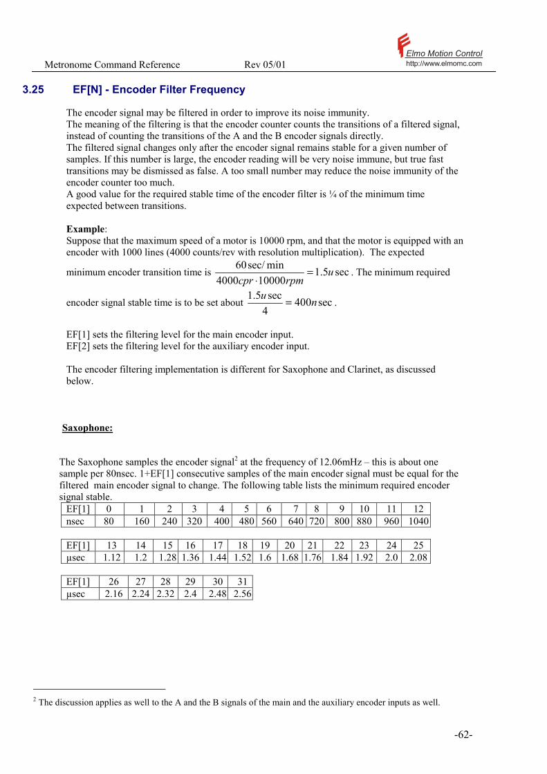
Metronome Command Reference Rev 05/01 Elmo Motion Controlhttp://www.elmomc.com
- 62 -
3.25 EF[N] - Encoder Filter Frequency
The encoder signal may be filtered in order to improve its noise immunity. The meaning of the filtering is that the encoder counter counts the transitions of a filtered signal, instead of counting the transitions of the A and the B encoder signals directly. The filtered signal changes only after the encoder signal remains stable for a given number of samples. If this number is large, the encoder reading will be very noise immune, but true fast transitions may be dismissed as false. A too small number may reduce the noise immunity of the encoder counter too much. A good value for the required stable time of the encoder filter is ¼ of the minimum time expected between transitions. Example: Suppose that the maximum speed of a motor is 10000 rpm, and that the motor is equipped with an encoder with 1000 lines (4000 counts/rev with resolution multiplication). The expected
minimum encoder transition time is sec5.1100004000
minsec/60 urpmcpr
=⋅
. The minimum required
encoder signal stable time is to be set about sec4004sec5.1 nu = .
EF[1] sets the filtering level for the main encoder input. EF[2] sets the filtering level for the auxiliary encoder input. The encoder filtering implementation is different for Saxophone and Clarinet, as discussed below.
Saxophone:
The Saxophone samples the encoder signal2 at the frequency of 12.06mHz – this is about one sample per 80nsec. 1+EF[1] consecutive samples of the main encoder signal must be equal for the filtered main encoder signal to change. The following table lists the minimum required encoder signal stable.
EF[1] 0 1 2 3 4 5 6 7 8 9 10 11 12 nsec 80 160 240 320 400 480 560 640 720 800 880 960 1040 EF[1] 13 14 15 16 17 18 19 20 21 22 23 24 25 µsec 1.12 1.2 1.28 1.36 1.44 1.52 1.6 1.68 1.76 1.84 1.92 2.0 2.08 EF[1] 26 27 28 29 30 31µsec 2.16 2.24 2.32 2.4 2.48 2.56
2 The discussion applies as well to the A and the B signals of the main and the auxiliary encoder inputs as well.
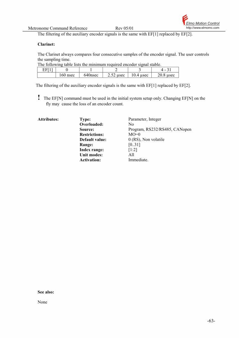
Metronome Command Reference Rev 05/01 Elmo Motion Controlhttp://www.elmomc.com
- 63 -
The filtering of the auxiliary encoder signals is the same with EF[1] replaced by EF[2]. Clarinet: The Clarinet always compares four consecutive samples of the encoder signal. The user controls the sampling time. The following table lists the minimum required encoder signal stable.
EF[1] 0 1 2 3 4 - 31 160 nsec 640nsec 2.52 µsec 10.4 µsec 20.8 µsec
The filtering of the auxiliary encoder signals is the same with EF[1] replaced by EF[2].
! The EF[N] command must be used in the initial system setup only. Changing EF[N] on the fly may cause the loss of an encoder count.
Attributes: Type: Parameter, Integer Overloaded: No Source: Program, RS232/RS485, CANopen Restrictions: MO=0 Default value: 0 (RS), Non volatile Range: [0..31] Index range: [1:2] Unit modes: All Activation: Immediate. See also: None

Metronome Command Reference Rev 05/01 Elmo Motion Controlhttp://www.elmomc.com
- 64 -
3.26 EM[N] – ECAM Parameters
Purpose: The EM[N] parameters determine the behavior of ECAM motions. ECAM is an acronym for “Electronic Cam”. It means that the position reference to the Metronome is not directly proportional to the summed external inputs, but is a function of them. Please refer the documentation of the RM command for an explanation of the position reference generation The ECAM related commands are as follows:
EM[1] Asserts whether the ECAM function is active.
1 for active ECAM. 0 for direct external referencing.
EM[2] The number of elements in the ECAM table. The used elements of the ECAM table are 1,2,…EM[2]. The maximum for EM[2] is 1024.
EM[3] Starting position – the value of the input to the ECAM function for which the output of the ECAM function will be ET[1]
EM[4] Table difference. When the input to the ECAM table will be EM[4], the ECAM function will output ET[2].When the input to the ECAM table will be 2*EM[4], the ECAM function will output ET[3], etc.
Attributes: Type: Parameter, Integer Overloaded: No Source: Program, RS232/RS485, CANopen Restrictions: MO=0 Default value: EM[1]=0,EM[2]=1,EM[3]=2,
EM[4]=1 (RS), Non volatile
Range: EM[1]: 0 or 1 EM[2]: [2..1024] EM[3]: Position range EM[4]: [1..32767]
Index range: [1:4] Unit modes: UM=4, UM=5 Activation: Immediate.
! The ECAM motion is described in detail in the software manual. See also: RM
Metronome Command Reference Rev 05/01 Elmo Motion Controlhttp://www.elmomc.com
- 65 -
3.27 EN - End Program Execution
Purpose: Ends program compiler directive. The EN “command” marks the end of the program for the compiler. It must appear at the bottom of the compiled code. The text beyond the EN directive is not compiled, and will not be executed by the program. Labels appearing after the EN directive are ignored. Examples: SP=1000; BG EN The above program includes the EN directive at its bottom, as required. The SP=1000 and the BG instructions shall be compiled. SP=1000; ##LOOP … JP##LOOP EN ** THIS IS AN OLDER VERSION MB=3 ##LOOP … JP##LOOP The above example shows an older version of the code is stored below the EN directive. The non-existent MB=3 command, and the second occurrence of the ##LOOP label will not generate any compilation or run time errors.

Metronome Command Reference Rev 05/01 Elmo Motion Controlhttp://www.elmomc.com
- 66 -
3.28 EO - Echo Mode
Purpose: Sets or resets the communication echo mode. The echo is used for communication check. EO=1 enables the echo mode while EO=0 disables it. EO is set to 1 at power on. With RS232 communication, The EO command sends an immediate echo character for every terminal character. With RS485, the echo cannot be sent immediately since the physical line is half duplex. The echo transmission is deferred to the command response string. Please refer the software manual. Setting EO to 0 to disable the echo. Attributes: Type: Parameter, Integer Overloaded: No Source: RS232/RS485 Restrictions: None Default value: 0, Volatile Range: 0 or 1 Unit modes: All Activation: Immediate See also: None
Metronome Command Reference Rev 05/01 Elmo Motion Controlhttp://www.elmomc.com
- 67 -
3.29 ER[N] - Maximum Tracking Error
Purpose: ER[2]- defines the maximum allowed velocity error in [counts/sec]. If the error exceeds this value, the motor is automatically disabled and the Error Limit fault is activated. ER[3]- defines the maximum allowed position error in [counts]. If the error exceeds this value, the motor is automatically disabled and the Error Limit fault is activated. Attributes: Type: Parameter, Integer Overloaded: No Source: Program, RS232/RS485, CANopen Restrictions: None Default value: ER[2] = 400000, ER[3]=2000 (RS), Non-volatile Range: [0..20000000] Index range 2 or 3 Unit modes: UM=2,5 for ER[2], UM=4,5 for ER[3] Activation: Immediate Typical applications: Decrease ER[N] as much as possible to use it as a protection mechanism in case of control failure, as when the feedback signal is lost. Examples: See also: MF, MO, SR

Metronome Command Reference Rev 05/01 Elmo Motion Controlhttp://www.elmomc.com
- 68 -
3.30 ET[N] – Entries for ECAM Table
Purpose: In the ECAM process, the position reference is set to a tabulated function, called the ECAM function, of the external inputs. The ET[N] vector stores the tabulated values of the ECAM function. Please refer the software manual for detailed description of ECAM motions.
Attributes: Type: Parameter, Integer Overloaded: No Source: Program, RS232/RS485, CANopen Restrictions: None Default value: 0 (RS), Non volatile Range: Not limited Index range [1 .. 1024] Unit modes: UM=4,5 Activation: Immediate See also: EM, UM, RM

Metronome Command Reference Rev 05/01 Elmo Motion Controlhttp://www.elmomc.com
- 69 -
3.31 FA - Floating Point Accuracy
Purpose: FA Defines the display accuracy of floating point numbers. FA=0 sets low accuracy (3 digits after the decimal point) and FA=1 to high accuracy. The FA value does not affect, in any way, the internal representation or calculations of the floating-point numbers; it merely controls the display of the values.
Attributes: Type: Parameter, Integer Overloaded: No Source: RS232/RS485 Restrictions: None Default value: 0, Volatile Range: 0 or 1 Unit modes: All Activation: Immediate You may need to set FA to 1 if you use small floating-point numbers. See also: None

Metronome Command Reference Rev 05/01 Elmo Motion Controlhttp://www.elmomc.com
- 70 -
3.32 FF – Feed Forward
Purpose: In UM=4, sets the movement ratio between the inner loop feedback device and the feedback device of the outer loop. The correct setting of FF is required for the construction of the speed reference to the inner loop from the derivative of the position reference to the outer loop. Please refer the software manual for details about dual loop control. Attributes: Type: Parameter, Real Overloaded: No Source: Program, RS232/RS485, CANopen Restrictions: None Default value: 1 (RS), Non volatile Range: Greater then 0. Unit modes: 4 Activation: Immediate Examples: Suppose that a gear motor with a reduction ratio of 5 drives a load. The motor has an encoder with 1000 lines. The motor speed is used for the inner feedback loop. The load position, measured by an encoder with 2000 lines, is used as feedback for the outer loop.
We have 4.051000
2000 =⋅
=FF .
See also: UM

Metronome Command Reference Rev 05/01 Elmo Motion Controlhttp://www.elmomc.com
- 71 -
3.33 FL – Fault Logic
Purpose: Setting the logic for the fault output. FL = 0 – Fault contact is “active high” – it opens upon a fault; no current will flow through the fault output. FL = 1 – Fault contact is “active low” – it closes upon a fault; current will flow through the fault output. Attributes: Type: Parameter, Integer Overloaded: No Source: Program, RS232/RS485, CANopen Restrictions: None Default value: FL = 0 (RS), Non-volatile. Range: FL (0:1) Unit modes: All
Typical applications: Adapting the amplifier to the error logic of external equipment. Arranging several amplifiers in interlocked fault connection. ! If several amplifiers are to be connected so that a failure of any of them activates the failure logic, there are two possible interlock connections: 1. Several active low fault outputs are connected in parallel 2. Several active high fault outputs are connected in series Sax has a low impedance reed relay for the fault output, so both types of interlock connections are practical. Clarinet has an opto-coupler fault output, so that fan-outs and voltages need be considered – please consult the Clarinet user manual. ! It is advised to use FL=0 (the factory default). This way, an un-powered amplifier automatically activates its fault logic. Examples: None. See also: IL

Metronome Command Reference Rev 05/01 Elmo Motion Controlhttp://www.elmomc.com
- 72 -
3.34 FR – Follower Ratio
Purpose: In UM=5, the auxiliary reference is composed of the analog inputs and the auxiliary encoder readout. The FR parameters scales the ratio between the auxiliary encoder readout and the reference to the position loop in UM=5. The way in which the FR command participates in the generation of the position reference is depicted in Figure 3.
Attributes: Type: Parameter, Real Overloaded: No Source: Program, RS232/RS485, CANopen Restrictions: MO=0 Default value: 1 (RS), Non volatile Range: [0..32767] Unit modes: 5 Activation: Immediate
! Take care that a modulo count of the auxiliary encoder will not generate discontinuous reference to the main position loop – please refer the YM command. See also: PY, RM, YM, YD
Metronome Command Reference Rev 05/01 Elmo Motion Controlhttp://www.elmomc.com
- 73 -
3.35 GS[N] – Gain Scheduling
Purpose: GS[N] Define the gain scheduling process:
• GS[0] specifies how many sampling times may elapse without any encoder count until the speed controller automatically drops its gain.
• GS[2] – For the speed controller. • GS[3] – For the position controller. • GS[4] – GS[8] Are internal factors of the gain scheduling process • GS[9] – Maximum allowed motor acceleration in internal units. • GS[10] – Internal factor for position loop scheduling. • GS[11] – Internal parameter for Dual loop controller. • GS[12] – GS[13]: Parameters for scheduler advanced filter settings.
GS[2]=0: The gains of the speed controller are locked. Entering the Metronome constants KP[2] and KI[2] will update the KI[2] and KP[2] parameters, as well as the constants that are available to the real time control process. GS[2]=N, 0<N< 64: The gains of the real time control process are locked – the Metronome gains will stay the same as they were at the last time where GS[2]=0 or GS[2]=64. Entering the Metronome constants KP[2] and KI[2] will update the Nth row of the speed controller gains table. The new entries of the gain table will not be applicable until the gain locking is released. GS[2]=64: Unlock gains. Real time gain scheduling of the speed controller takes place. GS[3]=0: The gains of the position controller are locked. Entering the Metronome constants KP[3], KD[3] and KI[3] will update the KP[3], KD[3] and KI[3] parameters, as well as the constants that are available to the real time control process. GS[3]=N, 0<N< 64: The gains of the real time control process are locked – the Metronome gains will stay the same as they were at the last time where GS[3]=0 or GS[3]=64. Entering the Metronome constants KP[3], KD[3] and KI[3] will update the Nth row of the position controller gains table. The new entries of the gain table will not be applicable until the gain locking is released. GS[3]=64: Unlock gains. Real time gain scheduling of the position controller takes place.
! The GS[N] array is normally programmed by the composer. PLEASE DO NOT deal with it unless you are sure what you are doing
! Please refer the software manual for a greater detail of the GS[N] array.

Metronome Command Reference Rev 05/01 Elmo Motion Controlhttp://www.elmomc.com
- 74 -
Attributes: Type: Parameter, Integer Overloaded: Yes Source: Program, RS232/RS485, CANopen Restrictions: MO=0 Default value: Non volatile Range: Not specified Unit modes: Speed, dual and position (2, 4 , and 5) Activation: Immediate See also: None
Metronome Command Reference Rev 05/01 Elmo Motion Controlhttp://www.elmomc.com
- 75 -
3.36 HL[N] – Over speed limit and position range limit
Purpose: The parameters LL[2] and HL[2] define the limits of the allowed motor speed. If the motor speed becomes higher then HL[2], or lower then LL[2], the motor is automatically disabled and the High Limit fault is activated (MF=20000H). If speed control is used (UM=2 or UM=5), always set the speed command limit VH[2] smaller then HL[2] and VL[2] greater then LL[2] with a sufficient margin for speed overshoots. If the motor is automatically shut down due to violation of HL[2], it is again possible to re-enable the motor when the speed shall drop below HL[2]. LL[3] and HL[3] define the allowed motor position range. If the motor position is smaller then LL[3] or larger then HL[3], the motor is automatically disabled and the High Limit fault (MF=400000H) is activated. If position control is used (UM=4 or UM=5), always set the position command limit VL[3] greater then LL[3], and also VH[3] smaller then HL[3], with a sufficient margin for stabilization overshoots. If the motor is automatically shut down due to violation of LL[3] or of HL[3], then the only way to re-enable the motor is to modify HL[3], LL[3], or PX.. Attributes: Type: Parameter, Integer Overloaded: No Source: Program, RS232/RS485, CANopen Restrictions: MO=0
Value of HL[2] and HL[3] must be higher then the correspond in LL[] value.
Default value: LL[2]=-1000000 HL[2]=1000000 LL[3]=-100000000 HL[3]=100000000 (RS), Non-volatile
Range: HL[2] - TS depended???? HL[3] - [-231 , 231 – 1]
Index range: 2 and 3 Unit modes: The speed limits apply to all the unit modes. The
position limits apply to UM= 4 and UM=5.
Activation: Immediate
Metronome Command Reference Rev 05/01 Elmo Motion Controlhttp://www.elmomc.com
- 76 -
Example: HL[2]=1000000;LL[2]=0; The motor is allowed to rotate up to 1000000 counts/sec in the positive direction. On the other hand, rotation in the negative direction is forbidden at all. In practice, it is not wise to limit the reverse speed to zero, since speed-readings in the order of few hundreds counts/sec may momentarily develop due to movements of one or two encoder counts. See also: VL, VH, MF, SR, MO, LL
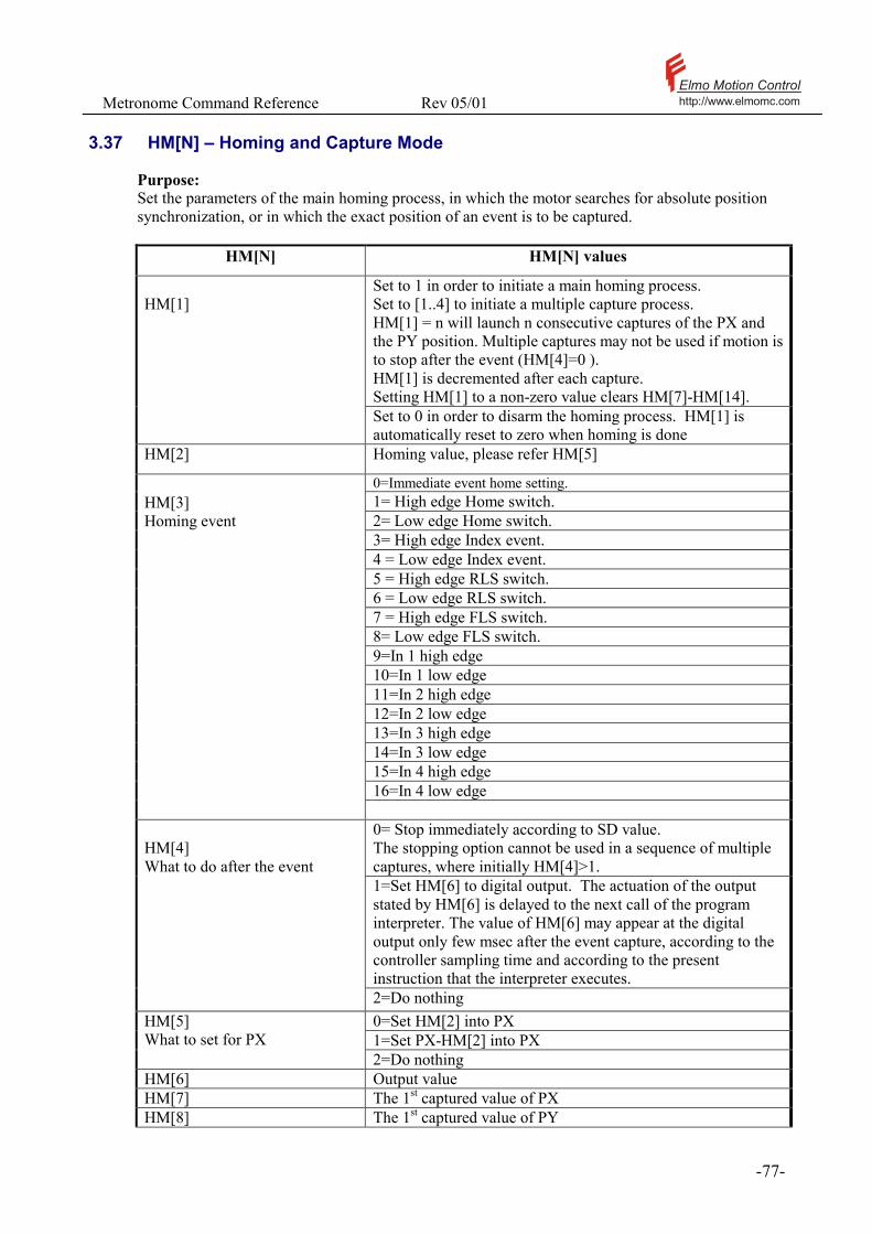
Metronome Command Reference Rev 05/01 Elmo Motion Controlhttp://www.elmomc.com
- 77 -
3.37 HM[N] – Homing and Capture Mode
Purpose: Set the parameters of the main homing process, in which the motor searches for absolute position synchronization, or in which the exact position of an event is to be captured.
HM[N] HM[N] values
Set to 1 in order to initiate a main homing process. Set to [1..4] to initiate a multiple capture process. HM[1] = n will launch n consecutive captures of the PX and the PY position. Multiple captures may not be used if motion is to stop after the event (HM[4]=0 ). HM[1] is decremented after each capture. Setting HM[1] to a non-zero value clears HM[7]-HM[14].
HM[1]
Set to 0 in order to disarm the homing process. HM[1] is automatically reset to zero when homing is done
HM[2] Homing value, please refer HM[5]
0=Immediate event home setting. 1= High edge Home switch. 2= Low edge Home switch. 3= High edge Index event. 4 = Low edge Index event. 5 = High edge RLS switch. 6 = Low edge RLS switch. 7 = High edge FLS switch. 8= Low edge FLS switch. 9=In 1 high edge 10=In 1 low edge 11=In 2 high edge 12=In 2 low edge 13=In 3 high edge 14=In 3 low edge 15=In 4 high edge 16=In 4 low edge
HM[3] Homing event
0= Stop immediately according to SD value. The stopping option cannot be used in a sequence of multiple captures, where initially HM[4]>1. 1=Set HM[6] to digital output. The actuation of the output stated by HM[6] is delayed to the next call of the program interpreter. The value of HM[6] may appear at the digital output only few msec after the event capture, according to the controller sampling time and according to the present instruction that the interpreter executes.
HM[4] What to do after the event
2=Do nothing 0=Set HM[2] into PX 1=Set PX-HM[2] into PX
HM[5] What to set for PX
2=Do nothing HM[6] Output value HM[7] The 1st captured value of PX HM[8] The 1st captured value of PY
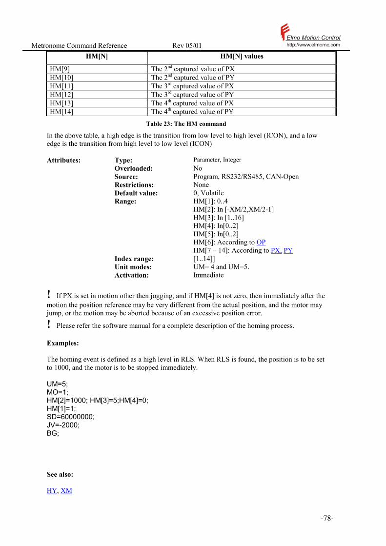
Metronome Command Reference Rev 05/01 Elmo Motion Controlhttp://www.elmomc.com
- 78 -
HM[N] HM[N] values
HM[9] The 2nd captured value of PX HM[10] The 2nd captured value of PY HM[11] The 3rd captured value of PX HM[12] The 3rd captured value of PY HM[13] The 4th captured value of PX HM[14] The 4th captured value of PY
Table 23: The HM command
In the above table, a high edge is the transition from low level to high level (ICON), and a low edge is the transition from high level to low level (ICON) Attributes: Type: Parameter, Integer Overloaded: No Source: Program, RS232/RS485, CAN-Open Restrictions: None Default value: 0, Volatile Range: HM[1]: 0..4
HM[2]: In [-XM/2,XM/2-1] HM[3]: In [1..16] HM[4]: In[0..2] HM[5]: In[0..2] HM[6]: According to OP HM[7 – 14]: According to PX, PY
Index range: [1..14]] Unit modes: UM= 4 and UM=5. Activation: Immediate
! If PX is set in motion other then jogging, and if HM[4] is not zero, then immediately after the motion the position reference may be very different from the actual position, and the motor may jump, or the motion may be aborted because of an excessive position error.
! Please refer the software manual for a complete description of the homing process. Examples: The homing event is defined as a high level in RLS. When RLS is found, the position is to be set to 1000, and the motor is to be stopped immediately. UM=5; MO=1; HM[2]=1000; HM[3]=5;HM[4]=0; HM[1]=1; SD=60000000; JV=-2000; BG; See also: HY, XM

Metronome Command Reference Rev 05/01 Elmo Motion Controlhttp://www.elmomc.com
- 79 -
3.38 HP - Halt Program Execution
Purpose: Halts the program. The HP command stops the execution of the user program and the automatic routines. The HP command freezes the status of the program, and does not reset it. A later XC command will resume the program from the instruction where the program was halted. Pending interrupts will remain pending. A HP command issued when no program is running does nothing, and sets no error code.
Attributes: Type: Command, No value Overloaded: No Source: RS232/RS485, CANopen Restrictions: None. Unit modes: All Activation: Immediate See also: KL, XQ, XC

Metronome Command Reference Rev 05/01 Elmo Motion Controlhttp://www.elmomc.com
- 80 -
3.39 HX - Hexadecimal Mode
Purpose: The HX parameter sets or resets the hexadecimal mode for reporting bit-field parameter values. With HX=0, bit-fields shall be reported as decimal numbers. With HX=1, bit-fields shall be reported as hexadecimal numbers. The HX parameter allows easy reading of the digital inputs (IP), servo drive status (SR), motor faults (MF), recorder settings (RC), and other variables that have the bit-field attribute. The HX parameter is not required to set bit-field values.
The commands BH=1024 and BH=400H are equivalent, as 400H equals 1024. Attributes: Type: Parameter, Integer Overloaded: No Source: RS232/RS485 Restrictions: None Default value: 0, Volatile Range: 0 or 1. Unit modes: All Activation: Immediate Example 1: The MF status inquiry returns a bit field, of which each bit is allocated to a possible motor fault reason. After the motor has been automatically shut down due to over speed, the MF status inquiry will read 131072 in the decimal (HX=0) mode, or more conveniently 20000H in the hexadecimal (HX=1) mode. Example 2: IP 323 HX=1;IP 143H HX=0 The second answer is much easier to analyze: input bits 1,2,7,9 are on, since 143 in hex is 1 0100 0011 binary.

Metronome Command Reference Rev 05/01 Elmo Motion Controlhttp://www.elmomc.com
- 81 -
3.40 HY[N] – Auxiliary Homing and Capture Mode
Purpose: Set the parameters of the auxiliary homing process, in which the main motor is set on an absolute position synchronization with the auxiliary feedback, or in which the exact position of an event is to be captured.
HY[N] HY[N] values
Set to 1 in order to initiate an auxiliary homing process. Set to [1..4] to initiate a multiple capture process. HY[1] = n will launch n consecutive captures of the PX and the PY position. Multiple captures may not be used if motion is to stop after the event (HY[4]=0 ). HY[1] is decremented after each capture. Setting HY[1] to a non-zero value clears HY[7]-HY[14].
HY[1]
Set to 0 in order to disarm the homing process. HY[1] is automatically reset to zero when homing is done
HY[2] Homing value, please refer HY[5]
0=Immediate event home setting. 1= High edge Home switch. 2= Low edge Home switch. 3= High edge Index event. 4 = Low edge Index event. 5 = High edge RLS switch. 6 = Low edge RLS switch. 7 = High edge FLS switch. 8= Low edge FLS switch. 9=In 1 high edge 10=In 1 low edge 11=In 2 high edge 12=In 2 low edge 13=In 3 high edge 14=In 3 low edge 15=In 4 high edge 16=In 4 low edge
HY[3] Homing event
0= Stop immediately according to SD value. Relevant only in dual loop mode (UM=4). The stopping option cannot be used in a sequence of multiple captures, where initially HY[4]>1. The actuation of the output stated by HY[6] is delayed to the next call of the program interpreter. The value of HY[6] may appear at the digital output only few msec after the event capture, according to the controller sampling time and according to the present instruction that the interpreter executes.
HY[4] What to do after the event
2=Do nothing 0=Set HY[2] into PY 1=Set PY-HY[2] into PY
HY[5] What to set for PY
2=Do nothing
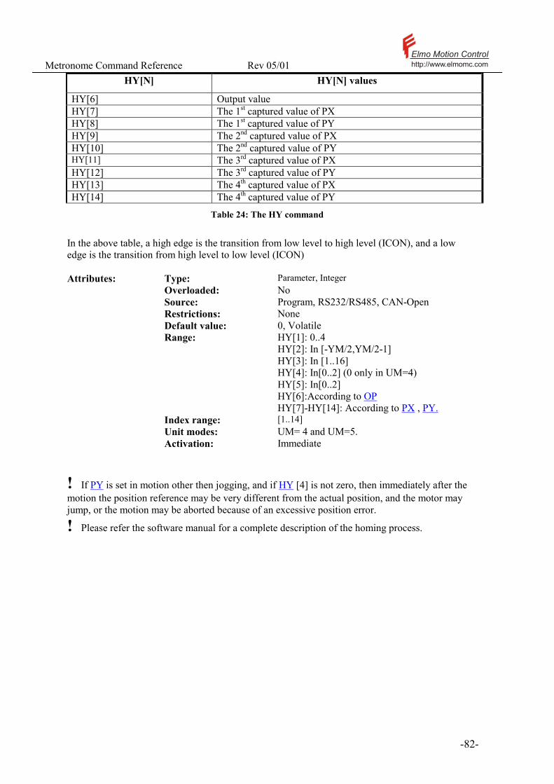
Metronome Command Reference Rev 05/01 Elmo Motion Controlhttp://www.elmomc.com
- 82 -
HY[N] HY[N] values
HY[6] Output value HY[7] The 1st captured value of PX HY[8] The 1st captured value of PY HY[9] The 2nd captured value of PX HY[10] The 2nd captured value of PY HY[11] The 3rd captured value of PX HY[12] The 3rd captured value of PY HY[13] The 4th captured value of PX HY[14] The 4th captured value of PY
Table 24: The HY command
In the above table, a high edge is the transition from low level to high level (ICON), and a low edge is the transition from high level to low level (ICON) Attributes: Type: Parameter, Integer Overloaded: No Source: Program, RS232/RS485, CAN-Open Restrictions: None Default value: 0, Volatile Range: HY[1]: 0..4
HY[2]: In [-YM/2,YM/2-1] HY[3]: In [1..16] HY[4]: In[0..2] (0 only in UM=4) HY[5]: In[0..2] HY[6]:According to OP HY[7]-HY[14]: According to PX , PY.
Index range: [1..14] Unit modes: UM= 4 and UM=5. Activation: Immediate
! If PY is set in motion other then jogging, and if HY [4] is not zero, then immediately after the motion the position reference may be very different from the actual position, and the motor may jump, or the motion may be aborted because of an excessive position error.
! Please refer the software manual for a complete description of the homing process.

Metronome Command Reference Rev 05/01 Elmo Motion Controlhttp://www.elmomc.com
- 83 -
Examples: The homing event is defined as a high level in RLS. When RLS is found, the PY position is to be set to 1000, the main motor will not stop and digital output will be set to 1. UM=5; MO=1; HY[2]=1000; HY[3]=5;HY[4]=1;HY[5]=0;HY[6]=1 HY[1]=1; SD=60000000; JV=-2000; BG; See also: HM, YM

Metronome Command Reference Rev 05/01 Elmo Motion Controlhttp://www.elmomc.com
- 84 -
3.41 IA[N] - Integer Array
Purpose: Provides an array of 100 integer numbers for general-purpose use.
Attributes: Type: Parameter, Integer Overloaded: No Source: Program, RS232/RS485, CANopen Restrictions: None Default value: 0, Volatile Range: Unlimited Index range: [0:99] Unit modes: All Activation: Immediate Typical applications: General, look-up tables of real numbers, parameters for machine task definition. Examples: MO=0; IA[1]=100; RA[IA[1]]=IA[2]*SP/IA[4]; In the above example, the RA array is dynamically indexed by an element of the IA array. See also: RA

Metronome Command Reference Rev 05/01 Elmo Motion Controlhttp://www.elmomc.com
- 85 -
3.42 IB[N] - Input Bits Array
Purpose: Provides access to individual general purpose and dedicated digital input bits. The polarity of the RLS,FLS and the Abort inputs is according to the LL setting. IB[N] reports the status of corresponding input bit, according to the table below.
N Meaning
1…4 General Purpose Input 5…8 Reserved
9 Main Home (Sax Only) 10 Auxiliary Home 11 Forward Limit (FLS) 12 Reverse Limit (RLS) 13 Abort switch 14 Enable switch
Table 25: Inputs Bits Array Values
The IB[N] may be more convenient then IP for Program decisions and branching. The IB[N] is, however, not good for synchronized reading of several input bits. If a synchronized reading of several digital inputs is desired, use the IP command.
Attributes: Type: Status report, Integer Overloaded: No Source: RS232/RS485, CANopen , Program Restrictions: None Unit modes: All
See also: IP, LL, OP, OB[N]

Metronome Command Reference Rev 05/01 Elmo Motion Controlhttp://www.elmomc.com
- 86 -
3.43 ID,IQ – Read the Active current and the Reactive current (SAX Only)
Purpose: Get the Active and the Reactive components of the motor current in Amperes. A three-phased motor has two independent phase currents. The first two-phase currents determine the current of the third phase, as the sum of all the three phase currents must be zero. Vector-control servo drives do not control the phase currents directly, as the phase currents vary according to the motor shaft angle. The fast variations of the phase currents make them hard to control. It is easier to control the so-called active and reactive components of the phase currents.
(Active current) [ ])240cos()120cos()cos(32 °+⋅+°+⋅+⋅= θθθ IcIbIaIQ
(Reactive current) [ ])330cos()210cos()90cos(32 °+⋅+°+⋅++⋅= θθθ IcIbIaI D
�
Where Ia , Ib , and )( IbIaIc +−= are the phase currents. The motor generates torque that is directly proportional to QI . The servo drive tries to stabilize
QI so as to produce the required torque.
The component DI has no effect of the motor torque. The servo drive tries to reduce DI to zero.
A measure of the servo drive efficiency is 22
)cos(DQ
Q
II
I
+=φ .
The active current QI [Amp] may be read by the command IQ, the reactive current DI [Amp] may be read by the command ID, and the phase currents Ia [Amp] and Ib [Amp] may be read using AN[1] and AN[2].
! The reported currents are in the RMS sense. This means that for IQ=1[Amp], ID=0[Amp], the maximum Ia (at 0=θ ) and of Ib (at �120=θ ) will be 1.414 [Amp].
Attributes: Type: Status report, Real Overloaded: No Source: RS232/RS485,CANopen , Program Restrictions: None Unit modes: All See also: AN, AM, MC, PL[N], CL[N]
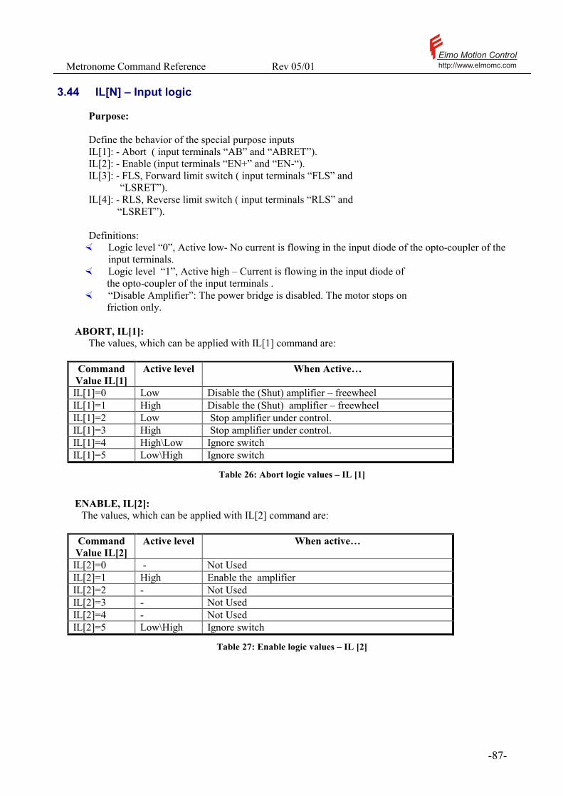
Metronome Command Reference Rev 05/01 Elmo Motion Controlhttp://www.elmomc.com
- 87 -
3.44 IL[N] – Input logic
Purpose: Define the behavior of the special purpose inputs IL[1]: - Abort ( input terminals “AB” and “ABRET”). IL[2]: - Enable (input terminals “EN+” and “EN-“). IL[3]: - FLS, Forward limit switch ( input terminals “FLS” and “LSRET”). IL[4]: - RLS, Reverse limit switch ( input terminals “RLS” and “LSRET”). Definitions: �� Logic level “0”, Active low- No current is flowing in the input diode of the opto-coupler of the
input terminals. �� Logic level “1”, Active high – Current is flowing in the input diode of the opto-coupler of the input terminals . �� “Disable Amplifier”: The power bridge is disabled. The motor stops on friction only.
ABORT, IL[1]: The values, which can be applied with IL[1] command are:
Command Value IL[1]
Active level When Active…
IL[1]=0 Low Disable the (Shut) amplifier – freewheel IL[1]=1 High Disable the (Shut) amplifier – freewheel IL[1]=2 Low Stop amplifier under control. IL[1]=3 High Stop amplifier under control. IL[1]=4 High\Low Ignore switch IL[1]=5 Low\High Ignore switch
Table 26: Abort logic values – IL [1]
ENABLE, IL[2]:
The values, which can be applied with IL[2] command are:
Command Value IL[2]
Active level When active…
IL[2]=0 - Not Used IL[2]=1 High Enable the amplifier IL[2]=2 - Not Used IL[2]=3 - Not Used IL[2]=4 - Not Used IL[2]=5 Low\High Ignore switch
Table 27: Enable logic values – IL [2]
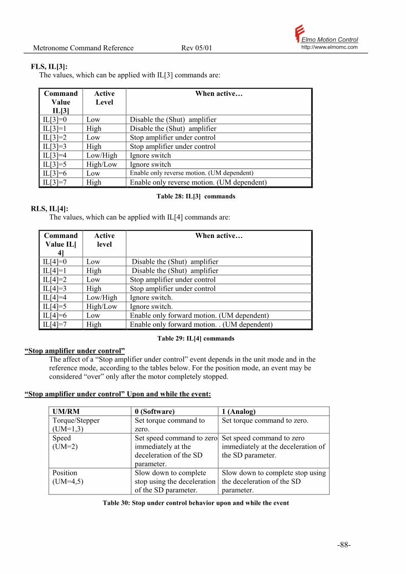
Metronome Command Reference Rev 05/01 Elmo Motion Controlhttp://www.elmomc.com
- 88 -
FLS, IL[3]:
The values, which can be applied with IL[3] commands are:
Command Value IL[3]
Active Level
When active…
IL[3]=0 Low Disable the (Shut) amplifier IL[3]=1 High Disable the (Shut) amplifier IL[3]=2 Low Stop amplifier under control IL[3]=3 High Stop amplifier under control IL[3]=4 Low/High Ignore switch IL[3]=5 High/Low Ignore switch IL[3]=6 Low Enable only reverse motion. (UM dependent) IL[3]=7 High Enable only reverse motion. (UM dependent)
Table 28: IL[3] commands
RLS, IL[4]: The values, which can be applied with IL[4] commands are:
Command Value IL[
4]
Active level
When active…
IL[4]=0 Low Disable the (Shut) amplifier IL[4]=1 High Disable the (Shut) amplifier IL[4]=2 Low Stop amplifier under control IL[4]=3 High Stop amplifier under control IL[4]=4 Low/High Ignore switch. IL[4]=5 High/Low Ignore switch. IL[4]=6 Low Enable only forward motion. (UM dependent) IL[4]=7 High Enable only forward motion. . (UM dependent)
Table 29: IL[4] commands
“Stop amplifier under control” The affect of a “Stop amplifier under control” event depends in the unit mode and in the reference mode, according to the tables below. For the position mode, an event may be considered “over” only after the motor completely stopped.
“Stop amplifier under control” Upon and while the event:
UM/RM 0 (Software) 1 (Analog) Torque/Stepper (UM=1,3)
Set torque command to zero.
Set torque command to zero.
Speed (UM=2)
Set speed command to zero immediately at the deceleration of the SD parameter.
Set speed command to zero immediately at the deceleration of the SD parameter.
Position (UM=4,5)
Slow down to complete stop using the deceleration of the SD parameter.
Slow down to complete stop using the deceleration of the SD parameter.
Table 30: Stop under control behavior upon and while the event

Metronome Command Reference Rev 05/01 Elmo Motion Controlhttp://www.elmomc.com
- 89 -
“Event is over” Event is over is defined as: - The switch is released. Note: For UM=4 and UM=5 in analog mode, RI command must be set.
“Stop amplifier under control” After the event is over;
UM/RM 0 (Software) 1 (Analog) Torque/Stepper (UM=1,3)
Torque returns to set TC value.
Torque follows analog command.
Speed (UM=2)
The motor will accelerate to the value set JV.
Speed follows analog command.
Position (UM=4,5)
Position remains in place, new position motions may be commanded using BG.
May resume operation after setting RI command, in this case position follows analog command3 and any software position mode may be started using the BG command.
Table 31: Stop under control behavior after the event is over
“Enable one direction only” The effect of an “Enable one direction only” event depends in the unit mode and in the reference mode, as listed in the tables below.
“Event is over”
Event is over is defined as: - The switch is released. Note: For UM=4 and UM=5: - In software mode, switch must be released (or logic changed) - In analog mode, switch must be released (or logic changed) and RI command must be set.
“Enable one direction only” Upon and while the event
UM Event Action Torque/Stepper (UM=1,3)
(RLS/FLS) is sensed. Set torque command to zero The torque is disabled in both directions.
Speed (UM=2)
(RLS/FLS) is sensed with (Negative/Positive) speed command. The motion is disabled in one direction only. Motion to the opposite direction is enabled.
Set speed command to zero immediately. The motion is disabled in one direction only. Motion to the opposite direction is enabled.
Position (UM=4,5)
(RLS/FLS) is sensed. .
Slow down to complete stop using the deceleration of the SD parameter.
Table 32: Stop under control behavior upon and while the event
3 The analog command upon RI is adjusted to the current position – motor will not jump even if current command was changed during switch event.
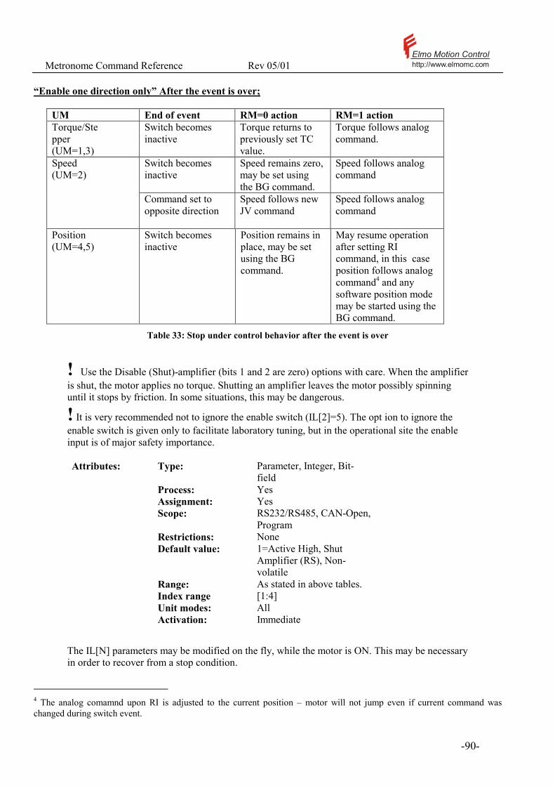
Metronome Command Reference Rev 05/01 Elmo Motion Controlhttp://www.elmomc.com
- 90 -
“Enable one direction only” After the event is over;
UM End of event RM=0 action RM=1 action Torque/Stepper (UM=1,3)
Switch becomes inactive
Torque returns to previously set TC value.
Torque follows analog command.
Switch becomes inactive
Speed remains zero, may be set using the BG command.
Speed follows analog command
Speed (UM=2)
Command set to opposite direction
Speed follows new JV command
Speed follows analog command
Position (UM=4,5)
Switch becomes inactive
Position remains in place, may be set using the BG command.
May resume operation after setting RI command, in this case position follows analog command4 and any software position mode may be started using the BG command.
Table 33: Stop under control behavior after the event is over
! Use the Disable (Shut)-amplifier (bits 1 and 2 are zero) options with care. When the amplifier is shut, the motor applies no torque. Shutting an amplifier leaves the motor possibly spinning until it stops by friction. In some situations, this may be dangerous.
! It is very recommended not to ignore the enable switch (IL[2]=5). The opt�ion to ignore the enable switch is given only to facilitate laboratory tuning, but in the operational site the enable input is of major safety importance. Attributes: Type: Parameter, Integer, Bit-
field Process: Yes Assignment: Yes Scope: RS232/RS485, CAN-Open,
Program Restrictions: None Default value: 1=Active High, Shut
Amplifier (RS), Non-volatile
Range: As stated in above tables. Index range [1:4] Unit modes: All Activation: Immediate
The IL[N] parameters may be modified on the fly, while the motor is ON. This may be necessary in order to recover from a stop condition.
4 The analog comamnd upon RI is adjusted to the current position – motor will not jump even if current command was changed during switch event.

Metronome Command Reference Rev 05/01 Elmo Motion Controlhttp://www.elmomc.com
- 91 -
Examples: IL[4]=6 defines that the reverse limit switch is active low. When a low value is read in the reverse limit switch, only forward motion is allowed. See also:

Metronome Command Reference Rev 05/01 Elmo Motion Controlhttp://www.elmomc.com
- 92 -
UM, RM, RI, JV, PX, BG
Metronome Command Reference Rev 05/01 Elmo Motion Controlhttp://www.elmomc.com
- 93 -
3.45 IM – Motor current (Clarinet only)
Purpose: IM reads the motor current in Amperes. IM reads the actual measured motor current, NOT the current command to the amplifier. Attributes: Type: Status report, Real Overloaded: No Source: RS232/RS485, CANopen, Program Restrictions: None Unit modes: All See also: AN, AM, MC, PL[N], CL[N]
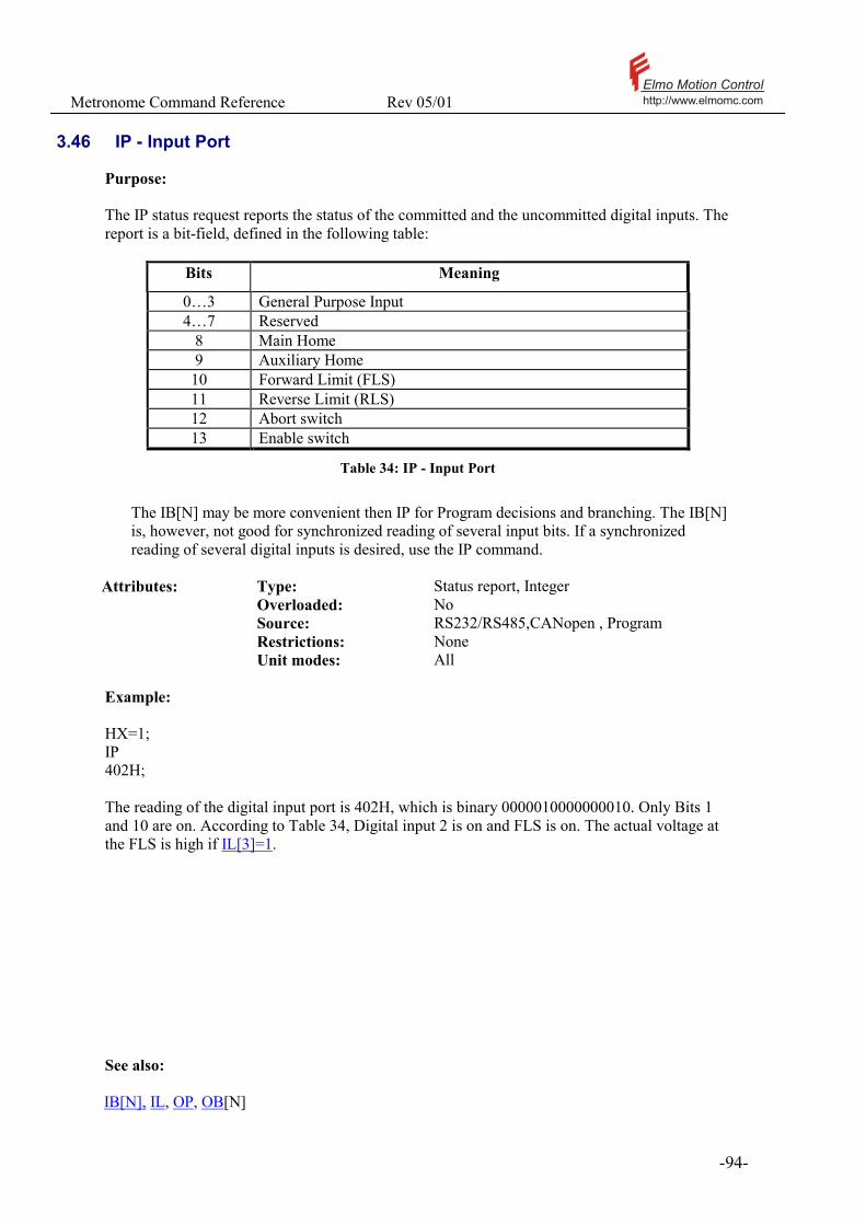
Metronome Command Reference Rev 05/01 Elmo Motion Controlhttp://www.elmomc.com
- 94 -
3.46 IP - Input Port
Purpose: The IP status request reports the status of the committed and the uncommitted digital inputs. The report is a bit-field, defined in the following table:
Bits Meaning
0…3 General Purpose Input 4…7 Reserved
8 Main Home 9 Auxiliary Home 10 Forward Limit (FLS) 11 Reverse Limit (RLS) 12 Abort switch 13 Enable switch
Table 34: IP - Input Port
The IB[N] may be more convenient then IP for Program decisions and branching. The IB[N] is, however, not good for synchronized reading of several input bits. If a synchronized reading of several digital inputs is desired, use the IP command.
Attributes: Type: Status report, Integer Overloaded: No Source: RS232/RS485,CANopen , Program Restrictions: None Unit modes: All Example: HX=1; IP 402H; The reading of the digital input port is 402H, which is binary 0000010000000010. Only Bits 1 and 10 are on. According to Table 34, Digital input 2 is on and FLS is on. The actual voltage at the FLS is high if IL[3]=1. See also: IB[N], IL, OP, OB[N]

Metronome Command Reference Rev 05/01 Elmo Motion Controlhttp://www.elmomc.com
- 95 -
3.47 JP - Jump (Conditionally)
Purpose: Jump to a specified label with an optional condition. A jump loads a label anywhere in the program to the program counter. Labels always start with ## or #@. Attributes: Type: Command, String Overloaded: No Source: Program Restrictions: None. Unit modes: All Activation: Immediate Syntax:
Syntax Operation
JP<LABEL1> Jump to the label LABEL1 JP<LABEL1>,<CONDITION>
Jump to the label LABEL1, only if the condition is true
Examples: ##LOOP PA=500; … AC=100; JP##LOOP,PX<0 SP=1000; In the example above, after the instruction AC=100 is executed, the Metronome tests PX. If PX<0, the next executed instruction is PA=500. Otherwise the next executed instruction is SP=1000. ##LOOP PA=500; … AC=100; JP##LOOP SP=1000; In the second example, the next executed instruction after AC=100 is PA=500, unconditionally. See also: JS, JZ, AF

Metronome Command Reference Rev 05/01 Elmo Motion Controlhttp://www.elmomc.com
- 96 -
3.48 JS - Jump (Call) To Subroutine
Purpose: Jumps (calls) to a specified subroutine with an optional condition. A subroutine is a piece of code that may be called from anywhere in the program. For executing a subroutine, the present value of the program counter is stored in the call stack, and then the program counter is set to the specified subroutine. The subroutine return (RT command) restores the program counter so that program execution will resume immediately after the subroutine call. The subroutine call may be conditioned, in which case the subroutine will be called only if the condition is true.
Attributes: Type: Command, String Overloaded: No Source: Program Restrictions: None. Unit modes: All Activation: Immediate
Syntax:
Syntax Operation
JS<LABEL1> Jump to a subroutine at the label LABEL1 JS<LABEL1>,<CONDITION> Jump to a subroutine at the label LABEL1, only if the
condition is true
Examples:
##MAIN_LOOP JS#@INIT ##LOOP JS#@FOO JS#@TASK,IB3=1 JP##LOOP ** MAIN TASK UNCONDITIONAL SUBROUTINE #@FOO .. RT ** MAIN TASK CONDITIONAL SUBROUTINE #@TASK ........ RT ** INITIALIZTION SUBROUTINE #@INIT ........ RT In the above example, a very simple infinite main loop references (calls) detailed subroutines, written somewhere else. The subroutine #@FOO is executed unconditionally. The subroutine #@TASK is executed only if input bit 3 is on.

Metronome Command Reference Rev 05/01 Elmo Motion Controlhttp://www.elmomc.com
- 97 -
3.49 JV - Jogging Velocity
Purpose: Set the motor speed. In the speed control mode (UM=2), the parameter JV specifies the software (RM=0) speed command. In the un-profiled mode (PM=0), the speed command is set to JV immediately. In the profiled mode (PM=1) the speed command is gradually changed to JV, according to the AC, DC, and SF parameters. In the position control modes (UM=4,5) the setting of JV defines a constant speed software command. The value of JV defines the speed of the motion. The parameters AC, DC, and SF determine the profile of reaching the final speed. In the position-jogging mode, a position-controlled motor can rotate forever. Its position reading will jump each time it crosses the counter modulo border ( 302 at most), but the speed shall remain steady.
Notes:
• The Jog mode is used for homing procedures. • In the position mode, a jogging command is under position control. The JV
parameter determines the rate at which the position-command changes. • In the position control mode (UM=4,5), JV not only sets the speed of motion. It
also states that the next motion shall be a constant speed jog. • The value of JV must be set between VL[2] and VH[2]. Setting JV out of this
range invokes the “Out of limit” error code. Attributes: Type: Parameter, Integer Overloaded: No Source: Program, RS232/RS485, CANopen Restrictions: UM=2: None
UM=5: MO=1 Default value: 0 (RS), Non-volatile.
The stored value applies only to UM=2 Range: [0, 8000000] (Sax)
[0, 1500000] (Clarinet) Unit modes: UM=2,4,5 Activation: BG Examples: MO=0;UM=5;MO=1;JV=10000;BG Starts a position controlled jogging motion. MO=0;UM=5;JV=10000 Is illegal. MO=0;UM=2;JV=10000;MO=1;BG Starts a speed controlled jogging motion. See also: AC, BG, DC, PX, XM, YM, SF SP, VH[N], VL[N], MS

Metronome Command Reference Rev 05/01 Elmo Motion Controlhttp://www.elmomc.com
- 98 -
3.50 JZ - Jump And Zero Stack
Purpose: The JZ command jumps to a label, while clearing the program call stack. Each time a subroutine, or an automatic routine is called, the program counter is set to the starting label of that routine. In order that the RT return command of the routine is able to resume the program execution, the Metronome has to remember the value of the program counter when the routine was called. Upon routine calls, the Metronome stores the value of the Program Counter as a return address in the call stack. Many return addresses may be stored in the call stack if nested subroutines are called. If a jump desired from within a subroutine to a label, and program execution is not to resume from the place where the program has been called from, then the call stack must be cleared5 by using the JZ command.
Attributes: Type: Command, String Overloaded: No Source: Program Restrictions: None. Unit modes: All Activation: Immediate
Examples: IA[1]=0 ##START MO=1 ... ... YOUR PROGRAM ... #@AUTO_ER MG AT AUTO_ER JZ##START RT
This code assures that the program is reset to its starting label in the case of error, regardless of the call stack condition when the error occurred. See also: JS, JP, RT, #@, AF
5 Unused return addresses in the call stack cause no harm, but if not cleared, they consume storage place. This may cause the call stack to overflow.

Metronome Command Reference Rev 05/01 Elmo Motion Controlhttp://www.elmomc.com
- 99 -
3.51 KD[N], KI[N], KP[N] - PI Parameters
Purpose: KI[1], KP[1] - Defines the PI current control filter. SAX Only KI[2], KP[2] - Defines the PI velocity control filter. KD[3] – Defines the derivative gain for the position controller. KI[3], KP[3] - Defines the PI position control filter. Please refer the software manual for detailed explanation.
Attributes: Type: Parameter. Overloaded: No Source: Program and communication Restrictions: None. Default values: RS: KD[3]: 0.0
KI[2]: 45.0 KI[3]: 0.0 KP[1]: 0.95 KP[2]: 0.5
KP[3]: 0.0 Range: Index number: [1, 3] , integer
Returned value: KD: [0, ∞] , real KI: [0, ∞] , real KP: [0, ∞] , real
See also: KF[N]
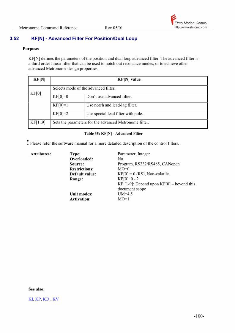
Metronome Command Reference Rev 05/01 Elmo Motion Controlhttp://www.elmomc.com
- 100 -
3.52 KF[N] - Advanced Filter For Position/Dual Loop
Purpose:
KF[N] defines the parameters of the position and dual loop advanced filter. The advanced filter is a third order linear filter that can be used to notch out resonance modes, or to achieve other advanced Metronome design properties.
KF[N] KF[N] value
Selects mode of the advanced filter.
KF[0]=0 Don’t use advanced filter.
KF[0]=1 Use notch and lead-lag filter.
KF[0]
KF[0]=2 Use special lead filter with pole.
KF[1..9] Sets the parameters for the advanced Metronome filter.
Table 35: KF[N] - Advanced Filter
! Please refer the software manual for a more detailed description of the control filters. Attributes: Type: Parameter, Integer Overloaded: No Source: Program, RS232/RS485, CANopen Restrictions: MO=0 Default value: KF[0] = 0 (RS), Non-volatile. Range: KF[0]: 0 - 2
KF [1-9]: Depend upon KF[0] – beyond this document scope
Unit modes: UM=4,5 Activation: MO=1
See also: KI, KP, KD , KV
Metronome Command Reference Rev 05/01 Elmo Motion Controlhttp://www.elmomc.com
- 101 -
3.53 KL - Kill Motion And Program
Purpose: Halts program execution and stop the motor. The KL command stops the execution of the user program and the automatic routines. It also issues the MO=0 motor disable command. The KL command freezes the status of the program, and does not reset it. A later XC command will resume the program from the instruction where the program was halted. Pending interrupts will remain pending. A KL command issued when no program is running does nothing, and sets no error code. Attributes: Type: Command, No value Overloaded: No Source: RS232/RS485, CANopen Restrictions: None. Unit modes: All Activation: Immediate
! If the motor was on when KL was used, then using XC to continue the program may fail. This is since the program that has been interrupted expects the motor to be on, and it may use commands that are restricted to the MO=1 state. In this case, the program may be continued by typing MO=1;XC. See also: HP,XQ, XC

Metronome Command Reference Rev 05/01 Elmo Motion Controlhttp://www.elmomc.com
- 102 -
3.54 KV[N] - Advanced Filter For Speed Loop
Purpose: KV[N] defines the parameters of the speed loop advanced filter. The advanced filter is a third order linear filter that can be used to notch out resonance modes, or to achieve other advanced Metronome design properties.
KV[N] KV[N] value
Selects mode of the advanced filter.
KV[0]=0 Don’t use advanced filter.
KV[0]=1 Use notch and lead-lag filter.
KV[0]
KV[0]=2 Use special lead filter with pole.
KV[1..9] Sets the parameters for the advanced Metronome filter.
Table 36: KV[N] - Advanced Filter
! Please refer the software manual for a more detailed description of the control filters. Attributes: Type: Parameter, Integer Overloaded: No Source: Program, RS232/RS485, CANopen Restrictions: MO=0 Default value: KV[0] = 0 (RS), Non-volatile. Range: KV[0]: 0 - 2
KV [1-9]: Depend upon KV[0] – beyond this document scope
Unit modes: UM=2 Activation: MO=1
See also: KI, KP, KD , KF

Metronome Command Reference Rev 05/01 Elmo Motion Controlhttp://www.elmomc.com
- 103 -
3.55 LC - Current Limit Flag
Purpose: LC reports the status of the current limiting process. The user may select two different current limit specifications. The peak limit PL[1] specifies how much current can be applied to the motor for short times. The continuous limit CL[1] specifies how much current can be applied to the motor continuously. For a detailed description of the current limiting process, please refer the documentation of the PL command. LC returns values according to the following table:
Value Description 0 The motor current is limited to the peak limit PL[1], or the motor is off. 1 The motor current is limited to the continuous limit CL[1] Attributes: Type: Status report, Integer Overloaded: No Scope: Program, RS232/RS485, CANopen Restrictions: None Unit modes: All
See also: MC, PL[N], CL[N]
Metronome Command Reference Rev 05/01 Elmo Motion Controlhttp://www.elmomc.com
- 104 -
3.56 LD - Load Parameters From FLASH
Purpose:
The LD command loads all the non-volatile variables from the Flash memory to the RAM and resets all the volatile variables to their default value. Before accepting the loaded parameters, LD tests them as follows:
• The variables written in the flash memory can be read. The variables can’t be read only if the flash memory is brand new and nobody ever saved parameters in it.
• The software version matches. Major firmware updates may modify the nature of some stored variables. In that case, the parameters in the flash cannot be retrieved.
• The variables in the flash memory are all in their permitted range. This test should never fail, as the legality of all the variables is tested prior to saving.
If any of the above tests fails, then the contents of the flash memory are ignored, and all the non-volatile variables are set to their factory default (RS) state. There are few exceptional variables that are not reset by the LD command.
• The RS232/RS485 communication (PP) parameters are retrieved from the flash memory, but are not set into action. The parameter PP[1] retains its old values. This is done so in order to assure communication continuity. The newly loaded communication parameters may be activated by assigning a value to PP[1].
• The digital outputs are not changed, for safety The LD command does not affect the user program – please refer the CP, LG, and the SG commands.
! The analog output is reset to zero by the LD command.
!The LD command may take few msec to perform, since it completely re-calculates the Metronome database. At this time, the communication routines are disabled. If an LD command is executed by an RS232/RS485 command, in the meanwhile a CAN message may be lost, and vice versa.
! LD does not change the communication settings, so after executing LD, it is still possible to communicate with the Metronome. The communication parameters are however changed to their flash-stored values. The RS232/485 communication will become active after the next setting of PP[1], and the parameters of the CAN communication will become active in the next network-start NMT command.
Attributes: Type: Command, No value Overloaded: No Source: Program, RS232/RS485, CANopen Restrictions: MO=0, Program is not running Unit modes: All Activation: Immediate
See also:
SV, RS

Metronome Command Reference Rev 05/01 Elmo Motion Controlhttp://www.elmomc.com
- 105 -
3.57 LG - Load User Program
Purpose: LG Retrieves the user program from the flash (non-volatile) memory to the volatile memory (RAM). The DL command downloads a program to the Metronome. The Metronome stores the program temporarily in a volatile memory. The program is executed from the volatile memory (RAM), but it will be erased the next time power is shut down. The SG command may be used to store the program already downloaded to the Metronome in the non-volatile (Flash) memory. An LG command loads a program that was stored in the flash memory to the RAM and compiles it, to be ready for execution. In the Metronome boot process, the Metronome checks the existence of a program in the non-volatile memory. If a program exists there, it is automatically makes it ready for use by performing the LD command.
Attributes: Type: Command, No value Overloaded: No Source: RS232/RS485, CANopen Restrictions: MO=0,Program not running. Unit modes: All Activation: Immediate
See also: SG, DL, CC

Metronome Command Reference Rev 05/01 Elmo Motion Controlhttp://www.elmomc.com
- 106 -
3.58 LL[N] - Low Actual Feedback Limit
Purpose: The parameters LL[2] and HL[2] define the limits of the allowed motor speed. For details please refer the HL command. Attributes: Type: Parameter, Integer Overloaded: No Source: Program, RS232/RS485, CANopen Restrictions: MO=0 Default value: LL[2]=-1000000
LL[3]=-100000000 (RS), Non-volatile
Range: Unlimited Index range: 2 and 3 Unit modes: The speed limits apply to all the unit modes. The
position limits apply to UM= 4 and UM=5.
Activation: Immediate Example: Please refer the HL[N] command See also: VL[N], VH, MF, SR, MO, HL[N]

Metronome Command Reference Rev 05/01 Elmo Motion Controlhttp://www.elmomc.com
- 107 -
3.59 LP - List Properties
Purpose: Set the properties of the program segment uploaded by the next LS command.
• LP[1] sets the number for the first program line to be transmitted. • LP[2] sets the number for the last program line to be transmitted. • LP[3] is a read only parameter – it states the number of program lines.
Any program downloading, either from the flash memory or by the DL command, sets LP[3] automatically to the largest line number. It also sets LP[1]=1, LP[2]=LP[3], and If no program is not loaded, LP[1], LP[2], and LP3] shall return 0.
Attributes: Type: Parameter, Integer Overloaded: No Process: Yes Assignment: Yes (PL[1] and PL[2] only) Scope: Program, RS232/RS485, CANopen Restrictions: LP[1] ≤ LP[2] ≤ LP[3] Default value: 0, Volatile Index Range: [1:3] Unit modes: All Activation: Immediate Example: Consider the program MO=0; SP=1000;AC=2000; DC=1; MO=1; With LP[1]=2 and LP[2]=3. The command LS Will return SP=1000;AC=2000; DC=1;(0x8) Where (0x8) denotes the non printable character 8. LP[3] will return 4.
See also: CC, DL, LS
Metronome Command Reference Rev 05/01 Elmo Motion Controlhttp://www.elmomc.com
- 108 -
3.60 LS - List User Program
Purpose: Upload the user program to the host, according to the parameters of LP. The first sent line by the next LS command is LP[1]. The last sent line by the next LS command is LP[2]. If the program lines LP[1] to LP[2] contains more then 1000 characters, the LS command will fail and issue an error code.
! The string returned by the LS command is terminated by the non-printable character 0x8, not by ‘;’. Please note that the string LS returns is a program segment which may include many ‘;’ and <CR> characters. The 0x8 character at the end of the string makes the end of transmission identifiable.
! Use the LS command with care. The LS command is not entirely safe in the sense that while the program listing is uploading to the communication lines, no program instructions are executed, and no interpreting of communicated commands takes place. An executing LS command can be interrupted only by a CANopen NMT command.
Attributes: Type: Command, No value Overloaded: No Source: RS232/RS485 Restrictions: Program loaded. Unit modes: All Activation: Immediate Example:
Consider the program MO=0; SP=1000;AC=2000; DC=10000; MO=1; With LP[1]=2 and LP[2]=3. The command LS Will return SP=1000;AC=2000; DC=10000;(0x8) Where (0x8) denotes the non printable character 8.
See also: CC, DL, LP
Metronome Command Reference Rev 05/01 Elmo Motion Controlhttp://www.elmomc.com
- 109 -
3.61 MC – Maximum Peak Driver Current
Purpose:
Reports the maximum peak driver current in [Amperes]. This command informs the software about the type of servo drive that is used with the Metronome. This variable is set at the factory and should be left unchanged. The commands IQ, ID, IM, CL[N], and PL[N] use this value to report the motor current and to perform the over-current protection algorithm. The MC parameter is not changed by a software reset (RS) command. The MC parameter may be changed only after entering a password.
Attributes: Type: Parameter, Real Overloaded: No Scope: Program, RS232/RS485, CANopen Restrictions: MO=0, Write access protected by a password. Default value: Peak driver current, Non-volatile.
The stored value applies only to UM=2 Range: [0, 100] Unit modes: All Activation: Immediate
See also: IQ, ID, IM, CL PL, RS
Metronome Command Reference Rev 05/01 Elmo Motion Controlhttp://www.elmomc.com
- 110 -
3.62 MF - Motor Failure
Purpose: MF reports the reason why the motor has been automatically shut down (set to MO=0). The fact that the motor has been automatically shut down is reflected in the status register (SR) report. MF gives the details. The following table lists the type of faults, which are reported by the MF value:
Reported fault Value Bit
The motor is on, or the last motor shut down has been the normal result of a software command.
0
Main encoder error. This can only happen if the A and the B channels switched simultaneously. The reason may be heavy noise on the encoder line, or too large time delay in the encoder filter (Too big EF[1] value).
1H 0
Auxiliary encoder error. This can only happen if the A and the B channels switched simultaneously. The reason may be heavy noise on the encoder line, or too large time delay in the encoder filter (Too big EF[2] value).
2H 1
Feedback loss - no match between encoder and HALL location. 4H 2 The peak current has been exceeded. Possible reasons are:
• Amplifier malfunction. •••• For digital current servo drives like Saxophone: the
current controller is not tuned.
8H 3
External inhibit – An abort condition of the input logic (IL command) has been met.
10H 4
Digital hardware failure. 20H 5 Two digital Hall sensors had been changed at the same time. This is an error since the digital Hall sensors must change one at a time.
40H 6
The speed tracking error DV[2]-VX exceeded the speed error limit ER[2]. This may happen in UM=2 or UM=5 due to: -Bad tuning of the speed controller -Too tight speed error tolerance -The motor cant accelerate to the required speed because of too low line voltage, or the motor is not powerful enough.
80H 7
The position tracking error DV[3]-PX (UM=5) or DV[3]-PY (UM=4) exceeded the position error limit ER[3]. This may happen due to: -Bad tuning of the position (UM=4 or 5) or the speed (UM=4) controller -Too tight speed error tolerance -Abnormal motor load, or a mechanical limit has been reached.
100H 8
Cannot start because of inconsistent database. The type of database inconsistency is reflected in the status SR report, and in the CD CPU dump report.
200H 9
Not used 400H 10 Life guarding failure. This error occurs if the Metronome is set to operate under life guarding in a CANopen network, in UM1 or UM=3, and the life guarding process times out without verification of the host presence.
800H 11
Metronome Command Reference Rev 05/01 Elmo Motion Controlhttp://www.elmomc.com
- 111 -
Reported fault Value Bit
Servo drive fault. One of the following has happened, according to the servo drive- fault detail bits 13-15 in the MF report. Please refer Error! Reference source not found.
1000H 12
Servo drive-fault detail bit 1. Please refer Error! Reference source not found.
2000H 13
Servo drive-fault detail bit 2. Please refer Error! Reference source not found.
4000H 14
Servo drive-fault detail bit 3. Please refer Error! Reference source not found.
8000H 15
Failed to find the electrical zero of the motor in an attempt to start a motor with an incremental encoder and no digital Hall sensors. The reason may be that the applied motor current did not suffice to move the motor from its place.
10000H 16
Speed limit exceeded: VX<LL[2] or VX>HL[2]. 20000H 17 Stack overflow. This may happen if the CPU had been subject to a load it can’t handle. Possible reasons are:
• Too low sampling time • Too high rate of high priority motion reference PDO
(CANopen) messages. Please use the CD command to get the CPU dump and report to your service center.
40000H 18
CPU exception. An unhappy situation, like an attempt to divide in zero, or other fatal firmware error. Please use the CD command to get the CPU dump and report to your service center.
80000H 19
Programmable logic exception. Again, a sad situation, most probably a hardware fault. Please use the CD command to get the CPU dump and report to your service center.
100000H 20
Motor is powered but is not moving. 200000H 21 Position limit exceeded: PX<LL[3] or PX>HL[3] (UM=5), or PY<LL[3] or PY>HL[3] (UM=4).
400000H 22
Cannot tune the current offsets. A part of the process of motor starting (MO=1) is the calibration of A/D and D/A offsets. This process may fail if the motor is not well connected to the servo drive, or as the result of hardware malfunction.
10000000H 28
Table 37: Reasons for automatic motor shut down

Metronome Command Reference Rev 05/01 Elmo Motion Controlhttp://www.elmomc.com
- 112 -
The interpretation of bits 12-15 of the MF report is detailed in the table below.
8000H 4000H 2000H Meaning
0 0 0 O.k. 0 0 1 Under voltage – the power supply is shut down, or it has too
high impedance. 0 1 0 Over voltage. The voltage of the power supply is too large, or
the servo drive did not succeed in absorbing the kinetic energy while breaking a load. For a Clarinet servo drive, which does not have an internal shunt resistor, maybe a shunt resistor needs to be added.
0 1 1 SVP – Internal power supply is too low. This voltage is lower then the ‘under voltage’ range and may appear in conjunction with it. In these cases SVP will appear instead of ‘under voltage’.
1 0 1 Short circuit. The motor or its wiring may be defective.
1 1 0 Temperature. Amplifier overheating. The environment is too hot, or bad heat removal. Possible reasons: Blocked air inlet or faulty fan (Saxophone) Large thermal resistance between the amplifier and its mounting (Clarinet).
1 1 1 Commutation – Since the Metronome perform the commutation internally this message is not likely to appear. Value of 7 will usually be the conjunction of SVP and ‘External Disable’. External Disable is being set at motor off.
Table 38: Servo drive failures report detail
Attributes: Type: Status report, Integer, Bit-field Scope: Program, RS232/RS485, CANopen Restrictions: None Unit modes: All
Example The MF report of 3000H tells that the motor has been shut down due to under-voltage. The under voltage condition not necessarily exists at the time when MF is reported. Possibly the under-voltage was the result of large power consumption and a high output impedance of the power supply. In that case, when the motor was shut down the power consumption stopped and the power supply returned to its normal voltage. See also: SR, MO, TS, LL, HL[N], RI, CD, PE, VE
Metronome Command Reference Rev 05/01 Elmo Motion Controlhttp://www.elmomc.com
- 113 -
3.63 MG – Send Message
Purpose: The MG command sends a message (string) to the host. The message may include any text but the instruction terminators ‘;’ and <CR>. In order to state a line break in the text, use the ‘&’ character which is interpreted as a line break. The message generated by the MG command cannot be sent immediately to the host, since in order to prevent communication crashes, the host must synchronize all the RS232/RS485 communication from Metronome to the host. The Metronome stores the message, and does not send it. The host may retrieve the message using the MZ command. Up to 50 messages may be stored. If an attempt to save more then 50 messages is made without retrieving them, the older messages will remain, and the newer messages shall be lost. Attributes: Type: Command, String Overloaded: No Process: Yes Scope: Program Restrictions: None Unit modes: All Activation: Immediate Examples: MGPROCESS LONGER THAN 2 SEC&TN=2000; Will store the message PROCESS LONGER THAN 2 SEC TN=2000 For retrieval using the MZ command. See also: MZ

Metronome Command Reference Rev 05/01 Elmo Motion Controlhttp://www.elmomc.com
- 114 -
3.64 MI – Mask Interrupt
Purpose: The MI command selects which interrupts (automatic routines) are active. A user program may include a main code and some automatic routines. When a program runs, the conditions for calling the automatic routines are checked continuously. If the conditions6 for running an automatic routine are met, the automatic routine is called. The user may desire that at certain times some of the automatic routines be blocked. For example,
- An #@AUTO_RLS automatic routine may be deactivated in a homing process - It may be desired that a certain code sequence be un-interruptible. - Some auto-routines may are desired only when starting the program from certain labels. The MI command may then be used to block the un-desired automatic routines, according to the table below. MI value Masked interrupt Relevant routine 1 (0x1) Abort AUTO_ER 2 (0x2) RLS AUTO_RLS 4 (0x4) FLS AUTO_FLS 8 (0x8) Digital Input 1 AUTO_I1 16 (0x10) Digital Input 2 AUTO_I2 32 (0x20) Digital Input 3 AUTO_I3 64 (0x40) Digital Input 4 AUTO_I4
Notes:
• MI is set automatically to zero by the XQ command. It is possible to use the MI command from the communication interface only when a program is running.
• The MI command may be used at the first instruction of a program to safely block an automatic routine.
• The MI command may be safely used as the first instruction of an automatic routine. No other program instruction shall be executed from the time of interrupt condition checking and until the first two instructions of the automatic routine are completed.
• Several interrupts may be blocked by the MI command. MI=511 or MI=1ffh will block all the interrupts of the table. MI=6 will block only the AUTO_FLS and the AUTO_RLS interrupts. MI=MI|1 will block AUTO_ER, and leave all the other interrupt mask bits as is.
• Interrupts that occur while blocked by the MI instruction are ignored, and are not set in the pending list. The MI instruction does not, however, remove anything from the pending list. If an interrupt request has been pending at the time MI was called and blocked it, this request will remain active and execute when it is unmasked again.
6 The conditions include that no interrupt request of higher priority is pending (in which case the corresponding automatic routine enters the pending list), and that the interrupt is not masked (in which case the interrupt is ignored)

Metronome Command Reference Rev 05/01 Elmo Motion Controlhttp://www.elmomc.com
- 115 -
Attributes: Type: Parameter, Integer, Bit-field Overloaded: No Process: Yes Assignment: Yes Scope: Program, RS232/RS485, CANopen Restrictions: Program is running Default value: 0, Volatile Range: [0..511] Unit modes: All Activation: Immediate
Examples: @#AUTO_RLS ** WHEN EVER RLS IS SENSED OP=1 ; ** SET DIGITAL OUPUT 1 WT 500 ;** WAIT FOR 500 MSECS OP=0 ;** DIGITAL OUTPUT 0 RT UM=5 ;** POSITION LOOP FOR JOGGING MI=2; ** MASK THE RLS INTERRUPT. WILL NOT BRANCH TO AUTO ROUTINE MO=1;** MOTOR ON JV=10000; ** JOG 10000 CNT/SEC BG ; AF,IP&2048=1;** UNTIL RLS IS SENSED ST;** STOP MOTION MI=0 ;** RELEASE RLS INTERRUPT MASKING. JV=-JV; ** REVERSE DIRECTION BG The code of this example will issue a 500msec pulse at the digital output every time that RLS is sensed, from the second time at which RLS is met. See also: XQ, XC, #@AUTO_
Metronome Command Reference Rev 05/01 Elmo Motion Controlhttp://www.elmomc.com
- 116 -
3.65 MO - Motor Enable/Disable
Purpose: Start the motor, stop the motor, or enter simulation mode. MO=0 is the idle state of the servo drive. The power stage is disabled and current does not flow in the motor. In this mode, the servo drive can do various tasks that are unsafe or impossible to do when the motor is on: • Boot upon power up. • Modify setup data and the unit mode (UM) and calculate the database. • Store firmware, user programs, and parameters in the flash memory. If a fatal error is trapped, the servo drive automatically resets to MO=0. An attempt to change the state of MO=0 may fail if the conditions to enable the power stage are not fully met. MO=1 is the operative state of the servo drive. In the MO=1 state, the servo drive drives the motor and motions can be programmed and executed. When MO is set to 1, the software runs a set of tests to assure that all the conditions to start the motor are met. If the database is invalid (The database is invalid after power up, and any change of the unit mode or of the commutation parameters invalidates the database), the database is recalculated and its integrity is tested. If there is no absolute commutation sensor (A resolver or digital Hall sensors), Then after the database is recalculated, the electrical angle of the motor is invalidated. As a result, the motor shall perform a commutation search. The supply voltage and the offsets of the current measurement sensors are measured. The motor is always started so that it will not jump. In the torque unit-modes (UM=1 and UM=3), the torque command is set to zero. In the software speed unit mode (UM=2,RM=0) the speed command is set to zero. In the software position modes (UM=4 and UM=5, RM=0) the position command is set to the present motor position. In the external reference position modes (UM=4 and UM=5, RM=1) the external command is measured and the software position command is set so that its sum with the external command will be the present motor position. MO=-1 is a simulation state. In this state, the servo drive is disabled, but the reference generation mechanisms work as usual. The simulation mode is intended for testing and demonstrations.
Metronome Command Reference Rev 05/01 Elmo Motion Controlhttp://www.elmomc.com
- 117 -
Attributes: Type:
Command/Parameter, Integer
Source: Program, RS232/RS485, CANopen Restrictions: None Default value: 0, Volatile Range: 0,1,or –1 Unit modes: All Activation: Immediate
! The MO=1 command may take tens of milliseconds to perform if a database recalculation is required. Additional few tens of milliseconds may be required if a commutation search is performed.
!In the torque or the speed control analog reference (UM=1 or UM=2, and RM=1), the servo drive will attempt to start (set MO=1) automatically after power-on. A servo drive that has been shut down by any reason will attempt an automatic restart every few milliseconds. In all the other modes, the MO=0 state is maintained until MO is explicitly changed by a software command. Example 1: RM=1;UM=5;MO=1;PA=0;BG The first three commands start the motor in the external-reference position-control mode. After MO=1, the external reference is applied incrementally. In order to make the external reference absolute, a PTP motion to the software position of 0 is initialized. Example 2: The sequence CA[4]=1;CA[5]=1;MO=1 Attempts to start the motor after specifying the same position to two different digital Hall sensors. This inconsistency prevents the calculation of the database, and the command MO=1 will fail. The failure reason may be found using the SR or the CD command. See also: MF, SR, CD
Metronome Command Reference Rev 05/01 Elmo Motion Controlhttp://www.elmomc.com
- 118 -
3.66 MP[N] Motion Parameters (PT/PVT Parameters)
Purpose: Program the parameters of PVT or of PT motions. In the PT and PVT motion, the motion plan is programmed as a sequence of points that are visited at programmed times – please refer the software manual for a detailed description of the PT and the PVT motion modes. The QP[] array stores the positions reference points that are used for PT or PVT motions. The QV[], and the QT[] arrays store the speed and timing data that is additionally required for PVT motions. The entries of the QP, QV, and QT arrays that are used for a certain motion may be programmed. This enables to use a part of an array for running the motion, while another part of the array is programmed for the next motions. Moreover, the QP,QV and QT arrays may be referred as cyclical buffers. In the cyclical mode, periodic motions can be set to run forever. In addition, the host may program the table on the fly, generating an infinite, on-line updated motion. The MP[N] array defines how the QP,QV, and QT tables are used for PVT/PT motions, as detailed in the table below.
MP[1] The first index in the QP, QV, and QT arrays to be used for the motion. MP[2] The last index in the QP, QV, and QT arrays to be used for the motion. MP[3] • 0 if the motion is to terminate after the last (MP[2] ) element of the QP,
QV, and QT arrays is used. A PT or a PVT motion terminates by decelerating the motor to a complete stop, using the SD deceleration; an emergency object (when using CAN) will be transmitted.
• 1 if the motion is to be cyclical, so that after using the last (MP[2]) element of the QP, QV, and QT arrays, the first (MP[1]) element is used again.
• 2 When using CAN the motion is terminated without emergency object MP[4] MP[4] is used for PT motions only.
The number of Metronome sampling times between consecutive specifications of position reference points. Note that MP[4] counts sampling times for the position controller, which for the Saxophone is not equal to TS. The sampling time of the position controller is given by WS[29].
MP[5] If CANopen communications are used, it is possible that the Metronome shall send an emergency object to the host when only a predefined number of valid reference points has been left in the motion arrays QP,QV, and QT. In that way, the host is released from polling the Metronome continuously for the motion queue. MP[5] programs the number of valid motion points that are remained when an emergency object is sent to the host. If MP[5]=0, no emergency object is sent.
MP[6] MP[6] reports the number of the most recently programmed element in the motion tables. This report is required for running PVT and PT motions using CANopen and special high speed motion referencing methods that are available only for CANopen communication. Please refer the software manual.

Metronome Command Reference Rev 05/01 Elmo Motion Controlhttp://www.elmomc.com
- 119 -
Attributes: Type: Parameter, Integer Source: Program, RS232/RS485, CANopen Restrictions: None Default value: MP[1]=1,MP[2]=64,MP[3]=1,
MP[4]=4,MP[5]=50,MP[6]=1,Volatile Volatile
Range: 1 ≤ MP[1] < MP[2] ≤ 64 (PVT) 1 ≤ MP[1] < MP[2] ≤ 1024 (PT) MP[2]-MP[1] ≥ 2 (PVT) MP[3] = [0..2] MP[4] = [1..256] MP[5] < MP[2]-MP[1] MP[1] ≤ MP[6] ≤ MP[2]
Index range [1..6] Unit modes: Position control: UM=4 or UM=5 Activation: Immediate
Example: MP[1]=1;MP[2]=5;MP[3]=1;PV=1;BG Starts a PVT motion from index 1 of the arrays QP,QV, and QT. The last index to be used is 5, after which the index of 1 is reused. If MP[3]=0 is set, then the motion will be terminated the next time that the index of 5 is reached. See also: PT, PV

Metronome Command Reference Rev 05/01 Elmo Motion Controlhttp://www.elmomc.com
- 120 -
3.67 MS - Motion Status
Purpose: MS reports the status of the motion profiling process. Position-control modes (UM=4 and UM=5) MS reports as follows:
Value Description 0 Motor position stabilized – the reference position is steady within the ranges
defined by TR[]. Please note that value 0 is applicable only when there is a defined position target as in PTP.
1 No profiled motion – the reference for the position controller is stationary, or the motor is off.
2 Profiled motion – The reference to the position controller is dynamically controlled by one of the optional motion profilers – PTP, Jog, PT, or PVT.
3 A pending BG command is waiting for activation. This may be the case when:
• A BI command is waiting for activation. • A BG command has been placed by another program or communication
channel and not yet executed. MS reflects only the software motions. It does not tell anything about the behavior of the external reference command.
The MS command may be used for detecting the end of motions – a PTP motion that reached its target, or a completed PT or PVT motion.
Speed-control mode (UM=2) MS reports as follows:
Value Description 0 Not applicable for this mode. 1 1) The reference to the speed controller equals the speed target.
2) PM=0.
3) The motor is off. 2 The reference to the speed controller differs from the speed target.
In the software profiled reference mode (PM=1,RM=0), this is the case while accelerating or decelerating to the target speed JV.
In the analog profiled reference mode (PM=1,RM=1), this is the case if the analog speed command changes in a higher rate than the permitted accelerations AC and DC.
3 A pending BG command is waiting for activation. This may be the case when:
• A BI command is waiting for activation. • A BG command has been placed by another program or communication
channel and not yet executed.

Metronome Command Reference Rev 05/01 Elmo Motion Controlhttp://www.elmomc.com
- 121 -
Attributes: Type: Status report, Integer Overloaded: No Scope: Program, RS232/RS485, CANopen Restrictions: None Unit modes: All
See also: PM, RM, DV, AC, DC, TR, BI
Metronome Command Reference Rev 05/01 Elmo Motion Controlhttp://www.elmomc.com
- 122 -
3.68 MZ – Uploading Message
Purpose: The MZ command is used to fetch program and compiler messages. A program that runs cannot send any message to the host. This is since, in order to prevent communication crashes, the host must synchronize all the RS232/RS485 communication from Metronome to the host. The Metronome might wish to send a message to the host if an MG command is included in a program, or if compilation errors are detected. In that case the Metronome will store the message, and not send it. The MG command stores a programmed string. A compilation error stores the suspected instruction, and the error code it generated. Up to 50 messages may be stored. If an attempt to save more then 50 messages is made without fetching them, the older messages will remain, and the newer messages shall be lost. An MZ command from the host uploads sequentially all the messages that wait. If the Metronome writes no more messages in the meantime, the next MZ command will return an empty string.
Attributes: Type: Command, No value Overloaded: No Process: Yes Scope: RS232/RS485 Restrictions: None Unit modes: All Activation: Immediate
See also: MG, CC

Metronome Command Reference Rev 05/01 Elmo Motion Controlhttp://www.elmomc.com
- 123 -
3.69 OB[N] - Output Bits Array
Purpose: Sets or resets an output bit. OB<bit number>=0 resets the bit and a 1 value sets the bit. The OB[N] syntax may be more convenient then OP for setting individual outputs. The OB[N] syntax is, however, not good for synchronized setting of several output bits. If a synchronized setting of several digital outputs is desired, use the OP command.
Attributes: Type: Parameter, Integer Source: Program, RS232/RS485, CANopen Restrictions: None Default value: None Range: 0 or 1 Index range [1..6] for Saxophone
[1..3] for Clarinet Unit modes: All Activation: Immediate
Examples: OB[5]=1;OB[4]=0 Set output bit 5 and resets output bit 4. OP = OP|16 is equivalent to OB[5]=1, since 15216 −= . OP = OP&23 is equivalent to OB[4]=0, since OP=31 sets all the outputs to high and since 1423123 −−= . See also: OP, IP, IB[N]

Metronome Command Reference Rev 05/01 Elmo Motion Controlhttp://www.elmomc.com
- 124 -
3.70 OP - Output Port
Purpose: OP sets values to all the uncommitted digital outputs. The OB[N] syntax may be more convenient then OP for setting individual outputs. The OB[N] style is, however, not good for synchronized setting of several output bits. If a synchronized setting of several digital outputs is desired, use the OP command. The OP parameter is non-volatile. In that way, the wakeup state of the digital outputs may be set.
Attributes: Type: Parameter, Integer Source: Program, RS232/RS485, CANopen Restrictions: None Default value: 0 (RS), Non volatile Range: [0..7] (Clarinet)
[0..63] (Saxophone) Unit modes: All Activation: Immediate
Examples: OP=3 sets the digital outputs 1 and 2 to high and resets all the other digital outputs. OP = OP|16 is equivalent to OB[5]=1, since 15216 −= . OP = OP&23 is equivalent to OB[4]=0, since OP=31 sets all the outputs to high and since 1423123 −−= . See also: OB[N], IP, IB[N]
Metronome Command Reference Rev 05/01 Elmo Motion Controlhttp://www.elmomc.com
- 125 -
3.71 OS - Analog Output Full Scale
Purpose: OS defines the full-scale value for the automatic analog output mode. OS does not apply if AM=1, since then the digital output is directly set by AO in volts.
Attributes: Type: Parameter, Real Source: Program, RS232/RS485, CANopen Restrictions: None Default value: 1000 (RS), Non volatile Range: [0..60000000] Unit modes: All Activation: Immediate
Example: AM=4;OS=5000 Will set the analog output to reflect the main speed with the range of +/- 5000cnt/sec. At the speed of 0, the analog output value will be 0v. At the speeds of 5000cnt/sec or above, the value of the analog output will be the maximum 5v (Saxophone). See also: AM, AO
Metronome Command Reference Rev 05/01 Elmo Motion Controlhttp://www.elmomc.com
- 126 -
3.72 PA – Position Absolute
Purpose: PA specifies that the next software position command shall be a PTP (point-to-point) and defines the target position for the next PTP motion. The position reference to the metronome is composed of an “Internal” software command and of an external command, calculated from the analog inputs and the auxiliary encoder input. Please refer the software reference manual for further details. The PTP motion is an option for software command specification. In PTP motion, the Metronome calculates the software position reference so that a desired target position will be reached as fast as possible, given speed and acceleration limits (with possible smoothing). A PTP command can be given any time, at any speed, regardless of the present executing motion. The Metronome will calculate the acceleration and speed limited minimum time path to the target position, starting from the present position and speed. A PTP motion, like any other software motion, is initiated by a BG command. An AP=1000 command specifies that the next BG command shall activate a PTP motion, overriding any previous motion specification, and that the target position shall be 1000+PR. After a BG command activates a PTP motion, AP is set automatically to AP+PR. In that way, a sequence of fixed length motions can be made by a sequence of BG commands, without a repeated specification of the motion length. For a detailed description of PTP and other software motions, please refer the software manual specification.
! It may be that PA+PR is out of the range [-XM/2,XM/2-1] even though both PA and PR are in range. In that case the target position PA+PR will be taken modulo XM.
!A PTP motion will always be planned in the short way. For example, if XM=1000, the present position command is 490 and PA+PR=-490, the PTP motion will be planned in the positive direction, and the resulting motion length will be 20 counts.
! A PTP motion shall continue until completion even if the position counter value had been reset on the fly (Please refer the HM command). The position target, however, does not change so that in that case the PA=n; BG sequence may result in a different motion length then initially programmed.

Metronome Command Reference Rev 05/01 Elmo Motion Controlhttp://www.elmomc.com
- 127 -
Attributes: Type: Command/Parameter, Integer Overloaded: No Source: RS232/RS485, CANopen, Program Restrictions: UM=4 or UM=5 and MO=1 Range: [-XM/2,XM/2-1] Unit modes: Position (UM=4 and UM=5) Activation: BG Example: PA=1000 ; PR=500 ; PA 1000; BG ; PA 1500; PR 500; In the above dialogue, the absolute position target is set to 1000 and the relative position target is set to 500. After the BG command initiates the motion, the absolute position command becomes 1000+500=1500 and PR remains as is. See also: PR, BG, MO, XM, YM, MS, VH, VL, SP, AC, DC, SD, SP, SF
Metronome Command Reference Rev 05/01 Elmo Motion Controlhttp://www.elmomc.com
- 128 -
3.73 PE – Position Error
Purpose: PE returns the present position tracking error. In the single-feedback position mode (UM=5), PE reads PE = DV[3] – PX. PE is read modulo-XM, taken the short way. For example if XM=1000, DV[3]=400 and PX=-400, PE will read 200. In the dual-feedback position mode (UM=4), PE reads PE = DV[3] – PY. PE is read modulo-YM, taken the short way. For example if YM=1000, DV[3]=400 and PY=-400, PE will read 200. If the absolute value of PE exceeds ER[3], motion is aborted and the motion fault code MF=100H=256 is set.
If MO=0, or if the position controller is not used (UM=1,3,or 2), PE returns 0. Attributes: Type: Status report, Integer Overloaded: No Source: Program, RS232/RS485, CANopen Restrictions: None. Unit modes: All See also: XM, YM, ER, MF, UM

Metronome Command Reference Rev 05/01 Elmo Motion Controlhttp://www.elmomc.com
- 129 -
3.74 PL[N] - Peak Duration And Limit
Purpose: PL[1]: Defines the motor maximum peak current [Amp] PL[2]: Defines the motor maximum peak duration, in [sec]. This parameter is used to protect the motor from over current, and to protect the load from excessive torque. The motor current (torque) command is normally limited to its peak limit, as defined by PL[1]. After a short while torque demand higher then CL[1], the torque command limit is decreased to CL[1]. If the current command has been raised to PL[1] from zero, then after the time specified for peak duration (PL[2] in seconds) the motor current command shall be limited to CL[1]. The motor current command remains limited to CL[1] until for enough time the average requested torque command falls below 90% of CL[1]. The flag LC indicates that the current is limited to its continuous limit. The torque limits PL[] and CL[] may be changed dynamically while the motor is on. The next section gives the mathematical detail.
The absolute value of the measured motor current (in vector servo drives this is 22DQ II + ) is
applied to a first order lowpass filter. The state of the filter is compared to two thresholds. When the state of the filter is above the upper threshold, the continuous limit is activated. When the state of the filter is below the lower threshold, the peak limit is activated.
The time constant of the lowpass filter is
��
���
� −
−=
MCCL
PL]1[1log
]2[τ , where MC is the maximum servo
drive current. The maximum time, for which the peak current can be maintained, after the current demand has
been zero for a long time, is - τ⋅��
���
� −]1[]1[1log
PLCL
seconds.
More generally, if a current demand of PL[1] has been placed after the current command is stable at I1 < CL[1] for a long time, then the peak current PL[1] will be available for
τ⋅��
���
� −−−]1[
1]1[1logPL
ICL seconds.
The resolution of PL[1] is about MC/1000, and the resolution of PL[2] is about 0.1 second
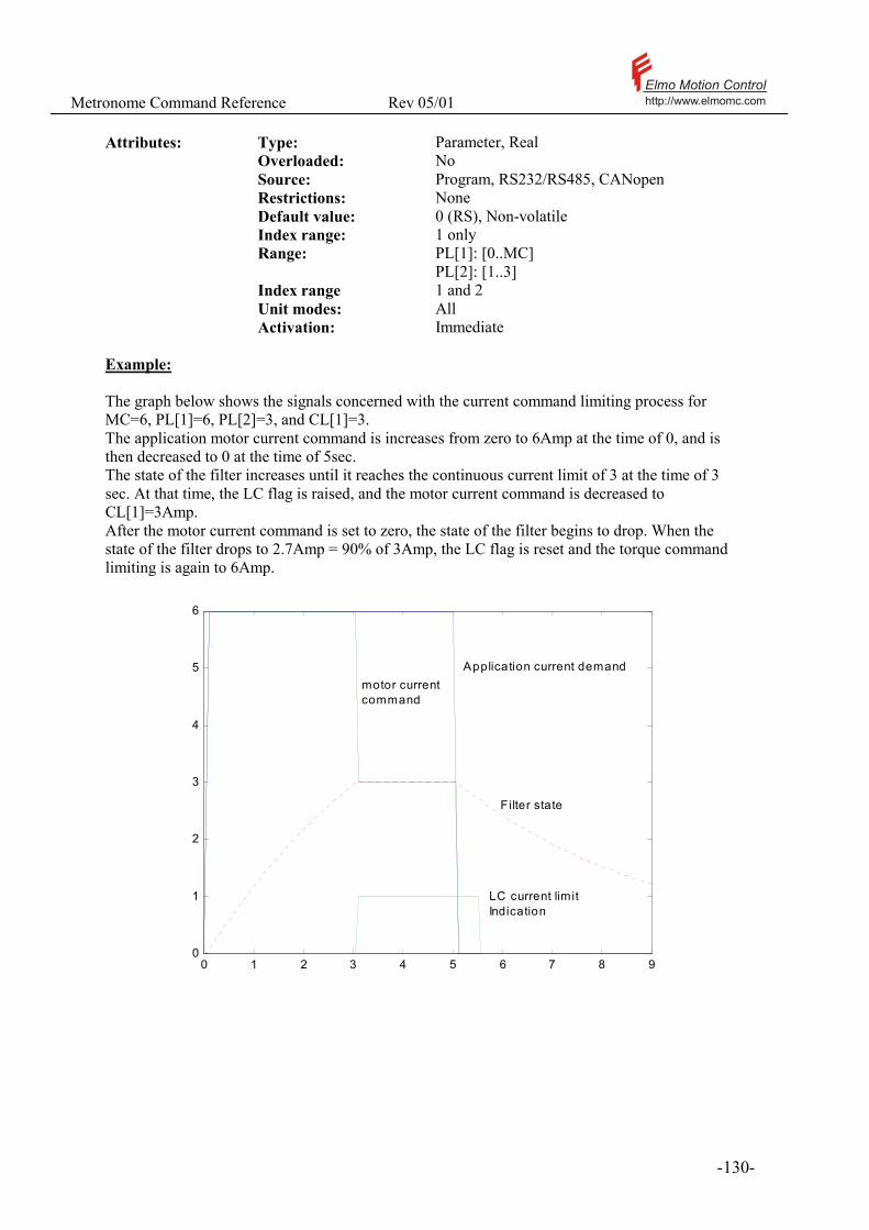
Metronome Command Reference Rev 05/01 Elmo Motion Controlhttp://www.elmomc.com
- 130 -
Attributes: Type: Parameter, Real Overloaded: No Source: Program, RS232/RS485, CANopen Restrictions: None Default value: 0 (RS), Non-volatile Index range: 1 only Range: PL[1]: [0..MC]
PL[2]: [1..3] Index range 1 and 2 Unit modes: All Activation: Immediate Example: The graph below shows the signals concerned with the current command limiting process for MC=6, PL[1]=6, PL[2]=3, and CL[1]=3. The application motor current command is increases from zero to 6Amp at the time of 0, and is then decreased to 0 at the time of 5sec. The state of the filter increases until it reaches the continuous current limit of 3 at the time of 3 sec. At that time, the LC flag is raised, and the motor current command is decreased to CL[1]=3Amp. After the motor current command is set to zero, the state of the filter begins to drop. When the state of the filter drops to 2.7Amp = 90% of 3Amp, the LC flag is reset and the torque command limiting is again to 6Amp.
0 1 2 3 4 5 6 7 8 90
1
2
3
4
5
6
Application current demand motor currentcommand
Filter state
LC current limitIndication
Metronome Command Reference Rev 05/01 Elmo Motion Controlhttp://www.elmomc.com
- 131 -
!The default (RS) value of PL[1] is 0. This value prevents any motor activation before the user sets PL[1] to its desired value.
!The peak duration PL[2] specifies the time it takes to switch from the peak limit to the continuous limit when the current PL[1] and PL[1] = MC. The actual time period for which the peak current may be applied can, however, vary significantly from PL[2].
• If PL[1] < MC, then longer time may be allowed for the peak current. This is done so since the peak limiting is made to protect the amplifier itself on the first place.
• If prior to the high current demand the current demand was very close to CL[1], then the switch will occur almost immediately.
• If the current demand is just a little bit more then CL[1], and a lot less then PL[1], it may take a very long time before the switch. The exact time it takes to switch may be calculated from the formulas above.
!If CL[1] ≥ PL[1], PL[1] will be the torque limit in effect all the time, and PL[2] will be ignored. See also: CL[N], LC, MC, TC

Metronome Command Reference Rev 05/01 Elmo Motion Controlhttp://www.elmomc.com
- 132 -
3.75 PM – Profiler Mode
Purpose:
PM defines if the speed command shall be applied as is, or be acceleration limited.
Value Description 0 The speed command is applied as is. If the speed command jumps, the motor speed
will be the step response of the speed controller. This mode is recommended if the servo drive implements an inner speed loop that is controlled by an outer feedback loop, since in introduces minimal tracking delay.
1 The speed command is limited in acceleration by the AC and the DC parameters, and smoothed as specified by the SF parameter. This mode is recommended if the speed command varies discontinuously, as in the RM=0 mode.
Attributes: Type: Parameter, Integer Source: Program, RS232/RS485, CANopen Restrictions: UM=2 Default value: 0 (RS), Non volatile Range: 0 or 1 Unit modes: 2 Activation: Immediate
See also: AC, DC, SF, RM
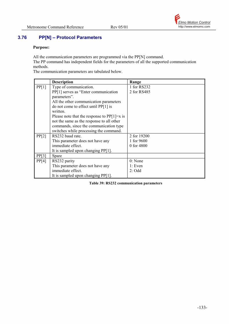
Metronome Command Reference Rev 05/01 Elmo Motion Controlhttp://www.elmomc.com
- 133 -
3.76 PP[N] – Protocol Parameters
Purpose: All the communication parameters are programmed via the PP[N] command. The PP command has independent fields for the parameters of all the supported communication methods. The communication parameters are tabulated below.
Description Range PP[1] Type of communication.
PP[1] serves as “Enter communication parameters”. All the other communication parameters do not come to effect until PP[1] is written. Please note that the response to PP[1]=x is not the same as the response to all other commands, since the communication type switches while processing the command.
1 for RS232 2 for RS485
PP[2] RS232 baud rate. This parameter does not have any immediate effect. It is sampled upon changing PP[1].
2 for 19200 1 for 9600 0 for 4800
PP[3] Spare PP[4] RS232 parity
This parameter does not have any immediate effect. It is sampled upon changing PP[1].
0: None 1: Even 2: Odd
Table 39: RS232 communication parameters
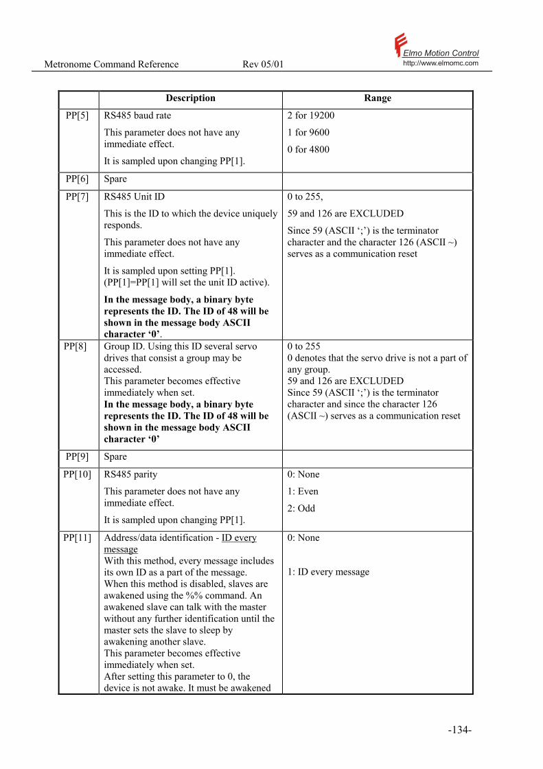
Metronome Command Reference Rev 05/01 Elmo Motion Controlhttp://www.elmomc.com
- 134 -
Description Range
PP[5] RS485 baud rate
This parameter does not have any immediate effect.
It is sampled upon changing PP[1].
2 for 19200
1 for 9600
0 for 4800
PP[6] Spare
PP[7] RS485 Unit ID
This is the ID to which the device uniquely responds.
This parameter does not have any immediate effect.
It is sampled upon setting PP[1]. (PP[1]=PP[1] will set the unit ID active).
In the message body, a binary byte represents the ID. The ID of 48 will be shown in the message body ASCII character ‘0’.
0 to 255,
59 and 126 are EXCLUDED
Since 59 (ASCII ‘;’) is the terminator character and the character 126 (ASCII ~) serves as a communication reset
PP[8] Group ID. Using this ID several servo drives that consist a group may be accessed. This parameter becomes effective immediately when set. In the message body, a binary byte represents the ID. The ID of 48 will be shown in the message body ASCII character ‘0’
0 to 255 0 denotes that the servo drive is not a part of any group. 59 and 126 are EXCLUDED Since 59 (ASCII ‘;’) is the terminator character and since the character 126 (ASCII ~) serves as a communication reset
PP[9] Spare
PP[10] RS485 parity
This parameter does not have any immediate effect.
It is sampled upon changing PP[1].
0: None
1: Even
2: Odd
PP[11] Address/data identification - ID every message With this method, every message includes its own ID as a part of the message. When this method is disabled, slaves are awakened using the %% command. An awakened slave can talk with the master without any further identification until the master sets the slave to sleep by awakening another slave. This parameter becomes effective immediately when set. After setting this parameter to 0, the device is not awake. It must be awakened
0: None
1: ID every message
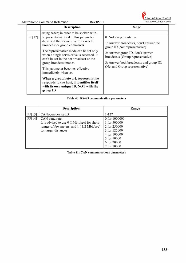
Metronome Command Reference Rev 05/01 Elmo Motion Controlhttp://www.elmomc.com
- 135 -
Description Range
using %%n; in order to be spoken with. PP[12] Representative mode. This parameter
defines if the servo drive responds to broadcast or group commands.
The representative mode can be set only when a single servo drive is accessed. It can’t be set in the net broadcast or the group broadcast modes.
This parameter becomes effective immediately when set.
When a group/network representative responds to the host, it identifies itself with its own unique ID, NOT with the group ID
0: Not a representative
1: Answer broadcasts, don’t answer the group ID (Net representative)
2: Answer group ID, don’t answer broadcasts (Group representative)
3: Answer both broadcasts and group ID. (Net and Group representative)
Table 40: RS485 communication parameters
Description Range
PP[13] CANopen device ID 1-127 PP[14] CAN baud rate.
It is advised to use 0 (1Mbit/sec) for short ranges of few meters, and 1 ( 1/2 Mbit/sec) for larger distances
0 for 1000000 1 for 500000 2 for 250000 3 for 125000 4 for 100000 5 for 50000 6 for 20000 7 for 10000
Table 41: CAN communications parameters

Metronome Command Reference Rev 05/01 Elmo Motion Controlhttp://www.elmomc.com
- 136 -
For the RS232 and the RS485 the number of stop bits is fixed to 1. Attributes: Type: Parameter, Real Overloaded: No Source: Program, RS232/RS485, CANopen Restrictions: MO=0 Default value: PP[1]=1,PP[2]=2,PP[3]=1,PP[5]=2,
PP[7]=1, PP[9]=1,PP[13]=1,PP[14]=1, All the rest default to zero (RS), Non-volatile
Index range: 1 only Range: As shown in the above table Index range 1 and 14 Unit modes: All Activation: RS232 and RS485 parameters are activated by
setting PP[1]. The exception are PP[8],PP[11], and PP[12] which are activated immediately. CANopen parameters are activated upon restarting the network through the NMT service – please refer the CANopen reference manual.
! It is most recommended to consult the software specification manual for the usage of each of the communication methods.

Metronome Command Reference Rev 05/01 Elmo Motion Controlhttp://www.elmomc.com
- 137 -
3.77 PR – Relative Position
Purpose: PR adds a to the target position in the next PTP (point-to-point) motion. If the Metronome has been set to PTP motion by a previous PA command, the next BG will do the following actions: PA+PR�Target of the next PTP motion PA=PA+PR. For detailed description of PTP motions, please refer the documentation of the PA command. Attributes: Type: Parameter, Integer Overloaded: No Source: RS232/RS485, CANopen, Program Restrictions: UM=4 or UM=5 and MO=1 Default: 0, Volatile. Cleared automatically at MO=1. Range: [-XM/2,XM/2-1] Unit modes: Position (UM=4 and UM=5) Activation: BG
! The PR command is a parameter of PTP motion, not a command. Setting PR does not specify that the next motion shall be of the PTP type. Example: PA=1000 ; PR=500 ; PA 1000; BG ; PA 1500; PR 500;
In the above dialogue, the absolute position target is set to 1000 and the relative position target is set to 500. After the BG command initiates the motion, the absolute position command becomes 1000+500=1500 and PR remains as is. See also: PA
Metronome Command Reference Rev 05/01 Elmo Motion Controlhttp://www.elmomc.com
- 138 -
3.78 PS - Program Status
Purpose: Reports the present executing program line. If the program is compiled but not running, PS returns (–1). If the program is not compiled, PS returns (–2).
Attributes: Type: Status report, Integer Overloaded: No Source: Program, RS232/RS485, CANopen Restrictions: None Unit modes: All Examples: PS -1 Indicates that the program is not running See also: CC, CS

Metronome Command Reference Rev 05/01 Elmo Motion Controlhttp://www.elmomc.com
- 139 -
3.79 PT – Position Time Command (++)
Purpose: PT specifies that the next BG shall start a PT (Position-Time) tabulated motion and defines the starting index in the QP array. In a PT motion, a new position reference value is picked from the QP array once per MP[4] sampling times. The motion is interpolated7 between the points specified by the QP array. The MP[] parameters specify which indices of the QP array are used for the motion. After BG, the PT motion starts from the position QP[PT]. A PT motion terminates when, in the none cyclical mode (MP[3]=0), the index of MP[2] is reached, or if the PT buffer underflows (CANopen only). When a PT motion terminates, the motor is brought to a complete stop using the SD deceleration. When a PT motion is executing, PT reads the presently executing index of the QP array.
Attributes: Type: Command/Parameter, Integer Source: Program, RS232/RS485, CANopen Restrictions: UM=4 or UM=5, MO=1, PT motion not
executing Default value: None, Volatile Range: [1..1024] Unit modes: Position control (UM=4 or 5) Activation: Next BG
! A PT motion can be initiated only when the motor position is close enough to QP[PT]. Otherwise, the motor will jump, or the motion shall be aborted due to an excessive position error.
! Please refer the software manual for a complete description of PT motions See also: PV, MP, QP, QV, QT
7 Using cubic interpolation

Metronome Command Reference Rev 05/01 Elmo Motion Controlhttp://www.elmomc.com
- 140 -
3.80 PV – Position Velocity Time Command (++)
Purpose: PV specifies that the next BG shall start a PV (Position-Velocity-Time) tabulated motion and defines the starting index in the motion table8 array. In a PVT motion, a new position reference value is picked from the PVT table at the time specified by the elements of the QT array. The motion is interpolated9 between the rows of the PVT table. The MP[] parameters specify which indices of the motion table are used for the motion. After BG, the PVT motion starts from the position QP[PV]. A PVT motion terminates when, in the none cyclical mode (MP[3]=0), the index of MP[2] is reached, or if the PVT buffer underflows (CANopen only). When a PVT motion terminates, the motor is brought to a complete stop using the SD deceleration. When a PVT motion is executing, PVT reads the presently executing index of the PVT table.
Attributes: Type: Command/Parameter, Integer Source: Program, RS232/RS485, CANopen Restrictions: UM=4 or UM=5, MO=1, PVT motion not
executing Default value: None, Volatile Range: [1..64] Unit modes: Position control (UM=4 or 5) Activation: Next BG
! A PVT motion can be initiated only when the motor position is close enough to QP[PV]. Otherwise, the motor will jump, or the motion shall be aborted due to an excessive position error. It is advised that the speed specified for the first PVT point will be almost equal to the speed when the motion has been initiated.
! Please refer the software manual for a complete description of PVT motions See also: PT, MP, QP, QV, QT
8 The PVT table is the combination of the QP,QV, and QT arrays. The n’th row of the PVT table consists of QP[n], QV[n], and QT[n]. 9 Using cubic interpolation

Metronome Command Reference Rev 05/01 Elmo Motion Controlhttp://www.elmomc.com
- 141 -
3.81 PX- Main Positions
Purpose: Read the position of the main encoder. Upon power on, the main position is set to zero. The variable PX accumulates the main encoder pulses. PX counts cyclically – please refer the XM command. The PX may be also used to fix the absolute position by typing PX=n. In the position control modes (UM=4 and UM=5) PX can be assigned a value only when the motor is of. This is since changing PX under position control may cause the motor to jump. In order to modify the position count under position control, use the HM command. PX may be assigned a value any time in the speed and the torque control modes. PX can be set to a known value with synchronization to the external event of homing or index – please refer the HM command. The main encoder direction is defined by CA[16]
Attributes: Type: Parameter/Status report, Integer Overloaded: No Source: Program, RS232/RS485, CANopen Reset value: 0, Volatile Restrictions: In UM=4 and UM=5, Setting PX requires
MO=1. PX cannot be set out of the modulo-limits as defined by XM.
Unit modes: All Example: PX 1000; Reports that the present main encoder reading is 1000. Typing MO=0;PX=2000; PX 2000; Sets the present main encoder position to 2000 counts. See also: HM, XM, CA
Metronome Command Reference Rev 05/01 Elmo Motion Controlhttp://www.elmomc.com
- 142 -
3.82 PY - Auxiliary Position
Purpose: Read the position of the auxiliary encoder. Upon power on, the auxiliary position is set to zero. The variable PY accumulates the auxiliary encoder pulses. PY counts cyclically – please refer the YM command. The PY may be also used to fix the absolute position by typing PY=n. In the dual loop position control modes (UM=4) PY can be assigned a value only when the motor is of. This is since changing PY under auxiliary position control may cause the motor to jump. In order to modify the auxiliary position count under position control, use the HY command. PY may be assigned a value any time in the speed and the torque control modes, and also in the single feedback position control mode (UM=5). PY can be set to a known value with synchronization to the external event of homing or index – please refer the HY command. The main encoder direction is defined by YD.
Attributes: Type: Parameter/Status report, Integer Overloaded: No Source: Program, RS232/RS485, CANopen Reset value: 0, Volatile. Restrictions: In UM=4, Setting PY requires MO=1. PY cannot
be set out of the modulo limits as defined by YM. Example: PY 1000; Reports that the present auxiliary encoder reading is 1000. Typing MO=0;PY=2000; PY 2000; Sets the present auxiliary encoder reading to 2000 counts. See also: YM, YD, HY
Metronome Command Reference Rev 05/01 Elmo Motion Controlhttp://www.elmomc.com
- 143 -
3.83 QP[N], QT[N], QV[N] – Position, Time, Velocity
Purpose: Store data for the PT and the PVT motion modes. Please refer the documentation of the PT, PV, and MP commands, and please consult the software manual for a complete description of the PT and the PVT motion modes. With CANopen communications, the QP, QV, and QT arrays can be high-speed-accessed using specially designed communication objects.
Attributes: Type: Command/Parameter, Integer Source: Program, RS232/RS485, CANopen Restrictions: QP values in the range [-XM/2,XM/2-1] Default value: 0, Volatile Range: QP - [1..1024]
QV and QT - [1:64] Unit modes: Position control (UM=4 or 5) Activation: Immediate.
! When a PT or a PVT motion is on, the user must be aware of the present value of the PT or PV in order to correctly feed the table.
See also: PT, PV, MP
Metronome Command Reference Rev 05/01 Elmo Motion Controlhttp://www.elmomc.com
- 144 -
3.84 RA[N] - Real Array
Purpose: Provides an array of 100 real numbers for general-purpose use.
Attributes: Type: Parameter, Real Overloaded: No Source: Program, RS232/RS485, CANopen Restrictions: None Default value: 0, Volatile Range: Unlimited Index range: [0:99] Unit modes: All Activation: Immediate Typical applications: General, look-up tables of real numbers, parameters for machine task definition. Examples: MO=0; IA[1]=100; RA[IA[1]]=IA[2]*SP/IA[4]; In the above example, the RA array is dynamically indexed by an element of the IA array. See also: IA

Metronome Command Reference Rev 05/01 Elmo Motion Controlhttp://www.elmomc.com
- 145 -
3.85 RC – Define recorded variables
RC defines which signals are to be recorded. The Metronome can record various signals for the purpose of performance verification and debugging. The first step of the recording process is the definition of the recorded variable by assigning a value to RC. RC is a bit field. Each “on” bit in the binary representation of RC defines a signal to be recorded. The table below correlates the bits in the binary representation of RC with the recorded signals.
RC Bit Number Vector To Record Variable name and Comment
0 Main Velocity VX 1 Position PX 2 Position command DV[3] 3 Digital Inputs This is the raw digital input
double word, NOT the IP variable. Please refer Table 46
4 Position error PE 5 Torque command DV[1] or TC 6 DC power supply voltage AN[5], Saxophone only 7 Auxiliary position PY, Models with auxiliary
encoder inputs only 8 Auxiliary speed VY, Models with auxiliary
encoder inputs only 9 Active motor current IQ for Saxophone
IM for Clarinet 10 Reactive motor current ID, Saxophone only 11 Analog input 1 AN[1]+AS[1].
This reading is taken without subtracting the offset – subtract AS[1] to get unbiased results.
12 Analog input 2 AN[2]+AS[2]. This reading is taken without subtracting the offset – subtract AS[2] to get unbiased results.
13 Current Phase A AN[3] Saxophone only 14 Current Phase B AN[4] Saxophone only 15 Velocity Command DV[2] 16-27 Reserved 28-31 Special variables Please refer the RP command
Table 42: RC Bits Assignment

Metronome Command Reference Rev 05/01 Elmo Motion Controlhttp://www.elmomc.com
- 146 -
A valid RC defines at least one recorded variable, and 4 recorded variables at most.
Attributes: Type: Parameter, Integer Source: Program, RS232/RS485, CANopen Restrictions: Recorder inactive (RR=0, or RR=-1) Default value: 1 (RS), Non-volatile Range: See command definition above. Unit modes: All Activation: Next initiation of the recorder (RR).
! If the Metronome stores an already recorded data vector, setting RC will invalidate this data. Invalidated data cannot be retrieved.
! The total number of data points that may be recorded is fixed to 4096. Therefore, the number of points per signal depends in the number of signals recorded simultaneously – the more signals are recorded, the less points are available for each signal. Examples: The RC value of 1 defines that only the main velocity is recorded. The RC value of 3 defines that the main position and the main velocity shall be defined simultaneously. RC=2000H defines that the A phase current shall be recorded in Saxophone. For Clarinet the setting RC=2000H is illegal. See also: RG, RL, RP, RR, BH
Metronome Command Reference Rev 05/01 Elmo Motion Controlhttp://www.elmomc.com
- 147 -
3.86 RG – Recorder gap
RG defines once per how many sampling times the recorder is activated. The recorder has a limited storage capacity. If the recorder operates at the sampling time of the Metronome, the recorded will operate for very short time. For longer recording times, the time interval between consecutive data recordings must be increased. The RG parameter trades recording resolution against the length of the recording time. With RG=1, the sampling time of the recorder will be WS[29]. WS[29]=TS for Clarinet, and for the torque and stepper unit modes of the Saxophone. WS[29]=4*TS for the speed and the position unit modes of the Saxophone.
Attributes: Type: Parameter, Integer Source: Program, RS232/RS485, CANopen Restrictions: Recorder inactive (RR=0, or RR=-1) Default value: 1 (RS), Non-volatile Range: [1..4096] Unit modes: All Activation: Next initiation of the recorder (RR).
! If the Metronome stores an already recorded data vector, setting RG will invalidate this data. Invalidated data cannot be retrieved. Example: Consider a Saxophone with TS=90, UM=2, and RL=100. For this sampling time and unit mode, we have WS[29]=360, so that the shortest available sampling time for the recorder is, with RG=1, 360µsec. The recorder time is 100*360µsec = 36msec. With RG=2, a sample of the recorded signal is taken once per 720µsec, and the recorder time is 72msec. See also: RC, RL, RP, RR, BH, TS, WS[29], UM
Metronome Command Reference Rev 05/01 Elmo Motion Controlhttp://www.elmomc.com
- 148 -
3.87 RI – Reset input
RI enables the Metronome to continue driving the motor after the motor has been stopped by the abort switch or by a limit switch. RI command must be used to confirm the stopping before any further motion is permitted. Before activating RI: Must be in analog reference mode. (RM=1). Switch must be activated according to IL for stop under servo control. Motion status must be done. (MS <= 1). After RI command: The software command is automatically set to (PX-external command) The software command is made stationary. The next motion mode is undefined, so that a motion mode command as PA or JV must be entered before a BG can initiate a motion. If there is a pending BG (by the BI command) it is cleared. Attributes: Type: Command, No value Overloaded: No Source: Program, RS232/RS485, CANopen Restrictions: MO=1, RM=1, MS<= 1 Unit modes: UM=4, UM=5 Activation: Immediate See also: BG, IL, UM

Metronome Command Reference Rev 05/01 Elmo Motion Controlhttp://www.elmomc.com
- 149 -
3.88 RL – Recorder length
RL specifies the length of the recorded data. The recorder can memorize 4096 data items. The maximum record length is as follows:
Number of simultaneously recorded signals
Maximum record length
1 4096 2 2048 3 1365 4 1024
RL may specify that the signal records shall be shorter then the maximum. If RL is set larger then the maximum record length (for example RC defines three recorded signals, but RL=2048), the recorder will still work. The length of the records, however, shall be shorter then RL.
Attributes: Type: Parameter, Integer Source: Program, RS232/RS485, CANopen Restrictions: Recorder inactive (RR=0, or RR=-1) Default value: 1024 (RS), Non-volatile Range: [1..4096] Unit modes: All Activation: Next initiation of the recorder (RR).
! If the Metronome stores an already recorded data vector, setting RL will invalidate this data. Invalidated data cannot be retrieved. Example: Please see the example for RG. See also: RC RG RP RR BH
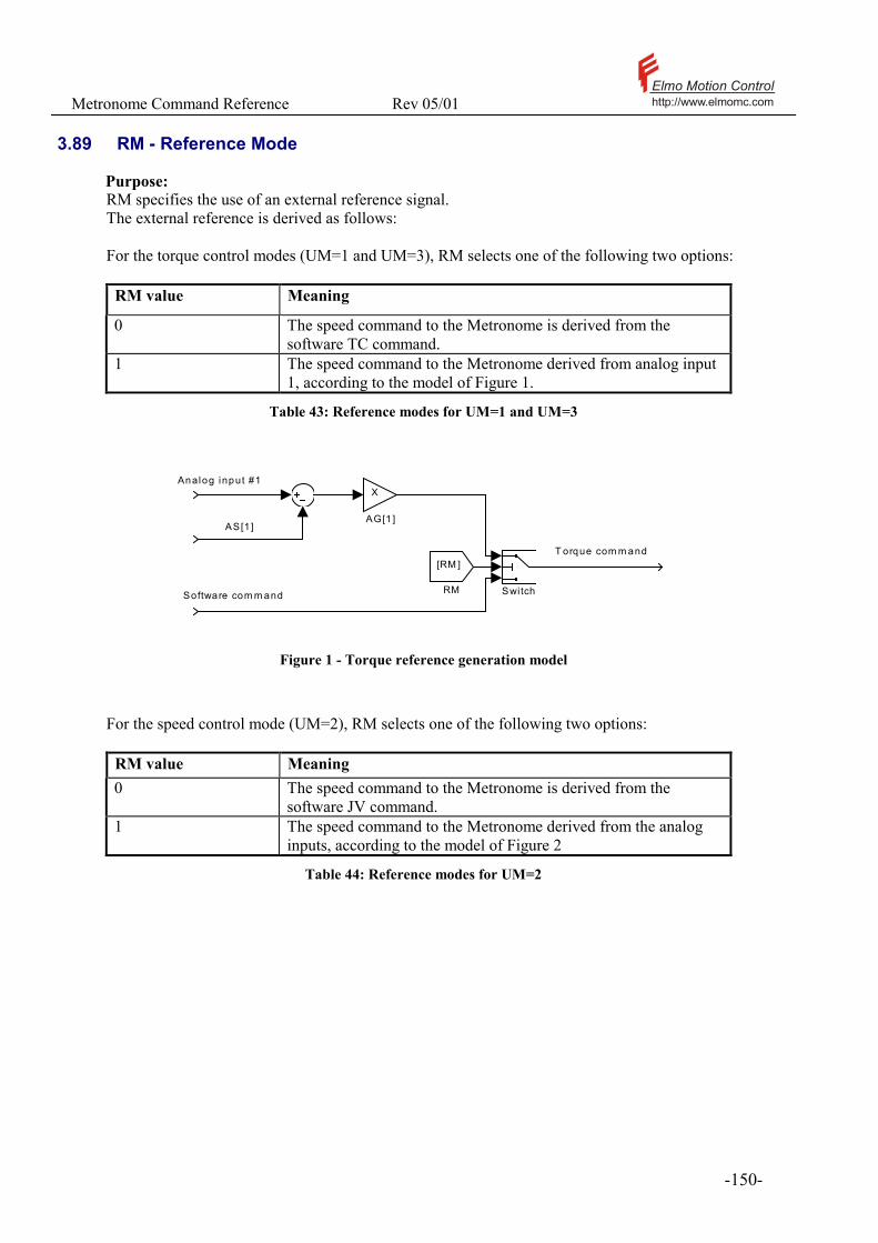
Metronome Command Reference Rev 05/01 Elmo Motion Controlhttp://www.elmomc.com
- 150 -
3.89 RM - Reference Mode
Purpose: RM specifies the use of an external reference signal. The external reference is derived as follows: For the torque control modes (UM=1 and UM=3), RM selects one of the following two options:
RM value Meaning
0 The speed command to the Metronome is derived from the software TC command.
1 The speed command to the Metronome derived from analog input 1, according to the model of Figure 1.
Table 43: Reference modes for UM=1 and UM=3
Analog input #1
AS[1]
Software com m and
T orque com m and
Switch
[RM ]
RM
X
AG[1 ]
Figure 1 - Torque reference generation model
For the speed control mode (UM=2), RM selects one of the following two options:
RM value Meaning 0 The speed command to the Metronome is derived from the
software JV command. 1 The speed command to the Metronome derived from the analog
inputs, according to the model of Figure 2
Table 44: Reference modes for UM=2

Metronome Command Reference Rev 05/01 Elmo Motion Controlhttp://www.elmomc.com
- 151 -
A n a l o g i n p u t # 1
A n a l o g i n p u t # 2
A S [1 ]
A S [2 ]
S o f t w a re c o m m a n d
S p e e dC o m m a n d
S w i t c h 1
S w i t c h
[ R M ]
R M
I n O u t
P ro f i l e r
[P M ]
P M
X
A G [ 2 ]
X
A G [ 1 ]
Figure 2 - Speed reference generation model
For the position control mode (UM=4 and UM=5), RM selects one of the following two options:
RM value Meaning 0 The position command to the Metronome is calculated only in software.
Please refer the PA, PR, JV, PT, and PV commands. 1 The position command to the Metronome is the sum of the software
position command and the external command. For the software position command, please refer PA, PR, JV, PT, and PV. The external position command is generated by the model of Figure 3.
Table 45: Reference modes for UM=4 and UM=5
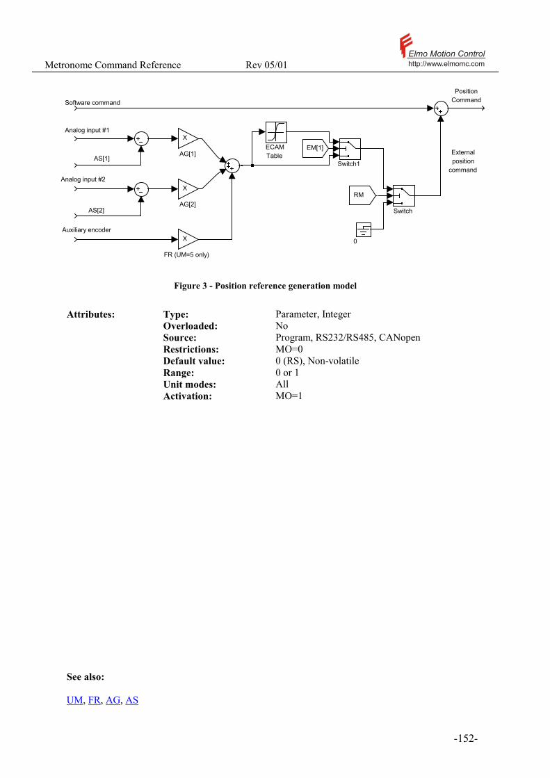
Metronome Command Reference Rev 05/01 Elmo Motion Controlhttp://www.elmomc.com
- 152 -
Analog input #1
Analog input #2
AS[1]
AS[2]
Auxiliary encoder
Software command Position
Command
Externalposition
commandSwitch1
Switch
0X
FR (UM=5 only)
EM[1]ECAMTable
X
AG[2]
X
AG[1]
RM
Figure 3 - Position reference generation model
Attributes: Type: Parameter, Integer Overloaded: No Source: Program, RS232/RS485, CANopen Restrictions: MO=0 Default value: 0 (RS), Non-volatile Range: 0 or 1 Unit modes: All Activation: MO=1 See also: UM, FR, AG, AS

Metronome Command Reference Rev 05/01 Elmo Motion Controlhttp://www.elmomc.com
- 153 -
3.90 RP[N] – Recorder parameters
The RP[N] parameters enables a complete specification of: • How the recorder is triggered • How the recorded data is transferred to the host.
Trigger definitions: The recorder is started by a trigger event. The trigger event may be one of the following: • Immediate: The recorder starts immediately after the recording request has been issued. • Triggered by an analog signal: The recorder starts upon the following event:
o A motion begin - A BG command, or the activation of a BI command. o Positive slope – The signal crosses a prescribed level with positive slope o Negative slope – The signal crosses a prescribed level with negative
slope o Window – The signals exits a window of two prescribed signal levels.
The picture below depicts the positive slope, negative slope, and window trigger types.
1 2 3 4 5 6 7-1
-0.8
-0.6
-0.4
-0.2
0
0.2
0.4
0.6
0.8
1
Trigger signal (not necessarily recorded)
Level 1
The trigger willoccur here if set for negative slope
The trigger willoccur here if set for positive slope
Level 2
The trigger willoccur here if set for window
Figure 4 - Slope and window trigger types

Metronome Command Reference Rev 05/01 Elmo Motion Controlhttp://www.elmomc.com
- 154 -
Triggered by a digital signal: The recorder is triggered by a combination of digital inputs from the raw digital input as given in the table below. Bits 8-11 of the raw digital input reflect the true switch position – they are not affected by the IL setting.
Bit 0-7 Unused Bit 8 FLS (Forward Limit switch) Bit 9 RLS (Reverse limit switch) Bit 10 Abort switch Bit 11 Enable switch Bit 12 Servo O.k. indication
Bit 13 1st Bit of servo status detail Bit 14 2nd Bit of servo status detail Bit 15 3rd Bit of servo status detail Bit 16 Uncommitted digital input 1 Bit 17 Uncommitted digital input 2 Bit 18 Uncommitted digital input 3 Bit 19 Uncommitted digital input 4 Bits 20-25 Unused Bit 26 Digital Hall input 1 Bit 27 Digital Hall input 2 Bit 28 Digital Hall input 3
Table 46: Raw digital inputs for the recorder
The next example demonstrates the trigger on digital input. Suppose that the trigger mask RP[7] is set to 30000H and the polarity RP[6] is set to 10000H. Therefore, only the uncommitted digital inputs 1 and 2 are watched. The trigger event occurs when the uncommitted digital input 1 is high and the uncommitted digital input 2 is low. Trigger delay The trigger defines when the recorder is to start. The recorder can be told to start before the trigger event, so that the trigger event can be caught in “the middle of the picture”. This is possible since the recorder starts to record at the instance it is launched by the RR command, so that when the trigger event occurs, the pre-trigger information is already recorded. The following picture example this. The trigger signal is the speed command and the recorded signal is similar. The trigger is set on BG. After launching the recorder with RR=3, the command sequence JV=5000;BG is entered. The results are shown in the picture below.
! Note that if a pre-trigger delay of 20% the recorder needs 2 seconds to acquire the pre-trigger data. Therefore, a BG that is set less then 2 seconds after the RR=3 will be missed.
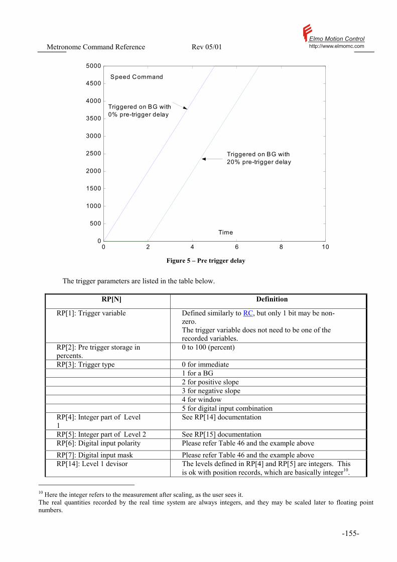
Metronome Command Reference Rev 05/01 Elmo Motion Controlhttp://www.elmomc.com
- 155 -
0 2 4 6 8 100
500
1000
1500
2000
2500
3000
3500
4000
4500
5000
Speed Command
Time
Triggered on BG with 0% pre-trigger delay
Triggered on BG with 20% pre-trigger delay
Figure 5 – Pre trigger delay
The trigger parameters are listed in the table below.
RP[N] Definition
RP[1]: Trigger variable Defined similarly to RC, but only 1 bit may be non-zero. The trigger variable does not need to be one of the recorded variables.
RP[2]: Pre trigger storage in percents.
0 to 100 (percent)
RP[3]: Trigger type 0 for immediate 1 for a BG 2 for positive slope 3 for negative slope 4 for window 5 for digital input combination RP[4]: Integer part of Level 1
See RP[14] documentation
RP[5]: Integer part of Level 2 See RP[15] documentation RP[6]: Digital input polarity Please refer Table 46 and the example above RP[7]: Digital input mask Please refer Table 46 and the example above RP[14]: Level 1 devisor The levels defined in RP[4] and RP[5] are integers. This
is ok with position records, which are basically integer10. 10 Here the integer refers to the measurement after scaling, as the user sees it. The real quantities recorded by the real time system are always integers, and they may be scaled later to floating point numbers.

Metronome Command Reference Rev 05/01 Elmo Motion Controlhttp://www.elmomc.com
- 156 -
RP[N] Definition
The current and the analog input measurements are small numbers, and they have meaningful fractions. Thus integer trigger levels are not sufficient for them. The new parameters RP[14] and RP[15] allow the statement of non-integer levels for recorder trigger. The levels are calculated as follows: Up slope level=RP[4]+(float)RP[14]/100 Down slope level=RP[5]+(float)RP[15]/100 The number 3.17512 will be sent as RP[4]=3 RP[14]=0.17512* 100=17
RP[15]: Level 1 devisor Same as RP[14] for level 2
Table 47: Trigger related RP parameters
The following parameters enable the BH command to fetch just the required part of the recorder results.
RP[8]: Index low Lower buffer index for recorded data transmission
RP[9]: Index high Higher buffer index for recorded data transmission, when RP[9]=RP[8]=0 all buffer is transmitted.
Table 48: Data upload related RP parameters

Metronome Command Reference Rev 05/01 Elmo Motion Controlhttp://www.elmomc.com
- 157 -
Attributes: Type: Parameter, Integer Source: Program, RS232/RS485, CANopen Restrictions: Recorder inactive (RR=0, or RR=-1) Default value: 1024 (RS), Non-volatile Range: [1..4096] Index range: [1..15] Unit modes: All Activation: Next initiation of the recorder (RR).
! If the Metronome stores an already recorded data vector, setting RP[N] with N other then 8 or 9 will invalidate this data. Invalidated data cannot be retrieved. ! the recorder parameters RP[10] to RP[13] enables the recording of every internal variable that has an address in the Metronome system. The variable of the memory address in RP[10] will be recorded if bit 28 of RC is set. Similarly, RP[11] to RP[13] contain the memory addresses of the variables specified by the RC bits 29-31. This feature is intended for emergency use only, and requires the user to know the memory location map of the Metronome variables.
See also: RC, RG, RL, RR, BH

Metronome Command Reference Rev 05/01 Elmo Motion Controlhttp://www.elmomc.com
- 158 -
3.91 RR – Activate recorder / Get recorder status
Purpose: RR launches the recorder, kills an on-going recording process, or retrieves the recorder status. The RR command has the following options:
RR Value Meaning
0 Kill the recorder (Do nothing if the recorder is not active) 1 Launch the recorder, triggered on the next BG. 2 Launch the recorder with immediate trigger. 3 Launch the recorder with the trigger defined by the RP parameters.
Table 49: RR command options
Note that the actions of RR=1 and RR=2 can be obtained with RR=3 and the appropriate RP[N] definitions. The commands RR=1 and RR=2 are simply meant to allow easy interface to the most common recorder actions. As a status inquiry, RR may return the following values:
RR Report Meaning -1 No valid data in the recorder. 0 The recorder action is complete, and it is loaded with valid data. 1,2,3 Waiting for the completion of RR=1, RR=2, or RR=3 respectively.
The report value of 1,2, and 3 does not tell if the recorder is already recording or is just waiting for a trigger. If this differentiation is required, use the SR command.
Table 50: RR reports
Attributes: Type: Parameter, Integer Source: Program, RS232/RS485, CANopen Restrictions: None Default value: -1, Volatile Range: [1..3] Unit modes: All Activation: Immediate
See also: BH, RP, RC, RG, RL, RR,

Metronome Command Reference Rev 05/01 Elmo Motion Controlhttp://www.elmomc.com
- 159 -
3.92 RS - Soft Reset
Purpose: The RS command initializes the Metronome parameters to their factory default, and resets all the volatile variables to their factory default.
Attributes: Type: Command, No value Overloaded: No Source: Program, RS232/RS485, CANopen Restrictions: MO=0, Program not running Unit modes: All excluding UM=1 Activation: Immediate
! RS does not change the communication settings, so after executing RS, it is still possible to communicate with the Metronome. The communication parameters are however reset. For example, if the baud rate is 9600, then setting PP[1]=1 immediately after RS will switch the baud rate to the default of 19200.
! The RS command is executed automatically if the LD (load parameters from flash) command fails. LD may fail after a firmware upgrade.
! The RS command disables the communication routines for a few milliseconds. If an RS is executed by an RS232/RS485 command, in the meanwhile a CAN message may be lost.
! The RS command modifies only the RAM contents – it does not affect the flash memory. Use the SV command to make the effect of RS permanent.
! After an RS command, the current limits are set to zero, so it impossible to start the motor immediately. After an RS, it is warmly advised to go through the steps of the Composer wizard before attempting to work with the motor. See also: LD, SV
Metronome Command Reference Rev 05/01 Elmo Motion Controlhttp://www.elmomc.com
- 160 -
3.93 RT – Return
Purpose: The RT command returns from a subroutine to the next line after the subroutine call. A subroutine call pushes the address just after the call to the call-stack and branches to the subroutine. The RT command pops the call-stack into the program counter. Attributes: Type: Command, No value Overloaded: No Source: Program Restrictions: None Unit modes: All Activation: Immediate Typical applications: None given. Examples: JS#@MY_PROC SP=1000; #@MY_PROC PA=10; RT The line JS#@MY_PROC pushes the address of the SP=1000; line into the call stack, then sets the program counter to point at the instruction PA=10. The RT commands pops the call-stack into the program counter so that after the RT command execution shall resume at the SP=1000 instruction.. See also: #@, JS, JZ
Metronome Command Reference Rev 05/01 Elmo Motion Controlhttp://www.elmomc.com
- 161 -
3.94 SA – Stepper Angle
Purpose: This commands applies only in the stepper mode (UM=3). In this mode the motor stator windings are excited so that the magnetic field they generate points to a given direction, regardless of the rotor direction. If the stator windings are excited with large enough current, the rotor will move until its magnets are aligned with the stator field. The SA command sets the electrical angle for the windings, in degrees.
Attributes: Type: Parameter, Integer Overloaded: No Source: Program, RS232/RS485, CANopen Restrictions: Stepper mode (UM=3) Default value: 0 (RS), Non-volatile Range: [0..359] Unit modes: Stepper (UM=3) Activation: BG
Examples: UM=3;MO=1;SA=0; BG; TC=1; The motor is started in the stepper mode, and the stepper angle is set to zero. After torque is applied by the TC command, the motor jumps so that the rotor is electrically aligned with the stator. SA=30 sets the stepper angle to 30 electrical degrees. This will cause a rotary motor with 2 pole pairs to move its shaft by 15 degrees. See also: TC, UM, MO

Metronome Command Reference Rev 05/01 Elmo Motion Controlhttp://www.elmomc.com
- 162 -
3.95 SC - Single Command
Purpose: Executes a single program command for program debugging. When the program runs under the single command mode, the conditions for activating automatic routines are never tested, and automatic routines will not be called.
Attributes: Type: Command, No value Overloaded: No Source: RS232/RS485, CANopen Restrictions: Program loaded to memory and compiled, not running. Unit modes: All Activation: Immediate Typical applications: Program debugging. Examples: SP=10000;AC=300000;MO=1 EN If the program is compiled and not running, and the program counter points at the first line of the example, SC will execute SP=10000, the next SC will execute AC=300000 and so forth. See also: XQ, XC,
Metronome Command Reference Rev 05/01 Elmo Motion Controlhttp://www.elmomc.com
- 163 -
3.96 SD – Stop Deceleration
Purpose: SD defines the deceleration (counts/sec/sec) that is used to stop position-controlled motions in the case of emergency. Position controlled motions cannot be stopped abruptly, because of the following reasons:
• The discontinuity in the reference speed may produce position errors in excess of ER[3]. Then the motor drive shall be cut to freewheeling, which may be a safety problem with high inertia or fast moving loads.
• If GS[9] is not correctly set, generating a large position error can destabilize the position controller.
The SD parameter must be defined as the largest deceleration in which the motor, aided by the friction, can apply to the load. The SD acceleration is applied in the following cases:
• An ST command, or an activation of an SI command. • Data underflow in a PT or in a PVT motion. • Detection of a limit switch or an abort switch.
Attributes: Type: Parameter, Integer Overloaded: No Source: Program, RS232/RS485, CANopen Restrictions: None Default value: 1000000 (RS), Non-volatile Range: [0..60000000] Unit modes: Position (UM=4 and UM=5) Activation: Immediate See also: DC, SI, ST
Metronome Command Reference Rev 05/01 Elmo Motion Controlhttp://www.elmomc.com
- 164 -
3.97 SF - Smooth Factor
Purpose: SF defines the motion smoothing-factor. Smoothing means that the motion speed profile “doesn’t have sharp corners”. The price is that the total time required for completing the motion increases. For SF>0, the acceleration to the required speed is not set immediately to its final value but it takes SF milliseconds to build. The total time required to complete the motion is increased in SF milliseconds. The maximum SF is 500 times the sampling time of the speed controller. If the speed controller has a sampling time of 200 microseconds, then the maximum SF value is 100 (milliseconds). In the position modes (UM=4,5) SF cannot be updated while a profiled motion is on.
Attributes: Type: Parameter, Integer Overloaded: No Source: Program, RS232/RS485, CANopen Restrictions: In UM=2: None
In UM=4,5: MO=0. Default value: 0 (RS), Non-volatile Range: [0..250*WS[29]] Unit modes: Speed (UM=2) Activation: BG Notes: 1. The Smoothing action applies for PTP and jogging motion only. SF does not affect tabulated motions like PT and PVT. SF also does not affect the analog part of the position reference in RM=1. Example: In this example, we apply the sequence MO=0;JV=4000;AC=100000;BG; with three different values of SF. The SF=0 graph displays sharp corners, since its acceleration is not continuous. The SF=10 graph takes 10 milliseconds more to stabilize the speed reference, but the speed reference profile is much smoother. For the SF=50 graph, the smoothing is so strong with respect to the total acceleration time that the AC acceleration is never achieved.

Metronome Command Reference Rev 05/01 Elmo Motion Controlhttp://www.elmomc.com
- 165 -
0 0.02 0.04 0.06 0.08 0.10
500
1000
1500
2000
2500
3000
3500
4000
SF=0 SF=10
SF=50
Time (sec)
Speed reference(count/sec)
Figure 6 - Smooth Factor model
See also: AC, DC, JV

Metronome Command Reference Rev 05/01 Elmo Motion Controlhttp://www.elmomc.com
- 166 -
3.98 SG - Save User Program
Purpose: Save user program from RAM to FLASH. The DL command downloads a program to the Metronome. The Metronome stores the program temporarily in a volatile memory. The program can be executed from the volatile memory, but it will be erased the next time power is shut down. The SG command may be used to store the program already downloaded to the Metronome in the non-volatile (Flash) memory. In the Metronome boot process, the Metronome checks the existence of a program in the non-volatile memory. If a program exists there, it is automatically loaded and compiled.
A program can be stored in the flash only if it has been successfully compiled. The exception is an empty program that may be stored in order to clear the Flash memory. Attributes: Type: Command, No value Overloaded: No Source: RS232/RS485,CANopen Restrictions: MO=0,Program loaded to memory and
compiled, not running. Unit modes: All Activation: Immediate See also: LG
Metronome Command Reference Rev 05/01 Elmo Motion Controlhttp://www.elmomc.com
- 167 -
3.99 SI – Stop On Input
Purpose: An ST (Stop) command suspended until any combination (0/1/Don’t care) of digital inputs 1,2,3, and 4 attains a desired pattern. The uncared digital inputs are defined by the SM variable. The desired polarity of the cared digital inputs is defined by the argument of the SM command. A new SI command overrides any pending SI. Use the MS command to observe if a pending SG has already been executed. Use SI=16 to cancel a pending SI command.
Attributes: Type: Command, Integer, Bit-field Overloaded: No Source: Program, RS232/RS485, CANopen Restrictions: MO=1.
In UM=2: RM=0 Range 0-16 Unit modes: All excluding UM=1 Activation: Immediate Typical applications: Stop motion with hardware timing Examples: SM=3; SI=1 The above code waits for Digital input 1 to be high, and for digital input 2 to be low for stopping motion. The digital inputs 3 and 4 are not cared. See also: ST, SM, IB, MS
Metronome Command Reference Rev 05/01 Elmo Motion Controlhttp://www.elmomc.com
- 168 -
3.100 SM - Stop Mask
Purpose: Defines which digital inputs are to be watched in a suspended stop (SI) command. The following table details the inputs watched for the possible SM values.
Value IB[1] IB[2] IB[3] IB[4] Comment 0 Ignore Ignore Ignore Ignore No inputs are watched.
Motion will start immediately upon a SI command, regardless of the argument of SI.
1 Watch Ignore Ignore Ignore 2 Ignore Watch Ignore Ignore 3 Watch Watch Ignore Ignore 4 Ignore Ignore Watch Ignore 5 Watch Ignore Watch Ignore 6 Ignore Watch Watch Ignore 7 Watch Watch Watch Ignore 8 Ignore Ignore Ignore Watch 9 Watch Ignore Ignore Watch 10 Ignore Watch Ignore Watch 11 Watch Watch Ignore Watch 12 Ignore Ignore Watch Watch 13 Watch Ignore Watch Watch 14 Ignore Watch Watch Watch 15 Watch Watch Watch Watch
Table 51: SM – Stop mask
From the time a SI command is issued and until it is executed, the digital inputs are continuously watched according to the value of SM. If SM is modified at this time, it will not affect the pending SI command – only the next one.
Attributes: Type: Parameter, Integer, Bit field Overloaded: No Source: Program, RS232/RS485, CANopen Restrictions: None Default value: 0 (RS), Non-volatile Range: [0..15] Unit modes: All Activation: SI
See also: SI, ST, IB, MS
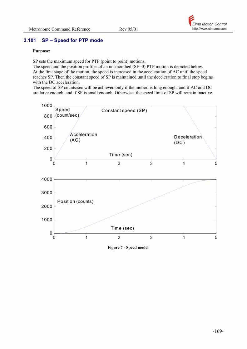
Metronome Command Reference Rev 05/01 Elmo Motion Controlhttp://www.elmomc.com
- 169 -
3.101 SP – Speed for PTP mode
Purpose: SP sets the maximum speed for PTP (point to point) motions. The speed and the position profiles of an unsmoothed (SF=0) PTP motion is depicted below. At the first stage of the motion, the speed is increased in the acceleration of AC until the speed reaches SP. Then the constant speed of SP is maintained until the deceleration to final stop begins with the DC acceleration. The speed of SP counts/sec will be achieved only if the motion is long enough, and if AC and DC are large enough, and if SF is small enough. Otherwise, the speed limit of SP will remain inactive.
0 1 2 3 4 50
200
400
600
800
1000
0 1 2 3 4 50
1000
2000
3000
4000
Acceleration(AC)
Deceleration(DC)
Constant speed (SP) Speed(count/sec)
Position (counts)
Time (sec)
Time (sec)
Figure 7 - Speed model

Metronome Command Reference Rev 05/01 Elmo Motion Controlhttp://www.elmomc.com
- 170 -
Attributes: Type: Parameter, Integer Overloaded: No Source: Program, RS232/RS485, CANopen Restrictions: SP≥VH[1] and VH[2] ≥SP Default value: 25000 (RS), Non-volatile. Range: [0, 8000000] (Sax)
[0, 1500000] (Clarinet) Unit modes: Position modes: UM=4,5 Activation: BG
! Specifying SP too high may cause HL[2] and LL[2] violations.
See also: HL, LL, AC, DC, SF, PA, RP
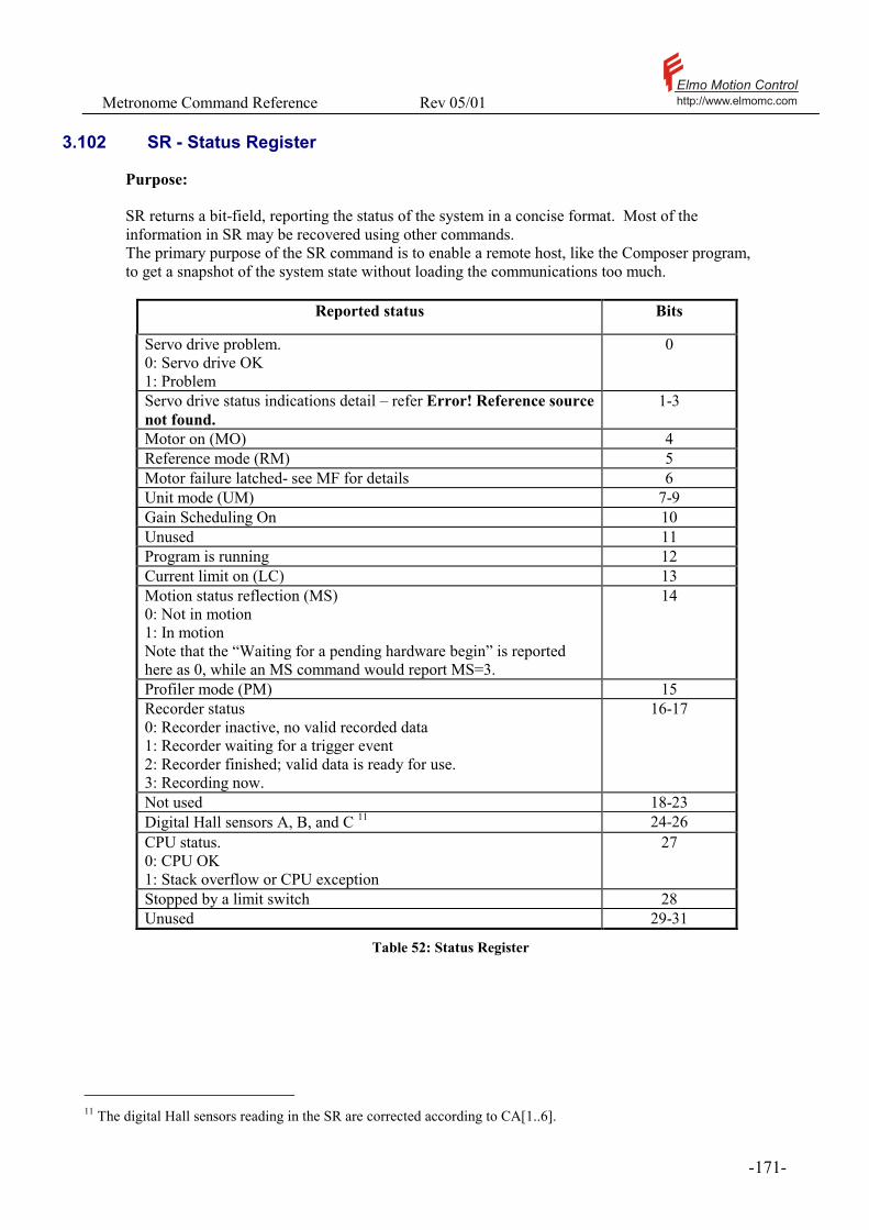
Metronome Command Reference Rev 05/01 Elmo Motion Controlhttp://www.elmomc.com
- 171 -
3.102 SR - Status Register
Purpose: SR returns a bit-field, reporting the status of the system in a concise format. Most of the information in SR may be recovered using other commands. The primary purpose of the SR command is to enable a remote host, like the Composer program, to get a snapshot of the system state without loading the communications too much.
Reported status Bits
Servo drive problem. 0: Servo drive OK 1: Problem
0
Servo drive status indications detail – refer Error! Reference source not found.
1-3
Motor on (MO) 4 Reference mode (RM) 5 Motor failure latched- see MF for details 6 Unit mode (UM) 7-9 Gain Scheduling On 10 Unused 11 Program is running 12 Current limit on (LC) 13 Motion status reflection (MS) 0: Not in motion 1: In motion Note that the “Waiting for a pending hardware begin” is reported here as 0, while an MS command would report MS=3.
14
Profiler mode (PM) 15 Recorder status 0: Recorder inactive, no valid recorded data 1: Recorder waiting for a trigger event 2: Recorder finished; valid data is ready for use. 3: Recording now.
16-17
Not used 18-23 Digital Hall sensors A, B, and C 11 24-26 CPU status. 0: CPU OK 1: Stack overflow or CPU exception
27
Stopped by a limit switch 28 Unused 29-31
Table 52: Status Register
11 The digital Hall sensors reading in the SR are corrected according to CA[1..6].

Metronome Command Reference Rev 05/01 Elmo Motion Controlhttp://www.elmomc.com
- 172 -
8H 4H 2H Meaning
0 0 0 O.k. 0 0 1 Under voltage – the power supply is shut down, or it has too
high impedance. 0 1 0 Over voltage. The voltage of the power supply is too large, or the
servo drive did not succeed in absorbing the kinetic energy while breaking a load. For a Clarinet servo drive, which does not have an internal shunt resistor, maybe a shunt resistor needs to be added.
0 1 1 SVP – Internal power supply is too low. This voltage is lower then the ‘under voltage’ range and may appear in conjunction with it. In these cases SVP will appear instead of ‘under voltage’.
1 0 1 Short circuit. The motor or its wiring may be defective.
1 1 0 Temperature. Amplifier overheating. The environment is too hot, or bad heat removal. Possible reasons: Blocked air inlet or faulty fan (Saxophone) Large thermal resistance between the amplifier and its mounting (Clarinet).
1 1 1 Commutation – Since the Metronome perform the commutation internally this message is not likely to appear. Value of 7 will usually be the conjunction of SVP and ‘External Disable’. External Disable is being set at motor off.
Table 53: Servo drive status indications
Attributes: Type: Status report, Integer, Bit-field Overloaded: No Scope: Program, RS232/RS485, CANopen Restrictions: None Unit modes: All See also: MF, RR, PM, UM, RM, IP, MS, MO, LC
Metronome Command Reference Rev 05/01 Elmo Motion Controlhttp://www.elmomc.com
- 173 -
3.103 ST - Stop Motion
Purpose: The ST command stops the present software motion. In the speed control mode (UM=2), ST decelerates the speed command to zero, using the DC deceleration. In the position control modes, (UM=4 or UM=5) ST decelerates the software position command (Please refer the RM command) with the SD deceleration. ST does not affect the external position reference. An ST command overrides and cancels a pending SI command.
Attributes: Type: Command, No value Overloaded: No Source: Program, RS232/RS485, CANopen Restrictions: MO=1, UM=2 and RM=1, or UM=4, or UM=5. Unit modes: UM=2, 4, or 5. Activation: Immediate
See also: BG, SI, RM
Metronome Command Reference Rev 05/01 Elmo Motion Controlhttp://www.elmomc.com
- 174 -
3.104 SV - Save Parameters To Flash
Purpose: The SV command saves the entire set of non-volatile variables from the RAM to the Flash memory. Before saving, the parameters in the RAM are tested to be in range and consistent. If the test fails, the SV command exits with error and the flash contents remain as is. The SV command does not save the user program. Please refer the SG command.
Attributes: Type: Command, No value Overloaded: No Source: Program, RS232/RS485, CANopen Restrictions: MO=0 Unit modes: All Activation: Immediate
! The SV command may take few hundreds of msec to execute, in which the communication drivers are disabled. If a SV command is executed by an RS232/RS485 command, in the meanwhile a CAN message may be lost, and vice versa.
See also: LD
Metronome Command Reference Rev 05/01 Elmo Motion Controlhttp://www.elmomc.com
- 175 -
3.105 TC - Torque Command
Purpose: TC sets the torque (motor current) command in Amperes, for the torque-control software-reference modes (UM=1 and UM=3, RM=0). TC commands are accepted in the range permitted by the present torque command limits – please refer the commands PL and CL. If TC is set greater then CL[1], then after few seconds the current-limit of the servo drive will drop to CL[1], and TC will report CL[1]. For discrete-commutation servo drives (like the Clarinet) TC defines the motor-current command. For continuous commutation servo drives (like the Saxophone) TC defines the IQ command (the ID command is always zero). Please note that IQ is defined in the RMS sense, so that with TC=1, the maximal phase current (taken over a full rotation of the motor) will be 1.414Amp.
Attributes: Type: Command/Parameter, Real Overloaded: No Source: RS232/RS485, CANopen, Program Restrictions: MO=1, UM=1 or UM=3 and RM = 0. Default: 0, Volatile. Cleared automatically at MO=1. Range: [-MC,MC] Unit modes: Torque or stepper (UM=1 and UM=3) Activation: Immediate Example: UM=1;PL[1]=10;CL[1]=5;MO=1;TC=10 The sequence above will start the motor with the maximum available torque. Typing TC will return 10. After few seconds, the current limit will drop to the continuous limit of 5Amp. Typing TC now will return 5. If the motor reaches its maximal speed and its generated voltage matches the power supply, the servo drive will no longer be able to drive 5Amp, and the actual motor current shall drop to, say, 1Amp. The current limit will reset to the peak 10Amp limit, but the torque command will remain 5Amp. See also: MO, UM, IM, IQ, ID, CL, PL
Metronome Command Reference Rev 05/01 Elmo Motion Controlhttp://www.elmomc.com
- 176 -
3.106 TG - Analog Gain For Tacho Feedback (Clarinet only)
Purpose: Set the gain tachometer feedback. The main speed measurement12 may come from one of the following sources:
• The speed is derived from the pulses of the position encoder • The resolver-to-digital converter derives the speed (resolver systems only) • The speed is measured directly by a tacho-generator.
The tacho feedback is preferred in the following conditions:
• A very smooth slow speed motion is desired. • There is a large friction • There is a large difference between the static and the dynamic friction.
When Tacho feedback is activated by setting CA[8] = 1. The speed feedback is given by: VX[count/sec]=TG[(count/sec)/volt]*(analog input2 – AS[2])[volt]. Using a negative TG may reverse the polarity of the tachometer signal. Attributes: Type: Parameter, Real Overloaded: Yes Source: Program, RS232/RS485, CANopen Restrictions: MO=0 Default value: 0 (RS), Non volatile Range: UM=2 : [-1000000,1000000] Unit modes: All Activation: Immediate
! The tachometer feedback uses analog input #2. If a tachometer feedback is used, analog input #2 cannot be used as a reference input, and the value of AG[2] is ignored.
! The tacho input is limited to +/-10v. Exceeding this value may damage the hardware. Older tachometers develop large voltages, and must be attenuated by a voltage divisor before coupling them to the amplifier.
! If the tacho is the only feedback device and there is no position measurement device (CA[21]=0), then TG losses its “volt to count/sec” meaning. In that case set TG=10000 or TG=-10000, according to the tacho direction.
12 The main speed measurement serves as the speed feedback either for a stand-alone speed controller (UM=2) or for the inner loop controller of a dual loop arrangement (UM=4).

Metronome Command Reference Rev 05/01 Elmo Motion Controlhttp://www.elmomc.com
- 177 -
Examples: In a dual loop application, the inner speed controller uses a tacho for feedback, and the outer position loop has an encoder feedback. Assume: Motor to encoder gear ratio 1 Encoder resolution 4000 counts/rev (1000 lines/rev) Tacho gain 3v/1000rpm One volt at the tachometer output is equivalent to 1000/3 encoder rotations per minute, which are (1000/3)*(4000/60) = 22222 counts/sec at the encoder. We shall set: CA[8]=1 TG=22222 FF=1. See also: CA, AS, FF, UM

Metronome Command Reference Rev 05/01 Elmo Motion Controlhttp://www.elmomc.com
- 178 -
3.107 TR – Target Radius
The TR command defines the criterion for deciding that a motion is done and the motor is stabilized in place with the required accuracy. The required accuracy is defined in the terms of target radius and target time. The target radius is the maximum positioning error allowed for static stabilization (this is not to be confused with the ER [] parameters that assert the dynamic stabilization error that is considered a fault). The target time is the minimum time the (absolute value of the) error must be within the target radius in order to decide that the motor is stabilized in place. The target time and the target radius concepts are demonstrated in the drawing below.
0.011 0.012 0.046 0.050 0.0740
200
400
600
800
100
120
140
Target
Time
In this drawing we see an overshooting settling of the position on a target at 1000 counts, with the target radius of 2. The target zone is the range of [98-102] counts. At the time intervals [0.011,0.012] and [0.046,0.050] the motor is inside the target radius, but still not stabilized. If the target time is taken less then 4 milliseconds, a false final stabilization may be concluded at the time of 0.050. TR[1] – Defines the target radius in counts. TR[2] – Defines the target time in milliseconds. When target is with in radius for the minimum given time, MS will be set to 0.

Metronome Command Reference Rev 05/01 Elmo Motion Controlhttp://www.elmomc.com
- 179 -
Attributes: Type: Parameter, Integer Source: Program, RS232/RS485, CANopen Restrictions: MO=1 Default value: TR[1]:100,TR[2]:20 (RS), Non-volatile Range: TR[1]:[0,32000],TR[2]:[0,1000] Unit modes: Position (UM=4 and UM=5) Activation: Immediate
Examples: Command Meaning.. Further more MO=0 Set motor off PX=0 Reset position Just for the sample UM=5 Position mode TR[1]=5 Radius is ±5 counts TR[2]=2 Stay steady for at least
2mSecs
MO=1 Set motor On PA=PX Switch to PTP BG Start motion PR=400 Position relative 400 counts BG Start motion AF,MS=0 Wait for steady state
according to TR[1]& TR[2] The target position range is [395 – 405]
PR=-400 Back 400 counts BG After being steady for 2 milliseconds in the range 400±5, motor will travel back 400 counts. See also: MS
Metronome Command Reference Rev 05/01 Elmo Motion Controlhttp://www.elmomc.com
- 180 -
3.108 TS – Sampling time
TS define the sampling time of the Metronome, in microseconds. For the Saxophone, TS is the sampling time of the torque controller. The sampling time for the speed and the position controllers of the SAX is ⋅4 TS. For the Clarinet, TS is the sampling time of the speed and position controller. The selection of TS is a compromise between high Metronome performance and the speed in which user programs run. A low TS enable the Metronome to achieve more control bandwidth, but at the same time increases the computational burden on the CPU, so that less computing power is left for executing the user program. The Metronome does not permit a too low value for TS, in order not to overflow the required CPU computing power. The minimum TS is mode dependent, since some modes require less CPU then other modes and can thus survive with smaller TS. The minimum TS can be found out as follows:
WI[3] The minimum sampling time for UM=1 (Refer the TS command) WI[4] The minimum sampling time for UM=2 (Refer the TS command) WI[5] The minimum sampling time for UM=3 (Refer the TS command) WI[6] The minimum sampling time for UM=4 (Refer the TS command) WI[7] The minimum sampling time for UM=5 (Refer the TS command)
For all the products and all the unit modes, WS[29] gives the actual sampling time of the speed or the position controller.
Attributes: Type: Parameter, Integer Overloaded: No Source: RS232/RS485, CANopen Restrictions: MO=0, Program not running Default value: WI[7] (RS), Non-volatile Range: At least the minimum sampling time for the mode,
and at most four times the minimum sampling time for the mode.
Unit modes: All Activation: Immediate
! The TS command may take few msec to perform, since it completely re-calculates the Metronome database. At this time, the communication routines are disabled. If an TS command is executed by an RS232/RS485 command, in the meanwhile a CAN message may be lost, and vice versa.
See also: WI, WS
Metronome Command Reference Rev 05/01 Elmo Motion Controlhttp://www.elmomc.com
- 181 -
3.109 UM – Unit mode
Purpose: UM defines the Metronome configuration. Value Description 1 Torque control mode.
In this mode, the motor-current command is set directly by the software command JV or by an analog reference signal. This mode is useful for: Torque or force control When the servo drive is used only as an inner device within an external feedback loop.
2 Speed control mode. In this mode, the motor speed command is set directly by the software command JV or by an analog reference signal.
3 Micro Stepper mode. In this mode, no commutation is made. The user controls the field angle directly by the SA command and the motor-current (holding torque) by the TC command or by an analog signal. This mode has been implemented mainly for the purpose of testing and calibration. Its main advantage there is that in this mode current may be safely applied to the motor before any feedback loop is closed. The Micro Stepper mode causes significant vibrations for discrete commutation servo drives like the Clarinet, and is not available for DC motors.
4 Dual loop position control. In this mode, the position controller stabilizes the position of the auxiliary feedback input. The position controller issues a motor speed command to an inner speed control loop. The inner speed control loop derives its speed feedback from the main feedback input. The position command composed from a software command and from an external command. Please refer the software manual for detailed description of how the position reference signal is generated.
5 Single loop position control. In this mode, the position controller stabilizes the position of the main feedback input. The position command composed from a software command and from an external command. Please refer the software manual for detailed description of how the position reference signal is generated.

Metronome Command Reference Rev 05/01 Elmo Motion Controlhttp://www.elmomc.com
- 182 -
The unit mode is reflected in the SR report. The different unit modes imply very different CPU loads for the Metronome. Therefore, the minimum sampling time that can be set depends in the unit mode. UM cannot be set to a mode for which the sampling time is too short. For example, if UM=1 and TS is set to its minimum value for UM=1, then UM=4 cannot be set before TS is sufficiently increased. Attributes: Type: Parameter, Integer Overloaded: No Source: Program, RS232/RS485, CANopen Restrictions: MO=0, TS set long enough for the unit mode, as
reported by the WI[3] to WI[7] reports. Default value: 3 (RS), Non-volatile Range: 1-5 Unit modes: All Activation: Immediate
See also: RM, SR, TS, WI
Metronome Command Reference Rev 05/01 Elmo Motion Controlhttp://www.elmomc.com
- 183 -
3.110 VE - Velocity Error
Purpose: VE reports the present position tracking error. In the speed mode (UM=2) and in the dual-feedback position mode (UM=4), VE reads VE = DV[2] – VX. If the absolute value of VE exceeds ER[2], motion is aborted and the motion fault code MF=80H=128 is set. If MO=0, or if the speed controller is not used (UM=1,3, or 5), VE returns 0.
Attributes: Type: Status report, Integer Overloaded: No Source: Program, RS232/RS485, CANopen Restrictions: None. Unit modes: All See also: ER, MF, UM

Metronome Command Reference Rev 05/01 Elmo Motion Controlhttp://www.elmomc.com
- 184 -
3.111 VH[H],VL[N] – High and low Reference Limit
Purpose: VL[N] and VH[N] define the minimum and the maximum limits for speed and position reference to the Metronome. Software commands beyond these values shall not be accepted, and analog commands beyond these values will be truncated to the corresponding VH[N] or VL[N] parameters.
. • The reference to the speed controller is limited to the range [VL[2]..VH[2]] • The reference to the position controller is limited to the range [VL[3]..VH[3]]
! If the motion is unlimited, set VH[3] > XM/2 and VL[3] < -XM/2. This way, VL[3] and VH[3] becomes ineffective, as the position reference is always in the range [-XM/2,XM/2-1].
Attributes: Type: Command/Parameter, Real Overloaded: No Source: RS232/RS485, CANopen, Program Restrictions: MO=0 Default: VH[2]=1000000,
VH[3]=10000000, VL[2]=-10000000, VL[3]=-100000000 (RS) Nonvolatile.
Range: Clarinet: VH[2],VL[2]= ±1500000 Saxophone: VH[2],VL[2]= ±8000000 VH[3],VL[3]= [-231 , 231 – 1]
Unit modes: VH[2],VL[2]: UM=2 and UM=5 VH[3],VL[3]: UM=4 and UM=5
Activation: Immediate
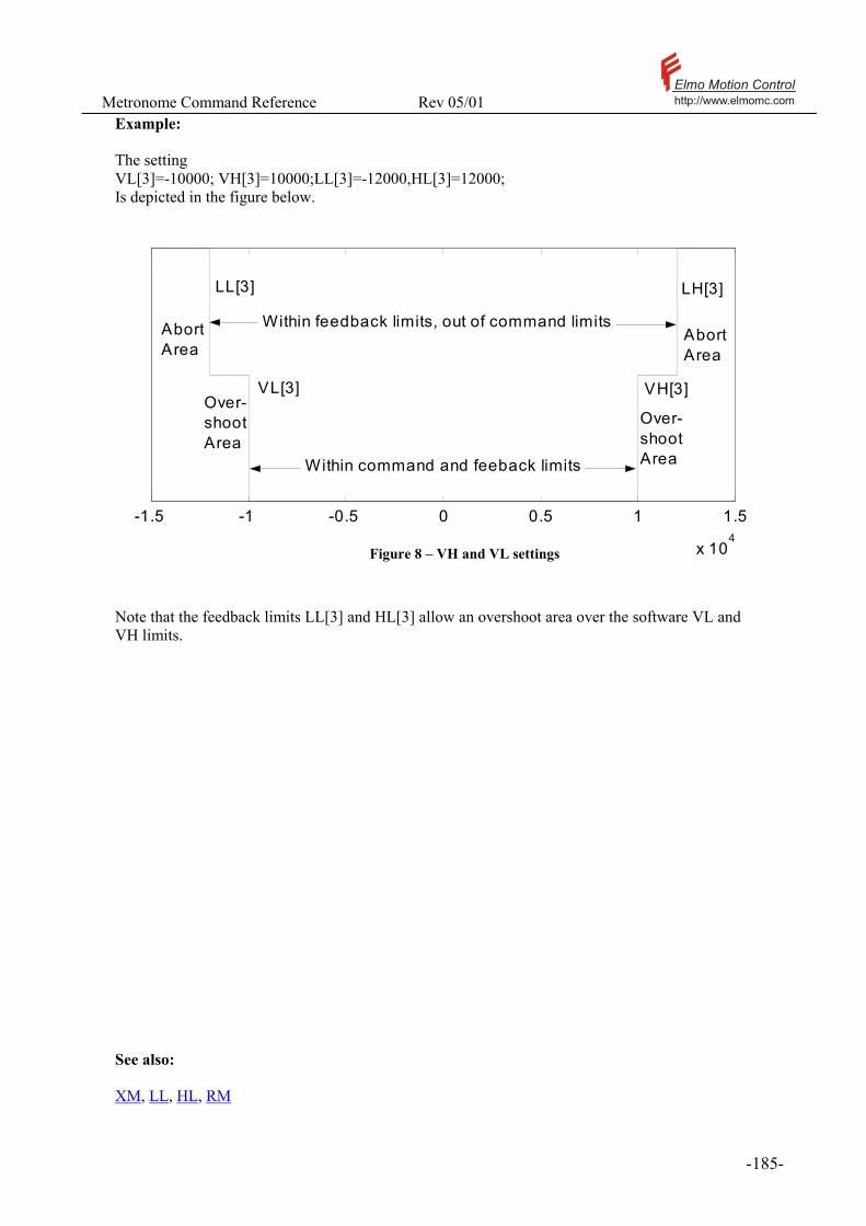
Metronome Command Reference Rev 05/01 Elmo Motion Controlhttp://www.elmomc.com
- 185 -
Example: The setting VL[3]=-10000; VH[3]=10000;LL[3]=-12000,HL[3]=12000; Is depicted in the figure below.
-1.5 -1 -0.5 0 0.5 1 1.5
x 104
Within command and feeback limits
VL[3] VH[3]
LL[3] LH[3]
Within feedback limits, out of command limits AbortArea
AbortArea
Over-shootArea
Over-shootArea
Figure 8 – VH and VL settings
Note that the feedback limits LL[3] and HL[3] allow an overshoot area over the software VL and VH limits. See also: XM, LL, HL, RM
Metronome Command Reference Rev 05/01 Elmo Motion Controlhttp://www.elmomc.com
- 186 -
3.112 VR - Firmware Version
Purpose: Reports the version of the firmware as a string. This string includes: - The product name - The software version - The software release date This command is intended for the use of RS232/485 communication only. CANopen users should read the software version using the object 0x100a of the object dictionary. Attributes: Type: Status report, String Overloaded: No Source: Program, RS232/RS485 Restrictions: None Unit modes: All
Examples: VR Clarinet FW002_CM001_C000_A002 6June2000 - The product name is Clarinet - The software version is FW002_CM001_C000_A002 - The software release date is 6June2000 See also: None

Metronome Command Reference Rev 05/01 Elmo Motion Controlhttp://www.elmomc.com
- 187 -
3.113 VX - Velocity Of Main Feedback
Purpose: The VX status inquiry returns the speed of the main feedback. The VX variable is calculated for the purpose of providing the stabilizing feedback to the Metronome. This is a high quality signal with very good resolution and minimal delay. The VX signal is calculated using the time difference measured between consecutive encoder pulses.
Attributes: Type: Status report, Integ Overloaded: No Source: Program, RS232/RS485, CANopen Restrictions: None Unit modes: All See also: PX
Metronome Command Reference Rev 05/01 Elmo Motion Controlhttp://www.elmomc.com
- 188 -
3.114 VY - Velocity Of Auxiliary Feedback
Purpose: The VY status inquiry returns the speed of the auxiliary feedback. The VY variable is calculated for the purpose of display only. It is not used for feedback control. The VY variable is calculated by passing the auxiliary encoder counts via a numerical derivative. The numerical derivative introduces a delay of about 10msec. The quality of the VY signal is not as good as the quality of the VX signal. It has higher level of noise and higher delay than VX.
Attributes: Type: Status report, Integer Overloaded: No Source: Program, RS232/RS485, CANopen Restrictions: None Unit modes: All See also: PY

Metronome Command Reference Rev 05/01 Elmo Motion Controlhttp://www.elmomc.com
- 189 -
3.115 WI[N] – Extended state, Integer
Purpose: The WI status vector reports some integer constants and variables of the system that are more usually used by the Composer program then directly by the users. The following table details the WI report.
Index Description WI[1] Returns
(Resolver reading) – (Main position counter), sampled at the last time when the absolute position of the resolver has been read. The absolute position of the resolver is read at system boot, and when setting the resolver offset or counting direction.
! WI[1] always reads the raw reading of the resolver counter. If the position reading direction is inverted with respect to the resolver, then WI[1] is not well defined.
WI[2] A direction compensated version of WI[1]. If the position counter reads at the same direction as the resolver, WI[2] = WI[1]. If the position counter reads opposite to the direction of the resolver, WI[2] = (CA[18] - (Resolver reading)) – (Main position counter)
WI[3] The minimum sampling time for UM=1 (Refer the TS command) WI[4] The minimum sampling time for UM=2 (Refer the TS command) WI[5] The minimum sampling time for UM=3 (Refer the TS command) WI[6] The minimum sampling time for UM=4 (Refer the TS command) WI[7] The minimum sampling time for UM=5 (Refer the TS command) Attributes: Type: Command/Status report, Integer Overloaded: No Source: Program, RS232/RS485, CANopen Restrictions: None. Unit modes: All See also: WS, TS

Metronome Command Reference Rev 05/01 Elmo Motion Controlhttp://www.elmomc.com
- 190 -
3.116 WS[N] – Extended state, Floating point
Purpose: The WS status vector reports some floating point constants and variables of the system that are more usually used by the Composer program then directly by the users. The following table details the WS report.
Index Description WS[1] Not used WS[2] Test mode.
0: Normal operation 1: Running speed step response test 2: Rotating the motor in the stepper mode, as is done when the composer initializes the commutation data. 3: Running speed step response test with gain scheduling 10: Running position loop response test 11,12,13,14: Running calculation related to the auto tuning process
WS[3] Clock frequency. The frequency of the CPU clock. WS[4] PWM frame. The PWM resolution (Saxophone) WS[5] A/D factor: The number of A/D bits per sensed motor current of 1Amp. WS[6] The database version. This data is required for the Composer to decide its
compatibility to a certain Metronome version. WS[7] Equal to MC WS[8] The state of the current limiting filter – please refer the PL command. WS[9] Not used WS[10] Present torque limit, in Amperes – please refer the PL command. WS[11] Hardware position sensor option:
1: Encoder 2: Resolver
WS[12] Shoot through delay in counter clocks (Saxophone). WS[13] Not used WS[14] Amplifier torque command, in internal units WS[15] Last oscillation amplitude in an auto phasing process. An auto phasing process is
executed when a motor is to start on the basis of encoder reading without digital Hall sensors – please refer the CA[20] parameter of the CA command
WS[16] If 1, then the last auto phasing process (see WS[15] above) terminated with failure due to bad frequency selection. At a “bad” frequency, the effect of viscous damping or of a mechanical resonance may be too noticeable.
WS[17] Figure of merit for current controller auto tuning (Saxophone) WS[18] Line voltage measurement (Saxophone) WS[19] Not used WS[20] The electrical angle of the stator field (1024 counts per electrical revolution) WS[21] Commutation counter (cyclical counter in encoder units, cycle = one motor revolution) WS[22] The ratio between internal torque command (in bits) and the resulting current in
Amperes. Index Description WS[23,35] Not used WS[24] Failure address. In the case of fatal CPU exception, report the code location of the
fault. Index Description

Metronome Command Reference Rev 05/01 Elmo Motion Controlhttp://www.elmomc.com
- 191 -
WS[26] Recorder counter. Reports the state of the recording process while recording is still on. WS[27] Reports the automatically tuned offset of the A phase curren (Saxophone) or the motor
current (Clarinet) WS[28] Reports the automatically tuned offset of the B phase curren (Saxophone) WS[29] The sampling time of the slowest Metronome in the configuration.
For example, Saxophone with UM=2 (speed control) and TS=90: The current controller runs in 90µsec, as stated by TS. The speed controller runs slower, once per 4*TS = 360µsec. WS[29] shall report 360.
WS[30] Product information code. Reports the product name, type of I/Os installed, expansion cards, presence of CAN UART, etc.
WS[31]-WS[62]
Reports intermediate results in the process of auto tuning.
Attributes: Type: Status report, Real Overloaded: No Source: Program, RS232/RS485, CANopen Restrictions: None Unit modes: All
See also: WI

Metronome Command Reference Rev 05/01 Elmo Motion Controlhttp://www.elmomc.com
- 192 -
3.117 WT – Wait
Purpose: Suspends program execution for the specified number of [ms]. The program suspension does not affect the execution of communicated commands, or of automatic routines. A program suspended by a WT command is sampled periodically during the normal scanning of all the Metronome tasks, which include communicated commands, as well as automatic routines and continuing tasks. When it is found that the waiting time has elapsed, the program resumes. The waiting time may jitter in the scan time of the Metronome. This will typically be about 1-2 msec.
Attributes: Type: Command, Integer Overloaded: No Range: [0..200000] Source: Program Restrictions: None Unit modes: All Activation: Immediate See also: AF

Metronome Command Reference Rev 05/01 Elmo Motion Controlhttp://www.elmomc.com
- 193 -
3.118 XC, XQ - Execute or Continue Program
Purpose: XQ executes the user program from a specified label until an optionally specified label. The command XQ clears the call stack, and the list of pending interrupts. The command XQ also clears the program interrupt (automatic routines) mask. This means that all the automatic routines will be active: The conditions for their execution will be continuously checked until the program exits. Set the MI (Interrupt mask) command as the first program instruction if some automatic routines are to be blocked from the beginning,. XC continues a halted program from its present state. The program counter and the call stack remain unchanged. If no program is in the halted state, XC does nothing and an error code is set.
Attributes: Type: Command, String Overloaded: No Source: RS232/RS485 Restrictions: Program loaded, compiled, and not running. XC
requires that a running program has been halted. Unit modes: All Activation: Immediate Syntax:
Syntax Operation
XQ Start continuous execution at line 1 XQ<LABEL1> Start continuous execution at label LABEL1 XQ<LABEL1>,<LABEL2>
Start continuous execution at label LABEL1, and suspend execution on reaching LABEL2
XC Continue execution at the current location XC<LABEL1> Continue execution at the current location, suspend execution
on reaching LABEL1
Table 54: XQ, XC Options

Metronome Command Reference Rev 05/01 Elmo Motion Controlhttp://www.elmomc.com
- 194 -
Example 1.
Consider the program: ##START … ##MYLABEL IA[1]=0;SP=100000;AC=1000000;PA=10000 ##LOOP;BG;IA[1]=IA[1]+1;AF,MS=0;WT=300;JP##LOOP,IA[1]<100; ##BREAK; .... ##FINISH The commands XQ ##START or XQ Execute the program from the first line. XQ ##MYLABEL Executes the program starting at ##MYLABEL. XQ##START,##BREAK Executes the program starting at ##START, terminating at ##BREAK. Example 2 ##LOOP;JP##LOOP; #@AUTO_ER OB[2]=1 EN The above routine is intended to set a digital output upon a motion error. The #@AUTO_ER routine requires a running program to be active. The command XQ will cause a forever “jump to itself” loop around the label ##LOOP. This loop will keep the program alive and, as a result, the #@AUTO_ER routine active.
See also: SC, HP, KL, MI

Metronome Command Reference Rev 05/01 Elmo Motion Controlhttp://www.elmomc.com
- 195 -
3.119 XM – X Modulo
Purpose: The position of the main encoder is counted cyclically. This means that after the position is counted to its maximal value, the next position count will reset the position counter back to its minimal value. The XM specifies the counting range for the main encoder. For example, if XM=4, the main position is counted in a cycle of length 4. The main position will always be in the range [-2..1]. If the main encoder rotates in the positive direction, the main position count proceeds as 0,1, and then –2,-1,0,1 and so on. When XM=0, the modulo-count of the main position sensor is set to 231 which is the largest possible value. In that case the main position will be counted in the range -230 to 230 -1. The discontinuity in that the modulo counting introduces to the position reading does not affect the main speed reading.
Notes:
• The XM parameter must be an even number. • A XM value cannot be entered if the present position count PX is not in the
range [-XM/2,XM/2-1], since this will generate a contradiction. • If the main encoder serves as the main position feedback (UM=5), all the motion
trajectories will go the short way. For example, if XM=1024, PX=500, and PA = -500, the motor will move in the positive direction to close the error.
! If XM value is selected low, and the main speed is high, more then one full revolution of the
main counter may elapse within a single sampling time. This will cause the main position counter to behave in an unpredictable way.
Attributes: Type: Parameter, Integer Overloaded: No Source: Program, RS232/RS485, CANopen Restrictions: MO=0 Default value: 0 (RS), Non-volatile Range: 0-231 Unit modes: All Activation: Immediate See also: PX, VY, FR, VH, VL, HL, LL

Metronome Command Reference Rev 05/01 Elmo Motion Controlhttp://www.elmomc.com
- 196 -
3.120 YD - Auxiliary Counts Direction
Purpose: The YD switch controls the direction in which the auxiliary encoder pulses are counted, according to the table below
Value Counting direction
0 Direct 1 Reverse
The YD parameter controls the hardware that counts the encoder pulses. Changing YD will not affect the present count of the auxiliary encoder – it only affects the direction in which future encoder pulses will be counted.
! The correct choice of YD is critical for the stability of the Metronome in UM=4, where the auxiliary encoder serves as the main position feedback.
! It is recommended to set YD only once at the initial system setup. An encoder count may be lost while changing YD.
Attributes: Type: Parameter, Integer. Overloaded: No Source: Program, RS232/RS485, CANopen Restrictions: MO=0 Default value: 0 (RS), Non-volatile Range: 0 or 1 Unit modes: All Activation: Immediate See also: None

Metronome Command Reference Rev 05/01 Elmo Motion Controlhttp://www.elmomc.com
- 197 -
3.121 YM – Y Modulo
Purpose: The position of the auxiliary encoder is counted cyclically. This means that after the position is counted to its maximal value, the next position count will reset the position counter back to its minimal value. The YM specifies the counting range for the auxiliary encoder. For example, if YM=4, the auxiliary position is counted in a cycle of length 4. The auxiliary position will always be in the range [-2..1]. If the auxiliary encoder rotates in the positive direction, the auxiliary position count proceeds as 0,1, and then –2,-1,0,1 and so on. When YM=0, the modulo-count of the auxiliary position sensor is set to 231 which is the largest possible value. In that case the auxiliary position will be counted in the range -230 to 230 -1. The discontinuity in that the modulo counting introduces to the position reading does not affect the speed reading.
Notes:
• The YM parameter must be an even number. • A YM value cannot be entered if the present position count PY is not in the
range [-YM/2,YM/2-1], since this will generate a contradiction. • If the auxiliary encoder serves as the main position feedback (UM=4), all the
motion trajectories will go the short way. For example, if YM=1024, PY=500, and PA = -500, the motor will move in the positive direction to close the error.
! If YM value is selected low, and the auxiliary speed is high, more then one full revolution of the Y counter may elapse within a single sampling time. This will cause the auxiliary position counter to behave in an unpredictable way.
Attributes: Type: Parameter, Integer Overloaded: No Source: Program, RS232/RS485, CANopen Restrictions: MO=0 Default value: 0 (RS), Non-volatile Range: 0-231 Unit modes: All Activation: Immediate See also: PY, VY, FR, VH, VL, HL, LL