Embed Size (px)
Citation preview
Metrology-Base for scientific cognition and technical productionA. Weckenmann, P. Krämer, and G. Akkasoglu Citation: AIP Conf. Proc. 1431, 283 (2012); doi: 10.1063/1.4707576 View online: http://dx.doi.org/10.1063/1.4707576 View Table of Contents: http://proceedings.aip.org/dbt/dbt.jsp?KEY=APCPCS&Volume=1431&Issue=1 Published by the American Institute of Physics. Additional information on AIP Conf. Proc.Journal Homepage: http://proceedings.aip.org/ Journal Information: http://proceedings.aip.org/about/about_the_proceedings Top downloads: http://proceedings.aip.org/dbt/most_downloaded.jsp?KEY=APCPCS Information for Authors: http://proceedings.aip.org/authors/information_for_authors
Downloaded 07 Nov 2012 to 131.188.201.33. Redistribution subject to AIP license or copyright; see http://proceedings.aip.org/about/rights_permissions
Metrology – Base for Scientific Cognition and Technical Production
A. Weckenmann, P. Krämer, G. Akkasoglu
Chair Quality Management and Manufacturing Metrology (QFM), University Erlangen-Nuremberg, Naegelsbachstr. 25, 91052 Erlangen, GERMANY
e-mail: [email protected]
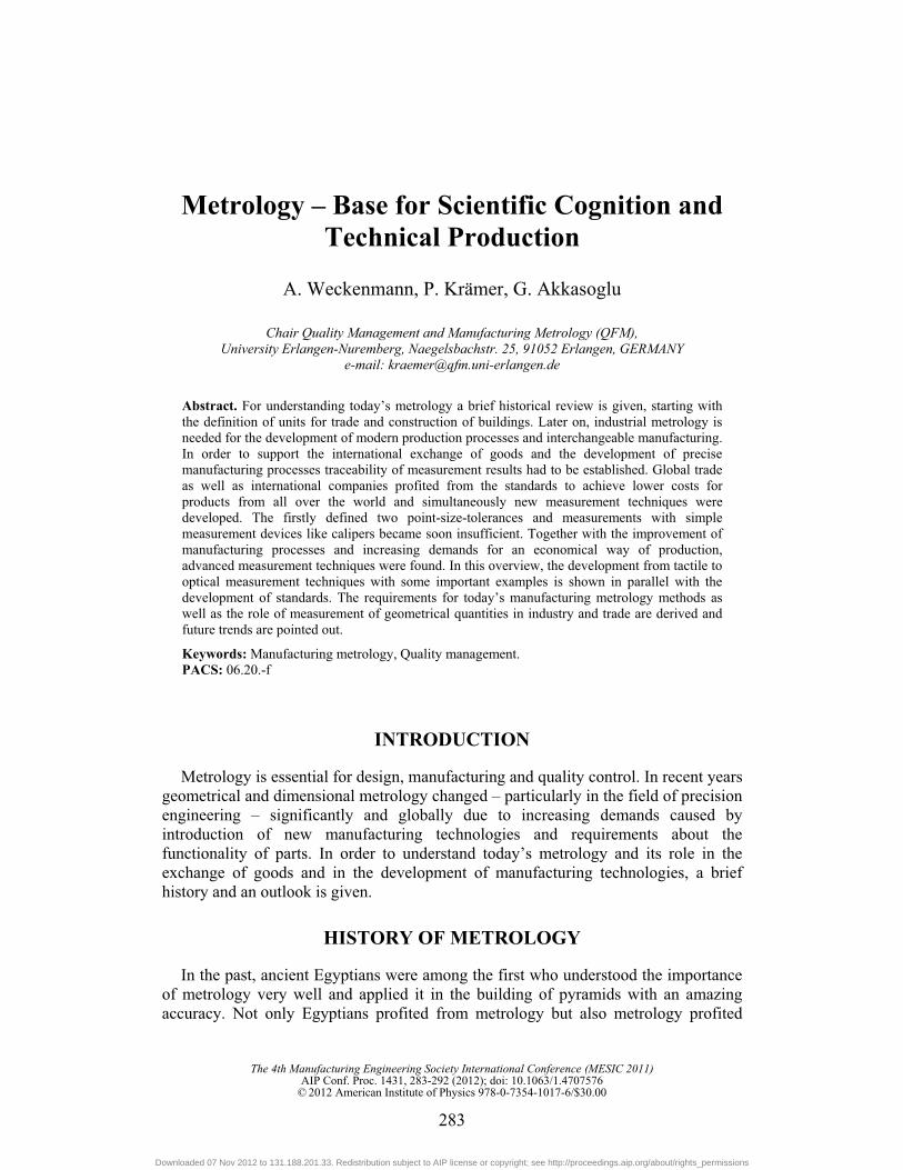
Abstract. For understanding today’s metrology a brief historical review is given, starting with the definition of units for trade and construction of buildings. Later on, industrial metrology is needed for the development of modern production processes and interchangeable manufacturing. In order to support the international exchange of goods and the development of precise manufacturing processes traceability of measurement results had to be established. Global trade as well as international companies profited from the standards to achieve lower costs for products from all over the world and simultaneously new measurement techniques were developed. The firstly defined two point-size-tolerances and measurements with simple measurement devices like calipers became soon insufficient. Together with the improvement of manufacturing processes and increasing demands for an economical way of production, advanced measurement techniques were found. In this overview, the development from tactile to optical measurement techniques with some important examples is shown in parallel with the development of standards. The requirements for today’s manufacturing metrology methods as well as the role of measurement of geometrical quantities in industry and trade are derived and future trends are pointed out.
Keywords: Manufacturing metrology, Quality management. PACS: 06.20.-f
INTRODUCTION
Metrology is essential for design, manufacturing and quality control. In recent years geometrical and dimensional metrology changed – particularly in the field of precision engineering – significantly and globally due to increasing demands caused by introduction of new manufacturing technologies and requirements about the functionality of parts. In order to understand today’s metrology and its role in the exchange of goods and in the development of manufacturing technologies, a brief history and an outlook is given.
HISTORY OF METROLOGY
In the past, ancient Egyptians were among the first who understood the importance of metrology very well and applied it in the building of pyramids with an amazing accuracy. Not only Egyptians profited from metrology but also metrology profited
The 4th Manufacturing Engineering Society International Conference (MESIC 2011)AIP Conf. Proc. 1431, 283-292 (2012); doi: 10.1063/1.4707576
© 2012 American Institute of Physics 978-0-7354-1017-6/$30.00
283
Downloaded 07 Nov 2012 to 131.188.201.33. Redistribution subject to AIP license or copyright; see http://proceedings.aip.org/about/rights_permissions
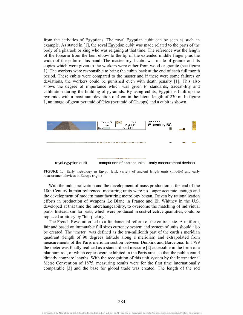
from the activities of Egyptians. The royal Egyptian cubit can be seen as such an example. As stated in [1], the royal Egyptian cubit was made related to the parts of the body of a pharaoh or king who was reigning at that time. The reference was the length of the forearm from the bent elbow to the tip of the extended middle finger plus the width of the palm of his hand. The master royal cubit was made of granite and its copies which were given to the workers were either from wood or granite (see figure 1). The workers were responsible to bring the cubits back at the end of each full month period. These cubits were compared to the master and if there were some failures or deviations, the workers could be punished even with death penalty [1]. This also shows the degree of importance which was given to standards, traceability and calibration during the building of pyramids. By using cubits, Egyptians built up the pyramids with a maximum deviation of 4 cm in the lateral length of 230 m. In figure 1, an image of great pyramid of Giza (pyramid of Cheops) and a cubit is shown.
FIGURE 1. Early metrology in Egypt (left), variety of ancient length units (middle) and early measurement devices in Europe (right)
With the industrialization and the development of mass production at the end of the
18th Century human referenced measuring units were no longer accurate enough and the development of modern manufacturing metrology began. Driven by rationalization efforts in production of weapons Le Blanc in France and Eli Whitney in the U.S. developed at that time the interchangeability, to overcome the matching of individual parts. Instead, similar parts, which were produced in cost-effective quantities, could be replaced arbitrary by "bin-picking".
The French Revolution led to a fundamental reform of the entire state. A uniform, fair and based on immutable full sizes currency system and system of units should also be created. The “meter” was defined as the ten-millionth part of the earth’s meridian quadrant (length of 90 degrees latitude along a meridian) and extrapolated from measurements of the Paris meridian section between Dunkirk and Barcelona. In 1799 the meter was finally realized as a standardized measure [2] accessible in the form of a platinum rod, of which copies were exhibited in the Paris area, so that the public could directly compare lengths. With the recognition of this unit system by the International Metre Convention of 1875, measuring results were for the first time internationally comparable [3] and the base for global trade was created. The length of the rod
284
Downloaded 07 Nov 2012 to 131.188.201.33. Redistribution subject to AIP license or copyright; see http://proceedings.aip.org/about/rights_permissions
(“standard meter”) embodied the length unit “meter”, which has been passed on to national metrology institutes.
Further developments in the field of manufacturing technology improved the precision of products and demanded a more precise definition of the unit of length. By redefining the unit of length “meter” as a multiple of the wavelength of a particular krypton radiation, the unit could be reproduced more accurately. After the development of the laser in 1983 the unit of length was defined by the speed of light as the length of distance that was covered by light in vacuum during a period of 1/299792458 seconds. The unit of length is no longer defined by a prototype, which is subjected to aging and environmental changes, but can nowadays directly traced back to the natural constant “speed of light”. In this way the length of unit depends on the time unit “second” and the time measurement and can be determined more accurately by several orders of magnitude.
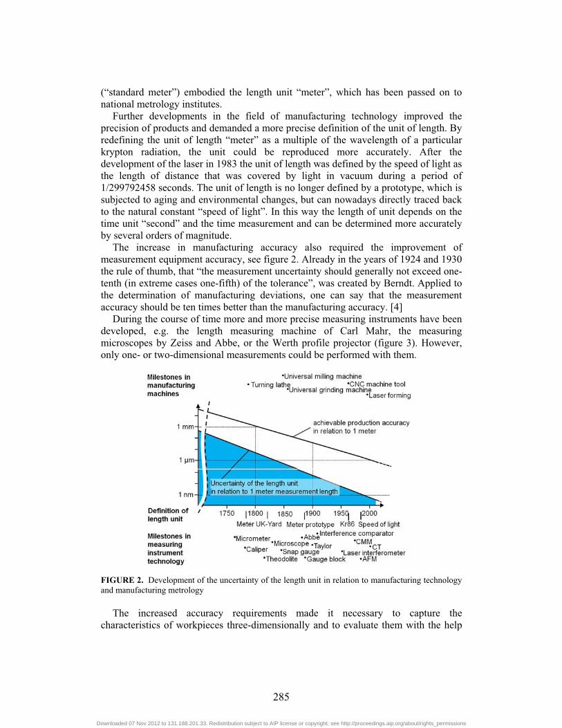
The increase in manufacturing accuracy also required the improvement of measurement equipment accuracy, see figure 2. Already in the years of 1924 and 1930 the rule of thumb, that “the measurement uncertainty should generally not exceed one-tenth (in extreme cases one-fifth) of the tolerance”, was created by Berndt. Applied to the determination of manufacturing deviations, one can say that the measurement accuracy should be ten times better than the manufacturing accuracy. [4]
During the course of time more and more precise measuring instruments have been developed, e.g. the length measuring machine of Carl Mahr, the measuring microscopes by Zeiss and Abbe, or the Werth profile projector (figure 3). However, only one- or two-dimensional measurements could be performed with them.
FIGURE 2. Development of the uncertainty of the length unit in relation to manufacturing technology and manufacturing metrology
The increased accuracy requirements made it necessary to capture the
characteristics of workpieces three-dimensionally and to evaluate them with the help
285
Downloaded 07 Nov 2012 to 131.188.201.33. Redistribution subject to AIP license or copyright; see http://proceedings.aip.org/about/rights_permissions
of form and position tolerances. Thinking in terms of coordinates began with the growing application of drilling machines, in which the position of the drills to be manufactured was given by coordinates. In measuring one was long time tempted to keep the familiar two-point measurements. Reference planes were defined implicitly by the contact surface of the workpiece on the measuring plate and the coordinate system was realized by “rotating and turning” of the workpiece. Under high expenditure of time only few measuring points could be acquired.
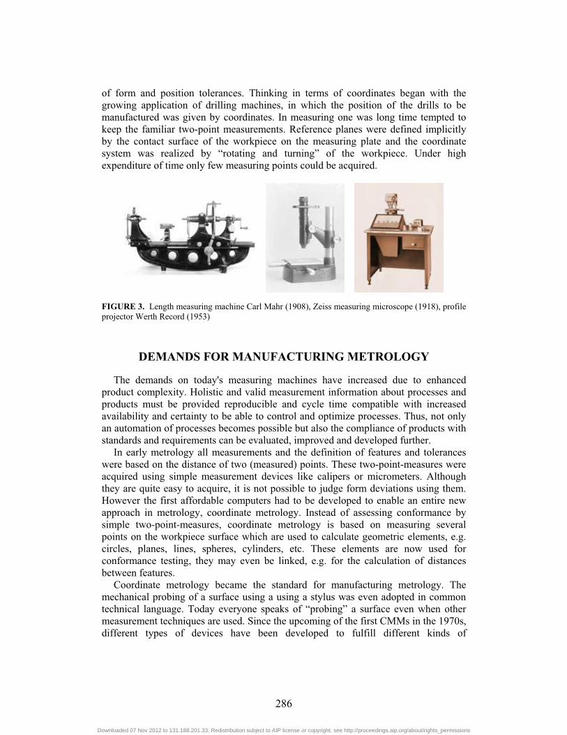
FIGURE 3. Length measuring machine Carl Mahr (1908), Zeiss measuring microscope (1918), profile projector Werth Record (1953)
DEMANDS FOR MANUFACTURING METROLOGY
The demands on today's measuring machines have increased due to enhanced product complexity. Holistic and valid measurement information about processes and products must be provided reproducible and cycle time compatible with increased availability and certainty to be able to control and optimize processes. Thus, not only an automation of processes becomes possible but also the compliance of products with standards and requirements can be evaluated, improved and developed further.
In early metrology all measurements and the definition of features and tolerances were based on the distance of two (measured) points. These two-point-measures were acquired using simple measurement devices like calipers or micrometers. Although they are quite easy to acquire, it is not possible to judge form deviations using them. However the first affordable computers had to be developed to enable an entire new approach in metrology, coordinate metrology. Instead of assessing conformance by simple two-point-measures, coordinate metrology is based on measuring several points on the workpiece surface which are used to calculate geometric elements, e.g. circles, planes, lines, spheres, cylinders, etc. These elements are now used for conformance testing, they may even be linked, e.g. for the calculation of distances between features.
Coordinate metrology became the standard for manufacturing metrology. The mechanical probing of a surface using a using a stylus was even adopted in common technical language. Today everyone speaks of “probing” a surface even when other measurement techniques are used. Since the upcoming of the first CMMs in the 1970s, different types of devices have been developed to fulfill different kinds of
286
Downloaded 07 Nov 2012 to 131.188.201.33. Redistribution subject to AIP license or copyright; see http://proceedings.aip.org/about/rights_permissions
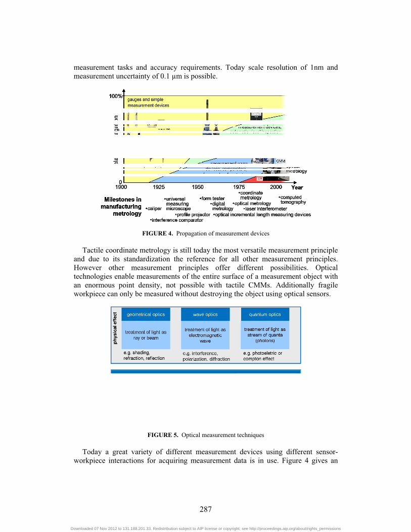
measurement tasks and accuracy requirements. Today scale resolution of 1nm and measurement uncertainty of 0.1 μm is possible.
FIGURE 4. Propagation of measurement devices Tactile coordinate metrology is still today the most versatile measurement principle
and due to its standardization the reference for all other measurement principles. However other measurement principles offer different possibilities. Optical technologies enable measurements of the entire surface of a measurement object with an enormous point density, not possible with tactile CMMs. Additionally fragile workpiece can only be measured without destroying the object using optical sensors.
FIGURE 5. Optical measurement techniques Today a great variety of different measurement devices using different sensor-
workpiece interactions for acquiring measurement data is in use. Figure 4 gives an
287
Downloaded 07 Nov 2012 to 131.188.201.33. Redistribution subject to AIP license or copyright; see http://proceedings.aip.org/about/rights_permissions
example of the propagation of devices in use in the past and in the present. Even simple gauges and measurement devices are still widely used due to their ease of use and their robustness even under harsh conditions in the shop floor.
STATE OF THE ART
Today an enormous variety of sensors for surface determination is used. Figure 5 shows a classification of optical sensors used for different purpose in manufacturing metrology.
Fringe projection
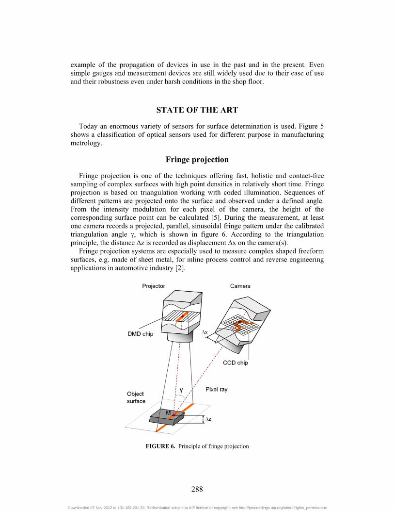
Fringe projection is one of the techniques offering fast, holistic and contact-free sampling of complex surfaces with high point densities in relatively short time. Fringe projection is based on triangulation working with coded illumination. Sequences of different patterns are projected onto the surface and observed under a defined angle. From the intensity modulation for each pixel of the camera, the height of the corresponding surface point can be calculated [5]. During the measurement, at least one camera records a projected, parallel, sinusoidal fringe pattern under the calibrated triangulation angle �, which is shown in figure 6. According to the triangulation principle, the distance �z is recorded as displacement �x on the camera(s).
Fringe projection systems are especially used to measure complex shaped freeform surfaces, e.g. made of sheet metal, for inline process control and reverse engineering applications in automotive industry [2].
FIGURE 6. Principle of fringe projection
288
Downloaded 07 Nov 2012 to 131.188.201.33. Redistribution subject to AIP license or copyright; see http://proceedings.aip.org/about/rights_permissions
Chromatic white light sensor
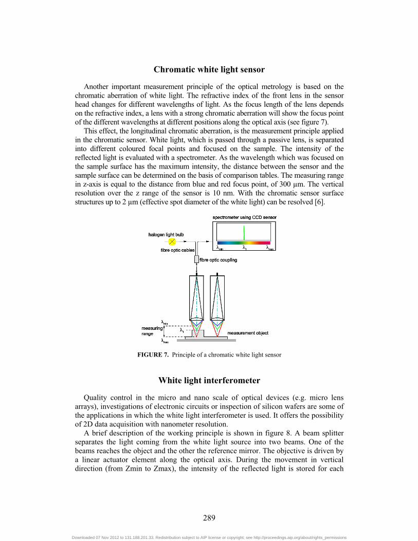
Another important measurement principle of the optical metrology is based on the chromatic aberration of white light. The refractive index of the front lens in the sensor head changes for different wavelengths of light. As the focus length of the lens depends on the refractive index, a lens with a strong chromatic aberration will show the focus point of the different wavelengths at different positions along the optical axis (see figure 7).
This effect, the longitudinal chromatic aberration, is the measurement principle applied in the chromatic sensor. White light, which is passed through a passive lens, is separated into different coloured focal points and focused on the sample. The intensity of the reflected light is evaluated with a spectrometer. As the wavelength which was focused on the sample surface has the maximum intensity, the distance between the sensor and the sample surface can be determined on the basis of comparison tables. The measuring range in z-axis is equal to the distance from blue and red focus point, of 300 μm. The vertical resolution over the z range of the sensor is 10 nm. With the chromatic sensor surface structures up to 2 μm (effective spot diameter of the white light) can be resolved [6].
FIGURE 7. Principle of a chromatic white light sensor
White light interferometer
Quality control in the micro and nano scale of optical devices (e.g. micro lens arrays), investigations of electronic circuits or inspection of silicon wafers are some of the applications in which the white light interferometer is used. It offers the possibility of 2D data acquisition with nanometer resolution.
A brief description of the working principle is shown in figure 8. A beam splitter separates the light coming from the white light source into two beams. One of the beams reaches the object and the other the reference mirror. The objective is driven by a linear actuator element along the optical axis. During the movement in vertical direction (from Zmin to Zmax), the intensity of the reflected light is stored for each
289
Downloaded 07 Nov 2012 to 131.188.201.33. Redistribution subject to AIP license or copyright; see http://proceedings.aip.org/about/rights_permissions
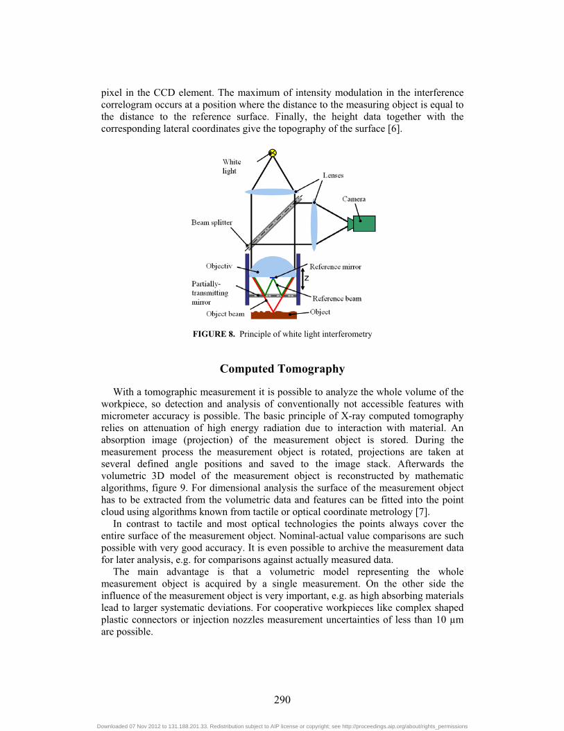
pixel in the CCD element. The maximum of intensity modulation in the interference correlogram occurs at a position where the distance to the measuring object is equal to the distance to the reference surface. Finally, the height data together with the corresponding lateral coordinates give the topography of the surface [6].
FIGURE 8. Principle of white light interferometry
Computed Tomography
With a tomographic measurement it is possible to analyze the whole volume of the workpiece, so detection and analysis of conventionally not accessible features with micrometer accuracy is possible. The basic principle of X-ray computed tomography relies on attenuation of high energy radiation due to interaction with material. An absorption image (projection) of the measurement object is stored. During the measurement process the measurement object is rotated, projections are taken at several defined angle positions and saved to the image stack. Afterwards the volumetric 3D model of the measurement object is reconstructed by mathematic algorithms, figure 9. For dimensional analysis the surface of the measurement object has to be extracted from the volumetric data and features can be fitted into the point cloud using algorithms known from tactile or optical coordinate metrology [7].
In contrast to tactile and most optical technologies the points always cover the entire surface of the measurement object. Nominal-actual value comparisons are such possible with very good accuracy. It is even possible to archive the measurement data for later analysis, e.g. for comparisons against actually measured data.
The main advantage is that a volumetric model representing the whole measurement object is acquired by a single measurement. On the other side the influence of the measurement object is very important, e.g. as high absorbing materials lead to larger systematic deviations. For cooperative workpieces like complex shaped plastic connectors or injection nozzles measurement uncertainties of less than 10 μm are possible.
290
Downloaded 07 Nov 2012 to 131.188.201.33. Redistribution subject to AIP license or copyright; see http://proceedings.aip.org/about/rights_permissions
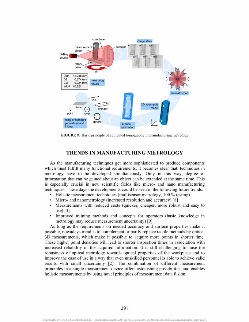
FIGURE 9. Basic principle of computed tomography in manufacturing metrology
TRENDS IN MANUFACTURING METROLOGY
As the manufacturing techniques get more sophisticated to produce components which must fulfill many functional requirements, it becomes clear that, techniques in metrology have to be developed simultaneously. Only in this way, degree of information that can be gained about an object can be extended at the same time. This is especially crucial in new scientific fields like micro- and nano manufacturing techniques. These days the developments could be seen in the following future trends:
• Holistic measurement techniques (multisensor metrology, 100 % testing) • Micro- and nanometrology (increased resolution and accuracy) [8] • Measurements with reduced costs (quicker, cheaper, more robust and easy to
use) [3] • Improved training methods and concepts for operators (basic knowledge in
metrology may reduce measurement uncertainty) [9] As long as the requirements on needed accuracy and surface properties make it
possible, nowadays trend is to complement or partly replace tactile methods by optical 3D measurements, which make it possible to acquire more points in shorter time. These higher point densities will lead to shorter inspection times in association with increased reliability of the acquired information. It is still challenging to raise the robustness of optical metrology towards optical properties of the workpiece and to improve the ease of use in a way that even unskilled personnel is able to achieve valid results with small uncertainty [2]. The combination of different measurement principles in a single measurement device offers astonishing possibilities and enables holistic measurements by using novel principles of measurement data fusion.
291
Downloaded 07 Nov 2012 to 131.188.201.33. Redistribution subject to AIP license or copyright; see http://proceedings.aip.org/about/rights_permissions
CONCLUSION AND OUTLOOK
Measurements are the key of any progress in natural sciences and the substantial prerequisite of every engineering development. But in most of the industrial applications, manufacturing metrology is seen as a major cost factor which has to be minimized. However it should be kept in mind, that if the required accuracy is not maintained, it is possible to make false decisions. The risk of false decision–making increases with coarser sampling and higher measurement uncertainties. From the economic point of view, the costs of testing have to be balanced against the costs deriving from false decisions [10]. It is required to know, how much information is needed about a product or a process in order to make sure that the functional requirements are ensured.
The developments in metrology make it possible to extend the application of optical, robust and shopfloor-suitable methods with increased accuracy. But to ensure the maximum significance of measurement results, global traceability and uniform strategies for measurement uncertainty evaluation should be simultaneously developed.
REFERENCES
1. J. L. Bucher, “The metrology handbook”, 1st ed., ASQ Quality Press, 2004. 2. H. Peitgen, H. Jürgens, D. Saupe, Chaos and fractals: new frontiers of science, 2nd ed., Berlin:
Springer, 2004. 3. A. Weckenmann, P. Kraemer, J. Hoffmann, “Manufacturing metrology –State of art and prospects”,
in Proc. ISMQC, Madras (INDIA), 2007, pp. 1-8. 4. G. Berndt, E. Hultzsch, H. Weinhold, Wissenschaftliche Zeitschrift der Technischen Universität
Dresden 17, S. 465(1968). 5. A. Weckenmann, J. Weickmann, W. Hartmann, Proceedings of SPIE 7102, pp. 1-12 (2008). 6. A. Weckenmann, Ö. Tan, “Optical topography measurements in manufacturing metrology” in Proc.
Dies/Molds 2009, edited by B. Kaftanoglu et al., Kusadasi (TURKEY), 2009, pp. 297-302. 7. A. Weckenmann, P. Kraemer, Key Engineering Materials 437, pp. 73-78 (2010). 8. A. Weckenmann, X. Jiang, K.-D. Sommer, U. Neuschaefer-Rube, J. Seewig, L. Shaw, T. Estler,
CIRP Annals - Manufacturing Technology 58, p. 701-721 (2009). 9. T. Werner, A. Weckenmann, “Sustainable quality assurance by assuring competence of employees”
in Book of Abstracts ISMQC 2010, Tokyo (JAPAN), 2010, p. 115. 10. A. Dietlmaier, A. Weckenmann, “Economic Efficiency in Metrology” in Proc. QIEM 2011, Cluj-
Napoca (ROMANIA), 2011, pp. 57-62.
292
Downloaded 07 Nov 2012 to 131.188.201.33. Redistribution subject to AIP license or copyright; see http://proceedings.aip.org/about/rights_permissions