Embed Size (px)
Citation preview
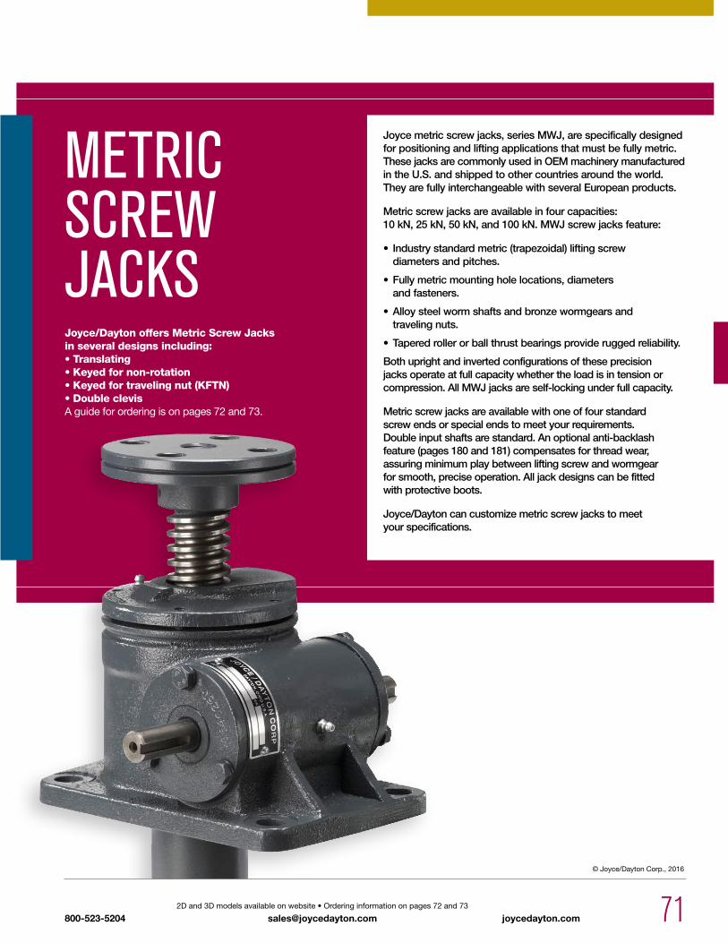
mETRiC SCREw JACKS
Joyce metric screw jacks, series MWJ, are specifically designed for positioning and lifting applications that must be fully metric. These jacks are commonly used in OEM machinery manufactured in the U.S. and shipped to other countries around the world. They are fully interchangeable with several European products.
Metric screw jacks are available in four capacities: 10 kN, 25 kN, 50 kN, and 100 kN. MWJ screw jacks feature:
• Industry standard metric (trapezoidal) lifting screwdiameters and pitches.
• Fully metric mounting hole locations, diametersand fasteners.
• Alloy steel worm shafts and bronze wormgears andtraveling nuts.
• Tapered roller or ball thrust bearings provide rugged reliability.
Both upright and inverted configurations of these precision jacks operate at full capacity whether the load is in tension or compression. All MWJ jacks are self-locking under full capacity.
Metric screw jacks are available with one of four standard screw ends or special ends to meet your requirements. Double input shafts are standard. An optional anti-backlash feature (pages 180 and 181) compensates for thread wear, assuring minimum play between lifting screw and wormgear for smooth, precise operation. All jack designs can be fitted with protective boots.
Joyce/Dayton can customize metric screw jacks to meet your specifications.
Joyce/Dayton offers Metric Screw Jacks in several designs including:• Translating• Keyed for non-rotation• Keyed for traveling nut (KFTN)• Double clevisAguidefororderingisonpages72and73.
71800-523-52042Dand3Dmodelsavailableonwebsite•Orderinginformationonpages72and73
[email protected] joycedayton.com
© Joyce/Dayton Corp., 2016

72
mETRiC SCREw JACKS ORDERiNg iNFORmATiON
joycedayton.com Customproductsareavailable•ContactJoyce/Daytonwithyourrequirements
[email protected] 800-523-5204
U=Upright I=Inverted
1=T1 (plain end)
2=T2(load pad)
3=T3(threaded end)
4=T4(male clevis)
Sample part Number: mwJ65u2S-300–STDX–STDX-B
*Contact Joyce/Dayton with your requirements.
Jack Configuration
End Conditions
Additional OptionsX=Standard Jack, no additional options
S=Additional Specification Required (comment as necessary)
Anti-Backlash p. 180A=Split NutA90=A90 DesignA95=A95 Design
Protective Boots pp. 170-172B=Protective BootD=Dual Protective Boot
Finishes p. 179F1=Do Not PaintF2=Epoxy PaintF3=Outdoor Paint Process
Motor OptionsM1=Less MotorM2=Brake MotorM3=Single Phase Motor (120VAC)M4=50Hz Motor
Grease/SealsH1=High Temperature OperationH2=Food Grade
Screw StopsST0=ExtendingST1=Retracting ST2=Both
• Specify as many options as needed
Left Side Shaft Code (see below)
XXXX=RemoveSTDX=Standard
For optional shaft codes, see page 73.
Right Side Shaft Code (see below)
XXXX=RemoveSTDX=Standard
For optional shaft codes, see page 73.
Jack Designs
S=Translating K=Keyed for Non Rotation
N=Traveling Nut D=Double Clevis* A=KFTN Trunnion* T=Trunnion*
Metric Screw Jack RiseRise is travel expressed in millimeters and not the actual screw length.
Instructions: Select a model number from this chart.
10 kN 25 kN 50 kN 100 kNmwJ51mwJ201
mwJ62.5mwJ122.5mwJ242.5
mwJ65mwJ125mwJ245
mwJ810mwJ2410
73
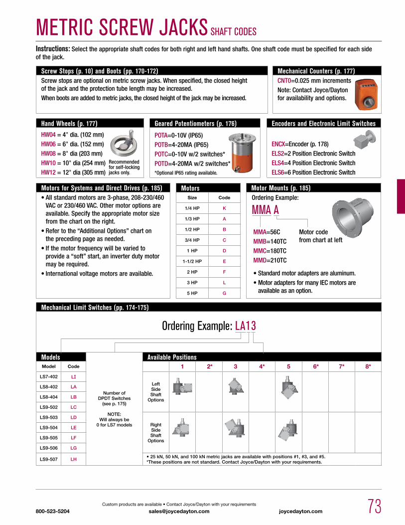
mETRiC SCREw JACKS ShAFT CODES
800-523-5204Customproductsareavailable•ContactJoyce/Daytonwithyourrequirements
[email protected] joycedayton.com
Motor Mounts (p. 185)
Instructions: Select the appropriate shaft codes for both right and left hand shafts. One shaft code must be specified for each side of the jack.
Ordering Example:
mmA A
•Standardmotoradaptersarealuminum.•MotoradaptersformanyIECmotorsare available as an option.
MMA=56CMMB=140TCMMC=180TCMMD=210TC
MotorsSize Code
1/4 HP K
1/3 HP A
1/2 HP B
3/4 HP C
1 HP D
1-1/2 HP E
2 HP F
3 HP L
5 HP G
Mechanical Limit Switches (pp. 174-175)
Ordering Example: LA13
Models
Number of DPDT Switches
(see p. 175)
NOTE: Will always be
0 for LS7 models
Available PositionsModel Code 1 2* 3 4* 5 6* 7* 8*
LS7-402 LILeft Side Shaft
Options
LS8-402 LA
LS8-404 LB
LS9-502 LC
LS9-503 LD
Right Side Shaft
Options
LS9-504 LE
LS9-505 LF
LS9-506 LG
LS9-507 LH • 25 kN, 50 kN, and 100 kN metric jacks are available with positions #1, #3, and #5.*These positions are not standard. Contact Joyce/Dayton with your requirements.
Screw Stops (p. 10) and Boots (pp. 170-172)Screw stops are optional on metric screw jacks. When specified, the closed height of the jack and the protection tube length may be increased. When boots are added to metric jacks, the closed height of the jack may be increased.
Mechanical Counters (p. 177)CNT0=0.025 mm incrementsNote: Contact Joyce/Dayton for availability and options.
Encoders and Electronic Limit Switches
ENCX=Encoder (p. 178)ELS2=2 Position Electronic SwitchELS4=4 Position Electronic SwitchELS6=6 Position Electronic Switch
Geared Potentiometers (p. 176)
POTA=0-10V (IP65)POTB=4-20MA (IP65)POTC=0-10V w/2 switches*POTD=4-20MA w/2 switches**Optional IP65 rating available.
Hand Wheels (p. 177)
HW04 = 4" dia. (102 mm)HW06 = 6" dia. (152 mm)HW08 = 8"dia(203mm)HW10 = 10" dia (254 mm)HW12 = 12"dia(305mm)
Motors for Systems and Direct Drives (p. 185)•Allstandardmotorsare3-phase,208-230/460VACor230/460VAC.Othermotoroptionsareavailable. Specify the appropriate motor size from the chart on the right.
•Refertothe“AdditionalOptions”charton the preceding page as needed.
•Ifthemotorfrequencywillbevariedto providea“soft”start,aninverterdutymotormayberequired.
•Internationalvoltagemotorsareavailable.
Motor code from chart at left
Recommendedfor self-locking jacks only.
74 joycedayton.com 2Dand3Dmodelsavailableonwebsite•Orderinginformationonpages72and73
[email protected] 800-523-5204
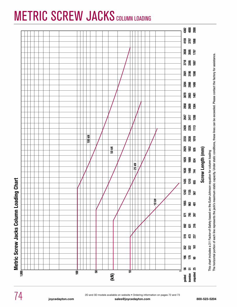
mETRiC SCREw JACKS COLumN LOADiNgM
etric
Scr
ew J
acks
Col
umn
Load
ing
Char
t
(kN)
Scre
w L
engt
h (m
m)
This
cha
rt in
clud
es a
2:1
Fac
tor-o
f-Sa
fety
bas
ed o
n th
e Eu
ler-J
ohns
on e
quat
ion
for c
olum
n lo
adin
g Th
e ho
rizon
tal p
ortio
n of
eac
h lin
e re
pres
ents
the
jack
’s m
axim
um s
tatic
cap
acity
. Und
er s
tatic
con
ditio
ns, t
hese
line
s ca
n be
exc
eede
d. P
leas
e co
ntac
t the
fact
ory
for a
ssis
tanc
e.

75800-523-52042Dand3Dmodelsavailableonwebsite•Orderinginformationonpages72and73
[email protected] joycedayton.com
mETRiC SCREw JACKS SpECiFiCATiONS
Model CapacityScrew
Diameter (mm)
Thread Pitch/Lead
Worm Gear Ratio
Worm Shaft Turns for
1mm Travel
Tare Torque (Nm)
Starting Torque (Nm)
Operating Torque (Nm)
Efficiency Rating % Approx.
Screw Torque (Nm)
Basic Jack Weight
(Kg)
Jack Weight (Kg) per
25mm Travel
mwJ5110kN 20 5mm
5:1 10.33
.95w* .70w* @ 500 Rpm 22.7
2w* 2.7 0.14mwJ201 20:1 4 .41w* .23w*
@ 500 Rpm 17.0
mwJ62.5
25kN 30 6mm
6:1 1
0.67
1.01w* .81w* @ 500 Rpm 19.6
3w* 6.8 0.18mwJ122.5 12:1 2 .62w* .45w* @ 500 Rpm 17.8
mwJ242.5 24:1 4 .44w* .27w* @ 500 Rpm 14.7
mwJ65
50kN 40 9mm
6:1 0.67
1.13
1.64w* 1.14w* @ 300 Rpm 20.9
4w* 14.5 0.32mwJ125 12:1 1.33 1.03w* .64w* @ 300 Rpm 18.7
mwJ245 24:1 2.67 .74w* .39w* @ 300 Rpm 15.2
mwJ810100kN 55 12mm
8:1 0.672.26
1.53w* 1.18w* @ 200 Rpm 20.2
5w* 19.5 0.59mwJ2410 24:1 2 .76w* .49w*
@ 200 Rpm 16.1
*W: Load in kN.Tare Torque: initial torque to overcome seal and normal assembly drag. This value must be added to starting torque or operating torque values.Starting Torque: Torque value required to start moving a given load (dissipates to operating torque values once the load begins moving).Operating Torque: Torque required to continuously raise a given load at the input Rpm listed. Note: if your actual input Rpm is 20% higher or lower than the listed Rpm, please refer to our JAX® program to determine actual torque values at your Rpm.Screw Torque: Torque required to resist screw rotation (Translating Design Jacks) and traveling nut rotation (Keyed for Traveling Nut Design Jacks).Lead: The distance traveled axially in one rotation of the lifting screw.Pitch: The distance from a point on a screw thread to a corresponding point on the next thread measured axially.
76 joycedayton.com 2Dand3Dmodelsavailableonwebsite•Orderinginformationonpages72and73
[email protected] 800-523-5204
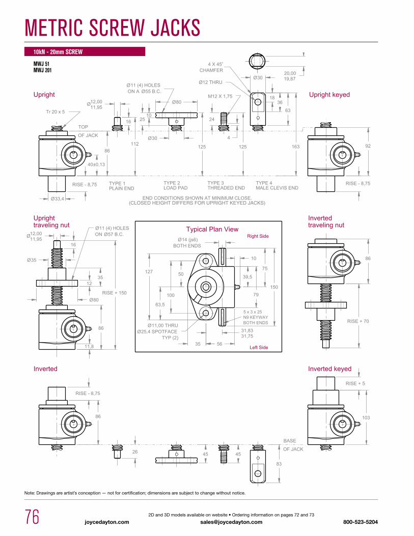
mETRiC SCREw JACKS
Note:Drawingsareartist’sconception—notforcertification;dimensionsaresubjecttochangewithoutnotice.
MWJ 51 MWJ 201
10kN - 20mm SCREW

mETRiC SCREw JACKS
77800-523-52042Dand3Dmodelsavailableonwebsite•Orderinginformationonpages72and73
[email protected] joycedayton.com
Note:Drawingsareartist’sconception—notforcertification;dimensionsaresubjecttochangewithoutnotice.
MWJ 62.5 MWJ 122.5 MWJ 242.5
25kN - 30mm SCREW

mETRiC SCREw JACKS
78 joycedayton.com 2Dand3Dmodelsavailableonwebsite•Orderinginformationonpages72and73
[email protected] 800-523-5204
Note:Drawingsareartist’sconception—notforcertification;dimensionsaresubjecttochangewithoutnotice.
MWJ 65 MWJ 125 MWJ 245
50kN - 40mm SCREW

mETRiC SCREw JACKS
79800-523-52042Dand3Dmodelsavailableonwebsite•Orderinginformationonpages72and73
[email protected] joycedayton.com
Note:Drawingsareartist’sconception—notforcertification;dimensionsaresubjecttochangewithoutnotice.
MWJ 810 MWJ 2410
100kN - 55mm SCREW