Embed Size (px)
Citation preview
Installation and Operation manual
8.4.2016(S/N: 155549/18 Rev.1.0)
INDUCTION RANGES
METOS ARDOX IEC
TYPE: IEC4, IEC6
4210070, 4210073

8.4.2016METOS Ardox IEC
2 |
Table of Contents
1. General .......................................................................................................................................................31.1. Symbols used in the manual .......................................................................................................................31.2. Symbols used on the appliance ...................................................................................................................31.3. Checking the relationship of the appliance and the manual ........................................................................32. Safety .........................................................................................................................................................42.1. Safe use of the appliance ............................................................................................................................42.2. Safety instructions in case of malfunction ...................................................................................................42.3. Disposal of the appliance ............................................................................................................................43. Functional description ..............................................................................................................................53.1. General ........................................................................................................................................................53.2. Application of the appliance ........................................................................................................................53.2.1. Prohibited use .............................................................................................................................................53.3. Construction and operating principle ...........................................................................................................53.3.1. Operating switches and indicator lights ......................................................................................................54. Operation instructions ..............................................................................................................................64.1. Before using the appliance ..........................................................................................................................64.1.1. Selecting cookware for ceramic hobs with infrared heating .......................................................................64.1.2. Selecting cookware for ceramic hobs with induction heating .....................................................................64.1.3. Pot type and Condition guide .....................................................................................................................84.2. Operation procedures ..................................................................................................................................94.2.1. Using the range ...........................................................................................................................................94.2.2. Cooking hints ...............................................................................................................................................94.3.1. Cleaning and Maintenance ........................................................................................................................104.3.2. Other service measures ............................................................................................................................105. Installation ............................................................................................................................................... 115.1. General ...................................................................................................................................................... 115.2. Ambient conditions ................................................................................................................................... 115.3. Storage, transporting and unpacking the range ......................................................................................... 115.4. Positioning the range ................................................................................................................................. 115.5. Electrical connections ................................................................................................................................125.6. Test-run ......................................................................................................................................................126. Trobleshooting .........................................................................................................................................137. Technical specifications ..........................................................................................................................15

| 3
8.4.2016METOS Ardox IEC
1. GeneralCarefully read the instructions in this manual as they contain important information regarding proper, ef-ficient and safe installation, use and maintenance of the appliance.
Keep this manual in a safe place for eventual use by other operators of the appliance.
The installation of this appliance must be carried out in accordance with the manufactur- er’s instructions and following local regulations. The connection of the appliance to the electric and water supply must be carried out by qualified persons only.
Persons using this appliance should be specifically trained in its operation.
Switch off the appliance in case of failure or malfunction. The periodical function checks requested in the manual must be carried out according to the instructions. Have the appli- ance serviced by a technically qualified person authorized by the manufacturer and using original spare parts.
Not complying with the above may put the safety of the appliance in danger.
The manufacturer does not take responsibility for any damages in case the operation in- structions and warnings contained in this manual are neglected.
1.1. Symbols used in the manualThis symbol informs about a situation where a safety risk might be at hand. Given instruc- tions are man-datory in order to prevent injury..
This symbol informs about the right way to perform in order to prevent bad results, appli- ance damage or hazardous situations.
This symbol informs about recommendations and hints that help to get the best perform- ance out of the appliance.
1.2. Symbols used on the applianceThis symbol on a part informs about electrical terminals behind the part. The removal of the part must be carried out by qualified persons only.
1.3. Checking the relationship of the appliance and the manualThe rating plate of the appliance indicates the serial number of the appliance. If the man- uals are miss-ing, it is possible to order new ones from the manufacturer or the local repsentative. When ordering new manuals it is essential to quote the serial number shown on the rating plate
STOP
8.4.2016METOS Ardox IEC
4 |
2. Safety
2.1. Safe use of the applianceBecause the range is a heated appliance that has hot surfaces during normal use, the fol- lowing warn-ings and instructions must be followed in order to avoid burns.
• During long-time operation even the frame surrounding the ceramic hob gets hot.• The cooking zones are hot for a long time after switching them off, although the visible heat radiation
has ended.• For safe handling of cookware on the cooking top, always use heat protective gloves.• Do not leave the range on for long periods totally without supervision.• Do not place aluminium foil and plastic vessels on the hot hob surface.• Metallic objects such as kitchen utensils, cutlery etc.shall not be placed on hob sur- face within induc-
tion heating zones as they could get hot.• Take care when operating induction heating surface, as rings, watches and similar objects worn by
user could get hot when in close proximity to the hob surface.• Users with heart pacemakers should consult their doctor whether they are safe near induction range
or not.
2.2. Safety instructions in case of malfunctionIf the surface of ceramic hob is cracked, immediately disconnect the appliance from the mains
2.3. Disposal of the applianceThe destroying of the appliance when its economical lifetime has been reached may be harmful to en-vironment if not properly handled. Utilization of materials that are reusable is best done by professional personnel specialized in recycling .
STOP
| 5
8.4.2016METOS Ardox IEC
3. Functional description
3.1. GeneralThe Ardox IEC range is an appliance with two different types of heating systems. Two cooking zones are heated by induction power source while another two cooking zones are heated by infrared (radiant) heating elements.
3.2. Application of the applianceThe appliance is intended for preparing various kinds of foodstuffs using cookware. The range can be used for cooking, keeping warm, flambering, roasting etc.
3.2.1. Prohibited use
Use of the appliance for any other purposes than that of mentioned above is prohibited.
Preparing of food directly on the ceramic hob surface without cookware is prohibited
3.3. Construction and operating principleCeramic hob surface of Ardox IEC consists of two hob elements with induction heating source and two hob elements with infrared heating elements. Cooking zones for each hob element are marked on glass ceram-ic surface. Induction cooking zones are marked by squares. Infrared heating zones are marked by circles.
Cookware placed on ceramic hob surface within induction heating zones is heated up by means of electromagnetic field generated by induction heating source. Electromagnetic field influences only the bottom of cookware. Energy transfer stops immediately if cook- ware is taken away from hob surface and starts again when cookware has been placed back on hob surface.
Cookware placed on ceramic hob surface within infrared heating zones is heated up by means of radiant heating elements placed beneath ceramic hob surface.
3.3.1. Operating switches and indicator lights
Each cooking zone is operated by means of stepless power switch. Two power switches for induction heating zones are located on the left side of control panel, and two power switches for infrared heating zones are located on the right side of the control panel.
Above each power switch, there is a green LED indicator. Steady light of indicator means that power switch is on and power is transferred to corresponding heating zone.
To generate power for infrared cooking zone, turn the corresponding switch from “0” po- sition to any position between “1” and “6”. The maximum power is when the switch is in “6” position, and the mini-mum when in “1” position.
To generate power for induction cooking zone, put first cookware within cooking zone and turn corre-sponding switch from “0” position to any position between “1” and “12”. The maximum power is when the switch is in”12” position, and the minimum power when the switch is in “1” position.
STOP
STOP
8.4.2016METOS Ardox IEC
6 |
4. Operation instructions
4.1. Before using the appliance
4.1.1. Selecting cookware for ceramic hobs with infrared heating
Cookware made of stainless steel, aluminium and enamelled steel is best suitable for cooking. Enamel based cast iron cookware can also be used if handled with extra care.
Cookware made of copper, ceramic and glass is not fit for use on ceramic hobs with in- frared heating.
4.1.2. Selecting cookware for ceramic hobs with induction heating
Cookware made from stainless steel with compound multi layer base. The magnetic induction base functions as a part of the hob’s magnetic field. Enamelled steel, cast iron andenamelled cast iron cook- ware is also suitable for induction hobs.
As a rule, all the cookware suitable for induction hobs can be recognised by the mark “induction” on the base of cookware. If there is no mark on a base, it is recommended to usea permanent magnet.The magnet must stick to the bottom of cookware.
The cooking zone with pots diameter of over 120mm will be activated, put will not give the maximum power (5kW). Maximum power will reached with pot diameter 200mm
Cookware made of copper, aluminium, ceramic and glass is not suitable for use on ceramic hobs with induction heating.
Cookware made of stainless steel with base which does not attract a permanent magnet is not suitable for use on ceramic hobs with induction heating.
To get the best benefit from the range as well as from cookware please observe the following rules:
• Always lift cookware, do not drag• Use good quality flat-based cookware• Wait for pans to cool before put it in cold water• Always ensure cookware has clean, dry base before use• Ensure cookware handles are positioned safely and away from heat sources• Always use lids except when frying• Ensure cookware matches the size of cooking zone where possible• Remember good quality cookware retain heat well, so generally, only low or medium heat is ne-
cessary.
Guide to the correct use of pans and cooking zones is provided on pages 7 and 8.
| 7
8.4.2016METOS Ardox IEC
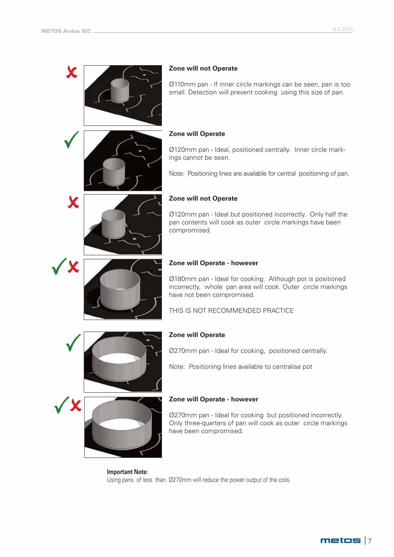
Zone will not Operate
Ø110mm pan - If inner circle markings can be seen, pan is toosmall. Detection will prevent cooking using this size of pan.
Important Note:Using pans of less than Ø270mm will reduce the power output of the coils.
Zone will Operate
Ø120mm pan - Ideal, positioned centrally. Inner circle mark-ings cannot be seen.
Note: Positioning lines are available for central positioning of pan.
Zone will not Operate
Ø120mm pan - Ideal but positioned incorrectly. Only half the pan contents will cook as outer circle markings have been compromised.
Zone will Operate - however
Ø180mm pan - Ideal for cooking. Although pot is positioned incorrectly, whole pan area will cook. Outer circle markings have not been compromised.
THIS IS NOT RECOMMENDED PRACTICE
Zone will Operate
Ø270mm pan - Ideal for cooking, positioned centrally.
Note: Positioning lines available to centralise pot
Zone will Operate - however
Ø270mm pan - Ideal for cooking but positioned incorrectly. Only three-quarters of pan will cook as outer circle markings have been compromised.
8.4.2016METOS Ardox IEC
8 |
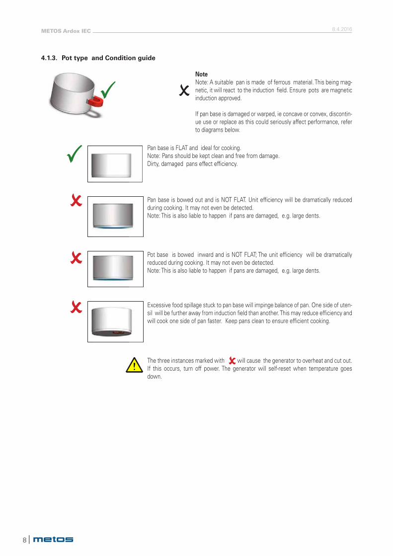
4.1.3. Pot type and Condition guide
NoteNote: A suitable pan is made of ferrous material. This being mag-netic, it will react to the induction field. Ensure pots are magnetic induction approved.
If pan base is damaged or warped, ie concave or convex, discontin-ue use or replace as this could seriously affect performance, refer to diagrams below.
Pan base is FLAT and ideal for cooking. Note: Pans should be kept clean and free from damage. Dirty, damaged pans effect efficiency.
Pan base is bowed out and is NOT FLAT. Unit efficiency will be dramatically reduced during cooking. It may not even be detected.Note: This is also liable to happen if pans are damaged, e.g. large dents.
Pot base is bowed inward and is NOT FLAT; The unit efficiency will be dramatically reduced during cooking. It may not even be detected.Note: This is also liable to happen if pans are damaged, e.g. large dents.
Excessive food spillage stuck to pan base will impinge balance of pan. One side of uten-sil will be further away from induction field than another. This may reduce efficiency and will cook one side of pan faster. Keep pans clean to ensure efficient cooking.
The three instances marked with will cause the generator to overheat and cut out.If this occurs, turn off power. The generator will self-reset when temperature goes down.
| 9
8.4.2016METOS Ardox IEC
4.2. Operation procedures
4.2.1. Using the range
Ardox IEC range with ceramic hobs heats up very fast, so no preheating is necessary.
Infrared cooking zones:
Select cooking zone according to cookware to be applied and food to be prepared. Start cooking from position “6” and when boiling begins, decrease the power as needed. Cook- ware should be placed on the centre of heating zone, otherwise the bottom is heated un- evenly.
Despite the fact that infrared heating elements are equipped with temperature limiters, the cooking zones should not be left without a pan for a long period. If the set power of cooking zone exceeds the heat reception capability of the pan, the temperature limiter would adjust the power as needed.
Induction cooking zones:
To generate power for induction cooking zone, put first cookware within cooking zone and turn corre-sponding switch from “0” position to any position between “1” and “12”. The maximum power is when the switch is in”12” position and the minimum power when the switch is in “1” position.
Induction heating zones are also controlled by temperature sensor. Overheated pans (hot oil, empty pans) can be detected and energy transfer will be stopped. The induction zones must be restarted after they have cooled down.
If there is a long interruption in the electricity supply, all power switches of the range should be set to “0” position. This should be done to prevent unexpected start up of the range when electricity supply is restored.
4.2.2. Cooking hints
1. Before use, ensure hob surface is clean, dry and free of grease. Remove any burnt on food debris.2. Familiarise yourself with cooking area and control settings.3. Each cooking zone has a power capacity of 5kW.4. Each zone is governed by individual energy regulator.5. Control setting is from 1 to 12. (1 - lowest setting, 12 - highest).6. Boiling, steaming, poaching, stewing, pot roasting, deep and shallow frying can be achieved on the hob.7. Ferritic cooking vessels must be used.8. To boil liquid, follow this procedure:• Fill and position pan centrally within cooking zone.• Turn appropriate switch dial to 12.• When boiling occurs, reduce setting and continue to cook by simmering.9. The lower setting is dependent on amount and density of liquid and also starch content.10. Skill is required to control simmering and the ability to select a corresponding temperature setting
will improve with practice.11. Any spillage should be cleaned from hob surface as soon as practically possible.12. Setting for roasting is from 6 to 8. Higher power may cause burning of the food
Failure to clean filter regularly may cause problems that will not be covered by warranty. The air intake filter MUST ALWAYS be in place during operation.
Wipe glass-ceramic hob clean using a damp cloth and warm, soapy water. For heavy stains, use a scraper while cooking zone is still warm.Wipe down with a damp cloth when zone is cool.
STOP
8.4.2016METOS Ardox IEC
10 |
4.3. After use
4.3.1. Cleaning and Maintenance
Use of water hose or pressure cleaning jet is strictly forbidden.
When cleaning the ceramic hob surface, remember that it is hot for a long time after use.
Ceran-glass HobClean glass with hot soapy water and a soft cloth. Do NOT use metal scrapers.The cleaning of ceramic hob surface is identical to cleaning of other similar surfaces like glass.Do not use corrosive or abrasive agents such as grill-and oven-sprays, stain- and rust removers, scouring powder and rough sponges. Cleaning is much easier if possible spill-overs are removed immediately with damp cloth.
Sugar and mixes containing much sugar must be removed immediately, because later removing is labori-ous and may leave permanent marks.
Burned spillovers are easy to remove with a scrapper especially intended for cleaning ceramic hob sur-faces.
If plastic or aluminum foils melt on the ceramic hob surface, they can be also removed with a scraper. For cleaning always prefer chemical cleaning methods rather than mechanical rubbing. Use a slightly alkaline detergent (pH 8-10) diluted in water according to instructions when cleaning the surfaces of the range.
The grease filter protecting air intake in the bottom of the unit must be cleaned regularly. A clogged grease filter can cause overheating, power reduction or even malfunction.
Stainless Steel SurfacesThese surfaces should be cleaned with hot water and detergent then dried and polished with a soft cloth.
Cleaning agents containing bleach, abrasives or caustic chemicals will damage or stain the stainless steel surfaces and must not be used.
Badly stained, removable parts should be soaked in hot water with an approved detergent.If parts are not able to be removed, the application of warm water with approved detergent using nylon or scotch cleaning pads will provide good result.
4.3.2. Other service measures
The appliance does not include any user serviceable parts inside. Service must be done by authorised service personnel only.
STOP
STOP
| 11
8.4.2016METOS Ardox IEC
5. Installation
5.1. GeneralThe installation of this appliance must be carried out in accordance with the manufactur-er’s instructions and in compliance with local rules and regulations. These instructions must be used together with the installation drawing of the appliance.
The connection of the appliance to the electrical and water supply must be carried out by qualified persons only.
5.2. Ambient conditionsThis appliance is intended to be used in the following ambient conditions:
Max.ambient temperature:
• Storage: -20º C...+70º C• Use: +0º C...+40º C
Relative humidity: 10% to 90% non - condensing
5.3. Storage, transporting and unpacking the rangeIt is recommended to keep appliance in its own package before the actual installation begins. It protectsappliance from outer damages. If it is necessary to unpack appliance, possible lifting must be done from the bottom frame using suitable spacers of wood.
In order to avoid damages it is not allowed to use ceramic hob surface as a workbench during installation.
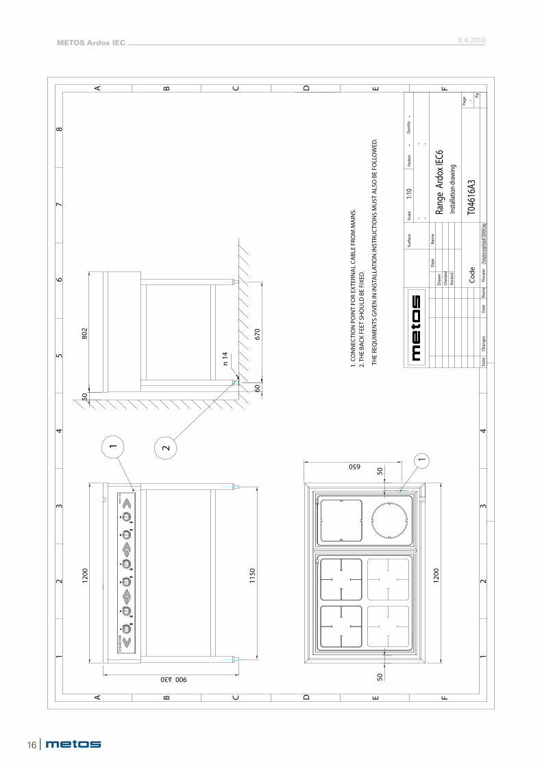
5.4. Positioning the rangeThis appliance is equipped with its own internal cooling system. Air inlet is located on the bottom of stainless steel enclosure (see installation drawing).
Air outlet openings are on the rear side of enclosure. Temperature of intake air should be below 40°C.
This appliance can not be placed direct near ovens or other heating appliances where ambient tempera-ture may reach over 40°C.
An optimum air intake must not be reduced by the installation. Pay attention that air ventilation is avai-lable, see installation drawing min 50 mm from the wall. The grease filter must always be in place when the range is used.When the range is in the right place, it must be leveled in horizontal position by turning adjustable legs. After that, the rear legs must be fixed to the floor by means of flanges and anchor bolts (see installation drawing).
STOP
STOP
8.4.2016METOS Ardox IEC
12 |
5.5. Electrical connectionsCheck and ensure that supply voltage is the same as the voltage given on the rating plate of the appli-ance.
The electrical connections must satisfy local house installation regulations. The valid national and local regulations of the electricity-supply inspection must be observed.
To make eventual future service easier and increase safety, a mains switch must be installed near the appliance. This switch must disconnect the appliance completely from an electrical supply network.
The feed-through for the supply cable is located at the bottom of the range in the right front corner. To connect the supply cable to the terminal, do the following:
• Open ceramic hob and fix it by the fixing rod. The fixing rod is on the left side inside the enclosure• Connect supply cable to the terminal. The terminal is on the right side inside the enclosure• To assemble appliance, carry out operations described above in opposite order
Before close the ceramic hob, check that no wires inside the range get jammed.
5.6. Test-runPlease read the user manual before testing the appliance. After connecting the supply cable, check the function of the range.
Use cookware suitable for induction cooking. Diameter of the bottom of cookware should be at least120 mm.
• Put some water inside cookware and place the latter in the centre of selected cooking zone• Turn corresponding knob from “0”position to any position between “1” and “12.” Green indicator LED
above the knob will be active and water will be heated• Take cookware away from cooking zone, indicator light will be flashing• Place cookware back on the heating area, indicator light will be active again and heating process will
be continued• Adjust to maximum power.• After a few minutes the fan must switch on.• Turn the knob to “0”position. Heating will be stopped and indicator light will be off
STOP
| 13
8.4.2016METOS Ardox IEC
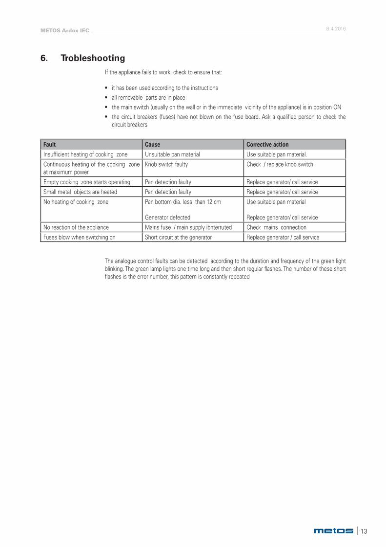
6. TrobleshootingIf the appliance fails to work, check to ensure that:
• it has been used according to the instructions• all removable parts are in place• the main switch (usually on the wall or in the immediate vicinity of the appliance) is in position ON• the circuit breakers (fuses) have not blown on the fuse board. Ask a qualified person to check the
circuit breakers
Fault Cause Corrective action
Insufficient heating of cooking zone Unsuitable pan material Use suitable pan material.
Continuous heating of the cooking zone at maximum power
Knob switch faulty Check / replace knob switch
Empty cooking zone starts operating Pan detection faulty Replace generator/ call service
Small metal objects are heated Pan detection faulty Replace generator/ call service
No heating of cooking zone Pan bottom dia. less than 12 cm
Generator defected
Use suitable pan material
Replace generator/ call service
No reaction of the appliance Mains fuse / main supply ibnterruted Check mains connection
Fuses blow when switching on Short circuit at the generator Replace generator / call service
The analogue control faults can be detected according to the duration and frequency of the green light blinking. The green lamp lights one time long and then short regular flashes. The number of these short flashes is the error number, this pattern is constantly repeated
8.4.2016METOS Ardox IEC
14 |
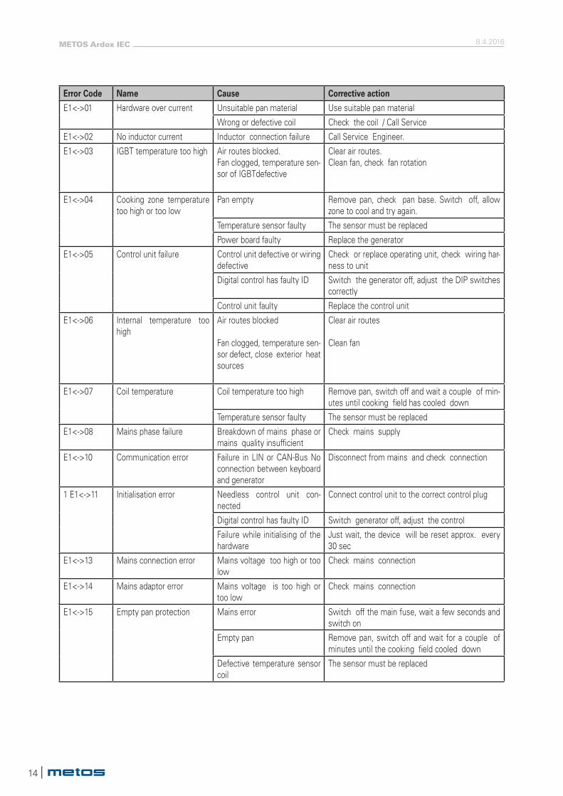
Error Code Name Cause Corrective action
E1<->01 Hardware over current Unsuitable pan material Use suitable pan material
Wrong or defective coil Check the coil / Call Service
E1<->02 No inductor current Inductor connection failure Call Service Engineer.
E1<->03 IGBT temperature too high Air routes blocked.Fan clogged, temperature sen- sor of IGBTdefective
Clear air routes.Clean fan, check fan rotation
E1<->04 Cooking zone temperature too high or too low
Pan empty Remove pan, check pan base. Switch off, allow zone to cool and try again.
Temperature sensor faulty The sensor must be replaced
Power board faulty Replace the generator
E1<->05 Control unit failure Control unit defective or wiring defective
Check or replace operating unit, check wiring har- ness to unit
Digital control has faulty ID Switch the generator off, adjust the DIP switches correctly
Control unit faulty Replace the control unit
E1<->06 Internal temperature too high
Air routes blocked
Fan clogged, temperature sen- sor defect, close exterior heat sources
Clear air routes
Clean fan
E1<->07 Coil temperature Coil temperature too high Remove pan, switch off and wait a couple of min- utes until cooking field has cooled down
Temperature sensor faulty The sensor must be replaced
E1<->08 Mains phase failure Breakdown of mains phase or mains quality insufficient
Check mains supply
E1<->10 Communication error Failure in LIN or CAN-Bus No connection between keyboard and generator
Disconnect from mains and check connection
1 E1<->11 Initialisation error Needless control unit con- nected
Connect control unit to the correct control plug
Digital control has faulty ID Switch generator off, adjust the control
Failure while initialising of the hardware
Just wait, the device will be reset approx. every 30 sec
E1<->13 Mains connection error Mains voltage too high or too low
Check mains connection
E1<->14 Mains adaptor error Mains voltage is too high or too low
Check mains connection
E1<->15 Empty pan protection Mains error Switch off the main fuse, wait a few seconds and switch on
Empty pan Remove pan, switch off and wait for a couple of minutes until the cooking field cooled down
Defective temperature sensor coil
The sensor must be replaced
| 15
8.4.2016METOS Ardox IEC
802
802
900ā30
50
250
650
50
6067
075
0
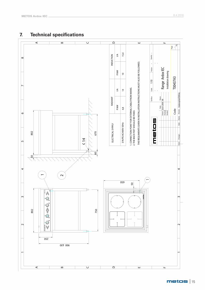
ELEC
TRIC
AL
SYPP
LY
3/N
/PE/
AC40
0V 5
0Hz
RAD
IAN
TIN
DU
CTI
ON
P/kW
I/AP/
kWI/A
4,8
1410
15,4
1. C
ON
NEC
TIO
N P
OIN
T FO
R EX
TERN
AL
CABL
E FR
OM
MA
INS.
2. T
HE
BACK
FEE
T SH
OU
LD B
E FI
XED
.
THE
REQ
UIM
ENTS
GIV
EN IN
INST
ALL
ATIO
N IN
STRU
CTI
ON
S M
UST
ALS
O B
E FO
LLO
WED
.
AR
DO
X
IEC
1
A B C D E F
87
65
43
21 1
23
4
A B C D E F
Posit
ion
Quan
tity
Pg
Page
Dat
e
Dra
wn
Nam
e
Stan
dard
Nam
eFil
enam
eCh
ange
sSt
ate
Dat
e
Chec
ked
Surf
ace
Scal
e
Code
S:\U
us lo
go II
I.jpg
U:\Induct
ion range
\Ardox4I
\T00390A
3.dwg
26.0
7.20
04VB
1:10
--
Insta
llatio
n dr
awin
g
- -- -
-
Rang
e Ar
dox I
EC
T004
37A3
¢ 14
211
2
3 4
57
8
9
10
11
121
2
3 4
56
78
9
10
11
12
6
6
5
1
2
34
6
5
1
2
34
7. Technical specifications
8.4.2016METOS Ardox IEC
16 |
1
1. C
ON
NEC
TIO
N P
OIN
T FO
R EX
TERN
AL
CABL
E FR
OM
MA
INS.
2. T
HE
BACK
FEE
T SH
OU
LD B
E FI
XED
.
THE
REQ
UIM
ENTS
GIV
EN IN
INST
ALL
ATIO
N IN
STRU
CTI
ON
S M
UST
ALS
O B
E FO
LLO
WED
.
AR
DO
X
IEC
A B C D E F
87
65
43
21 1
23
4
A B C D E F
Posit
ion
Quan
tity
Pg
Page
Dat
e
Dra
wn
Nam
e
Stan
dard
Nam
eFil
enam
eCh
ange
sSt
ate
Dat
e
Chec
ked
Surf
ace
Scal
e
Code
S:\U
us lo
go II
I.jpg
U:\Induct
ion range
\Ardox4I
\T00390A
3.dwg
1:10
--
Insta
llatio
n dr
awin
g
- -- -
-
Rang
e Ar
dox I
EC6
T046
16A3
1200
802
900ā3050
650
50
6067
0
50
21
ceran
ceran
6
5
1
2
34
6
5
1
2
34
1200
n14
1150
1
2
3 4
57
8
910
11
121
2
3 4
56
78
910
11
12
6
1
2
3 4
57
8
910
11
121
2
3 4
56
78
910
11
12
6
| 17
8.4.2016METOS Ardox IEC
-ME
TO
S-
120
119
118
117
116
115
114
113
112
111
1/2
REV
SHEE
T
Leht
i
T045
36A
3T0
4536
A3
FILE
DWG
NRPi
ir. n
ro
Typ
nro
Tied
osto
PRO
J.NR
110
108
109
107
106
105
103
102
101
104
26.1
1.20
15/A
.ODE
SING
Teki
CHKD
Hyv.
Tark
.
APPR
AR
DO
X
IEC
4H
GENE
RATO
R typ
e 78.9
9120
.104-
00
AR
DO
X
IEC
4
PE
3/N/P
E AC 4
00V,5
0-60H
z
Conn
ect E
lectri
c Pow
er
PEN
L3PE
L2L1
L3L2
L1
3/N/P
E AC 4
00V,5
0-60H
zMa
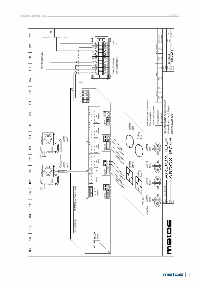
in- an
d con
trol c
ircuit
diag
ramPä
ä- ja
ohjau
svirt
apiiri
n kytk
entäk
aavio
S3 (7
8.981
00.10
0)S4
(78.9
8100
.100)
Cook
ing
Lamp
sco
nnec
tor
78.94020.002
zone
CCo
oking
Lamp
sco
nnec
tor
78.94020.002
zone
B
Chan
nel B 9 F
9 W
Chan
nel A 9 F
9 W
+PwrMgmt
gn+
+rt Co
ntro
l ALa
mps
Poti
Poti
Lamp
s
Cont
rol B
rt+
+gn
PwrMgmt+
Remo
veDo
Not
78.38900.071
78.38
900.0
60
Out1+
+Out2
+ln
Digit
al I/O
LINSe
rvice
+PwrMgmt
gn+
+rt Co
ntro
l DLa
mps
Poti
+PwrMgmt
gn+
+rt Co
ntro
l CLa
mps
Poti
L1L2
L3
Conn
ect E
lectri
c Pow
er
PE
9 W
9 F
9 W
9 F
Chan
nel C
Chan
nel D
+(vio
let)
-(gree
n)+(
violet
)-(g
reen)
3/PE A
C 400
V,50-6
0Hz
H3-(5
-28V)
H4-(5
-28V)
S3S4
Cook
ingZo
ne 1
Cook
ingZo
ne 2
Cook
ingZo
ne B
Cook
ingZo
ne C
S2S1
Ardo
x IEC
4
Zone
BCo
oking
Cook
ingZo
ne C
Zone
1Co
oking
Cook
ingZo
ne 2
ARDO
X IEC
4
Temperature sensor (re
d)
Temperature sensor (r
ed)
Coil C(blue) Coil C
(red)
Temperature sensor (re
d)
Temperature sensor (r
ed)
Coil B(blue) Coil B
(red)
2/N/P
E AC 4
00V,5
0-60H
z
3/N/
PE A
C400
V 50H
z
VERK
KO / E
LECT
RIC SU
PPLY
I/A 15,3
2x5,0
P/kW
Imax
26,1
Supp
ly cu
rrent
- and
powe
r
LIITÄ
NTÄT
IEDOT
/CON
NECT
ION
INFO
RMAT
ION
Virta-
ja te
hotie
dot
ARDO
X IE2
P/kW
I/ACi
rcuit b
reak
er3x
32A,
Type
B or
C
ARDO
X IEC
4,IEC
4HP/
kW 15,0
5,010
,9
Ardo
x C2
201
8.4.2016METOS Ardox IEC
18 |
+-
+-
APPR
Tark
.
Hyv.
CHKD
Teki
DESI
NG26
.11.
2015
/A.O
204
201
202
203
205
206
207
209
208
210
PRO
J.NR
Tied
osto
Typ
nro
Piir.
nro
DWG
NR
FILE
T045
36A
3T0
4536
A3
Leht
i
SHEE
T
REV2/
2
211
212
213
214
215
216
217
218
219
220
-ME
TO
S-
AR
DO
X
IEC
4H
AR
DO
X IE
C4
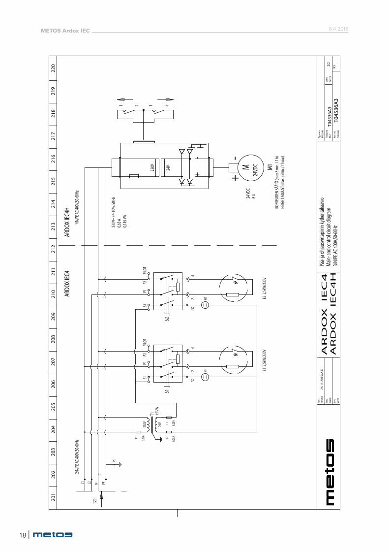
Pää-
ja oh
jausv
irtap
iirin k
ytken
täkaa
vio
Main-
and c
ontro
l circ
uit di
agram
3/N/P
E AC 4
00V,5
0-60H
z
2/N/P
E AC 4
00V,5
0-60H
zL1
S22
S2
S1P1
P2
4PILOT
15VA
T1
F3 0,25A
F2
0,25AF1
0,25A
E2 2
,5kW/
230V
H2
L2 N
24VD
C M1
PE
PE
S22
S1
S1P1
P2
4PILOT
E1 2
,5kW/
230V
H1
1/N/P
E AC 4
00V,5
0-60H
z
ARDO
X IEC
4AR
DOX I
EC4H
120
KORK
EUDE
N SÄ
ÄTÖ
(max
3 mi
n. / 1
h)HE
IGHT
ADJU
ST (m
ax. 3
min.
/ 1 ho
ur)
24 VD
C6 A
230 V
~ +/-
10%,
50 H
z0,6
3 A0,1
45 kW
M
230V 24V
1 21 2
230V 24V
| 19
8.4.2016METOS Ardox IEC
3/N/
PE A
C400
V 50H
z
VERK
KO / E
LECT
RIC SU
PPLY
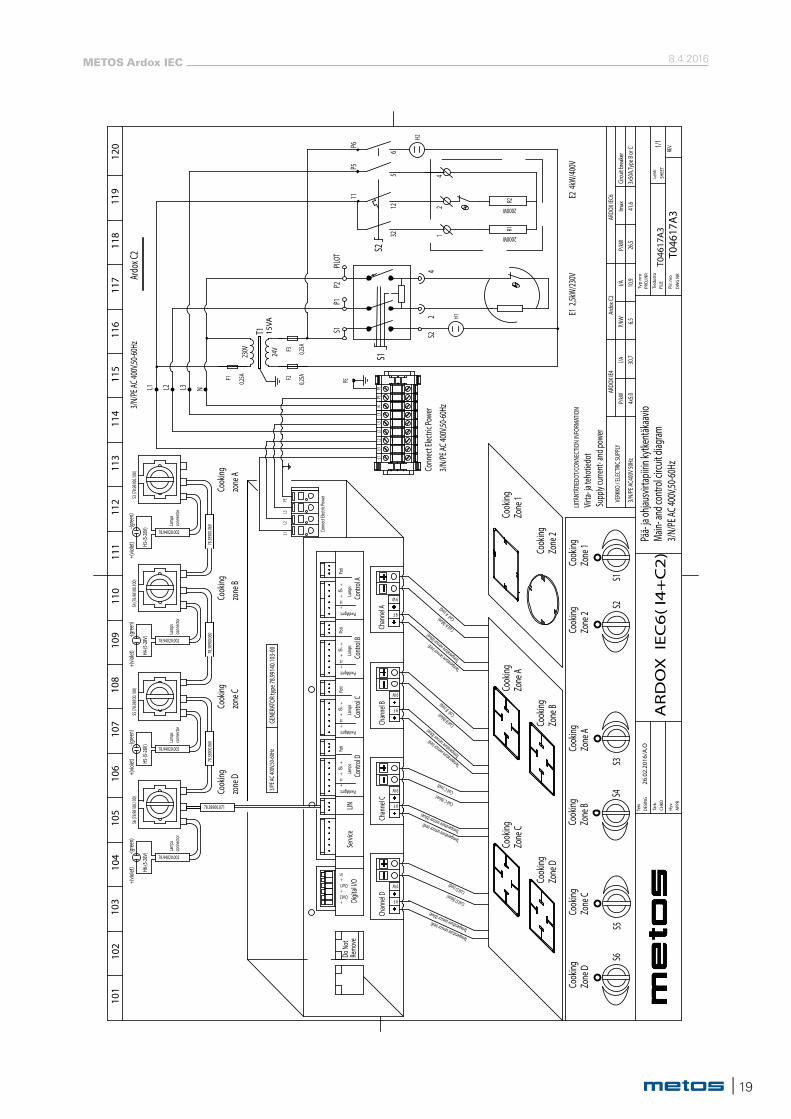
I/A 30,7
4x5,0
P/kW
Imax
41,6
ARDO
X IE4
P/kW
I/ACi
rcuit b
reak
er3x
50A,
Type
B or
C
ARDO
X IEC
6P/
kW 26,5
6,510
,9
Ardo
x C2
F3F2F1
S5 (7
8.981
00.10
0)S6
(78.9
8100
.100)
Cook
ing
Lamp
sco
nnec
tor
78.94020.002
zone
DCo
oking
Lamp
sco
nnec
tor
78.94020.002
zone
C
Chan
nel B 9 F
9 W
Chan
nel A 9 F
9 W
+PwrMgmt
gn+
+rt Co
ntro
l ALa
mps
Poti
Poti
Lamp
s
Cont
rol B
rt+
+gn
PwrMgmt+
Remo
veDo
Not
78.38900.071
78.38
900.0
60
Out1+
+Out2
+ln
Digit
al I/O
LINSe
rvice
+PwrMgmt
gn+
+rt Co
ntro
l DLa
mps
Poti
+PwrMgmt
gn+
+rt Co
ntro
l CLa
mps
Poti
L1L2
L3
Conn
ect E
lectri
c Pow
er
PE
9 W
9 F
9 W
9 F
Chan
nel C
Chan
nel D
+(vio
let)
-(gree
n)+(
violet
)-(g
reen)
H5-(5
-28V)
H6-(5
-28V)
S6
Cook
ingZo
ne A
Cook
ingZo
ne B
Cook
ingZo
ne C
Cook
ingZo
ne D
S4S3
Zone
CCo
oking
Cook
ingZo
ne D
Zone
1Co
oking
Cook
ingZo
ne 2
PEN
PEL2
L1L3
L2L1
Ardo
x C2
3/PE A
C 400
V,50-6
0Hz
S4 (7
8.981
00.10
0)
Cook
ing
Lamp
sco
nnec
tor
78.94020.002
zone
B
78.38
900.0
60
+(vio
let)
-(gree
n)
H4-(5
-28V)
Cook
ing
Lamp
sco
nnec
tor
78.94020.002
zone
A
78.38
900.0
60
+(vio
let)
-(gree
n)
H3-(5
-28V)
Zone
ACo
oking
Cook
ingZo
ne B
S1S2
Cook
ingZo
ne 1
Cook
ingZo
ne 2
S5
R1
2000W
2000W
R2
S2
H2
11P5
P6
65
1232 1
24
L3
S3 (7
8.981
00.10
0)3/N
/PE A
C 400
V,50-6
0Hz
Temperature sensor (red)Temperature sensor (blue)
Coil D (blue)Coil D (red)
Temperature sensor (red)Temperature sensor (blue)
Coil C (blue)Coil C (red)
Temperature sensor (red)
Temperature sensor (blue)
Coil B (blue) Coil B (re
d)
Temperature sensor (red)
Temperature sensor (blue)
Coil A (blue) Coil A (re
d)
Supp
ly cu
rrent
- and
powe
r
LIITÄ
NTÄT
IEDOT
/CON
NECT
ION
INFO
RMAT
ION
Virta-
ja te
hotie
dot
-ME
TO
S-
120
119
118
117
116
115
114
113
112
111
1/1
REV
SHEE
T
Leht
i
T046
17A
3 T0
4617
A3
FILE
3/N/P
E AC 4
00V,5
0-60H
zMa
in- an
d con
trol c
ircuit
diag
ramPä
ä- ja
ohjau
svirt
apiiri
n kytk
entäk
aavio
DWG
NRPi
ir. n
ro
Typ
nro
Tied
osto
PRO
J.NR
110
108
109
107
106
105
103
102
101
104
26.0
2.20
16/A
.ODE
SING
Teki
CHKD
Hyv.
Tark
.
APPR
AR
DO
X I
EC
6(
I4+
C2
)
GENE
RATO
R typ
e 78.9
9140
.103-
00
L1
15VA
T1
230V 24V 0,25A
0,25A
0,25A
E2 4
kW/40
0V
L2 N
PE
3/N/P
E AC 4
00V,5
0-60H
z
Conn
ect E
lectri
c Pow
erS2
2
S1
S1P1
P2
4PILOT
H1 E1 2
,5kW/
230V
L3
8.4.2016METOS Ardox IEC
20 |
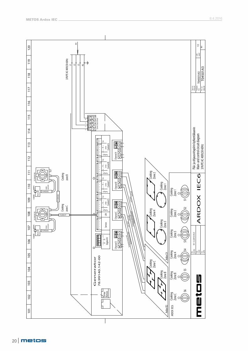
Ge
ne
ra
to
r
78
.99
14
0.1
42
-00
AR
DO
X
IEC
6AP
PR
Tark
.
Hyv.
CHKD
Teki
DESI
NG01
.12.
2015
/A.O
104
101
102
103
105
106
107
109
108
110
PRO
J.NR
Tied
osto
Typ
nro
Piir.
nro
DWG
NR
FILE
T045
01A
3T0
4501
A3
Leht
i
SHEE
T
REV1/
2
111
112
113
114
115
116
117
118
119
120
-ME
TO
S-
Chan
nel D
Chan
nel C
9 F
9 W
9 F
9 W
Pää-
ja oh
jausv
irtap
iirin k
ytken
täkaa
vio
Main-
and c
ontro
l circ
uit di
agram
3/N/P
E AC 4
00V,5
0-60H
z
Poti
Lamp
s
Cont
rol C
rt+
+gn
PwrMgmt+
Poti
Lamp
s
Cont
rol D
rt+
+gn
PwrMgmt+
Servi
ceLIN
Digit
al I/O
ln+
Out2+
+Out1
78.38
900.0
60
78.38900.071
Do N
ot
Remo
ve
ARDO
X IEC
6
Cook
ing
Cook
ing
Cook
ing
Cook
ing
Ardo
x IE2
+PwrMgmt
gn+
+rt Co
ntro
l BLa
mps
Poti
Poti
Lamp
s
Cont
rol A
rt+
+gn
PwrMgmt+
9 W
9 F
Chan
nel A
9 W
9 F
Chan
nel B
zone
B
H5-(5
-28V) 78.94020.002
conn
ecto
rLa
mps
Cook
ing
zone
C
H6-(5
-28V) 78.94020.002
conn
ecto
rLa
mps
Cook
ing
Temp
eratur
e sen
sor (r
ed)
Coil C
(blue
)
S6 (7
8.981
00.10
0)S5
(78.9
8100
.100)
202
PE
Conn
ect E
lectri
c Pow
er
L3L2
L1
+(vio
let)
-(gree
n)-(g
reen)
+(vio
let)
S1S2
S5S6
Cook
ingZo
ne C
Zone
BCo
oking
Zone
4Co
oking
Zone
3Co
oking
Zone
2Co
oking
Zone
1Co
oking
Temp
eratur
e sen
sor (b
lue)
Coil C
(red)
Coil B
(red)
Coil B
(blue
)
Temp
eratur
e sen
sor (r
ed)
Temp
eratur
e sen
sor (b
lue)
Cook
ing
Cook
ing
Ardo
x C4
S4S3
PEL3L2L13/N
/PE A
C 400
V,50-6
0Hz
Zone
3
Zone
4Zo
ne C
Zone
B
Zone
2
Zone
1
| 21
8.4.2016METOS Ardox IEC
230V 24V
AR
DO
X
IEC
6AP
PR
Tark
.
Hyv.
CHKD
Teki
DESI
NG01
.12.
2015
/A.O
204
201
202
203
205
206
207
209
208
210
PRO
J.NR
Tied
osto
Typ
nro
Piir.
nro
DWG
NR
FILE
T045
01A
3T0
4501
A3
Leht
i
SHEE
T
REV2/
2
211
212
213
214
215
216
217
218
219
220
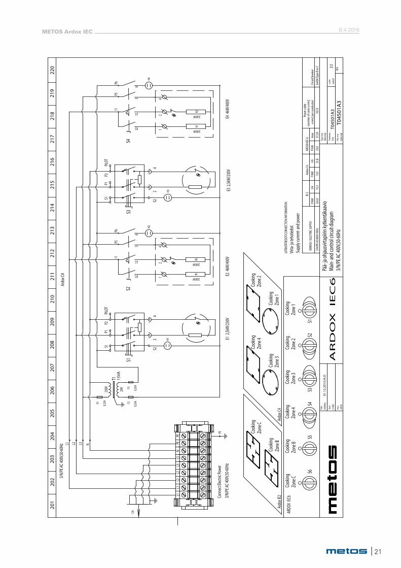
-ME
TO
S-
Pää-
ja oh
jausv
irtap
iirin k
ytken
täkaa
vio
Main-
and c
ontro
l circ
uit di
agram
3/N/P
E AC 4
00V,5
0-60H
z
Supp
ly cu
rrent
- and
powe
r
LIITÄ
NTÄT
IEDOT
/CON
NECT
ION
INFO
RMAT
ION
Virta-
ja te
hotie
dot
2000W
2000W
E4 4
kW/40
0V
R1R2
PE
3/N/P
E AC 4
00V,5
0-60H
z L1
H4
S4
11
Ardo
x C4 R1
2000W
2000W
R2
S22
S1
S1P1
P2
4PILOT
120
S3S4
Ardo
x C4
Zone
3Co
oking
Cook
ingZo
ne 4
Cook
ingZo
ne 1
Cook
ingZo
ne 2
Cook
ingZo
ne 3
Cook
ingZo
ne 4
Cook
ingCo
oking
S6S5
S2S1
Ardo
x IE2
Cook
ing
Cook
ing
Zone
2Co
oking
Cook
ingZo
ne 1
ARDO
X IEC
6
15VA
T1
F3 0,25A
F2
0,25AF1
0,25A
PILOT
4
P2P1
S1
S3
2S2
E1 2
,5kW/
230V
E2
4kW
/400V
E3 2
,5kW/
230V
H1H3
S2
H2
P5P6
125
632
11P5
P6
65
1232
21
41
24
L2 L3 N
3/N/P
E AC 4
00V,5
0-60H
z
Conn
ect E
lectri
c Pow
er
PEN
L3PE
L2L1
L3L2
L1
Zone
CZo
ne B
Zone
C
Zone
B
3/N/
PE A
C400
V 50H
z
VERK
KO / E
LECT
RIC SU
PPLY
I/A 15,3
2x5,0
P/kW
Imax
37,2A
IE 2
P/kW
I/ACi
rcuit b
reak
er3x
40A,
Type
B or
C
ARDO
X IEC
6
23,0
13,0
21,8
Ardo
x C4
P/kW
Powe
r cab
le
5G10
(num
ber o
f cor
es x
mm
2 x m
m2 p
er co
nduc
tor)
8.4.2016METOS Ardox IEC
22 |
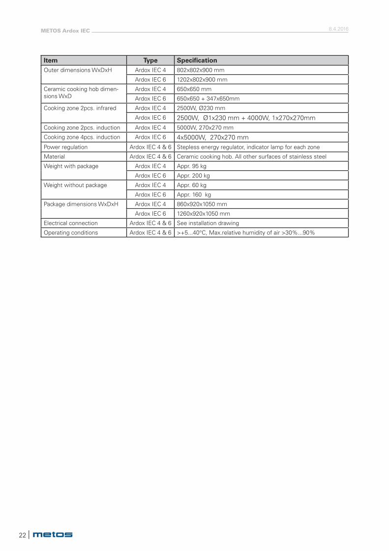
Item Type SpecificationOuter dimensions WxDxH Ardox IEC 4 802x802x900 mm
Ardox IEC 6 1202x802x900 mm
Ceramic cooking hob dimen-sions WxD
Ardox IEC 4 650x650 mm
Ardox IEC 6 650x650 + 347x650mm
Cooking zone 2pcs. infrared Ardox IEC 4 2500W, Ø230 mm
Ardox IEC 6 2500W, Ø1x230 mm + 4000W, 1x270x270mmCooking zone 2pcs. induction Ardox IEC 4 5000W, 270x270 mm
Cooking zone 4pcs. induction Ardox IEC 6 4x5000W, 270x270 mmPower regulation Ardox IEC 4 & 6 Stepless energy regulator, indicator lamp for each zone
Material Ardox IEC 4 & 6 Ceramic cooking hob. All other surfaces of stainless steel
Weight with package Ardox IEC 4 Appr. 95 kg
Ardox IEC 6 Appr. 200 kg
Weight without package Ardox IEC 4 Appr. 60 kg
Ardox IEC 6 Appr. 160 kg
Package dimensions WxDxH Ardox IEC 4 860x920x1050 mm
Ardox IEC 6 1260x920x1050 mm
Electrical connection Ardox IEC 4 & 6 See installation drawing
Operating conditions Ardox IEC 4 & 6 >+5...40°C, Max.relative humidity of air >30%...90%


![SCIENTIFIC REPORT: A MULTIFACTORIAL … · products [Ardox-X™ and Corsodyl oral rinses], each tested against a water ... above specified age ranges, and if they had any serious](https://img.pdfslide.us/doc/110x75/5b33abe27f8b9abc218b4c78/scientific-report-a-multifactorial-products-ardox-x-and-corsodyl-oral-rinses.jpg)