Embed Size (px)
Citation preview

1
Methods for ValidatingCockpit Design
The best tool for the task
_________________________
2
Gideon Singer
Methods for ValidatingCockpit Design
The best tool for the task
Department of AeronauticsKungliga Tekniska Högskolan (KTH)
Royal Institute of TechnologySE-100 44 Stockholm
SwedenMarch, 2002
Report 2002-6ISSN 0280-4646

3
Acknowledgements
The idea for this thesis started at 33 000 ft over the Canadian wilderness onboard a SAS flightsitting next to Lena Mårtensson. Lena was the one driving me to choose the path into the field ofHuman Factors. Without her enthusiasm and support I would never have taken this upon myself.
Professor Lena Mårtensson and Professor Arthur Rizzi have been enthusiastic and very helpfultutors especially in keeping me on track and helping me structure and illustrate my thesis so as tomake it clear and logical. Lena has been energetic in making our research results known inSweden and in Europe by keeping a constant contact with research institutes, journals, airlinesand the general public.
Doctor Sidney Dekker has been my main support in the technical papers included in this thesis.He has been an active partner in the brainstorming of ideas, developing experiment designs, andanalyzing the statistical relevance of the results. From his parts of the papers, I have also had theprivilege of learning new ways of using the English language.
As a senior test pilot at SAAB and Fairchild Dornier, I have been involved in the design andevaluation of the interface between the crew and cockpit controls and displays during thedifferent development and approval phases. During these years I have had the pleasure ofworking in test teams with many talented and dedicated test engineers and designers that withouttheir contribution these aircraft would not have had such a good safety record. I would like tothank especially Ulf Persson and Nigel Pippard for teaching me how to fight for a better designeven when risking being unpopular for a while. I would also like to thank Martin Angerer, whowith his many design ideas has been a great source of inspiration. Special thanks to HazelCourteney for listening to my ideas and discussing them with great enthusiasm and for taking thetime to review my work. I’m particularly grateful to Douglas Picha who thoroughly read thethesis and helped me debug the last draft.
SAAB has always been committed to aerospace research and has invested time and resources inHuman Factors. My gratitude to SAAB (and SAAB Aircraft in particular) for partially fundingmy research activities as part of the National Aeronautical Research Program (NFFP) and theCHECKPOINT project and to the EU for the generous funding of the DIVA and CHECKPOINTprojects.
My greatest love to my family - my wife Anna, who showed me that it is possible to write athesis and my children Mira and Adam for understanding me when I was all preoccupied withother thoughts. Finally, I would like to thank my father, Professor Josef Singer, for taking thetime to make a thorough and constructive review of several of the drafts even when he himselfwas busy with his own book.
Munich, February 12th, 2002
Gideon Singer
Summary
4
Summary
This thesis addresses the process of cockpit-design validation and certification in transportcategory commercial aircraft. The thesis covers several fundamental issues of the process as it istoday, and proposes a modified approach based on flight test experience and empirical results.
The thesis is based on four original published papers appended: Paper A discusses measured pilotperformance during multiple. Paper B analyses An example of the certification process ofmodern avionics. Paper C questions the role of the Test Pilot in the validation process anddescribes the new Human Factors certification process initiative. Finally, Paper D shows a casestudy measuring pilot performance when using a basic flight instrument.
Papers B and C discuss the present process of validation and approval by using industryexperience, focusing on specific examples from actual projects. Using the deficiencies foundthey propose new methods of approval. Papers A and D provide empirical proof of such newmethods by measuring pilot performance when operating several design solutions using apractical simulation tool. The main aim of showing these empirical results is to highlight thedeficiencies of the present validation methods and propose a structured method of usingevaluation tools.
This thesis proposes a new process for cockpit design validation aimed at commercial aircraftprojects. The process combines a new role for the test pilot, the structured use of part-tasksimulation in combination with the introduction of detailed requirements and application ofobjective criteria. Comparing existing designs with ones derived by the new proposed methodsand comparing empirical simulation results demonstrate the advantages of using this process.
The main goal of the new process is to enable the identification of design problems earlier in thedesign phase. This is done by early use of simple simulation tools, widening the evaluation loopsand including the end user early in the process. Implementing such an approach will minimizethe need for corrective measures such as training, procedures and limitations. Minimizing theerror risk of critical functions in highly automated systems will move us closer to our ever higherflight safety goals.
Note:The terms Test Pilot and Pilot will be referred to in the masculine form for simplicity and do notexclude female pilots.

Summary
5
Dissertation
This thesis is based on several original papers published by the author alone or together with aco-author. The thesis will guide the reader through the background, research proposal, methods,discussion and conclusions that correlate the individual papers and show the rationale for the newstructured process of cockpit-design validation.
The following papers are appended and are an integral part of this thesis The papers are presentedin the order of their publication dates (Papers A-D):
Paper ASinger, G. & Dekker, S., (2000). Pilot performance during multiple failures: AnEmpirical study of different warning systems , Transportation Human Factors 2(1), pp.63-76. Lawrence Erlbaum Associates, Inc.
Paper BSinger, G. & Dekker, S., (2001). The ergonomics of flight management systems: Fixingholes in the cockpit certification net. Applied Ergonomics 32, pp. 247-254. Aldershot, UK:Elsevier Science Ltd.
Paper CSinger, G., (2001). Minimizing pilot-error by design: Are test pilots doing a goodenough job? Human Factors and Aerospace Safety, vol. 1, (nr. 4), pp. 301-321, UK:Ashgate Publishing.
Paper DSinger, G. & Dekker, S., (2002). The effect of the roll index (sky pointer) on roll reversalerrors. Human Factors and Aerospace Safety, vol. 2 (nr. 1), pp. 33-43, UK: AshgatePublishing.

Summary
6
Historical summary of performed work included in this thesis
My aviation background started 1975 as a military pilot in the Israeli Air force. 1989, completingmy M.Sc. in Aeronautics at the Royal Institute of Technology (KTH) in Stockholm, I wasemployed by Saab Aircraft and trained as an experimental test pilot. During my years as test pilotat Saab Aircraft and Fairchild-Dornier I have participated in several development andcertification projects of large commercial aircraft. Between 1996 and 2000 I was involved in aSwedish National Aeronautical Research (NFFP) initiative addressing warning systems incommercial aircraft (Mårtensson & Singer 1998). The research involved the Swedish aircraftindustry (Saab Aircraft AB) and an academic institute (KTH). Involvement as the projectmanager and as a test pilot and working with Lena Mårtensson and other researchers in the fieldprovided me with a unique insight into the field of Human Factors. The project highlighted theproblems encountered in a modern cockpit (advanced warning systems) and provided subjectiveinterview results from a wide variety of pilots. The results were in some cases conflicting and thevalidity of pilot opinion was questioned in several issues. In order to check these suspicions, anempirical study was proposed to measure pilot response times and error rates when using thedisplay methods addressed in the interview phase. This experiment was my first empirical workin the field and is described in Paper A.
Becoming fascinated by the field of Human Factors, and yet interested in the application inaviation, I applied as an industry participant 1997 for the doctorate program at the Department ofAeronautics of the Royal Institute of Technology (KTH) in Stockholm, Sweden. However, due tomy main area of interest being Human Factors, much of the tutoring and cooperation with otherdoctorate students took place in the Human Machine Systems group at KTH. I also joined theHuman Factors in Aviation (HFA) doctorate program at the Linköping University of Technology(LiTH) where the theory and tools for Paper A were acquired and the excellent help in theory andanalysis was given by Sidney Dekker.
During my work 1997-2000 as a Design Reviewer (DER) representative for the Swedish CivilCertification Authorities (CAA/LFV) at Saab Aircraft, I encountered many Human Factors issuesregarding the approval of cockpit interface. Paper B was written based on issues discoveredduring several approval phases of Flight Management System (FMS) installations on the SAAB340 and the SAAB 2000.
In 1999 I became a member of the FAA/JAA Human Factor Harmonization Working Group(HF-HWG). Working in this group exposed me to the full range of problems identified in thepresent certification process of modern cockpits. Together with more than 40 specialists in thefield, I was involved in the long process of the detailed analysis, consolidation andrecommendation phases of producing new regulatory material. This work, described in Paper C,has helped in combining my previous experience in industry with the experimental workperformed as part of this thesis.
In order to summarize my experience in aircraft flight test and certification between 1989 and2001 and structure the dilemma of test pilots and the way they are involved in the approvalprocess, Paper C was written as a position paper. The aim of this paper was to highlight thepresent process deficiencies, show specific examples and propose the modification of the testpilot role in the future.

Summary
7
In early 2000, following the loss of an aircraft without any clear indication as to the cause, theissue of primary attitude displays was brought into light. During my years as test pilot I have inseveral cases seen tendencies for wrong recovery from a static banked turn. In order toinvestigate the issue and implement my thesis tools and process, Paper D was written usingempirical data showing pilot errors and using the end user population.
At the end of 2000, I began working as a test pilot for Fairchild-Dornier on a new TransportCategory aircraft project (Do728) that incorporated many novel interface features. New HumanFactors issues were identified and based on empirical results and using simple tools the proposedmethodology was partially implemented in the design process. This work is described in thethesis and used as partial proof of the new proposed process.
I have had the privilege of being able to implement some of my research results and proposals inan actual project already in the design phases. In the coming years, the certification andoperational experience will tell whether the new process and method produced a safer andoperationally more usable cockpit interface.
Summary
8
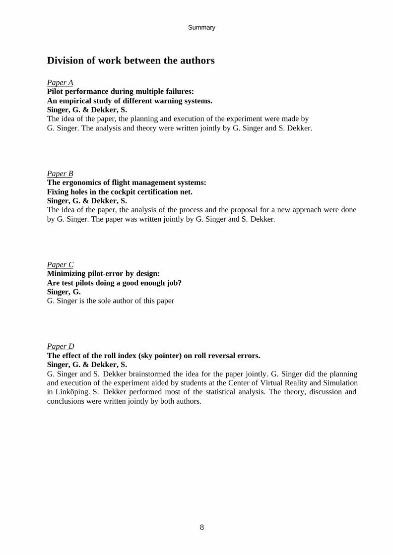
Division of work between the authors
Paper APilot performance during multiple failures:An empirical study of different warning systems.Singer, G. & Dekker, S.The idea of the paper, the planning and execution of the experiment were made byG. Singer. The analysis and theory were written jointly by G. Singer and S. Dekker.
Paper BThe ergonomics of flight management systems:Fixing holes in the cockpit certification net.Singer, G. & Dekker, S.The idea of the paper, the analysis of the process and the proposal for a new approach were doneby G. Singer. The paper was written jointly by G. Singer and S. Dekker.
Paper CMinimizing pilot-error by design:Are test pilots doing a good enough job?Singer, G.G. Singer is the sole author of this paper
Paper DThe effect of the roll index (sky pointer) on roll reversal errors.Singer, G. & Dekker, S.G. Singer and S. Dekker brainstormed the idea for the paper jointly. G. Singer did the planningand execution of the experiment aided by students at the Center of Virtual Reality and Simulationin Linköping. S. Dekker performed most of the statistical analysis. The theory, discussion andconclusions were written jointly by both authors.

Summary
9
Summary of appended papers
Paper A:Pilot performance during multiple failures: An empirical study of different warningsystems.
Aircraft warning system philosophy was chosen as a case study to demonstrate the evaluationof a complex and highly automated feature in a modern commercial cockpit. The hypothesiswas that despite interview based pilot preference for detailed information, objectiveperformance is superior when presented with highly processed data. Empirical performancedata was collected using a part-task simulator exposing a variety of pilots to typical multiplefailure scenarios in a high workload environment. Four different methods of sorting andprioritization of warning information representing four existing aircraft systems in use weretested. Response times and error rates were measured and analyzed. Statistically significantresults showed preference to highly automated and processed information. This paper showsthe effective use of part-task simulation to achieve objectively validated data in order todetermine the best of several design solutions.
Paper B:The ergonomics of flight management systems: Fixing holes in the cockpit certificationnet.
Based on a review of several cases of new installations approved in modern aircraft, theFlight Management System (FMS) interface features are discussed in detail. The efficiency ofthe certification process in general and the present requirements in particular are questioned.The underlying difficulties in the new skills and knowledge required of the system operatorare discussed. Several proposals for new requirements are made and the implementation of anobjective simulation validation process is described. The proposed certification methodminimizes subjective bias and exposes the end user pilot to an operational scenario withPass/Fail criteria. This paper highlights the certification process deficiencies when addressingcomplex systems and shows several incremental improvements.
Paper C:Minimizing pilot-error by design: Are test pilots doing a good enough job?
Test pilots have always been central figures in the validation and certification process ofcockpit interface design. Based on incident and accident reports and other deficienciesencountered by the author in his work, the role of the test pilot in this process is questioned.The tools available to the test pilot and methods of using them are described and evaluated. Inthis position paper, a new role for the test pilot is proposed, emphasizing the planning andanalysis tasks of the test pilot rather than the present role as a participating subject pilot.Furthermore, this paper describes the work done by the HF-HWG in finding the deficienciesin the present set of Human Factors, design related, certification requirements and advisorymaterial.

Summary
10
Paper D:The effect of the roll index (sky pointer) on roll reversal errors.
The basic Attitude Display Indicator (ADI) is used in a case study showing seriousdeficiencies in display design features accepted by tradition rather than by objective testing.Using simple part-task simulation, a variety of pilots are asked to recover from differentconditions of normal banked flight. Three types of ADI conventions are used and error ratesand response times recorded. Statistically significant results show nearly five times highererror rates when using the ADI common in commercial aircraft compared with the ones usedon military or general aviation aircraft. This paper, in addition to highlighting a seriousdeficiency in an existing feature, shows a simple method of attaining empirical data for use inthe new design process.

Contents
11
ContentsACKNOWLEDGEMENTS ...................................................................................................................................................3
SUMMARY................................................................................................................................................................................4
DISSERTATION......................................................................................................................................................................5
HISTORICAL SUMMARY OF PERFORMED WORK INCLUDED IN THIS THESIS .................................6
DIVISION OF WORK BETWEEN THE AUTHORS ..................................................................................................8
SUMMARY OF APPENDED PAPERS.............................................................................................................................9
ABBREVIATIONS AND ACRONYMS ......................................................................................................................... 14
1 BACKGROUND......................................................................................................................................................... 16
2 PROBLEM DEFINITION....................................................................................................................................... 17
2.1 Modern cockpit complexity................................................................................................172.2 Innovation or commonality................................................................................................172.3 Selling gimmicks................................................................................................................172.4 New systems mandated for old aircraft ..............................................................................172.5 Extensive use of multi modal interface..............................................................................182.6 Evaluating Novel features ..................................................................................................192.7 Cockpit evaluation process – feedback loops.....................................................................212.8 “Band-Aid” fixes ................................................................................................................222.9 Training to cover for design flaws......................................................................................222.10 Inadequacies of the evaluation methods presently used by industry..............................22
2.10.1 Cockpit ergonomics....................................................................................................222.10.2 Avionics systems integration......................................................................................232.10.3 Flight testing...............................................................................................................242.10.4 Certification criteria....................................................................................................242.10.5 Certification flights.....................................................................................................25
2.11 Summary.........................................................................................................................26
3 THE RESEARCH PROPOSAL OF THE THESIS .......................................................................................... 27
3.1 Aim of the thesis.................................................................................................................273.2 The scope............................................................................................................................273.3 Methodology.......................................................................................................................27
4 HUMAN FACTORS THEORIES AND METHODS IN AVIATION ......................................................... 28
4.1 The paradox of information display...................................................................................284.2 Warnings and risk communication.....................................................................................294.3 Addressing human error.....................................................................................................304.4 Human performance using warning systems......................................................................304.5 Validating simulators for Human Factors use....................................................................314.6 Evaluating integrated information systems ........................................................................324.7 Decision aids for the complex cockpit ...............................................................................324.8 User involvement................................................................................................................334.9 Implementation by industry................................................................................................34
5 DEFICIENCIES ADDRESSED IN THIS THESIS .......................................................................................... 35
Contents
12
5.1 Attitude Indicator conventions ...........................................................................................355.2 What information does the pilot need?...............................................................................385.3 Text message syntax...........................................................................................................395.4 The assumptions regarding crew error...............................................................................405.5 Integration of FMS.............................................................................................................41
6 RESEARCH METHODS OF THE THESIS ...................................................................................................... 44
6.1 Static presentation as a tool for convincing management ..................................................446.2 PC slide-show for comparing display features...................................................................456.3 PC static simulation for measuring pilot response .............................................................466.4 Part-task simulation for evaluating pilot performance in high workload scenarios...........47
7 RESULTS ..................................................................................................................................................................... 49
7.1 Capitals or Mixed font – Recall ability..............................................................................497.2 Error rates when reading text .............................................................................................497.3 Recovery errors from a banked flight condition.................................................................507.4 Pilot performance during multiple system failures ............................................................527.5 Measuring end-to-end performance and workload.............................................................537.6 The DIVA project...............................................................................................................537.7 New Human Factors rules and guidance material..............................................................54
8 NEW PROCESS METHODOLOGY.................................................................................................................... 57
8.1 The new validation process - an overview.........................................................................578.2 Using part-task simulation tools for early, fact based, design decisions ............................598.3 Full simulation for validating crew performance and workload ........................................598.4 Quantifying human error risk .............................................................................................628.5 Modifying the role of the test pilot.....................................................................................64
9 DISCUSSIO N.............................................................................................................................................................. 66
9.1 The best tool for the task ....................................................................................................669.2 The need for statistical significance...................................................................................679.3 The way ahead with Human Factors certification requirements ........................................679.4 Objective criteria for measuring human performance........................................................689.5 Giving human error probability numbers...........................................................................699.6 Line pilots as the final evaluators.......................................................................................70
10 CONCLUSIONS ......................................................................................................................................................... 72
10.1 Widening the feedback loops and evaluator groups.......................................................7210.2 Early use of part-task simulation....................................................................................7210.3 Developing detailed certification material.....................................................................7310.4 Modifying the task of test pilots.....................................................................................73
REFERENCES ...................................................................................................................................................................... 74
Appendices:Paper A Pilot performance during multiple failures: An empirical study of different
warning systems.Paper B The ergonomics of flight management systems: Fixing holes in the cockpit
certification net.Paper C Minimizing pilot-error by design: Are test pilots doing a good enough job?Paper D The effect of the roll index (sky pointer) on roll reversal errors.
Contents
13
List of FiguresFigure 1: FMS retrofit into a Saab 340 cockpit – notice installation on aft central panel..............18Figure 2: A typical layout of modern cockpit controls (Do728)....................................................20Figure 3: Novel cockpit controls – Cursor Control Device (CCD) ...............................................20Figure 4: The present schematic review process of cockpit design...............................................21Figure 5 Typical electronic displays with multiple features.........................................................28Figure 6: The two reference methods for using an Attitude Indicator...........................................36Figure 7: The Sky and Earth roll pointers (do not appear together)..............................................36Figure 8: The three methods of displaying roll index on an ADI..................................................37Figure 9: A typical display following a severe electrical failure ...................................................39Figure 10: Two examples of the use of function keys on FMS CDUs ........................................42Figure 11: Two methods to display text (upper and mixed case) ................................................44Figure 12: Three methods of structuring text messages – using a slide show program...............46Figure 13: Mixed font showed superior content recall.................................................................49Figure 14: Roll recovery error rates when using three types of ADI...........................................51Figure 15: RT and error-rates identifying primary cause using four display philosophies .........52Figure 16: New proposed design validation loops and tools (e, f, g & h) ...................................58Figure 17: A partial simplified workload assessment tool for line pilot participation................61Figure 18: The basis for system failure analysis in FAR/JAR AC(J) 25.1309............................62

Contents
14
Abbreviations and AcronymsAC Advisory CircularACJ Advisory Circular JointADI Attitude Display IndicatorAFM Airplane Flight ManualAP Auto PilotARAC Aviation Rulemaking Advisory CommitteeATC Air Traffic ControlAWO All Weather OperationsCAA Civil Aviation Administration (UK)CAS Crew Alerting SystemCCD Cursor Control DeviceC-HIP Communication-Human Information ProcessingCDU Control Display Unit (used mainly for FMS)CFIT Controlled Flight Into TerrainCFR 14 Civil Federal Regulations in USACRT Cathode Ray TubeDIVA Design of Human/Machine and their validation in AeronauticsD-RT Detection or Reaction TimeEADI Electronic Attitude Display IndicatorECL Electronic Check ListEFIS Electronic Flight InstrumentsEHA Error Hazard AnalysisEVS Enhanced Vision SystemsFAA Federal Aviation AdministrationFD Flight DirectorFHA Functional Hazard AnalysisFMS Flight Management SystemFPLN Flight PlanFOCA Federal Office of Civil Aviation - SwitzerlandFSF Flight Safety FoundationHF-HWG Human Factors Harmonization Working GroupHGS Head-up flight Guidance SystemHUD Head-Up DisplayICIS Integrated Crew Information SystemILS Instrument Landing SystemISO International Standard OrganizationJAA Joint Aviation Administration (Europe)JAR-OPS Joint Aviation Requirements - OperationsLCD Liquid Crystal DisplayLNAV Lateral NavigationMBR Model Based Reasoning

Contents
15
MOS Mission Oriented SimulatorsNASA National Aeronautics and Space AdministrationNAV NavigationNDB Non Directional Beacon (Navigation aid)ND Navigation DisplayNPA Notice Proposed AmendmentPFD Primary Flight DisplayPSM+ICR Propulsion System Malfunction plus Inappropriate Crew
ResponseQFD Quality Function DeploymentRNAV Area NavigationSAE Society of Automotive EngineeringSART Situational Awareness Rating TechniqueSETP Society of Experimental Test PilotsSME Subject Matter ExpertsSSA System Safety AssessmentTAWS Terrain Awareness and Warning SystemTLX Task Load ratingsVAPS Virtual Applications Prototyping SystemVHF Very High Frequency - radiosVspeed Safety speeds for takeoff (V1, Vr, V2…)VNAV Vertical Navigation
Background
16
1 Background
It has been well documented that at least 70% of commercial aircraft accidents in the last 15years were human error related (FAA, 1996). The global nature of the problem is emphasized inthe newly UK CAA released policy paper referring to several independent studies with similarconclusions (CAA, 2000). A specific international investigation to determine causes of accidentsdue to Propulsion System Malfunction plus Inappropriate Crew Response (PSM+ICR) wasconducted in the late 90’s by airframe manufacturers (AIA/AECMA, 1998). The investigationdiscovered several similar Human Factors deficiencies.
The cockpit of an airliner is designed for the specific task of providing a safe and efficientinterface with the operators, nowadays, often two pilots. Despite the similar tasks performed byall crews, designs vary greatly between manufacturers and hardly any standards exist for theinterface methods.
The present methods of validating cockpit designs rely mostly on subjective statements andevaluations of a limited number of test pilots. This results in design solutions that have beenapproved for use without a realistic operational test and without objective or global agreed uponminimum acceptable performance levels. Unlike the technical system approval process thatfollows strict international standards and testing criteria, the Human Factors interface evaluationlacks such standards.
The evaluation and approval process today comprises several review phases with the appropriatefeedback for change. The timing of the feedback is directly related to the effort and cost of eachchange. This constraint causes many manufacturers to defer design changes and instead apply“Band-Aid” fixes in the form of procedures, limitations and special training to overcome designweaknesses identified at the final stages of approval.
Design decisions regarding cockpit interface have always been made based on subjectivestatements of test pilots. Test pilots rely on the certification regulations, company designphilosophy and own previous experience (Singer, 1992; Singer & Persson, 1996). The design isscrutinized in reviews, flight tests and certification tests and is formally approved before it isallowed to enter service. And yet, most accidents lately have occurred despite this process. Basedon this rationale it could be claimed that the test pilots have not been doing a good enough job.Blaming the test pilots for design deficiencies in cockpit interface would be unfair withouthighlighting the present process, its methods and tools. The result of an evaluation of a design isonly as good as the tools used and the methods applied.
Several of these issues, showing the limitations of the present process, have been discussed in theauthor’s previous research (Singer, 2000). The author shows the present process of flight-testingas a tool for validating different design features and cockpit interface. The weaknesses in thatmethod are highlighted and a qualitative approach is used for showing successful and deficientexamples of the present methodology of flight test. It concludes by pointing out that two majorareas of concern exist in the present process of validating cockpit design through flight test:• Inadequate certification material is partly the reason of deficient solutions and makes the
development and certification test work less predictable for the flight test teams.• Lack of an acceptable validation method for pilot performance when using a newly installed
system may result in immature interface features.

Problem definition
17
2 Problem definition
2.1 Modern cockpit complexityThe cockpit of a modern commercial airliner today incorporates many highly automated systems.The way the systems are integrated with cockpit controls and displays varies with vendors andaircraft manufacturers. The high authority and autonomy of some of these systems raise newissues of crew awareness, perception and communication with such systems in both normal andabnormal situations (Wickens, 1992; Billing, 1997). The difficulties start already during thedesign and evaluation phases of such an interface. In many cases, system definition is finalizedquite late in the design process and the full functionality is not visible to the evaluator until thefinal phase of testing. At that stage deficiencies are therefore often accepted without necessarilyaddressing the Human Factors design issues. The result is often that the full implication to thetotal design philosophy is not always addressed due to cost and schedule constraints.
The following sections will highlight several of the driving factors in the design and approvalprocess that contribute to Human Factors related design deficiencies:
2.2 Innovation or commonalityA clear trend in the last decade has been to market aircraft families rather than individual models.This allows the airline to be more flexible, determining the size of aircraft put daily into servicethus assuring minimum retraining of crews and other personnel. Unfortunately, designcommonality resulted in some cases retaining bad design features even in newer aircraft models(B737 NG, MD90). The operational requirements of having similar cockpit design and controlshave left a design of the 90s with technical features from the 60s. Although not always resultingin unsafe solutions, new technology integration and principles may cause higher workload anddeficient flow when part of an old basic design. Some design compromises are probablypreferable to complex training syllabi, but is such a cost/benefit evaluation done in the properway?
2.3 Selling gimmicksIn the high-tech consumer-goods market of today, many flashy equipment options are offered.Aircraft business is no exception. In many cases, especially in the corporate and business-jetsector, the accessories are a major item in the contract and sales profits. This often results in theinstallation of a wide range of equipment combinations into the cockpit without a properevaluation of the crew’s ability to use it (Singer & Dekker, 2001- Paper B). The approvalresponsibility many times falls under the operational rules rather than the airworthiness ones.Operational rules vary depending on the type of payload and certification authority. As long asthe aircraft can be certified by the manufacturers and sold with the expensive avionics suite, thereis usually very little a test pilot or Human Factors evaluator can do to influence the process.
2.4 New systems mandated for old aircraftMany of the recent additions to cockpit design complexity are the results of the installation ofnavigation and warning systems mandated by new operational requirements. These requirementsusually apply to all aircraft of a certain size, in certain airspace and at a certain date (FAR 121,JAR OPS 1) (FAA , 1998). Examples are:

Problem definition
18
• Area navigation (B-RNAV) accuracy in European airspace that mandated an FMS,• Traffic Collision Alerting System (TCAS/ACAS) in the USA and then in Europe,• Reactive wind shear warning systems,• Enhanced Terrain Awareness and Warnings Systems (TAWS) mandated in the USA and
Europe,• Narrow spacing for Very High Frequency (VHF) radios (8.33 kHz spacing) in Europe.
Due to the new requirements, existing aircraft have been retrofitted with the new systems. Oneexample is the FMS for area navigation as shown in figure 1. The price of equipping old aircraftwith new systems must be in proportion to the aircraft value in order to be acceptable. This oftenresults in low cost installations and inconsistent interface considerations. While improving safetyof one aspect of flight, other aspects, such as crew workload and awareness might becompromised (Singer & Dekker, 2001- Paper B).
Figure 1: FMS retrofit into a Saab 340 cockpit – notice installation on aft central panel.
2.5 Extensive use of multi modal interfaceAs with any modern technical interface in a critical system, the means of communicatingurgency, information and status feedback are very essential for the acceptance by the operator. Inorder to achieve a reliable interface that can convey a large amount of information at the correcttiming, a multi modal system is used. The audio channel is used for alerting, informing andgiving guidance. A visual channel is used to convey more complex information in the form ofcolor, display dynamics (flashing) and quite a lot of text information. All this data must becoordinated, prioritized and filtered to avoid overload and confusion. Taking into accountoperator cultural and language variations, the interface must be clear, intuitive and easy tounderstand. This has been confirmed by Human Factors studies (Noyes et al., 1996), and a recentone specifically addressing alerting systems (Mårtensson & Singer, 1998).

Problem definition
19
In many cockpits, the addition of new systems to an already existing highly complex interface,have resulted in the inability of the crew to cope with critical conditions. The implementation ofthe multi modal interface has in some cases been done in an unstructured way and withoutevaluating the full consequences of the combination of outputs (Woods, 1995; Mårtensson,1995).
2.6 Evaluating Novel featuresThe introduction of new and novel controls and displays into the cockpit has resulted in newpotential risks when using them. Novel features could be new hardware such as a Cursor ControlDevice (figure 3) or the new operational use of existing controls and displays for a more complextask (CDU at the top of figure 2). The resulting error risks, workload increase and trainingrequirements are all issues that must be addressed when introducing such designs (JAA, 2001).Due to the higher level of automation and complexity of such installations, the use of a classicsubjective evaluation by a test pilot has great limitations. The new designs must be evaluated forlogic, feedback and error tolerance in both normal and failure conditions. In addition, the failurecases where the highly automated system misleads the crew could have unanticipatedconsequences. In order to overcome the shortcomings of the existing regulations, temporaryguidance material has recently been introduced (JAA, 2001).

Problem definition
20
Figure 2: A typical layout of modern cockpit controls (Do728)
Figure 3: Novel cockpit controls – Cursor Control Device (CCD)(Do728 - Honeywell International)
Control Element
Enter Button
Cross displayselect button
Display selectbuttons (3x)
Dual concentricKnob
CCD Layout :
Problem definition
21
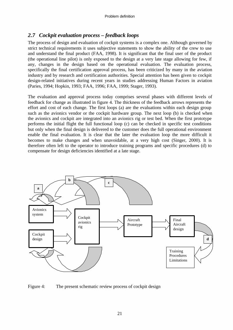
2.7 Cockpit evaluation process – feedback loopsThe process of design and evaluation of cockpit systems is a complex one. Although governed bystrict technical requirements it uses subjective statements to show the ability of the crew to useand understand the final product (FAA, 1998). It is significant that the final user of the product(the operational line pilot) is only exposed to the design at a very late stage allowing for few, ifany, changes in the design based on the operational evaluation. The evaluation process,specifically the final certification approval process, has been criticized by many in the aviationindustry and by research and certification authorities. Special attention has been given to cockpitdesign-related initiatives during recent years in studies addressing Human Factors in aviation(Paries, 1994; Hopkin, 1993; FAA, 1996; FAA, 1999; Stager, 1993).
The evaluation and approval process today comprises several phases with different levels offeedback for change as illustrated in figure 4. The thickness of the feedback arrows represents theeffort and cost of each change. The first loops (a) are the evaluations within each design groupsuch as the avionics vendor or the cockpit hardware group. The next loop (b) is checked whenthe avionics and cockpit are integrated into an avionics rig or test bed. When the first prototypeperforms the initial flight the full functional loop (c) can be checked in specific test conditionsbut only when the final design is delivered to the customer does the full operational environmentenable the final evaluation. It is clear that the later the evaluation loop the more difficult itbecomes to make changes and when unavoidable, at a very high cost (Singer, 2000). It istherefore often left to the operator to introduce training programs and specific procedures (d) tocompensate for design deficiencies identified at a late stage.
Figure 4: The present schematic review process of cockpit design
Avionicssystem
Cockpitdesign
Cockpitavionicsrig
AircraftPrototype
FinalAircraftdesign
TrainingProceduresLimitations
a
bc
d

Problem definition
22
2.8 “Band-Aid” fixesThe present method of evaluating a commercial cockpit design is based on contractualrequirements, time and scope constraints and the trend to minimize certification risks. Unlike thelarge manufacturers, the majority of the airframe manufacturers have infrequent new projects,limited research resources and compressed test schedules (Singer, 1992; Singer, 2000). Incontrast to most military projects, commercial ones usually allow only two years for design andone year for development and certification flights (Singer & Persson, 1996). Due to these timeconstraints, very little experimentation is done for validation of new design features andapprovals are made based on "Good Engineering Practices". In many cases the evaluations aredone using paper mock-ups or early prototypes and the final result is forced through thecertification process as "Good Enough". Despite test pilot protests, error-prone design featuresare approved due to the lack of a "Certification Paragraph" that could be used to enforce achange. Test teams are often faced with a more or less finished design and have very little roomto mandate changes.
The constraints above have contributed to cockpit design solutions that lack a formal validationand therefore probably incorporate deficiencies that might cause or facilitate crew errors(Courtney, 1999). Some would claim that such error risks will usually be captured by other safetynets such as procedures and training but how reliable are these nets? This has been explored bymany including representatives of the certification authorities (Newman, 1997).
2.9 Training to cover for design flawsWhen the design finally enters service, it often lacks the full means of training anddocumentation. The manufacturer of a new aircraft is required to comply with the airworthinessregulations but much more is needed for the efficient use in service. Training requirements forthe crew are not part of the mandatory Airplane Flight Manual (AFM) and usually requireextensive work by training centers and airlines to be made complete. A training simulator mightnot be available prior to introduction into service and detailed design philosophy and trainingneeds are not specified. This issue, when not taken into account during initial evaluations, maycontribute to extra risks due to errors made by the new users.
The general goal of training is to improve response reliability and robustness of failuremanagement and increase anticipation of alarm situations to the point of creating an ideal alarm-less environment. There seems to be a gap between designers and training pilots when it comesto the level of system understanding required. Addressing the training issues early in the designprocess and publishing a clear system philosophy to the users will help eliminate such gaps.
2.10 Inadequacies of the evaluation methods presently used by industryThe following examples illustrate the process used by the aircraft industry to show compliancewith the present design requirements. These examples illustrate the typical small scalemanufacturer and do not criticize the larger manufacturers that usually have more leverage toforce tailor-made designs. Furthermore, the role of the test pilot in each method is highlighted fordiscussion reasons.
2.10.1 Cockpit ergonomicsOne of the first tasks of the test pilot in a new project is to evaluate mockups and prototypes ofthe cockpit and its levers. For flying the aircraft, the most important control features in a cockpit
Problem definition
23
are the primary controls usually called the control-column or control-wheel. In most commercialaircraft (Airbus 320/340 family is an exception), pitch and roll are determined by the pilot bymoving a control column forward and aft and rotating a control wheel left and right. The positionand size of the wheel is central in the design of the whole cockpit and requires a thorough andsystematic evaluation throughout the design and development process. The designer must assurethe full travel of the controls when a pilot is seated, that the cockpit displays are not significantlyobscured by the controls in any position and ensure the crew ability to egress the cockpit.
All of the above can be evaluated in a partial cockpit mockup. By selecting evaluation pilots ofdifferent sizes and percentiles (including some with extreme combinations) the ability to use thefull travel of the controls and reach the rest of the cockpit functions is evaluated. Since the pilotseat can be adjusted in several degrees of freedom, it is essential to determine that all evaluationsare done using the pre-determined position that is equivalent to all pilots. A Design Eye Point, athree-dimensional position in the cockpit, is defined as a point where it is assumed all pilots canposition themselves and perform all duties (FAA, 1998). This position is also the onedetermining the other display positions and the field of view available out of the cockpitwindows. Even though full travel of the controls can be determined in such a mockup, the forcesrequired for moving the controls are not fully defined (for reversible controls) until the flight testphase. The smaller the size of the control wheels, the less it obstructs the pilot’s view. On theother hand, a small wheel results in a shorter moment arm between the pivot and the pilot handsthus requires higher forces (Singer, 2000).
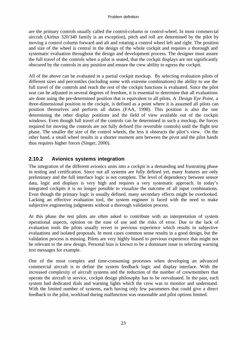
2.10.2 Avionics systems integrationThe integration of the different avionics units into a cockpit is a demanding and frustrating phasein testing and certification. Since not all systems are fully defined yet, many features are onlypreliminary and the full interface logic is not complete. The level of dependency between sensordata, logic and displays is very high and requires a very systematic approach. In today’sintegrated cockpits it is no longer possible to visualize the outcome of all input combinations.Even though the primary logic is usually defined, many secondary effects might be overlooked.Lacking an effective evaluation tool, the system engineer is faced with the need to makesubjective engineering judgments without a thorough validation process.
At this phase the test pilots are often asked to contribute with an interpretation of systemoperational aspects, opinion on the ease of use and the risks of error. Due to the lack ofevaluation tools the pilots usually revert to previous experience which results in subjectiveevaluations and isolated proposals. In most cases common sense results in a good design, but thevalidation process is missing. Pilots are very highly biased to previous experience that might notbe relevant to the new design. Personal bias is known to be a dominant issue in selecting warningtext messages for example.
One of the most complex and time-consuming processes when developing an advancedcommercial aircraft is to define the system feedback logic and display interface. With theincreased complexity of aircraft systems and the reduction of the number of crewmembers thatoperate the aircraft in service, cockpit design philosophy has to be reevaluated. In the past, eachsystem had dedicated dials and warning lights which the crew was to monitor and understand.With the limited number of systems, each having only few parameters that could give a directfeedback to the pilot, workload during malfunction was reasonable and pilot options limited.

Problem definition
24
With the introduction of advanced glass-cockpit aircraft using highly automated engines andflight control systems, the situation changed. The systems were integrated in such a way that onefailure could cascade into multiple failures of other systems. In addition, the sensing andmonitoring features became more capable and could display the detailed faults and system status.The result was an overload of warning information in the form of audio and visual feedback tothe crew at critical stages of the flight like in the case of the MD80 accident in Sweden 1991(Mårtensson, 1995).
As a method of design, the manufacturer looks at the possible failure cases for each system, theexpected effects, and the way the crew is expected to react and show compliance with the writtenrequirements. In addition, test pilots are involved in the determination of the system interfacesuitability in all foreseeable conditions (displays, audio sounds and tactile feedback). Since thematrix of all combinations is endless, safety analysis is made to isolate the most probable failuresand the ones with the most severe effects.
2.10.3 Flight testingTraditionally, flight test has always been assumed to be the best method to evaluate a system,since it is tested in end-to-end operations in actual flight conditions. Typically, following aground test period on the aircraft prototype, the system is found safe to fly and the test teams aregiven the task to evaluate its usability in flight. Most test version systems have many deviationsfrom the final product but the basic function is usually available. Therefore many restrictions areset on flight test configuration, limiting testing scale and exposure to less than the full envelope.Nevertheless, flight test is in many cases the best tool for the task.
The flight test technique used by the test pilots for evaluating control characteristics requiresprecision and patience. It is the pilot’s task to help define the most critical conditions for the testto cover all foreseen future flight conditions. In many cases the flight test methods succeed inidentifying problems and result in changes that make the control response acceptable for use inall foreseeable conditions. In several examples (Singer, 1992) the flight test method failed to givethe expected results in time and the project suffered considerable delays. High fidelity simulationbased on a more detailed aerodynamic model would allow an earlier fix and could contribute to abetter initial product.
2.10.4 Certification criteriaAny aircraft in service must meet rules and regulations set by the aviation authorities. In theWestern world today, most countries follow the rules set by the American Federal AviationAdministration (FAA), the Joint Aviation Authorities (JAA) for most European countries, orclose derivatives of these rules. The airworthiness rules guaranty that the aircraft will be designedto certain standards, and meet minimum system safety levels and aircraft control in allforeseeable conditions. In the case of large commercial aircraft (above 5.7 tons) the set ofrequirements are called Federal Aviation Regulations Part 25 (FAR 25) or the JointAirworthiness Requirements (JAR 25).
The fact that an aircraft is built to the airworthiness standards does not clear it for operations.Separate requirements exist for each nation and type of operations that mandate the rules set forthe airline regarding aircraft equipment; it’s use, crew training, duty time, maintenance etc. In theUSA operational rules for airlines are regulated by FAR 121 or FAR 135 and in Europe by JAR-OPS. The mandatory FAR/JAR 25 paragraphs are usually very generic regarding new

Problem definition
25
technologies. Nevertheless, when applying for approval of a new interface installation, severalFAR/JAR rules must be complied with (Singer & Dekker, 2001 – Paper B).
The vague rules and guidelines show the difficulties in showing specific compliance especiallywith the introduction of complex integrated systems. The terms ease, smoothness andpositiveness used in the regulations are inherited from the traditional cockpits with mechanicallevers, switches and buttons. In the domain of electronic screens and keyboards the FAR/JAR 25(FAA, 1998) requirement is very vague since feedback from computers is rarely felt. How dothese terms translate into software dialog on a modern display? Modern cockpits require almostno physical effort, but the means of measuring mental fatigue are not described and neither is theacceptable level stated. How should one use these requirements to determine reasonableconcentration of fatigue when programming an obstinate FMS in difficult flying conditions?
The system designer or evaluator is faced with the impossible task of showing that theinstallation provides convenient operation and prevents confusion and inadvertent operation. Theterm prevent, if interpreted as an absolute state, will make a design of a complex interfaceunrealistic.
Labeling of controls is a straightforward rule regarding normal cockpit controls. But how doesone define labels on an electronic display? When checking existing displays, it becomes clearthat although partially addressed in the advisory material such as AC 25-11 (FAA, 1987), there isno standard and that more guidance on means of compliance is needed. For example, terms likeeffect of error should be used and what tests the design has to pass be shown. The requirement tofunction properly when installed is easy to evaluate on mechanical levers, but how can this beachieved with any certainty on an FMS? In the PC environment, display architectures havebecome standardized to some extent following the international standards for Visual DisplayTerminals (VDT) (ISO 9241, 1997-1998). Such guidelines are missing for cockpit interfacesystems like the FMS.
How can one determine what is simplicity and how much training is needed for the crew to reachthe level of ease stated in this requirement when existing practices, routines and vulnerabilitieschange as a result of the introduction of a new technology? In general pilot skill is not definedsufficiently and no criteria are stated as to the adequate levels required to operate a new novelsystem safely.
2.10.5 Certification flightsThe certification authorities are faced with a dilemma concerning the interpretation of the rules.Their task is to check compliance with regulations that are often outdated and irrelevant for thenew design. General rules requiring ease of use for example, lack a fail/pass criterion that hasbeen shown to be accepted by previous validation. The reliance on older design solutions is oftenused to approve new designs based on the so-called Grandfather Rights. When a manufacturerapplies new design features that might reduce the susceptibility to human error, it is unclear whatkind of certification credit these features might give the design. The lack of objective criteriaresult in the introduction of special conditions and issue papers that try to fill in the gaps in theregulations. Since these papers are usually ad-hoc, suggested requirements were not consideredduring the design phase and conflicts tend to rise. Certification flights of failure modes areusually done after a proper briefing, using a build-up approach and by trained crews. Thecertification pilots are then asked to extrapolate the results to an operational environment and thetypical end user. These assumptions are subjective and may vary significantly between

Problem definition
26
certification teams. The unpredictable results increase the project risk since early ruling isdifficult to attain. Many high-risk certification tests are done in engineering simulators in order toexpose the systems to the limits of the envelope. These tests require a simulation tool validated tosatisfy the needs of the specific tests. The need to achieve high fidelity in simulation at an earlystage of a new aircraft project may delay the use of the simulator and result in late or incompleteevaluations.
2.11 SummaryThe current methods of validating the design and usability of a new cockpit are not sufficientwhen evaluating the new complex systems in a modern commercial aircraft. The followingsummarize these issues:
• Usability Tests are made on subsystems in isolation with the final design. The full extentof the system interface and complexity is seldom implemented in these tests.
• The tools used usually display static conditions and in many cases consist of a paperschematics or Boolean logic only.
• The evaluator, often a test pilot, is asked to answer in a subjective manner since objectivecriteria are often not agreed upon.
• New and novel features such as highly automated controls and displays, contain newpotential risks that are difficult to identify and quantify using the traditional evaluationmethods.
• The evaluator is asked to make predictions as to possible use and misuse by operators ofdifferent background and culture. This type of extrapolation and prediction of humanbehavior is not the main expertise of a test pilot.
• Typical evaluation results are very subjective and difficult to substantiate in a manneraccepted by design engineers and managers. The lack of clear and specific rules makesthe task of the evaluator very demanding and places a very large burden on each decision.
• Evaluations are often made without the end user and only by very few evaluators that arealso involved in the initial design. This causes a risk for bias that is not counterbalancedin a scientific way.
• Existing research methods are usually not implemented by the industry due to high cost inresources and schedule.
• Finally, when deficiencies are discovered in the final product, the fixes that can be madeare often not design ones but rather more training, complex procedures and introductionof operating limitations.
Research Proposal
27
3 The research proposal of the thesis
3.1 Aim of the thesisThe present process of validating cockpit system design features from a usability and reliabilityaspects has been shown to require improvements to cope with the complexity of the modernsystems. This thesis proposes a new process for future cockpit design validation process that willassist in achieving a more reliable and systematic means of predicting cockpit usability andsafety at an affordable effort to industry. The aim is to describe, test and discuss a quantitativecockpit-design validation process as found practical from the view point of the manufacturer ofcommercial aircraft.
3.2 The scopeThe thesis is based on empirical results of several part-task simulations used in a manner suitablefor aircraft project dynamics. In parallel, new methods for addressing crew error risks and thevalidation of such assumptions are described and discussed. An effective method of involving theline pilot in usability and workload simulations is explained and the reasons discussed. A newrole for the test pilot is proposed in light of past experience and need of more reliable validationtest runs. In order to structure this process and implement it equally in all future projects, thecertification rules and advisories are addressed and the work done by the HF-HWG described.
3.3 MethodologyThe thesis combines the development of a new process based on original evaluation and analysisof existing problems and the use of empirical results using the tools proposed in the new process.The author uses original results of part-task simulation experiments together with the products ofworking groups that he was part of. The thesis consolidates the results and proposals of theindividual papers and adds an in depth analysis of the new validation process. The summary ofthe combined methods could be described as the aim to use the best tool for the task at any giventime during the development and certification of cockpit design.

Human factors theories and methods
28
4 Human Factors theories and methods in aviationExtensive research has been done in the field of Human Factors in general and investigatingcockpit issues in particular. In order to explain the innovative features and their application asproposed in this thesis, some of the theoretical work done in the field will be discussed and themissing method characteristics highlighted.
The scope of this thesis is limited and cannot cover reviewing all previous research in the field ofHuman Factors related cockpit design and evaluation. The attached papers try to cover more ofthe relevant research (Singer & Dekker, 1999 - Paper A; Singer & Dekker, 2000 - Paper B;Singer & Dekker, 2002 - Paper D). In order to show why most research results are not used byindustry, a sample of such results, mainly in the area of alerting and warning, will be discussed inthis section.
4.1 The paradox of information displayThe highly automated systems in a cockpit are capable of collecting and presenting a vast amountof information regarding aircraft system status and predictions at a very high level of detail(Figure 5). The user on the other hand, has maintained the same capacity of perceiving,understanding and reacting to this information. This leaves the designer with a paradox of notbeing able to use all the system capabilities. The art of design becomes the ability to make thecorrect compromise between the type, quantity, and timing of information display. Not only isthat task very demanding, it must be considered taking into account the dynamic change of flightconditions. The physical characteristics of each flight phase are known but still under debate arethe combinations of atmospheric conditions, flight conditions and system failure modes to beused for validation. Since even these parameters can be quantified, it might seem like a solvableproblem. The issue that has been the concern in recent years is more the ability to predict crewperception and workload due to the information that is displayed (Woods & Sarter, 1998). On theone hand, the pilots’ request to be kept in the loop and have good situation awareness while onthe other, only relevant information is wanted (Mårtensson & Singer, 1998). The definition ofrelevant information changes with stress and workload and has been found difficult to determine.
Figure 5 Typical electronic displays with multiple features(Honeywell International EPIC - Do 728)
Human factors theories and methods
29
4.2 Warnings and risk communicationRisk evaluation and warning system principles are not unique to aircraft cockpits. The conceptof warnings and the communication of risk are well established in many other fields. In the bookWarnings and Risk Communication (Wogalter et al., 1999), many of the aspects of how tocommunicate warnings and risk information to be effective, and what factors influence thecommunication process are explored in detail. The book covers many fields with illustratedexamples that relate mostly to traffic signs, medicine and food labels and other conventions. Thegeneral method is based on a model called Communication-Human Information Processing (C-HIP) that includes: Source, channel, attention, memory, attitudes, motivation and behavior assteps in a framework.
The authors describe the methods of assessing attention in the context of warnings. Attention canbe measured more-or-less directly by tracking eye movements, measuring detection alternativelyreaction times or by self-reporting of attention. These three most common methods for measuringattention have their benefits and drawbacks.
Ø The eye movement method is probably the most direct method of assessing visual attention.This method is a good measure especially for investigating the pre-attentive aspects ofsalience manipulators (border, icon, and color or signal word) and how they draw attentionwhen they pop-out. While very attractive for use because of the exact results, the eye trackingexperiments are very expensive and data collection can be time consuming.
Ø Detection or Reaction Time (D-RT) is another direct method of measuring attention. While itis much easier and cheaper to use, the drawback is that the researcher does not gaininformation about the visual path taken in order to locate the warning. In addition,participants can falsely report having detected the warning.
Ø The Self-Reports method involves asking the participant questions whether they saw thewarning or not. This method should be used only in context of memory studies, but not as ameasure of pure attention due to possible bias.
Warnings and Risk Communication describes the different components of comprehension inregards to warning messages. Readability, coherence, explicitness and brevity are importantissues when looking at verbal messages. If pictorial symbols are used it is important to know thetarget user population, their experience with the product, competence (ability to read) and hazardperception. Memory can be measured by open-ended recall, which is asking the participants torecount all they remember. It is usually more important that people remember the idea (lenientscoring) rather that the exact text (strict scoring) of the warning. Another method of checkingmemory is by recognition tests. These tests are more realistic than memory recall since safetywarnings are supposed to cue people about potential hazards. Matching techniques may also beused but it does lend itself to guessing.
What we as humans perceive as the truth is often only attitudes and beliefs. This is veryimportant to remember in order to understand risk perception when evaluating a warningmessage. Beliefs are any cognitive content, which is held as being true. If people do not believethat they need to take precaution, they will ignore the warnings.
The authors of Warnings and Risk Communication also treat methods in which one can evaluatecompliance with warning information and signs. One method used is called the IncidentalExposure, where the participants are not informed that the study deals with warnings. Instead a

Human factors theories and methods
30
cover story is given and behavior is expected to be more as in real life. The method might beincluding deception, which requires consent and approvals.
In summary, the authors state that little research has been done regarding how warnings influencebeliefs and attitudes. This is a very important issue in the cockpit where very determined andstrong willed individuals communicate. Despite the relevance of many of the findings describedabove very little implementation of such methods has been seen in the aviation industry. Theissues of language, belief, or even pure recall issues are not part of an approval process. Is it thelack of time or the lack of a requirement to do so? Could general rules of design be implementedto the aircraft world or is it too unique in it’s environment?
4.3 Addressing human errorHuman error has been deeply investigated for its causes by Reason (Reason, 1990) and severaltheories produced. The well known “Swiss Cheese” model illustrating the defenses that preventan accident from occurring is one relevant for cockpit design. The model divides errors intoseveral subsets of behavior but does not quantify or specify the means to determine the size ofthe holes in the cheese slices. In a recent paper addressing the classification of human behavior, ateam from the University of Illinois Aviation Research Lab (Shappell et al., 2001) explain a newHuman Factors Analysis And Classification tool (HFACS). The tool uses data gathered duringaccident investigations and develops the human error classification proposed by Reason intomore operational related errors. Errors are separated from violations and each group addressed indetail. This process helps to focus on areas that require training of skills and supervisionprograms. The weakness in this method is its reliance only on past accidents and its lack ofreference to cockpit technology (especially novel features). In addition, the problem remainsregarding what level of training is needed for safe operations and how to test trainingeffectiveness in a reliable way (Rignèr & Dekker, 1999).
In the article Coping with Complex Alarms (Gibson, et al., 1996) the authors discusssophisticated alarm systems in aircraft. They propose some recommendations for changing thetraining strategies. They state that the foundation of advanced training is that crews need to knowmore than merely how to work the system in order to diagnose problems. They must havesufficient knowledge about the system functional levels down to the level where they can have aneffect on the outcome. This will help their mental model and reduce the risk of commissionerrors.
A new approach of addressing human error as part of the design safety analysis has recently beenproposed by the CAA (JAA NPA, 2001). It goes the partial step of recommending the insertionof all human errors into system safety analysis. What is missing from the proposal is theidentification of levels of risk introduced by these errors, whether in normal operations or errorsfollowing system guidance.
4.4 Human performance using warning systemsIn his book Engineering Psychology and Human Performance (Wickens, 1992) the authordescribes solutions to some of the problems pilots are faced with in fault management. Errortolerance and prediction capabilities are expected of future warning systems. The aim is to allowthe operator to experiment with the control of variables and predict their outcome beforecommitting to the action. The system will predict the results and the crew can determine whetherto accept or take another action.

Human factors theories and methods
31
The way an alarm is annunciated today, by very annoying alarms, guaranties detection but mightbe counterproductive to effective diagnosis. Diagnostic aids should be given more attention.Sequencing, is suggested as a method of for example replaying the event at pilot’s choice.Prioritizing and grouping are techniques used already on existing systems, but in a way ofspatially organizing the display as to show systems that are closely related as a single globalvariable that is easier to monitor. The author describes display integration where emergentfeatures, which are the size and shape of an object, will show early trend changes of the status ofa system. The meaning of color should not only to be status related but also be dependent on theoperational phase.
Prioritization logic has been implemented in most aircraft system designs but grouping and errortolerant designs have not been systematically implemented yet, partly due to other constraints(commonality with older models, space, cost). One reason might be that pre-design activities arevery limited, the subsystems are designed by independent vendors and the philosophy of asystem usually takes form too late for significant changes.
4.5 Validating simulators for Human Factors useMission Oriented Simulators (MOS) are often used in Human Factors research. The level offidelity needed for such research is evaluated in a National Aeronautics and SpaceAdministration (NASA) paper (Orlady et al., 1988), guidelines for conducting such researchdetermined and recommendations for alternative methods given to improve researchproductivity. The paper gives very valuable inputs to researchers using simulators and provideschecklist and tips for test teams.
The Mission Oriented Simulation method gives the opportunity to determine which level ofsimulation is sufficient and for what purposes and scenarios. The idea is to validate data ofseveral devices (from full simulator to part-task PC). In this approach flight-testing is required togather actual flight data of the scenarios. It is then necessary to validate the behavior of thesimulations in each required test condition. If the expected characteristic does not appear in thesimulation, the fidelity is probably insufficient. Since some deficiencies will not be seen byobjective tests, subjective evaluations of Subject Matter Experts (SME), such as pilots, areneeded for a complete validation.
Another aspect of MOS is the pilots’ acceptance of the scenarios and representations. It wasfound that while accepting deficiencies in simulation fidelity, pilots did not tolerate unrealistictasks and scenarios. NASA therefore recommends that the overall conditions leading to tacticaland strategic decisions must be realistic in order to test failure conditions. One last commentregarding simulations is the need to avoid exposing the crew to experiences that might bepsychologically damaging, such as a crash of a fully loaded large transport aircraft.
Limited simulation tools have been used in most recent aircraft projects. The main aim has beento look at flight controls interface and handling characteristics prior to flight (Singer & Persson,1996). The use of simulation for display and logic verification has been limited to Bench Testingof local interfaces rather than a full aircraft layout. The reason being the difficulties in validationof the simulators in order to get credit for test results based on those tools only. It was oftenfound that the complexity of the system and its integration with other aircraft sensors made theinvestment unreasonable and therefore the actual aircraft was used as a simulator for limitedtesting prior to flight.

Human factors theories and methods
32
4.6 Evaluating integrated information systemsIntegrated Crew Information System (ICIS) evaluation program is an example of a veryprofessional and pragmatic method of evaluating a new display used for presenting informationto the crew including guidance how to address failures. The ICIS paper (ICIS, 1997) covers twomethods for evaluation of a new display concept, the first using a full-mission simulator, and thesecond using a part-task evaluation for specific tasks. This goes well in line with the NASArecommendation (Orlady et al., 1988) but takes it a step further by involving the full scale of endusers in a very scientific way.
The ICIS evaluation method is structured in such a way that it set defined measures ofperformance and set pass/fail criteria prior to the evaluations. The dimensions to assess successcriteria were acceptability, usability, efficiency and safety. Each measure was evaluated by usingeither questionnaires or measuring crew errors and rating them according to criticality levels. Thecare taken to choose a representative population large enough to draw solid statisticalconclusions makes this method very robust and validity level assessed as very high. 72crewmembers were tested in a training simulator and evaluated by post-flight questionnairesincluding the well-established Task Load Ratings (TLX) and Situational Awareness RatingTechnique (SART) methods (Wilson & Corlett, 1995). One of the important issues that wereaddressed was that the errors in themselves should not always be a concern. It is rather the effectsor criticality of error that should be evaluated, and attention given mainly to the ones reducingsafety and efficiency.
As a complementary method to the full-mission simulator, a more limited and controlledenvironment was set to validate the effects of each parameter using a part-task simulator. In thisenvironment, specific items such as response to predetermined conditions were evaluated closelywithout the constraints of the multiple tasks the crew is asked to solve in the first evaluation. Inthis scenario the task performance of the new display can be evaluated and retrieval ofinformation documented.
Taken together, the full-mission Simulator and the part-task evaluations constitute a structuredmethod with objective criteria and measurement of performance for evaluation of fitness as anew display in a modern cockpit. Industry has not adapted this method probably due to cost andschedule constraints and as long as designs can be approved without simulations it seems like therisk is assumed to be acceptable. The manufacturer of the ICIS that went into the effort of asystematic evaluation process was forced to abandon the project and ceased to exist. The cost inresources and schedule seem to be one of the obstacles in industry accepting such comprehensivemethods.
4.7 Decision aids for the complex cockpitIn modern complex cockpits, the crew is required to absorb many pieces of information often intime critical conditions. In several papers on Model Based Reasoning (MBR) applied to cockpitwarning systems (Ovenden et al., 1993; Noyes et al., 1995; Ovenden, 1993), the authors describethe advantages of using MBR techniques as a method of making warning systems more“Intelligent”. The cases when multiple failures occur simultaneously are discussed and thepotential of conflicting procedures highlighted. It emphasizes the importance of ensuring thatappropriate warning system information is presented in a form that the individuals can readilyunderstand.

Human factors theories and methods
33
MBR provides a novel approach to warning system design and is in general based on a systemmodel representing the correct function of each condition. By comparing actual behavior to themodeled one, early trends of failures or abnormalities can be detected and the crew informed.Unlike conventional systems that are fault oriented, the Model-Based system can take intoaccount broader goals such as strategic inputs, navigation, fuel left etc. A detected discrepancycan be identified and categorized (convergent, divergent, stable, oscillating) and the relation tothe predicted model displayed.
The main advantages of this method are claimed to be the early detection and reaction to slowand non-linear parameter changes that would usually have gone undetected until developed into amore serious condition. Finally, the method allows a more flexible and goal driven prioritizationto be programmed that will reduce pilot workload and improve decision support in cases ofcomplex failures. This method has been partly used in the integration of a warning system into ahelicopter project. The reluctance of industry to have a more widespread use of predictivesystems is the long development and testing time needed and the risk for large number ofnuisance warnings when entering service. As long as no specific requirements are set by the useror the authorities the manufacturer will probably take the low risk approach to design. In manycases the added value of an early predictive warning is questioned by the operators. It mightcause larger number of diversions or flight cancellations that are not directly flight safety related(Nibbelke, et al., 2000).
4.8 User involvementThe research method based on User involvement (Noyes, Starr & Rankin, 1996; Noyes, Starr &Frankish, 1996), shows advantages of using pilots in the design process. Unlike the ICISexperimental method (ICIS, 1997) described above, this method uses the pilots for knowledgeelicitation in the early stages of a project. More than 1300 questionnaires were evaluated andanalyzed. The pilots represented were the typical end user population using modern systems, andflying different types of aircraft. By defining criteria and addressing the different functions ofwarning systems for example, designers can improve the features of future warning systems totake into account present deficiencies. By getting a large sample of pilots, the risks of bias andother validity risks (Cook & Campbell, 1989) are minimized and external validity of the results issecured. In order to ensure the robustness of the widely spread questionnaire, a semi-structuredpre-study interview process using smaller numbers of participants was performed. This allowedthe team to evaluate the comprehension, semantics, style and content of the questionnaires. Aftercompleting the analysis of the questionnaire results, the team returned to a small sub-sample offlight deck crew to check the validity of the results.
This method is sensitive to interpretation of terms and scenarios but the use of the three-stageinterview method (Noyes et al., 1995) assures that the user-interface will also be user-oriented inthe design. Unfortunately, such broad subjective methods require unacceptable time andresources from a competitive industry and unless a simpler and much more limited method canbe provided, this will remain a method used for research. It would be helpful if genericrecommendation could be implemented in certification guidance material as an aid in a designprocess.
Human factors theories and methods
34
4.9 Implementation by industryWhen reviewing all the research done regarding Human Factors aspects of cockpit design issues,it is surprising to notice that very few of these methods and results have been implemented in theaircraft industry. Although the large manufacturers do engage in research projects with severalknown institutes, the final design products show very little traceability to such research (FAA,1996; AIA/AECMA, 1998).
A positive example though is the cooperation between industry and researchers (Boeing &Massachusetts Institute of Technology (MIT)) in the study which focuses on the display featuresof the new terrain displays (TAWS) (Kuchar & Hansman, 1993) introduced in the last few yearsinto all large aircraft. The research gives concrete results to industry on the best method todisplay terrain by providing pilot ratings and pilot response based on part-task simulation. Thegeneral conclusion was that the plan view (map like) display was best perceived by the pilots andalso showed best avoidance response. Even though some of the issues were not fully covered, itseems like most of industry selected to pursue this track and present terrain (TAWS) in the mapmode.
Despite all these research examples, very little has been used by industry when approaching thedesign of a new cockpit. Some large manufacturers might have used structured methods butmany smaller ones have not. The author’s personal involvement in the development andcertification process at SAAB Aircraft and Fairchild-Dornier shows very little has been done inthe way of a structured Human Factors cockpit evaluation process or implementation of externalresearch results.
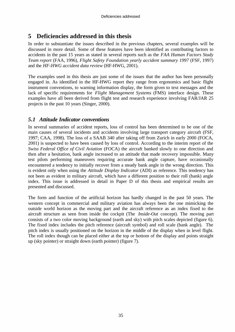
Deficiencies addressed
35
5 Deficiencies addressed in this thesisIn order to substantiate the issues described in the previous chapters, several examples will bediscussed in more detail. Some of these features have been identified as contributing factors toaccidents in the past 15 years as stated in several reports such as the FAA Human Factors StudyTeam report (FAA, 1996), Flight Safety Foundation yearly accident summary 1997 (FSF, 1997)and the HF-HWG accident data review (HF-HWG, 2001).
The examples used in this thesis are just some of the issues that the author has been personallyengaged in. As identified in the HF-HWG report they range from ergonomics and basic flightinstrument conventions, to warning information display, the form given to text messages and thelack of specific requirements for Flight Management Systems (FMS) interface design. Theseexamples have all been derived from flight test and research experience involving FAR/JAR 25projects in the past 10 years (Singer, 2000).
5.1 Attitude Indicator conventionsIn several summaries of accident reports, loss of control has been determined to be one of themain causes of several incidents and accidents involving large transport category aircraft (FSF,1997; CAA, 1998). The loss of a SAAB 340 after taking off from Zurich in early 2000 (FOCA,2001) is suspected to have been caused by loss of control. According to the interim report of theSwiss Federal Office of Civil Aviation (FOCA) the aircraft banked slowly to one direction andthen after a hesitation, bank angle increased to an attitude that made recovery impossible. Manytest pilots performing maneuvers requiring accurate bank angle capture, have occasionallyencountered a tendency to initially recover from a steady bank angle in the wrong direction. Thisis evident only when using the Attitude Display Indicator (ADI) as reference. This tendency hasnot been as evident in military aircraft, which have a different position to their roll (bank) angleindex. This issue is addressed in detail in Paper D of this thesis and empirical results arepresented and discussed.
The form and function of the artificial horizon has hardly changed in the past 50 years. Thewestern concept in commercial and military aviation has always been the one mimicking theoutside world horizon as the moving part and the aircraft reference as an index fixed to theaircraft structure as seen from inside the cockpit (The Inside-Out concept). The moving partconsists of a two color moving background (earth and sky) with pitch scales depicted (figure 6).The fixed index includes the pitch reference (aircraft symbol) and roll scale (bank angle). Thepitch index is usually positioned on the horizon in the middle of the display when in level flight.The roll index though can be placed either at the top or bottom of the display and points straightup (sky pointer) or straight down (earth pointer) (figure 7).

Deficiencies addressed
36
Figure 6: The two reference methods for using an Attitude Indicator
Figure 7: The Sky and Earth roll pointers (do not appear together)
SETP – Linköping, Sweden© 2001
CHECKPOINT
6 Gideon Singer (M) - SAAB Aircraft AB(project partly funded by the EC)
ADI Conventions
ØThe Moving Part:ØInside-Out:
ØOutside-In:
SETP – Linköping, Sweden© 2001
CHECKPOINT
7 Gideon Singer (M) - SAAB Aircraft AB(project partly funded by the EC)
ADI Roll Index
ØScaleØSky pointerØEarth Pointer

Deficiencies addressed
37
The general Inside-Out convention has been adapted and seldom questioned despite substantialexperimental data from the 1960s (Roscoe, 1968) showing results that favor the oppositeconvention (Outside-In) used in the east. According to modern aviation research the conventionof the moving horizon gives a consistent frame of reference for a pilot sitting in the cockpit butviolates the principle of the moving part (the aircraft banks in reality) (Wickens, 1992; Roscoe,1975; Roscoe, 1980). Since the introduction of Head Up Displays (HUD), the principal ofconformity has made the western ADI convention more intuitive when overlaying the outsideworld.
When investigating the roll index feature in ADI design, it appears that three conventions (figure8 – left to right) are available and being used (Singer & Dekker, 2002 – Paper D):• The commercial concept (roll index at the top – horizon fixed)• General aviation (roll index at the top – aircraft fixed)• The military concept (roll index at the bottom – horizon fixed)
Figure 8: The three methods of displaying roll index on an ADI
Accepting the Inside–Out convention as a given standard in most commercial aircraft, severalother questions arise when investigating the differences between military and commercialattitude displays. The position of the roll index in military aircraft is predominantly the onepointing down (earth pointer) while the commercial one is almost always pointing up (skypointer). General aviation aircraft have been using a third design of the ADI with the roll index atthe top but coupled to the aircraft symbol and showing bank angle Status rather than the Fly-toguidance. In fact, all three display methods use the Status concepts when depicting the pitch
SETP – Linköping, Sweden© 2001
CHECKPOINT
8 Gideon Singer (M) - SAAB Aircraft AB(project partly funded by the EC)
ADI Bank perception
Commercial
Military
GeneralAviation

Deficiencies addressed
38
related scales and index (the aircraft symbol is used as a pitch status in relation to the pitchscale).
Could the convention of displaying the roll index be the reason for temporary loss of bank angleperception when using commercial ADIs?
The issue is that the changes in display technology, the position of the roll index (sky-pointer orground-pointer) or the use of the pointer as a Fly-to index compared with a Status index arerarely evaluated objectively. Simple experiments can point towards the more reliable displaymethod and show what bias previous training might have on the intuitive response in cases ofstress (Singer & Dekker, 2002 - Paper D).
5.2 What information does the pilot need?Information overload in the cockpit of a commercial aircraft during malfunctions or emergenciesis a serious concern, which originates from several aircraft accidents (FAA, 1996; Billings,1997). In one accident case (SAS accident, Sweden, 1991), an MD80 lost thrust from bothengines shortly after takeoff. The crew was presented with an unusual amount of criticalinformation. Visual and aural warnings were given as well as alert messages on the overheadannunciator panel, all at the same time (Mårtensson, 1995). The pilots were overloaded withinformation, and in interviews performed several years later (Mårtensson & Singer 1998), manypilots suggested that information in the warning system should be prioritized in a way that thepilots could perceive it properly and act accordingly (Woods, 1995; Ulfvengren et al., 2001).
The crew alerting systems of the modern transport aircraft can handle almost any malfunctionthat the pilot is expected to deal with. These features are tested, certified and taught to crews insimulator training sessions. There are variations in the philosophy of display of the alertinginformation between the manufacturers but many methods implemented in today’s aircraft showsatisfactory results and good human integration for the task defined (Pritchett, 2001). However,in case of multiple faults in a high workload situation, the warning system of the modern cockpitis not always easy to use and understand. The tendency is to overload the display with warnings,cautions and inoperative system information accompanied by various aural warnings and cues.The pilot becomes overloaded with information and cannot handle all at one time. The result isthat the pilot may disregard the information, return to basic flying, and rely on his ownperception of the situation, a strategy which turned out to be the correct one in the accidentmentioned above, but might have catastrophic effects in other emergencies. This issue isaddressed in detail in Paper A of this thesis and empirical results are presented and discussed.
The present regulations define only few individual warnings in detail (red and amber color use,landing gear warning, etc) (CFR14, FAR 25.1322). Several design standards have beendeveloped, some giving the pilot all the information available (figure 9), some implementing acertain level of prioritization and others providing high levels of automation followed by systemguidance. All of these methods have been approved but none was scrutinized by objective criteriaof fail or pass based on operator response.
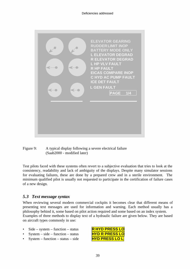
Deficiencies addressed
39
Figure 9: A typical display following a severe electrical failure(Saab2000 - modified later)
Test pilots faced with these systems often revert to a subjective evaluation that tries to look at theconsistency, readability and lack of ambiguity of the displays. Despite many simulator sessionsfor evaluating failures, these are done by a prepared crew and in a sterile environment. Theminimum qualified pilot is usually not requested to participate in the certification of failure casesof a new design.
5.3 Text message syntaxWhen reviewing several modern commercial cockpits it becomes clear that different means ofpresenting text messages are used for information and warning. Each method usually has aphilosophy behind it, some based on pilot action required and some based on an index system.Examples of three methods to display text of a hydraulic failure are given below. They are basedon aircraft types commonly in use:
• Side – system – function – status R HYD PRESS LO• System – side – function – status HYD R PRESS LO• System – function – status – side HYD PRESS LO L
ELEVATOR GEARINGRUDDERLIMIT INOPBATTERY MODE ONLYL ELEVATOR DEGRADR ELEVATOR DEGRADL HP VLV FAULTR HP FAULTEICAS COMPARE INOPC HYD AC PUMP FAULTICE DET FAULTL GEN FAULT
PAGE 1/4

Deficiencies addressed
40
It is surprising to discover that very few experiments have been done in the design phase toevaluate the ease of readability and perception of each display method (Wickens, 1992;Wogalter, 1999). Cultural and language differences are seldom considered when determining textinterface and the assumption is that all users are fluent in the English language (FAA, 1998). Inmany cases the design is driven by the actions the crew has to take (like selecting a certainsystem page) but in others it is more of an administrative decision driven by the ease of applyingan alphabetical index system for documentation. A part-task experiment comparing thesemethods of display will be described later in the thesis.
5.4 The assumptions regarding crew errorWhen addressing crew error, designers are very inconsistent in the way they value crewmonitoring and action. This can be observed in the use of crew procedure as an assumption forsafe operations (the reliance on checklist, airmanship, and crew coordination) or the reliability ofthe crew to follow checklists without error. At present, there is a reluctance to give probabilitynumbers to crew errors since the numbers will be very dependent on external factors such asstress, workload and flight phase. Crew action or error is usually used as a Yes or No (probability1 or 0) for different design requirements. No reference is made to crew violations, that areintentional deviation from learned skills or procedures. At present, good engineering practicesare used to determine which risks are too high and should be mitigated.
For clarity, several examples of conditions where crew error is assumed to be a significant safetyrisk will be specified.
The following are errors that could lead to a catastrophic result (multiple deaths, usually withloss of aircraft). The crew is assumed to make an error and therefore specific rules (FAA, 1998)are set in FAR/JAR 25 that require design mitigation features such as a warning:• Crew fails to extend landing gear prior to landing.• Crew attempts to takeoff with a non- takeoff configuration.• Crew attempts to shut down the wrong engine following an engine fire indication.• Crew exceeds the approved operating speed of the aircraft.
On the other hand the crew is assumed to act correctly in the following. These cases are notspecifically addressed by the rules but have been found to be safety critical in incident andaccident data (HF-HWG, 2001):• Erroneous aircraft weight entry into the FMS (defines the Vspeeds) may result in aircraft stall
at rotation.• Crew attempts to takeoff with a wrong (but approved) takeoff configuration.• Crew attempts to shut down the wrong engine following an engine failure indication.• Crew fails to adjust the rudder pedals or seat to enable full yaw control and risks loss of
control if full control needed due to crosswind of engine failure.• Crew neglects to disconnect the Auto Pilot (AP) at the minimum use height prior to landing
might result in an un-flared touchdown and structural damage.
These examples highlight the need to apply a more systematic approach to crew error, whetherfor errors in normal conditions or error following a system failure. The only valid approachseems to be the future integration of the crew error probabilities (not necessarily as detailednumbers) into the basic system safety assessment. This evaluation will determine whether theeffect of each combination requires a Fool Proof design or whether a warning will be sufficient.

Deficiencies addressed
41
Design solutions can be an indication of the correct lever (fire-handle), a warning when a wrongsetting is attempted (flap selection at an excessive speed) or an inhibition (gear retraction on theground). Each solution has its technical drawbacks in the form of reliability, nuisance warningsand cost. A probabilistic approach to crew error will allow a systematic approach that will befollowed by all and apply the correct levels of defense for each condition depending on thepredicted effects.
5.5 Integration of FMSIn commercial flight, on most modern aircraft today, navigation and flight path are beingcontrolled by a system generally called the Flight Management System (FMS). The interface withthe crew in the cockpit is achieved by an active display called the Control Display Unit (CDU)and is the input/output channel. In addition, the system displays its planned/executed route on aNavigation Display (ND) and flight path guidance by means of a Flight Director (FD) on thePrimary Flight Displays (PFD).
The technical requirements and methods for testing system performance, accuracy and faultanalysis are well established and are defined in the certification material (AC 25-15) for suchsystems and aircraft (FAA, 1998). The methods for technical validation of such systems havebeen used successfully in many types of aircraft avionics and have shown a very high level ofreliability. However, validation of the way the system interfaces with the crew, displaysinformation or reacts to crew inputs is not well defined and each manufacturer or vendor is freeto adapt its own philosophy and methods of showing compliance (Singer, 1999). This issue isaddressed in detail in Paper B of this thesis and the specific design features are presented anddiscussed.
In the late nineties, new Air Traffic Control (ATC) regulations were published that mandate theinstallation of FMS into all aircraft that use medium and upper airspace in Europe (part of JAROPS 1). This produced growing demand for cheap off-the-shelf systems for integration into olderaircraft of all sizes. Many of the transport category aircraft flying today have not been designedwith an FMS as part of the cockpit. Many aircraft are still featuring the so-called classic-cockpitand are lacking the modern avionics bus communication technique used on the integratedcockpits. When such designs are evaluated, it is for the correct function of the system duringnormal operation but not for possible error modes and crew mismanagement.
In order to explain the problem in more detail, examples from present modern FMS designs aredescribed and deficiencies highlighted. The risk involved in these features will be shown andpossible effects of making an error will be discussed.
The CDU is the main interactive interface between the crew and the FMS for programming andchecking performance. The standard interface includes a screen, line select keys, alphanumerickeys, specific function keys and warning lights. This design is typical to all manufacturers, butunlike the typewriter (or PC), there is no standard position for the letter keys. In addition, severalfunction keys have a different use in each design (figure 10). The Navigation (NAV) key forexample; on one design is used for navigating while on another design it is used for planningonly. The Flight Plan (FPLN) keys; on one design are used for planning while on the other theyare used for navigating. These features increase the risk of negative transfer when transitioningbetween systems.
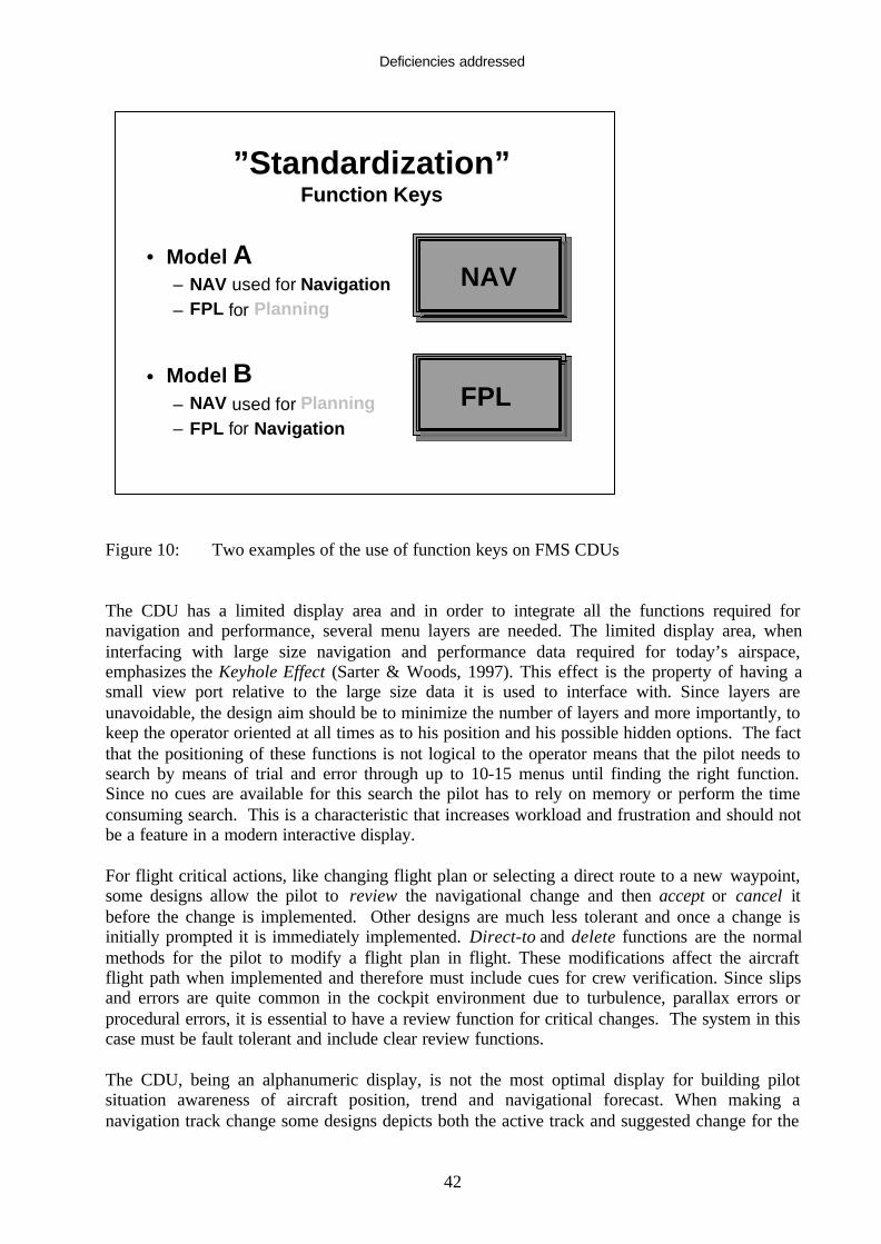
Deficiencies addressed
42
Figure 10: Two examples of the use of function keys on FMS CDUs
The CDU has a limited display area and in order to integrate all the functions required fornavigation and performance, several menu layers are needed. The limited display area, wheninterfacing with large size navigation and performance data required for today’s airspace,emphasizes the Keyhole Effect (Sarter & Woods, 1997). This effect is the property of having asmall view port relative to the large size data it is used to interface with. Since layers areunavoidable, the design aim should be to minimize the number of layers and more importantly, tokeep the operator oriented at all times as to his position and his possible hidden options. The factthat the positioning of these functions is not logical to the operator means that the pilot needs tosearch by means of trial and error through up to 10-15 menus until finding the right function.Since no cues are available for this search the pilot has to rely on memory or perform the timeconsuming search. This is a characteristic that increases workload and frustration and should notbe a feature in a modern interactive display.
For flight critical actions, like changing flight plan or selecting a direct route to a new waypoint,some designs allow the pilot to review the navigational change and then accept or cancel itbefore the change is implemented. Other designs are much less tolerant and once a change isinitially prompted it is immediately implemented. Direct-to and delete functions are the normalmethods for the pilot to modify a flight plan in flight. These modifications affect the aircraftflight path when implemented and therefore must include cues for crew verification. Since slipsand errors are quite common in the cockpit environment due to turbulence, parallax errors orprocedural errors, it is essential to have a review function for critical changes. The system in thiscase must be fault tolerant and include clear review functions.
The CDU, being an alphanumeric display, is not the most optimal display for building pilotsituation awareness of aircraft position, trend and navigational forecast. When making anavigation track change some designs depicts both the active track and suggested change for the
”Standardization”Function Keys
• Model A– NAV used for Navigation– FPL for Planning
• Model B– NAV used for Planning– FPL for Navigation
NAV
FPL

Deficiencies addressed
43
pilot to review prior to activation. This display on the ND gives the pilot a graphical depiction ofthe CDU change in form of a temporary route change overlaying the active route. This featureallows all crewmembers to review the change before activation and has been found to increasesystem fault tolerance. Other designs display the change in aircraft track only after it has beenactivated and executed. Such changes to active flight path without crew confirmation have beenknown to cause confusion and reduce safety margins if error made in congested airspace, asmight have been the case in a Saab340 accident (FOCA, 2001).
Any user of PC software expects an Undo function in order to recall incorrect inputs, whetherthey are due to errors or slips. This function is not a standard feature in CDU software and eachdesign has its own criteria for providing an Undo feature. This feature is lacking even in theflight critical parameters such as Direct-to and Delete of some FMS models.
In order to retrofit existing aircraft, interfaces between Electronic Flight Instruments (EFIS) andFMS of different vendors are becoming more common. This may highlight differences incommunication standards with the effect that the different displays show different colors for thesame waypoint (not fully regulated by Advisory Circular AC 25-11) (FAA, 1987). Combiningthis with aircraft manufacturers who have different color standards, and the resulting displaymight be confusing and misleading. The lack of industry standards for color-coding makes thetask of integrating avionics difficult and usually with unexpected results.

Research methods
44
6 Research methods of the thesisThis thesis uses several simulation tools of different levels of fidelity and dynamics in order toachieve the goals set at several phases of the validation process. The methods are presented inorder of tool complexity and include only the methods that produced new empirical results. Thefirst method is a simple presentation using standard projection methods while the last includes aworkstation based simulation combined with a high fidelity flight simulator.
6.1 Static presentation as a tool for convincing managementThis method was used effectively at the early and intermediate phases of defining the detailedfeatures of new cockpit displays, when long discussions were held in multidisciplinary meetings.A simple example of a design dilemma encountered in a recent project (Do728) was the type oftext format to be used on the displays. The method of displaying text has traditionally usedcapital letters only. This might have been used due to software limitations in early days. Severalresearch results show that a mixed font is easier to read, especially for longer text messages(Wickens, 1992; Wogalter et al., 1999).
In order to convince the management of a new aircraft project to implement theserecommendations and go against the common display standard of all other aircraft, a quicksimulation was used for demonstration purposes. The two methods of display were projected fora short duration to a group of a dozen design and management decision makers by using simplePC software (figure 11). The ability to recall and understand the text was tested simply by askingthe meeting participants, including managers, to write down from memory what they could recallfrom a typical display of a set of messages projected. The results from the two display methodswas then compared by checking the number of correct messages recalled.
L E levator FAILRudder Limiter INOP
APU Generator FAILL Eng Sensor A FAILAFT Cargo Fire Det FAILEss Bus 1 Volt LOFuel Balance Pump ONL Hyd Stby Pump FAULT
L ELEVATOR FAILRUDDER LIMITER INOP
APU GENERATOR FAILL ENG SENSOR A FAILAFT CARGO FIRE DET FAILESS BUS 1 VOLT LOFUEL BALANCE PUMP ONL HYD STBY PUMP FAULT
Figure 11: Two methods to display text (upper and mixed case)
Research methods
45
6.2 PC slide-show for comparing display featuresThe PC based simulation tool allows each engineer to test system display assumptions on pilotsprior to committing to the design. Such a tool is readily available on each desk and easy toprogram. The intention is to use it as a comparative tool between several ideas at the initialphases of design (Orlady et al., 1988). During the development phase of a new aircraft displaysystem (Do728), several methods of constructing messages were suggested. It was observed thatall were used in existing aircraft and no data was available to show advantages of one over theothers.
Based on a part-task simulation methodology, a simple tool was constructed aimed at exposingpilots to the three display methods and attaining objective performance results. This method wasused to compare warning messages with different syntax to determine the best method from aperception point of view. The experiments were run using randomly chosen training pilotsvisiting the training center without the need for any formal or preplanned commitments. Thesimplicity of the experiment, the simple briefing and autonomy of the sequencing allowedperforming the tests with minimum interference from the test conductor.
The simulation used a PC based slide show program to run an automatic test without the need forexternal interference and was run by the subject inputs. The slide show projected many snapshotsof warning message combinations followed by multiple question slides (figure 12). The answerswere registered manually and compared with the correct ones at the end of the simulation run.The experiment had the advantage of being installed on a laptop and allowed the simulation toeasily be taken to flight training schools where pilots with a wide range of experience were askedto participate. The data was analyzed as raw data only without the use of the formal statisticaltreatment.
11 subjects (10 pilots) were tested in this mini-experiment using the actual end users of aircrafttoday without any apparent bias as to type, age or experience. Pilot experience varied from 250hours to 14000 hours on many types of aircraft and operations. Each subject was exposed to 15cases consisting of five failure messages presented in three ways each. Five different failureswere displayed using 3 sentence-building rules (Figure 12). The order of display was a randommix.

Research methods
46
ELEC GEN OFF APU ELEC GEN APU OFF APU ELEC GEN FAIL
6
• What did the message say?
• Electrical main generator is faulty
• APU generator is off
• APU generator is faulty
• Left generator is off
INDEX SYSTEM SPEECH
Figure 12: Three methods of structuring text messages – using a slide show program
6.3 PC static simulation for measuring pilot responseThe next level of simulation used was also based on a PC but having a more automated recordingfeature and combining more flexibility to change the layout and order of the test points. Inaddition, the participant replied by making inputs on the keyboard (or joystick). Even here thetest was run without any interference from the test conductor. In this experiment the data wascollected automatically, and treated also using statistical methods.
Paper D (Singer & Dekker, 2002 – Paper D) describes in detail the empirical research performedto determine the effects of the roll index of the ADI on pilot recovery errors from a banked flightcondition. The PC part-task simulation method was found optimal for understanding of thecontribution of the sky pointer in roll reversal errors, since the evaluated conditions were static

Research methods
47
and well defined. The experiments were conducted so that the position of the roll index wasvaried according to the three different conventions, while keeping the inside-out configuration.The bank angle was varied randomly along the normal operational range across trials, but inorder to be sure about the source of performance variance, pitch angles were kept unchanged (at0°). 13 pilots participated in the test, all flew commercially and had backgrounds in eithermilitary or general aviation. The purpose of this selection was to guarantee some familiarity withall ADI formats, while drawing from the population currently most exposed to the commercialADI.
Using a PC set-up, the three ADI conventions were presented one after the other, in arepresentation resembling the newer Liquid Crystal Display (LCD) ADIs, with 10 trials for eachset-up. Each pilot thus conducted 30 trials, with the typical experiment lasting about 20 minutes.The order of format presentation was randomized across the pilot sample in order to offset anylearning effects. In each trial set, bank angles were varied randomly across an operational rangeof up to 50° in both directions. ADIs with a static bank angle were presented for 1 second, afterwhich the pilot had 10 seconds to recover from the bank angle using a computer joy stick orkeyboard. The time of presentation (1 second) and static bank angle were used to mimic thekinds of situations that were the interest of this study (FOCA, 2001). The experiment relied onautomatic test sequences and recordings, with no experimenter intrusions. The direction of theinitial recovery was recorded, as well as Reaction Time (RT), that is, the time to start the initialrecovery. Following the recovery attempt, the pilot was asked to indicate the perceived bankangle within a range of 10°. This secondary task was given in order to ensure that pilots wereusing the ADI for precision bank angle determination, focusing them on the roll index.Directions of recovery, RT and pilots’ estimates of bank angle were all recorded automaticallyfor later analysis. At the end of each test the subject was asked to his preferred ADI prior todisclosure of the results.
6.4 Part-task simulation for evaluating pilot performance in high workloadscenarios
One of the first human performance issues investigated by the author was the actual perceptionperformance of pilots when encountering multiple failure situations. This research was triggeredby the SAS MD80 accident in Gottröra 1991 (Mårtensson 1995). In the empirical evaluation ofpilot performance during multiple failures (Singer & Dekker, 2000 - Paper A), four existingmethods of displaying warning information in text form were evaluated.
The following methods of display were defined:
• Show All - Inspired by the Boeing 777 method of showing all the fault messages with verylittle prioritization or processing of the relationships between the faults. The only inhibition isof clear direct subsystem failures messages. Severity is predetermined for each individualmessage and the level is set by color. The messages are displayed in a chronological order,which may result in the primary fault appearing at the bottom of the list.
• Sort & Show - Inspired by the SAAB 2000 method of inhibiting all the messages that do notrequire pilot action when a high level warning is presented. Severity even here ispredetermined by colors and messages are displayed chronologically. System logic sorts themessages of the same color and presents the primary fault (when known) at the top of the list.If a failure results in automatic system reconfiguration, this is usually shown. This methodresults in shorter lists and usually a primary fault at the top.
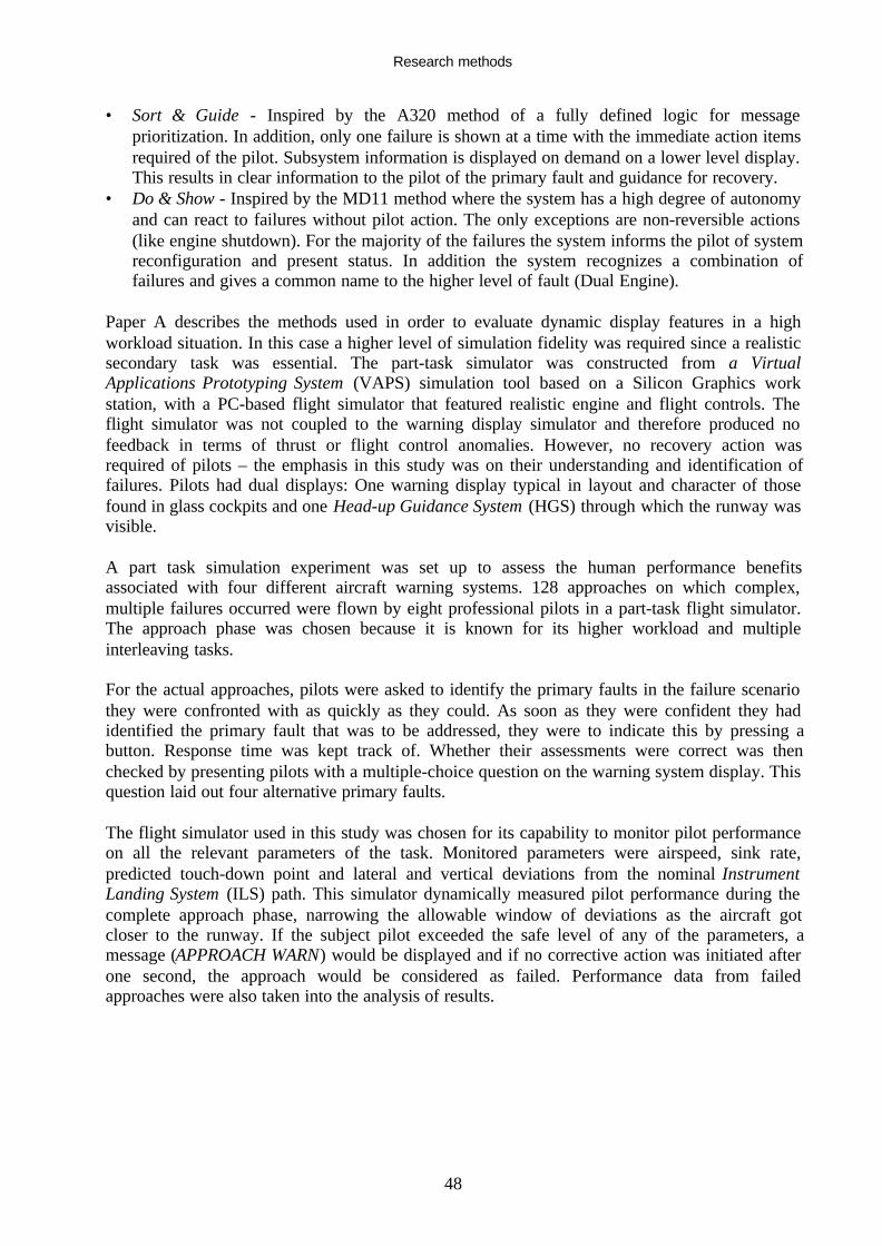
Research methods
48
• Sort & Guide - Inspired by the A320 method of a fully defined logic for messageprioritization. In addition, only one failure is shown at a time with the immediate action itemsrequired of the pilot. Subsystem information is displayed on demand on a lower level display.This results in clear information to the pilot of the primary fault and guidance for recovery.
• Do & Show - Inspired by the MD11 method where the system has a high degree of autonomyand can react to failures without pilot action. The only exceptions are non-reversible actions(like engine shutdown). For the majority of the failures the system informs the pilot of systemreconfiguration and present status. In addition the system recognizes a combination offailures and gives a common name to the higher level of fault (Dual Engine).
Paper A describes the methods used in order to evaluate dynamic display features in a highworkload situation. In this case a higher level of simulation fidelity was required since a realisticsecondary task was essential. The part-task simulator was constructed from a VirtualApplications Prototyping System (VAPS) simulation tool based on a Silicon Graphics workstation, with a PC-based flight simulator that featured realistic engine and flight controls. Theflight simulator was not coupled to the warning display simulator and therefore produced nofeedback in terms of thrust or flight control anomalies. However, no recovery action wasrequired of pilots – the emphasis in this study was on their understanding and identification offailures. Pilots had dual displays: One warning display typical in layout and character of thosefound in glass cockpits and one Head-up Guidance System (HGS) through which the runway wasvisible.
A part task simulation experiment was set up to assess the human performance benefitsassociated with four different aircraft warning systems. 128 approaches on which complex,multiple failures occurred were flown by eight professional pilots in a part-task flight simulator.The approach phase was chosen because it is known for its higher workload and multipleinterleaving tasks.
For the actual approaches, pilots were asked to identify the primary faults in the failure scenariothey were confronted with as quickly as they could. As soon as they were confident they hadidentified the primary fault that was to be addressed, they were to indicate this by pressing abutton. Response time was kept track of. Whether their assessments were correct was thenchecked by presenting pilots with a multiple-choice question on the warning system display. Thisquestion laid out four alternative primary faults.
The flight simulator used in this study was chosen for its capability to monitor pilot performanceon all the relevant parameters of the task. Monitored parameters were airspeed, sink rate,predicted touch-down point and lateral and vertical deviations from the nominal InstrumentLanding System (ILS) path. This simulator dynamically measured pilot performance during thecomplete approach phase, narrowing the allowable window of deviations as the aircraft gotcloser to the runway. If the subject pilot exceeded the safe level of any of the parameters, amessage (APPROACH WARN) would be displayed and if no corrective action was initiated afterone second, the approach would be considered as failed. Performance data from failedapproaches were also taken into the analysis of results.

Results
49
7 ResultsThe results presented in this chapter include empirical ones attained through formal experimentsdescribed in the appended papers, the limited experiments described in the Research methodschapter and process results from other relevant work by the author.
7.1 Capitals or Mixed font – Recall abilityThe ability to recall and understand the text messages was compared by projecting a typicalcombination of warning messages for a short duration using each method at a time. The datacollected by comparing the level of correct recall showed a clear trend. The mixed font (figure13) showed a much higher level of correct recall compared with the capitals only messages. Therecall results were checked for the intent of the messages and not the precise wording. Each ofthe participating decision makers attending the meeting was able to see the immediate personaland group recall performance and this resulted in the management acceptance of the featurealready at the software definition stages. No further data collection or formal statistical analysiswas performed.
L Elevator FAILRudder Limiter INOPAPU Generator FAILL Eng Sensor A FAILAFT Cargo FireDet FAILEss Bus 1 Volt LOFuel Balance Pump ONL Hyd Stby Pump FAULT
Figure 13: Mixed font showed superior content recall
7.2 Error rates when reading textThree methods of message syntax were designed into typical warning messages representing fivedifferent failure cases normally encountered. The data collected from 11 subjects, each exposedto 15 cases was analyzed for errors using electronic multiple choice questions.The following results were attained after 165 runs:

Results
50
Display method: Error rate: • Speech oriented (Do728/S2000 inspired) 4% errors (2 of 55 runs)• System oriented (A320 inspired) 8% errors (4 of 55 runs)• Index oriented (B777 inspired) 17% errors (9 of 55 runs)
These results show a clear decrease in error rates when using the speech-oriented method (Do-728, S-2000) of writing a warning message. The message grammar is based on normal spokenEnglish grammar rather than a system or maintenance oriented syntax. The results are based on alimited number of subjects and do not take into account the total design philosophy of eachaircraft type. Nevertheless, based on equal conditions and using a limited simulation, the resultsdo show a significant difference in pilot error rates.
When comparing several methods of text syntax to display warning messages, the results showedthat the solution using a natural speech word hierarchy (write as you speak), produced the leasterrors in recall. In this case the goal was to determine the best of three more or less equivalenttechnical solutions and to aid management in accepting a Human Factors subjectiverecommendation by using empirical results. Based on this experiment the guidelines for a newaircraft cockpit display philosophy was modified and implemented (Fairchild Dornier, 2001)
7.3 Recovery errors from a banked flight conditionIn the case of the ADI and its effect on the recovery from a banked condition, the tool used was apart-task simulator in the form of a laptop PC (Singer & Dekker, 2002 – Paper D). Figure 14shows the simple part-task simulation results; the average roll-reversal error rates and standarderror of the mean (T bars) for all three ADIs. Due to one subject making a non-typical largenumber of errors on one type of ADI, the data set was truncated and the results reevaluated.When truncating the data set by removing both the highest and lowest scores from each ADI, therelative results were unchanged. While recovery on the military and general aviation ADI wasroughly similar, immediately obvious was the inferior performance on the commercial ADI. Rollreversal errors on the commercial ADI were almost five times more frequent than on the othertwo ADIs (figure 14). Since there were no significant differences in response times across thethree different ADI presentations, pilots do not appear to engage in a speed-accuracy trade-off.Although in this case the conventional design is too well established for change, this resulthighlights the need for recovery aids to assist the pilot in identifying the correct bank angle.

Results
51
Figure 14: Roll recovery error rates when using three types of ADI
The experimental set-up in the study of course lacked the kinds of natural cues that may bepresent in real roll reversal. Yet in instrument flying (whether military, commercial or generalaviation) visual cues from the instruments are deemed the most reliable, and pilots areconsistently taught to distrust other sources. In fact, it is the ADI, including the sky pointer, thatis the primary instrument for attitude control and recovery. The presence of natural cues canoften aggravate spatial disorientation, rather than alleviating it, and probably did not aid inpreventing several loss-of-control accidents (HF-HWG, 2001; CAA, 1998; FOCA, 2001).
Recovery error rates
0
2
4
6
8
10
12
14
16
18
Gen Com Mil
ADI type
%
avg recovery errorrates - %
truncated avgrecovery error rates -%

Results
52
7.4 Pilot performance during multiple system failuresA highly dynamic part-task simulation experiment generated empirical results on pilotperformance when using different warning systems. In existing warning systems available fromcommercial aircraft manufacturers, four levels of fault management support can be distinguished(Singer & Dekker, 2002 – Paper A). These characterizations are not one-to-one relationships towhat the manufacturers offer, but rather inspired by how these systems work.
Figure 15 shows the mean response times and error rates on the four different warning systemsevaluated in this study. Using Sort & Guide, pilots were quickest to acknowledge that they hadunderstood the failure scenario and recognized the primary fault, and indeed made no erroneousassessments of the failure scenario. Following closely in mean response time, Do & Show alsoproduced a zero error rate. Show All led to the longest response times and highest error rate.
Figure 15: RT and error-rates identifying primary cause using four display philosophies
The results attained from the multiple system failure perception show a clear error rate increasefor the non-prioritizing systems (Show All) compared with the systems using high levels ofprioritization and guidance (Do & Show, Sort & guide).
In the evaluation of pilot performance during multiple failures (Singer & Dekker, 2000 - PaperA), statistically significant results showed improved pilot performance with the system givingmore prioritization and guidance. This may explain the tendency of several display philosophies(ones that provide the crew with all the data and allow the crew to analyze) to cause mentaloverload and inability to cope with the information as derived from accident data (Mårtensson,1995). Despite the risk of providing the pilot with highly filtered and processed data, it seemsthat the limited capability of the pilot to process all the information favors the smarterpresentation philosophies.
0
2
4
6
8
10
12
Show All Sort & Show Sort & Guide Do & Show0%
5%
10%
15%
20%
25%
30%
35%
40%
Response Time (SEC) Error rate (%)

Results
53
Overall results are consistent with expectations of how various warning systems would aidhumans in their dynamic fault management. Human performance gains become visible as soon asthe warning system itself manages various failures in some way before presenting them. There isan increment in these performance gains, based on the nature and depth to which the warningsystem supports the failure management task. Modest performance benefits are associated with asystem that sorts the failures and shows them selectively, but some errors in identifying theprimary fault still occur. Performance benefits really accrue with a system that sorts through thefailures, shows them selectively and guides the pilot in what to do next. In this study, pilots werequickest to identify the primary fault in the failure scenario with such a system, and made noerrors in assessing what it was. Similarly, a warning system that itself contains or counteractsmany of the failures and shows mainly what is left to the pilot, scores low response times andzero error rates in identifying the primary fault.
7.5 Measuring end-to-end performance and workloadIn the certification process of the HUD as the means of pilot-in-the-loop approach aid (Singer &Dekker, 2001 - Paper B) a detailed description of using a full flight simulator for certificationwas shown. The total performance of the aircraft, including pilot precision, errors and variationwere all measured and analyzed statistically in all predicted environmental and operationalconditions. The participants were the typical end-users with minimal training on the new HUDsystem and the testing was done in high workload and fatigue conditions. Since this specificcertification of the SAAB 2000 HUD in 1995 (Singer, 1999), many other HUD systems havebeen approved in a similar way with impressive airline safety record (FSF, 1997; HF-HWG,2001). When evaluating the future certification of integrated systems like the FMS, the methodused in the HUD certifications is proposed as an effective tool for validating other complexsystems with pilot performance issues. Navigation systems can be measured as to their ability tofollow the intended path, including system performance and crew interface. It is important tokeep in mind that when measuring performance parameters not to be tempted to just measure theeasy ones.
7.6 The DIVA projectThe author of this thesis participated as a test pilot and designer in a recent project that addressedseveral of the deficiencies and solutions found in Human Factors research and attempted to findpractical solutions based on a structured methodology (Singer, 2001 – Paper C). This project canbe used as a good example of a new structure for a Human Centered and Performance Basedapproach to cockpit design. The DIVA (Design of Human/Machine and their validation inAeronautics) project (Nibbelke, et al., 2000) used the experience of the aviation industry andresearch institutes and addressed the issues of Controlled Flight Into Terrain (CFIT) displays andsystem failure presentation (including early predictions).
The project utilized a step-by-step approach making use of accepted management and cognitivetools. The method consisted of three phases:• The first phase was gathering the user requirements with the help of a management tool
called Quality Function Deployment (QFD). This tool was developed to fit the cockpitenvironment, and included a large matrix that converted customer requirements into lower levelengineering requirements. The tool also allowed for subjective ratings of importance and relativeimportance of the parameters (Nibbelke et al., 1998).

Results
54
• The second phase included the review of relevant accident data in order to construct realisticscenarios in which the new design feature could be validated. The scenarios were determinedbased on expert inputs including test pilots. The scenarios were built around simulation toolsthat allowed exposure of a non-expert crew to time and flight phase limited scenarios. Objectivemeasuring equipment, such as eye tracking devices and data recording equipment, werecombined with subjective evaluations. Uninvolved experts including test pilots and testengineers performed a structured design review. This was in order to get a second opinion of theexperiment layout and correlation with the initial customer requirements. The review alsoconsidered whether known human factor guidelines were implemented in the design.
• The last phase was the actual evaluation performed by airline pilots of varying experience andrecording objective and subjective data. The simulations were performed with and without thenew design features or with different levels of automation of the features. This data was thencompared with the initial management tool and correlation was evaluated.
The DIVA project implemented the new approach of systematically using customer requirementcriteria, accident data, to base modern technical solutions. The design was determined by expertssuch as test pilots and validated in simulators using line pilots.
Despite the improved approach used by this project, the time scale and simulation complexityencountered requires a simplification of the process in order to become usable for the process ofdesign and validation of a real aircraft project. In addition, the method has not been shown to besuperior to the classic method of good engineering practice since no parallel conventionalapproach was tested for comparison.
7.7 New Human Factors rules and guidance materialIn order to ensure common compliance documentation for all applicants and minimize thecompetitive issues, detailed certification rules and guidance material must be provided by therelevant regulatory agencies. The requirements for detail do not indicate a need for prescriptiveparagraphs. The requirements should be based on freedom of innovation but set strictrequirement to provide compliance with predefined performance levels. Several means ofcompliance should be provided including analysis, simulation or experiments with appropriatefail/pass criteria. Such material should include guidance on error risk quantification, objectiveperformance criteria, the use of simulation and the participating evaluators. In addition, guidanceon what credit can be expected for actual service experience without further testing must also bespecified.
One effective method of improving future designs is undoubtedly the improvement of the designcertification requirements and associated advisory material. For the Transport Category aircraftthis is mainly regulated by the FAR/JAR 25 (FAA, 1998) and several Advisory Circulars(AC/ACJ). As explained in the introduction, the Human Factors contribution to incidents andaccidents has become a major concern in recent year. In order to address the Human Factorsissues in the cockpit design phase, the Human Factors Harmonization Working Group (HF-HWG) was formed. The HF HWG was created in August 1999 per the tasking published in theFederal Register, July 22, 1999 (FAA, 1999). The members chosen to build the team werechosen for their expertise in the fields of design, certification, research or operation of modernlarge aircraft. The author of this thesis was selected for the team as an industry representativecontributing with experience as a test pilot involved in design evaluation and certification. Thetasking that was accepted by the group can be summarized as follows:

Results
55
• Review the relevant existing FAA/JAA 25 rules and regulatory material applicable to flightdeck design, to determine their adequacy to consistently address design-related flight crewperformance vulnerabilities and the prevention and management of flight crew errors.
• Based on this review, recommend the updating of existing rules and advisory material ordevelopment of new rules, new advisory materials and the associated implementation plan.
• As work progresses, identify implications for qualifications and operations to becommunicated to and addressed by other appropriate groups.
The following can describe the methods used by the working group to achieve the tasks (HF-HWG, 2001):
• The first approach consisted of a direct review of the regulatory material by using a carefullyconstructed list of Human Factors topics to examine each component of the rules andassociated advisory documents to determine if the topics were consistently addressed or not,and why.
• The second approach was experience based. It started from a collection of data describingeither human performance problems (e.g., accidents or incident reports, experience of airlinepilots or test pilots) or actual instances in which certification experts could not find regulatorymaterial with which to address an obvious Human Factors design issue. This approachenabled the group to find data driven evidence of deficiencies in the present regulations.
Starting from an integrated list of the deficiencies identified by both approaches, the groupused predefined criteria to derive recommendations for developing or updating relevantFAR/JAR 25 rules and advisory material. These criteria will evaluate the safety benefit aswell as the expected acceptance and efficiency of these recommendations and will indicatepriority of implementation. If needed, the group will also issue recommendations foradditional work that should be carried out on non-FAR/JAR 25 rules (operations, licensing,maintenance, etc.).
The review process performed 1999-2001 (HF-HWG, 2001) showed clearly the weakness of thestructure and philosophy of the present regulation framework. The regulations are based on olddesign solutions, are either very generic or difficult to show objective compliance with or specifyoutdated solutions. The index system is system based and does not fit the modern integratedcockpit where many systems are cross woven in function, logic and failure modes. The role ofcrew resource management has not been addressed in the design and the usability issues arementioned only in general. The main dilemma of the working group is how to turn the rules andregulations into a flexible but consistent tool that will also address future designs and fit with theoperational rules that address the cockpit and crew.
The method used to define the best criteria was based on the review of the literature and expertiseof the group members. The evaluation criteria are based on the expected safety improvementwhich will result from the modifications introduced by the HF-HWG, as well as the feasibility ofthe recommendations, based on technical issues, cost-effectiveness, and the expected level ofacceptance by both the regulatory authorities and industry. The prioritization of therecommendations was based on a weighed voting methodology used on previous programsaddressing safety initiatives by regulation. This process, which was modified as needed to fit the

Results
56
HF- HWG task, used expert judgment to evaluate recommendations against a set of rating scales,which were then combined partly through the use of a mathematical algorithm.
The final report of the group will consist of recommendations for changes in the designregulations and advisory material that will enable to set better criteria for the approval of thehuman machine interface in commercial aircraft cockpits (final report expected - June 2002).Since not all deficiencies have the same weight regarding potential causation of accidents, theemphasis will be set on such issues that the group has defined as most critical and where achange will have the largest effect.
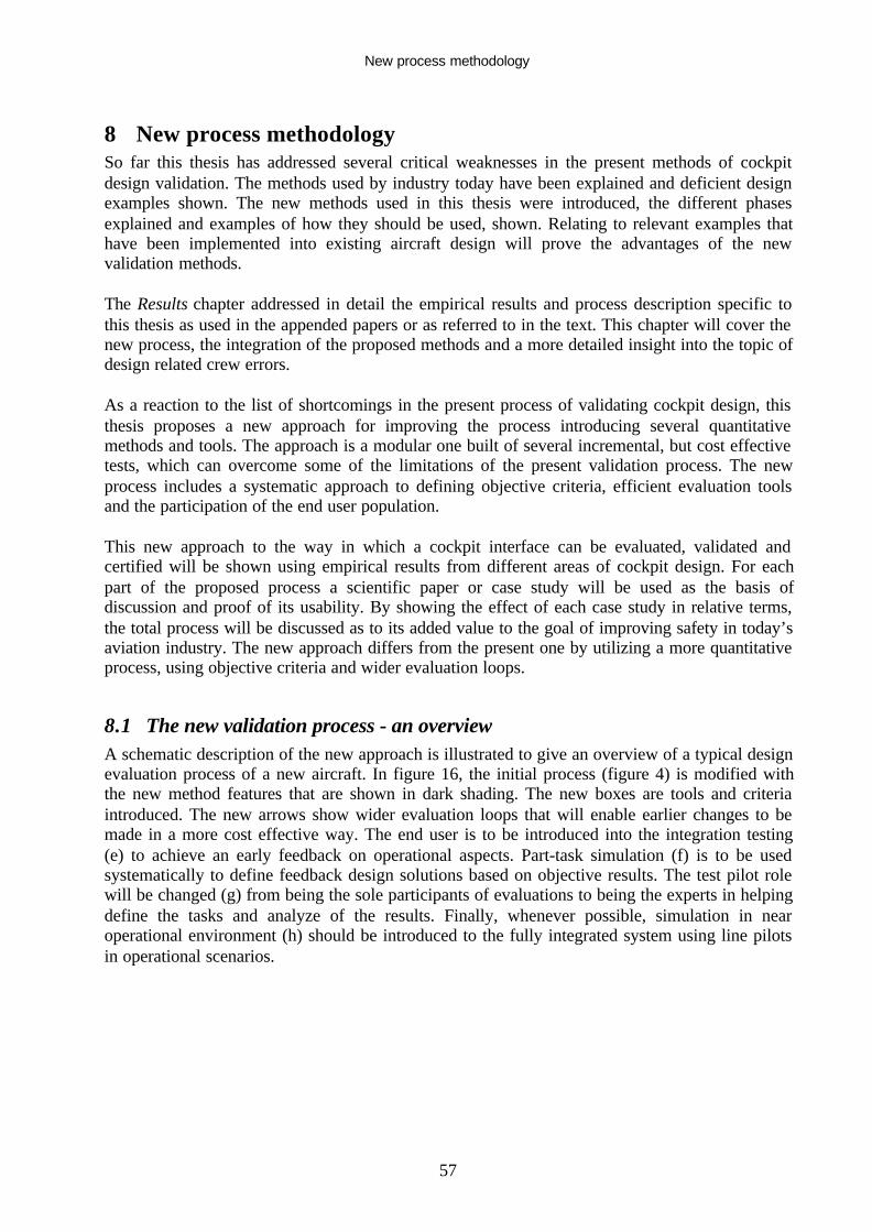
New process methodology
57
8 New process methodologySo far this thesis has addressed several critical weaknesses in the present methods of cockpitdesign validation. The methods used by industry today have been explained and deficient designexamples shown. The new methods used in this thesis were introduced, the different phasesexplained and examples of how they should be used, shown. Relating to relevant examples thathave been implemented into existing aircraft design will prove the advantages of the newvalidation methods.
The Results chapter addressed in detail the empirical results and process description specific tothis thesis as used in the appended papers or as referred to in the text. This chapter will cover thenew process, the integration of the proposed methods and a more detailed insight into the topic ofdesign related crew errors.
As a reaction to the list of shortcomings in the present process of validating cockpit design, thisthesis proposes a new approach for improving the process introducing several quantitativemethods and tools. The approach is a modular one built of several incremental, but cost effectivetests, which can overcome some of the limitations of the present validation process. The newprocess includes a systematic approach to defining objective criteria, efficient evaluation toolsand the participation of the end user population.
This new approach to the way in which a cockpit interface can be evaluated, validated andcertified will be shown using empirical results from different areas of cockpit design. For eachpart of the proposed process a scientific paper or case study will be used as the basis ofdiscussion and proof of its usability. By showing the effect of each case study in relative terms,the total process will be discussed as to its added value to the goal of improving safety in today’saviation industry. The new approach differs from the present one by utilizing a more quantitativeprocess, using objective criteria and wider evaluation loops.
8.1 The new validation process - an overviewA schematic description of the new approach is illustrated to give an overview of a typical designevaluation process of a new aircraft. In figure 16, the initial process (figure 4) is modified withthe new method features that are shown in dark shading. The new boxes are tools and criteriaintroduced. The new arrows show wider evaluation loops that will enable earlier changes to bemade in a more cost effective way. The end user is to be introduced into the integration testing(e) to achieve an early feedback on operational aspects. Part-task simulation (f) is to be usedsystematically to define feedback design solutions based on objective results. The test pilot rolewill be changed (g) from being the sole participants of evaluations to being the experts in helpingdefine the tasks and analyze of the results. Finally, whenever possible, simulation in nearoperational environment (h) should be introduced to the fully integrated system using line pilotsin operational scenarios.

New process methodology
58
Figure 16: New proposed design validation loops and tools (e, f, g & h)
The goal of these methods is to be able to identify design problems earlier in the design phase,thus minimizing the need for corrective measures such as training, procedures and operationallimitations. Needless to say that minimizing the error risks of critical functions in highlyautomated systems will drive us closer to our overall flight safety targets.
The new process methodology includes the following key components:• Developing new Human Factors rules and guidance material with means of compliance,• Introducing objective human performance criteria (effects of error),• Planning for consistent use of simulation tools,• Modification of the test pilot’s role in the process of cockpit design validation – using line
pilots for evaluations.
Together, these new process components will provide a structured and more effective approachthat can provide a validation process with a higher level of predictability.
Avionicssystem
Cockpitdesign
Cockpitavionicsrig
AircraftPrototype
FinalAircraftdesign
TrainingProceduresLimitations
FullSimulation
Part-taskSimulation
NEWTest pilotapproach
End userParticipation
NEW DetailedCertificationmateriale
gf h

New process methodology
59
8.2 Using part-task simulation tools for early, fact based, design decisionsIn order to reduce design risk and the need for late Band-Aid fixes, the review loops should bewidened and include the end user as early as possible. One method of achieving a more effectiveprocess is by using part-task simulation tools to test several design options for a specific task.This will be possible already at the early stages of design of the subsystems. This will also allowthe designer to validate the relevant philosophy assumptions. The task of the test pilots in thisphase will be to assist in defining design features and experiment layout, brief the end user pilotsand help evaluate the results.
The effective use of simple, easy to use, dynamic rapid prototyping tools for these evaluationswill reduce cost by addressing deficiencies earlier in the design process. Using the end user pilotwill ensure validation of the design assumptions at the subsystem level and reduce risks for thelater stages of design. These tools will be effective for assessing error modes and probable crewmistakes interpreting system feedback or operating the system controls. The initial Error HazardAnalysis (EHA), explained later, can then be substantiated systematically at the subsystem levelby introducing all possible (likely) errors to the simulated system and thus verify that the effect isas predicted by the initial safety assessment. Part-task simulations at a very crude level (PC slideshows) could be used as a tool for achieving internal team agreement and aid selection betweenseveral display options.
8.3 Full simulation for validating crew performance and workload When the design phase is complete and all the assumptions on its usability and error resistancemust be validated, the full simulation in near operational environment should be used. The toolwould usually be an engineering simulator with full functionality of all cockpit systems and agood environmental model. Specific scenarios should be run with minimum trained line crewswhile confronting them with normal and abnormal situations. The end result and performance areevaluated and compared with the minimum requirements set in advance (safe landing,navigation, flight path maintenance, communication levels, etc.) This method of validation combines compliance with airworthiness and operational requirementsand was used on the SAAB 2000 Head Up Display (HUD) certification program (Singer, 1999;Singer & Dekker, 2000 - Paper B). It is proposed here as a method for testing and validatingother integrated systems such as the FMS by using similar criteria measurements. This methodensures that the typical operator, and not only the test pilot population, is represented. The pointis not only to indicate how the behavior of human-machine systems should be measured, but alsowhat is measured (Stager, 1993). It enables the evaluator to collect objective performance anderror rate data and evaluate corrective procedures or design issues in order to rectify unacceptableresults. In the certification process of the HUD as the means of pilot-in-the-loop approach aid (Singer &Dekker, 2001 - Paper B) a detailed description of using a full flight simulator for certificationwas shown. The total performance of the aircraft, including pilot precision, errors and variationwere all measured and analyzed statistically in all predicted environmental and operationalconditions. This method was used to certify the HUD on several aircraft and later on maturedinto the regulatory circular AC 120-28D (FAA, 1997). The participants in this certificationprocess were the typical end-users with minimal training and the testing was done in highworkload and fatigue conditions.

New process methodology
60
In order to use the simulation to the full extent and retrieve subjective and objective data todetermine crew workload, a special comment card was found to be essential. Such a tool wasdeveloped by test pilots and engineers at Fairchild Dornier (figure 17) and used in developmenttests of novel features such as an active Electronic Checklist (ECL) incorporated into the cockpitcontrols and interface. The assumption was that the user is not familiar with workload definition,rating criteria or the certification details. The form allows the line pilot evaluator to giveworkload ratings based on simple statements and yet allow the engineer to correlate the answerswith existing design requirements. In addition, the form makes the pass/fail criteria visible to all.It was formulated as an effort to give a simple tool that addressed all of the new Human Factorsrequirements set by the JAA (JAA, 2001) and yet limits the effort and time required for theevaluation.
This method of evaluating end-to-end performance of minimum trained crews is presently beingimplemented on a new aircraft project (Do728). Following interim guidance material, the novelfeatures are evaluated as to their workload and error rate contribution in the context of theoperational cockpit use.

New process methodology
61
Figure 17: A partial simplified workload assessment tool for line pilot participation
ECL operation + Hyd 1 FailAirplane (Sim)TestConfiguration:Mission CREW Airspeed Altitude FD Mode LG/Hilift MEL item Aircraft
B LH/SIG VNAV 1000-2000ft LNAV /VNAV
UP/UP none TAC 73
EnvironmentalConditions:Temperature Ice Cross Wind Turbulence Visibility TRAFFIC
ISA No 10 kts LIGHT IMC High density
TheTasks:• perform take-off roll according to AFM and follow SID to MUC
• A failure will be introduced after takeoff – Address it using ECL safe altitude• Maintain full navigation compliance, communication and standard aviate• Land at nearest airport – within 20 min (if possible)
RatingscaleWorkload Rating Demands on the pilot to achieve the task
SAT Easy to use:• ample spare capacity,• predictable,• clear consistent feedback
ADQ Difficult to use:• little spare capacity,• limited trial and error needed• confusing feedback,
EXC Usability in question:• no spare capacity,• tasks not fully achieved,• feedback misleading,
Pilot Task Assessment (use: SAT, ADQ orEXC): The sub-Task Rating
identification, verification, decision-making SAT
Checklist selection and flow until complete ADQ
Reversion to secondary tasks using CCD or MCDU (aviate, communicate, navigate) SAT
Returning to task if interrupted ADQ
Compliance with deferred items and limitations SAT
Aiding decision making (limitations, urgency, economy)
Keeping the flying pilot in the informed ADQ
TotalRatings:Task completed? Highest Workload Allowed workload Errors encountered Video recorded
YES ADQ ADQ REV / Non-REV
Objective measurements (ifapplicable):Task completed? Time to complete Allowed time Aviate
exceedanceNavigate exceedance
YES 3 min 20 min Stall warning Missed ILS arming
Remarks(YES/NO):Is color coding and icons consistent YES
Was the new feature consistent with the rest of the cockpit controls YES

New process methodology
62
8.4 Quantifying human error riskWhen evaluating pure system failures, the certification process is based on a probability analysisthat looks into the relation between the effect of a failure and the probability of its occurrence(figure 18). This process is driven for single and multiple failures and is strictly regulated by thedesign requirements (FAR/JAR 25.1309) stating that the effect of a failure must be inverselyproportional to the probability of its occurrence (FAA, 1998). The most probable failures mustnot have more than a minor effect on safety margins; workload and passenger comfort while theimprobable ones may have hazardous effects. Failure combinations that have a catastrophiceffect may not be more than extremely improbable (probability of occurrence of less than orequal to 10-9).
Effect onAeroplane
No effect onoperationalcapabilities orsafety
Slight reduction infunctionalcapabilities orsafety margins
Significantreduction infunctionalcapabilities orsafety margins
Large reduction infunctionalcapabilities orsafety margins
Normally with hullloss
Effect onOccupantsexcluding FlightCrew
Inconvenience Physicaldiscomfort
Physical distress,possibly includinginjuries
Serious or fatalinjury to a smallnumber ofpassengers orcabin crew
Multiple fatalities
Effect on FlightCrew
No effect on flightcrew
Slight increase inworkload
Physicaldiscomfort or asignificant increasein workload
Physical distress orexcessiveworkload impairsability to performtasks
Fatalities orincapacitation
AllowableQualitativeProbability
No ProbabilityRequirement <---Probable---> <---Remote--->
Extremely<------------------->Remote
Extremely<-------------------> Improbable
AllowableQuantitativeProbability:
AverageProbability perFlight Hour onthe Order of:
No ProbabilityRequirement
<------------------->
< 10-3
Note 1
<------------------->
< 10-5
<------------------->
< 10-7 < 10-9
Classification ofFailureConditions
No Safety Effect <------Minor------> <------Major------> <--Hazardous--> Catastrophic
Note 1: A numerical probability range is provided here as a reference. The applicant is not required to perform aquantitative analysis, nor substantiate by such an analysis, that this numerical criteria has been met for Minor FailureConditions. Current transport category airplane products are regarded as meeting this standard simply by usingcurrent commonly-accepted industry practice.
Figure 18: The basis for system failure analysis in FAR/JAR AC(J) 25.1309
This process however does not take into account crew errors, whether in isolation or combinedwith system failures. The only reference is the general statements in paragraph 25.1309(c) and inthe regulation as to prevent errors when addressing system controls in paragraph 25.777. So farthe regulations and guidance material have not been changed to address this issue in a structured
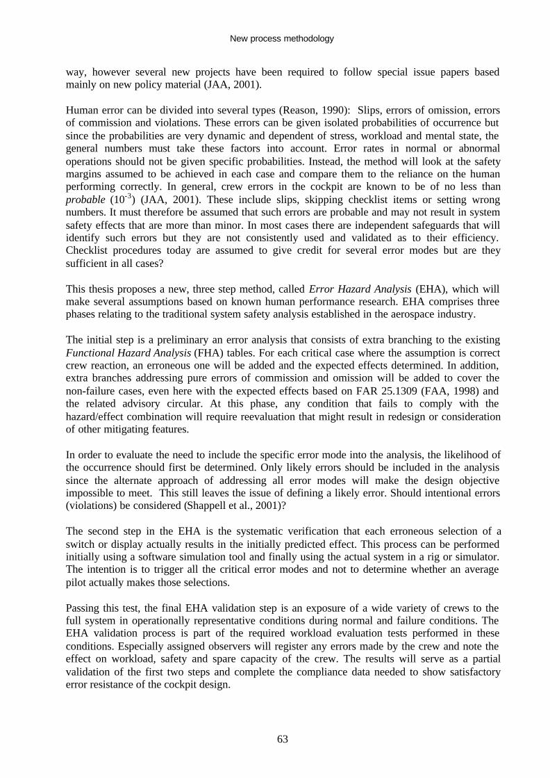
New process methodology
63
way, however several new projects have been required to follow special issue papers basedmainly on new policy material (JAA, 2001).
Human error can be divided into several types (Reason, 1990): Slips, errors of omission, errorsof commission and violations. These errors can be given isolated probabilities of occurrence butsince the probabilities are very dynamic and dependent of stress, workload and mental state, thegeneral numbers must take these factors into account. Error rates in normal or abnormaloperations should not be given specific probabilities. Instead, the method will look at the safetymargins assumed to be achieved in each case and compare them to the reliance on the humanperforming correctly. In general, crew errors in the cockpit are known to be of no less thanprobable (10-3) (JAA, 2001). These include slips, skipping checklist items or setting wrongnumbers. It must therefore be assumed that such errors are probable and may not result in systemsafety effects that are more than minor. In most cases there are independent safeguards that willidentify such errors but they are not consistently used and validated as to their efficiency.Checklist procedures today are assumed to give credit for several error modes but are theysufficient in all cases?
This thesis proposes a new, three step method, called Error Hazard Analysis (EHA), which willmake several assumptions based on known human performance research. EHA comprises threephases relating to the traditional system safety analysis established in the aerospace industry.
The initial step is a preliminary an error analysis that consists of extra branching to the existingFunctional Hazard Analysis (FHA) tables. For each critical case where the assumption is correctcrew reaction, an erroneous one will be added and the expected effects determined. In addition,extra branches addressing pure errors of commission and omission will be added to cover thenon-failure cases, even here with the expected effects based on FAR 25.1309 (FAA, 1998) andthe related advisory circular. At this phase, any condition that fails to comply with thehazard/effect combination will require reevaluation that might result in redesign or considerationof other mitigating features.
In order to evaluate the need to include the specific error mode into the analysis, the likelihood ofthe occurrence should first be determined. Only likely errors should be included in the analysissince the alternate approach of addressing all error modes will make the design objectiveimpossible to meet. This still leaves the issue of defining a likely error. Should intentional errors(violations) be considered (Shappell et al., 2001)?
The second step in the EHA is the systematic verification that each erroneous selection of aswitch or display actually results in the initially predicted effect. This process can be performedinitially using a software simulation tool and finally using the actual system in a rig or simulator.The intention is to trigger all the critical error modes and not to determine whether an averagepilot actually makes those selections.
Passing this test, the final EHA validation step is an exposure of a wide variety of crews to thefull system in operationally representative conditions during normal and failure conditions. TheEHA validation process is part of the required workload evaluation tests performed in theseconditions. Especially assigned observers will register any errors made by the crew and note theeffect on workload, safety and spare capacity of the crew. The results will serve as a partialvalidation of the first two steps and complete the compliance data needed to show satisfactoryerror resistance of the cockpit design.

New process methodology
64
Full task simulation should be used to measure crew performance and validate safety goals in thefinal step of the EHA. By using simulators rather than actual flight-testing, the full operationalenvironment and population of pilots can be investigated without risk. Point checks must still beflight tested in order to validate the simulator and system behavior. Test pilot expertise will beutilized to set up the interface tasks, scenarios and flight conditions. In addition, any flight testvalidation tasks should be planned and executed by test teams. The participants in the evaluationruns should be operators with minimum or typical training and experience of the new system. Byusing approved workload assessment tools and measuring relevant objective task performance,the final design can be shown to meet the end-to-end specifications set for the design. Inaddition, any errors actually made by the crew can be identified and evaluated as for theirpotential risk.
The proposed new method of addressing human error is by accepting certain general probabilitiesto human error and introducing these error modes into existing system safety analysis toolsalready in use. By expanding the existing System Safety Assessment (SSA) methodology andincluding errors as events combined with system failures, the exposure level that relies on humanbehavior is shown. A clearer explanation would be that of a basic tolerance to error would bedefined assuming the error risk will not be less than probable. This means that pure likely errorsof commission or omission (like forgetting a checklist item) may not result in more than minoreffects. For failure cases the methodology uses a similar approach as to effects of system failures(FAR 25.1309). The added effect due to error (following a failure) may not be more thanprobable for likely related errors. If the failure effect is major then an error in addition may notresult in more than a hazardous effect in the most critical condition.
If unable to meet these levels the error risk may be mitigated using one of the following features:• Technical resistance (inhibit thrust-reverser in flight) – can give credit for three effect levels
(pending equivalent system reliability).• Warning + reversible action (not setting correct altimeter settings) – can give credit for two
effect levels (assuming the initial action does not result in immediate loss of aircraft).• Warning only – (disconnecting an AP on a low visibility approach) – can give credit for one
effect level.• Crew procedure – well trained (approach briefing) – can give credit for one effect level.
By attaching the general error rates for each error mode the designer of a system will be able toapply the correct level of defense (warnings, inhibitions or procedures) to achieve the requiredlevel of criticality. For example, forgetting to lower the landing gear prior to landing, thoughprobable (10-3) might lead to a catastrophic effect (10-9). In order to show compliance thedesigner can take credit for an independent warning systems (10-3) and a checklist crosscheckprocedure (10-3) together meeting the design criteria level of (10-9). Including only one of themitigation features will not bridge the tolerance gap of two effect levels (10-6). And thus fail toshow compliance.
8.5 Modifying the role of the test pilotThe traditional role of the test pilot has always been the evaluator of new design features. Testpilots were trained to be observant, and knew how to use the complex rating scales. The new roleof the test pilot should be used more as a Subject Matter Expert (SME) involved in the planningof the tests, evaluating the test conditions and aiding in analyzing the test results. This does notreduce the need for test pilots in their traditional role of performing the demanding flight testprocedures (FAA, 2000) when developing new aircraft. When dealing with the approval of

New process methodology
65
complex system interfaces, pilots other than test pilots should be used as the test subjects. Thetest pilot will be involved in the philosophy of the design, checking consistency and determiningrelevant flying tasks in all flight conditions and unusual situations. The evaluation runs shouldinclude performance and error rate, exposing a wide population of the end user to measurementsin the most realistic scenarios. If the results require, the test pilot will be involved in modifyingthe design or the procedures and recommending training requirements in order to meet theperformance criteria during reruns.
In a book addressing cockpit display test and evaluation methods (Newman & Greeley, 2001) theauthors summarize by coming to similar conclusions, that test pilots should direct the tests, notperform the evaluations. In addition, they give an extra confirmation to the recommendations ofthis thesis by stating the need for objective performance criteria for testing rather thanrequirements for standardization.
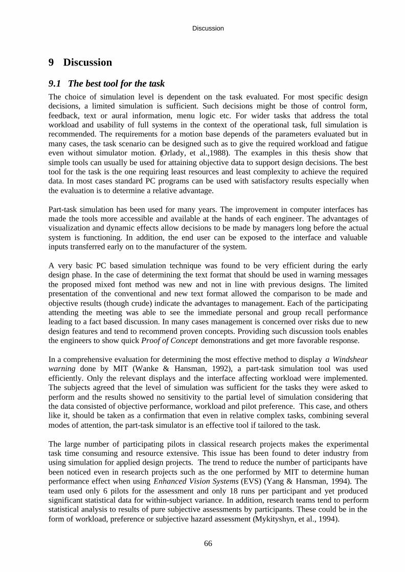
Discussion
66
9 Discussion
9.1 The best tool for the taskThe choice of simulation level is dependent on the task evaluated. For most specific designdecisions, a limited simulation is sufficient. Such decisions might be those of control form,feedback, text or aural information, menu logic etc. For wider tasks that address the totalworkload and usability of full systems in the context of the operational task, full simulation isrecommended. The requirements for a motion base depends of the parameters evaluated but inmany cases, the task scenario can be designed such as to give the required workload and fatigueeven without simulator motion. (Orlady, et al.,1988). The examples in this thesis show thatsimple tools can usually be used for attaining objective data to support design decisions. The besttool for the task is the one requiring least resources and least complexity to achieve the requireddata. In most cases standard PC programs can be used with satisfactory results especially whenthe evaluation is to determine a relative advantage.
Part-task simulation has been used for many years. The improvement in computer interfaces hasmade the tools more accessible and available at the hands of each engineer. The advantages ofvisualization and dynamic effects allow decisions to be made by managers long before the actualsystem is functioning. In addition, the end user can be exposed to the interface and valuableinputs transferred early on to the manufacturer of the system.
A very basic PC based simulation technique was found to be very efficient during the earlydesign phase. In the case of determining the text format that should be used in warning messagesthe proposed mixed font method was new and not in line with previous designs. The limitedpresentation of the conventional and new text format allowed the comparison to be made andobjective results (though crude) indicate the advantages to management. Each of the participatingattending the meeting was able to see the immediate personal and group recall performanceleading to a fact based discussion. In many cases management is concerned over risks due to newdesign features and tend to recommend proven concepts. Providing such discussion tools enablesthe engineers to show quick Proof of Concept demonstrations and get more favorable response.
In a comprehensive evaluation for determining the most effective method to display a Windshearwarning done by MIT (Wanke & Hansman, 1992), a part-task simulation tool was usedefficiently. Only the relevant displays and the interface affecting workload were implemented.The subjects agreed that the level of simulation was sufficient for the tasks they were asked toperform and the results showed no sensitivity to the partial level of simulation considering thatthe data consisted of objective performance, workload and pilot preference. This case, and otherslike it, should be taken as a confirmation that even in relative complex tasks, combining severalmodes of attention, the part-task simulator is an effective tool if tailored to the task.
The large number of participating pilots in classical research projects makes the experimentaltask time consuming and resource extensive. This issue has been found to deter industry fromusing simulation for applied design projects. The trend to reduce the number of participants havebeen noticed even in research projects such as the one performed by MIT to determine humanperformance effect when using Enhanced Vision Systems (EVS) (Yang & Hansman, 1994). Theteam used only 6 pilots for the assessment and only 18 runs per participant and yet producedsignificant statistical data for within-subject variance. In addition, research teams tend to performstatistical analysis to results of pure subjective assessments by participants. These could be in theform of workload, preference or subjective hazard assessment (Mykityshyn, et al., 1994).

Discussion
67
The limitations of a static, part-task simulation are clear. The lack of motion cues, the dynamicsof the displays and the immediate feedback to control inputs are only several issues that must beconsidered aircraft (Singer & Dekker, 2002 - Paper D). However, the experiment in Paper D didisolate a parameter that showed a significant increase in recovery errors under certain conditionssimulated. Such results could trigger further investigation of the conventions used in commercialaircraft ADIs for example.
For the final validation of complex new systems, even an engineering simulator (non-motion)may be used as long as all relevant system interfaces are available and a realistic environmentobtained. Finally, high fidelity engineering or training simulator could be used for attaining fullor partial credit as a validating tool for system failures and crew error modes needed forcertification.
9.2 The need for statistical significanceSeveral known researchers in the field have recently questioned the strict statistical methods usedin experimental psychology. Wickens in a keynote speech (Wickens, 1997b) called it “Thetyranny of the 0.05” referring to the fixed probability term significant used to show whenrejecting the Null Hypothesis. The use of experiment results that are not necessarily significantstatistically is discussed also in another paper (Wickens, 1997a). The author states that forshowing relative performance results for an industrial product, the full statistical validationmethod might not be valuable. Since the time and resources it requires might be prohibitive, asimple partial simulation might be used for engineering guidance or management discussions ofthe best way ahead.
In a more detailed paper, (Loftus, 1997) the deficiencies of the classic significance testingmethod are explained and instead the use of simple plots of the raw data and the confidenceintervals proposed.
These proposed simplified analysis tools will probably be more easily accepted by industry andwill not hide the true story of the raw data. In the Do728 display feature discussions, text displayand message grammatical structures were determined based on the faster method of analysis thatexcludes the statistical validation phase.
9.3 The way ahead with Human Factors certification requirementsThe introduction of detailed certification requirements and guidelines will allow the reviewprocess to determine whether the design meets the certification requirements, reduce the finalrisk and ensure common rules for all manufacturers. Defining objective criteria will result in amore systematic process, repeatable evaluations results and reduced scope for discussions. Theserequirements should include, the so-far often neglected, issue of crew errors. The criteria will bevalid for all new cockpits and thus result in a common minimum-standard levels for allmanufacturers. Detailed requirements by no means indicate prescriptive rules but rathermeasurable fail/pass criteria and the acceptable test method attaining the results.
The HF-HWG has almost completed its task and will submit recommendations for changes in theregulations and guidance material for Human Factors related design issues in the middle of 2002(HF-HWG, 2001). The author has been an active member of the working group and helped in thereview and recommendation process. The recommendations aim at giving more specific criteria

Discussion
68
for meeting an acceptable design by testing it rather than by setting prescriptive rules. Therecommendations take into account the operational aspects, rules and regulations that are notgoverned by FAR/JAR 25. Each recommendation will be rated as to its cost effectiveness interms of reducing accidents complexity and cost. Future features not yet implemented are alsotaken into account by forming the recommendation as not to be technology oriented but ratherhuman performance oriented. In parallel, several other regulatory initiatives have also addressedthe Human Factors issue and are used as policy papers and guidance (JAA, 2001; HF-HWG,2001; SPLASHER, 2001) until the process of changing the rules will be complete.
Some examples of the new HF-HWG proposed changes to the regulations relevant to this thesis(Singer, 2001 - Paper C) are listed below. These features were prioritized from a list of hundredsof deficiencies identified in order to assure that the following safety issues will be addressed first:
• Autopilot moding and feedback – (also addressed by another working group),• Defining alerting features,• Defining pilot skill,• Means of compliance for showing error avoidance,• Means of compliance for showing acceptable crew workload.
It has been the common agreement of most of the organizations involved in aircraft design,approval and operation that this aspect of design must be improved in order to reduce theabsolute number of accidents and incidents of global commercial aviation (FAA, 1996).Furthermore, the new rules and guidance will provide common grounds for competingmanufacturers as how to optimize the design feature without unnecessary cost and complexity. Itwill give management predictions for the adequacy of the design early in the design phase andlimit cases of failed design solutions identified late in the process. The working group will aim itsrecommendations at the issues posing highest risk to flight safety in the foreseeable future. Theintent is to make recommendations that will provide more precise guidance in how to test andshow compliance and not be prescriptive in nature.
These changes will not only have an effect on the design of the next generation of aircraftcockpits but many of the recommendations will hopefully be implemented also in the operationalmaterial that will change the approach to Human Factors validation and approval in the nearfuture.
9.4 Objective criteria for measuring human performanceObjective criteria have been used extensively by research institutions for attaining repeatable andacceptable results. These methods have hardly been used by the aircraft industry when evaluatingthe integration of the user and with new system interfaces. The reason for avoiding such methodshave probably been due to the extended time and effort required for attaining such data, the largenumber of participants required and the lack of requirements to use such a method. In all otherareas of design, testing and attaining objective performance results is the basis for any systemapproval.
As soon as the regulations and advisories will be updated to reflect such criteria it will not onlybe good engineering but also a requirement to use performance-based evaluations. Initialplanning and development of tools and knowledge for evaluating such data will requireinvestment but the new methods will have a predicted improvement (and hopefully also actual

Discussion
69
benefit) in safety. The advantage of such testing is that it can be rerun in the future with modifiedprocedures or features and the relative effect of the modification made visible.
9.5 Giving human error probability numbersThere seems to be a basic reluctance to assigning probability numbers to human error. The mainreasons being that these numbers vary as a function of workload, individual operator andoperating environment. This is true, but the same fact can also be stated when addressing systemcomponents. Even those numbers may vary if operating in severe conditions or dependant onproduction tolerances. And yet we have accepted average reliability numbers for all our safetyanalysis documentation even though they are also sensitive to operational environment.
Design solutions that mitigate errors can be made at several levels. System feedback can be usedby giving an indication to the correct controls (red lamps in the fire-handles), sounding a warningwhen a wrong setting is attempted (flap selection at an excessive speed) or system inhibition(gear retraction on the ground or thrust-reverser deployment in flight). Each solution has itstechnical drawbacks in the form of reliability, nuisance warnings and cost. A probabilisticapproach to crew error will allow a systematic approach that will be followed by all and applythe correct levels of defense for each condition depending on the predicted effects.
The three approaches to the error-problem are discussed in a paper that tries to assist designers insetting the correct error tolerance to each system (Courteney, 1998). The author gives some veryuseful suggestions and practical examples but still leaves the questions of which errors are likelyand when is mitigation necessary not fully answered. The author rejects the use of probabilitiesfor human error mainly because those numerical assumptions are probably not valid whentransferred from one situation to another. Instead the author proposes the inevitability view thatassumes that anything that can go wrong - will. This approach concentrates on the next step ofhow well the system can handle the error, or how error tolerant the system is. By setting simplerules for error tolerance, the author claims that an objective criteria is set without the use ofprobabilities. The author treats all errors as a certainty and then looks at the effect of thecombination of failure (if present) and the error. This approach might lead to unnecessary rigiddesign requirements when addressing unrelated unlikely errors. Examples could be a failure inone system and an erroneous response on a completely independent system, or the activation oflargely separated controls in the cockpit without any reason. If any abuse of cockpit control willneed to be taken into account the design features might become too cumbersome andcomplicated for normal use.
The approach of accepting probability over inevitability has been adopted by the FAA whenaddressing handling characteristics and performance following flight control failures in the newflight test guide advisory circular AC 25-7A (FAA, 2000). In this guide to failure effectevaluations, the FAA accepts a probabilistic approach to weather conditions severity as aninverse of the severity of the failure (probable failures require testing in severe weather whileimprobable failures may be tested in fair weather conditions). Weather, like humans, isunpredictable and yet a certain probability is accepted to allow a viable design method. It allowsall applicants to use the same conditions and design to the same level of safety based onprobabilistic assumptions as inaccurate as they might be.
In order to make an error resistant (or tolerant) design, a more systematic approach to crew erroris needed, whether for identifying errors in normal conditions or errors following a systemfailure. The only valid approach seems to be the future integration of the crew error probabilities
Discussion
70
into the basic system safety assessment. This evaluation will determine whether the effect of eachcombination requires a resistant design, whether a tolerant behavior will be sufficient or whethertraining and procedures are enough. In general there seems to be a similar attempt made from thecertification authorities, yet with different assumptions (Courteney, 1998; Courteney, 1999).
The use of probability numbers, as inexact as they may be, can be validated by research resultsand allow a structured approach to attaining a cost effective safety net in the design. The authoris not stating that precise numbers be given to each error mode of each control or level. Themethod is based on showing to what extent the design is exposed to errors, especially those withcritical consequences. The trend of accepting this approach has been evident in the new JAApolicy paper (JAA, 2001) but a quantitative approach must be taken to make the method effectivefor making design decisions.
Some mature system design solutions might have shown actual statistical human reliability muchhigher than the assumed probable figures (inadvertent selection of high-lift devices at highspeeds resulting in damage or aircraft loss on a specific large aircraft model) . In those cases thespecific design should be allowed under the “Equivalent safety” policy but any credit claimed fora new design must show that no changes have been made to the design from an interface aspectand that method of use is identical.
The resistance to accept probability numbers to human error is in disagreement with the praxis ofaccepting some error modes as feasible and some as not. Even at present, design solutions arebased on subjective evaluations of crew errors and their effect on safety. As shown earlier,present methods used for design are inconsistent regarding the effect of crew error and setssafeguards mainly based on past accidents.
Remains the typical claim of a manufacturer that a specific design feature has shown to be highlyreliable in actual service. There might be a significant exposure with reliable incident records.How could credit be given to such design even though it does not comply with the abovemethodology? Would credit be given when installed in a new aircraft? How much commonalityin cockpit layout and operations is needed for assuming similarity from a human error aspect?
The first step towards a quantified approach is to set Human Factors guidelines of specific meansof compliance when testing complex systems. This process is being undertaken by the HF-HWGwith reference to previous work done by the FAA and JAA (JAA, 2001). These guidelinesshould state acceptable levels of system exposure to errors in relation to the worst effect of suchan error. The means of compliance should include at least one method containing objectivecriteria for meeting the requirements. This still leaves the applicant with the option to select othermethods developed in-house and show equivalent safety. The author proposes that this methodbe based on a systematic review of all likely error modes with relation to the effect of such errorswhether in normal or failure conditions. The results will show whether additional mitigation isneeded or whether credit can be taken and procedures simplified to reduce crew workload.
9.6 Line pilots as the final evaluatorsThe test pilot is a highly trained pilot specializing in testing aircraft, using precision maneuversfor attaining data for the approval of the aircraft and its systems. Test pilots are experienced inhandling abnormal flight conditions, identifying unusual aircraft handling and communicatingwith the engineering community. They are a central function during all phases of aircraft design,testing and certification (Singer, 2001).

Discussion
71
The typical test pilot approaches the present evaluation task of determining the suitability of adesign mainly by relying on previous experience and using subjective evaluations. The test pilotis asked to make comments on error risks and the effect of such an error on flight safety withouthaving the full knowledge and tools to evaluate human error. Instead, the validation processshould be changed to using the test pilot in the design of the experiments and evaluations andimplement realistic scenarios. A variation of end user pilots with minimum training on the newsystem should be used for the operational validation process. The tools used, such as ratingscales, must be made usable by the end user and sufficient training in their use assured.
Test pilots however are not good subjects for testing the effect of system failures in normaloperational environment when the average pilot skill should be represented. Despite beingtrained to assume the minimum qualified user pilot, their high level of skill and knowledgeresults in higher than average performance especially when encountering unexpected problems inflight. This thesis has also shown several examples where despite test pilot techniques it was notpossible to detect hidden design flaws. The test pilot does not always have the airline mentalityof communicating and coordinating during flight. He is usually aware of the detailed systemdesign and philosophy and is trained to analyze system failures. The test pilot is usually moreproficient in handling a degraded aircraft or system and has much more experience in addressingnon-normal situation.
The present evaluation tools used in research projects are complex and if wrongly used, caneasily lead to bias. Rating scales, like the Cooper Harper or Bedford workload scales aredesigned for expert use and are intended for development decisions. They are usually found notto fit tests where the goal is only finding an acceptable level of safety of usability (not ranking ofseveral systems) for an existing system. Such evaluations are becoming more common whenshowing compliance with new cockpit features or systems (JAA, 2001). In such a scenario, linepilots should be given simple tools that will address the issue in question without unnecessarycomplexity.
Such an evaluation is consistent with increasingly common ecological approaches to assessinghuman-computer interaction (Rasmussen & Pejtersen, 1995). In these, the emphasis shifts fromproving that the system works at a single point in time, to assessing where and how it worksduring an extended episode of operational exposure. Such an approach to assessment is moresensitive to how the addition of new technology transforms human roles and work, and to howhumans in turn adapt the new device to make it work for them in their circumstances. All the above reasons point to the fact that a test pilot is not used in the most efficient way as aparticipant in Human Factors evaluations especially when the operational scenarios are tested.For those tests, also line pilots with minimal system training should be used in order to collectthe data. This does not exclude the need for the test pilot for designing the scenario, testing it andhelping in planning and analysis of the experiments.

Conclusions
72
10 ConclusionsThe new proposed process approaches the problem of cockpit design validation from severaldirections. Based on analysis of empirical results relevant to new cockpit features it shows howdesign features can be compared in a cost effective way and design decision made aided by theresults. In parallel the thesis proposes an improved validation process that includes widerevaluation loops, and a timely use of simulation at several levels. In order achieve better results,and based on past experience, the roles of the test pilot and line pilot are modified. Throughoutthe thesis, flight test and certification experience in industry and research theories are used tosubstantiate the statements and suggestions.
To summarize: The new validation process of cockpit design can provide more reliable andrepeatable results by implementing the following aspects:
10.1 Widening the feedback loops and evaluator groupsSeveral examples of early testing of design features showed statistically significantimprovements in operator perception and objective performance. Several of these features havebeen introduced into an existing aircraft design in progress. The use of line pilots as evaluatorshave shown stable results with a high level of acceptance of the final product in normal and non-normal situations.
Widening the feedback loops and including end users in the evaluator groups will improve endproduct usability and safety levels while maintaining reasonable project costs and schedule. Atpresent, the design review feedback loops are initially localized to each vendor or systemdesigner and the end user is kept out of the loop until the product enters service (or very close toit). By widening the feedback loop forward early in the process and by assuring that the final userrequirements are met as intended, the usability level will be increased. Evaluation groups shouldbe asked to participate in early reviews of the upstream components and not only the local designissues (Nibbelke et al., 1998). By doing so, the design intentions will be carried out moreprecisely from the vendor through the system integrator to the final user.
10.2 Early use of part-task simulationThe use of part-task simulation has allowed several designs to be changed with low cost penaltiesbased on simple experiments. Using the PC based tools early in the design have allowed earlyevaluations of novel design features and allowed the engineers to substantiate their rationale. Theimprovements of the warning systems of the SAAB 2000, the HUD implementation for lowvisibility approaches and the warning message design of the Do728 are several examplessubstantiating the proposal and showing partial validity of the process.
Whenever used, part-task simulations have helped the designers and final evaluators get a betterunderstanding of display dynamics and feedback features while change was still possible. Whenintroducing novel features such as Cursor Control Devices (CCD) for operating systems duringall flight conditions, these simulation tools become even more essential for early designdecisions.

Conclusions
73
10.3 Developing detailed certification materialThe introduction of detailed Human Factors certification requirements and guidelines are in thephase of recommendations to the American and European administrations. The author has beenan active member of the HF-HWG since 1999. The working group was tasked to finddeficiencies and make recommendations for revised or new HF design related material. The HF-HWG is formulating the final report where more detail and performance criteria will enable themanufacturers to evaluate each new design against clear, non-prescriptive paragraphs andguidelines. A final report will be presented to the FAA in mid 2002 according to the AviationRulemaking Advisory Committee (ARAC) process. This report will be in turn published asregulations and advisories for the design of large commercial aircraft. Several regulations will bemade into operational guidelines that will take effect even earlier and for existing aircraft. Theinternational agreement and professional recommendations made by this team show the need forsuch detailed requirements in the future and provide a partial substantiation of the thesishypothesis.
In the mean time, the FAA and JAA have produced interim documents (policy, specialconditions and certification review items) that have aided the manufacturers in defining the scopeand methods for Human Factors certification of novel features (JAA, 2001; SPLASHER, 2001)
10.4 Modifying the task of test pilotsIn several cases described in this thesis, the test pilot’s role has been different than the traditionalone. Instead of being the evaluator, the validation process changed to using the test pilot forassisting in the designing of the experiments and evaluations. The test pilot helps determinerealistic scenarios while the typical line pilot, with minimum system training, is used for theevaluation and validation process. The results of such evaluations have shown so far a smoothentry into service and a safe track record for the HUD low visibility landing system (HF-HWG,2001). Recent acceptance of the new approach to test pilot tasking by test pilots, authorities anddesigners shows a positive trend in the aviation industry in the direction proposed in this thesis.
Finally, the new cockpit design validation process has been shown to assist in achieving a morereliable and systematic means of predicting cockpit usability and safety. It is based onincremental improvements and not one magic solution. The empirical examples described in thisthesis are only spot checks for several design issues and are only the first step of applying thenew method. International acceptance is needed and time will tell its success.

References
74
References
AIA/AECMA Project Report, (1998). Propulsion System Malfunction plus Inappropriate CrewResponse (PSM+ICR), volume 1.
Billings, C.E., (1997). Aviation automation – the search for a human-centered approach.Lawrence Erlbaum Associates, Publishers, Mahwah, New Jersey.
CAA, (1998). CAP 681, Global Accident Review, Dated March 1998, Gatwick, England.CAA, (2000). P-NPA 25-310, Issue 1 Human Centered Design Requirements, Dated April 2000,
Gatwick, England.Cook & Campbell, (1989). Quasi-Experimentation, Houghton Mifflin Company, Boston, pp. 37-
91.Courteney, H.Y., (1998). User Error: Practical Ways to Protect Your System, Proceedings of the
International Council of Systems Engineers Conference on People, Teams and Systems,Vancouver, July 1998.
Courteney, H.Y., (1999). Human factors of automation: The regulator’s challenge. In S. W. A.Dekker & E. Hollnagel (Eds.), Coping with computers in the cockpit, pp. 109-130. Aldershot,UK: Ashgate.
FAA, (1987). FAA Advisory Circular 25-11, Electronic Displays in Transport CategoryAirplanes. Washington DC: Federal Aviation Administration.
FAA, (1996). Human factors study team report on the interface between flight crews and modernflight deck systems. Washington DC: Federal Aviation Administration.
FAA, (1997). Advisory Circular 120-28D, Criteria for approval of CAT III weather minimatakeoff, landing and rollout, Draft 13, Washington DC: Federal Aviation Administration.
FAA, (1998). Code of Federal Regulations (CFR 14), Parts 1-59 & 60-139, Draft 13,Washington, DC: Federal Aviation Administration.
FAA, (1999). Federal Register, 1999, HF-HWG July 22, 1999,http://www.researchintegrations.com/hf-hwg/fed-reg-tasking-index.htm
FAA, (2000), Advisory Circular 25-7A, Flight Test Guide, Washington DC: Federal AviationAdministration.
Fairchild Dornier, (2001). ATA 31 - 728JET Family Flight Deck Philosophies, Issue 7A, ES2(internal document), Fairchild Dornier GmbH, Wessling, Germany.
FOCA, (2001). Saab 340 accident report (Crossair Flug CRX 498 vom 10. Januar, 2000 beiNassenwil), 2001, http://www.bazl.ch/
FSF, (1997). Flight Safety Foundation, Official Foundation Position Paper, FSF 50th AnnualConference, 3-6 November, Washington, USA.
Gilson, R., Deaton, J. & Mouloua, M., (1996). Coping With Complex Alarms, Ergonomics inDesign, (October, 1996).
HF-HWG (2001). Interim report,:www.researchintegrations.com/hf-hwg/index.htmHopkin, V. D. ,(1993). Verification and validation: Concepts, issues and applications. In: J. A.
Wise, V. D. Hopkin, & P. Stager, (Eds.): Verification and validation of complex systems:Human factors issues, pp. 9-34. NATO ASI series F, Vol. 110. Berlin: Springer-Verlag.
ICIS - Integrated Crew Information System Evaluation Program, (1997). Avionitek report, Haifa,Israel.
ISO 9241, (1997-1998). Parts -11, -14, -15, -17, International Standard Ergonomic Requirementsfor office work with visual display terminals (VDTs).
JAA, (2001). Human Factors aspects of Flight Deck Design –Issue 2, JAA Interim PolicyINT/POL/25/14, http://www.srg.caa.co.uk/documents/intpol.pdf.
Kuchar, J., & Hansman, J., (1993). Part Time Simulator Evaluations of Advanced TerrainDisplays, SAE Technical Paper Series 932570, pp. 119-127.
References
75
Loftus, G. R., (1997). Psychology will be a Much Better Science When We change the Way WeAnalyze Data, Current Directions in Psychological Science 6 (1), pp. 22-35.
Mårtensson, L., & Singer, G., (1998). Warning Systems in Commercial Aircraft - an Analysis ofExisting Systems. Royal Inst. of Technology, Dept of Industrial Economics andManagement, TRITA-IEO-1998:01, ISSN 1100-7982, ISRN KTH/IEO/R-98-SE.
Mårtensson, L., (1995). The aircraft crash at Gottröra: Experience of cockpit crew, Theinternational Journal of Aviation Psychology, 5(3), 305-326. Lawrence Erlbaum Ass. Inc.
Mykityshyn, M., Kuchar, J., & Hansman, J., (1994). Experimental Study of Electronically BasedInstrument Approach Plates, The International Journal of Aviation Psychology vol. 4 (no. 2)pp. 141-166.
Newman, R. & Greeley, K., (2001). Cockpit Display: Test and Evaluation, Ashgate PublishingLimited, UK: Aldershot.
Newman, T., (1997). Safety –The global challenge, CAA policy paper, The Proceedings of theFlight Safety Foundation's 9th annual European Aviation Safety Seminar, Amsterdam.
Nibbelke, R., et al., (1998). The use of Quality Function Deployment to analyze Human FactorsRequirements in Civil Flight Deck Design, in Engineering Psychology and CognitiveErgonomics, vol. 3 pp. 85-92.
Nibbelke, R., et al., (2000). Where do we go from here? Navigation decision aiding in the case ofsub-system failure, in Engineering Psychology and Cognitive Ergonomics, vol. 5 pp. 135-142.
Noyes, J., Starr, A. & Frankish, C., (1996). User involvement in the early stages of thedevelopment of aircraft warning systems, Behavior & Information Technology, vol. 15 (no.2) pp. 67-75.
Noyes, J., Starr, A. & Rankin, J., (1996). Designing Warning Systems: Role of Pilot Expertise,BA publications, FSG 18.
Noyes, J., Starr, A., Frankish, C, & Rankin, J., (1995). Aircraft warning systems: Application ofmodel-based reasoning techniques, Ergonomics vol. 38 (no. 11) pp. 2432-2445.
Orlady, H., Hennessey, R. & Murphy, M., (1988). Using full-mission simulation for humanfactors research in air transport operations, Technical Memorandum 88330, Scientific andTechnical Information division, NASA, California.
Ovenden, C. & Frankish C., (1993). MBRAWSAC: Model Based Reasoning Approach toWarning Systems for Aircraft Cockpits, JFIT Conference, Keele University.
Ovenden, C., (1993), Model Based Reasoning applied to Cockpit Warning, Smith IndustriesResearch and Product Technology, Cheltenham, UK.
Paries, J., (1994). Some Inadequacies of the Current Human Factors Certification Process ofAdvanced Aircraft Technologies. In J. A. Wise, V. D. Hopkin, & D. J. Garland, (Eds.)Human Factors of Advanced Aviation Technologies, pp. 301-306. Embry-RiddleAeronautical University, Daytona Beach, Florida USA. Publication in cooperation withEurocontrol.
Pritchett, A., (2001). Reviewing the role of cockpit systems, Human Factors and AerospaceSafety, vol.1 (nr. 1), pp. 5-38, UK: Ashgate Publishing.
Rasmussen J., & Pejtersen A. M., (1995). Virtual ecology of work. In J. Flach, P. Hancock, J.Caird, K. Vincente (Eds.), Global Perspectives on the Ecology of Human Machine SystemsVolume 1, pp. 121-156. Hillsdale, NJ: Erlbaum.
Reason, J., (1990). Human Error, New York: Cambridge University Press.Rignèr, J., & Dekker, S., (1999). Modern flight training – managing automation or learning to
fly?, in Dekker & Hollnagel Coping with Computers in the Cockpit, Ashgate, Hants, UK, pp.145 –151.
Roscoe, S. N., (1968). Airborne displays for flight and navigation, Human Factors, 10, 321-332.

References
76
Roscoe, S. N., (1975). Motion Relationships in aircraft attitude and guidance: A flightExperiment, Human Factors, 17, 374-387.
Roscoe, S. N., (1980). Display Motion Relationships (Chapter 7) in Aviation Psychology, IowaState University Press / Ames.
Sarter N. B., Woods D. D., Billings C.E., (1997). Automation Surprises: In, G. Salvendy (Ed.),Handbook of human factors/ergonomics. Mahwah, NJ: Erlbaum.
Shappell, S., & Weigmann, D., (2001). Reviewing the role of cockpit systems, Human Factorsand Aerospace Safety, vol. 1 (nr. 1), pp. 59-86, UK: Ashgate Publishing.
Singer, G., & Persson, U., (1996). Fly-by-Wire for the SAAB 2000 - Concept, Development, andTesting - 20th ICAS Congress proceedings - Sorrento, Italy.
Singer, G., (1992). The SAAB 2000 - Initial flight test status report - Society of ExperimentalTest Pilots (SETP) Conference proceedings - Beverly Hills, September 1992.
Singer, G., (1999). Filling the gaps in the human factors certification net. In S. W. A. Dekker &E. Hollnagel (Eds.), Coping with computers in the cockpit, pp. 87-108. Aldershot, UK:Ashgate.
Singer, G., (2000). Towards a safer cockpit - Improving cockpit interface through flight test.Licentiate thesis, Report 2000-8, Royal Institute of Technology, Stockholm, Sweden. ISSN0280-4646.
SPLASHER, (2001). Starting Point to Learn About Safety and Human Error Risks, Issue 1, Sept2001, http://www.hfstg.org
Stager, P., (1993). Validation in complex systems: Behavioral issues. In: J. A. Wise, V. D.Hopkin, & P. Stager, (Eds.): Verification and validation of complex systems: Human factorsissues, pp. 99-114. NATO ASI series F, Vol. 110. Berlin: Springer-Verlag.
Ulfvengren, P., Mårtensson, L. & Singer, G., (2001). Auditory and visual warnings in aircraft,preprints 8th IFAC Symposium on Analysis, Design and Evaluation of human-machinesystems, Kassel, Sept 18-20, 2001, pp. 59-63. VDI/VDE-Gesellschaft Mess- undAutomatisierungstechnik (GMA).
Wanke, C., & Hansman, J., (1992). Hazard Evaluation and Operational Cockpit Display ofGround Measured Windshear Data, Journal of Aircraft vol. 29 (no. 3) pp. 319-325.
Wickens, C., (1992). Engineering Psychology and Human Performance, (process Controlchapter), Harper Collins Publishers, Illinois, USA.
Wickens, C., (1997a). Attentional Issues in Head Up Displays. In D. Harris (Ed) EngineeringPsychology and Cognitive Ergonomics (vol. 1). pp. 3-22. Ashgate: Aldershot.
Wickens, C., (1997b). Statistical Testing in Engineering Psychology, American PsychologicalAssociation 1997, Annual meeting, USA.
Wilson & Corlett (Eds.), (1995). Evaluation of Human Work, Taylor & Francis, University ofNottingham, pp. 113-132, 245-279.
Wogalter, M., DeJoy, D. & Laughery, K. (Eds.), (1999). Warnings and risk communication –Chapters 3 & 4 - Methodological considerations for research on warnings, Taylor and FrancisInc. Philadelphia.
Woods, D. & Sarter, N., (1998). Learning from Automation Surprises and Going Sour Accidents,Institute for Ergonomics, Report ERGO-CSEL-98-02, prepared for NASA Ames, Calif.,USA.
Woods, D., (1995). The alarm problem and directed attention in dynamic fault management. InErgonomics, vol. 38 (no. 11), pp. 2371-2393.
Yang, L., & Hansman, J., (1994). A Human Performance Evaluation of Enhanced VisionSystems for Approach and Landing, SPIE Technical Conference – Image Sensing, Processingand Understanding for Control and Guidance of Aerospace Vehicles, Paper no. 2220-27,Orlando, Florida.