Embed Size (px)
Citation preview
Methods for Software Specification
Prof. Ing. Ivo Vondrak, CSc.Dept. of Computer Science
Technical University of [email protected]
http://vondrak.cs.vsb.cz
References Rumbaugh, James et al. Object-Oriented Modeling and Design, Prentice Hall Inc.
1991 Booch, Grady: Object-Oriented Analysis and Design, The Benjamin/Cummings
Publishing Company, Inc. 1994 Jacobson, I., Christerson, M., Jonsson, P., Overgaard, G.: Object Oriented
Software Engineering, A Use Case Driven Approach, Addison-Wesley, 1994 Gamma, E., Helm,R., Johnson,R., Vlissides,J. Design Patterns, Elements of
Reusable Object-Oriented Software, Addison-Wesley, 1994 Booch, G., Jacobson, I., Rumbaugh, J.: The Unified Modeling Language User
Guide, Addison Wesley Longman, Inc., 1999 Schmuller, J.: Teaching Yourself UML in 24 Hours, Sams, 1999 OMG Unified Modeling Language Specification, version 1.5, http://www.uml.org,
2003 Warmer, J., Kleppe, A.: The Object Constraint Language Second Edition, Getting
Your Models Ready for MDA, Addison-Wesley, 2003
Contents
Introduction UML Language Formal Methods of Specification Design Patterns
Definition of OOM Method is well-considered (sophisticated) system of doing
or arranging something. Architecture is the organizational structure and associated
behavior of a system. Object is an entity with a well-defined boundary and identity
that encapsulates state and behavior. An object is an instance of a class.
Object-oriented architecture is the structure of connected objects that define resulting behavior of the system through their communication (interactions).
Object-oriented method is sophisticated system of doing software based on object-oriented architecture.Object-oriented method is sophisticated system of doing software based on object-oriented architecture.
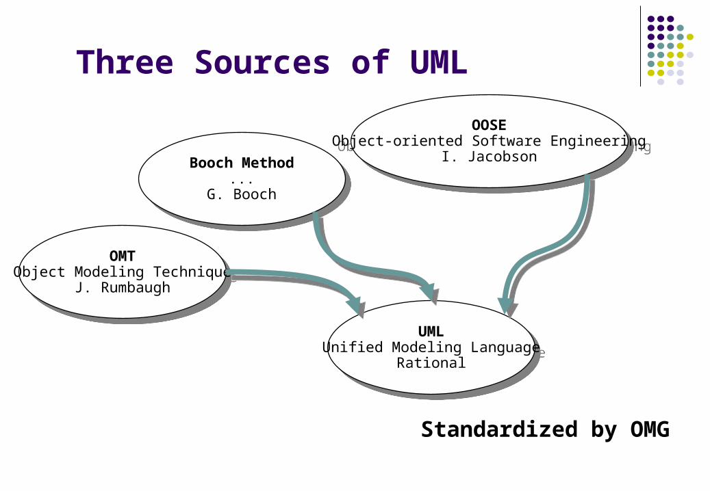
Three Sources of UML
OMTObject Modeling Technique
J. Rumbaugh
OMTObject Modeling Technique
J. Rumbaugh
Booch Method...
G. Booch
Booch Method...
G. Booch
OOSEObject-oriented Software Engineering
I. Jacobson
OOSEObject-oriented Software Engineering
I. Jacobson
UMLUnified Modeling Language
Rational
UMLUnified Modeling Language
Rational
Standardized by OMG
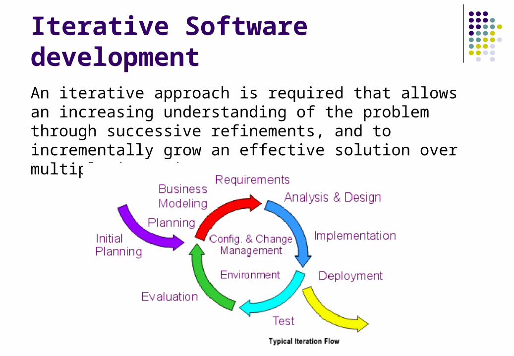
Iterative Software developmentAn iterative approach is required that allows an increasing understanding of the problem through successive refinements, and to incrementally grow an effective solution over multiple iterations.
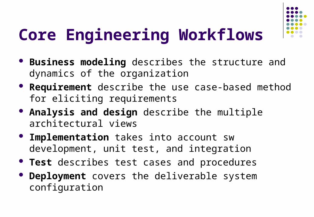
Core Engineering Workflows
Business modeling describes the structure and dynamics of the organization
Requirement describe the use case-based method for eliciting requirements
Analysis and design describe the multiple architectural views
Implementation takes into account sw development, unit test, and integration
Test describes test cases and procedures Deployment covers the deliverable system configuration
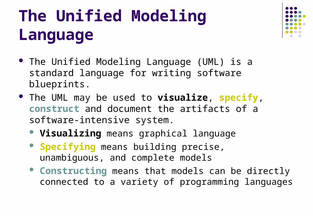
The Unified Modeling Language
The Unified Modeling Language (UML) is a standard language for writing software blueprints.
The UML may be used to visualize, specify, construct and document the artifacts of a software-intensive system. Visualizing means graphical language Specifying means building precise, unambiguous, and
complete models Constructing means that models can be directly connected
to a variety of programming languages
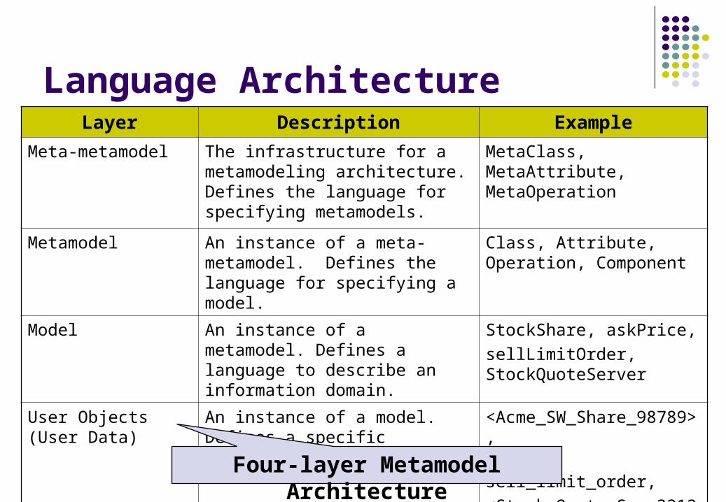
Language ArchitectureLayer Description Example
Meta-metamodel The infrastructure for a metamodeling architecture. Defines the language for specifying metamodels.
MetaClass, MetaAttribute, MetaOperation
Metamodel An instance of a meta-metamodel. Defines the language for specifying a model.
Class, Attribute, Operation, Component
Model An instance of a metamodel. Defines a language to describe an information domain.
StockShare, askPrice,
sellLimitOrder, StockQuoteServer
User Objects (User Data)
An instance of a model. Defines a specific information domain.
<Acme_SW_Share_98789>,
654.56, sell_limit_order,
<Stock_Quote_Svr_32123>
Four-layer Metamodel Architecture
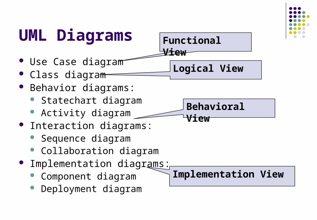
UML Diagrams Use Case diagram Class diagram Behavior diagrams:
Statechart diagram Activity diagram
Interaction diagrams: Sequence diagram Collaboration diagram
Implementation diagrams: Component diagram Deployment diagram
Functional View
Logical View
Behavioral View
Implementation View
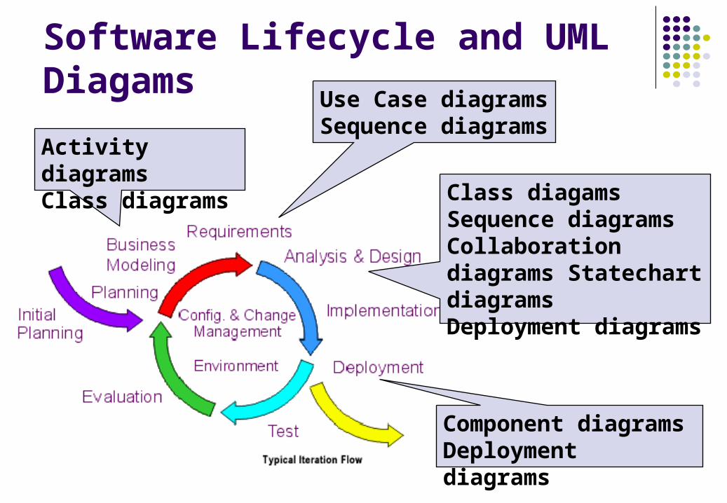
Software Lifecycle and UML Diagams
Activity diagramsClass diagrams
Use Case diagramsSequence diagrams
Class diagamsSequence diagramsCollaboration diagrams Statechart diagramsDeployment diagrams
Component diagramsDeployment diagrams
Exercises
What is the object-oriented methods about? What is the definition of the object-oriented method?
What diagrams are used to specify each workflow of the software development iteration?
What is the UML language architecture. Describe four-layer metamodel architecture!
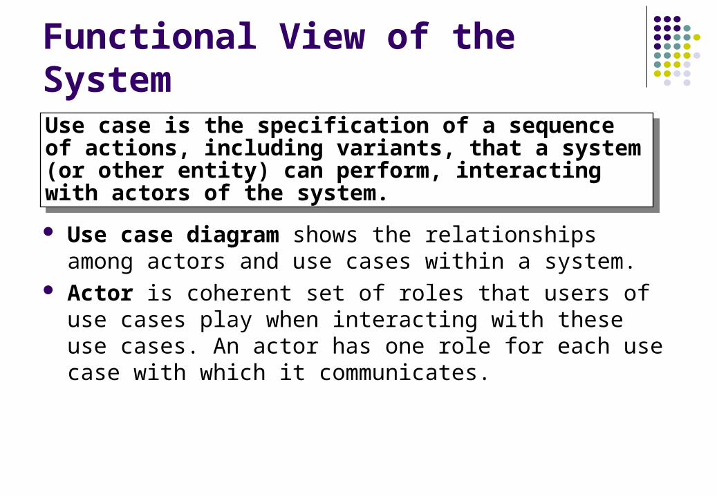
Functional View of the System
Use case diagram shows the relationships among actors and use cases within a system.
Actor is coherent set of roles that users of use cases play when interacting with these use cases. An actor has one role for each use case with which it communicates.
Use case is the specification of a sequence of actions, including variants, that a system (or other entity) can perform, interacting with actors of the system.
Use case is the specification of a sequence of actions, including variants, that a system (or other entity) can perform, interacting with actors of the system.
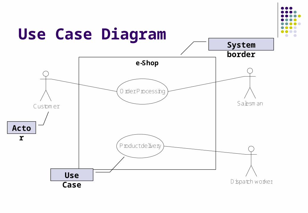
Use Case Diagram
e-Shop
Order Processing
Product delivery
Customer Salesman
Dispatch worker
Actor
Use Case
System border
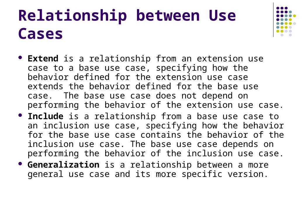
Relationship between Use Cases Extend is a relationship from an extension use case to a base
use case, specifying how the behavior defined for the extension use case extends the behavior defined for the base use case. The base use case does not depend on performing the behavior of the extension use case.
Include is a relationship from a base use case to an inclusion use case, specifying how the behavior for the base use case contains the behavior of the inclusion use case. The base use case depends on performing the behavior of the inclusion use case.
Generalization is a relationship between a more general use case and its more specific version.
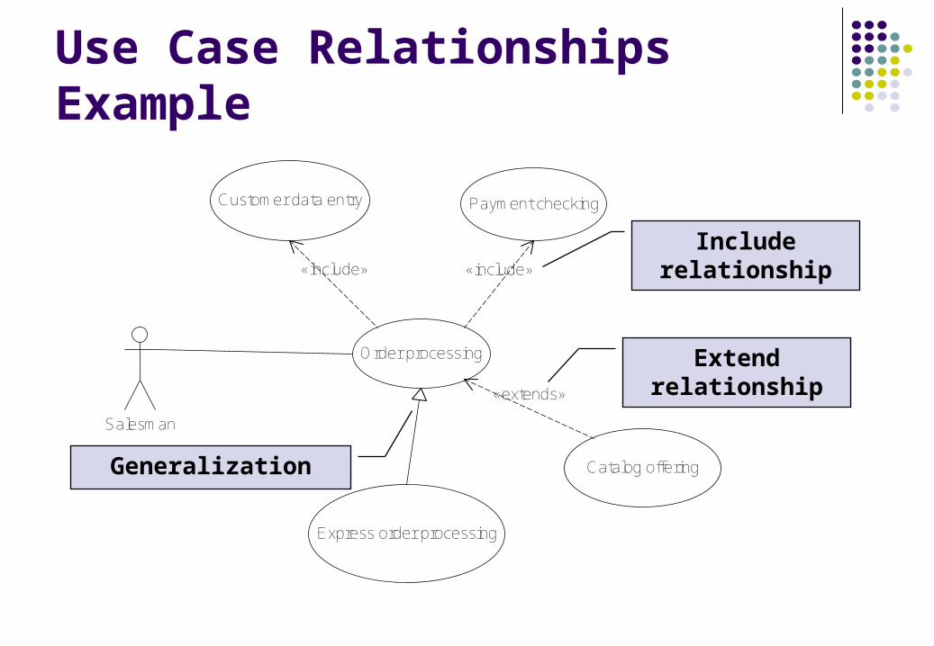
Use Case Relationships Example
Order processing
Payment checking
Catalog offering
Customer data entry
Express order processing
«include» «include»
«extends»
Salesman
Include relationship
Extend relationship
Generalization
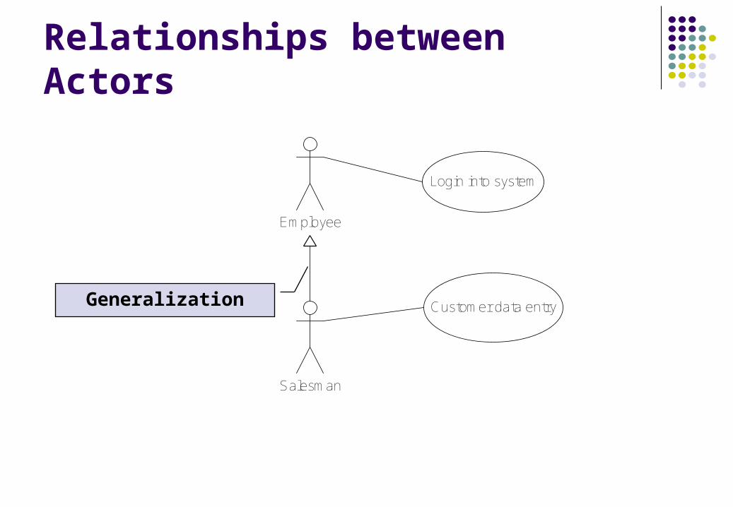
Relationships between Actors
Customer data entry
Salesman
Employee
Login into system
Generalization
Exercises
What entities are used by use case diagrams? List and describe all kind of relationships used by use
case diagram specification! Specify all use cases employed by the customer of
eShop!
Logical View of the System
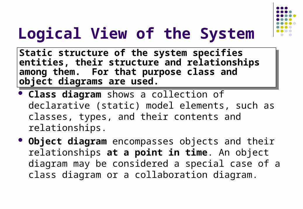
Class diagram shows a collection of declarative (static) model elements, such as classes, types, and their contents and relationships.
Object diagram encompasses objects and their relationships at a point in time. An object diagram may be considered a special case of a class diagram or a collaboration diagram.
Static structure of the system specifies entities, their structure and relationships among them. For that purpose class and object diagrams are used.
Static structure of the system specifies entities, their structure and relationships among them. For that purpose class and object diagrams are used.
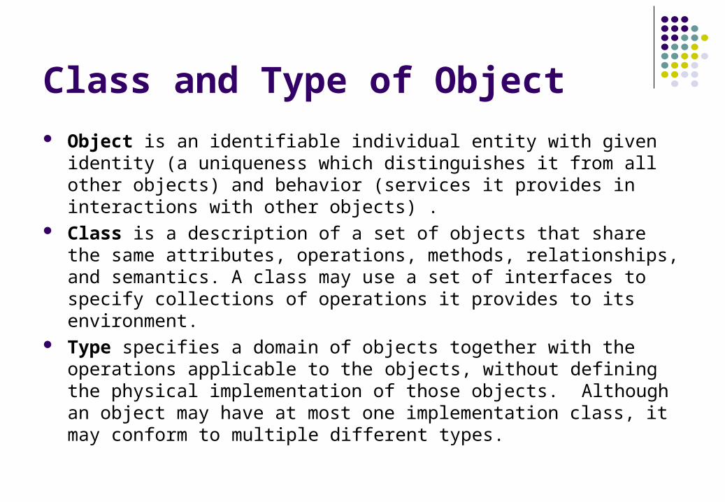
Class and Type of Object Object is an identifiable individual entity with given identity (a uniqueness
which distinguishes it from all other objects) and behavior (services it provides in interactions with other objects) .
Class is a description of a set of objects that share the same attributes, operations, methods, relationships, and semantics. A class may use a set of interfaces to specify collections of operations it provides to its environment.
Type specifies a domain of objects together with the operations applicable to the objects, without defining the physical implementation of those objects. Although an object may have at most one implementation class, it may conform to multiple different types.
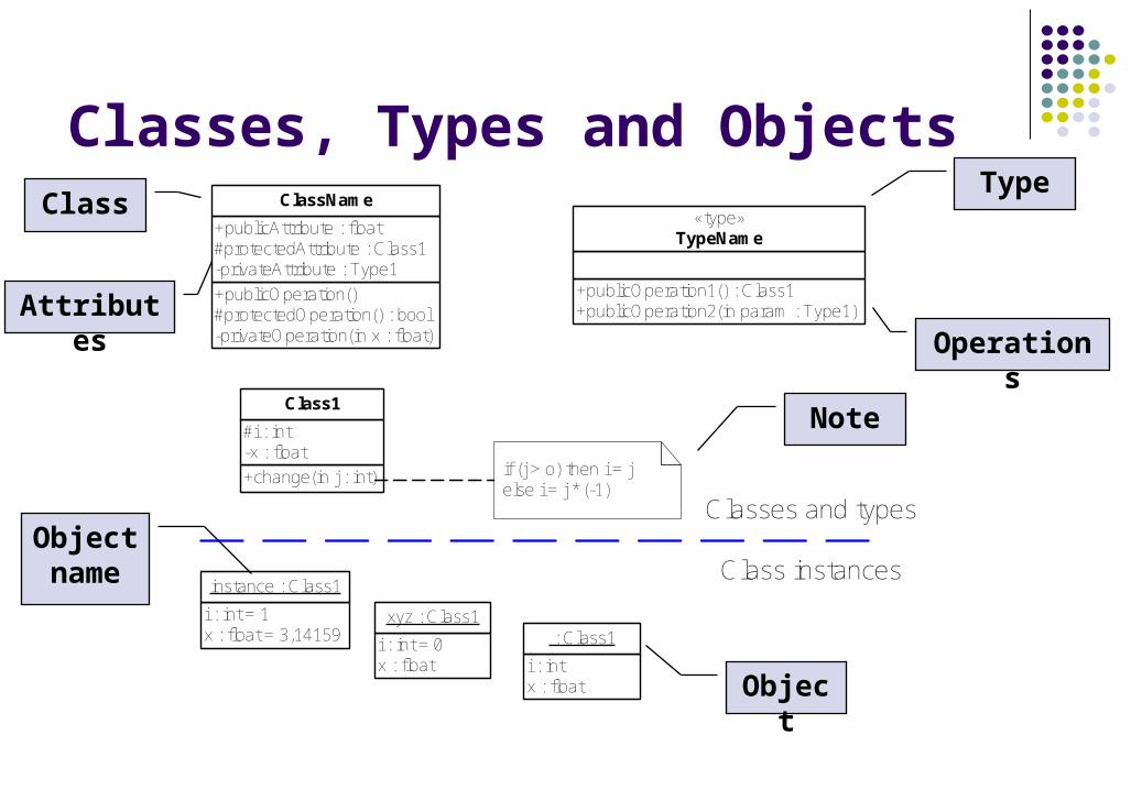
Classes, Types and Objects
+publicOperation()#protectedOperation() : bool-privateOperation(in x : float)
+publicAttribute : float#protectedAttribute : Class1-privateAttribute : Type1
ClassName
+publicOperation1() : Class1+publicOperation2(in param : Type1)
«type»TypeName
+change(in j : int)
#i : int-x : float
Class1
if (j > o) then i = jelse i = j * (-1)
i : int = 1x : float = 3,14159
instance : Class1
i : int = 0x : float
xyz : Class1
i : intx : float
: Class1
Classes and types
Class instances
ClassType
Object
Note
AttributesOperations
Object name
Implementation Class and Interface
Implementation class is said to realize a type if it provides all of the operations defined for the type with the same behavior as specified for the type's operations.
Interface is a named set of operations that characterize the behavior of an element.
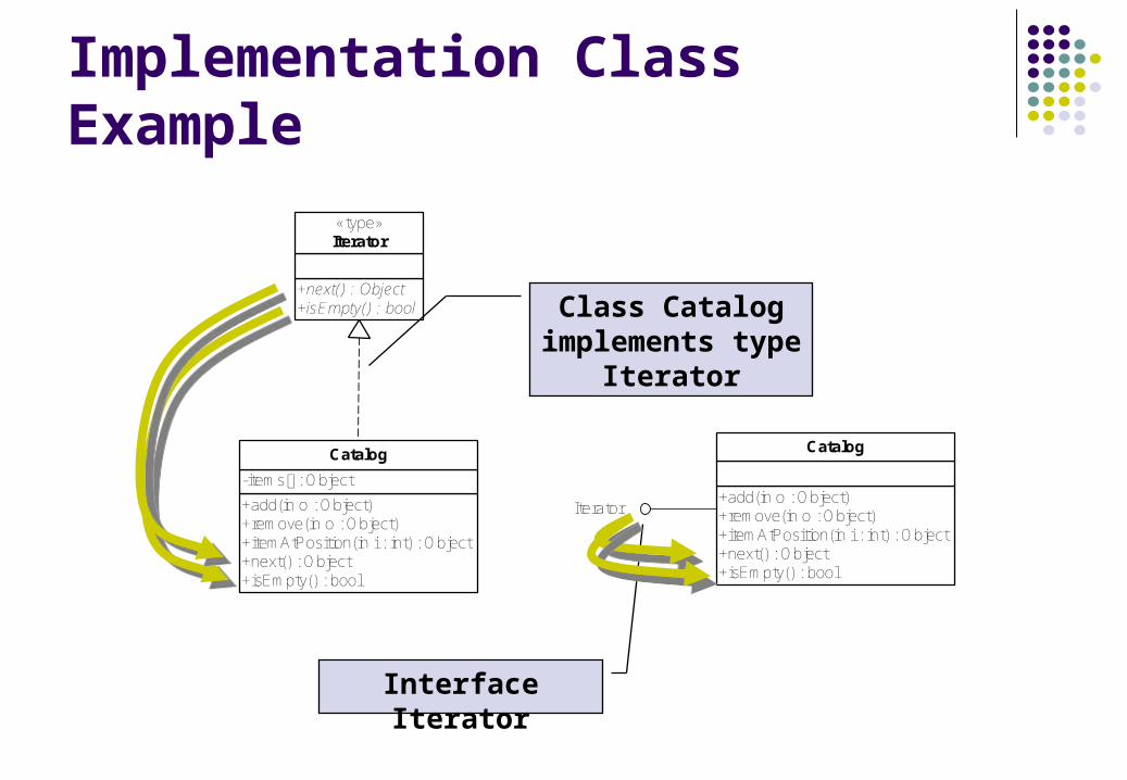
Implementation Class Example
+add(in o : Object)+remove(in o : Object)+itemAtPosition(in i : int) : Object+next() : Object+isEmpty() : bool
-items[] : Object
Catalog
+next() : Object+isEmpty() : bool
«type»Iterator
+add(in o : Object)+remove(in o : Object)+itemAtPosition(in i : int) : Object+next() : Object+isEmpty() : bool
Catalog
Iterator
Class Catalog implements type
Iterator
Interface Iterator
Relationships Among Objects and Classes Association describes a group of links with common
structure and common semantics (a Person works-for aCompany). An association a bi-directional connection between classes that describes a set of potential links in the same way that a class describes a set of potential objects.
Aggregation is the “part-whole” or “a-part-of” relationshipin which objects representing the components of somethingare associated with an object representing the entire assembly.
Dependency is a weaker form of relationship showing a relationship between a client and supplier.
Generalization is the taxonomic relationship between a more general element (the parent) and a more specific element (the child) that is fully consistent with the first element and that adds additional information.
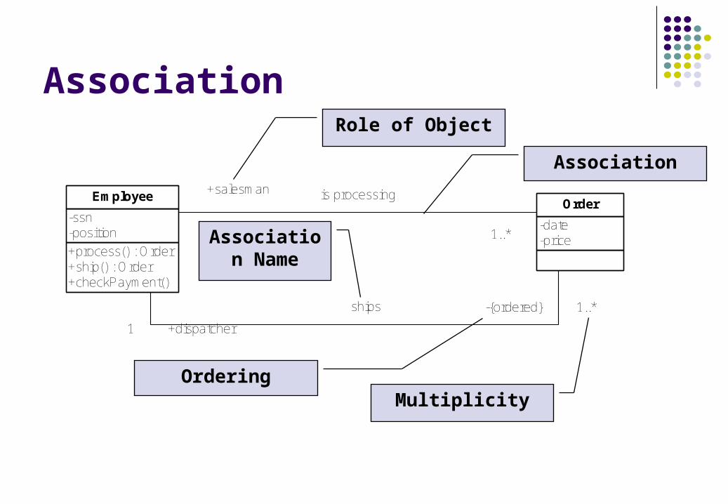
Association
+process() : Order+ship() : Order+checkPayment()
-ssn-position
Employee
-date-price
Order+salesman
1 1..*
is processing
+dispatcher1
-{ordered} 1..*ships
Role of Object
Association
MultiplicityOrdering
Association Name
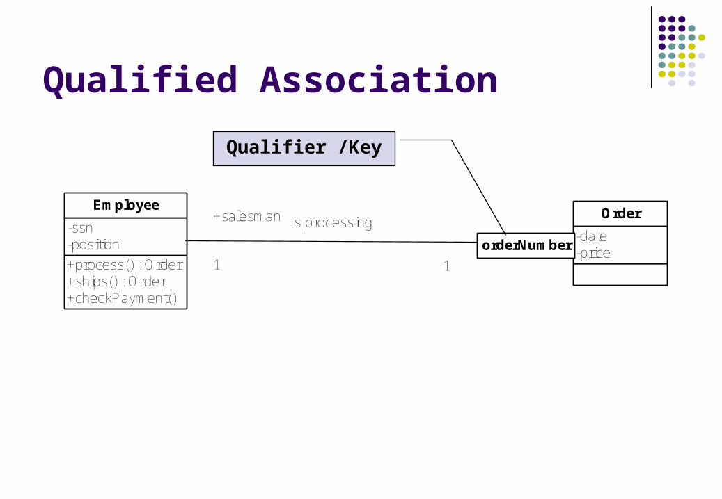
Qualified Association
+process() : Order+ships() : Order+checkPayment()
-ssn-position
Employee
-date-price
Order+salesman
1 1
is processing
orderNumber
Qualifier /Key
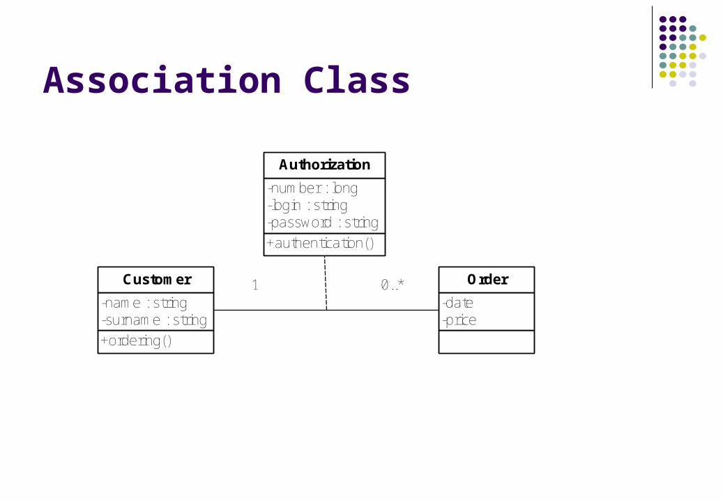
Association Class
+ordering()
-name : string-surname : string
Customer
-date-price
Order
+authentication()
-number : long-login : string-password : string
Authorization
1 0..*
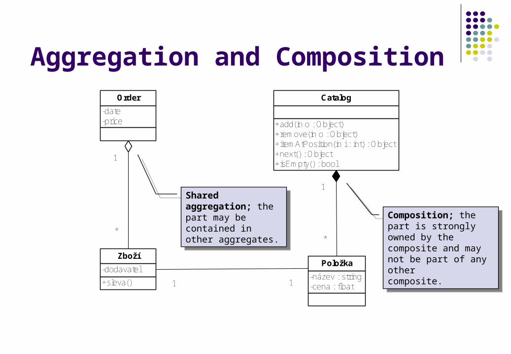
Aggregation and Composition
+add(in o : Object)+remove(in o : Object)+itemAtPosition(in i : int) : Object+next() : Object+isEmpty() : bool
Catalog
-název : string-cena : float
Položka
1
*
-date-price
Order
+sleva()
-dodavatel
Zboží
1
*
1 1
Shared aggregation; the part may be contained in other aggregates.
Shared aggregation; the part may be contained in other aggregates. Composition; the part is
strongly owned by the composite and may not be part of any othercomposite.
Composition; the part is strongly owned by the composite and may not be part of any othercomposite.
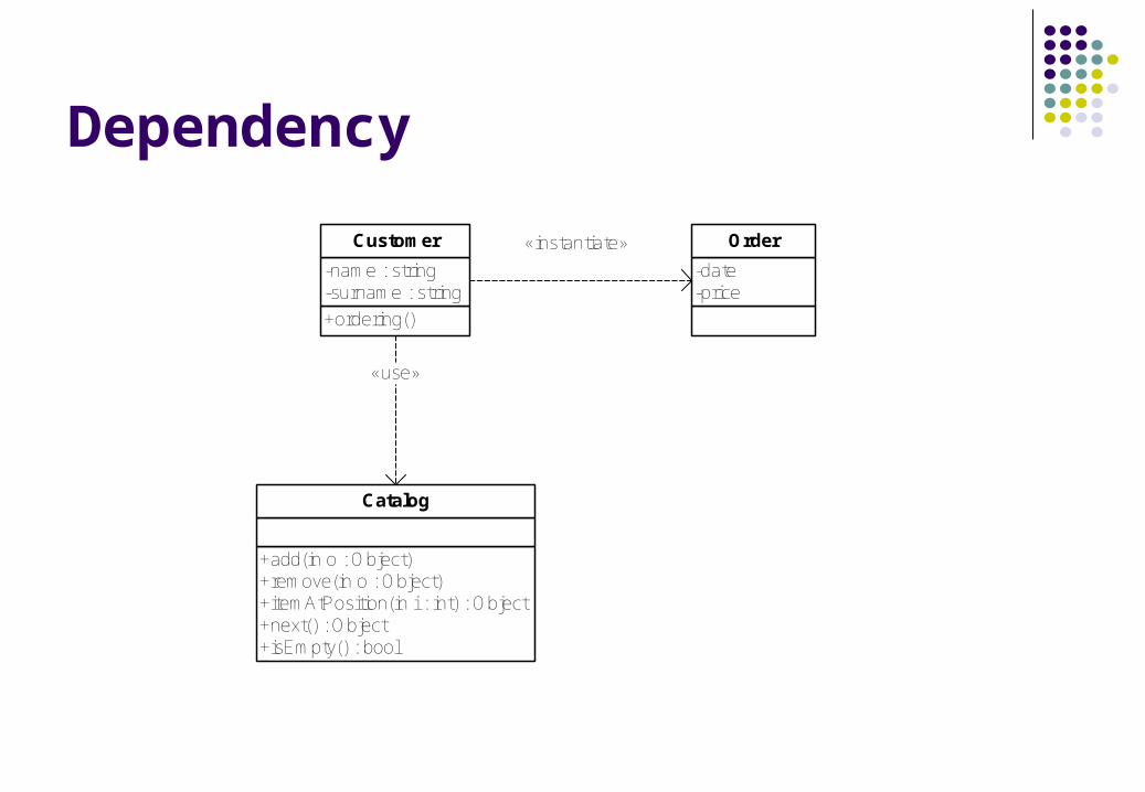
Dependency
+ordering()
-name : string-surname : string
Customer
-date-price
Order
+add(in o : Object)+remove(in o : Object)+itemAtPosition(in i : int) : Object+next() : Object+isEmpty() : bool
Catalog
«instantiate»
«use»
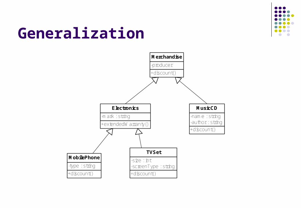
Generalization
+discount()
-producer
Merchandise
+extendedWarranty()
-mark : string
Electronics
+discount()
-name : string-author : string
MusicCD
+discount()
-type : string
MobilePhone
+discount()
-size : int-screenType : string
TVSet
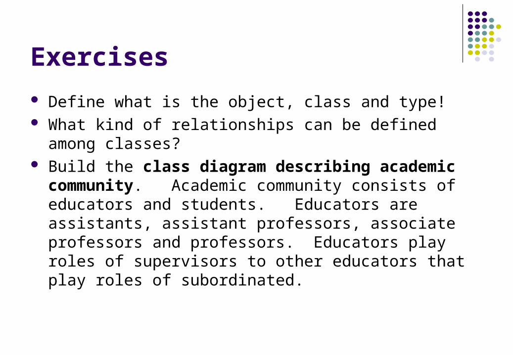
Exercises
Define what is the object, class and type! What kind of relationships can be defined among classes? Build the class diagram describing academic community.
Academic community consists of educators and students. Educators are assistants, assistant professors, associate professors and professors. Educators play roles of supervisors to other educators that play roles of subordinated.
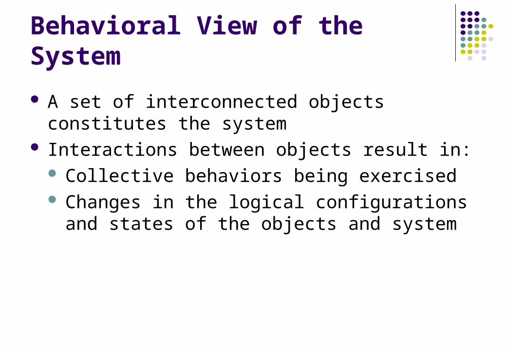
Behavioral View of the System
A set of interconnected objects constitutes the system
Interactions between objects result in: Collective behaviors being exercised Changes in the logical configurations and states of
the objects and system
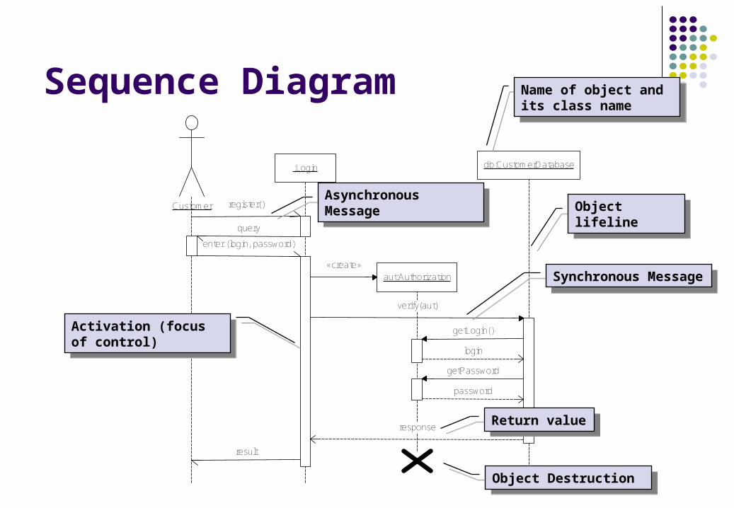
Sequence Diagram
Customer
:Login
aut:Authorization
db:CustomerDatabase
enter (login, password)
«create»
verify(aut)
register()
query
response
result
getLogin()
login
getPassword
password
Asynchronous MessageAsynchronous Message
Name of object and its class name
Name of object and its class name
Object lifelineObject lifeline
Object DestructionObject Destruction
Synchronous MessageSynchronous Message
Activation (focus of control)
Activation (focus of control)
Return valueReturn value
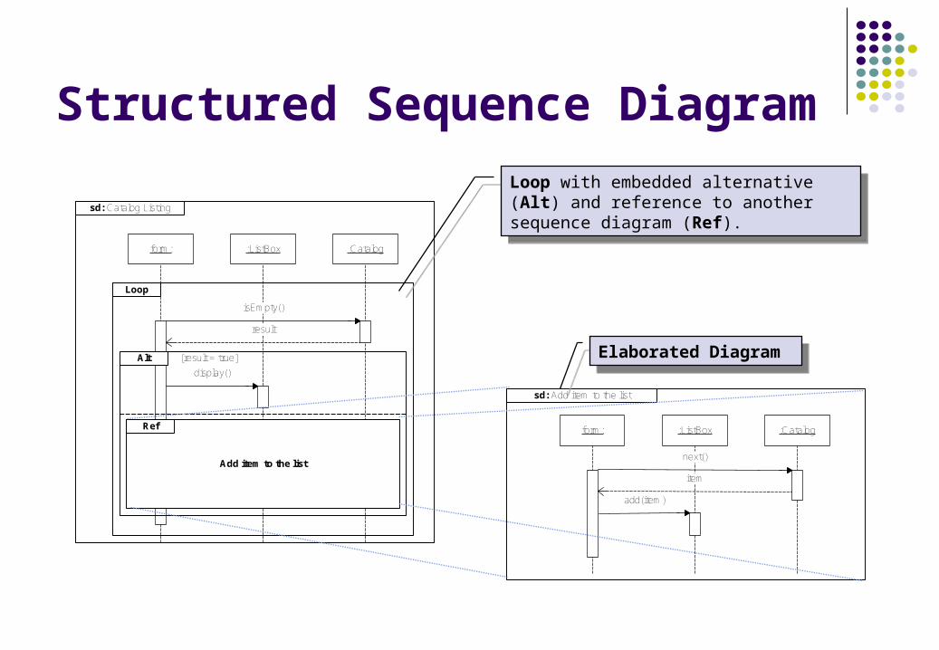
Structured Sequence Diagram
:Catalog:ListBoxform:
isEmpty()
result
další()
položka
display()
add(položka)
Loop
Alt [result = true]
Add item to the list
Ref
sd: Catalog Listing
:Catalog:ListBoxform:
next()
item
add(item)
sd: Add item to the list
Loop with embedded alternative (Alt) and reference to another sequence diagram (Ref).
Loop with embedded alternative (Alt) and reference to another sequence diagram (Ref).
Elaborated DiagramElaborated Diagram
The Dynamic Behavior of an Object
A state transition (statechart) diagram shows The life cycle of a given object The events causing a transition from one state to another The actions that result from a state change
State transition diagrams are created for objects with significant dynamic behavior
Sequence diagrams are examined to define statechart diagram of a class
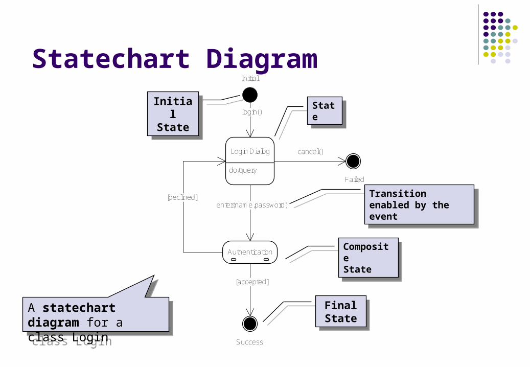
Statechart Diagram
do/query
Login Dialog
login()
Authentication
enter(name,password)
[accepted]
[declined]
cancel()
Initial
Success
Failed
InitialState
InitialState
FinalState
FinalState
A statechart diagram for a class Login
A statechart diagram for a class Login
StateState
CompositeState
CompositeState
Transition enabled by the event
Transition enabled by the event
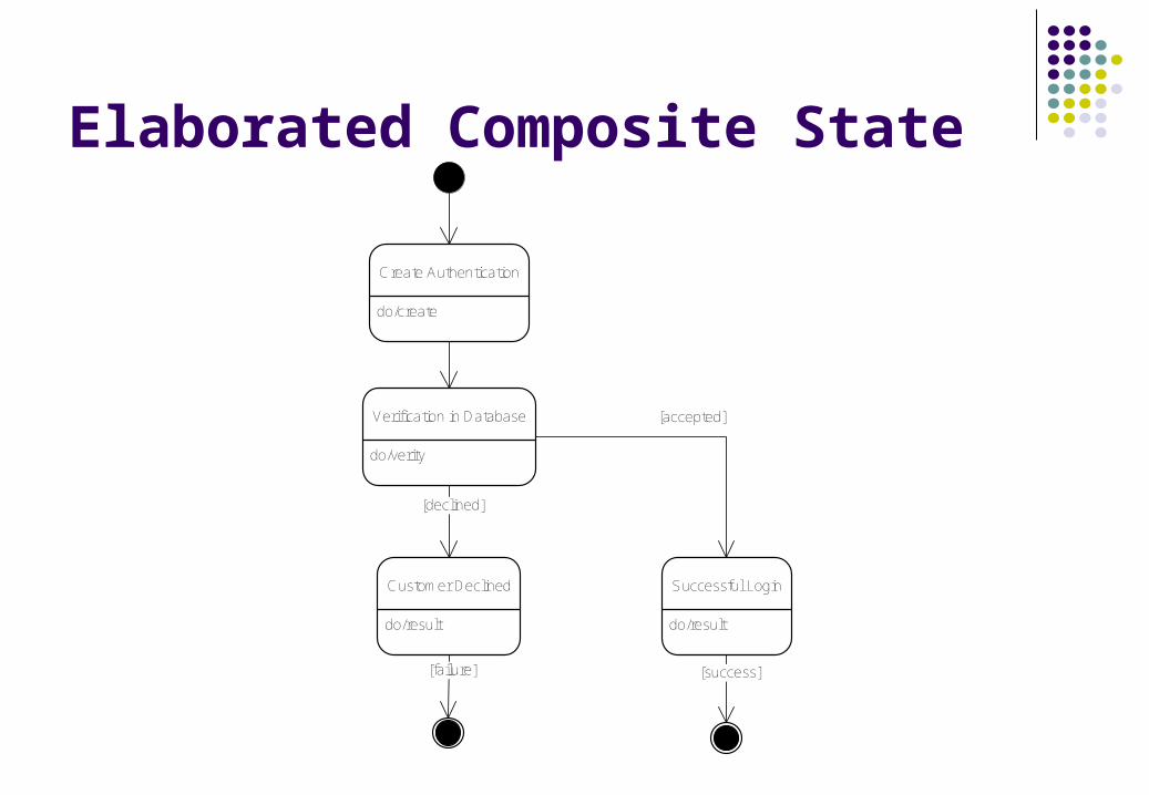
Elaborated Composite State
do/create
Create Authentication
do/verity
Verification in Database
do/result
Successful Login
do/result
Customer Declined
[accepted]
[success]
[declined]
[failure]
Workflow Modeling
Activity Diagram is a variation of a state machine in which the states represent the performance of activities and the transitions are triggered by their completion. The purpose of this diagram is to focus on flows
driven by internal processing.
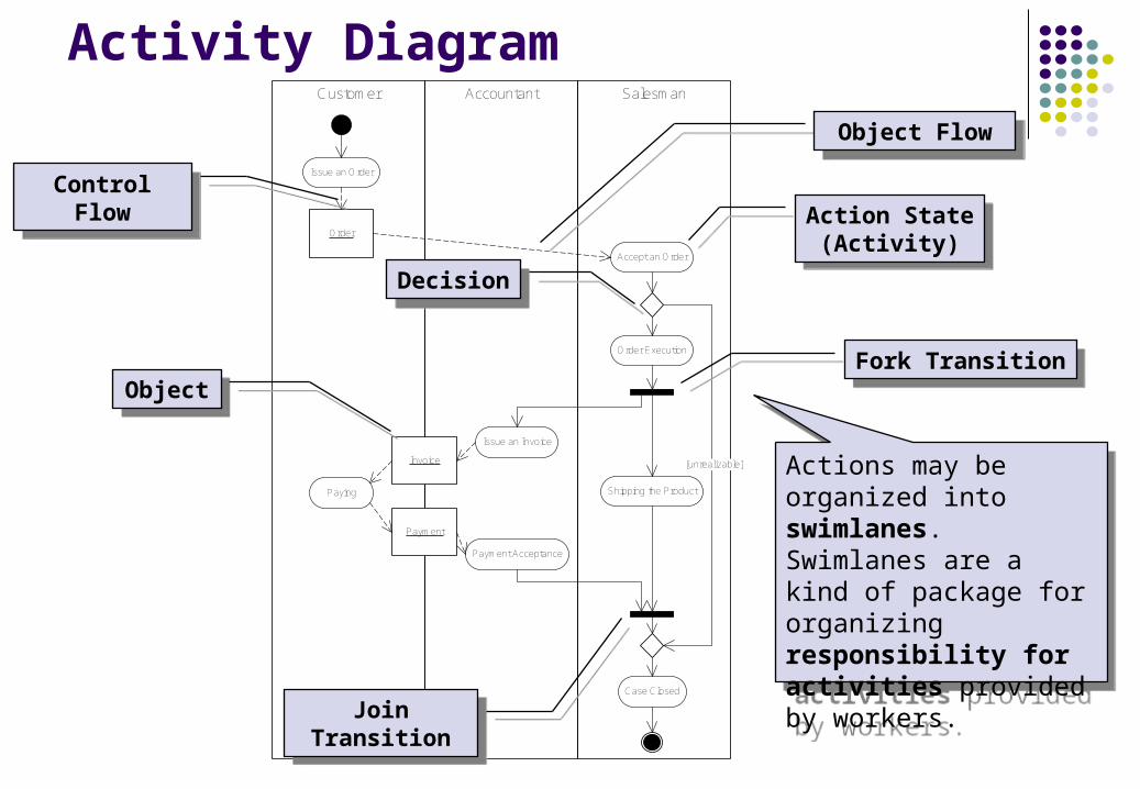
Activity DiagramSalesmanAccountantCustomer
Order
Accept an Order
Order Execution
Issue an Invoice
Invoice
Shipping the ProductPaying
Payment Acceptance
Payment
[unrealizable]
Case Closed
Issue an Order
Action State(Activity)
Action State(Activity)
DecisionDecision
ControlFlow
ControlFlow
Join TransitionJoin Transition
Fork TransitionFork Transition
Object FlowObject Flow
ObjectObject
Actions may be organized into swimlanes. Swimlanes are a kind of package for organizing responsibility for activities provided by workers.
Actions may be organized into swimlanes. Swimlanes are a kind of package for organizing responsibility for activities provided by workers.
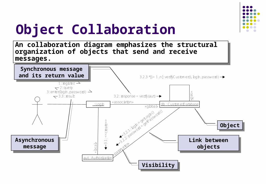
Object CollaborationAn collaboration diagram emphasizes the structural organization of objects that send and receive messages.
An collaboration diagram emphasizes the structural organization of objects that send and receive messages.
: Login
aut : Authorization
db : CustomerDatabase
1: register2: query
3: enter(login, password)3.3: result
3.1
: <<
crea
te>
>
«lo
cal»
3.2: response = verify(aut)
«association»«global»
3.2.1: login = getLogin()
3.2.2: pass
word = getPass
word()
«parameter»
3.2.3 *[i = 1..n]: verifyCustomer(i, login, password)«
self»
ObjectObject
Synchronous message and its return value
Synchronous message and its return value
Asynchronous message
Asynchronous message
VisibilityVisibility
Link between objectsLink between objects
Exercises
What is the difference between sequence and collaboration diagram?
What is the purpose of state chart diagram? Build a sequence diagram for the task of money withdrawal
from ATM. Consider interaction between Client, ATM and Credit Card.
Implementation View of the System
Implementation Model describes how elements in the design model, such as design classes, are implemented in terms of components such as a source code files, executables, and so on. The implementation model also describes how the components are organized according to the structuring and modularization mechanism available in the implementation environment and the programming language (e.g. package in Java).
The goal of the implementation workflow is to flesh out the designed architecture and the system as a whole.The goal of the implementation workflow is to flesh out the designed architecture and the system as a whole.
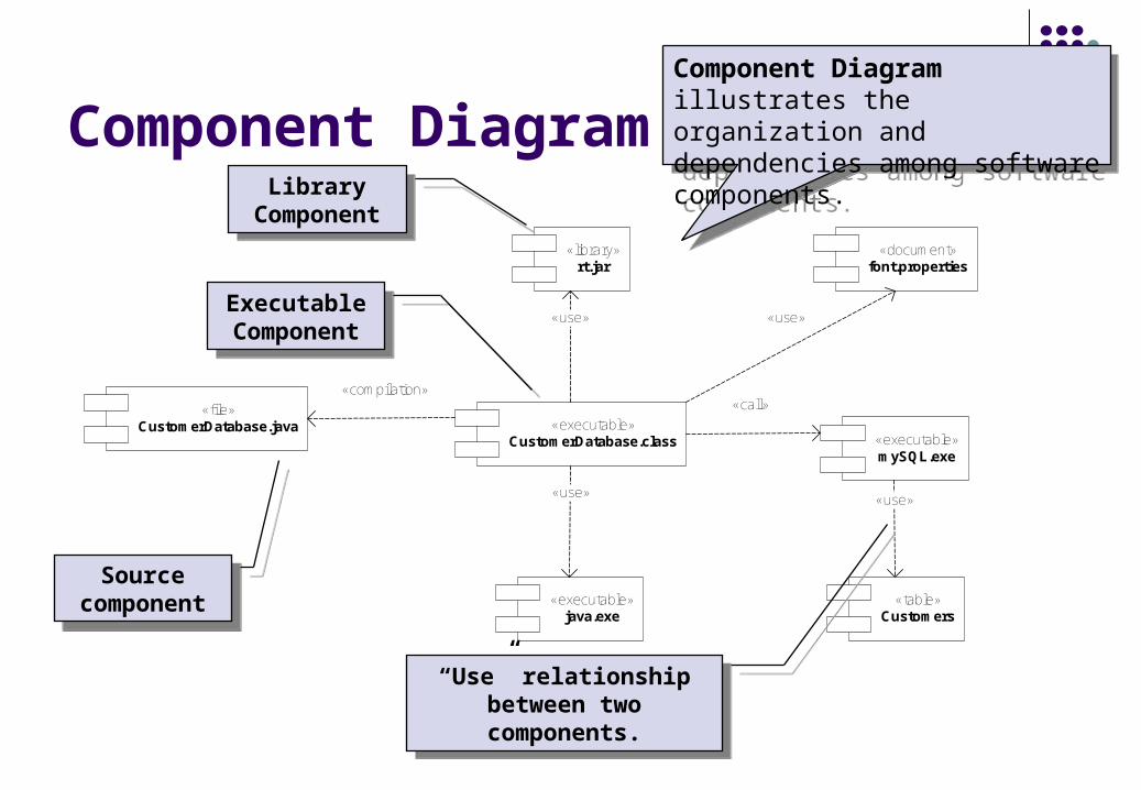
Component Diagram
«library»rt.jar
«document»font.properties
«executable»CustomerDatabase.class
«table»Customers
«executable»java.exe
«file»CustomerDatabase.java
«executable»mySQL.exe
«use» «use»
«call»
«use»«use»
«compilation»
Library Component
Library Component
Source component
Source component
Executable Component
Executable Component
“Use” relationship between two components.
“Use” relationship between two components.
Component Diagram illustrates the organization and dependencies among software components.
Component Diagram illustrates the organization and dependencies among software components.
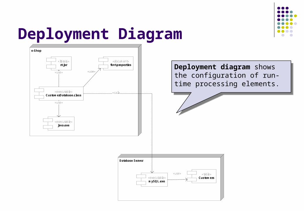
Deployment Diagrame-Shop
Database Server
«executable»CustomerDatabase.class
«executable»java.exe
«use»
«document»font.properties
«use»
«library»rt.jar
«use»
«executable»mySQL.exe
«call»
«table»Customers
«use»
Deployment diagram shows the configuration of run-time processing elements.
Deployment diagram shows the configuration of run-time processing elements.
Exercises
Define deployment diagram for e-Shop based on .Net technology.
Formal Methods
Formal methods include Formal specification Specification analysis and proof Transformational development Program verification
Language for formal specification has to have precise and unambiguous syntax and semantics.
Techniques for the precise and unambiguous specification of softwareTechniques for the precise and unambiguous specification of software
Mathematical Representation of Software
Formal specifications are expressed in a mathematical notation with precisely defined vocabulary, syntax and semantics.
Algebraic approach The system is specified in terms of its operations and their
relationships. Model-based approach
The system is specified in terms of a state model that is constructed using mathematical constructs such as sets and sequences.
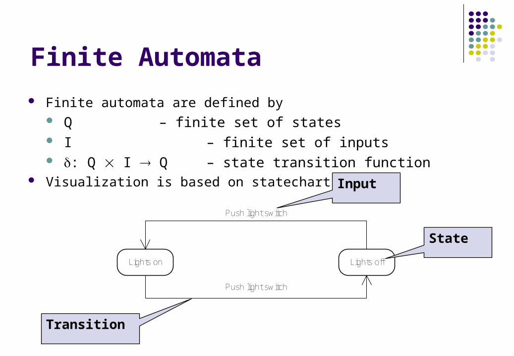
Finite Automata
Finite automata are defined by Q – finite set of states I – finite set of inputs : Q I Q – state transition function
Visualization is based on statechart diagrams
Lights on Lights off
Push light switch
Push light switch
Input
State
Transition
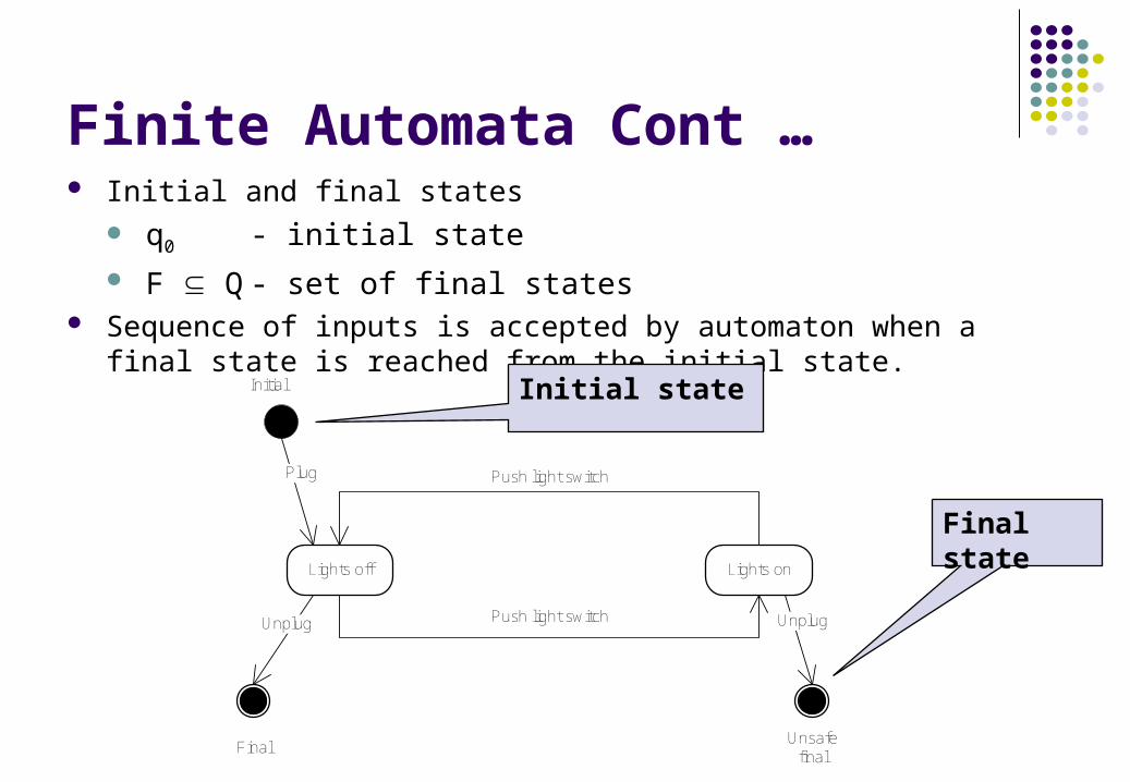
Finite Automata Cont … Initial and final states
q0 - initial state F Q - set of final states
Sequence of inputs is accepted by automaton when a final state is reached from the initial state.
Lights off Lights on
Push light switch
Push light switch Plug
Initial
Unplug Unplug
FinalUnsafe
final
Initial state
Final state
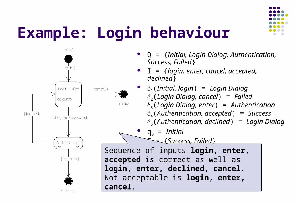
Example: Login behaviour Q = {Initial, Login Dialog, Authentication,
Success, Failed} I = {login, enter, cancel, accepted, declined} 1(Initial, login) = Login Dialog
2(Login Dialog, cancel) = Failed3(Login Dialog, enter) = Authentication4(Authentication, accepted) = Success5(Authentication, declined) = Login Dialog
q0 = Initial F = {Success, Failed}
do/query
Login Dialog
login()
Authentication
enter(name,password)
[accepted]
[declined]
cancel()
Initial
Success
Failed
Sequence of inputs login, enter, accepted is correct as well as login, enter, declined, cancel. Not acceptable is login, enter, cancel.
Key Issues
Formal methods reduce number of errors in software but the mathematical representation requires more time to market software product.
Formal methods are hard to scale up to large systems. The main area of their applicability is critical systems. In this
area the use of formal methods seems to be cost-effective. The idea is to combine formal methods with diagrammatic
languages like UML. The formal methods specify what cannot be captured by diagrams.
MDA – Model Driven Architecture
The software development process is driven by the activity of modeling of software system.
The MDA process is divided into three steps: Build a model with high level of abstraction that is independent of
any implementation technology (Platform Independent Model – PIM) Transform the PIM into one or more model tailored for
implementation constructs specific to actual implemenation technology (Platform Specific Model – PSM)
Transform the PSMs to code. Key requirement: automation of transformations. Models have to be
precise and unambiguous.
MDA is a framework that defines how models defined in one language can be transformed into models in other languages.
MDA is a framework that defines how models defined in one language can be transformed into models in other languages.
UML Limitations
UML modeling is based on producing diagrams. The information conveyed by such a model has a tendency to be incomplete, imprecise and even inconsistent.
Diagrams cannot express the statements that should be part of a specification.
Interpretation of model can be unambiguous.
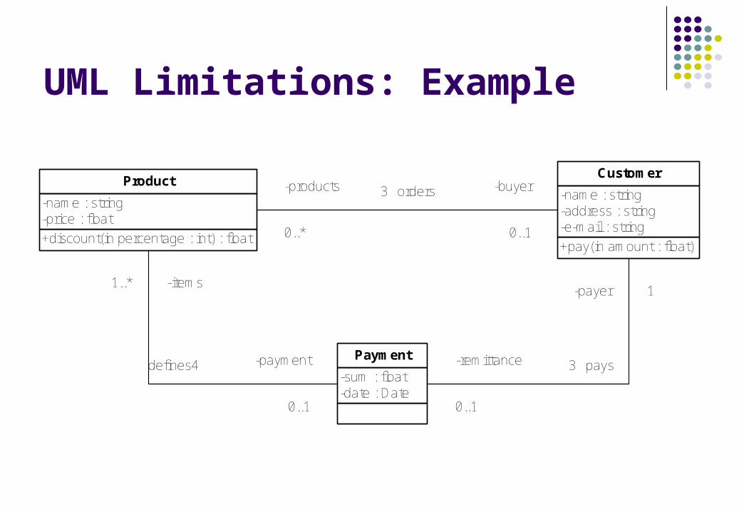
UML Limitations: Example
+discount(in percentage : int) : float
-name : string-price : float
Product
+pay(in amount : float)
-name : string-address : string-e-mail : string
Customer
-sum : float-date : Date
Payment
-products
0..*
-buyer
0..1
3 orders
-items1..*
-payment
0..1
defines4 -remittance
0..1
-payer 1
3 pays
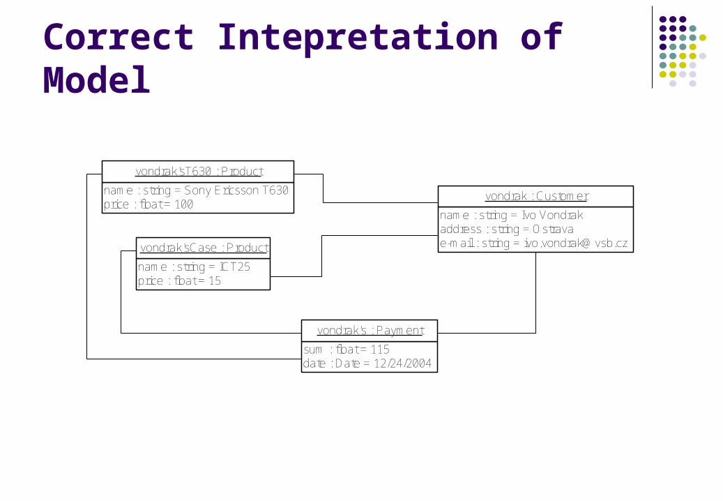
Correct Intepretation of Model
name : string = Ivo Vondrakaddress : string = Ostravae-mail : string = [email protected]
vondrak : Customername : string = Sony Ericsson T630price : float = 100
vondrak'sT630 : Product
name : string = ICT25price : float = 15
vondrak'sCase : Product
sum : float = 115date : Date = 12/24/2004
vondrak's : Payment
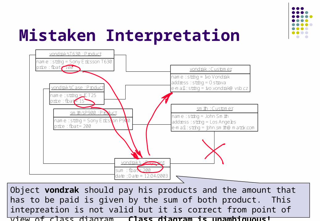
Mistaken Interpretation
name : string = John Smithaddress : string = Los Angelese-mail : string = [email protected]
smith : Customer
name : string = Sony Ericsson T630price : float = 100
vondrak'sT630 : Product
name : string = ICT25price : float = 15
vondrak'sCase : Product
sum : float = 200date : Date = 12/24/2003
vondrak's : Payment
name : string = Ivo Vondrakaddress : string = Ostravae-mail : string = [email protected]
vondrak : Customer
name : string = Sony Ericsson P900price : float = 200
smith'sP900 : Product
Object vondrak should pay his products and the amount that has to be paid is given by the sum of both product. This intepreation is not valid but it is correct from point of view of class diagram. Class diagram is unambiguous!
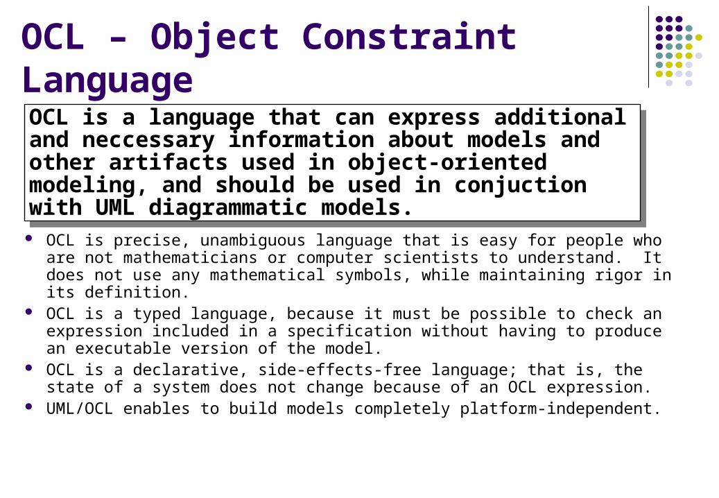
OCL – Object Constraint Language
OCL is precise, unambiguous language that is easy for people who are not mathematicians or computer scientists to understand. It does not use any mathematical symbols, while maintaining rigor in its definition.
OCL is a typed language, because it must be possible to check an expression included in a specification without having to produce an executable version of the model.
OCL is a declarative, side-effects-free language; that is, the state of a system does not change because of an OCL expression.
UML/OCL enables to build models completely platform-independent.
OCL is a language that can express additional and neccessary information about models and other artifacts used in object-oriented modeling, and should be used in conjuction with UML diagrammatic models.
OCL is a language that can express additional and neccessary information about models and other artifacts used in object-oriented modeling, and should be used in conjuction with UML diagrammatic models.
How to Combine UML and OCL
Rules related to the class diagram of e-shop: A payment is valid only when the products ordered by a
customer are paid by the same customer. The e-mail address has to be unique. The payment sum is given by the sum of all ordered products’
prices. Customer has to pay amount of money equal to the payment
sum.
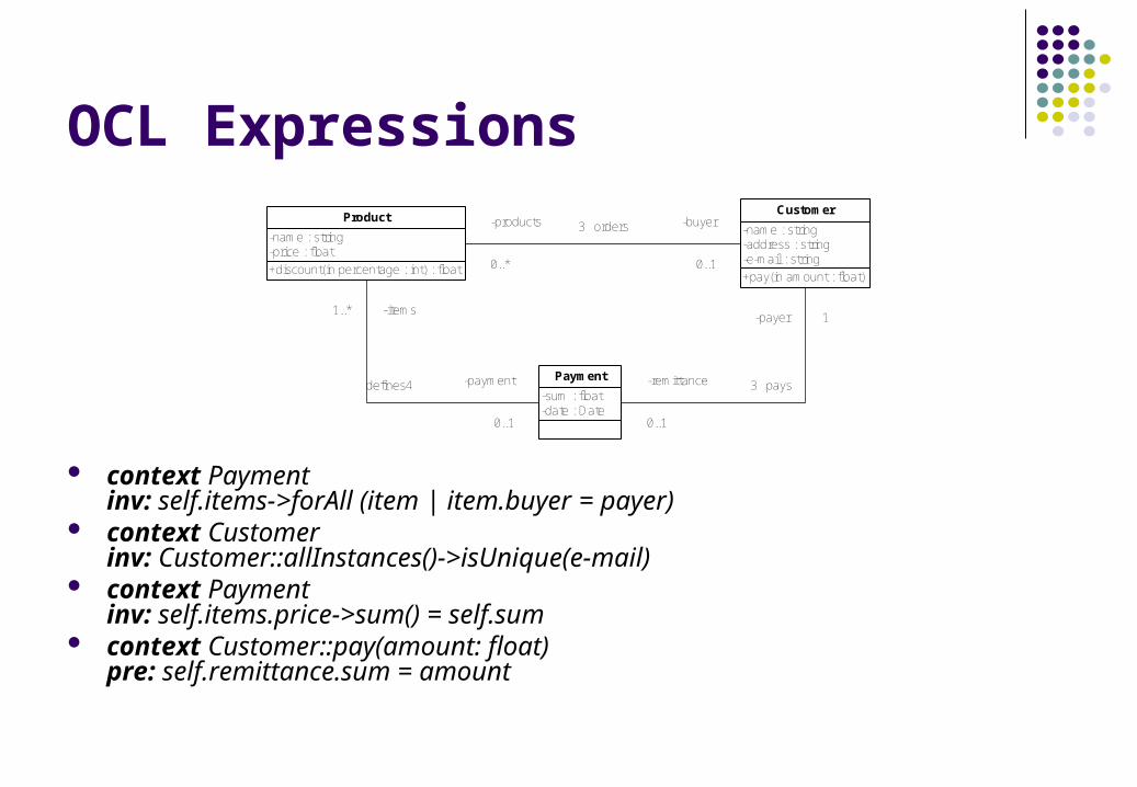
OCL Expressions
context Paymentinv: self.items->forAll (item | item.buyer = payer)
context Customerinv: Customer::allInstances()->isUnique(e-mail)
context Paymentinv: self.items.price->sum() = self.sum
context Customer::pay(amount: float)pre: self.remittance.sum = amount
+discount(in percentage : int) : float
-name : string-price : float
Product
+pay(in amount : float)
-name : string-address : string-e-mail : string
Customer
-sum : float-date : Date
Payment
-products
0..*
-buyer
0..1
3 orders
-items1..*
-payment
0..1
defines4 -remittance
0..1
-payer 1
3 pays
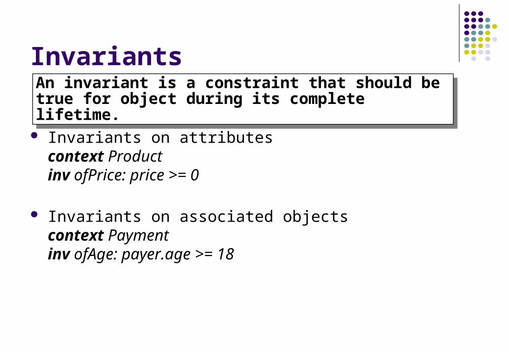
Invariants
Invariants on attributescontext Productinv ofPrice: price >= 0
Invariants on associated objectscontext Paymentinv ofAge: payer.age >= 18
An invariant is a constraint that should be true for object during its complete lifetime.An invariant is a constraint that should be true for object during its complete lifetime.
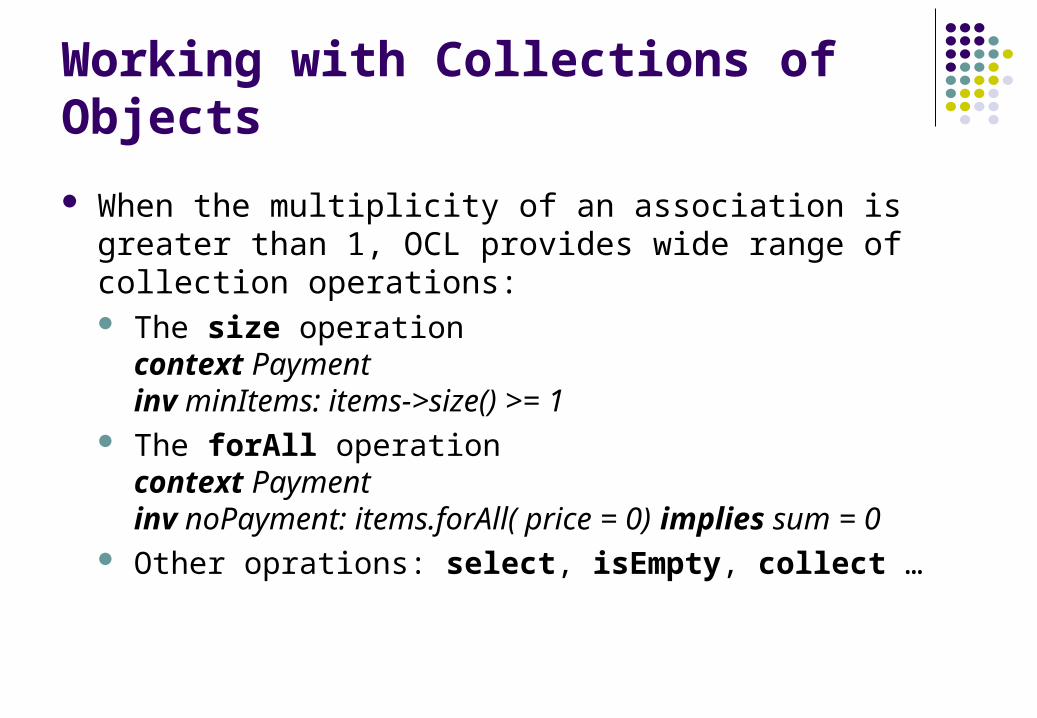
Working with Collections of Objects
When the multiplicity of an association is greater than 1, OCL provides wide range of collection operations: The size operationcontext Paymentinv minItems: items->size() >= 1
The forAll operationcontext Paymentinv noPayment: items.forAll( price = 0) implies sum = 0
Other oprations: select, isEmpty, collect …
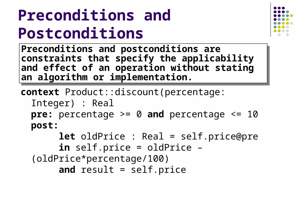
Preconditions and Postconditions
context Product::discount(percentage: Integer) : Realpre: percentage >= 0 and percentage <= 10 post:
let oldPrice : Real = self.price@prein self.price = oldPrice – (oldPrice*percentage/100)and result = self.price
Preconditions and postconditions are constraints that specify the applicability and effect of an operation without stating an algorithm or implementation.
Preconditions and postconditions are constraints that specify the applicability and effect of an operation without stating an algorithm or implementation.
Exerices
What is definition of Invariant? Specify the invariant for class Customer that reflects
following constraint: Customer’s payment contains all products that were ordered by the customer.
Design Patterns
The design pattern concept can be viewed as an abstraction of imitating useful parts of other software products.
The design pattern is description of communicating objects and classes that are customized to solve a general design problem in a particular context.
Classification of Design Patterns
Creational patterns defer some part of object creation to a subclass or another object.
Structural patterns composes classes or objects. Behavioral patterns describe algorithms or cooperation of
objects.
Creational Design Patterns
Factory Method define an interface for creating an object, but let subclasses decide which class to instantiate.
Factory provides an interface for creating families of related objects without specifying their concrete classes.
Prototype specifies the kinds of objects to create using a prototypical instance, and create new objects by copying this prototype.
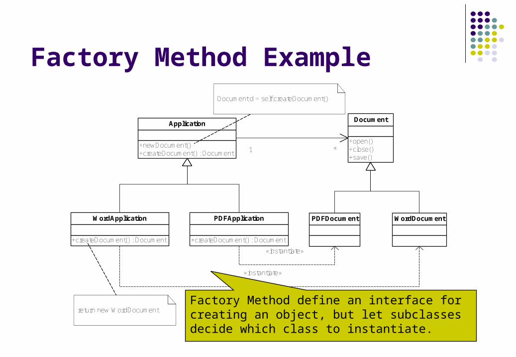
Factory Method Example
+newDocument()+createDocument() : Document
Application
1 *+open()+close()+save()
Document
PDFDocument WordDocument
+createDocument() : Document
WordApplication
+createDocument() : Document
PDFApplication
«instantiate»
«instantiate»
return new WordDocument
Document d = self.createDocument()
Factory Method define an interface for creating an object, but let subclasses decide which class to instantiate.
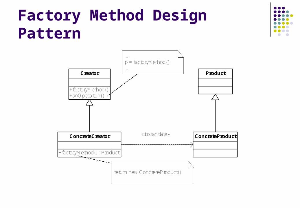
Factory Method Design Pattern
+factoryMethod()+anOperation()
Creator Product
ConcreteProduct
+factoryMethod() : Product
ConcreteCreator «instantiate»
...p = factoryMethod()...
return new ConcreteProduct()
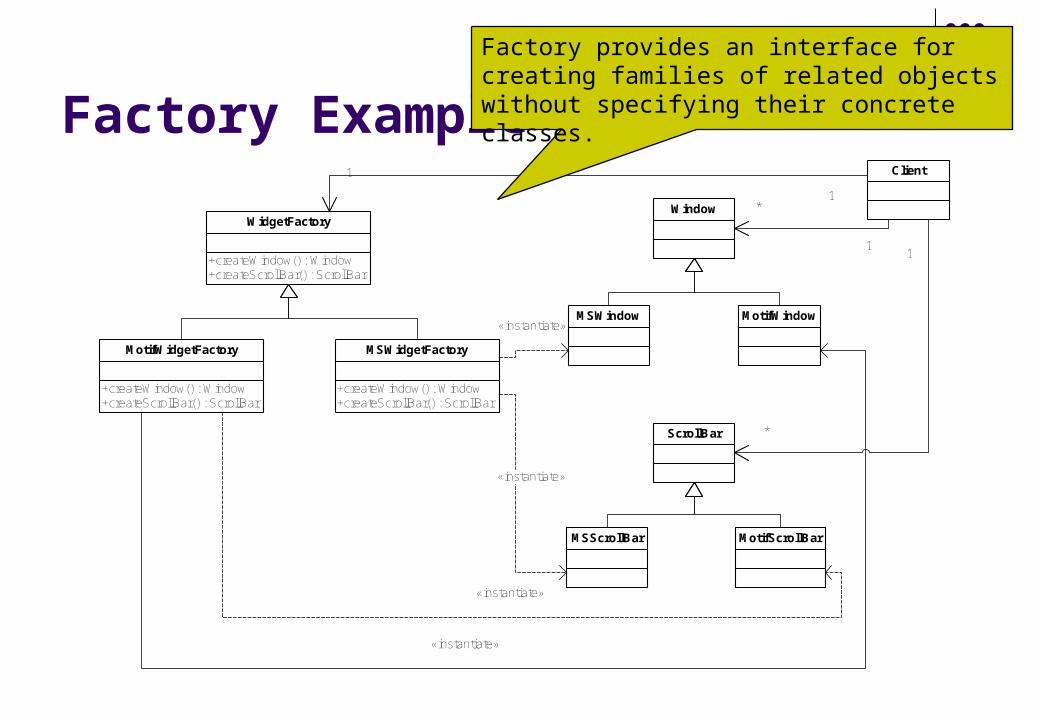
Factory Example
+createWindow() : Window+createScrollBar() : ScrollBar
WidgetFactoryWindow
MSWindow MotifWindow
ScrollBar
MSScrollBar MotifScrollBar
+createWindow() : Window+createScrollBar() : ScrollBar
MotifWidgetFactory
+createWindow() : Window+createScrollBar() : ScrollBar
MSWidgetFactory
«instantiate»
«instantiate»
«instantiate»
«instantiate»
Client1
1
1
*
1
*
Factory provides an interface for creating families of related objects without specifying their concrete classes.
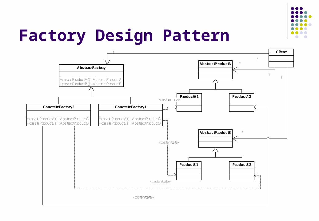
Factory Design Pattern
+createProductA() : AbstractProductA+createProductB() : AbstractProductB
AbstractFactoryAbstractProductA
ProductA1 ProductA2
AbstractProductB
ProductB1 ProductB2
+createProductA() : AbstractProductA+createProductB() : AbstractProductB
ConcreteFactory2
+createProductA() : AbstractProductA+createProductB() : AbstractProductB
ConcreteFactory1
«instantiate»
«instantiate»
«instantiate»
«instantiate»
Client1
1
1
*
1
*
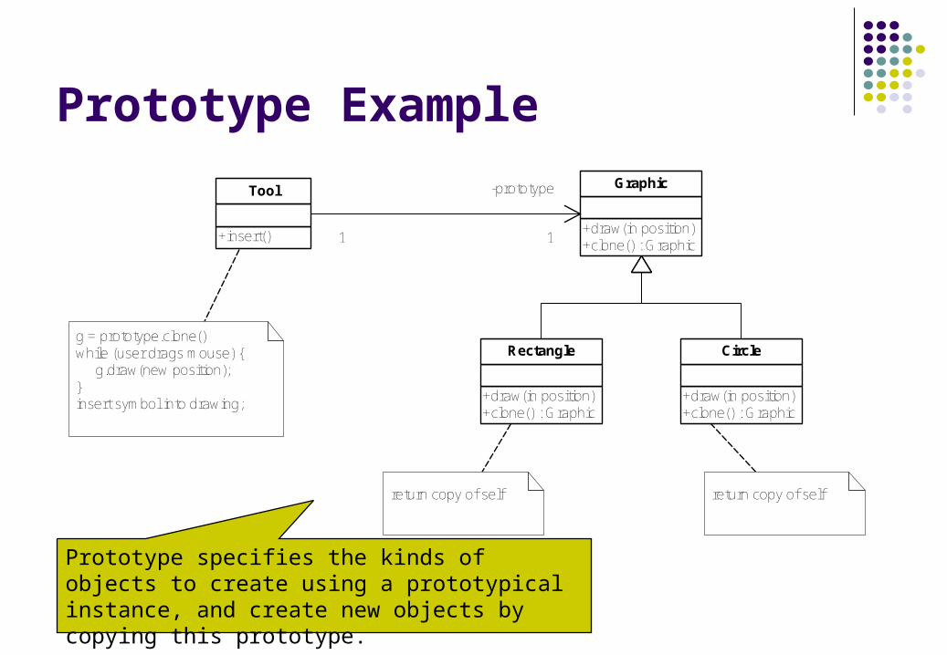
Prototype Example
+insert()
Tool
+draw(in position)+clone() : Graphic
Graphic
+draw(in position)+clone() : Graphic
Rectangle
+draw(in position)+clone() : Graphic
Circle
1
-prototype
1
g = prototype.clone()while (user drags mouse) { g.draw(new position);}insert symbol into drawing;
return copy of self return copy of self
Prototype specifies the kinds of objects to create using a prototypical instance, and create new objects by copying this prototype.
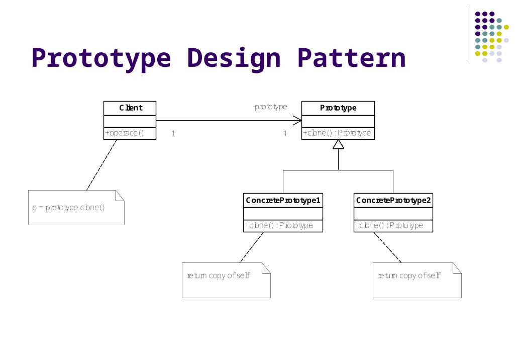
Prototype Design Pattern
+operace()
Client
+clone() : Prototype
Prototype
+clone() : Prototype
ConcretePrototype1
+clone() : Prototype
ConcretePrototype2
1
-prototype
1
p = prototype.clone()
return copy of self return copy of self
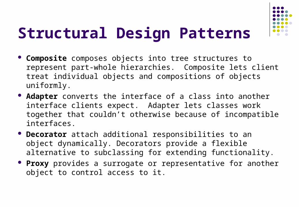
Structural Design Patterns
Composite composes objects into tree structures to represent part-whole hierarchies. Composite lets client treat individual objects and compositions of objects uniformly.
Adapter converts the interface of a class into another interface clients expect. Adapter lets classes work together that couldn’t otherwise because of incompatible interfaces.
Decorator attach additional responsibilities to an object dynamically. Decorators provide a flexible alternative to subclassing for extending functionality.
Proxy provides a surrogate or representative for another object to control access to it.
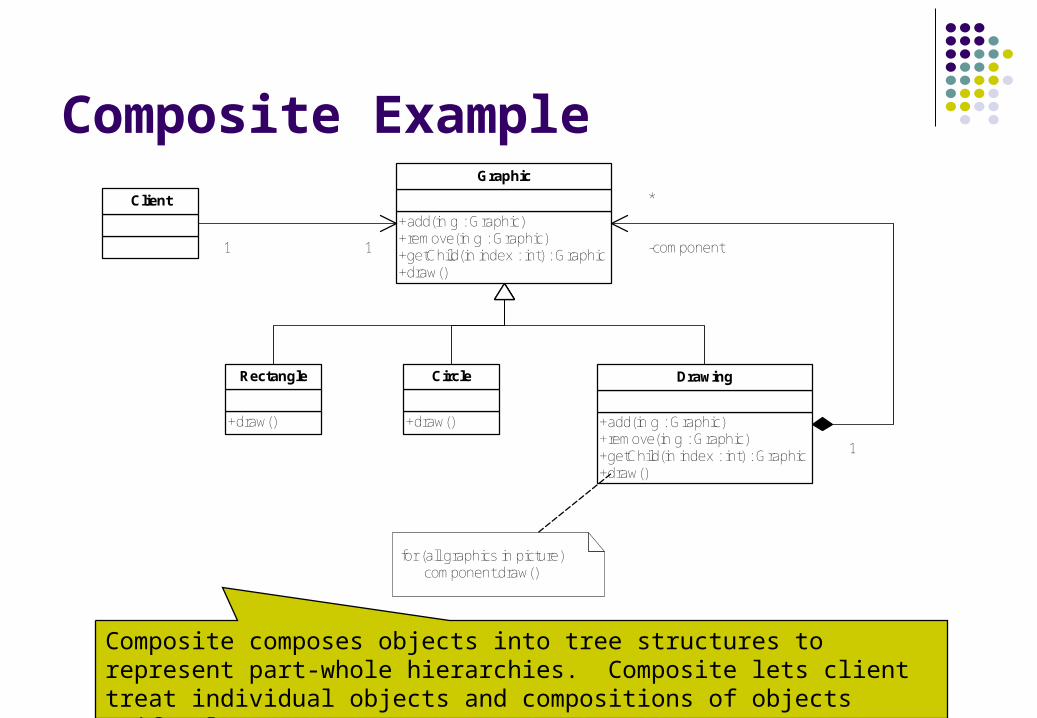
Composite Example
Client
+add(in g : Graphic)+remove(in g : Graphic)+getChild(in index : int) : Graphic+draw()
Graphic
+draw()
Rectangle
+draw()
Circle
+add(in g : Graphic)+remove(in g : Graphic)+getChild(in index : int) : Graphic+draw()
Drawing
1
-component
*
1 1
for (all graphics in picture) component.draw()
Composite composes objects into tree structures to represent part-whole hierarchies. Composite lets client treat individual objects and compositions of objects uniformly.
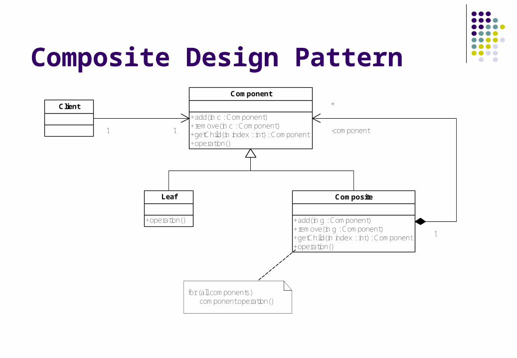
Composite Design Pattern
Client
+add(in c : Component)+remove(in c : Component)+getChild(in index : int) : Component+operation()
Component
+operation()
Leaf
+add(in g : Component)+remove(in g : Component)+getChild(in index : int) : Component+operation()
Composite
1
-component
*
1 1
for (all components) component.operation()
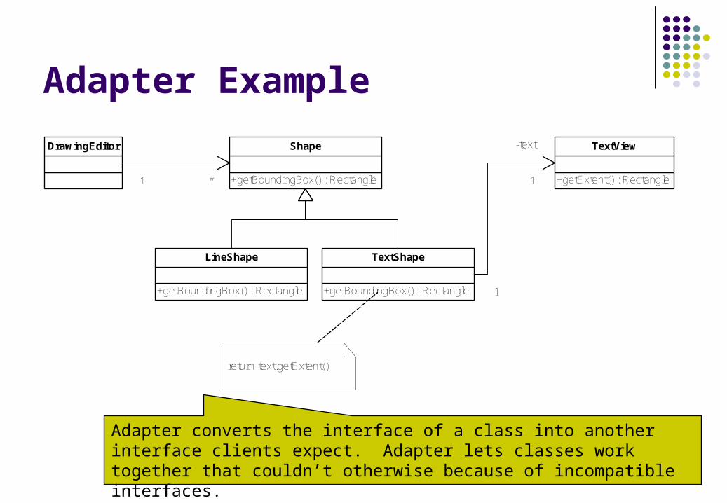
Adapter Example
DrawingEditor
+getBoundingBox() : Rectangle
Shape
+getBoundingBox() : Rectangle
LineShape
+getBoundingBox() : Rectangle
TextShape
+getExtent() : Rectangle
TextView
1 *
1
-text
1
return text.getExtent()
Adapter converts the interface of a class into another interface clients expect. Adapter lets classes work together that couldn’t otherwise because of incompatible interfaces.
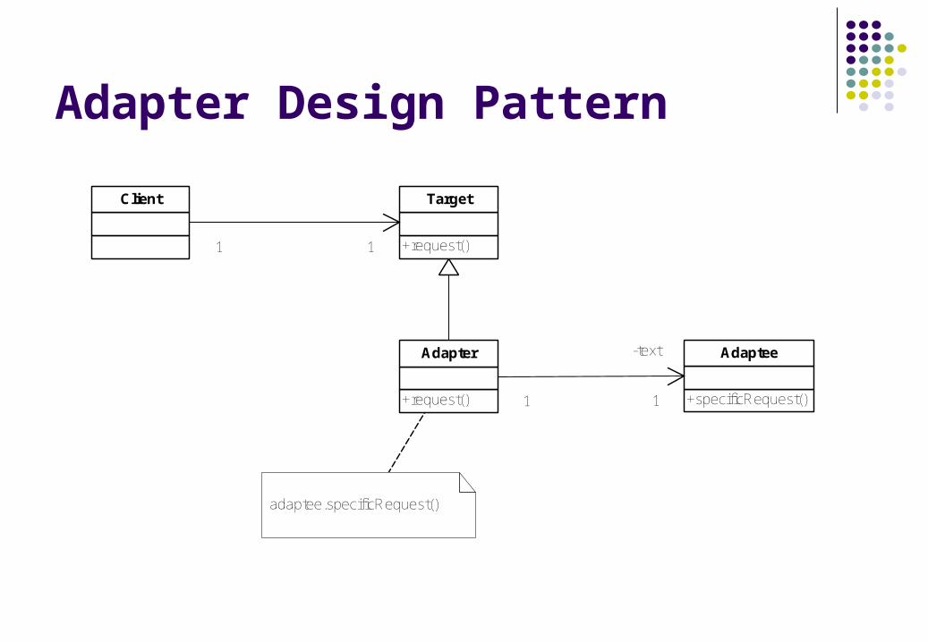
Adapter Design Pattern
Client
+request()
Target
+request()
Adapter
+specificRequest()
Adaptee
1 1
1
-text
1
adaptee.specificRequest()
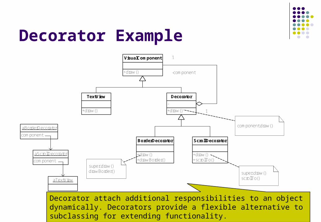
Decorator Example
+draw()
VisualComponent
+draw()
TextView
+draw()
-
Decorator
+draw()+drawBorder()
BorderDecorator
+draw()+scrollTo()
ScrollDecorator
1
-component
1
component.draw()
super.draw()scrollTo()
super.draw()drawBorder()
component
aBorderDecorator
component
aScrollDecorator
aTextView
Decorator attach additional responsibilities to an object dynamically. Decorators provide a flexible alternative to subclassing for extending functionality.
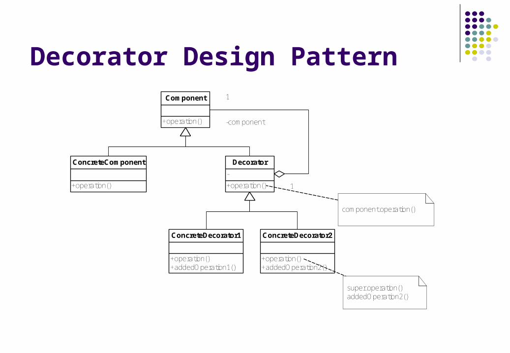
Decorator Design Pattern
+operation()
Component
+operation()
ConcreteComponent
+operation()
-
Decorator
+operation()+addedOperation1()
ConcreteDecorator1
+operation()+addedOperation2()
ConcreteDecorator2
1
-component
1
component.operation()
super.operation()addedOperation2()
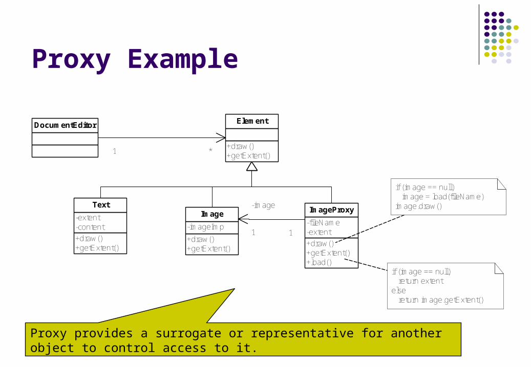
Proxy Example
DocumentEditor
+draw()+getExtent()
Element
+draw()+getExtent()
-extent-content
Text
+draw()+getExtent()
-imageImp
Image
+draw()+getExtent()+load()
-fileName-extent
ImageProxy
1 *
-image
1 1
if (image == null) image = load(fileName)image.draw()
if (image == null) return extentelse return image.getExtent()
Proxy provides a surrogate or representative for another object to control access to it.
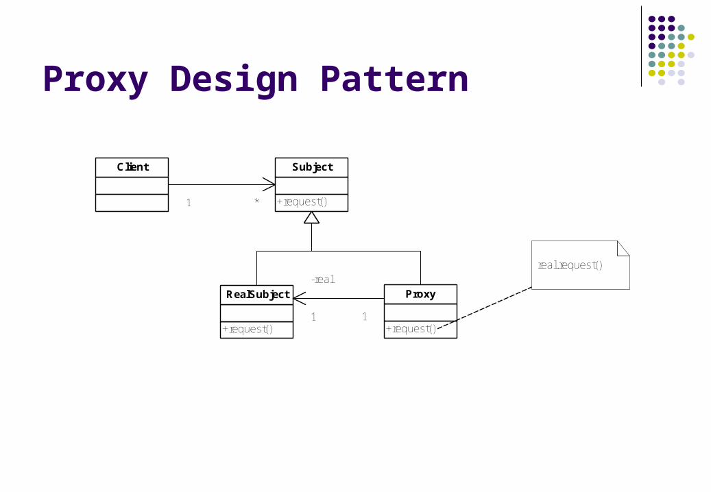
Proxy Design Pattern
Client
+request()
Subject
+request()
RealSubject
+request()
Proxy
1 *
-real
1 1
real.request()
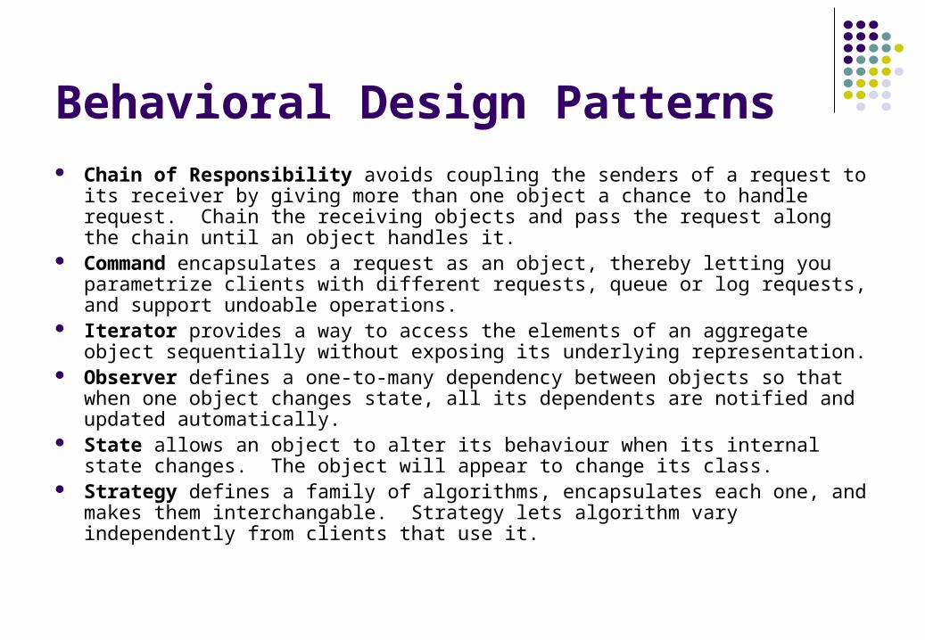
Behavioral Design Patterns Chain of Responsibility avoids coupling the senders of a request to its receiver
by giving more than one object a chance to handle request. Chain the receiving objects and pass the request along the chain until an object handles it.
Command encapsulates a request as an object, thereby letting you parametrize clients with different requests, queue or log requests, and support undoable operations.
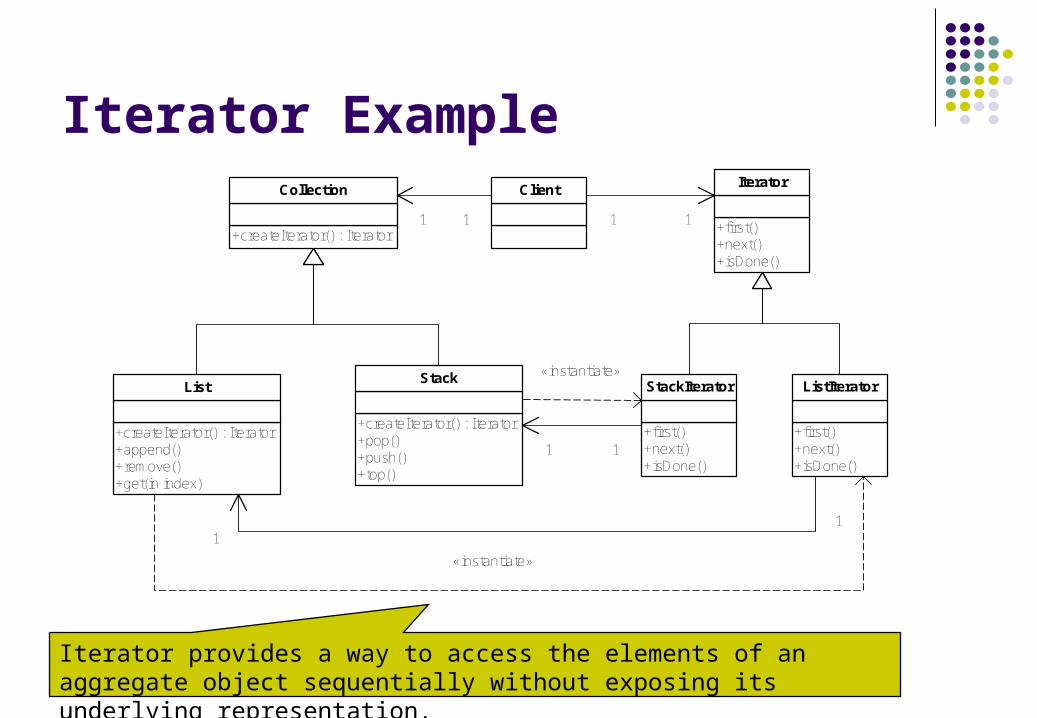
Iterator provides a way to access the elements of an aggregate object sequentially without exposing its underlying representation.
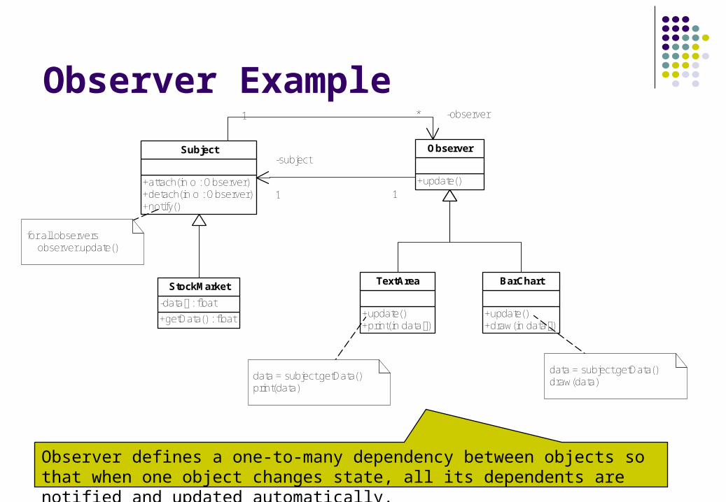
Observer defines a one-to-many dependency between objects so that when one object changes state, all its dependents are notified and updated automatically.
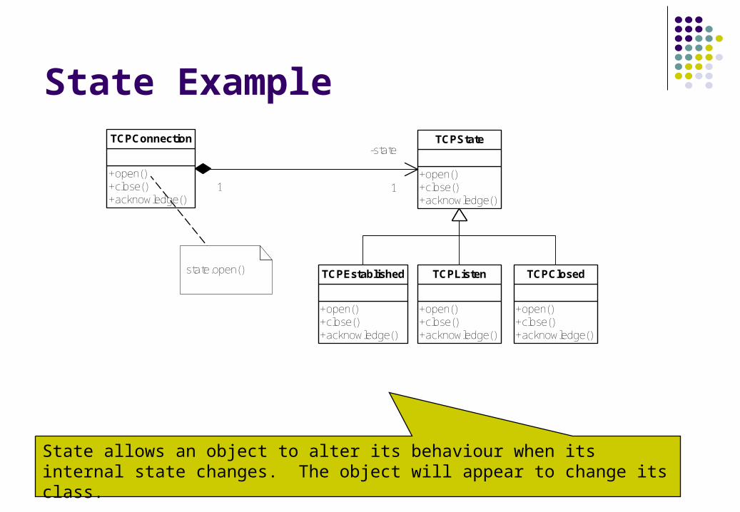
State allows an object to alter its behaviour when its internal state changes. The object will appear to change its class.
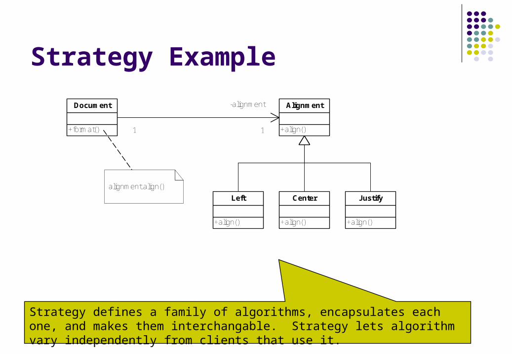
Strategy defines a family of algorithms, encapsulates each one, and makes them interchangable. Strategy lets algorithm vary independently from clients that use it.
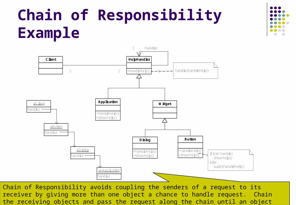
Chain of Responsibility Example
Client
+handleHelp()
HelpHandler
+handleHelp()+showHelp()
Application Widget
+handleHelp()+showHelp()
Dialog
+handleHelp()+showHelp()
Button
1 1 1
-handler1
handler.handleHelp()
if (can handle) showHelp()else super.handleHelp()
handler
aClient
handler
aButton
handler
aDialog
handler
anApplication
Chain of Responsibility avoids coupling the senders of a request to its receiver by giving more than one object a chance to handle request. Chain the receiving objects and pass the request along the chain until an object handles it.
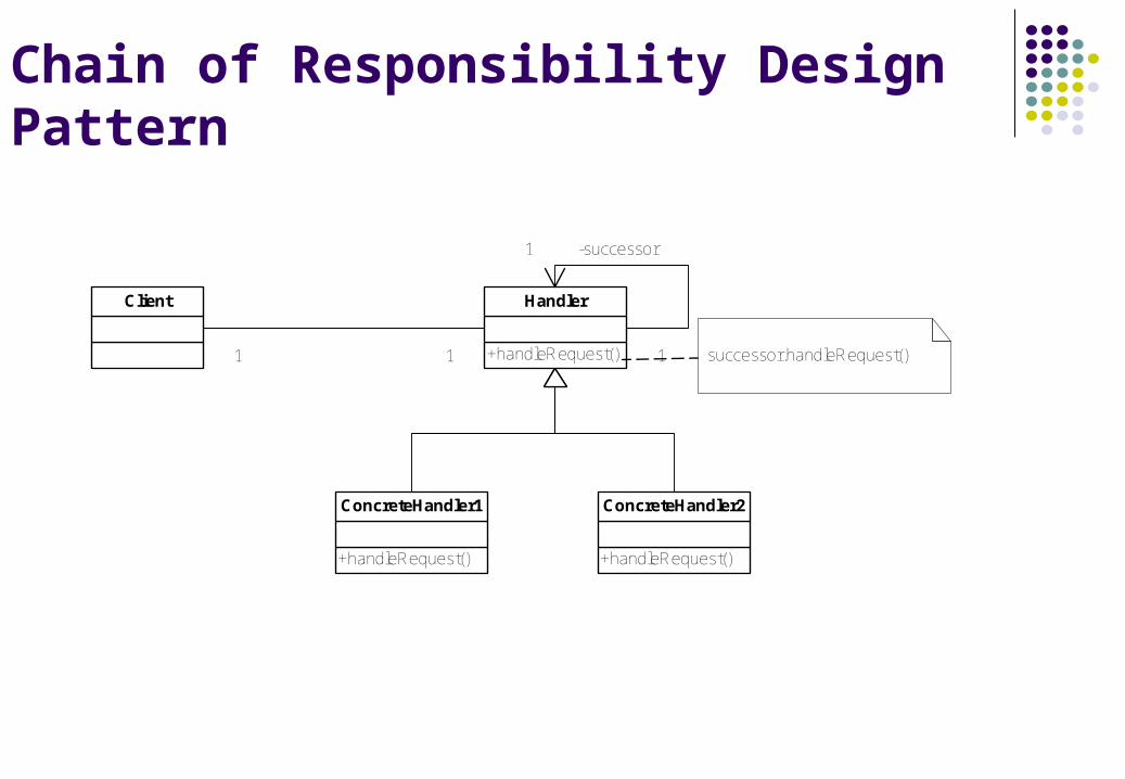
Chain of Responsibility Design Pattern
Client
+handleRequest()
Handler
+handleRequest()
ConcreteHandler1
+handleRequest()
ConcreteHandler2
1 1 1
-successor1
successor.handleRequest()
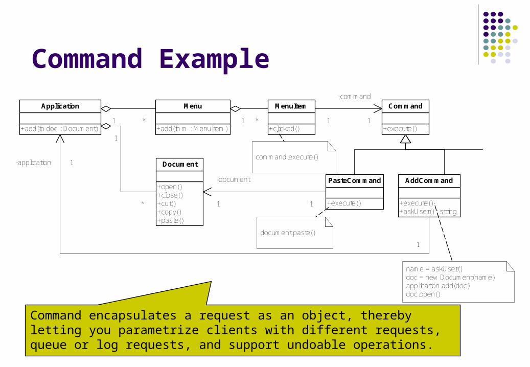
Command Example
+add(in doc : Document)
Application
+open()+close()+cut()+copy()+paste()
Document
+add(in m : MenuItem)
Menu
+clicked()
MenuItem
+execute()
Command
1 * 1 * 1
-command
1
+execute()
PasteCommand
1
* +execute()+askUser() : string
AddCommand-document
1 1
1
-application 1command.execute()
document.paste()
name = askUser()doc = new Document(name)application.add(doc)doc.open()
Command encapsulates a request as an object, thereby letting you parametrize clients with different requests, queue or log requests, and support undoable operations.
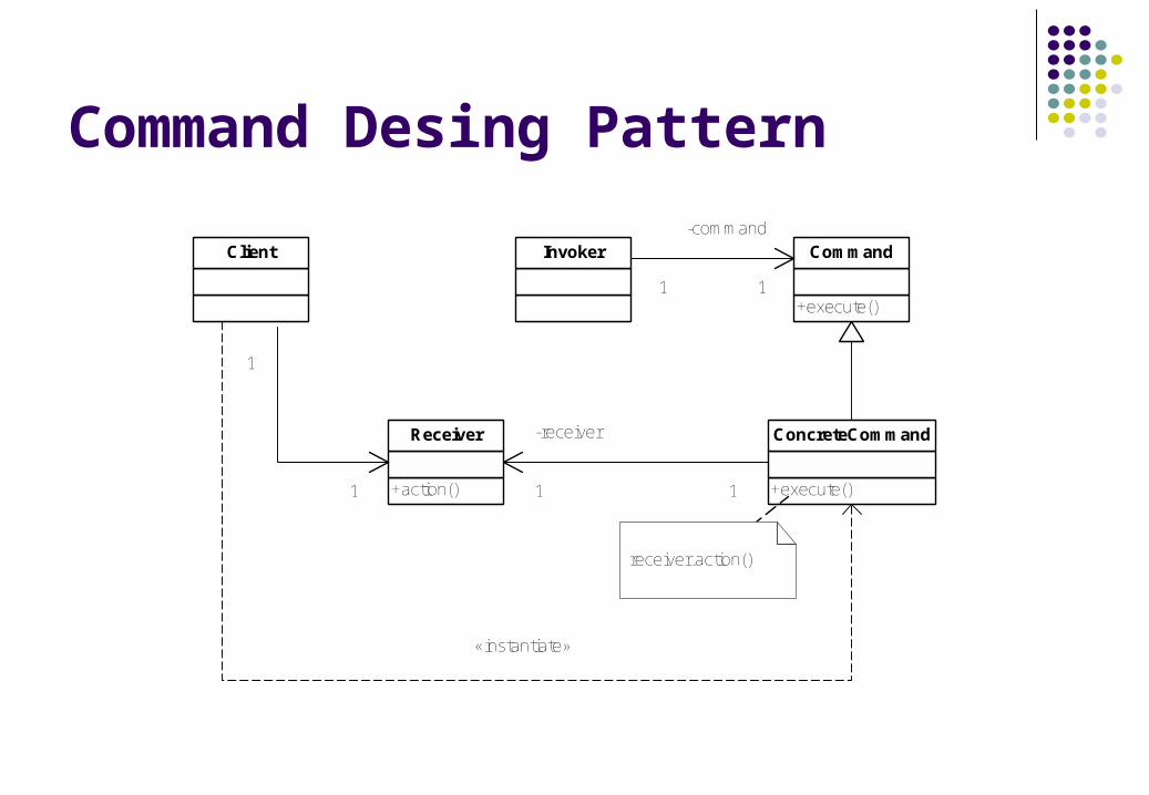
Command Desing Pattern
Client
+action()
Receiver
Invoker
+execute()
Command
1
-command
1
+execute()
ConcreteCommand
1
1
-receiver
1 1
receiver.action()
«instantiate»
Iterator Example
+createIterator() : Iterator
Collection Client
+first()+next()+isDone()
Iterator
+createIterator() : Iterator+append()+remove()+get(in index)
List
+createIterator() : Iterator+pop()+push()+top()
Stack
+first()+next()+isDone()
StackIterator
+first()+next()+isDone()
ListIterator
1 1 1 1
1 1
«instantiate»
11
«instantiate»
Iterator provides a way to access the elements of an aggregate object sequentially without exposing its underlying representation.
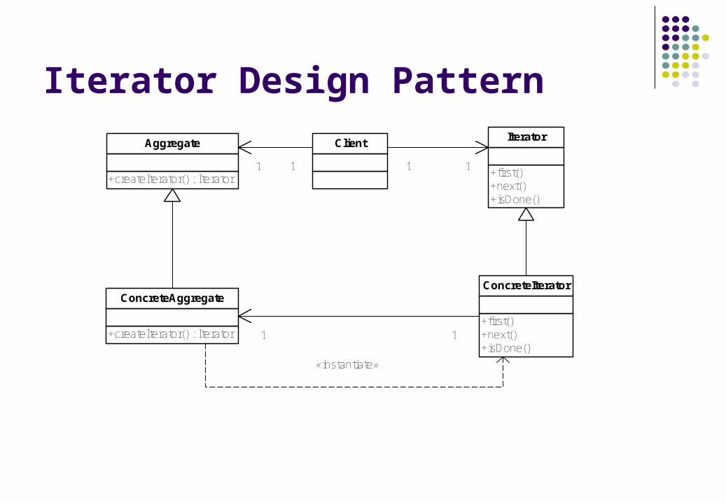
Iterator Design Pattern
+createIterator() : Iterator
Aggregate Client
+first()+next()+isDone()
Iterator
+createIterator() : Iterator
ConcreteAggregate
+first()+next()+isDone()
ConcreteIterator
1 1 1 1
1 1
«instantiate»
Observer Example
+attach(in o : Observer)+detach(in o : Observer)+notify()
Subject
+update()
Observer
1 -observer*
-subject
1 1
+getData() : float
-data[] : float
StockMarket
+update()+print(in data[])
TextArea
+update()+draw(in data[])
BarChart
for all observers observer.update()
data = subject.getData()print(data)
data = subject.getData()draw(data)
Observer defines a one-to-many dependency between objects so that when one object changes state, all its dependents are notified and updated automatically.
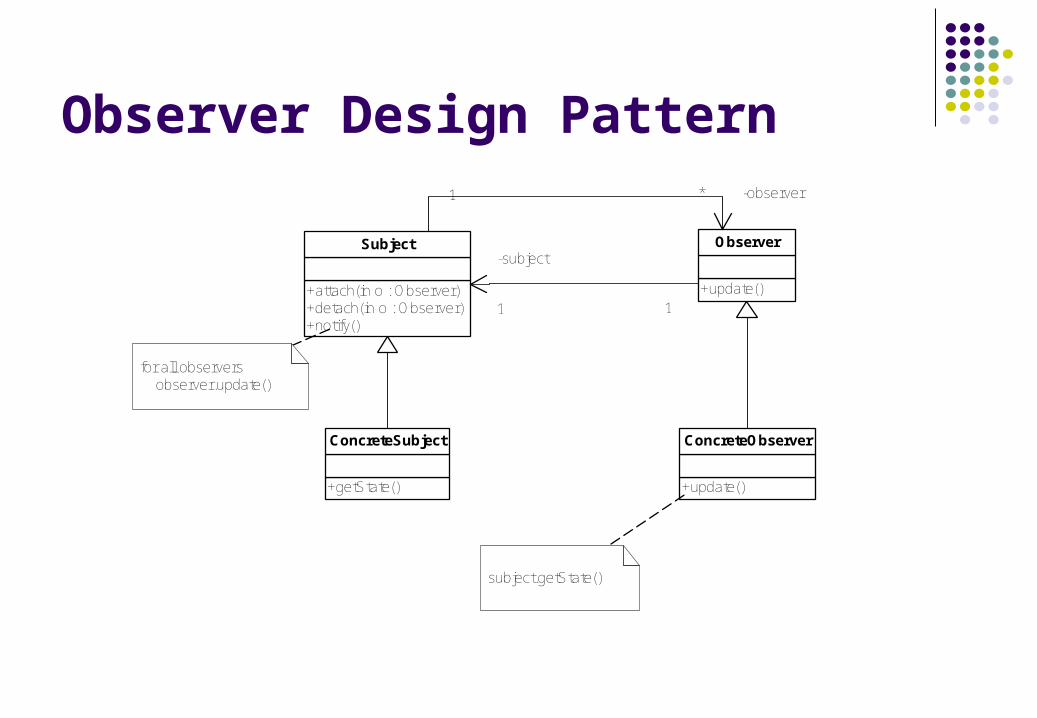
Observer Design Pattern
+attach(in o : Observer)+detach(in o : Observer)+notify()
Subject
+update()
Observer
1 -observer*
-subject
1 1
+getState()
ConcreteSubject
+update()
ConcreteObserver
for all observers observer.update()
subject.getState()
State Example
+open()+close()+acknowledge()
TCPConnection
+open()+close()+acknowledge()
TCPState
+open()+close()+acknowledge()
TCPEstablished
+open()+close()+acknowledge()
TCPListen
+open()+close()+acknowledge()
TCPClosed
1
-state
1
state.open()
State allows an object to alter its behaviour when its internal state changes. The object will appear to change its class.
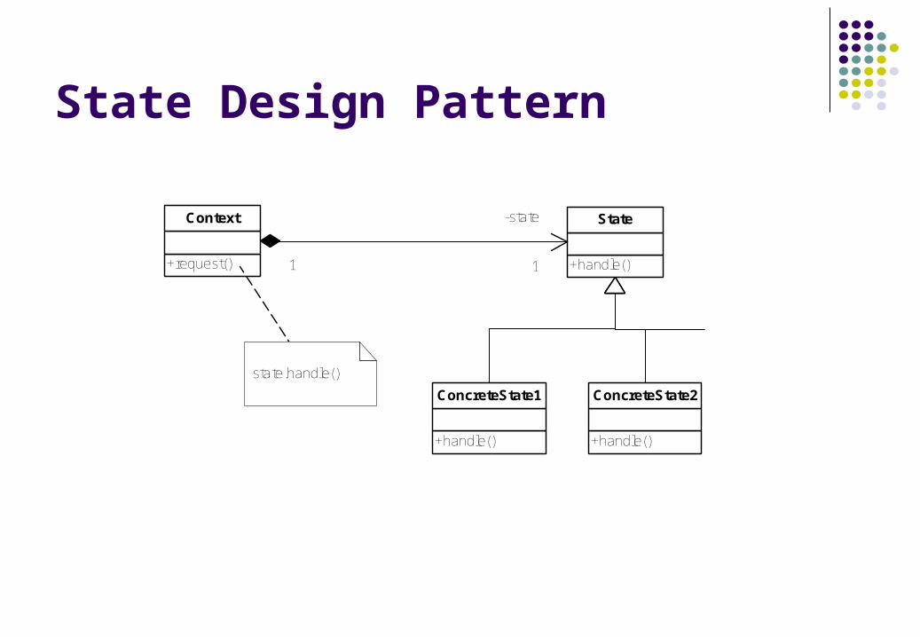
State Design Pattern
+request()
Context
+handle()
State
+handle()
ConcreteState1
+handle()
ConcreteState2
1
-state
1
state.handle()
Strategy Example
+format()
Document
+align()
Alignment
+align()
Left
+align()
Center
+align()
Justify
1
-alignment
1
alignment.align()
Strategy defines a family of algorithms, encapsulates each one, and makes them interchangable. Strategy lets algorithm vary independently from clients that use it.
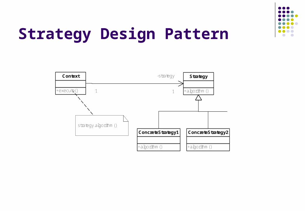
Strategy Design Pattern
+execute()
Context
+algorithm()
Strategy
+algorithm()
ConcreteStrategy1
+algorithm()
ConcreteStrategy2
1
-strategy
1
strategy.algorithm()
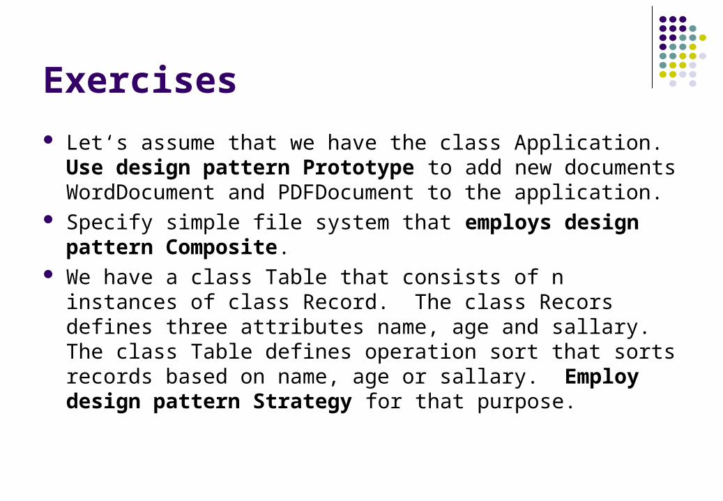
Exercises
Let‘s assume that we have the class Application. Use design pattern Prototype to add new documents WordDocument and PDFDocument to the application.
Specify simple file system that employs design pattern Composite.
We have a class Table that consists of n instances of class Record. The class Recors defines three attributes name, age and sallary. The class Table defines operation sort that sorts records based on name, age or sallary. Employ design pattern Strategy for that purpose.