Embed Size (px)
Citation preview
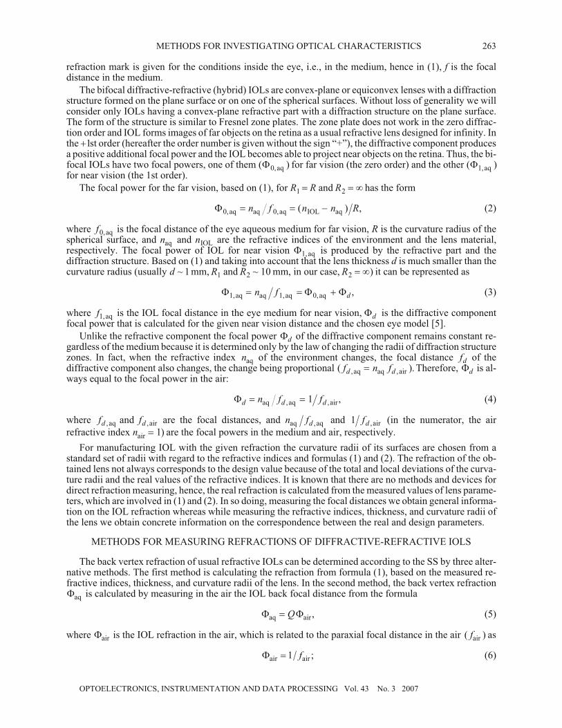
Methods for Investigating Optical Characteristics of Bifocal
Diffractive-Refractive Intraocular Lenses
G. A. Lenkova
Institute of Automation and Electrometry, Siberian Branch, Russian Academy of Sciences, Novosibirsk
E-mail: [email protected]
Received 23 June 2006
Abstract—Peculiarities of designing and determining the refraction (lens power) and the diffraction
efficiency of bifocal hybrid (diffractive-refractive) intraocular lenses (IOL)—implants—are considered.
Methods for designing the refractive IOL for near and far vision are analyzed and compared by means of
measuring the focal lengths in the air and medium. It is shown that in investigating the hybrid lenses it is
more convenient to estimate the conformity of the profile height with the designed value from the
relationship of intensities of the 1st and 2d diffraction orders in the air and of the zero and 1st orders in the
medium. Admissible errors of measurements and deviations of the hybrid IOL parameters are
determined and used for calculating the refraction and diffraction efficiency.
DOI: 10.3103/S8756699007030090
INTRODUCTION
Bifocal and multifocal intraocular lenses (IOL) that enable to see without glasses at any distance to ob-
jects find more and more application in eyesight recovery. The IOLs can act as refractive, diffractive, or
diffractive-refractive (hybrid) lenses. The latter are of particular interest because they enable to correct cor-
nea and spherical component aberrations, vary the relationship of intensities in images of near and far ob-
jects, decrease the lens thickness, etc. [1].
In IOL manufacturing, it is necessary to control that the optical characteristics should correspond to the
design parameters. International ISO/DIS 11979-2 Standard [2] and Russian R 52038-2003 State Standard
[3] (hereafter SS] are available for usual refractive IOLs. They set the optical characteristic requirements and
recommend methods for testing the accuracy of manufactured IOLs. Methods recommended by the SS are
only partially applicable to control of the diffractive-refractive IOLs because of their specificity. This paper
is aimed at considering possible methods for controlling the hybrid IOL parameters and at estimating
admissible measurement errors.
CALCULATING THE DIFFRACTIVE-REFRACTIVE IOL REFRACTIONS
The focal power (refraction) of the simplest two-component system which the refractive IOL refers to
can be represented as [4]
� � � � �� � � � � � ��
�
��
�
��
n f d n n nR R
d n n
1 1 2 1 2 2 2 1
1 2
2 11 1( )
( ),
2
2 1 2n R R
(1)
where � � �, ,1 2
and are the focal powers of lenses or components (lens surfaces), d is the distance between
the lenses or lens components, n1
and n2
are the refractive indices of the environment and the lens material,
respectively, and R R1 2
and are the curvature radii of the lens surfaces. Hereinafter we assume that f is the
back focal distance (usually denoted as f � in the geometric optics) and that the focal distances and the
curvature radii are given in millimeters and the focal powers, in diopters. We should note that the IOL
262
ISSN 8756-6990, Optoelectronics, Instrumentation and Data Processing, 2007, Vol. 43, No. 3, pp. 262–273. © Allerton Press Inc., 2007.
Original Russian Text © G.A. Lenkova, 2007, published in Avtometriya, 2007, Vol. 43, No. 3, pp. 85–99.
OPTICAL INFORMATION TECHNOLOGIES,
ELEMENTS, AND SYSTEMS
refraction mark is given for the conditions inside the eye, i.e., in the medium, hence in (1), f is the focal
distance in the medium.
The bifocal diffractive-refractive (hybrid) IOLs are convex-plane or equiconvex lenses with a diffraction
structure formed on the plane surface or on one of the spherical surfaces. Without loss of generality we will
consider only IOLs having a convex-plane refractive part with a diffraction structure on the plane surface.
The form of the structure is similar to Fresnel zone plates. The zone plate does not work in the zero diffrac-
tion order and IOL forms images of far objects on the retina as a usual refractive lens designed for infinity. In
the �1st order (hereafter the order number is given without the sign “+”), the diffractive component produces
a positive additional focal power and the IOL becomes able to project near objects on the retina. Thus, the bi-
focal IOLs have two focal powers, one of them ( )�0,aq
for far vision (the zero order) and the other ( )�1,aq
for near vision (the 1st order).
The focal power for the far vision, based on (1), for R R1
� and R2
� � has the form
�0,aq aq 0,aq IOL aq
� � �n f n n R( ) , (2)
where f0,aq
is the focal distance of the eye aqueous medium for far vision, R is the curvature radius of the
spherical surface, and naq
and nIOL
are the refractive indices of the environment and the lens material,
respectively. The focal power of IOL for near vision �1,aq
is produced by the refractive part and the
diffraction structure. Based on (1) and taking into account that the lens thickness d is much smaller than the
curvature radius (usually d ~ 1 mm, R1
and R2
10~ mm, in our case, R2
� �) it can be represented as
� � �1,aq aq 1,aq 0,aq
� � �n fd, (3)
where f1,aq
is the IOL focal distance in the eye medium for near vision, �d
is the diffractive component
focal power that is calculated for the given near vision distance and the chosen eye model [5].
Unlike the refractive component the focal power �d
of the diffractive component remains constant re-
gardless of the medium because it is determined only by the law of changing the radii of diffraction structure
zones. In fact, when the refractive index naq
of the environment changes, the focal distance fd
of the
diffractive component also changes, the change being proportional ( )., ,
f n fd daq aq air
� Therefore, �d
is al-
ways equal to the focal power in the air:
�d d d
n f f� �aq aq air, ,
,1 (4)
where f fd d, ,aq air
and are the focal distances, and n fdaq aq,
and 1 fd , air
(in the numerator, the air
refractive index nair
� 1) are the focal powers in the medium and air, respectively.
For manufacturing IOL with the given refraction the curvature radii of its surfaces are chosen from a
standard set of radii with regard to the refractive indices and formulas (1) and (2). The refraction of the ob-
tained lens not always corresponds to the design value because of the total and local deviations of the curva-
ture radii and the real values of the refractive indices. It is known that there are no methods and devices for
direct refraction measuring, hence, the real refraction is calculated from the measured values of lens parame-
ters, which are involved in (1) and (2). In so doing, measuring the focal distances we obtain general informa-
tion on the IOL refraction whereas while measuring the refractive indices, thickness, and curvature radii of
the lens we obtain concrete information on the correspondence between the real and design parameters.
METHODS FOR MEASURING REFRACTIONS OF DIFFRACTIVE-REFRACTIVE IOLS
The back vertex refraction of usual refractive IOLs can be determined according to the SS by three alter-
native methods. The first method is calculating the refraction from formula (1), based on the measured re-
fractive indices, thickness, and curvature radii of the lens. In the second method, the back vertex refraction
�aq
is calculated by measuring in the air the IOL back focal distance from the formula
� �aq air
� Q , (5)
where �air
is the IOL refraction in the air, which is related to the paraxial focal distance in the air ( )fair
as
�air air
� 1 f ; (6)
OPTOELECTRONICS, INSTRUMENTATION AND DATA PROCESSING Vol. 43 No. 3 2007
METHODS FOR INVESTIGATING OPTICAL CHARACTERISTICS 263

Q is the coefficient of conversion of the IOL refraction in the air to refraction in the medium; it is calculated
from the formula
Q � � �aq, nom air, nom
. (7)
Herein, �aq, nom
and �air, nom
are the IOL refractions in the conditions similar to the work inside the eye (in
situ) and in the air, both of them were calculated from (1) using the nominal parameters of the lens.
Paper [6] analyzed the relationship between the IOL optical characteristics in the air, aqueous liquid, and
cell. It was shown that for thin lenses like most present-day IOLs the refraction conversion coefficient de-
pends only on the refractive indices and can be written as
Q n n n� � �( ) ( ).IOL aq IOL
1 (8)
Substituting (6) and (8) into (5) yields
�aq IOL aq IOL air
� � �( ) ( )( ),n n n f1 1 (9)
where fair
is found by measuring or calculated from the formula
f R nair IOL
� �( ).1 (10)
In the third method, the IOL back vertex refraction is found by measuring the object enlargement. The
IOL focal distance ( )f is calculated from the formula
f F h h� ( ) ,target image
(11)
where htarget
and himage
are the linear sizes of the scale target and its image and F is the focal distance of the
collimator objective. Then we calculate �aq
from (2), or from (9) if f is measured in the air, assuming
f fair
� .
When determining the refraction by the second or third methods, the controlled IOL is placed behind the
collimator, the linear scale or test-object being at the focus. Then the focal distance (the distance from the
lens to the scale image) is measured by a microscope in the second method and the image size in the third.
The second method is most convenient and frequent because it does not require additional equipment for
measuring the curvature radii, linear size of the scale, and focal distance of the collimator objective. How-
ever, application of this method for testing bifocal diffractive-refractive IOLs in the form recommended by
the SS is impossible. The SS determines testing methods only for refractive IOLs.
Let us consider how we can change the second method for calculating the refraction �aq
, as applied to
the hybrid IOLs. It is known [1] that the microstructure of the hybrid IOL diffractive component is fabricated
as a sawtooth profile whose height is chosen such that the light intensities in the zero (far vision) and 1st
(near vision) diffraction orders in the medium of the eye are close or equal, and negligible in higher orders.
In the air, the phase delay on the structure increases and the light is primarily directed to the 1st and 2d dif-
fraction orders, the zero order being practically absent. Hence, while measuring in the air, it is impossible to
calculate the hybrid IOL refraction for the far vision from formula (9), and for the near vision we have to
consider the difference of refraction transformation for the diffractive and refractive components (formulas
(4) and (9)).
We can determine the refractions �0,aq
and �1,aq
for the far and near visions, respectively, by measure-
ments in the air in two ways. The first way is using the design value of the diffractive component focal power
�d
and the measured focal distance in the air in the 1st diffraction order ( ).f1,air
Then the formulas have the
form
� �0,aq 1,air
� �Q fd
( ),1 (12)
� � � �1,aq 0,aq 1,air
� � � � �d d
Q f Q( ) .1 (13)
OPTOELECTRONICS, INSTRUMENTATION AND DATA PROCESSING Vol. 43 No. 3 2007
264 LENKOVA

The other way is calculating the refractions from the measured values of focal distance in the air in the 1st
( )f1,air
and 2d ( )f2,air
orders, i.e., without using �d, from the formulas
�0,aq 1,air 2,air
� �Q f f( ),2 1 (14)
� � � �1,aq 0,aq 0,aq 2,air 1,air 2,air
� � � � � � �d
f f Q f( ) ( )1 1 1 � �( ) .1 2Q f1,air
(15)
In (12)–(15), Q is the conversion coefficient that is found from (8).
The third way is measuring the refractions for far and near visions in the medium if IOL is placed in a
cuvette filled with a salt solution (the SS allows distilled water). In this case, we observe the zero and 1st dif-
fraction orders. Paper [6] showed that refractions in the medium �0,aq
and �1,aq
) are equal to those behind
the cuvette �0,cuv
and �1,cuv
):
� �0,aq aq 0,aq 0,cuv 0,cuv
� � �n f f1 ;
(16)
� �1,aq aq 1,aq 1,cuv 1,cuv
� � �n f f1 ,
where f f0,aq 1,aq
and , f f0,cuv 1,cuv
and are the distances from the IOL to the focus in the medium and air
behind the cuvette, respectively. In the real conditions, the thickness of the aqueous layer and cuvette wall
are much smaller than the focal distance, hence after the light beam escapes the cuvette the distance from the
IOL to the focus in the air decreases with the medium refractive index naq
. Formula (16) follows from
relationships f n f0,aq aq 0,cuv
� and f n f1,aq aq 1,cuv
� . We might enter corrections for focus shifts caused
by the action of the medium layer and cuvette wall, but it is unnecessary if the focal distances are measured
by a microscope. In the latter case, the shifts of the images of focus and structure (or the lens vertex) occur
simultaneously in the same direction and by the same value.
The peculiarity of the third method is that �aq
is calculated simply as the inverse value of fcuv
expressed
in meters without entering the conversion coefficient. Thus, in this case, the measurement accuracy of the re-
fractive indices does not affect the result of measuring the refraction.
Contrary to the third method the refraction measurements according to the SS are carried out in the air, al-
though we showed above that measuring the IOL refraction using a cuvette has some advantages. The SS
recommends to place IOL in the eye model, i.e., in a cuvette filled with a salt solution in our case, only for in-
vestigating the image quality, that is, for measuring the resolution and the modulation transfer function.
The fourth and simpler method for refraction measurement, which is not considered in the SS, is as fol-
lows. A parallel laser beam illuminates the IOL, and the focal distance is measured behind the cuvette or in
the air as the difference between indications of the microscope longitudinal scale when it is targeted at the
lens surface and at the focused image of the point source (Fig. 1). This method has advantages over the de-
scribed methods. Firstly, it is not required to calibrate the scale. Secondly, the form of intensity distribution
in the focal plane (point spread function (PSF)) evidences either the presence or absence of spherical, astig-
OPTOELECTRONICS, INSTRUMENTATION AND DATA PROCESSING Vol. 43 No. 3 2007
METHODS FOR INVESTIGATING OPTICAL CHARACTERISTICS 265
Fig. 1. A system for measuring focal distances: 1, laser; 2, collimator; 3 and 4, deflecting mirrors; 5, cuvette filled with
distilled water and IOL; 6, microscope; 7, eye.

matic, or other aberrations. In addition, the PSF Fourier transform that is a modulation transfer function
(MTF) can show how the IOL transfers different spatial frequencies.
We should note that measurements in the air can cause problems because the IOL diffractive component
is calculated for the medium in such a manner that to correct the cornea and refractive component aberra-
tions in the 1st diffraction order for a standard wavelength. In the air, the correction conditions are violated
and spherical aberrations appear; they are most evident in the 2d diffraction order. Moreover, when measur-
ing in the white light we observe that the focal power of the IOL diffractive component depends on the wave-
length. In the 1st order, the chromatic aberrations of the diffractive and refractive components are mutually
compensated whereas in the 2d order, in the presence of spherical aberration they appreciably decrease the
image contrast and practically prevent measuring the focal distances in this order. Therefore, investigating
in the air in the white light the second method for calculating the refractions from (14) and (15), based on
measuring the focal distances in the 1st ( )f1,air
and 2d ( )f2,air
orders, i.e., without using �d
, can lead to er-
rors. In the monochromatic light, the aberrations in the 2d order are smaller and the second method is
possible.
MEASURING PARAXIAL FOCAL DISTANCE
The IOL focal power is calculated by geometric optics formulas (2), based on the paraxial focal distan-
ces f . For investigating the IOL quality of manufacturing the focal distance is measured as a distance from
the least-spreading spot to the back lens surface. To agree the measurement results with the calculation, we
have to enter corrections for the distance from the IOL surface to the principal back plane of IOL ( )�f SH1
� �
and from the paraxial focal point to the “best-focusing” point ( ),� �f S2
2� � i.e., to the plane where the mini-
mal spreading point is observed. The first correction is known from the geometric optics [7]:
� f SH
f n n d
n R1
� � �
�( )
.IOL aq
IOL
(17)
For a thin convex-plane lens for f n R n n� �aq IOL aq
( ) formula (17) is transformed into
�f S d n nH1
� � � ( ).aq IOL
(18)
For example, if d � 0.9 mm, then in the medium(naq
� 1.336 and nIOL
� 1.505), � f SH1
� � � 0.8 mm whereas
in the air ( ,n naq air
� � 1 nIOL
� 1.505), � f SH1
� � � 0.6 mm.
The second correction for IOL as a convex-plane lens can be calculated in a first approximation by (2.3)
from [6], taking into account that the minimal spreading spot is located half the value of longitudinal spheri-
cal aberration �S� (in [6], � �S fy
� � ) from the paraxial focus toward the lens:
� �f Sn n
n n
D
f
n n
n n
D
R2
3 2
2
2 3 2 2
22 2
4 1 4
2 2
4 1 4� � �
� �
�
�� �
�( ) ( ), (19)
where n n n�2 1
(n1
and n2
are the refractive indices of the environment and lens material), D and f are the
diameter and focal distance of the lens, and R is the curvature radius of the spherical surface. In the
conditions of the medium (n n1
� �aq
1.336) and for n n2
� �IOL
1.505 we obtain n � 1.1265 and
� �f S D R2
22 1 56 4� � � . . In the air ( )n n
11� �
airfor the same n
2we have n � 1.505 and
� �f S D R2
22 0 29 4� � � . . For example, for R � 8.24 mm ( f
aq� 65.14 mm and f
air� 16.32 mm) and
D � 4 5. mm (3 mm) for the medium � �f S2
2� � � 0.96 mm (0.43 mm) and for the air
� �f S2
2� � � 0.18 mm (0.08 mm), i.e., is about 5 times less. If the spherical aberration for the near vision
( )f1
is corrected at the expense of the diffractive component, then the second correction �f2
is calculated
only for f0
(far vision).
The calculation of �f2
from analytical formula (19) is convenient because it does not require special soft-
ware, nevertheless it is sufficiently accurate. The results of calculations by formula (19) and the ray-tracing
method for the medium differ by no more than 0.05 mm
OPTOELECTRONICS, INSTRUMENTATION AND DATA PROCESSING Vol. 43 No. 3 2007
266 LENKOVA

CORRECTION FOR FOCUS SHIFT DUE TO AQUEOUS LAYER AND CUVETTE WALL
In measuring the IOL characteristics in conditions similar to the work inside the eye, the lens is placed
into a cuvette filled with a salt solution (or distilled water), the cuvette simulates the eye model. In this case,
the measured distance from the lens to the focus behind the cuvette ( )fcuv.meas
is represented as
f n n f n d n n d dcuv.meas air aq cuv aq aq air cuv cuv a
� � � �( )( ) ( )q cuv
� d , (20)
where n naq cuv
, , and nair
are the refractive indices of the medium, wall, and air, respectively; daq
and dcuv
are
the thicknesses of the aqueous layer and wall; fcuv
is the focal distance behind the cuvette, assuming that the
thicknesses of the aqueous layer and wall are negligible. We can determine from (20) that
f f fcuv cuv.meas
� � �3, (21)
where �f3
is the focus shift caused by the aqueous layer and wall. For nair
� 1, from (20) and (21) we obtain
� f f f d n n d n n3
1 1� � � � � �cuv.meas cuv aq aq aq cuv cuv cuv
( ) ( ) . (22)
If the focal distance is measured by a microscope, the correction is not entered because the visible dis-
tance from the structure to the microscope changes simultaneously by the same value.
ERRORS IN DETERMINING REFRACTIONS OF DIFFRACTIVE-REFRACTIVE IOL
As was shown, the IOL refraction is determined by calculating by parameters or by measured focal dis-
tances. For evaluating how the discrepancy between the manufactured IOL parameters and the given values,
and also the accuracy of measuring the parameters and focal distances affect, the accuracy of determining
the refraction, we calculate the total differentials ��0,aq
and ��1,aq
from (2), (3), (5), (8), (9), and
(12)–(16):
�� �� � � �0,aq 1,aq IOL aq IOL aq
� � � � �( ) ( ) [( ) ] ,1 12
R n R n n n R R (2a), (3a)
�� � � � �0,aq 0,air 0,air 0,air
� �Q Q f2
, (5a)
� � �Q n n n n n� � � � �[( ) ( ) ] [ ( )] ,aq IOL IOL IOL aq
1 1 1 12
(8a)
�� � �0,aq 0,air 0,air
� � �2
Q f [ ( ) ( ) ] [ ( )]� � � �0,air aq IOL IOL 0,air IOL aq
n n n n n� � � �1 1 12
, (9a)
�� �� � � �0,aq 1,aq 0,air 1,air 1,air
� � �Q Q f f( ) ,2
(12a), (13a)
�� � � � �0,aq 0,air 1,air 1,air 2,air 2,a
� � �Q Q f f Q f f( ) ( )22 2
ir, (14a)
�� � � �1,aq 0,air 1,air 1,air 2,ai
� � � � �Q Q f f Q f[( ) ] [( )1 2 12
r 2,air
2] ,� f (15a)
�� �� �0,aq 0,cuv 0,cuv 0,cuv
� � � ( ) ,12
f f ( )16à�
�� �� �1,aq 1,cuv 1, cuv 1,cuv
� � � ( ) .12
f f ( )16à ��
OPTOELECTRONICS, INSTRUMENTATION AND DATA PROCESSING Vol. 43 No. 3 2007
METHODS FOR INVESTIGATING OPTICAL CHARACTERISTICS 267

In (5a) and (9a), the refraction accuracy for the refractive component of the hybrid IOL is denoted by
��0,aq
.This is the same as ��aq
for a usual refractive IOL based on (5) and (9). We should note that formu-
las for calculating the accuracy of giving and measuring the parameters, (2a), (3a), (12a) and (13a) obtained
by differentiating (2), (3), (12), and (13), respectively, have the same form. The explanation is that �d
is the
constant depending only on the law of changing the zone radii of the diffractive structure and independent of
the environment. Formulas ( )16à� and ( )16à �� were derived from (16) for far and near visions, respectively.
Note, in formulas (5a) and (12a)–(15a) the coefficients at �Q are the same although it follows from (5)
and (12)–(15) that their analytical form must be different. For simplifying the formulas, these and some
other coefficients were changed because in fact
� �0,air 0,air 1,air 1,air 2,air
� � � � �1 1 2 1f f f fd
( ) ( ) ( ).
Let us define formulas (2à)–(16a ��) and the tolerances for concrete initial IOL parameters:R � 8.24 mm,
�d
� 4.24 diopters, naq
� 1.336, and nIOL
�1.505. We calculate in addition the nominal values of the param-
eters that enter the formulas and are derivatives of these parameters: Q � 0.3347 (8), � �0,aq 0,cuv
� � 20.5
diopters (2), (16), � �1,aq 1,cuv
� � 24.74 diopters (3), (16), f0,air
� 16.32 mm (10), �0,air
� 61.25 diopters
(6), f1,air
� 15.27 mm ( ( )),fd1,air 0,air
� �1 � � f2,air
� 14.33 mm ( f2,air
�1 2( )),� �0,air
�d
f0,cuv
�
48.78 mm and f1,cuv
� 40.42 mm (16). Substituting the nominal parameter values into (2à)–(16a ��) in such a
manner that the accuracy of measuring �f and �R is expressed in millimeters and �� in diopters we obtain
�� �� � � �0,aq 1,aq IOL aq
� � � �121 36 121 36 2 49. . . ,n n R (2b), (3b)
�� � �0,aq 0,air
� �61 25 1 26. . ,Q f (5b)
� � �Q n n� �1 32 1 98. . ,IOL aq
(8b)
�� � � �0,aq 0,air IOL aq
� � � �1 26 80 78 121 18. . . ,f n n (9b)
�� �� � �0,aq 1,aq 1,air
� � �61 25 1 437. . ,Q f (12b), (13b)
�� � � �0,aq 1,air 2,air
� � �61 25 2 87 1 63. . . ,Q f f (14b)
�� � � �1,aq 1,air 2,air
� � �61 25 1 42 3 24. . . ,Q f f (15b)
�� �� �0,aq 0,cuv 0,cuv
� � �0 42. ,f ( )16b�
�� �� �1,aq 1,cuv 1,cuv
� � �0 61. .f (16b )��
Let us assume that we want to have ��0,aq
� 0.1 diopters, then according to (2b), (3b), (5b), and
(12b)–(15b) the curvature radius R and the conversion coefficient Q must be known or measured with the ac-
curacy �R � 0.04 mm and �Q � 0.0016. The required accuracy or admissible deviations in measuring the re-
fractive indices: �naq
�0.0008 ((2b), (8b), and (9b)), �nIOL
� 0.0008 (2b), �nIOL
� 0.0012 ((8b) and (9b)),
and in measuring the focal distances: � f0,air
� 0.08 mm ((5b) and (9b)), � f1,air
� 0.07 mm ((12b), (15b),
� f1,air
� 0.035 mm (14b), � f2,air
� 0.06 mm (14b), � f2,air
� 0.03 mm (15b), � f0,cuv
� 0.24 mm ( ),16b� and
� f1,cuv
� 0.17 mm ( ).16b�� These data show that in measuring the focal distances of IOL in the cuvette, the
admissible deviations are several times greater than in measuring in the air.
OPTOELECTRONICS, INSTRUMENTATION AND DATA PROCESSING Vol. 43 No. 3 2007
268 LENKOVA

It is clear that the coefficients in the formulas will change depending on the IOL refraction. We analyze
the degree of the change using formulas (2b) and (5b). For obtaining the refraction in the most essential re-
gion �0,aq
� 18–23 diopters (�0,air
� 53.7–68.7 diopters) the curvature radius of the lens spherical surface
has to be varied within R � 9.38–7.34 mm ( %)�12 and the coefficients at �n and �R, within 106.6–136.2
( %)�12 and 1.92–3.14 ( %)�24 . Assume ��0,aq
� 0.1 diopters, then � �n naq IOL
� � 0.0009–0.0007
( %)�12 and �R � 0.05–0.03 mm ( %).�25 For the chosen region of refractions the coefficient at �Q varies
within 53.78–68.72 ( %)�12 and the value of �Q, within 0.0019–0.0015 ( %)�12 . Calculations show that
for the chosen region of refractions the change of the coefficients in (2b)–(16 b )� and the tolerances do not
exceed 12–25%, i.e., change insignificantly. To conclude, we note that for calculating the diffraction with an
accuracy of 0.1 diopters the division value of the device in measuring refractive indices should be no more
than 0.0005, and in measuring the focal distances in the air and behind the cuvette, no more than
0.01–0.05 mm and 0.1 mm, respectively.
Measuring the focal distances, one should pay attention that it is necessary to enter corrections. Other-
wise the calculated refraction value will be greater by about 0.5–1.0 diopters because, depending on the
measurement conditions, these corrections can be about 0.6 mm (in the air) and 1 mm (in the medium). The
foregoing calculations evidence that the correction is important for measurements in the air.
METHODS AND ERRORS IN MEASURING DIFFRACTION EFFICIENCY OF HYBRID IOL
An important characteristic of hybrid IOL, besides the refraction, is diffraction efficiency in the zero and
1st diffraction orders. It is usually determined by the ratio of diffracted beam intensity to incident or trans-
mitted beam intensity. The intensity measurement system is shown in Fig. 2. In the general case, the effi-
ciency depends on the form and depth of the diffraction structure profile and on the reflection, absorption,
and scattering light losses. We assume that the light losses are small and the IOL diffraction structure is a
sawtooth structure. Then the intensity in the zero ( )I0
and nth ( )In
diffraction orders is represented as [8]
I0
2
2
2�
�
��
�
��
sin( ),
max
max
�
�(23)
In
n�
�
�
��
�
��
sin( )
( ),
max
max
�
� �
2
2 2
2
(24)
� � �max max
( ) ,� �2 h n nIOL aq
(25)
where �max
and hmax
are the maximal values of the phase delay and profile height within one zone of the
structure, n is the diffraction order, and � is the wavelength. Plots of the intensities are given in Fig. 3. It is
seen that in the medium with the profile height h � 1.61 �m the intensities of the zero and 1st orders are equal
(40.5% each), whereas in the air the zero order almost disappears. The explanation is that in the air, the phase
delay on the structure becomes greater and the light is redistributed and directed primarily to the 1st and 2d
orders (40.5% each). It is convenient to measure the efficiency in the air as well as the refraction in the 1st
and 2d orders, and then convert the results to the medium.
OPTOELECTRONICS, INSTRUMENTATION AND DATA PROCESSING Vol. 43 No. 3 2007
METHODS FOR INVESTIGATING OPTICAL CHARACTERISTICS 269
Fig. 2. A system for measuring diffraction efficiency: 1, cuvette with distilled water and IOL; 2, microobjective; 3,
photodiode with diaphragm; 4, microammeter.

Under experimental conditions while investigating the dependence of the diffraction efficiency on the
profile height hmax
it is problematic to take into account the effect of the light loss, including the higher-order
diffraction loss. Nevertheless, since this disadvantage is inherent in all orders, it can be prevented by analyz-
ing the mutual relationship of intensities in the operating orders. Based on (23)–(25), the relationships of in-
tensities of the zero and 1st �0 1,
), and also 1st and 2d ( ),
�1 2
diffraction orders, depending on the profile
height hmax
, have the form
�
�
0 1
0
1
2
,
max
max
( )
( )� �
� �
�
�
�
�
�
�
�
�
�
�I
I
h n n
h n n
IOL aq
IOL aq
�
h n nmax
( ),
IOL aq�
�
�
�
�
�
�
�
�
�
1
2
(26)
�
�
�1 2
1
2
2
,
max
max
( )
( )� �
� �
� �
�
�
�
�
�
�
�I
I
h n n
h n n
IOL aq
IOL aq �
2
. (27)
At the same time, by measuring or giving �0 1,
and �1 2,
we can find the profile height hmax
. From (26) and
(27) it follows that
h
n nmax
,( )( )
,�
� �
�
�0 1
1IOL aq
(28)
h
n nmax
,
,
( )
( )( )
.�
�
� �
� �
�
1 2
1 2
2
1IOL aq
(29)
Assuming that the intensities of the zero and 1st orders are equal, i.e., �0 1
1,
,� for � � 0.5461 �m
(nIOL
� 1.507, naq
� 1.3377, and n nIOL aq
� � 0.1693) from (28) we obtain hmax
� 1.61 �m and from (27)
�1 2,
� 8.98. This wavelength value is recommended by the Standard. In measuring the efficiency in the air,
the phase delay on the diffraction structure, according to (25), increases and approaches 2�. As a result, the
zero order becomes much smaller than the 1st order (,
�0 1
� 0.11). In these conditions, it is senseless to mea-
OPTOELECTRONICS, INSTRUMENTATION AND DATA PROCESSING Vol. 43 No. 3 2007
270 LENKOVA
(a)
(b)
Fig. 3. Plots of changing intensities in the zero (solid curves), 1st (dashed), and 2d (dash-dotted) diffraction orders: (a) in
the medium and (b) in the air versus profile height hmax for � � 0.5461 �m ((nIOL � 1.507 and naq � 1.3377).

sure �0 1,
. It is more convenient to estimate the correspondence of the profile height to the calculated value by
the relationship of the 1st- and 2d-order intensities (,
�1 2
� 1.04). If a suitable light source is not available, the
efficiency can be measured at other wavelengths, taking into account the dependence of the refractive in-
dices on the wavelength. Table 1 presents calculated values of �0 1,
and �1 2,
for measuring at the wavelengths
� � 0.5461, � � 0.6330 �m (He-Ne laser), and � � 0.5320 �m (solid-state laser) for the same profile height of
the diffraction structure (max
h � 1.61 �m). It is seen that the intensity relationships depends greatly on the
wavelength.
Plots of changing �0 1,
in the medium (26) and �1 2,
in the air (27) for the wavelength � � 0.5461 �m are
depicted in Fig. 4. It is seen that insignificant deviations of hmax
from the calculated value have a stronger ef-
fect on �1 2,
in the air than on �0 1,
in the medium. The relationship of the beam intensities behind the cuvette
remains equal to �0 1,
because it is formed before escaping the cuvette and depends only on the phase profile
height in the medium.
We find analytically the degree of effect of the deviations �hmax
, and �nIOL
and �naq
on the changes of
the relative efficiencies ��0 1,
and ��1 2,
near the calculated value of the profile depth hmax
� 1.61 �m. Thus,
let us differentiate (26) and (27):
� � � ��0 1 0 1, , max max
[ ( ) (� � � � � �a h h n n n n n nIOL IOL aq aq IOL aq
)], (30)
� � � ��1 2 1 2, , max max
[ ( ) (� � � � �a h h n n n n n nIOL IOL aq aq IOL aq
)], (31)
where
ah n n
a
h n n
0 1
0 1
1 2
1 22 2
,
,
max
,
, max
( );
(
��
�
�� � � �
IOL aq
IOL aq)
[ ( )]
.
max� � �h n n
IOL aq
2(32)
OPTOELECTRONICS, INSTRUMENTATION AND DATA PROCESSING Vol. 43 No. 3 2007
METHODS FOR INVESTIGATING OPTICAL CHARACTERISTICS 271
Table 1
Parameters Medium Air
�,�m nIOL
naq
n nIOL aq
� �0 1,
�1 2,
�0 1,
�1 2,
0.5461 1.5070 1.3377 0.1693 1.00 8.98 0.11 1.04
0.5320 1,5077 1.3387 0.1690 0.91 9.28 0.12 0.75
0.6330 1.5030 1.3348 0.1682 1.79 7.55 0.05 6.65
Fig. 4. Changes of the relative intensities �0 1, in the medium(solid curve) and �1 2, in the air (dash-dotted) plotted versus
profile height hmax for the wavelength � � 0.5461 �m (nIOL � 1.507 and naq � 1.3377).

Table 2 represents calculated values of a a0 1 1 2, ,
and from (30) and (31) for three wavelengths in measur-
ing in the medium and air, and Tables 3 and 4 contain values of the coefficients at � � �h n nmax
, ,IOL aq
, and
tolerances � � �h n nmax
, ,IOL aq
in measuring the relative intensities ��0 1,
in the medium and ��1 2,
in the air
with an accuracy of 0.1.
Table 3 shows that for measuring in the medium, �hmax
~ 0.03–0.04 �m and � �n nIOL aq
� ~ 0.003–0.004
if ��0 1,
� 0.1. In the air (see Table 4) for ��1 2,
� 0.1for the first two wavelengths the values of �hmax
are
approximately two times less and �nIOL
are approximately the same; for � � 0.6330 �m, �hmax
and �nIOL
are 13 and 5 times less than for the medium for ��0 1,
� 0.1.
CONCLUSIONS
We have shown that the methods for calculating the refraction by measuring the IOL focal distance in the
air, recommended by the SS for refractive IOL, are inapplicable to hybrid lenses because the zero diffraction
order that ensures far vision is practically absent in the air. The possibilities and peculiarities of calculating
the refraction for near and far vision by measuring focal distances in the 1st and 2d orders in the air and in the
zero and 1st orders in the medium have been considered. Admissible errors of IOL parameters used for cal-
culating the refraction were analyzed. For calculating the refraction with an accuracy of 0.1 diopters the cur-
vature radius and conversion coefficient Q have to be known or measured with an accuracy of 0.04 mm and
0.0016, respectively, the refractive index accuracy should be equal to ~ . ,0 0005 and the focal distance accu-
racy should be 0.01–0.05 mm in measuring in the air and 0.1 mm behind the cuvette. It has been shown that
in the region of the greatest demand, for refractions (18–23 diopters) the tolerances for the accuracy of mea-
OPTOELECTRONICS, INSTRUMENTATION AND DATA PROCESSING Vol. 43 No. 3 2007
272 LENKOVA
Table 2
�, �m
Medium Air
n nIOL aq
� a0 1,
a1 2,
nIOL
� 1 a0 1,
a1 2,
0.5461 0.1693 4.02 11.92 0.5070 0.44 12.47
0.5320 0.1690 3.74 13.06 0.5077 0.45 9.23
0.6330 0.1682 6.25 7.18 0.5030 0.34 84.58
Table 3
�, �m
Medium ��0 1,
� 0.1)
Coefficients Tolerances
n nIOL aq
� a h0 1, max
a n n0 1,
( )IOL aq
� �hmax
, �m � �n nIOL aq
,
0.5461 0.1693 2.50 23.74 0.040 0.0042
0.5320 0.1690 2.32 22.13 0.043 0.0045
0.6330 0.1682 3.88 37.16 0.026 0.0027
Table 4
�,�m
Air ��1 2,
� 0.1)
Coefficients Tolerances
nIOL
� 1 a h1 2, max
a n1 2
1,
( )IOL
� �hmax
, �m �nIOL
0.5461 0.5070 7.75 24.60 0.013 0.0040
0.5320 0.5077 5.74 18.20 0.017 0.0055
0.6330 0.5030 52.53 168.15 0.002 0.0006

suring or giving the parameters change depending on the refraction value by no more than 12–25%. Com-
parison of the efficiency of hybrid lenses in the air and medium shows that in the air, it is more convenient to
estimate the correspondence of the profile height to the calculated value by the relationship of intensities in
the 1st and 2d orders. For obtaining the relative intensities with a 0.1 accuracy the deviations of the diffrac-
tion structure profile depth and refractive indices from the given values in the medium should be less or
equal to 0.03–0.04 �m and 0.003–0.004 �m, respectively. In the air, the tolerances for these deviations de-
crease several times (2.5–13), depending on the parameters and wavelength. We should note that the effect
of each parameter is estimated separately. The total IOL refraction deviation can exceed 0.1 diopter but ac-
cording to the SS it should not exceed 0.4 diopter.
The obtained relationships and inferences were used in investigating the accuracy of manufacturing
diffractive-refractive IOLs on special test benches and a setup for measuring optical characteristics of eyes
in the IAiE SB RAS (Novosibirsk, Russia). A pilot batch of MIOL-Akkord diffractive-refractive IOLs was
fabricated by IntraOL (Novosibirsk) and Reper-NN (Nizhni Novgorod) enterprises in 2005. The lenses were
based on a diffraction structure matrix developed in the IAiE SB RAS. The MIOL-Akkord lenses have run
clinical trials in the Novosibirsk and other departments of FGU MNTK “Eye Microsurgery”. After implant-
ing, patients have a good far vision and can read without glasses. Results of the trials were sent to the Minis-
try of Health and Social Development for licensing the MIOL-Akkord lenses in medical practice.
ACKNOWLEDGMENTS
This research was supported by the Russian Foundation for Basic Research, grant no. 06-08-00541.
The author is grateful to V. P. Koronkevich for fruitful discussions and A. N. Remennoi for his attention.
REFERENCES
1. V. P. Koronkevich, G. A. Lenkova, I. A. Iskakov, et al., “Bifocal Diffractive-Refractive Intraocular Lens,”
Avtometriya, No. 6, 26 (1997) [Optoelectr., Instrum. Data Process., No. 6, 26 (1997)].
2. ISO/DIS 11979-2, Optics and Optical Instruments—Intraocular Lenses. Pt. 2: Optical Properties and their
Methods, 1996.
3. GOST R 52038-2003 (ISO11979-2-99), Ocular Implants. Intraocular Lenses, Part 2. Optical Properties and
Methods of Trials (Gosstandart, Moscow, Russia) [in Russian].
4. M. I. Apenko and A. S. Dubovik, Applied Optics (Nauka, Moscow, 1982) [in Russian].
5. G. A. Lenkova and M. M. Myznik, “Investigation of Dependence of the Image Quality of a Schematic Eye with a
Hybrid Bifocal Intraocular Lens on the Diameter of the Pupil,” Avtometriya, No. 3, 61 (2002) [Optoelectr.
Instrum. Data Process., No. 3, 50 (2002)].
6. G. A. Lenkova, “Optical Characteristics of Intraocular Lenses in Air, Water, and Cell,” Avtometriya, No. 3, 35
(1997) [Optoelectr. Instrum. Data Process., No. 3, 32 (1997)].
7. B. N. Begunov, Geometric Optics (Mosk. Un., Moscow, 1961) [in Russian].
8. G. A. Lenkova, “The Effect of Phase Profile Depth on Intensity Distribution in Diffraction Orders of a Bifocal
Element,” Avtometriya, No. 5, 16 (1995) [Optoelectr. Instrum. Data Process., No. 5, 15 (1995].
OPTOELECTRONICS, INSTRUMENTATION AND DATA PROCESSING Vol. 43 No. 3 2007
METHODS FOR INVESTIGATING OPTICAL CHARACTERISTICS 273