Embed Size (px)
Citation preview
Copyright © 2014 Kinectrics Inc. All rights reserved. Page 1
life cycle management solutions
Methods for Improving Ground Resistance/Transient
Ground Impedance of Transmission Structures
Dr. Emanuel Petrache
Kinectrics Inc., Canada
CEATI Project: T113700 #3227
2014 IEEE PES Transmission & Distribution
Conference & Exposition
Chicago, April 14-17
Copyright © 2014 Kinectrics Inc. All rights reserved. Page 2
life cycle management solutions
Background
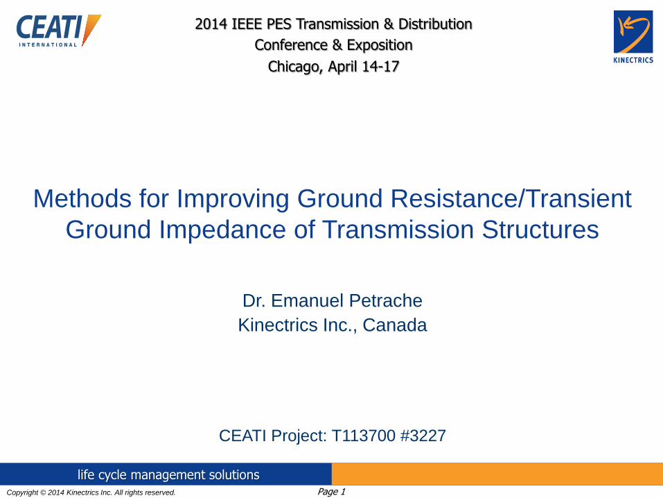
Previous Work: CEATI Report T093700-3227 “Methods for Improving Ground Resistance of Transmission Structures – Phase I”
Reviews methods for improving the ground resistance of transmission line structures
A simplified equation, based on shape and fill factors, is proposed to calculate the resistance of any electrode.
The approach is used to both visualize and calculate the effectiveness of possible electrode installations.
The report offers an illustrated guide for of possible ground electrode installations for difficult soil: single-pole, H-frame, four-leg steel lattice, and guyed towers.

Copyright © 2014 Kinectrics Inc. All rights reserved. Page 3
life cycle management solutions
Single-Pole Structures: Possible Ground
Electrode Installations for Difficult Soil
Base Case
Short Rod Nearby, distance s from edge, length L
Long Rod Nearby, length below foundation L
Single Horizontal Wire, length L, buried at depth d
Two Wires, 180º, length L, depth d
Four Wires, 90º length L, depth d
Four Wires, 90° to 10 m then Bent 45° along ROW, length L, depth d
Resistance of Cylindrical Foundation Electrode with Radial Counterpoise, comparing ChizWhiz Model (Trench
area) with Reference Calculations. Scale result by Observed Resistivity / 1000 m
Copyright © 2014 Kinectrics Inc. All rights reserved. Page 4
life cycle management solutions
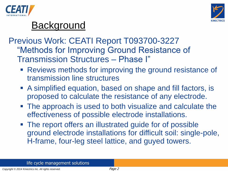
Calculated Resistance of One, Two, Three or Four Counterpoise in line with Two-Pole Tower Leg with = 1000 m. Scale result by
(Observed Resistivity / 1000 m)
H-frame Structures: Possible Ground Electrode
Installations for Difficult Soil
Copyright © 2014 Kinectrics Inc. All rights reserved. Page 5
life cycle management solutions
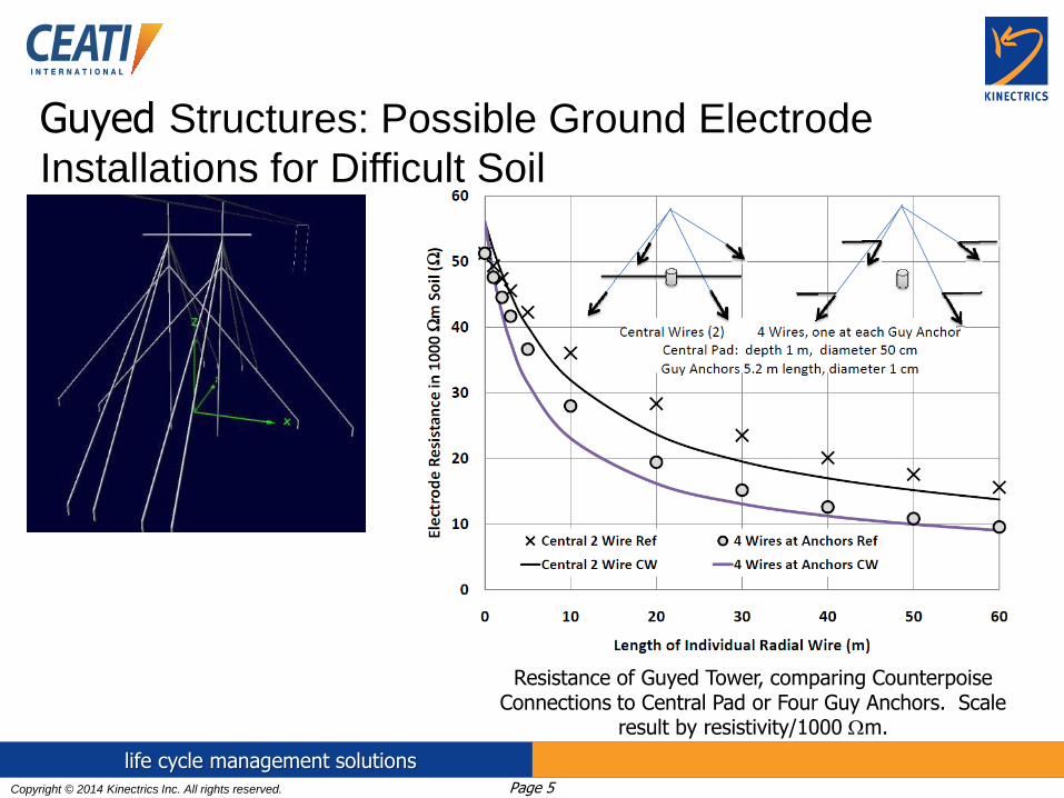
Resistance of Guyed Tower, comparing Counterpoise Connections to Central Pad or Four Guy Anchors. Scale
result by resistivity/1000 m.
Guyed Structures: Possible Ground Electrode
Installations for Difficult Soil
Copyright © 2014 Kinectrics Inc. All rights reserved. Page 6
life cycle management solutions
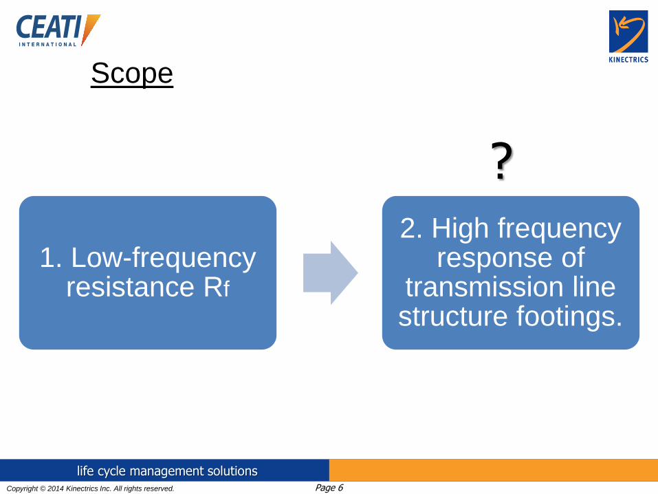
Scope
1. Low-frequency resistance Rf
2. High frequency response of
transmission line structure footings.
?

Copyright © 2014 Kinectrics Inc. All rights reserved. Page 7
life cycle management solutions
Scope
• compared a reference low frequency approach with two different high frequency models for the ground resistance/transient ground impedance of transmission structures.
• analyzed and the effectives of various ground improvement methods evaluated in a range of uniform soil resistivity values covering the most commonly encountered difficult soil conditions.

Copyright © 2014 Kinectrics Inc. All rights reserved. Page 8
life cycle management solutions
Configurations modeled
Method for improving ground resistance
Structure Type
Single-Pole
structure (Steel
Pole)
H-Frame
structure with
and without guys
Lattice structure
on four legs
1 no treatment var soil resistivities var soil resistivities var soil resistivities
2 radial counterpoise var soil resistivities var soil resistivities var soil resistivities
3 loop counterpoise var soil resistivities var soil resistivities var soil resistivities
4
continuous
counterpoise var soil resistivities var soil resistivities var soil resistivities
5 vertical well var soil resistivities var soil resistivities var soil resistivities
- Uniform soil resistivity values in the simulations [Ωm]: 300, 1000,
2000, and 5000.
- Relative permittivity of the soil: 10

Copyright © 2014 Kinectrics Inc. All rights reserved. Page 9
life cycle management solutions
Software packages
• Low-frequency resistance of the electrodes computed with
the standard CDEGS MALTZ package.
• High-frequency impedance computed with the CDEGS
HIFREQ module, and with NEC-4.
• CDEGS software used to study single-layer versus two and
multi-layer soil results.

Copyright © 2014 Kinectrics Inc. All rights reserved. Page 10
life cycle management solutions
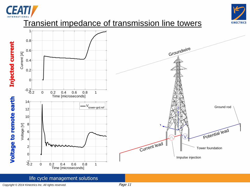
Modeling methodology
Numerical equivalent of the EPRI ZedMeter® test
method:
it simulates a lightning-like impulse injection into the
transmission structure base and measures the resulting
potential rise relative to a remote ground
Copyright © 2014 Kinectrics Inc. All rights reserved. Page 11
life cycle management solutions
-0.2 0 0.2 0.4 0.6 0.8 1-0.2
0
0.2
0.4
0.6
0.8
1
Time [microseconds]
Cu
rre
nt
[A]
Transient impedance of transmission line towers
Groundwire
Current lead
Potential lead
V
Impulse injection
Tower foundation
Ground rod
-0.2 0 0.2 0.4 0.6 0.8 1-2
0
2
4
6
8
10
12
14
Time [microseconds]
Voltage [
V]
Vtower-grd.ref
Inje
cte
d c
urr
en
t
Vo
lta
ge
to
re
mo
te e
art
h
Copyright © 2014 Kinectrics Inc. All rights reserved. Page 12
life cycle management solutions
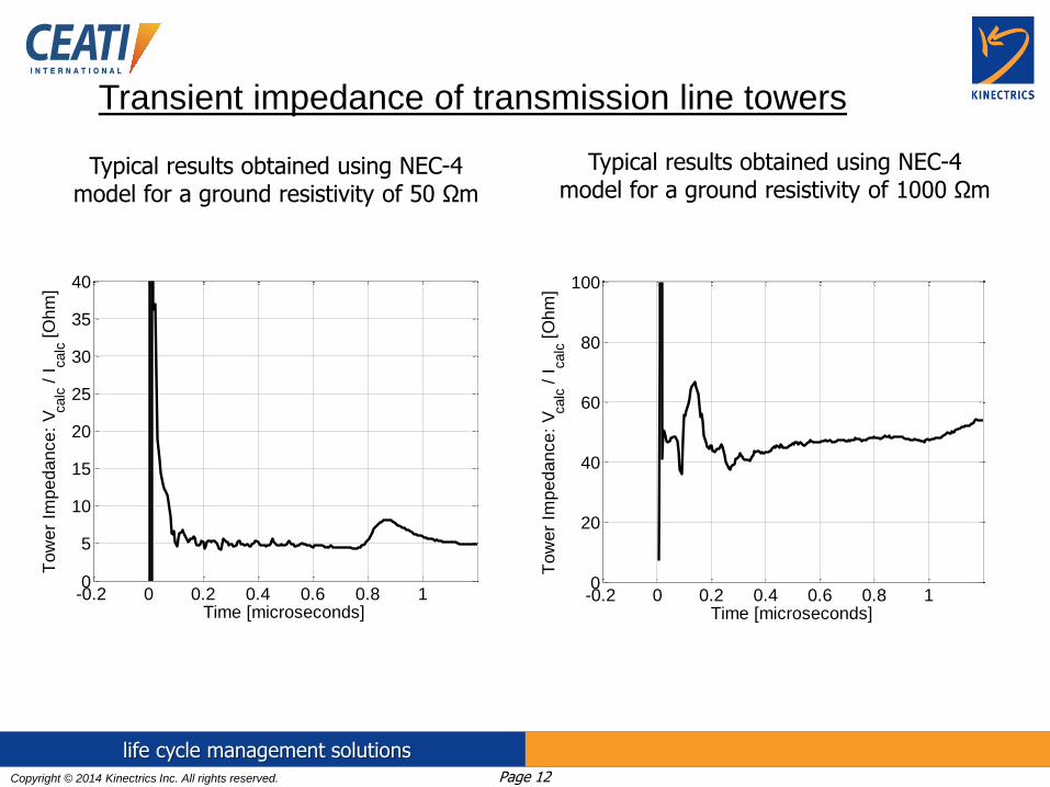
Typical results obtained using NEC-4 model for a ground resistivity of 50 Ωm
-0.2 0 0.2 0.4 0.6 0.8 10
5
10
15
20
25
30
35
40
Time [microseconds]
Tow
er
Impedance:
Vcalc /
Icalc [
Ohm
]
Typical results obtained using NEC-4 model for a ground resistivity of 1000 Ωm
-0.2 0 0.2 0.4 0.6 0.8 10
20
40
60
80
100
Time [microseconds]
To
we
r Im
pe
da
nce
: V
calc /
Icalc [
Oh
m]
Transient impedance of transmission line towers

Copyright © 2014 Kinectrics Inc. All rights reserved. Page 13
life cycle management solutions
Current injection lead;
length = 150 m
Potential lead;
length = 100 m
Adjacent structure
2 x OHGW
span length = 200 m
H-frame structure model; height = 18.4 m
Adjacent structure
H-frame guyed structure reference case (no treatment)
Example: H-frame/guyed structure

Copyright © 2014 Kinectrics Inc. All rights reserved. Page 14
life cycle management solutions
a) 2 x 12 m radial counterpoise 12 m
b) 4 x 30 m radial counterpoise
4 x radial counterpoise, each 30 m long, installed at a depth of 0.5 m
2 x radial counterpoise, each 12 m long, installed at a depth of 0.5 m
H-frame guyed structure radial counterpoise treatment
Example: H-frame/guyed structure

Copyright © 2014 Kinectrics Inc. All rights reserved. Page 15
life cycle management solutions
Loop counterpoise total length 30.7 m, installed at a depth of 0.5 m
H-frame guyed structure loop counterpoise treatment
Example: H-frame/guyed structure

Copyright © 2014 Kinectrics Inc. All rights reserved. Page 16
life cycle management solutions
Continuous counterpoise installed at a depth of 0.5 m and an offset of 7.5 m from the center of the ROW
H-frame guyed structure continuous counterpoise treatment
Example: H-frame/guyed structure

Copyright © 2014 Kinectrics Inc. All rights reserved. Page 17
life cycle management solutions
Vertical 152 mm dia. well 60 m deep
current injection lead; length = 150 m
potential lead; length = 100 m
H-frame guyed structure vertical well treatment
Example: H-frame/guyed structure
Copyright © 2014 Kinectrics Inc. All rights reserved. Page 18
life cycle management solutions
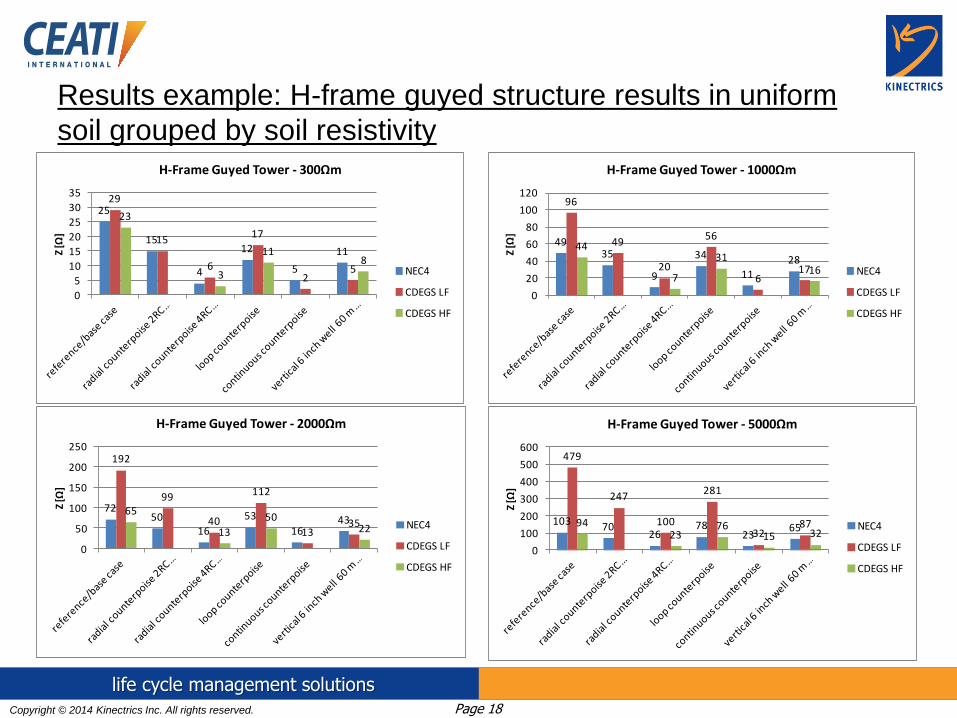
Results example: H-frame guyed structure results in uniform
soil grouped by soil resistivity
25
15
4
12
5
11
29
15
6
17
25
23
3
118
0
5
10
15
20
25
30
35
Z [Ω
]
H-Frame Guyed Tower - 300Ωm
NEC4
CDEGS LF
CDEGS HF
4935
9
34
11
28
96
49
20
56
617
44
7
3116
0
20
40
60
80
100
120
Z [Ω
]
H-Frame Guyed Tower - 1000Ωm
NEC4
CDEGS LF
CDEGS HF
7250
16
53
1643
192
99
40
112
1335
65
13
5022
0
50
100
150
200
250
Z [Ω
]
H-Frame Guyed Tower - 2000Ωm
NEC4
CDEGS LF
CDEGS HF
103 7026
7823
65
479
247
100
281
328794
2376
15 32
0
100
200
300
400
500
600
Z [Ω
]
H-Frame Guyed Tower - 5000Ωm
NEC4
CDEGS LF
CDEGS HF
Copyright © 2014 Kinectrics Inc. All rights reserved. Page 19
life cycle management solutions
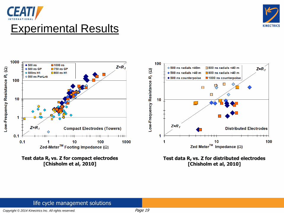
Experimental Results
Test data Rf vs. Z for compact electrodes [Chisholm et al, 2010]
Test data Rf vs. Z for distributed electrodes [Chisholm et al, 2010]

Copyright © 2014 Kinectrics Inc. All rights reserved. Page 20
life cycle management solutions
• Transient impedance Z has a non-linear variation
with the soil resistivity. In other words, the degree of
improvement offered by the various methods of
treatment, judged from the transient impedance point
of view, varies with the soil resistivity.
• The crossover from low-frequency to high-frequency
impedance was described using an impulse
coefficient, that was typically less than unity for
compact electrodes and greater than unity for
distributed electrodes, up to certain limits of length
and resistivity.
Conclusions
Copyright © 2014 Kinectrics Inc. All rights reserved. Page 21
life cycle management solutions
• In most of the cases, the results obtained with both
programs are showing a decrease of calculated impulse
coefficient with the increase of soil resistivity. This
indicates that the electrode is becoming more efficient in
dissipating the lightning currents with the increase of the
soil resistivity compared to what the low-resistance may
suggest.
• The two different high frequency models were in close
agreement for some electrodes but tended to differ on the
degree of reduction of high-frequency impedance for
continuous counterpoise and deep-well electrodes.
Conclusions
Copyright © 2014 Kinectrics Inc. All rights reserved. Page 22
life cycle management solutions
• Best practices for improving the ground
resistance/transient response include the use of four
radial counterpoise. For the lattice structure case the
CDEGS HIFREQ and NEC-4 models did not agree
on the relative ranking of loop electrodes, four radial
counterpoise and continuous counterpoise, and this
discrepancy should be addressed by field tests.
Conclusions
Copyright © 2014 Kinectrics Inc. All rights reserved. Page 23
life cycle management solutions
• A number of areas of interest for future research work
include the investigation of the ground electrical
parameters, their frequency-dependence, and the impact on
the calculated transient response of the transmission line
structures, and a comprehensive testing program that will
establish experimental values of impulse coefficient for
transmission line structures and wind turbines.
Future work

Copyright © 2014 Kinectrics Inc. All rights reserved. Page 24
life cycle management solutions
Possible implementation of soil-parameter frequency
dependence using commercial software packages
CM and CE comment cards
GW cards define model geometry
End geometry input data:
Ground parameters card:
Set frequencies card:
CM Sim# I1-C-L01-GR-GW-50
CM Number of Frequency Loops: : 512 (Fmax: 100MHz)
CM --- Do not delete the above comment lines ---
CM Start of geometry
CE
CM Impulse lead
GW1,6,4.039,4.039,0.1,4.039,7.039,0.1,1.8e-3
....
....
....
GE -1 0
GN 2 0 0 0 10 0.02
IS 0 1 0 0 3 1.0E-10 2.5E-3
IS 0 2 0 0 3 1.0E-10 2.5E-3
IS 0 5 0 0 3 1.0E-10 2.5E-3
IS 0 6 0 0 3 1.0E-10 2.5E-3
LD 0 1 3 3 50 0 0
LD 0 5 1 1 1.0E+07 0 0
FR 0 512 0 0 0.1953125 0.1953125
EX 0 1 3 00 1.0000 0.00000
XQ 0
EN
EPSR(f), SIG(f)
the expressions
derived from
experimental
results and
published by
Visacro et al
Example: NEC-4

Copyright © 2014 Kinectrics Inc. All rights reserved. Page 25
life cycle management solutions
Thank you!