Embed Size (px)
Citation preview
METHODOLOGY TO CREATE
ANIMATIONS USING
OPEN SOURCE REPOSITORY
By:
Sneha Deorukhkar
Pooja Bhawar
1
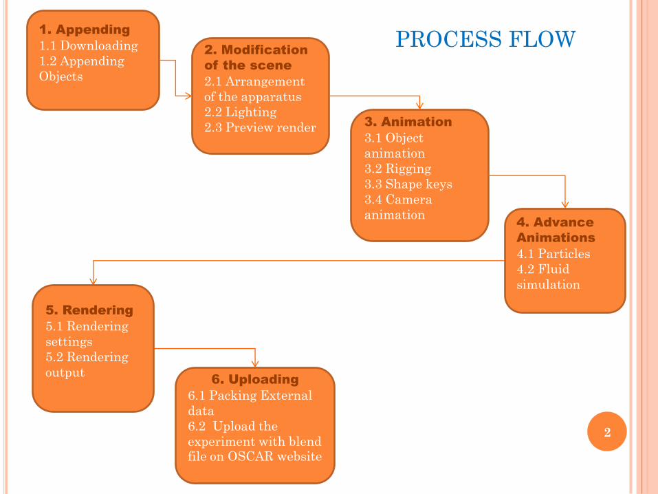
PROCESS FLOW1. Appending
1.1 Downloading
1.2 Appending
Objects
2. Modification
of the scene
2.1 Arrangement
of the apparatus
2.2 Lighting
2.3 Preview render 3. Animation
3.1 Object
animation
3.2 Rigging
3.3 Shape keys
3.4 Camera
animation4. Advance
Animations
4.1 Particles
4.2 Fluid
simulation
5. Rendering
5.1 Rendering
settings
5.2 Rendering
output6. Uploading
6.1 Packing External
data
6.2 Upload the
experiment with blend file on OSCAR website
2
1.1. Downloading
1. Make a new folder and rename it as your experiment’s
name
2. In this folder, download the default file for Lab setup
which has a base(table), light setup & Camera named
Lab_basic_setup_cycles.blend from the OSCAR
website (after the file gets uploaded there)
http://oscar.iitb.ac.in/blenderrepository.do
3. In the same folder, download blend files for the apparatus
required for your experiments from the link mentioned
above as per the category.
1. APPENDING
3
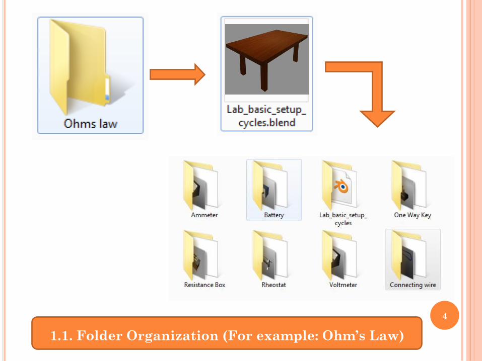
1.1. Folder Organization (For example: Ohm’s Law)
4
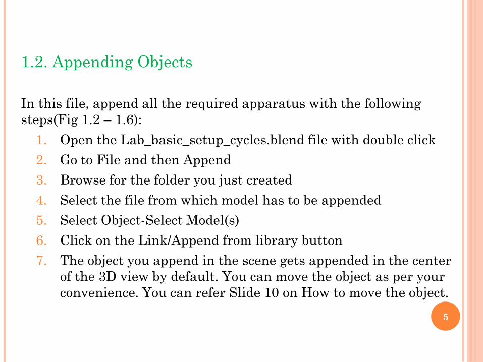
1.2. Appending Objects
In this file, append all the required apparatus with the following
steps(Fig 1.2 – 1.6):
1. Open the Lab_basic_setup_cycles.blend file with double click
2. Go to File and then Append
3. Browse for the folder you just created
4. Select the file from which model has to be appended
5. Select Object-Select Model(s)
6. Click on the Link/Append from library button
7. The object you append in the scene gets appended in the center
of the 3D view by default. You can move the object as per your
convenience. You can refer Slide 10 on How to move the object.
5
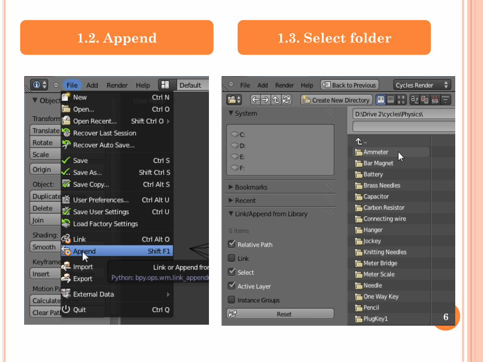
1.2. Append 1.3. Select folder
6
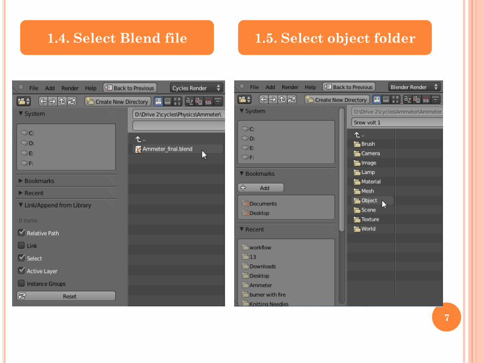
1.4. Select Blend file 1.5. Select object folder
7
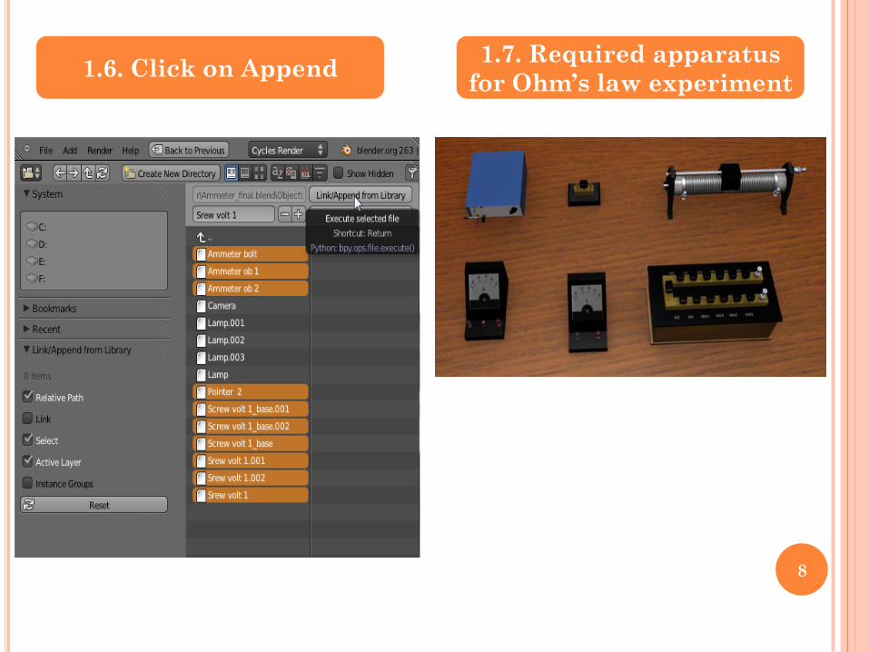
1.6. Click on Append 1.7. Required apparatus
for Ohm’s law experiment
8
2. MODIFICATION OF THE SCENE
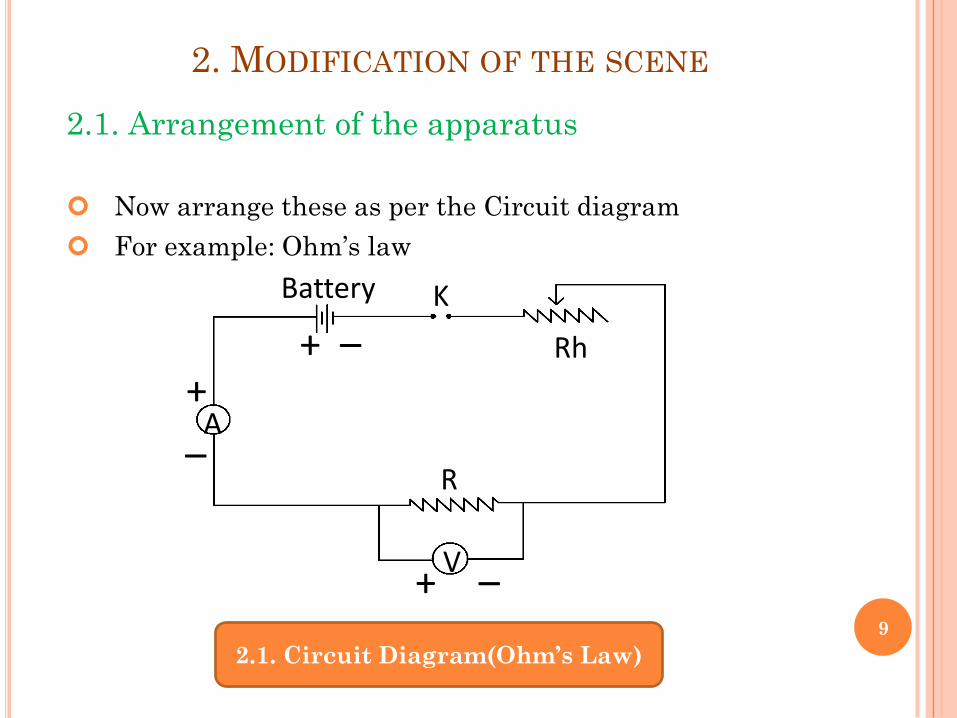
2.1. Arrangement of the apparatus
Now arrange these as per the Circuit diagram
For example: Ohm’s law
A+
–
–+
+ –V
Rh
R
KBattery
2.1. Circuit Diagram(Ohm’s Law)
9
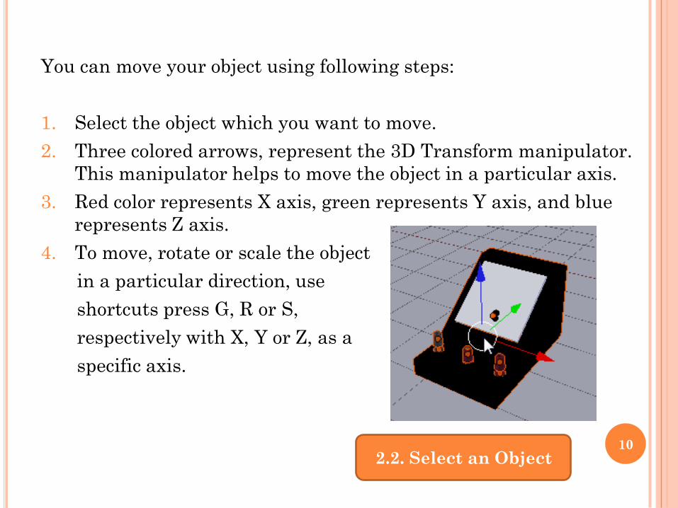
You can move your object using following steps:
1. Select the object which you want to move.
2. Three colored arrows, represent the 3D Transform manipulator.
This manipulator helps to move the object in a particular axis.
3. Red color represents X axis, green represents Y axis, and blue
represents Z axis.
4. To move, rotate or scale the object
in a particular direction, use
shortcuts press G, R or S,
respectively with X, Y or Z, as a
specific axis.
2.2. Select an Object10
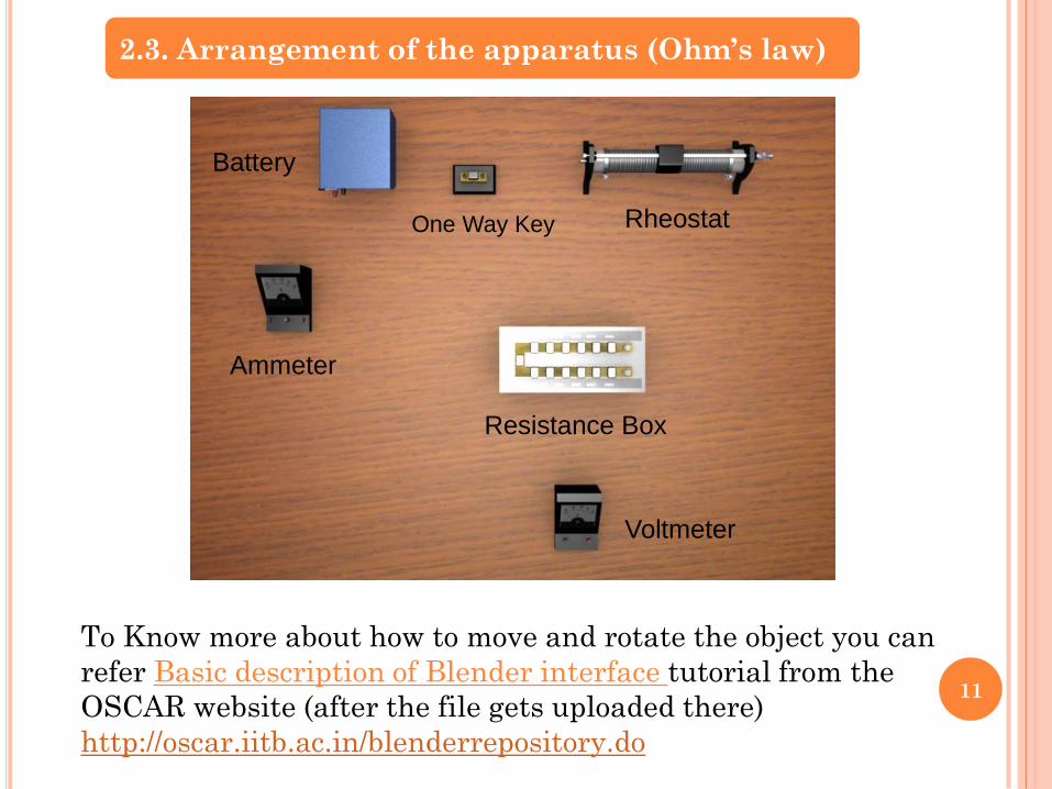
2.3. Arrangement of the apparatus (Ohm’s law)
To Know more about how to move and rotate the object you can
refer Basic description of Blender interface tutorial from the
OSCAR website (after the file gets uploaded there)
http://oscar.iitb.ac.in/blenderrepository.do
Ammeter
Battery
Resistance Box
One Way Key Rheostat
Voltmeter
11
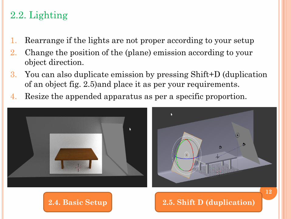
2.2. Lighting
1. Rearrange if the lights are not proper according to your setup
2. Change the position of the (plane) emission according to your
object direction.
3. You can also duplicate emission by pressing Shift+D (duplication
of an object fig. 2.5)and place it as per your requirements.
4. Resize the appended apparatus as per a specific proportion.
2.4. Basic Setup 2.5. Shift D (duplication)
12
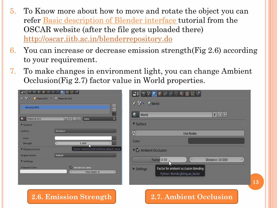
5. To Know more about how to move and rotate the object you can
refer Basic description of Blender interface tutorial from the
OSCAR website (after the file gets uploaded there)
http://oscar.iitb.ac.in/blenderrepository.do
6. You can increase or decrease emission strength(Fig 2.6) according
to your requirement.
7. To make changes in environment light, you can change Ambient
Occlusion(Fig 2.7) factor value in World properties.
2.6. Emission Strength 2.7. Ambient Occlusion
13
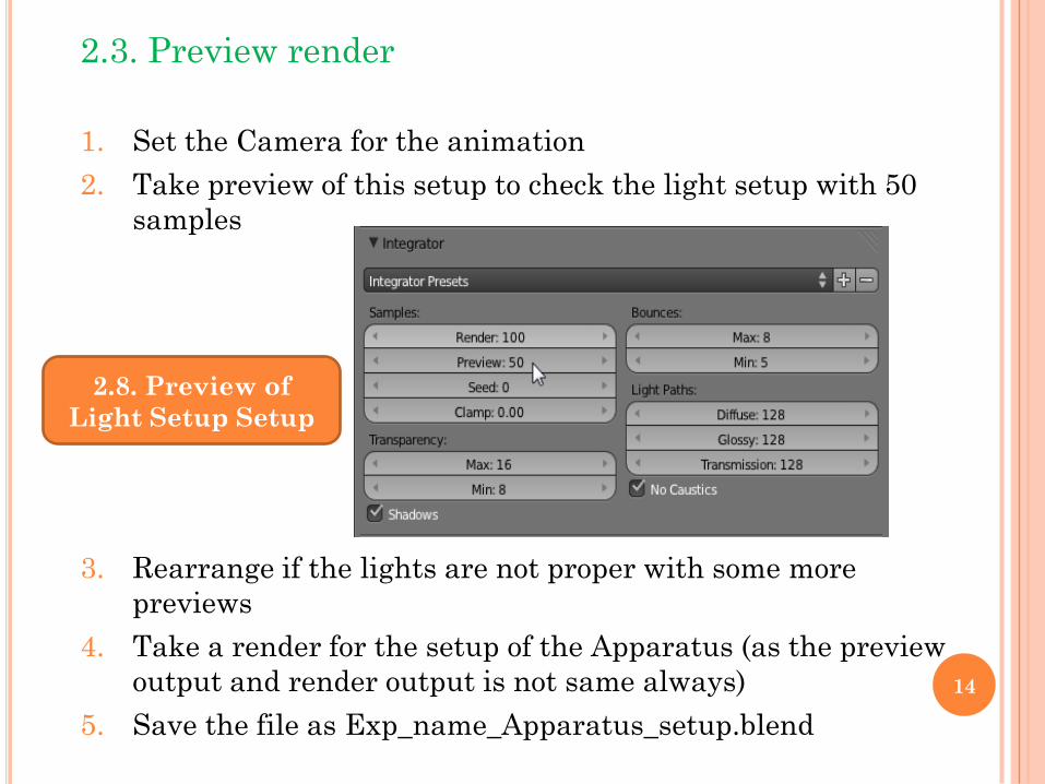
2.3. Preview render
1. Set the Camera for the animation
2. Take preview of this setup to check the light setup with 50
samples
3. Rearrange if the lights are not proper with some more
previews
4. Take a render for the setup of the Apparatus (as the preview
output and render output is not same always)
5. Save the file as Exp_name_Apparatus_setup.blend
2.8. Preview of
Light Setup Setup
14
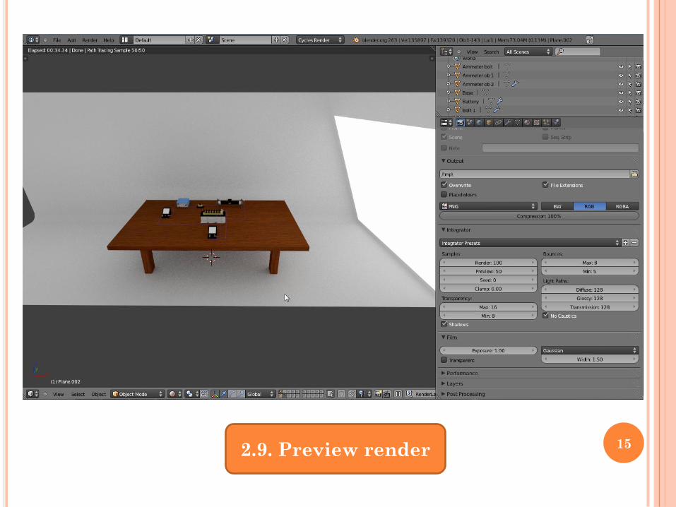
2.9. Preview render 15
3.1. Object animation
1. You can animate your object adding key frames on timeline.
2. Select your object which you want to animate.
3. Red color represents X axis, green represents Y axis, and blue
represents Z axis.
4. Press G to move, R to rotate and S to scale the object.
5. To move, rotate or scale the object in a particular direction by
using following shortcut press G, R or S and after that press X, Y
or Z.
6. To Know more about how to move and rotate the object you can
refer Basic description of Blender interface tutorial from the
OSCAR website (after the file gets uploaded there)
http://oscar.iitb.ac.in/blenderrepository.do and you can also refer
to http://en.wikibooks.org/wiki/Blender_3D:_Noob_to_Pro
3. ANIMATION
16
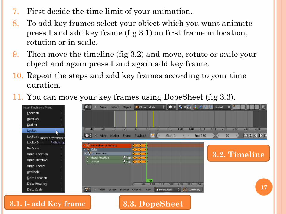
7. First decide the time limit of your animation.
8. To add key frames select your object which you want animate
press I and add key frame (fig 3.1) on first frame in location,
rotation or in scale.
9. Then move the timeline (fig 3.2) and move, rotate or scale your
object and again press I and again add key frame.
10. Repeat the steps and add key frames according to your time
duration.
11. You can move your key frames using DopeSheet (fig 3.3).
3.1. I- add Key frame
3.2. Timeline
3.3. DopeSheet
17
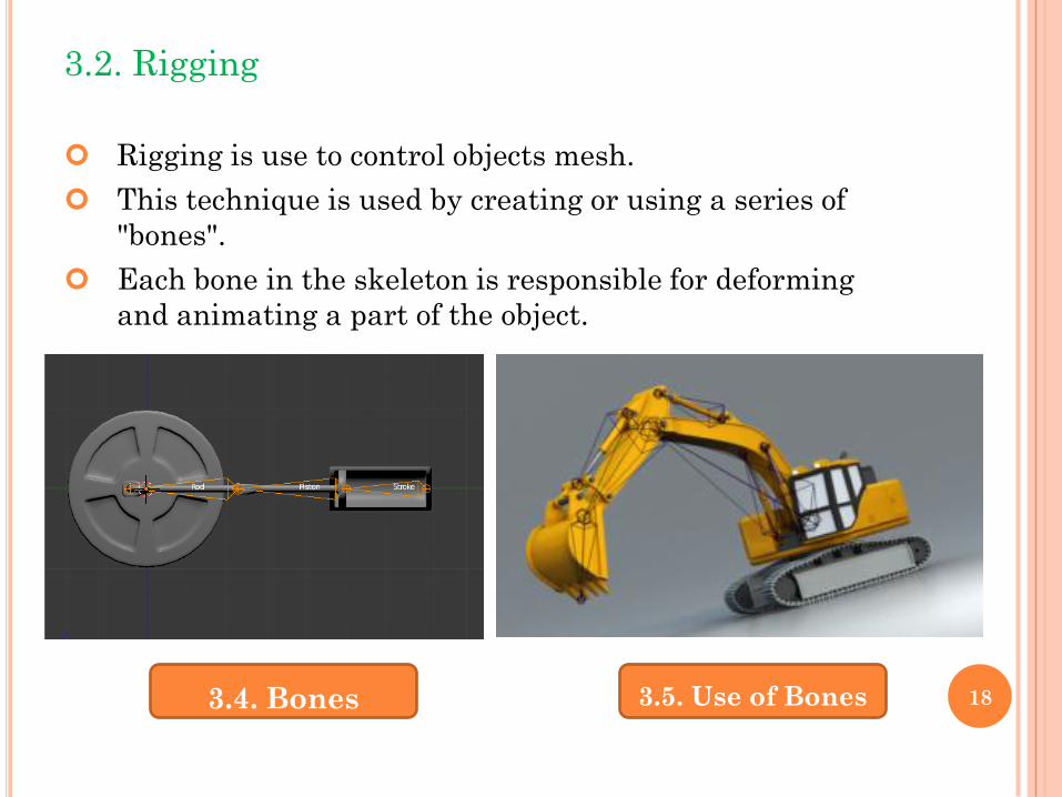
3.2. Rigging
Rigging is use to control objects mesh.
This technique is used by creating or using a series of
"bones".
Each bone in the skeleton is responsible for deforming
and animating a part of the object.
3.4. Bones 3.5. Use of Bones 18
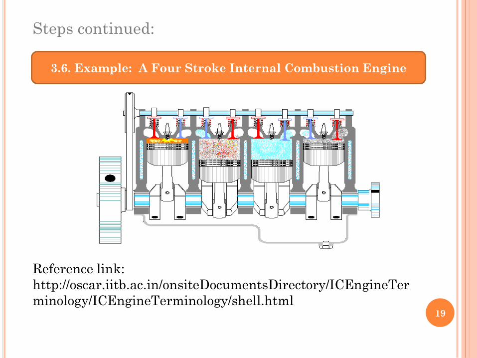
Steps continued:
Reference link:
http://oscar.iitb.ac.in/onsiteDocumentsDirectory/ICEngineTer
minology/ICEngineTerminology/shell.html
3.6. Example: A Four Stroke Internal Combustion Engine
19
Steps continued:
In this animation each part is connected with each other
so you can use rigging for this kind of animations.
For example: Ropes, chains, wire, other gear used to
support or for equipment you can use rigging.
Armature objects used for rigging.
The Armature Object Armatures are like articulated
skeletons, that allow you to pose and deform the
geometry that surrounds it. An armature is made of a
series of bones connected to each other via parenting or
constraints.
Editing Armatures Armatures are comprised of Bones.
Editing an Armature in Edit Mode allows you to
manipulate the bones in their default rest position. 20
Steps continued:
Posing Armatures Contrary to Edit Mode, Pose mode isn't
a obligatory mode where you can't do anything else. You
can be in Pose mode and still select another object. When
you are done building your armature, you can go into
Pose Mode to add constraints and start creating actions.
Animation After rigging is done you can move bones in
pose mode and add key frames on timeline.
To learn more about rigging please refer tutorials on
http://en.wikibooks.org/wiki/Blender_3D:_Noob_to_Pro/Ad
vanced_Tutorials/Advanced_Animation/Guided_tour/Arm
ature/index
21
3.3. Shape keys
Shape keys store different shapes of a same object (mesh,
curve, surface or lattice). In other 3D applications they
are called “morph targets”, “blend shapes”, or even
“vertex keys” in older versions of Blender. They are the
only way to directly animate the shape of your object.
Relative shape keys have (by default) one key (the first
one) as basis, and all others can be used to blend this
basis with their own shapes (optionally limiting their
effects to a given vertex group). Each of these “relative”
shapes’ influence can be animated with its own Ipo curve,
exactly as you would animate the influence of
constraints.
For more information on this, refer to
http://en.wikibooks.org/wiki/Blender_3D:_Noob_to_Pro/A
dvanced_Tutorials/Advanced_Animation/Guided_tour/Me
sh/Shape
22
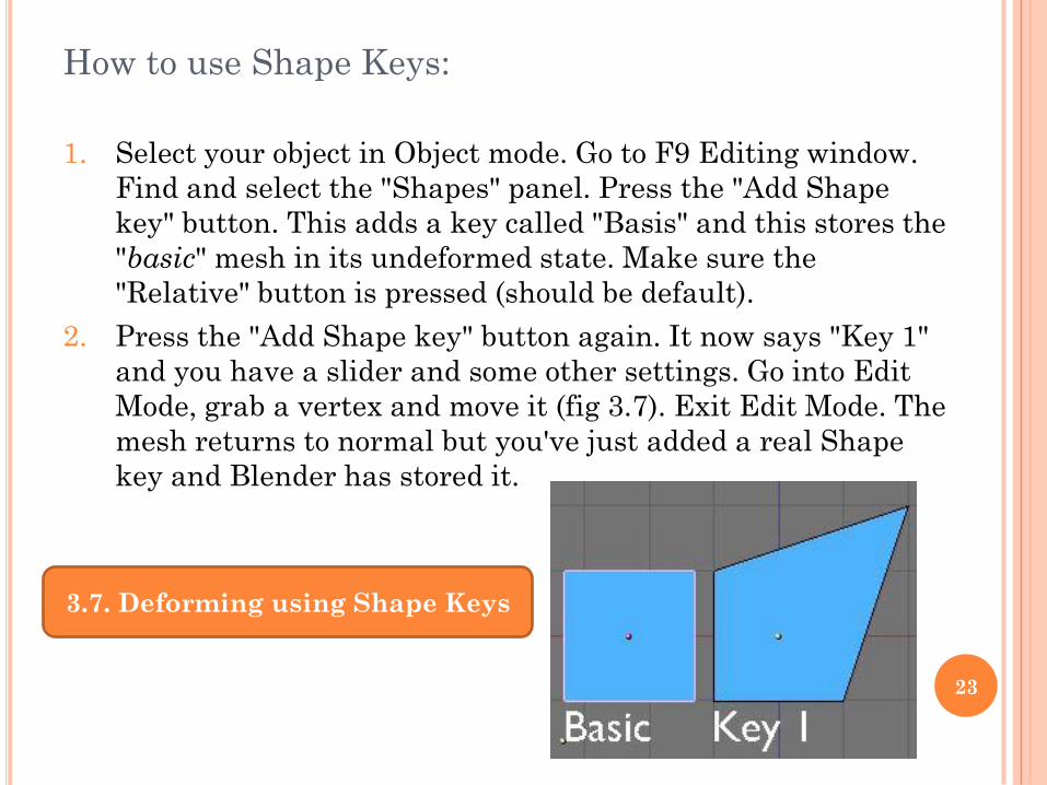
How to use Shape Keys:
1. Select your object in Object mode. Go to F9 Editing window.
Find and select the "Shapes" panel. Press the "Add Shape
key" button. This adds a key called "Basis" and this stores the
"basic" mesh in its undeformed state. Make sure the
"Relative" button is pressed (should be default).
2. Press the "Add Shape key" button again. It now says "Key 1"
and you have a slider and some other settings. Go into Edit
Mode, grab a vertex and move it (fig 3.7). Exit Edit Mode. The
mesh returns to normal but you've just added a real Shape
key and Blender has stored it.
3.7. Deforming using Shape Keys
23
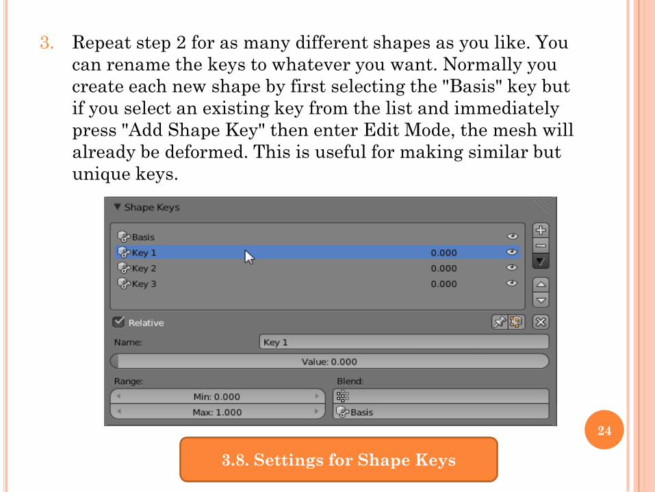
3. Repeat step 2 for as many different shapes as you like. You
can rename the keys to whatever you want. Normally you
create each new shape by first selecting the "Basis" key but
if you select an existing key from the list and immediately
press "Add Shape Key" then enter Edit Mode, the mesh will
already be deformed. This is useful for making similar but
unique keys.
3.8. Settings for Shape Keys
24
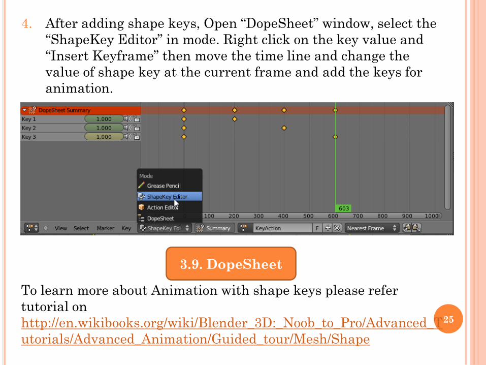
4. After adding shape keys, Open “DopeSheet” window, select the
“ShapeKey Editor” in mode. Right click on the key value and
“Insert Keyframe” then move the time line and change the
value of shape key at the current frame and add the keys for
animation.
To learn more about Animation with shape keys please refer
tutorial on
http://en.wikibooks.org/wiki/Blender_3D:_Noob_to_Pro/Advanced_T
utorials/Advanced_Animation/Guided_tour/Mesh/Shape
3.9. DopeSheet
25
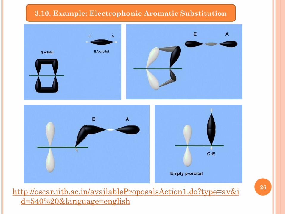
http://oscar.iitb.ac.in/availableProposalsAction1.do?type=av&i
d=540%20&language=english
3.10. Example: Electrophonic Aromatic Substitution
26
3.4. Camera Animation:
1. First decide the time limit of your experiment.
2. In basic setup camera is already attached with the locater. (Fig
3.11)
3. Locater is used for the object,
4. Because of the locater you can rotate the camera around the
object.
5. You can place the locater on the object which you want to focus.
6. In general, you can follow these steps:
a) Select empty press S or select the Translate manipulator from the
3D view
b) Using the 3D transform manipulator, move the cube in X Y and Z
directions
c) Move the empty and place it in the center of the object
27
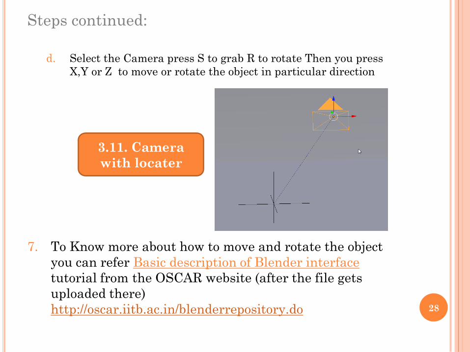
Steps continued:
d. Select the Camera press S to grab R to rotate Then you press
X,Y or Z to move or rotate the object in particular direction
7. To Know more about how to move and rotate the object
you can refer Basic description of Blender interface
tutorial from the OSCAR website (after the file gets
uploaded there)
http://oscar.iitb.ac.in/blenderrepository.do
3.11. Camera
with locater
28
Steps continued:
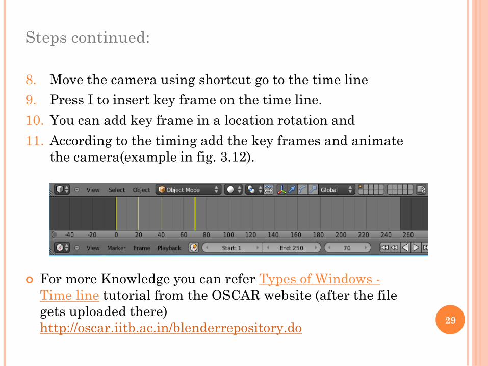
8. Move the camera using shortcut go to the time line
9. Press I to insert key frame on the time line.
10. You can add key frame in a location rotation and
11. According to the timing add the key frames and animate
the camera(example in fig. 3.12).
For more Knowledge you can refer Types of Windows -
Time line tutorial from the OSCAR website (after the file
gets uploaded there)
http://oscar.iitb.ac.in/blenderrepository.do29
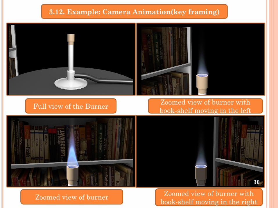
3.12. Example: Camera Animation(key framing)
Full view of the BurnerZoomed view of burner with
book-shelf moving in the left
Zoomed view of burnerZoomed view of burner with
book-shelf moving in the right
30
4. ADVANCE ANIMATION
4.1. Particles:
Particles are lots of items emitted from mesh objects,
typically in the thousands. Each particle can be a point of
light or a mesh, and be joined or dynamic. They may react to
many different influences and forces, and have the notion of
a lifespan.
Dynamic particles can represent fire, smoke, mist, and other
things such as dust or magic spells. Static particles form
strands and can represent hair, grass and bristles.
To learn more about rigging please refer tutorials on
http://en.wikibooks.org/wiki/Blender_3D:_Noob_to_Pro/Partic
le_Systems
31
In general, you can follow these steps:
1. Create the base mesh which will emit the particles. This
mesh is not rendered by default, but the base material for the
mesh is used to color the particles. Since a mesh can carry
multiple materials, each particle system may have its own
material.
2. Create one or more Particle Systems to emit from the mesh.
Many times, multiple particle systems interact or merge with
each other to achieve the overall desired effect.
3. Tailor each Particle System’s settings to achieve the desired
effect.
4. Animate the base mesh and other particle meshes involved in
the scene.
5. Define and shape the path and flow of the particles.
32
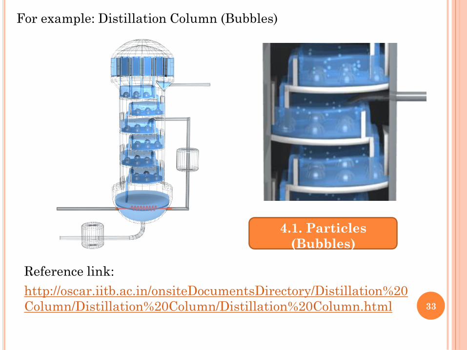
For example: Distillation Column (Bubbles)
Reference link:
http://oscar.iitb.ac.in/onsiteDocumentsDirectory/Distillation%20
Column/Distillation%20Column/Distillation%20Column.html
4.1. Particles
(Bubbles)
33
4.2. Fluid Simulation :
The bounding box of another object will be used to define a
box-shaped region to simulate the fluid in (the so called
“simulation domain”). The global simulation parameters
(such as viscosity and gravity) can be set for this domain
object.
Using the BAKE button, the geometry and settings are
exported to the simulator and the fluid simulation is
performed, generating a surface mesh together with a
preview for each animation frame, and saving them to hard
disk. Then the appropriate fluid surface for the current
frame is loaded from disk and displayed or rendered.
For more information refer to
http://en.wikibooks.org/wiki/Blender_3D:_Noob_to_Pro/Unde
rstanding_the_Fluid_Simulator
34
In general, you can follow these steps:
1. Set the simulation domain (the portion of the scene where the
fluid will flow),
2. Set the fluid source(s), and specify its material, viscosity, and
initial velocity,
3. Eventually, set other objects to control the volume of the fluid
(inlets and outlets),
4. Eventually, set other objects related to the fluid, like:
obstacles,
particles floating on the fluid,
fluid control, to shape part of the fluid in the desired form,
5. Eventually, animate the fluid properties,
6. Bake the simulation (eventually, revise as necessary and bake
repeatedly). 35
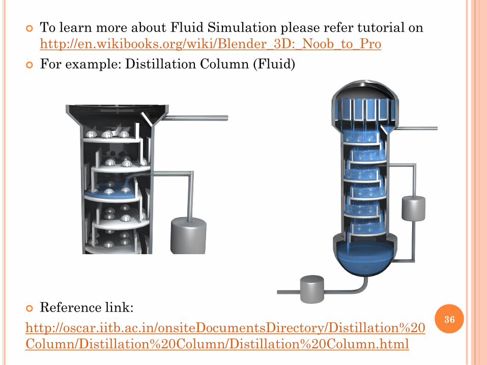
To learn more about Fluid Simulation please refer tutorial on
http://en.wikibooks.org/wiki/Blender_3D:_Noob_to_Pro
For example: Distillation Column (Fluid)
Reference link:
http://oscar.iitb.ac.in/onsiteDocumentsDirectory/Distillation%20
Column/Distillation%20Column/Distillation%20Column.html
36
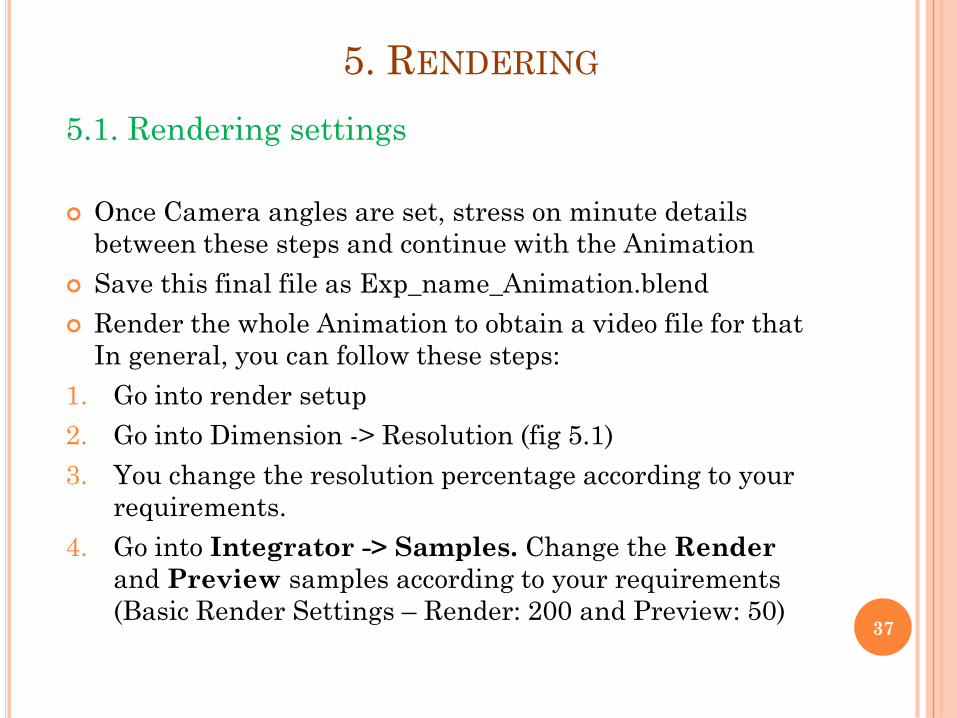
5.1. Rendering settings
Once Camera angles are set, stress on minute details
between these steps and continue with the Animation
Save this final file as Exp_name_Animation.blend
Render the whole Animation to obtain a video file for that
In general, you can follow these steps:
1. Go into render setup
2. Go into Dimension -> Resolution (fig 5.1)
3. You change the resolution percentage according to your
requirements.
4. Go into Integrator -> Samples. Change the Render
and Preview samples according to your requirements
(Basic Render Settings – Render: 200 and Preview: 50)
5. RENDERING
37
Steps Continued:
5. You can Increase the value of Transparency, Bounce
and Light Paths for better output.
6. Image is used to render a single frame of the active
camera view.
7. Press F12. The active camera view is rendered as a single
frame image.
8. Left click Create new directory. Type OUTPUT and press
enter.
9. Left click Output to open the folder.
10. Left click Accept. Now all our Render files will be saved in
the Output Folder in My Documents.
11. Below the Output Folder bar is the Image format menu.
Here we can choose our Output format for our Render
images and movie files.
12. Below PNG are the three color modes used in Blender.
You can chose according to your requirements.
38
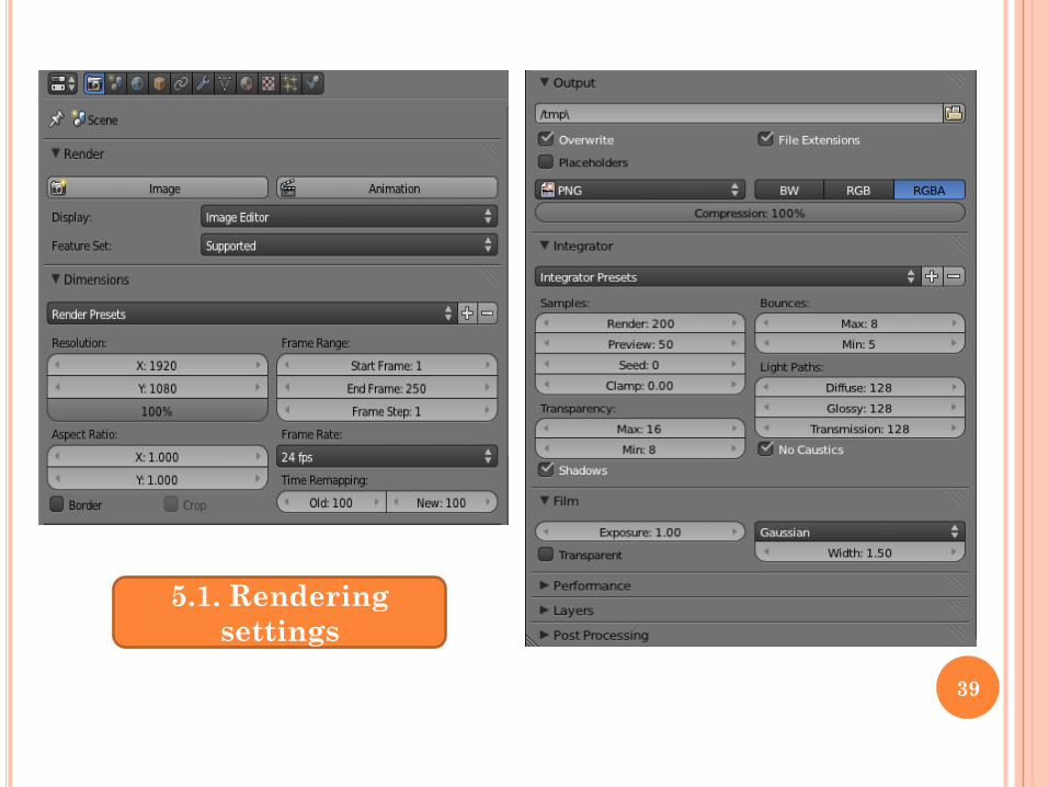
5.1. Rendering
settings
39
5.2. Rendering output
1. Animation is used to render an entire range of frames or
an image sequence and create a movie file. Esc to stop the
render progress.
2. Left click Animation. The entire frame range will getting
rendered.
3. For more Information you can refer Properties part-1
tutorial from the OSCAR website (after the file gets
uploaded there) http://oscar.iitb.ac.in/blenderrepository.do
and you can also refer to
http://en.wikibooks.org/wiki/Blender_3D:_Noob_to_Pro/Re
nder_Settings
40
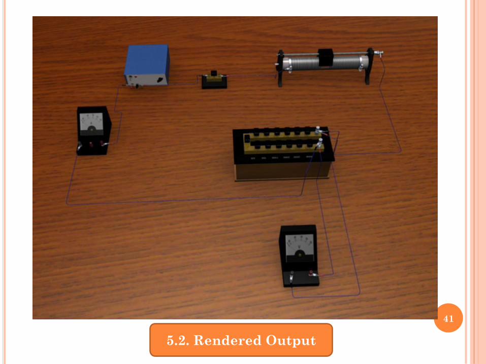
5.2. Rendered Output
41
6.1 Packing External data
Each .blend file contains a database. This database
contains all scenes, objects, meshes, textures, etc. that are
in the file. A file can contain multiple scenes and each
scene can contain multiple objects. Objects can contain
multiple materials which can contain many textures. It is
also possible to create links between different objects.
Pack into .blend file:
1. Blender has the ability to encapsulate (incorporate)
various kinds of data within the .blend file that is
normally saved outside of the .blend file.
2. For example, an image texture that is an external .jpg file
can be put “inside” the .blend file via File → External
Data → Pack into .blend file. (fig 6.1)
6. UPLOADING
42
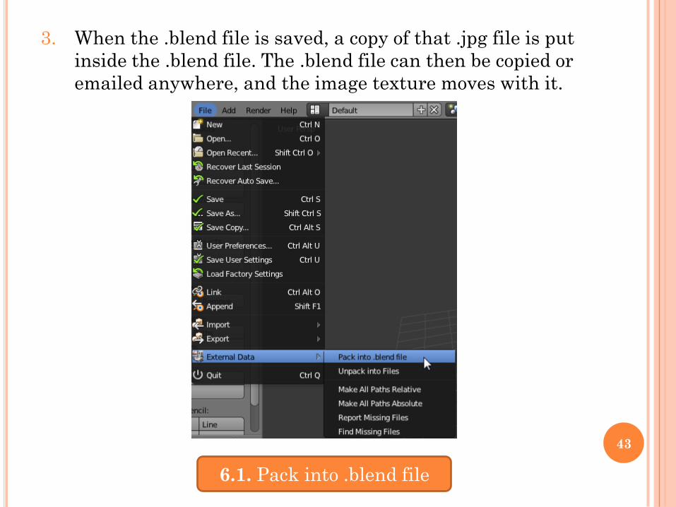
3. When the .blend file is saved, a copy of that .jpg file is put
inside the .blend file. The .blend file can then be copied or
emailed anywhere, and the image texture moves with it.
6.1. Pack into .blend file
43
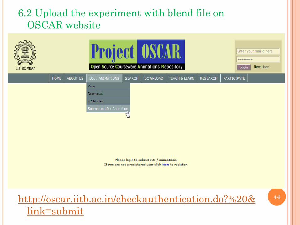
6.2 Upload the experiment with blend file on
OSCAR website
http://oscar.iitb.ac.in/checkauthentication.do?%20&
link=submit
44

45