Embed Size (px)
Citation preview
Structural Analysis of Historical Constructions - Modena, Lourenço & Roca (eds) © 2005 Taylor & Francis Group, London, ISBN 04 1536 379 9
Methodology for the analysis of complex historical wooden structures: a study case
F.M. Mazzolani, B. Faggiano & A. Marzo Dept. 01 Structural Analysis and Design, University 01 Naples "Federico 11 ", Nap/es, Ita/y
A8STRACT: The paper deals with the analysis ofthe behaviour of a complex structure made of ancient wood. To this purpose, ali the problems related with the structural modelling and analysis have been faced. In particular, with reference to a study case, which is the roofing structures of the Diplomatic Hall of the Royal Palace of Naples, the detailed geometrical and mechanical surveys have been presenteei, as pre!iminary and indispensable phases for the structural identification, to be carried out by means of both in situ investigations and laboratory tests on ancient wood specimens. On the basis ofthe results ofthe structural analysis , by means of a 3D model , the safety checks, according to the EC5 provisions, have identified the capacity of the structure in terms of resistance and deformation.
INTRODUCTlON
Preservation and restoration of historical wooden structures are a very actual matter in ali the European countries, owing to the large use ofthis constructional type during the past.
The analysis of ancient structures made of wood is undoubtedly very cumbersome for several inherent difficulties to be faced for both the material and the structural behaviour characterization. Generally, structures in ancient wood are subject to various imperfections. On one hand they are related to the material nature, for example damage for material shrinkage and ring shake due to aging and deterioration, and to degradation due to insect and mushroom attacks. On the other hand they depend on the remarkable irregularities due to the past technologies.
The study of the existing wooden structural elements, firstly requires preliminary knowledge of the characteristics and the classification cri teria of the corresponding new wood anel, secondly, the evaluation of the deterioration degree by means of specific procedures and methods. To this purpose, it is of fundamental importance to perform an in-depth survey of the structure and the relevant degradation of the properties of construction materiaIs, of the environrnental conditions and finally of the serviceability conditions, which the structure has undergone during its !ife. Once ali the necessary knowledge has been achieved through these investigations, it is possible to evaluate the bearing capacity of the
single structural element and its contribution to the behaviour of the whole structure. Next step consequently consists in designing appropriate restoration intervention.
In this context, the pape r faces the analysis of the behaviour of a complex structure made of ancient wood. The attention has been focused on a study case (Marzo, 2003), which is the roofing structures of the Diplomatic Hall of the Royal Palace of Naples (ltaly). The detailed geometric and mechanical surveys have been presenteei, as preliminary and indispensable phases for a consistent analysis of stress and strain states in the structure (Uzielli , 200 I). On the basis of the acquired knowledge, a 3D model of the structure has been set up, by using a FEM programme.
The analysis of the structural behaviour has evidenced the weaknesses of the structure in terms of resistance and deformation capabilities. The safety checks have been performed according to the European provisions, Eurocode 5 (CEN, prEN 1995-1-1 , 2002) "Design of timber structures" and to the final document ofthe proposal for the Italian technical provisions for design oftimber structures (200 I). In fact, at present, the Ita!ian structural codes do not officially include structures made of wood. 80th the European codes and the proposal for the new Italian codification refer to new wood constructions. The use of such provisions to the ancient wood requires appropriate consideration based on the results of experimental investigations.
945
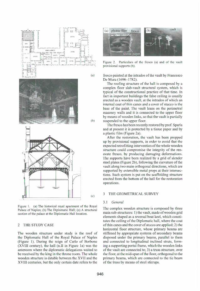
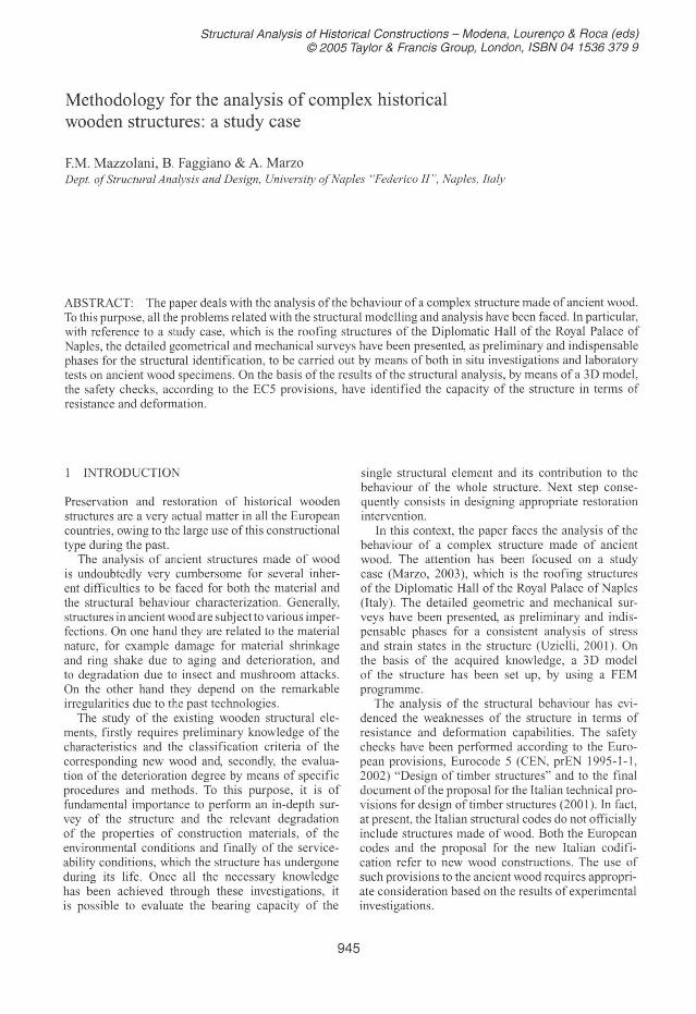
Figure I. (a) The historical royal apartment of the Royal Palace of Naples; (b) The Diplomatic Hall ; (c) A structura l section ofthe palace at the Diplomatic Hal l location.
2 THE STUDY CASE
The wooden structure under study is the roof of the Diplomatic Hall of the Royal Palace of Naples (Figure I). During the reign of Carlo of Borbone (XVIII century), the hall (n.lI in Figure la) was the anteroom where the diplomatic delegations waited to be received by the king in the throne room. The whole wooden structure is datable between the XVII and the XVIII centuries, but the only certain date refers to the
Figure 2. Particulars of the fresco (a) and of the vault provisional supports (b).
fresco painted at the intrados oflhe vau lt by Francesco De Mura (1696- 1782).
The roofing slructure of lhe haJl is composed by a complex tloor slab-vault structural system, which is typical of the conslructional practice of lhat time. In fact in important buildings lhe false ceiling is usually erected as a wooden vault, at the intrados of which an internai coat of thin canes and a cover of stucco is the base of the paint. The vault leans on the perimetral masonry walls and it is connected to the upper tloor by means ofwooden links, so that the vault is partially suspended to the upper tloor.
The fresco has been recently restored by prof. Sparla and at present it is protected by a tissue paper and by a plaslic film (Figure 2a).
Afier the restoration, lhe vault has been propped up by provisional supports, in order to avoid that the expected retrofitting intervention ofthe whole wooden structure could compromise the integrity of the renovate fresco, by producing damaging deformations. The supports have been realized by a grid of slender steel plates (Figure 2b), following the curvature ofthe vault along two main orthogonal directions, which are supported by extensible metal props at their intersections. Such system is put on the scaffolding structure erected from the bottom of the ball for the restoration operations.
3 THE GEOMETRICAL SURVEY
3.1 General
The complex wooden structure is composed by three main sub-structures: I) the vault, ma de ofwooden grid elements shaped as a reversal boat keel, which constitutes the ceiling ofthe Diplomatic haJl , where the coat ofthin canes and the cover ofstucco are applied; 2) the horizontal floor structure, whose primary beams are stiffened by appropriate systems of secondary beams disposed under the primary beams, parallel to them and connected to longitudinal inclined struts, forming a supporting portal frame, which the wooden links of the vault are connected to; 3) a truss structure, over the tloor, at the mid-span ofthe tloor, orthogonal to the primary beams, which are connected to the tie beam of the truss by means of steel stirrups.
946
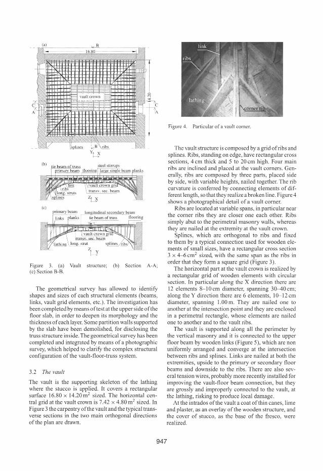
Figure 3. (a) Vault structure; (b) Section A-A; (c) Section B-B.
The geometrical survey has allowed to identify shapes and sizes of each structural elements (beams, links, vault grid elements, etc.). The investigation has been completed by means oftest at the upper side ofthe floor slab, in order to deepen its morphology and the thickness of each layer. Some partition walls supported by the slab have been demolished, for disclosing the truss structure inside. The geometrical survey has been completed and integrated by means of a photographic survey, which helped to clarify the complex structural configuration of the vault-floor-truss system.
3.2 The vau/t
The vault is the supporting skeleton of the lathing where the stucco is applied. It covers a rectangular surface 16.80 x 14.20 m2 sized. The horizontal central grid at the vault crown is 7.42 x 4.80 m2 sized. In Figure 3 the carpentry ofthe vault and the typical transverse sections in the two main orthogonal directions ofthe plan are drawn.
Figure 4. Particular of a vault comer.
The vault structure is composed by a grid ofribs and splines. Ribs, standing on edge, have rectangular cross sections, 4 em thick and 5 to 20 cm high. Four main ribs are inclined and placed at the vault comers. Generally, ribs are composed by three parts, placed side by side, with variable heights, nailed together. The rib curvature is conferred by connecting elements of different length, so that they realize a broken line. Figure 4 shows a photographical detail of a vault comer.
Ribs are located at variable spans, in particular near the corner ribs they are closer one each other. Ribs simply abut to the perimetral masonry walls, whereas they are nailed at the extremity at the vault croWll.
Splines, which are orthogonal to ribs and fixed to them by a typical connection used for wooden elements of small sizes, have a rectangular cross section 3 x 4-6 cm2 sized, with the same span as the ribs in order that they form a square grid (Figure 3).
The horizontal part at the vault crown is realized by a rectangular grid of wooden elements with circular section. In particular along the X direction there are 12 elements 8- 10 cm diameter, spanning 30-40 cm; along the Y direction there are 6 elements, 10-12 cm diameter, spanning 1.00 m. They are nailed one to another at the intersection point and they are enclosed in a perimetral rectangle, whose elements are nailed one to another and to the vault ribs.
The vault is supported along ali the perimeter by the vertical masonry and it is connected to the upper floor beam by wooden links (Figure 5), which are non uniformly arranged and converge at the intersection between ribs and splines. Links are nailed at both the extremities, upside to the primary or secondary floor beams and downside to the ribs. There are also several tension wires, probably more recently installed for improving the vault-floor beam connection, but they are grossly and improperly connected to the vault, at the lathing, risking to produce local damage.
At the intrados ofthe vault a coat ofthin canes, lime and plaster, as an overlay ofthe wooden structure, and the cover of stucco, as the base of the fresco, were realized.
947
3.3 The beamfloor
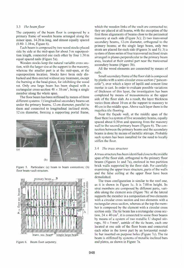
The carpentry of the beam floor is composed by a pnmary frame of wooden beams arranged along the mmor span, 14.20 m long, and almost equally spaced (0.80- 1.10m, Figure 6). . Each beam is composed by two wood stocks placed
SI de by slde at the mid-span for about 5 m superposition length, connected one each other by four 1.50 m equal spaced nails (Figure 5a).
Wooden stocks keep the natural variable cross se ction, with the larger size at the support to the masonry, whereas the smaller part is at the mid-span, at the superposition location. Stocks have been only disbarked and then erected without any treatment, except the burnmg at the head-piece, for inhibiting the wood rot. Only one large beam has been shaped with a rectangular cross-section 48 x 38 cm2 , being a single member along the whole span.
The floor beam has been stiffened by means ofthree different systems: I) longitudinal secondary beams set under the primary beams, 12 cm diameter, parallel to them and connected to longitudinal inclined struts, 12 cm diameter, forming a supporting portal frame,
Figure 5. Particulars: (a) beam to beam connection; (b) fioor beam-vault structure.
Figure 6. Beam fioor carpentry.
which the wooden links ofthe vault are connected to' they are placed at ali beams, with the exception ofth~ first three alignments ofbeams close to the perimetral masonry at each side (Figure 3c); 2) two transversal secondary beams, 12 cm diameter, orthogonal to the primary beams; at the single large beam, only two struts are placed for each side (Figures 3c and 5); 3) a system ofthree series offour transversal inclined struts arranged in planes perpendicular to the primary beam axes, located at their central part near the transversal secondary beams (Figure 3b).
Ali the wood elements are connected by means of nai ls.
Small secondary frame ofthe floor slab is composed by planks with a semi-circular cross section ("panconcelle"), over which a layer of lapilli and cement li me morta r is cast. In order to evaluate possible variations of thickness of this layer, the investigation has been c?mpleted by means of measurements at the upper slde of the floor slab. As a result, the layer thickness varies from about 10 cm at the support to masonry to 40 cm m the mlddle span. Above such layer there is the majolica tile flooring.
Near the façade wall, at the middle span of the floor there's a system offive secondary beams, equally spaced about 0.50 m and spanning from the masonry wall to the second primary beam (Figure 6). The connection between the primary beams and the secondary beams IS done by means of metallic stirrups. Probably such system has been installed for the need to locally stiffen the floor.
3.4 The truss structure
A truss structure has been identified close to the middle span of the floor slab, orthogonal to the primary floor beams (Figures lc and 7a), enclosed in two partition brick walls supported by the floor slab. For carefully examining the upper truss structure, parts of the walls and the false ceiling at the upper floor have been demolished.
The truss configuration is similar to the roof one as it is shown in Figure lc. It is 7.00 m height. lt~ strut members are composed by different parts, variable along the element axis (Figure 7b): at the lateral supports the member is a composition oftwo elements with a circular cross section and two elements with a rectangular cross section, whereas at the top the member IS composed by the element with a circular cross section only. The tie beam has a rectangular cross section, 24 x 40 cm2 , it is connected to some floor beams by means of a system of two metallic U shaped stirrups, 50 x 5 mm2
, astride of the tie beam, each one located at one side of the floor beam and connected each other in the lower part by an horizontal metallic bar inserted on purpose holes (Figure 7c). The tie beam is stiffened by systems ofmetallic inclined bars and plates, as shown in Figure 7a.
948
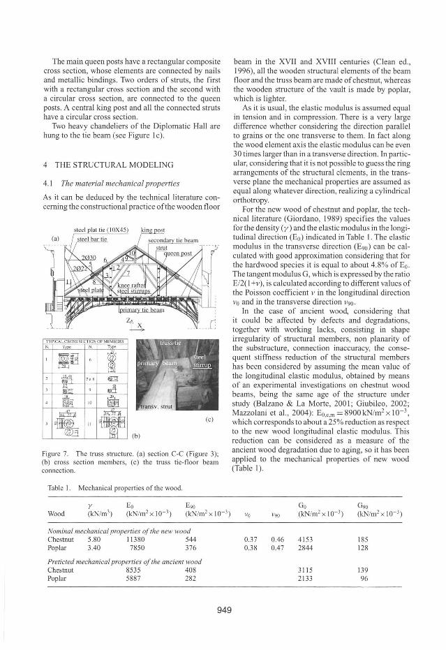
The main queen posts have a rectangular composite cross section, whose elements are connected by nails and metallic bindings. Two orders of struts, the first with a rectangular cross section and the second with a circular cross section, are connected to the queen posts. A central king post and ali the connected struts have a circular cross section.
Two heavy chandeliers of the Diplomatic Hall are hung to the tie beam (see Figure I c).
4 THE STRUCTURAL MODELING
4.1 The material mechanical properties
As it can be deduced by the technical literature concerning the constructional practice ofthe wooden floor
sleel piaI lie (I OX45)
TYPICAL CROSS SECfION DF MEMBERS N. T N. T}
~ lIiJ
,<8
10
11
Figure 7. The truss structure. (a) section C-C (Figure 3); (b) cross section members, (c) the truss tie-floor beam connection.
Table I. Mechanical properties of the wood.
Wood
Nominal mechanical properties o/lhe new wood Chestnut 5.80 11380 544 Poplar 3.40 7850 376
Preticled mechanical properties o/ lhe ancient wood Chestnut 8535 408 Poplar 5887 282
949
beam in the XVII and XVIII centuries (Clean ed ., 1996), ali the wooden structural elements of the beam floor and the truss beam are ma de of chestnut, whereas the wooden structure of the vault is made by poplar, which is lighter.
As it is usual, the elastic modulus is assumed equal in tension and in compression. There is a very large difference whether considering the direction parallel to grains or the one transverse to them. In fact along the wood element axis the elastic modulus can be even 30 times larger than in a transverse direction. In particular, considering that it is not possible to guess the ring arrangements of the structural elements, in the transverse plane the mechanical properties are assumed as equal along whatever direction, realizing a cylindrical orthotropy.
For the new wood of chestnut and poplar, the technical literature (Giordano, 1989) specifies the values for the density (y) and the elastic modulus in the longitudinal direction (Eo) indicated in Table I. The elastic modulus in the transverse direction (E90) can be calculated with good approximation considering that for the hardwood species it is equal to about 4.8% of Eo . The tangent modulus G, which is expressed by the ratio EI2( I +v), is calculated accord ing to different values of the Poisson coefficient v in the longitudinal direction Vo and in the transverse direction V90.
In the case of ancient wood, considering that it could be affected by defects and degradations, together with working lacks, consisting in shape irregularity of structural members, non planarity of the substructure, connection inaccuracy, the consequent stiffness reduction of the structural members has been considered by assuming the mean value of the longitudinal elastic modulus, obtained by means of an experimental investigations on chestnut wood beams, being the same age of the structure under study (Balzano & La Morte, 200 I; Giubileo, 2002; Mazzolani et aI. , 2004): Eo.e.m = 8900 kN/m2 x 10- 3,
which corresponds to about a 25% reduction as respect to the new wood longitudinal elastic modulus. This reduction can be considered as a measure of the ancient wood degradation due to aging, so it has been applied to the mechanical properties of new wood (Table I).
0.37 0.38
0.46 0.47
4153 2844
3115 2133
185 128
139 96
~----------4-54---~r-
(a) (b)
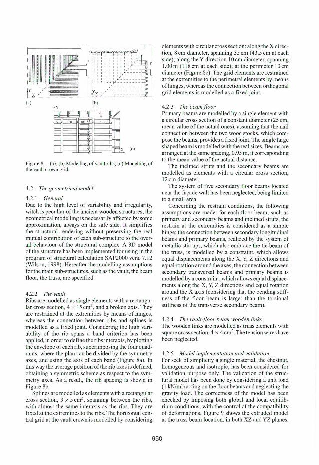
Figure 8. (a), (b) Modelling ofvault ribs; (c) Modelling of the vault crown grid.
4.2 The geometrical model
4 .2.1 General Due to the high leveI of variability and irregularity, witch is peculiar ofthe ancient wooden structures, the geometrical modeIling is necessarily atfected by some approximation, always on the safe side. It simplifies the structural rendering without preserving the real mutual contribution of each sub-structure to the overalI behaviour of the structural complex. A 3D model ofthe structure has been implemented for using in the program of structural calculation SAP2000 verso 7. 12 (Wilson, 1998). Hereafter the modeIling assumptions for the main sub-structures, such as the vault, the beam floor, the truss, are specified.
4.2.2 The vault Ribs are modelIed as single elements with a rectangular cross section, 4 x 15 cm2, and a broken axis. They are restrained at the extremities by means of hinges, whereas the connection between ribs and splines is modeIled as a fixed joint. Considering the high variability of the rib spans a band criterion has been applied, in order to define the ribs interaxis, by plotting the envelope of each rib, superimposing the four quadrants, where the plan can be divided by the symmetry axes, and using the axis of each band (Figure 8a). In this way the average position ofthe rib axes is defined, obtaining a symmetric scheme as respeet to the symmetry axes. As a result, the rib spacing is shown in Figure 8b.
Splines are modeIled as elements with a rectangular cross section, 3 x 5 cm2, spanning between the ribs, with almost the same interaxis as the ribs. They are fixed at the extremities to the ribs. The horizontal centrai grid at the vault crown is modeIled by considering
elements with circular cross section: along the X direction, 8 cm diameter, spanning 35 cm (43.5 cm at each side); along the Y direction 10 cm diameter, spanning 1.00 m (118 cm at each side); at the perimeter lO cm diameter (Figure 8e). The grid elements are restrained at the extremities to the perimetral elements by means ofhinges, whereas the connection between orthogonal grid elements is modeIled as a fixed joint.
4.2.3 The beamfloor Primary beams are modelled by a single element with a circular eross section of a constant diameter (25 cm, mean value ofthe aetual ones), assuming that the nail connection between the two wood stocks, which compose the beams, provides a fixedjoint. The single large shaped beam is modelled with the real sizes. Beams are arranged at the same spacing, 0.95 m, it corresponding to the mean value ofthe actual distance.
The inclined struts and the secondary beams are modeIled as elements with a circular cross section, 12 cm diameter.
The system of five secondary floor beams located near the façade waIl has been negleeted, being limited to a smaIl area.
Concerning the restrain conditions, the foIlowing assumptions are made: for each floor beam, sueh as primary and secondary beams and inclined struts, the restrain at the extremities is considered as a simple hinge; the connection between secondary longitudinal beams and primary beams, realized by the system of metallic stirrups, which also embrace the tie beam of the truss, is modeIled by a constraint, which aIlows equal displacements along the X, Y, Z directions and equal rotation around the axes; the connection between secondary transversal beams and primary beams is modelled by a constraint, which allows equal displacements along the X, Y, Z directions and equal rotation around the X axis (considering that the bending stitfness of the floor beam is larger than the torsional stitfness of the transverse secondary beam).
4.2.4 The vault-floor beam wooden links The wooden links are modeIled as truss elements with square eross section, 4 x 4 cm2. The tension wires have been neglected.
4.2.5 Model implementation and validation For seek of simplicity a single material, the chestnut, homogeneous and isotropic, has been considered for validation purpose only. The validation of the structural model has been done by considering a unit load (I kN/ml) acting on the floor beams and neglecting the gravity load. The correctness of the model has been checked by imposing both global and local equilibrium conditions, with the eontrol ofthe compatibility of deformations. Figure 9 shows the extruded model at the truss beam location, in both XZ and YZ planes.
950
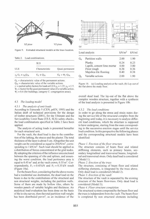
Figure 9. Extruded structural models at the truss location.
Table 2. Load combinations.
SLS
ULS Characteristic Quasi permanent
Yg Gk + YqQ lk Gk +Qlk Gk + 1/12 Qlk
Gk = characteristic value of lhe permanent actions. Qlk = characteristic value of the variable actions. Y = partial safety factors for loads at ULS Yg = 1.35, Yq = 1.5. 1/12 = facto r forthe quasi permanent value ora variable action. 1/12 = 0.6 (for buildings, category C: congregation areas).
4.3 Th e /oading mode/
4.3. 1 Th e ana/ysis of unit /oads According to Eurocode 5 (CEN, prEN, 1995) and the Italian draft of technical provisions for the design of timber structures (200 I) , for the Ultimate and the Serviceability Limit State (ULS, SLS) safety checks, the load combinations specified in Table 2 have been applied.
The analysis of acting loads is presented hereafter for each structural unit.
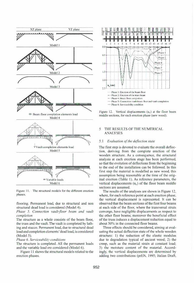
For the vault, the dead load is due to the contribution ofthe lathing, the stucco and the plaster. The total thickness ofthe layer is about 5 em. Altogether the unit weight can be considered as equal to 20 kN/m3 , corresponding to I kN/m2 Such load should be applied as a distribution offorces concentrated at the grid nodes. By adopting the criterion ofthe influence area enclosed between the spanning of ribs and splines, and assuming the worst condition, the load pertinence area is equal to 0.45 m2 anel, at the vault crown, 0.35 m2. Correspondently, F I = 0.45 kN and F2 = 0.35 kN result (Figure 10a).
For the beam floor, considering that the above rooms had a residential use destination, the dead load on the beam is due to the contributions of the structural and non structural weights, including the partition walls. Some of them are made by hollow tiles, others by wooden panels of variable heights and thickness. An analytical load evaluation has been done on the basis ofthe in situ survey, then the total partition wall weight has been distributed per m2
, as an incidence of the
951
Load analysis kN/m2 kN/ml
Gk Partition walls 2.00 1.90
Planks 0.24 0.23 Lapilli, cement lime mortar 4.00 3.80 Floor rough 0.38 0.36 Majolica tile flooring 0.40 0.38
Qk Variable actions 2.00 1.90
Figure 10. (a) Loading analysis at the vault , (b) Lay-out of the flat above lhe study floor.
overall dead load. The lay-out of the flat above the complex wooden structure, together with a synthesis of the load analysis is presented in Figure 10b.
4.3.2 The /oad conditions In order to go along the stress and strain states during the service life ofthe structural complex from the beginning until today, it is necessary to analyze different load conditions, which the structure is supposed to have undergone, starting from the ones corresponding to the successive erection stages until the service load condition. In this perspective the following phases and the corresponding structural models have been identified:
Phase I. Erection ofthefloorstructure The structure consists of beam floor and related stiffening elements, such as primary beams, secondary longitudinal and transversal beams, long itudinal and transversal struts. Only dead load is considered (Model I). Phase 2. Ereclion of lhe truss The structure, consisting of beam floor and related stiffening elements, is integrated by the truss above. Only dead load is considered (Mo dei 2). Phase 3. Erection of the vault The structure of the vault is separated by the existing structure of the beam floor-truss. Only dead load is considered (Model 3). Phase 4. F/oor Slructure comp/etion The structural system composed by the beam floor and the truss is independent f TOm the vault. The beam floor is completed by non structural elements including
XZ plane YZ plane
~ •......•... ~ ~
rn Beam fioor completion elements load Model4
~Vau lt completion elements load Model5
um Variable loads Model6
Figure J 1. The structural models for lhe di fferent erection phases.
flooring. Permanent load, due to structural and non structural dead load is considered (Model 4). Phase 5. Connection vault-floor beam and vault completion The structure as a whole consists of the beam floor, the truss and the vault. The vault is completed by lathing and stucco. Permanent load, due to structural dead load and completion elements' dead load, is considered (ModeI5). Phase 6. Serviceability conditions The structure is completed. All the permanent loads and the variable load are considered (Model 6).
Figure II shows the structural models related to the erection phases.
1 2 3 4 5 6 7 8 9 10 11 12 13 14 15 16 17
O.O-j-<C==~F::-t7"":-1?=i=i::-::-t--::::.t~~:C:;I:::::::I=~
0.5
1.0 -' --1-- "' , , , , , , 1.5 -~ - -~- ~
, , , 2.0 - ~ - -:- - ~ -, , ,
uz lcml :
- - - Phase I: Ercc lion of lhe bcam fioor - - Phase 2: Erection of lhe l'russ beam _. Phase 4: Beam n oor complelion - Phase 5: Conneclion vault-beam fioor and vault completion
- Phase 6: Serviccabi lity condition
Figure J 2. Vertical di splacemenls (uz) aI lhe fioor beam middle seclions, for each erection phase (new wood).
5 THE RESULTS OF THE NUMERICAL ANALYSES
5.1 Evaluation of the deflection state
The first step is devoted to evaluate the overall deflection, deriving from the complete erection of the wooden structure. As a consequence, the structural analysis at each erection stage has been performed, so that the evolution of deflections from the beginning to the end of the installation can be followed. In th is first step the material is modelled as new wood, this assumption being reasonable at the time of the original erection (Table I). As reference parameters, the vertical displacements (uz) of the floor beam middle sections are assumed.
The results of the analyses are shown in Figure 12, where, for each reference point at each erection phase, the vertical displacement is represented. It can be observed that the beam sections ofthe first four beams at each side of the fioor, where the transversal struts converge, have negligible displacements as respect to the other floor beams; moreover the beneficiai effect ofthe truss induces a displacement reduction equal to about 50% in the connected floor beams.
Three effects should be considered, aiming at evaluating the actual deflection state ofthe whole wooden structure: I) the reduction of the elastic modulus due to degradation typical of ancient wood; 2) the creep, such as the material strain at constant load; 3) the moisture content of the material. Accordingly, the vertical displacements are determined by adding two contributions (prEN, 1995; ltalian Draft,
952
I 2 3 4 5 6 7 8 9 10 11 12 13 14 15 16 17 0.0 r?-!~-+-t--t--t--t--+-+-t----t--::±;;:=!::=-:!=,...,j
1.0
2.0
3.0
4.0
5.0
6.0
7.0
8.0
9.0 -'----~L--'_"~____'_~___"_____"______"_____'___'____'___~~
-ModeI5: New timber --- Model 6: New timber - Model 5': Ancient timber (Ered) - - Model 6': Ancient timber (Ered) - Model 7: Ancient timber (Ered+Creep)
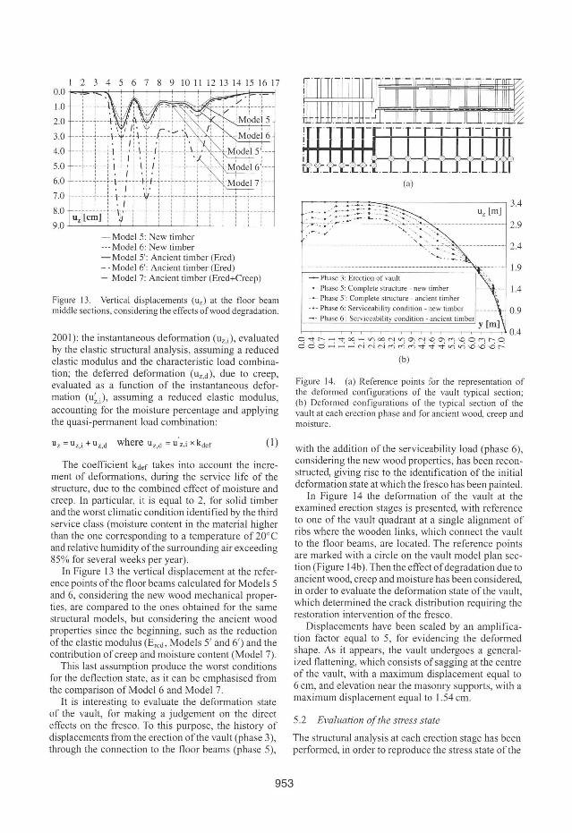
Figure 13. Vertical displacements (uz) at the floor beam middle sections, considering the effects ofwood degradation.
2001): the instantaneous deformation (Uz,i), evaluated by the elastic structural analysis, assuming a reduced elastic modulus and the characteristic load combination; the deferred deformation (Uz.d), due to creep, evaluated as a function of the instantaneous deformation (u~), assuming a reduced elastic modulus, accounting for the moisture percentage and applying the quasl-permanent load combination:
Uz = uz,i + uz,d where uz,d = U'z,i x kdef (I)
The coefficient ~ef takes into account the increment of deformations, during the service life of the structure, due to the combined effect of moisture and creep. In particular, it is equal to 2, for solid timber and the worst climatic condition identified by the third service class (moisture content in the material higher than the one corresponding to a temperature of 200 e and relative humidity ofthe surrounding air exceeding 85% for severa I weeks per year).
In Figure 13 the vertical displacement at the reference points ofthe floor beams calculated for Models 5 and 6, considering the new wood mechanical properties, are compared to the ones obtained for the same structural models, but considering the ancient wood properties since the beginning, such as the reduction ofthe elastic modulus (Ered , Models 5' and 6' ) and the contribution of creep and moisture content (Model 7).
This last assumption produce the worst conditions for the deflection state, as it can be emphasised from the comparison ofModel 6 and Model 7.
It is interesting to evaluate the deformation state of the vault, for making a judgement on the direct effects on the fresco. To this purpose, the history of displacements from the erection ofthe vault (phase 3), through the connection to the floor beams (phase 5),
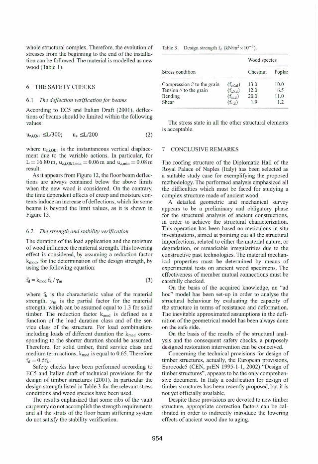
(a)
-------------------------------=-,-~-.-~ :-..: '" ------------", -... - -.... ', ' ....... ::>.
- Phase 3: Erection of vault
- . - Phase 5: Complete structure - new timber _ _ o Phase 5'; Complete slructure - aneient timber
- . - Phase 6: Serviceability condition - new timber
-" Phase 6'; Serviceability condition - ancient timber
2.4
1.9
1.4
0.9
y [m]
O~~~~~~~~N~~N~~~~O~~O°.4 OOO---NNN~M~~~~~~000~
(b)
Figure 14. (a) Reference points for the representation of the deformed configurations of the vault typical section; (b) Deformed configurations of the typical section of the vault at each erection phase and for ancient wood, creep and mOlsture.
with the addition of the serviceability load (phase 6), considering the new wood properties, has been reconstructed, giving rise to the identification of the initial deformation state at which the fresco has been painted.
In Figure 14 the deformation of the vault at the examined erection stages is presented, with reference to one of the vault quadrant at a single alignment of ribs where the wooden links, which connect the vault to the floor beams, are located . The reference points are marked with a circle on the vault model plan section (Figure 14b). Then the effect of degradation due to ancient wood, creep and moisture has been considered, in order to evaluate the deformation state of the vault which determined the crack distribution requiring th~ restoration intervention of the fresco. . Displacements have been scaled by an amplifica
tlOn factor equal to 5, for evidencing the deformed shape. As it appears, the vault undergoes a generalIzed flattening, which consists of sagging at the centre of the vault, with a maximum displacement equal to 6 cm, and elevation near the masonry supports, with a maximum displacement equal to 1.54 cm.
5.2 Evaluation ofthe stress state
The structuraI analysis at each erection stage has been performed, in order to reproduce the stress state of the
953
whole structural complex. Therefore, the evolution of Table 3. Design strength fd (kN/m2 x 10- 3 ).
stresses from the beginning to the end of the installa-tion can be fo llowed. The material is modelled as new Wood species
wood (Table 1).
6 THE SAFETY CHECKS
6. 1 The deflection verification for beams
According to EC5 and ltalian Draft (200 I) , deflections ofbeams should be limited within the following values:
UZ,i,Qkl ~/300; Uz ~/200 (2)
where Uz, i,Qk l is the instantaneous vertical displacement due to the variable actions. In particular, for L = 16.80 m, Uz,i ,Qkl ,min = 0.06 m and Uz,min = 0.08 m result.
As it appears from Figure 12, the floor beam deflections are always contained below the above limits when the new wood is considered. On the contrary, the time dependent effects of creep and moisture contents induce an increase of deflections, which for some beams is beyond the limit values, as it is shown in Figure 13.
6.2 The strength and stability verification
The duration of the load application and the moisture ofwood influence the material strength. This lowering effect is considered, by assuming a reduction fac tor kmod , for the determination of the design strength, by using the fo llowing equation:
(3)
where fk is the characteristic value of the material strength, Ym is the partial factor for the material strength, which can be assumed equal to 1.3 for solid timber. The reduction facto r kmod is defined as a function of the load duration class and of the service class of the structure. For load combinations including loads of different duration the kmod corresponding to the shorter duration should be assumed. Therefore, for solid timber, third service class and medium term actions, kmod is equal to 0.65. Therefore fd =0.5fk ·
Safety checks have been performed according to EC5 and Italian draft of technical provisions for the design of timber structures (200 I). In particular the design strength listed in Table 3 for the relevant stress conditions and wood species have been used.
The results enphasized that some ribs of the vault carpentry do not accomplish the strength requirements and ali the struts of the floor beam stiffening system do not satisfy the stability verifica tion.
Stress condition Chestnut Poplar
Compression 11 to lhe grain (fc,O,d) 13.0 10.0 Tension 11 to the grain (fl,o,d) 12.0 6.5 Bending (fm,d) 20.0 11.0 Shear (fv,d) 1.9 1.2
The stress state in ali the other structural elements is acceptable.
7 CONCLUSIVE REMARKS
The roofing structure of the Diplomatic Hall of the Royal Palace of Naples (Italy) has been selected as a suitable study case for exemplifying the proposed methodology. The performed analysis emphasized ali the difficulties which must be faced for studying a complex structure made of ancient wood.
A detailed geometric and mechanical survey appears to be a preliminary and obligatory phase fo r the structural analysis of ancient constructions, in order to achieve the structural characterization. This operation has been based on meticulous in situ investigations, aimed at pointing out ali the structural imperfections, related to either the material nature, or degradation, or remarkable irregularities due to the constructive past technologies. The material mechanical properties must be determined by means of experimental tests on ancient wood specimens. The effectiveness of member mutual connections must be carefully checked.
On the basis of the acquired knowledge, an "ad hoc" model has been set-up in order to analyse the structural behaviour by evaluating the capacity of the structure in terms of resistance and deformation. The inevitable approximated assumptions in the definition ofthe geometrical model has been always done on the safe side.
On the basis of the results of the structural analysis and the consequent safety checks, a purposely designed restoration intervention can be conceived.
Concerning the technical provisions for design of timber structures, actually, the European provisions, Eurocode5 (CEN, prEN 1995-1-1, 2002) "Design of timber structures", appears to be the only comprehensive document. In ltaly a codification for design of timber structures has been recently proposed, but it is not yet officially available.
Despite these provisions are devoted to new timber structure, appropriate correction factors can be calibrated in order to indirectly introduce the lowering effects of ancient wood due to aging.
954
ACKNOWLEDGEMENT
Authors would like to acknowledge the Superintendence for Cultural Heritage of Naples (arch. Enrico Guglielmo), which has the authority on all the activities developed inside the Royal Palace ofNaples, and which entrusted the structural check for the retrofitting ofthe Diplomatic Hall.
REFERENCES
Balzano, M. and La Morte, G. 2001. Comportamento flessionale di travi in legno in presenza di imperfezioni (Bending behaviour of wooden beams accounting for imperfections), Graduation thesis, Napoli, ltalia, Tutors: Mazzolani F.M., Calderoni B. and De Matteis G.
CEN (European Communities for Standardisation), Final draft prEN 1995-1-12002. Eurocode 5: Design oftimber structures - Part 1-1: General rules - General rules and rules for buildings.
CLEAN ed. 1996. Manuale dei recupero delle antiche tecniche costruttive napoletane dai '300 ali '800 (Manual of
955
lhe ancient constructive techniques in Naples since '300 to '800). Napoli.
Giordano, G. 1989. Tecnica delle Costruzioni in legno (Wooden structure engineering). HOEPLl ed. , Milano, ltalia.
Giubileo, C. 2002. Comportamento di travi in legno antico: analisi teorico sperimentale (Behaviour of ancient wood beams: theoretical and experimental investigations) , Graduation thesis, Napoli , [talia, Tutors: Mazzolani F. M. , Calderoni B. and De Matteis G ..
Marzo, A. 2003. Metodologie di analisi teorico-sperimentali di strutture complesse in legno antico (Methodologiesfor the theoretical-experimen/al analysis of complex wooden s/ruclures), Graduation thesis, Napoli, Ilalia. Tutors: Mazzolani F. M. , Faggiano B. and Giubileo c..
Mazzolani, F.M., Calderoni, B., De Matteis, G. and Giubileo, C. 2004. Experimental analysis of ancient wooden beams for flexural and shear failure. Proceedings ofthe 4th lnternational Seminar "S/ructural analysis ofhistorical constructions", Padova, November 10-13.
Uzielli, L., Bonamini, G., Noferi, M. and Togni , M. 2001.11 manuale dellegno strutturale vaI. 1 - lspezione e diagnosi in opera (Manual ofthe structural wood, vol.1 - lnspection and diagnosis in situ), Mancosu ed., Roma, ltalia.