Embed Size (px)
Citation preview
Methodical spatial databasedesign with topological polygon
structures
Mazimpaka Jean Damascene
March, 2009

Methodical spatial database design withtopological polygon structures
by
Mazimpaka Jean Damascene
Thesis submitted to the International Institute for Geo-information Science andEarth Observation in partial fulfilment of the requirements for the degree inMaster of Science in Geoinformatics.
Degree Assessment Board
Thesis advisor Dr. J. MoralesDr. Ir. R.A. de By
Thesis examiners Prof. Dr. M.J. KraakDr. A. Wombacher
INTERNATIONAL INSTITUTE FOR GEO-INFORMATION SCIENCE AND EARTH OBSERVATION
ENSCHEDE, THE NETHERLANDS

Disclaimer
This document describes work undertaken as part of a programme of study atthe International Institute for Geo-information Science and Earth Observation(ITC). All views and opinions expressed therein remain the sole responsibilityof the author, and do not necessarily represent those of the institute.
Abstract
With the current advances in Information and Communication Technol-ogy (ICT), we see a problem shift from data availability to data mainte-nance. Today’ s best approach to managing huge amounts of data is to usea Database Management System (DBMS). The field of Geographic Infor-mation Systems (GIS) makes no exception. However, in GIS the problembecomes much more complex due to the nature of spatial data. For spatialdata, a mechanism is needed to capture the semantics of spatial objects,and an improved methodology for spatial database design is needed to sim-plify the design complicated by the semantics of spatial objects and an in-creasing number of standards and implementation platforms.
The main objective in this research is to develop primitives for modellingcollections of area features that display topological dependencies, and todevelop a transformational database design process for the realisation ofarea feature topology in spatial databases. In this respect, modelling prim-itives have been developed by extending the Unified Modelling Language(UML). A semi-automatic transformation process has been developed withtwo transformation steps. The first step uses transformation definitionsthat have been developed using the programming environment of Enter-prise Architect. The second step uses a custom tool that has been developedusing Java programming language.
The modelling primitives are used in a modelling tool such as EnterpriseArchitect to build a conceptual model of the database. The transforma-tion process transforms design results between schema levels. Firstly, theconceptual schema is transformed to logical schema for an implementationof choice between spaghetti and topological models. Secondly, the logicalschema is transformed to physical schema in which the final result is atext file containing SQL statements for implementing the database in Post-greSQL/PostGIS Database Management System.
KeywordsSpatial database, area features, topology, UML, modelling primitives, MDA,design, XMI
i

Abstract
ii

Acknowledgements
I take this opportunity to thank the Almighty God for his blessings to me on each dayof my life.
I thank my first supervisor Dr. Javier Morales. Your guidance showed me the way inthe world of scientific research. I extend my gratitude to my second supervisor Dr. Rolfde By. Your patience when I could not easily understand your comments encouragedme. You have inspired me to build my concrete ideas from abstract concepts.
I express my gratitude to CGIS-NUR and the Netherlands Government though NUFFICfunding for their financial support.
My thanks also go to Karangwa Charles. I can not forget your contribution in makingit possible for me to pursue my studies, and the orientation you gave me in my studies.
Finally, I am so grateful to my friends at ITC, especially my GFM2 classmates for theircooperation and encouragement, and to all other people who have supported me di-rectly or indirectly throughout my studies.
May God bless you all.
iii

Acknowledgements
iv
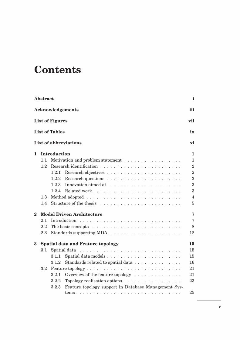
Contents
Abstract i
Acknowledgements iii
List of Figures vii
List of Tables ix
List of abbreviations xi
1 Introduction 11.1 Motivation and problem statement . . . . . . . . . . . . . . . . . 11.2 Research identification . . . . . . . . . . . . . . . . . . . . . . . . 2
1.2.1 Research objectives . . . . . . . . . . . . . . . . . . . . . . 21.2.2 Research questions . . . . . . . . . . . . . . . . . . . . . . 31.2.3 Innovation aimed at . . . . . . . . . . . . . . . . . . . . . 31.2.4 Related work . . . . . . . . . . . . . . . . . . . . . . . . . . 3
1.3 Method adopted . . . . . . . . . . . . . . . . . . . . . . . . . . . . 41.4 Structure of the thesis . . . . . . . . . . . . . . . . . . . . . . . . 5
2 Model Driven Architecture 72.1 Introduction . . . . . . . . . . . . . . . . . . . . . . . . . . . . . . 72.2 The basic concepts . . . . . . . . . . . . . . . . . . . . . . . . . . 82.3 Standards supporting MDA . . . . . . . . . . . . . . . . . . . . . 12
3 Spatial data and Feature topology 153.1 Spatial data . . . . . . . . . . . . . . . . . . . . . . . . . . . . . . 15
3.1.1 Spatial data models . . . . . . . . . . . . . . . . . . . . . . 153.1.2 Standards related to spatial data . . . . . . . . . . . . . . 16
3.2 Feature topology . . . . . . . . . . . . . . . . . . . . . . . . . . . . 213.2.1 Overview of the feature topology . . . . . . . . . . . . . . 213.2.2 Topology realisation options . . . . . . . . . . . . . . . . . 233.2.3 Feature topology support in Database Management Sys-
tems . . . . . . . . . . . . . . . . . . . . . . . . . . . . . . . 25
v
Contents
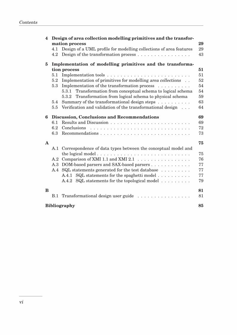
4 Design of area collection modelling primitives and the transfor-mation process 294.1 Design of a UML profile for modelling collections of area features 294.2 Design of the transformation process . . . . . . . . . . . . . . . . 43
5 Implementation of modelling primitives and the transforma-tion process 515.1 Implementation tools . . . . . . . . . . . . . . . . . . . . . . . . . 515.2 Implementation of primitives for modelling area collections . . 525.3 Implementation of the transformation process . . . . . . . . . . 54
5.3.1 Transformation from conceptual schema to logical schema 545.3.2 Transformation from logical schema to physical schema 59
5.4 Summary of the transformational design steps . . . . . . . . . . 635.5 Verification and validation of the transformational design . . . 64
6 Discussion, Conclusions and Recommendations 696.1 Results and Discussion . . . . . . . . . . . . . . . . . . . . . . . . 696.2 Conclusions . . . . . . . . . . . . . . . . . . . . . . . . . . . . . . 726.3 Recommendations . . . . . . . . . . . . . . . . . . . . . . . . . . . 73
A 75A.1 Correspondence of data types between the conceptual model and
the logical model . . . . . . . . . . . . . . . . . . . . . . . . . . . . 75A.2 Comparison of XMI 1.1 and XMI 2.1 . . . . . . . . . . . . . . . . 76A.3 DOM-based parsers and SAX-based parsers . . . . . . . . . . . . 77A.4 SQL statements generated for the test database . . . . . . . . . 77
A.4.1 SQL statements for the spaghetti model . . . . . . . . . . 77A.4.2 SQL statements for the topological model . . . . . . . . . 79
B 81B.1 Transformational design user guide . . . . . . . . . . . . . . . . 81
Bibliography 85
vi
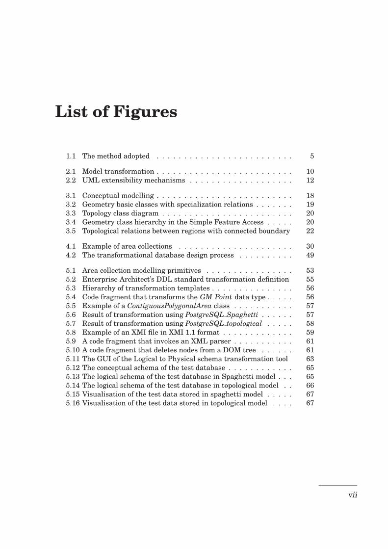
List of Figures
1.1 The method adopted . . . . . . . . . . . . . . . . . . . . . . . . . 5
2.1 Model transformation . . . . . . . . . . . . . . . . . . . . . . . . . 102.2 UML extensibility mechanisms . . . . . . . . . . . . . . . . . . . 12
3.1 Conceptual modelling . . . . . . . . . . . . . . . . . . . . . . . . . 183.2 Geometry basic classes with specialization relations . . . . . . . 193.3 Topology class diagram . . . . . . . . . . . . . . . . . . . . . . . . 203.4 Geometry class hierarchy in the Simple Feature Access . . . . . 203.5 Topological relations between regions with connected boundary 22
4.1 Example of area collections . . . . . . . . . . . . . . . . . . . . . 304.2 The transformational database design process . . . . . . . . . . 49
5.1 Area collection modelling primitives . . . . . . . . . . . . . . . . 535.2 Enterprise Architect’s DDL standard transformation definition 555.3 Hierarchy of transformation templates . . . . . . . . . . . . . . . 565.4 Code fragment that transforms the GM Point data type . . . . . 565.5 Example of a ContiguousPolygonalArea class . . . . . . . . . . . 575.6 Result of transformation using PostgreSQL Spaghetti . . . . . . 575.7 Result of transformation using PostgreSQL topological . . . . . 585.8 Example of an XMI file in XMI 1.1 format . . . . . . . . . . . . . 595.9 A code fragment that invokes an XML parser . . . . . . . . . . . 615.10 A code fragment that deletes nodes from a DOM tree . . . . . . 615.11 The GUI of the Logical to Physical schema transformation tool 635.12 The conceptual schema of the test database . . . . . . . . . . . . 655.13 The logical schema of the test database in Spaghetti model . . . 655.14 The logical schema of the test database in topological model . . 665.15 Visualisation of the test data stored in spaghetti model . . . . . 675.16 Visualisation of the test data stored in topological model . . . . 67
vii

List of Figures
viii
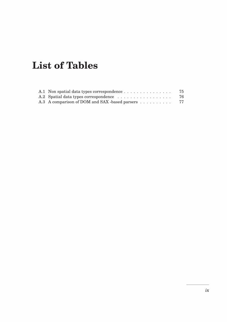
List of Tables
A.1 Non spatial data types correspondence . . . . . . . . . . . . . . . 75A.2 Spatial data types correspondence . . . . . . . . . . . . . . . . . 76A.3 A comparison of DOM and SAX -based parsers . . . . . . . . . . 77
ix

List of Tables
x
List of abbreviations
API Application Programming Interface
CIM Computation Independent Model
CORBA Common Object Request Broker Architecture
DBMS Database Management System
DDL Data Definition Language
DML Data Manipulation Language
DOM Document Object Model
DTD Document Type Definition
GEOS Geometry Engine - Open Source
GIS Geographic Information System
HTML HyperText Markup Language
IEC International Electrotechnical Commission
ISO International Standards Organization
JDK Java Development Kit
JTS Java Topology Suite
MDA Model Driven Architecture
MOF Meta Object Facility
OCL Object Constraint Language
OGC Open Geospatial Consortium
OLE/COM Object Linking and Embedding/Component Object Model
OMG Object Management Group
PIM Platform Independent Model
PSM Platform Specific Model
xi

List of abbreviations
SAX Simple API for XML
SFA Simple Feature Access
SQL Structured Query Language
UML Unified Modeling Language
XMI XML Metadata Interchange
XML eXtensible Markup Language
xii
Chapter 1
Introduction
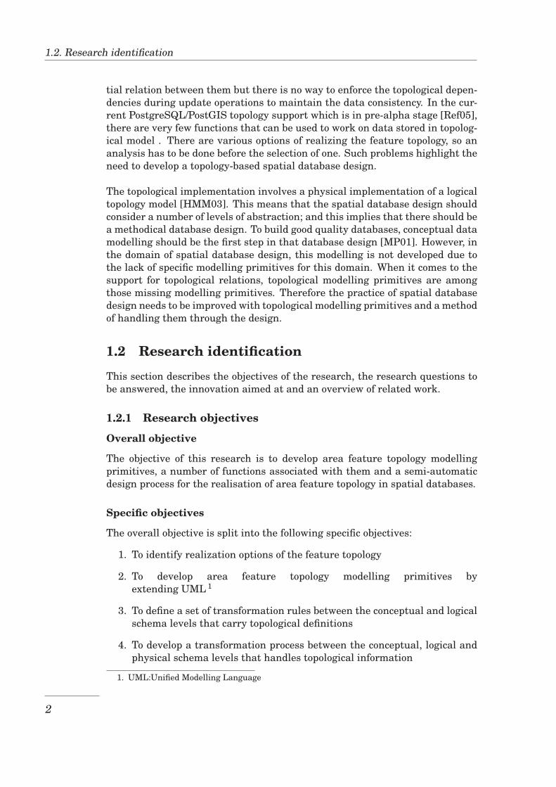
1.1 Motivation and problem statement
A database is a very large, structured and integrated collection of data. ADatabase Management System (DBMS) is a software system that allows creat-ing and managing databases. A DBMS has many advantages such as providinga unified storage, management and control for large volume of data and provid-ing a standard mechanism for accessing data.
A spatial database is a special type of database which, in addition to storing thecommon attributes values of the objects, stores data about their geographicallocation and shape and provides functions to work on these data. The repre-sentations of spatial objects in the database have specific characteristics whichmake their management and manipulation complex. Among such characteris-tics are the topological spatial relations, which are spatial relations that are notaffected by transformations like rotation and scaling [ECF94].
While working with data in a spatial database to display, process or analysespatial information, users are often interested in objects that have a certainspatial relationship between them. The spatial relations are categorized intotopological relations, metric relations and relations concerning the partial andtotal order of spatial objects [EF91]. Furthermore, topological spatial relationscan be area feature topological relations, linear feature topological relations, orpoint feature topological relations depending on the type of the real world ob-ject represented. Topological relations are involved in several problems rangingfrom simple to advanced cases. A simple case is like, instead of being interestedin all hospitals of a country, people may be interested in only hospitals built inone particular province. A much more advanced case is like the requirementto enforce topological dependencies between features in a collection, such asuniversity campuses should not overlap, or there can not be gaps between theprovinces of a country.
The support for the feature topology in open source spatial database platformsis only elementary. As an example, in PostgreSQL/PostGIS, it is possible tocheck if the representations of two spatial objects have a certain topological spa-
1
1.2. Research identification
tial relation between them but there is no way to enforce the topological depen-dencies during update operations to maintain the data consistency. In the cur-rent PostgreSQL/PostGIS topology support which is in pre-alpha stage [Ref05],there are very few functions that can be used to work on data stored in topolog-ical model . There are various options of realizing the feature topology, so ananalysis has to be done before the selection of one. Such problems highlight theneed to develop a topology-based spatial database design.
The topological implementation involves a physical implementation of a logicaltopology model [HMM03]. This means that the spatial database design shouldconsider a number of levels of abstraction; and this implies that there should bea methodical database design. To build good quality databases, conceptual datamodelling should be the first step in that database design [MP01]. However, inthe domain of spatial database design, this modelling is not developed due tothe lack of specific modelling primitives for this domain. When it comes to thesupport for topological relations, topological modelling primitives are amongthose missing modelling primitives. Therefore the practice of spatial databasedesign needs to be improved with topological modelling primitives and a methodof handling them through the design.
1.2 Research identification
This section describes the objectives of the research, the research questions tobe answered, the innovation aimed at and an overview of related work.
1.2.1 Research objectives
Overall objective
The objective of this research is to develop area feature topology modellingprimitives, a number of functions associated with them and a semi-automaticdesign process for the realisation of area feature topology in spatial databases.
Specific objectives
The overall objective is split into the following specific objectives:
1. To identify realization options of the feature topology
2. To develop area feature topology modelling primitives byextending UML 1
3. To define a set of transformation rules between the conceptual and logicalschema levels that carry topological definitions
4. To develop a transformation process between the conceptual, logical andphysical schema levels that handles topological information
1. UML:Unified Modelling Language
2
Chapter 1. Introduction
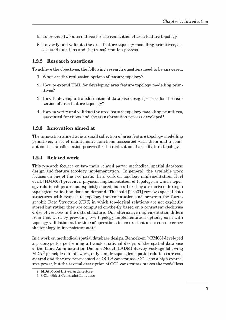
5. To provide two alternatives for the realization of area feature topology
6. To verify and validate the area feature topology modelling primitives, as-sociated functions and the transformation process
1.2.2 Research questions
To achieve the objectives, the following research questions need to be answered:
1. What are the realization options of feature topology?
2. How to extend UML for developing area feature topology modelling prim-itives?
3. How to develop a transformational database design process for the real-ization of area feature topology?
4. How to verify and validate the area feature topology modelling primitives,associated functions and the transformation process developed?
1.2.3 Innovation aimed at
The innovation aimed at is a small collection of area feature topology modellingprimitives, a set of maintenance functions associated with them and a semi-automatic transformation process for the realization of area feature topology.
1.2.4 Related work
This research focuses on two main related parts: methodical spatial databasedesign and feature topology implementation. In general, the available workfocuses on one of the two parts. In a work on topology implementation, Hoelet al. [HMM03] present a physical implementation of topology in which topol-ogy relationships are not explicitly stored, but rather they are derived during atopological validation done on demand. Theobald [The01] reviews spatial datastructures with respect to topology implementation and presents the Carto-graphic Data Structure (CDS) in which topological relations are not explicitlystored but rather they are computed on-the-fly based on a consistent clockwiseorder of vertices in the data structure. Our alternative implementation differsfrom that work by providing two topology implementation options, each withtopology validation at the time of operations to ensure that users can never seethe topology in inconsistent state.
In a work on methodical spatial database design, Bennekom [vBM08] developeda prototype for performing a transformational design of the spatial databaseof the Land Administration Domain Model (LADM) Survey Package followingMDA 2 principles. In his work, only simple topological spatial relations are con-sidered and they are represented as OCL 3 constraints. OCL has a high expres-sive power, but the textual description of OCL constraints makes the model less
2. MDA:Model Driven Architecture3. OCL: Object Constraint Language
3
1.3. Method adopted
understandable by the model readers, and writing OCL constraints requires thedatabase designer to master OCL syntax. It is desirable to restrict the use ofOCL constraints to the cases where they are the only possible option. More-over, we need a general transformation process applicable to different domains.Wang et al. [WR07] present a method to extend geographic data modelling alsotaking into account topological spatial relations. This method uses a ConstraintDecision Table (CDT) to store the topological integrity constraints. The prob-lems of this approach are linked to the separation of the constraints from theUML conceptual schema and the mastery required for defining the constraints.Our method differs from that work by keeping topological spatial relations asan integral part of the UML conceptual schema and providing the database de-signer with a more user friendly way of representing these relations; which isa small collection of topological modelling constructs for which the transforma-tion towards implementation is clear. A more general difference of this projectfrom other related work is that it treats topological dependencies between fea-tures within a collection of features rather than topological relations betweensimple features treated by the related work.
1.3 Method adopted
The method that will be adopted in this project is based on the core workflowsof the Unified Software Development Process which is described in [JBR99].This method comprises five core workflows: requirements definition, analysis,design, implementation, and testing. As the project starts by exploring theavailable possibilities, then developing a transformation process and a tool usedin that transformation and ending with testing, these activities fit well in thoseworkflows as follows:
1. Requirements definition and analysisIn this phase a literature review will be done to explain fundamental con-cepts, and to identify realisation options for the feature topology.
2. DesignThe activities in this phase are:
• to propose a number of topological classes for modelling area features:describe each class, a primitive for modelling it and a set of mainte-nance functions to work on it,
• to describe the transformational design of spatial database accordingto MDA principles by:
– describing the conceptual, logical, and physical schema,– describing transformation rules, that apply also to the proposed
primitives, for mapping between schema levels.
3. ImplementationIn this phase, programming will be done for:
4
Chapter 1. Introduction
• the creation of the area feature topology modelling primitives andassociated maintenance functions,
• the implementation of the transformational database design processfollowing MDA principles, and this for two of the feature topologyrealisation options identified in the first phase.
4. TestingIn this phase, a test case will be prepared with real world data that can bemodelled as collections of area features. The test case will be used to testthe topology modelling primitives, associated functions and the transfor-mation process.
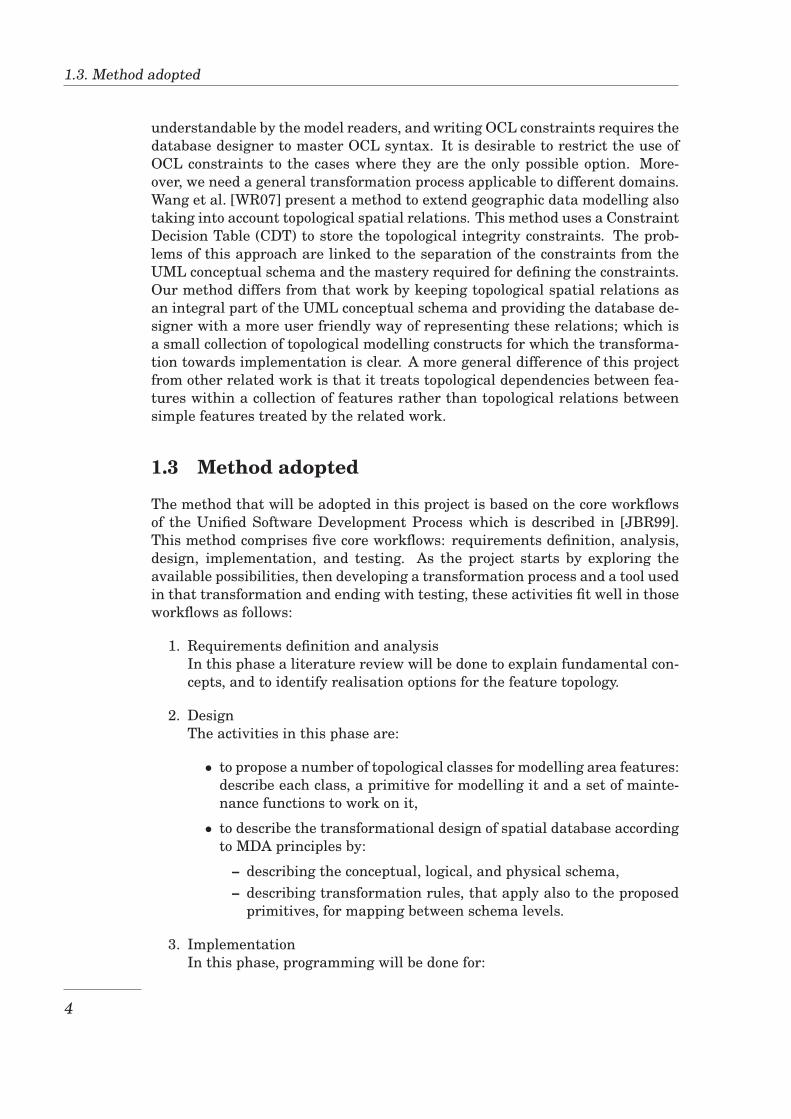
In parallel to all these activities the documentation task will be done. Themethod that will be followed in the research is illustrated in Figure 1.1 below,showing the phases and deliverables from each phase which serve as input tothe next phase.
Figure 1.1: The method adopted (adapted from [AN05], p.36)
1.4 Structure of the thesis
Based on the method adopted in the research, this thesis is organized in sixchapters as follows:
Chapter 1 describes the motivation to do this research, states the problem,research objectives and questions, and describes the method adopted inthe research.
Chapter 2 discusses the Model Driven Architecture (MDA), which is the tech-nique that the transformational design process developed in the researchfollows. The chapter discusses MDA by presenting underlying basic con-cepts and some standards that support MDA.
Chapter 3 discusses the concepts of spatial data and feature topology on whichthe transformational design will be applied. Some standards related to
5
1.4. Structure of the thesis
spatial data are briefly presented and identified feature topology realisa-tion options are presented.
Chapter 4 contains the design part of the project. The chapter describes twodesign parts: the design of primitives for modelling collections of areafeatures and the design of a transformation process.
Chapter 5 contains the implementation and testing parts of the project. Boththe creation of the modelling primitives and the implementation of thetransformation process are presented. The testing that has been done toverify and validate the developed modelling primitives and transforma-tion process is also presented.
Chapter 6 presents and discusses the results of the project execution. Thechapter also presents the conclusions drawn and the recommendationsmade for future improvement of the modelling primitives and the trans-formation process.
6
Chapter 2
Model Driven Architecture
This research intends to provide an improved method for spatial database de-sign. The method should be replicable to contribute to complexity managementthrough a separation of concerns. That is, the method should separate the con-cerns at the conceptual level from the concerns at the implementation level,thus allowing the artefacts at the conceptual level to be reused for differenttargeted implementations. Among several available methods of system devel-opment, the Model Driven Architecture achieves this separation of concerns. Atthe conceptual level, the concepts are modelled with focus on the data contentwithout caring about the implementation issues. After a short introduction thatdefines MDA, this chapter presents some concepts (Section 2.2) and standards(Section 2.3) which are at the core of MDA.
2.1 Introduction
The Model Driven Architecture (MDA) has been introduced by the Object Man-agement Group (OMG). MDA is an approach to software development usingmodels. In the MDA framework, a software system is produced through a se-ries of model transformations aided by a modelling tool. As stated in [MM03],“The Model-Driven Architecture starts with the well-known and long estab-lished idea of separating the specification of the operation of a system fromthe details of the way that system uses the capabilities of its platform. MDAprovides an approach for, and enables tools to be provided for:
• specifying a system independently of the platform that supports it,
• specifying platforms,
• choosing a particular platform for the system, and
• transforming the system specification into one for a particular platform
The three primary goals of MDA are portability, interoperability and reusabilitythrough architectural separation of concerns.”
7
2.2. The basic concepts
2.2 The basic concepts
The MDA guide [MM03] defines the concepts that are fundamental to MDA.The definitions of some of those concepts are presented in this section.
System
A system is a collection of components that together perform a certain function.The system may include software, hardware and people. The discussion in thisdocument focuses on the software component within the system.
Model
A model of a system is a representation of the system that describes it and itsenvironment for a certain purpose. A model of a system is sometimes referredto as a view of the system. A model is often presented as a combination ofdrawings and text.
Metamodel
A metamodel is an abstraction that describes a model. From data to metamodel,there is an increasing abstraction; where the data are raw facts, a model is anabstraction of data, metadata being information about a model and metamodelbeing an abstraction of metadata [BP98].
Model-Driven
MDA is an approach to system development, which is based on models. It ismodel-driven because it specifies how to use models to ease the understanding,design, construction, deployment, operation and maintenance of a system.
Architecture
As stated in [MM03], “the architecture of a system is a specification of the partsand connectors of the system and the rules for the interactions of the partsusing the connectors.” The Model-Driven Architecture specifies certain kindsof models to be used, how those models may be made ready for use, and therelationships of the different kinds of models.
Platform
A platform is a set of components and technologies that provide to any sup-ported application a set of functionalities through interfaces while they hide tothe application the implementation of those functionalities.
8
Chapter 2. Model Driven Architecture
Viewpoint
OMG defines a viewpoint on a system as a level of suppressing selected detailwhen specifying that system, in order to focus on particular concerns withinthat system [MM03]. This suppression of detail is achieved using a set of con-cepts and rules. The concepts and rules may be considered to form a viewpointlanguage. MDA specifies three viewpoints on a system; a computation inde-pendent viewpoint, a platform independent viewpoint and a platform specificviewpoint.
MDA Viewpoints and models
Computation Independent Viewpoint and Model
The Computation Independent Viewpoint (CIV) focuses on the system require-ments and its environment. In this viewpoint, the details of the structure ofthe system and the processing carried out by the system are hidden or not yetdetermined. The Computation Independent Model (CIM) of a system is its viewfrom the computation independent viewpoint. A CIM does not show details ofthe structure of a system. A terminology that is familiar to the people in thedomain in question is used in the specification of a CIM. For this, a CIM issometimes called a domain model.
Platform Independent Viewpoint and Model
The Platform Independent Viewpoint (PIV) focuses on the operation of a systemwhile hiding the details imposed by a particular platform. The Platform Inde-pendent Model (PIM) of a system is its view from the platform independentviewpoint.
Platform Specific Viewpoint and Model
The Platform Specific Viewpoint (PSV) considers the concepts available at theplatform independent viewpoint but tailored with the detail imposed by a spe-cific platform. The Platform Specific Model (PSM) of a system is the view ofthat system from a platform specific viewpoint.
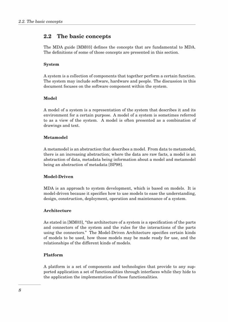
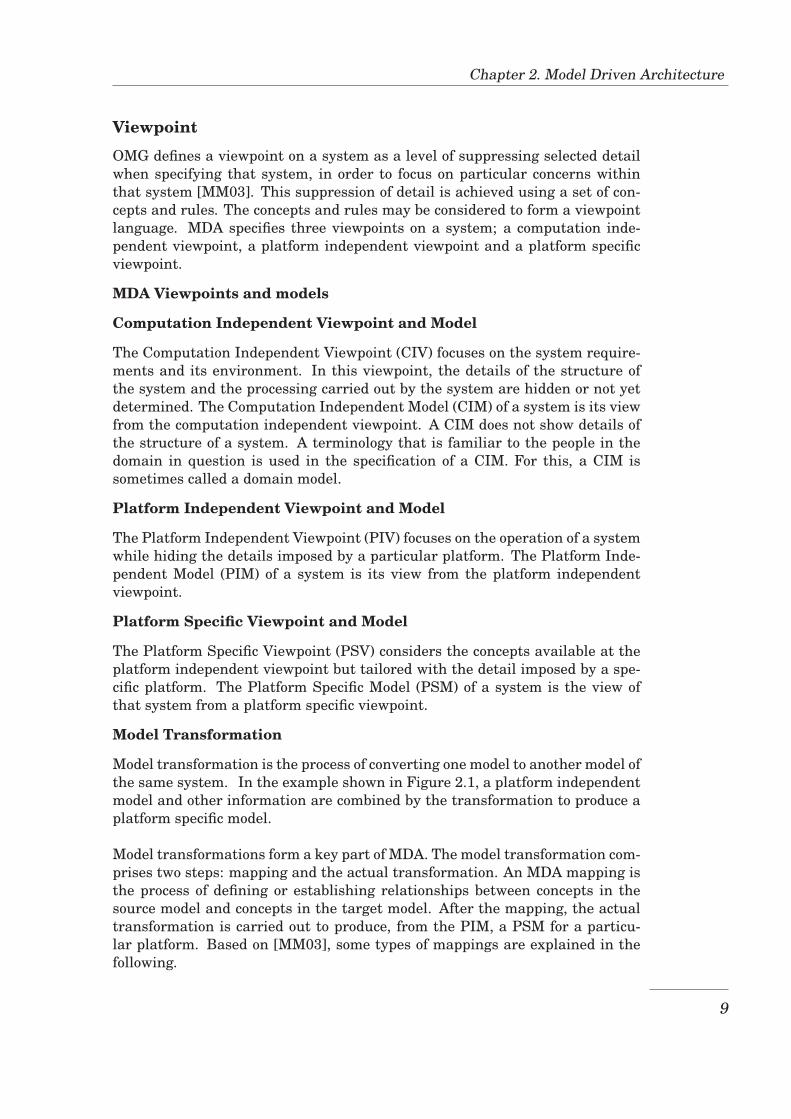
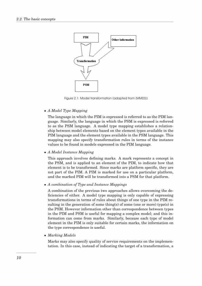
Model Transformation
Model transformation is the process of converting one model to another model ofthe same system. In the example shown in Figure 2.1, a platform independentmodel and other information are combined by the transformation to produce aplatform specific model.
Model transformations form a key part of MDA. The model transformation com-prises two steps: mapping and the actual transformation. An MDA mapping isthe process of defining or establishing relationships between concepts in thesource model and concepts in the target model. After the mapping, the actualtransformation is carried out to produce, from the PIM, a PSM for a particu-lar platform. Based on [MM03], some types of mappings are explained in thefollowing.
9
2.2. The basic concepts
Figure 2.1: Model transformation (adapted from [MM03])
• A Model Type Mapping
The language in which the PIM is expressed is referred to as the PIM lan-guage. Similarly, the language in which the PSM is expressed is referredto as the PSM language. A model type mapping establishes a relation-ship between model elements based on the element types available in thePIM language and the element types available in the PSM language. Thismapping may also specify transformation rules in terms of the instancevalues to be found in models expressed in the PIM language.
• A Model Instance Mapping
This approach involves defining marks. A mark represents a concept inthe PSM, and is applied to an element of the PIM, to indicate how thatelement is to be transformed. Since marks are platform specific, they arenot part of the PIM. A PIM is marked for use on a particular platform,and the marked PIM will be transformed into a PSM for that platform.
• A combination of Type and Instance Mappings
A combination of the previous two approaches allows overcoming the de-ficiencies of either. A model type mapping is only capable of expressingtransformations in terms of rules about things of one type in the PIM re-sulting in the generation of some thing(s) of some (one or more) type(s) inthe PSM. However information other than correspondence between typesin the PIM and PSM is useful for mapping a complex model; and this in-formation can come from marks. Similarly, because each type of modelelement in the PIM is only suitable for certain marks, the information onthe type correspondence is useful.
• Marking Models
Marks may also specify quality of service requirements on the implemen-tation. In this case, instead of indicating the target of a transformation, a
10
Chapter 2. Model Driven Architecture
mark may simply provide a requirement on the target. The transforma-tion will then choose a target suitable for that requirement. Marks mayneed to be structured or constrained to be properly used. Also, instead ofbeing supplied by a mapping, a set of marks may be specified by a markmodel, which is independent of any particular mapping.
• Templates
As defined in [MM03], “templates are parameterized models that specifyparticular kinds of transformations.” A mapping may include templates.Templates can be used in rules in model type mapping for transforminga pattern of model elements into another pattern of model elements. Aset of marks can be associated with a template to indicate instances in amodel which should be transformed according to that template.
• Mapping Language
A mapping is specified using some language to describe a transformationof one model to another. The description may be in natural language,an algorithm or in a model mapping language (a language designed forspecifying model mappings).
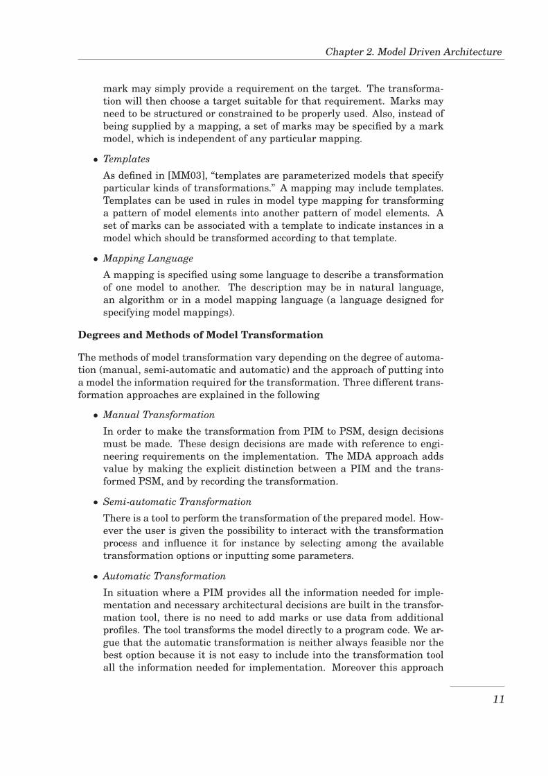
Degrees and Methods of Model Transformation
The methods of model transformation vary depending on the degree of automa-tion (manual, semi-automatic and automatic) and the approach of putting intoa model the information required for the transformation. Three different trans-formation approaches are explained in the following
• Manual Transformation
In order to make the transformation from PIM to PSM, design decisionsmust be made. These design decisions are made with reference to engi-neering requirements on the implementation. The MDA approach addsvalue by making the explicit distinction between a PIM and the trans-formed PSM, and by recording the transformation.
• Semi-automatic Transformation
There is a tool to perform the transformation of the prepared model. How-ever the user is given the possibility to interact with the transformationprocess and influence it for instance by selecting among the availabletransformation options or inputting some parameters.
• Automatic Transformation
In situation where a PIM provides all the information needed for imple-mentation and necessary architectural decisions are built in the transfor-mation tool, there is no need to add marks or use data from additionalprofiles. The tool transforms the model directly to a program code. We ar-gue that the automatic transformation is neither always feasible nor thebest option because it is not easy to include into the transformation toolall the information needed for implementation. Moreover this approach
11
2.3. Standards supporting MDA
is inflexible because it does not give the user the opportunity to influencethe transformation for specific needs.
2.3 Standards supporting MDA
OMG has adopted a number of standards, that together contribute to achiev-ing the primary goals of MDA of portability, interoperability and reusability.Some of these standards allow modelling the system conceptually without car-ing about the implementation platform hence achieving portability, others al-low packaging the model components for use in other models and/or on differ-ent software tools hence achieving also interoperability and reusability. Amongthese standards there are UML, MOF and XMI.
UML
The Unified Modelling Language (UML) is a standard modelling language thatuses object-oriented concepts for visualizing, specifying, and documenting com-ponents of software systems. Models used with MDA can be expressed usingthe UML language [MM03].
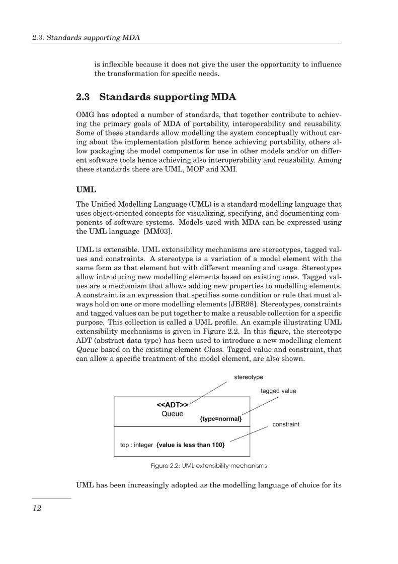
UML is extensible. UML extensibility mechanisms are stereotypes, tagged val-ues and constraints. A stereotype is a variation of a model element with thesame form as that element but with different meaning and usage. Stereotypesallow introducing new modelling elements based on existing ones. Tagged val-ues are a mechanism that allows adding new properties to modelling elements.A constraint is an expression that specifies some condition or rule that must al-ways hold on one or more modelling elements [JBR98]. Stereotypes, constraintsand tagged values can be put together to make a reusable collection for a specificpurpose. This collection is called a UML profile. An example illustrating UMLextensibility mechanisms is given in Figure 2.2. In this figure, the stereotypeADT (abstract data type) has been used to introduce a new modelling elementQueue based on the existing element Class. Tagged value and constraint, thatcan allow a specific treatment of the model element, are also shown.
Figure 2.2: UML extensibility mechanisms
UML has been increasingly adopted as the modelling language of choice for its
12
Chapter 2. Model Driven Architecture
features of extensibility, and object-oriented concepts available in many pro-gramming languages. The extensibility of UML makes it the best choice in so-phisticated applications such as Computer-Aided Design (CAD) and GeographicInformation System (GIS) which deal with complex objects with complex rela-tionships [MVC03]. Since this research treats geographic information, it usesUML for the same reasons.
OCL
The Object Constraint Language (OCL) is an extension to the UML, used toexpress constraints in UML models. UML models are generally created by us-ing UML diagrams, but there are conditions that can not be expressed in suchmodels. The combination of UML and OCL allows developing complete mod-els [WK03]. OCL is widely used to express the constraints in aforementionedUML profiles.
MOF
The Meta-Object Facility (MOF) provides a specification for implementation ofmodel repositories. As stated in [Obj05], “MOF specifies an abstract languagefor specifying, constructing, and managing technology neutral metamodels: Ametamodel is in effect an abstract language for some kind of metadata.” Toenable model transformations, MDA requires models to be expressed in a MOF-based language. Models expressed in a MOF-based language can be stored ina MOF-compliant repository, parsed and transformed by MOF-compliant tools,and rendered into XMI for transport over a network. UML is one example of aMOF-based modelling language.
XMI
XML Metadata Interchange (XMI) is an OMG standard that facilitates the ex-change of UML models in the form of XML files. It specifies how a UML modelis converted to XML file format and the XML file back to UML for model ex-change. Multiple tools can interchange the document containing model datadespite the presence of tool-specific information. XMI standard uses extensionsto hold such tool-specific information [Obj07].
13

2.3. Standards supporting MDA
14
Chapter 3
Spatial data and Featuretopology
The Model Driven Architecture(MDA) approach described in chapter 2 willwork on the concepts of spatial data and feature topology at both the concep-tual and the implementation levels. This chapter describes these concepts for abetter understanding of subsequent chapters. The concepts of spatial data aredescribed in Section 3.1 while the concepts of feature topology are described inSection 3.2.
3.1 Spatial data
Geographic data (also called spatial data) are descriptions of geographic phe-nomena including non-spatial properties such as name, and spatial propertiesincluding location and shape. The consideration of spatial properties has ledto the development of concepts and standards which are different from those ofnon-spatial data. This section reviews the concepts of spatial data, spatial datamodels and related standards that are relevant for this thesis.
3.1.1 Spatial data models
A data model is a collection of concepts for describing data. It describes the typeof data and the operations that can be performed on them. Data models can becharacterized as relational, object-oriented, or object-relational. The spatialcomponent of geographic data may include both geometry (location and shape)and topology (a kind of spatial relationship between represented objects). Therepresentation of the geometry and topology has led to new data models; thespatial data models. These data models are in two categories: entity-basedmodels and field-based models [RSV02]
Entity-based models
In the entity-based models, also referred to as object or feature-based models,the interest is on discrete geographic objects, also called entities or features.Geographic objects are classified into the following types:
15
3.1. Spatial data
• Zero-dimensional objects or points (e.g., cities)
• One-dimensional objects or linear objects (e.g., roads)
• Two-dimensional objects or area features (e.g., countries)
The object in any type may be simple or complex and the choice of the typehighly depends on the application considered. The same spatial object mayhave two different types in two different applications.
Field-based models
In a field-based (or space-based) model, each point in the space is associatedwith an attribute value, that is, the description of the geographic phenomenonis defined by a continuous function in the space. An example is the temperatureon the earth’s surface.
The spatial data models that have been presented in this section define a rep-resentation of spatial objects at an abstract level. After the data modelling, achoice will be made to what mode to use for a logical and physical representa-tion. The representation mode will be either the vector mode where the geo-graphic object is represented using a finite set of points, or the tessellation (orraster) mode where the spatial object is represented as a set of non-overlappingcells. This research project will treat the entity-based data models and workonly on the vector representation of features.
3.1.2 Standards related to spatial data
The International Organisation for Standardisation (ISO) and the Open Geospa-tial Consortium (OGC) are two organisations involved in defining standards forgeographic information. ISO is a global organisation in charge of preparinginternational standards. OGC provides publicly available Geographic informa-tion system specifications that it produces in a consensus-based process amongits members [Ope05]. The two organisations operate independently and pro-duce different kinds of standards but they also collaborate on items of commoninterest. This collaboration is seen for instance in the adoption, by one organi-sation, of some standards produced by the other.
ISO has a specialised standard technical committee called ISO/TC 211 which isdedicated for Geographic Information and Geomatics [OS02]. The ISO 19100series of standards are produced by ISO/TC211 in the aim of establishing a setof standards for information concerning objects that have a location relative tothe Earth [Ope05]. These standards are mainly aimed at achieving interop-erability between software components that process spatial data. This sectionprovides an overview of some standards related to spatial data, which are rele-vant for this thesis. A list of standards and further discussion of the ISO 19100series can be found in [Ope05].
16
Chapter 3. Spatial data and Feature topology
OGC defines two types of specifications or standards: Abstract specification andimplementation specification. Abstract Specifications provide the conceptualfoundation for many OGC specification development activities. They are plat-form and programming language independent; they provide a reference modelfor the development of Implementation Specifications. Implementation Specifi-cations are based on Abstract Specifications and are specific to a certain targetcomputing environment. They are targeted to a technical audience, that is, tosoftware developers [Ope05].
ISO 190101
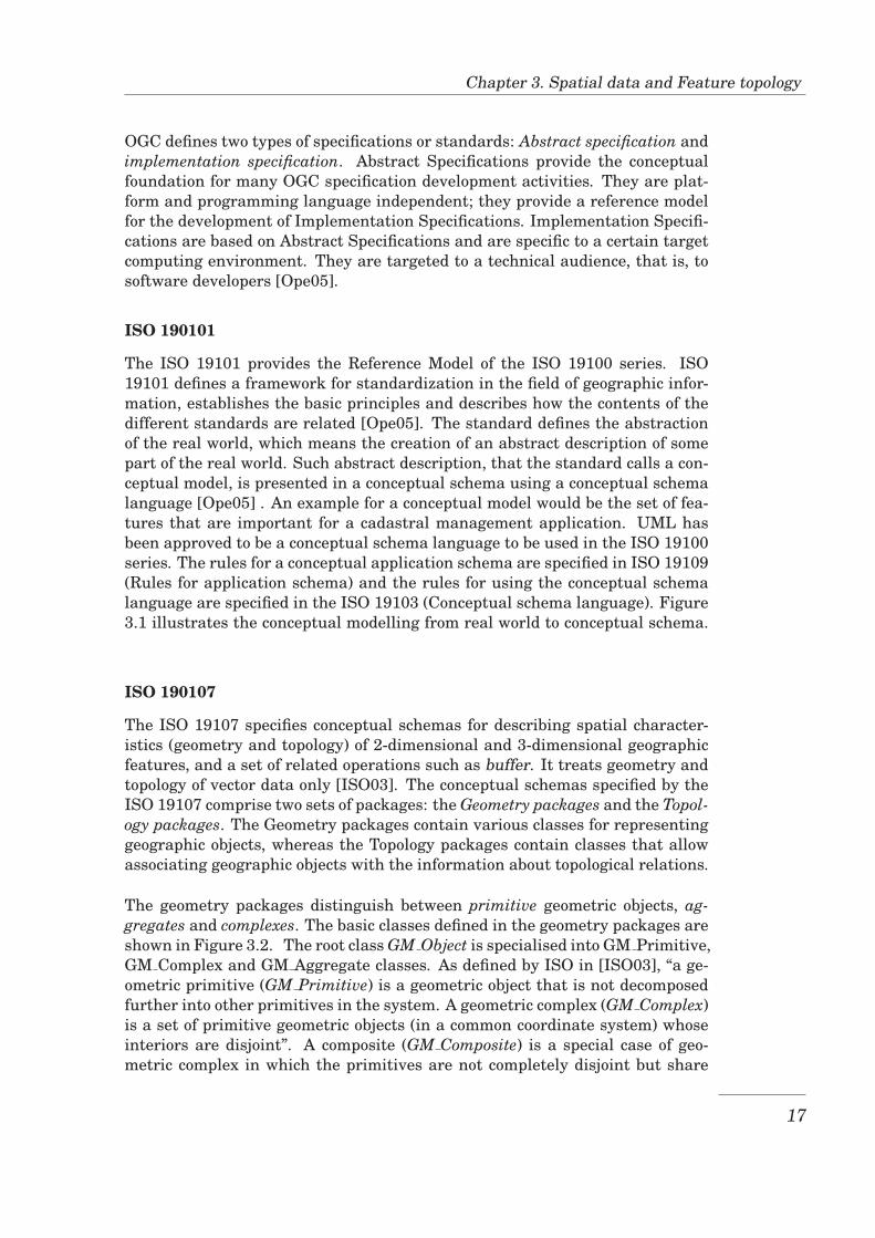
The ISO 19101 provides the Reference Model of the ISO 19100 series. ISO19101 defines a framework for standardization in the field of geographic infor-mation, establishes the basic principles and describes how the contents of thedifferent standards are related [Ope05]. The standard defines the abstractionof the real world, which means the creation of an abstract description of somepart of the real world. Such abstract description, that the standard calls a con-ceptual model, is presented in a conceptual schema using a conceptual schemalanguage [Ope05] . An example for a conceptual model would be the set of fea-tures that are important for a cadastral management application. UML hasbeen approved to be a conceptual schema language to be used in the ISO 19100series. The rules for a conceptual application schema are specified in ISO 19109(Rules for application schema) and the rules for using the conceptual schemalanguage are specified in the ISO 19103 (Conceptual schema language). Figure3.1 illustrates the conceptual modelling from real world to conceptual schema.
ISO 190107
The ISO 19107 specifies conceptual schemas for describing spatial character-istics (geometry and topology) of 2-dimensional and 3-dimensional geographicfeatures, and a set of related operations such as buffer. It treats geometry andtopology of vector data only [ISO03]. The conceptual schemas specified by theISO 19107 comprise two sets of packages: the Geometry packages and the Topol-ogy packages. The Geometry packages contain various classes for representinggeographic objects, whereas the Topology packages contain classes that allowassociating geographic objects with the information about topological relations.
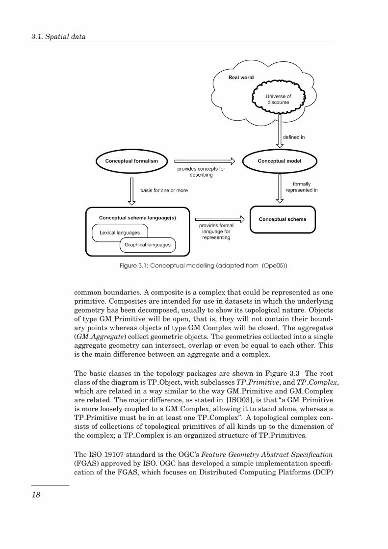
The geometry packages distinguish between primitive geometric objects, ag-gregates and complexes. The basic classes defined in the geometry packages areshown in Figure 3.2. The root class GM Object is specialised into GM Primitive,GM Complex and GM Aggregate classes. As defined by ISO in [ISO03], “a ge-ometric primitive (GM Primitive) is a geometric object that is not decomposedfurther into other primitives in the system. A geometric complex (GM Complex)is a set of primitive geometric objects (in a common coordinate system) whoseinteriors are disjoint”. A composite (GM Composite) is a special case of geo-metric complex in which the primitives are not completely disjoint but share
17
3.1. Spatial data
Figure 3.1: Conceptual modelling (adapted from [Ope05])
common boundaries. A composite is a complex that could be represented as oneprimitive. Composites are intended for use in datasets in which the underlyinggeometry has been decomposed, usually to show its topological nature. Objectsof type GM Primitive will be open, that is, they will not contain their bound-ary points whereas objects of type GM Complex will be closed. The aggregates(GM Aggregate) collect geometric objects. The geometries collected into a singleaggregate geometry can intersect, overlap or even be equal to each other. Thisis the main difference between an aggregate and a complex.
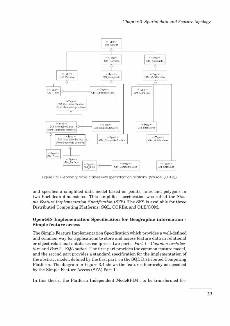
The basic classes in the topology packages are shown in Figure 3.3 The rootclass of the diagram is TP Object, with subclasses TP Primitive, and TP Complex,which are related in a way similar to the way GM Primitive and GM Complexare related. The major difference, as stated in [ISO03], is that “a GM Primitiveis more loosely coupled to a GM Complex, allowing it to stand alone, whereas aTP Primitive must be in at least one TP Complex”. A topological complex con-sists of collections of topological primitives of all kinds up to the dimension ofthe complex; a TP Complex is an organized structure of TP Primitives.
The ISO 19107 standard is the OGC’s Feature Geometry Abstract Specification(FGAS) approved by ISO. OGC has developed a simple implementation specifi-cation of the FGAS, which focuses on Distributed Computing Platforms (DCP)
18
Chapter 3. Spatial data and Feature topology
Figure 3.2: Geometry basic classes with specialization relations. (Source: [ISO03])
and specifies a simplified data model based on points, lines and polygons intwo Euclidean dimensions. This simplified specification was called the Sim-ple Feature Implementation Specification (SFS). The SFS is available for threeDistributed Computing Platforms: SQL, CORBA and OLE/COM.
OpenGIS Implementation Specification for Geographic information -Simple feature access
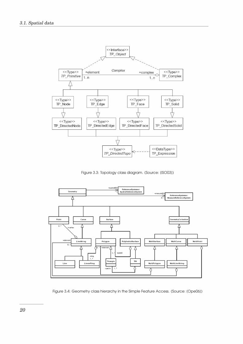
The Simple Feature Implementation Specification which provides a well-definedand common way for applications to store and access feature data in relationalor object-relational databases comprises two parts: Part 1 - Common architec-ture and Part 2 - SQL option. The first part provides the common feature model,and the second part provides a standard specification for the implementation ofthe abstract model, defined by the first part, on the SQL Distributed ComputingPlatform. The diagram in Figure 3.4 shows the features hierarchy as specifiedby the Simple Feature Access (SFA) Part 1.
In this thesis, the Platform Independent Model(PIM), to be transformed fol-
19
3.1. Spatial data
Figure 3.3: Topology class diagram. (Source: [ISO03])
Figure 3.4: Geometry class hierarchy in the Simple Feature Access. (Source: [Ope06])
20
Chapter 3. Spatial data and Feature topology
lowing MDA technique, will be built using the spatial data concepts specifiedby ISO 19107 because the latter is platform independent. The target PlatformSpecific Model(PSM) will be built following the Simple Feature implementationSpecification for SQL because the target platform (PostgreSQL/PostGIS) is anSQL database management system.
3.2 Feature topology
The feature topology describes the structure of space mainly through neigh-bourhood relationships between different topological elements that make thefeatures. Throughout this thesis, the feature topology will be dealt with. To laythe foundation for a better understanding of subsequent chapters, this sectionprovides an overview of feature topology and its current support in DatabaseManagement Systems. Also this section describes different options of realizingthe feature topology.
3.2.1 Overview of the feature topology
When one is interested in single objects, he/she needs to consider the data modeland the representation mode only. Unlikewise, when geographic objects areconsidered together, they present spatial relationships which are of interest aswell. Topological relationships are the most important of these relationships.Topology studies topological relations of features. Topological relations havebeen a subject of intense research (Max [Ege89], Max et al. [EF91], Max etal. [ECF94], Markus et al. [SB06], etc) that has produced a formal definition ofthem and the models for describing and computing them. The primary modelsthat resulted from the research are the 4-Intersection Model, the 9-IntersectionModel and their dimensionally-extended versions.
The 4-Intersection Model (4-IM)
The 4-Intersection model is based on the distinction between the interior (A◦)and the boundary (∂A) of a region A. All possible intersections of the interiorsand the boundaries of two spatial objects A and B form a 4-Intersectin Matrix.By considering whether the value is empty or non-empty, a number of topologi-cal relations can be distinguished. For regions with connected boundaries, eightof those relations can be realized and have led to eight topological predicates(Boolean functions that are used to test the topological relationships betweentwo spatial objects): disjoint, meet, equal, inside, contains, covers, coveredByand overlap. These relations are mutually exclusive.
The 9-Intersection Model (9-IM)
The 4-intersection matrix makes it possible to identify topological relationsbetween simple spatial objects, that is, spatial objects with connected bound-aries [ECF94]. To make it possible to identify relations between regions with
21
3.2. Feature topology
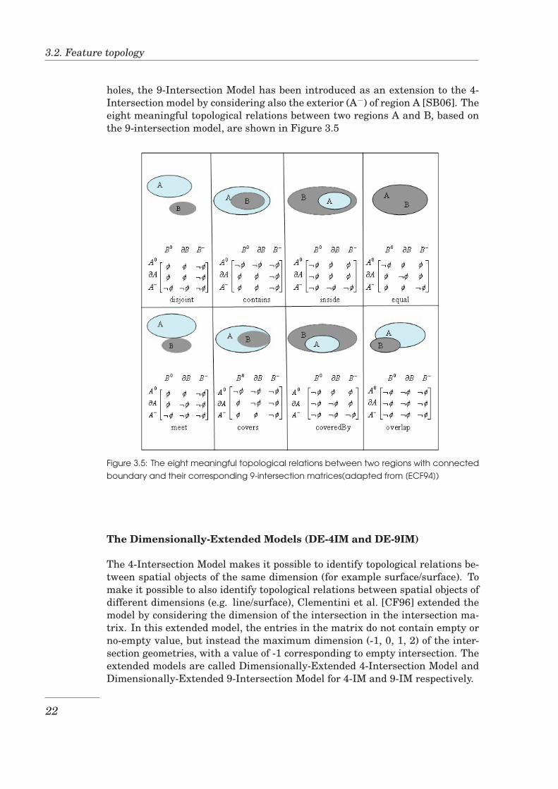
holes, the 9-Intersection Model has been introduced as an extension to the 4-Intersection model by considering also the exterior (A−) of region A [SB06]. Theeight meaningful topological relations between two regions A and B, based onthe 9-intersection model, are shown in Figure 3.5
Figure 3.5: The eight meaningful topological relations between two regions with connectedboundary and their corresponding 9-intersection matrices(adapted from [ECF94])
The Dimensionally-Extended Models (DE-4IM and DE-9IM)
The 4-Intersection Model makes it possible to identify topological relations be-tween spatial objects of the same dimension (for example surface/surface). Tomake it possible to also identify topological relations between spatial objects ofdifferent dimensions (e.g. line/surface), Clementini et al. [CF96] extended themodel by considering the dimension of the intersection in the intersection ma-trix. In this extended model, the entries in the matrix do not contain empty orno-empty value, but instead the maximum dimension (-1, 0, 1, 2) of the inter-section geometries, with a value of -1 corresponding to empty intersection. Theextended models are called Dimensionally-Extended 4-Intersection Model andDimensionally-Extended 9-Intersection Model for 4-IM and 9-IM respectively.
22
Chapter 3. Spatial data and Feature topology
3.2.2 Topology realisation options
Based on the way of expressing topological relationships among component ob-jects of a feature collection, there are three commonly used models of represent-ing feature collections: spaghetti, network and topological models [RSV02].
Spaghetti Model
The spaghetti model is a vector representation of spatial objects where linesand regions are represented as an ordered list of points, a point being a pair ofcoordinates [RSV02]. In this model, no topology information is stored, and alltopological relationships must be computed on demand.
With the notation: [ ] for tuple, 〈〉 for list, and { } for set, the structure for points,polylines, polygons, and regions can be summarised as follows:
point : [x: real, y: real]polyline: 〈point〉polygon: 〈point〉region: { polygon }
Network model
This model was initially designed for representing networks for transportation,utilities, and so on. This model introduces two new types: node and arc (some-times called edge). A node is a distinguished point that connects a list of arcs.An arc is a polyline starting at a node and ending at another node. A node iseither an arc end point or an isolated point in the plane. A point is representedby a pair of coordinates, a node by a tuple containing the point coordinates anda list of arcs originating from it. An arc is represented as a tuple containing itsstarting node, its ending node and a list of intermediate vertices, and a polygonis represented by the ordered list of vertices of its polygon boundaries [RSV02].This representation can be summarised as follows:
point : [x: real, y: real]node: [point, 〈arc〉]arc: [node-start, node-end, 〈point〉]polygon: 〈point〉region: { polygon }
Topological model
The topological model is similar to the network model, except that the networkis planar, which is not necessarily the case for the network model. This pla-narity implies a planar subdivision into adjacent polygons, some of which maynot correspond to actual geographic objects [RSV02]. The representation differsfrom that in the network model on arc and polygon. To represent an arc, theleft and right polygons to the arc are also specified. A polygon is representedby an ordered list of arcs that form its boundaries. The representation in this
23
3.2. Feature topology
model can be summarised as follows:
point : [x: real, y: real]node: [point, 〈arc〉]arc: [node-start, node-end, left-poly, right-poly, 〈point〉]polygon: 〈arc〉region: { polygon }
Evaluation of topology realisation options
Each of the models of realising the feature topology has its pros and cons. Foreach model, some advantages and disadvantages are described in the following.
The spaghetti model has the advantage of being simple to understand and use,and it is easy to add new objects to the collection because all objects are storedindependently. However the spaghetti model has also drawbacks such as rep-resentation redundancy (e.g. a shared boundary is stored twice). This redun-dancy leads to inefficient use of storage capacity when the data sets becomelarge. Furthermore, it carries a risk of inconsistency as the replicated boundaryof two adjacent objects may have slightly different coordinates due to differentsources of information [RSV02]. Also, since no explicit storage of informationon topological relationships, the execution of queries involving topological rela-tionships may be less efficient. The spaghetti model explicitly represents all theentities being modelled. This is an advantage when it is selected as the PSM inthe MDA approach where we need to describe as much as possible the entitiesbeing modelled at both the PIM and PSM, to enable a good mapping of PIM toPSM.
The network model has advantages of supporting efficient line connectivitytests and network computations, such as shortest paths. It is easy to navi-gate through the network, by choosing the arc to follow whenever a node is en-countered [RSV02]. However, since the line connectivity is the only topologicalinformation explicitly stored; without information on topological relationshipsbetween two-dimensional objects (area features), the execution of queries in-volving topological relationships may be less efficient like in spaghetti model.Also the storage of line connectivity makes the model complex to understandand use compared to spaghetti model. The network model describes very welllinear features but it poorly describes area features. Given that this thesis fo-cuses on area features and that this model contains less information on areafeatures, it is not a suitable PSM candidate for a good mapping in the MDAapproach in the context of this project.
The topological model has the advantage that the execution of queries involvingtopological relationships is efficient. Also consistency maintenance and updatesare easier with the topological model than with the spaghetti model; the geome-try of each shared edge is stored once and not twice as in spaghetti model whereupdate propagation needs to be handled. The general disadvantage of this
24
Chapter 3. Spatial data and Feature topology
model is the cost of computing and maintaining the planar graph (computingall the intersections). This makes some operations like map overlay, extremelyexpensive [KS00]. Similarly, the addition of a new object to the collection re-quires the precomputation of part of the planar graph. The complexity of thestructure resulting from this model may slow down some operations [The01].For example, displaying a part of a map requires scanning a set of line seg-ments. Moreover, with topological model, scanning is much slower than withspaghetti model [KS00]. This model does not describe explicitly all entities be-ing modelled but it includes a detailed description of the relationships betweencomponents of those entities which makes it a rich PSM in the MDA approach.
There are many considerations that must be taken during the selection of themodel to use. Some of these considerations are the following:
• The type of data to be stored: for some data, a certain model is more suit-able than others. For example, for roads connectivity data, the networkmodel is the most suitable model.
• The operations that are most likely to be performed on the data. For exam-ple, if the expected queries will never involve topological relationships, thespaghetti model is the most suitable one because it will allow the neededfast data retrieval while avoiding the complex data structure [The01].
• The DBMS to be used: A DBMS may have explicit support for certainmodels and not others. For example, PostgreSQL/PostGIS has no explicitsupport for the network model.
3.2.3 Feature topology support in Database Management Sys-tems
In general, DBMSs support spatial data through an extension to the conven-tional DBMS components. The simplicity of the spaghetti model has made itthe default option in such extension. DBMSs then add support for topologicaldata structure. The support for feature topology in two DBMSs (Oracle andPostgreSQL) is presented in brief in the following.
Feature topology support in Oracle
Oracle DBMS, starting from version 8i, handles spatial data through its ex-tension Oracle Spatial [RSV02]. In addition to the spaghetti model, Oraclesupports also topological and network models. With Oracle Spatial topologymodel you can store information about topological elements and geometry lay-ers, perform certain spatial operations referencing the topological elements, forexample, finding which chains (such as roads) have any topological spatial re-lationship with a specific polygon entity (such as a park). You can also exporttopology data from one database and import it into another database.
25
3.2. Feature topology
The topology data model is built on basic topological elements node, edge andface. A topology geometry (also referred to as a feature) is a spatial represen-tation of a real world object. The geometry is stored in terms of topologicalelements (nodes, edges, and faces). A topology geometry layer is a collectionof topology geometries of a specific type. For example, museums might be thetopology geometry layer that includes the Science museum topology geometrywhich is stored as a node element. In some topologies, the topology geometrylayers have one or more parent-child relationships hence making a topology hi-erarchy. A multilevel hierarchy is also supported. To use the Spatial topologycapabilities, you must first insert data into special edge, node, and face tables,which are created by Spatial when you create a topology. Spatial maintainsa relationship information table for feature tables and topologies associated tothem. Spatial also has the topology data model application programming in-terface (API) that can be used to further manipulate the data structure andperform various operations.
The network data model in Oracle Spatial shares many concepts with the topo-logical data model. The network model is built on the basic elements node andlink (sometimes called edge or segment). The network model contains logical in-formation such as connectivity relationships among nodes and links, directionsof links, and costs of nodes and links. With logical network information, you cananalyze a network and answer questions, many of them related to path comput-ing and tracing. This logical information makes a logical network. In additionalto logical network information, spatial information such as node locations andlink geometries can be associated with the logical network, hence making thespatial network. A spatial network can be directed or undirected, dependingon the application. The network model in Oracle Spatial also supports the net-work hierarchy. The network modelling capabilities of Spatial include schemaobjects and an application programming interface (API). The schema objectsinclude metadata and network tables. The API includes a server-side PL/SQLAPI (the SDO NET package) for creating, managing, and analyzing networksin the database, and a client-side Java API for network analysis. A detaileddiscussion of the topology and network data models can be found in [Mur03].
Feature topology support in PostgreSQL
PostgreSQL DBMS supports spatial data through its extension PostGIS. Post-GIS provides geometry operations and most importantly topological functionsusing the GEOS module [CJE94]. GEOS (Geometry Engine - Open Source)is a C++ version of a part of the Java Topology Suite (JTS), a Java API of 2Dspatial predicates and functions for fundamental geometric operations. Post-greSQL/PostGIS supports the spaghetti model and currently provides the topo-logical model as an option to be enabled. To enable the topological model, youneed a schema-aware PostgreSQL installation (version 7.3 and up), PostGIS-1.1.x, and GEOS-2.1 or up. Enabling the topology creates a separate schemathat will contain the topology-enabling tables and topology-related functions.
26
Chapter 3. Spatial data and Feature topology
Currently, the support for the topology data model in PostGIS is in pre-alphastage [Ref05]. With the topology support enabled you can explicitly store fea-tures’ topology using predefined topological elements (faces, edges and nodes),define geometries composed by those elements and convert these geometries tosimple Geometry objects to make it possible to use all standard functions de-fined on the latter. With the same support, it is also possible to validate thetopology (this is done by retrieving the features that violate the topological re-lationships), and to perform basic topology editing operations .
Our observation on the feature topology support in the DBMSs is that a ma-nipulation of stored spatial data, with interest on topological relationships, re-quires the database designer or user to perform an extensive programming us-ing the provided API. This thesis tries to relieve the database designer/userof this task in some basic operations by taking care of it in the transforma-tional design process. Being the most widely used open source spatial DBMS[RSV02], PostgreSQL/PostGIS has been selected to be used in the implementa-tion phase of this thesis.
27

3.2. Feature topology
28
Chapter 4
Design of area collectionmodelling primitives and thetransformation process
This chapter describes the design of primitives to model collections of area fea-tures. To allow their reusability in different models, these primitives are de-signed using the standard extensibility mechanisms available in UML (stereo-types, tagged values and constraints) which have been described in Section 2.3Furthermore, the primitives are packaged in a UML profile to allow their porta-bility to different projects and modelling tools. This chapter also describes thedesign of the transformation process in which the result at one database designlevel is transformed to another.
4.1 Design of a UML profile for modelling collectionsof area features
An area collection is a spatial object made of one or more related area objects. Itcan be represented by a polygon if it is made of only one element, or by a set ofpolygons (a multipolygon) if it is made of more than one element. The inherentcharacteristic of area collections is that a collection is made of areas that havemutually disjoint interiors. Considering other specific characteristics, we canclassify area collection into a number of categories.
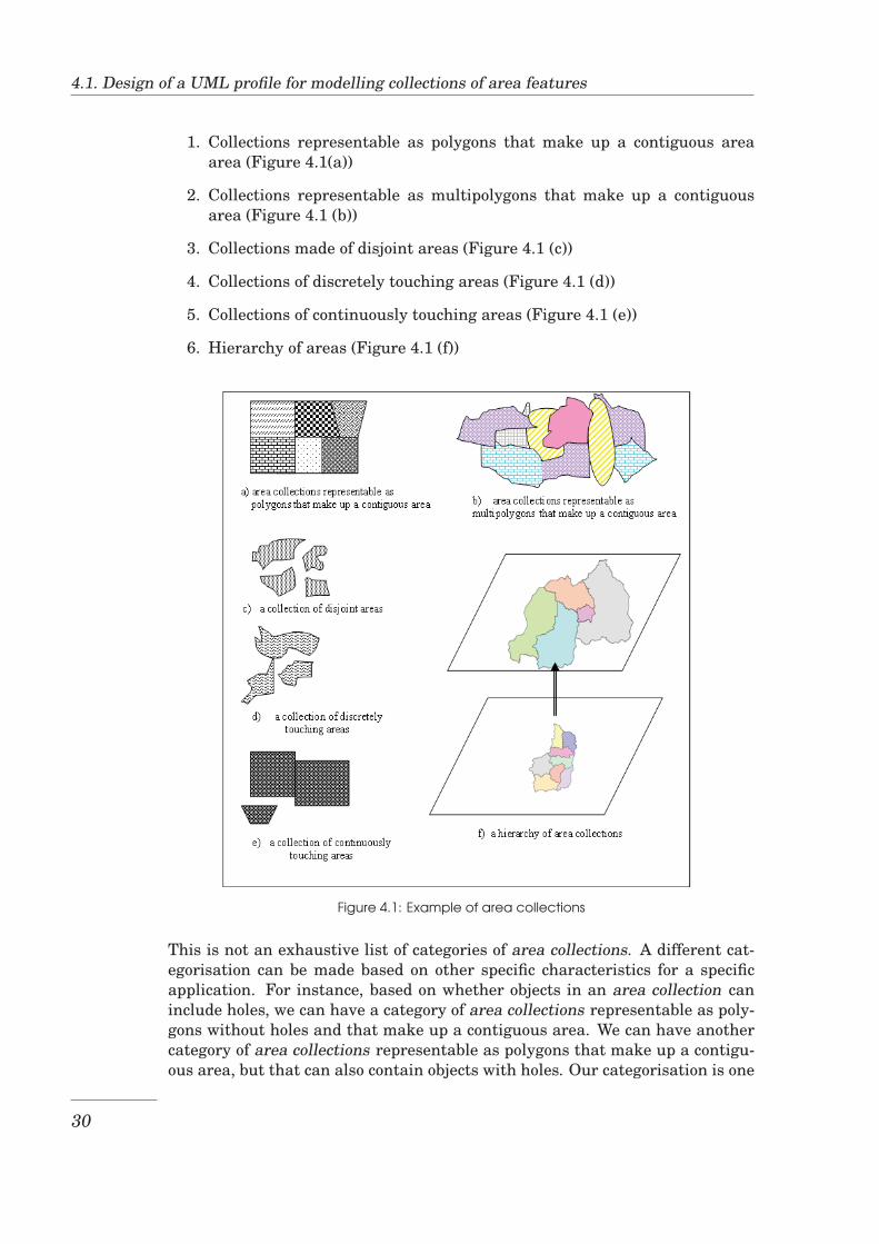
Specific characteristics of area collections are such as whether the objects mak-ing all the related area collections form a contiguous area, whether the ele-ments in one collection are disjoint, touch in points or in line segments andwhether there are area collections with a semantic spatial aggregation connec-tion. A contiguous area is an area in which, from any point in it there existsa path, fully contained in the area, to any other point in the area. A semanticspatial aggregation connection means a relationship in which an object at onelevel is made of the geometric union of some objects at another level. Based onthese characteristics we classify area collections into the following categorieswhich are illustrated in Figure 4.1:
29
4.1. Design of a UML profile for modelling collections of area features
1. Collections representable as polygons that make up a contiguous areaarea (Figure 4.1(a))
2. Collections representable as multipolygons that make up a contiguousarea (Figure 4.1 (b))
3. Collections made of disjoint areas (Figure 4.1 (c))
4. Collections of discretely touching areas (Figure 4.1 (d))
5. Collections of continuously touching areas (Figure 4.1 (e))
6. Hierarchy of areas (Figure 4.1 (f))
Figure 4.1: Example of area collections
This is not an exhaustive list of categories of area collections. A different cat-egorisation can be made based on other specific characteristics for a specificapplication. For instance, based on whether objects in an area collection caninclude holes, we can have a category of area collections representable as poly-gons without holes and that make up a contiguous area. We can have anothercategory of area collections representable as polygons that make up a contigu-ous area, but that can also contain objects with holes. Our categorisation is one
30
Chapter 4. Design of area collection modelling primitives and the transformation process
possible general example that considers mostly encountered real world objectswithout considering the details of a specific application. It is up to the user todecide which modelling primitive most suits the application at hand.
The set of new modelling primitives will be made available as a UML profilecontaining six stereotypes, one for each of the aforementioned categories. Foreach of the six stereotypes, the following can be or are specified: the name of thestereotype that appears in the model, the base class which is the UML meta-model element that serves as the base for the stereotype, a short description ofthe stereotype, an example of a real world object that can be modelled using thisstereotype, an icon providing a distinctive visual clue, constraints that restrictthe real world objects that can be modelled using the stereotype, and a list oftagged values which specify some specific properties that the stereotype carries.Each stereotype is associated with a set of maintenance functions to be used forstoring and manipulating the objects of the type the stereotype represents. Adesign of these functions is presented after the stereotypes.
Stereotypes
1. For collections representable as polygons that make up a contiguous area
Name: ContiguousPolygonalAreaBase class: ClassDescription:
A ContiguousPolygonalArea class is a class of which the instancesrepresent objects representable as polygons that make up a contigu-ous area.
Example:Parcel; parcels form a contiguous area which is the area they occupyand each parcel can be represented by a polygon.
Icon: NoneConstraints:
• Each object can be represented by a polygon• The geometric union of all areas forms a contiguous area• Areas do not overlap
Tagged values: None
2. For collections representable as multipolygons that make up a contiguousarea
Name: ContiguousMultipolygonalAreaBase class: ClassDescription:
A ContiguousMultipolygonalArea class is a class of which the in-stances represent objects representable as multipolygons that makeup a contiguous area.
Example:Land use type; each land use type can be found in one or more sepa-
31
4.1. Design of a UML profile for modelling collections of area features
rate areas and can be represented by a set of polygons. The geometricunion of those land use types form a contiguous area which is the en-tire study area.
Icon: NoneConstraints:
• Each object can be represented by a set of one or more polygons• The geometric union of the representations of all objects forms a
contiguous area• Areas do not overlap
Tagged values: None
3. For a collection made of disjoint areas
Name: DisjointAreaBase class: ClassDescription:
A DisjointArea class is a class of which the instance represents anobject made of one or more areas which are disjoint.
Example:Island country; each island country consists of one or more islandsand any two islands are disjoint.
Icon: NoneConstraints:
• The areas in the collection are mutually disjointTagged values: None
4. For a collection of discretely touching areas
Name: PointTouchAreaBase class: ClassDescription:
A PointTouchArea class is a class of which the instance representsan object made of one or more areas which are disjoint or touch ata finite number of points. A DisjointArea object is a special typeof PointTouchArea object in that its elements are mutually disjoint.Real world objects that share a finite number of points are not com-mon. In general, this class contains erroneous representations of realworld objects, where the errors are due to data acquisition techniquessuch as digitisation.
Example:University (where each university can have many campuses each be-ing considered as one element of the university object); if the cam-puses of any university can not share a boundary, the University is aPointTouchArea class.
Icon: NoneConstraints:
• Any two areas in the collection are disjoint or they touch alongzero-dimensional intersections (points).
32
Chapter 4. Design of area collection modelling primitives and the transformation process
Tagged values: None
5. For a collection of continuously touching areas
Name: LineTouchAreaBase class: ClassDescription:
A LineTouchArea class is a class of which the instance represents anobject made of one or more areas which are disjoint or touch along ei-ther zero-dimensional (points) or one-dimensional (line segments) in-tersections. A DisjointArea object is a special type of LineTouchAreaobject in that its member areas can only be disjoint. Likewise, aPointTouchArea object is a special type of LineTouchArea object inthat its member areas can only be disjoint or share a finite set ofpoints but can not share line segments.
Example:Boarding school; if each boarding school is made of one or two ad-jacent compounds (one for male students and the other for femalestudents), the boarding school is a LineTouchArea class.
Icon: NoneConstraints:
• Any two areas in the collection do not overlap
Tagged values: None
6. For a hierarchy of areas
Name: AreaHierarchyAssociationBase class: AssociationDescription:
An AreaHierarchyAssociation association establishes a semantic spa-tial aggregation connection between area collections such that a col-lection at an upper level equals the geometric union of some collec-tions at a lower level.
Example:An AreaHierarchyAssociation association exists between a State andits Provinces, and also between a province and its Districts.
Icon: NoneConstraints:
• Objects at two associated levels (upper and lower levels) are ofthe same area collection type
• The geometry of any object at the upper level is equal to the geo-metric union of some objects at the lower level
• Each lower level object can be involved in the geometric union tomake only one immediate upper level object.
Tagged values: None
33
4.1. Design of a UML profile for modelling collections of area features
Design of maintenance functions
Database Management Systems (DBMS) that store spatial data have a set offunctions used to store, manipulate and retrieve stored data. However thesefunctions do not perform or perform very limited special treatment of maintain-ing topological dependencies between and within area collections. To enhancethis special treatment of area collections, we design a set of functions that willbe carried by the new modelling primitives.
For ContiguousPolygonalArea and ContiguousMultipolygonalArea objects wepropose the functions to carry out the following operations:
• to add a new ContiguousPolygonalArea object to the set of existing Con-tiguousPolygonalArea objects, or to add a new ContiguousMultipolygo-nalArea object to the set of existing ContiguousMultipolygonalArea ob-jects
• to delete a ContiguousPolygonalArea object or a ContiguousMultipolygo-nalArea object
• to modify a part of the boundary of a ContiguousPolygonalArea or a Con-tiguousMultipolygonalArea object (shrinking or enlarging the object)
• to merge two ContiguousPolygonalArea objects or two ContiguousMulti-polygonalArea objects
Additionally, for ContiguousMultipolygonalArea objects, we propose the func-tions to carry out the following operations:
• to modify an existing ContiguousMultipolygonalArea object adding to it anew component area
• to modify an existing ContiguousMultipolygonalArea object deleting onecomponent area
• to change the membership of a component area from one ContiguousMul-tipolygonalArea object to another
AddToContiguousArea( )
Description:AddToContiguousArea adds a new ContiguousPolygonalArea object to theset of existing ContiguousPolygonalArea objects, or a new Contiguous-MultipolygonalArea object to the set of existing ContiguousMultipolygo-nalArea objects, preserving topological dependencies between the objects.
Input:the name of the table that will contain the objects, an array of names ofnon geometry columns into which values are to be inserted, an array ofvalues to insert into non geometry columns and the geometry value of theobject to be added.
34
Chapter 4. Design of area collection modelling primitives and the transformation process
Output: the text Success if the operation was successful or the cause of failureotherwise.
Algorithm:AddToContiguousArea (T: text, u: text[] v: text[], w: geometry): text
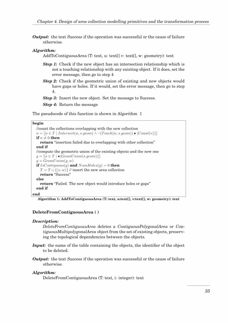
Step 1: Check if the new object has an intersection relationship which isnot a touching relationship with any existing object. If it does, set theerror message, then go to step 4
Step 2: Check if the geometric union of existing and new objects wouldhave gaps or holes. If it would, set the error message, then go to step4.
Step 3: Insert the new object. Set the message to Success.Step 4: Return the message
The pseudocode of this function is shown in Algorithm 1
begin//count the collections overlapping with the new collectionn = [[s ∈ T | Intersect(w, s.geom) ∧ ¬(Touch(w, s.geom)) • 〈Count(∗)〉]]if n �= 0 then
return “insertion failed due to overlapping with other collection”end if//compute the geometric union of the existing objects and the new oneg = [[s ∈ T | •〈GeomUnion(s.geom)〉]]g = GeomUnion(g, w)if IsContiguous(g) and NumHoles(g) = 0 then
T = T ∪ {〈v, w〉} // insert the new area collectionreturn “Success”
elsereturn “Failed. The new object would introduce holes or gaps”
end ifend
Algorithm 1: AddToContiguousArea (T: text, u:text[], v:text[], w: geometry): text
DeleteFromContiguousArea ( )
Description:DeleteFromContiguousArea deletes a ContiguousPolygonalArea or Con-tiguousMultipolygonalArea object from the set of existing objects, preserv-ing the topological dependencies between the objects.
Input: the name of the table containing the objects, the identifier of the objectto be deleted.
Output: the text Success if the operation was successful or the cause of failureotherwise.
Algorithm:DeleteFromContiguousArea (T: text, i: integer): text
35
4.1. Design of a UML profile for modelling collections of area features
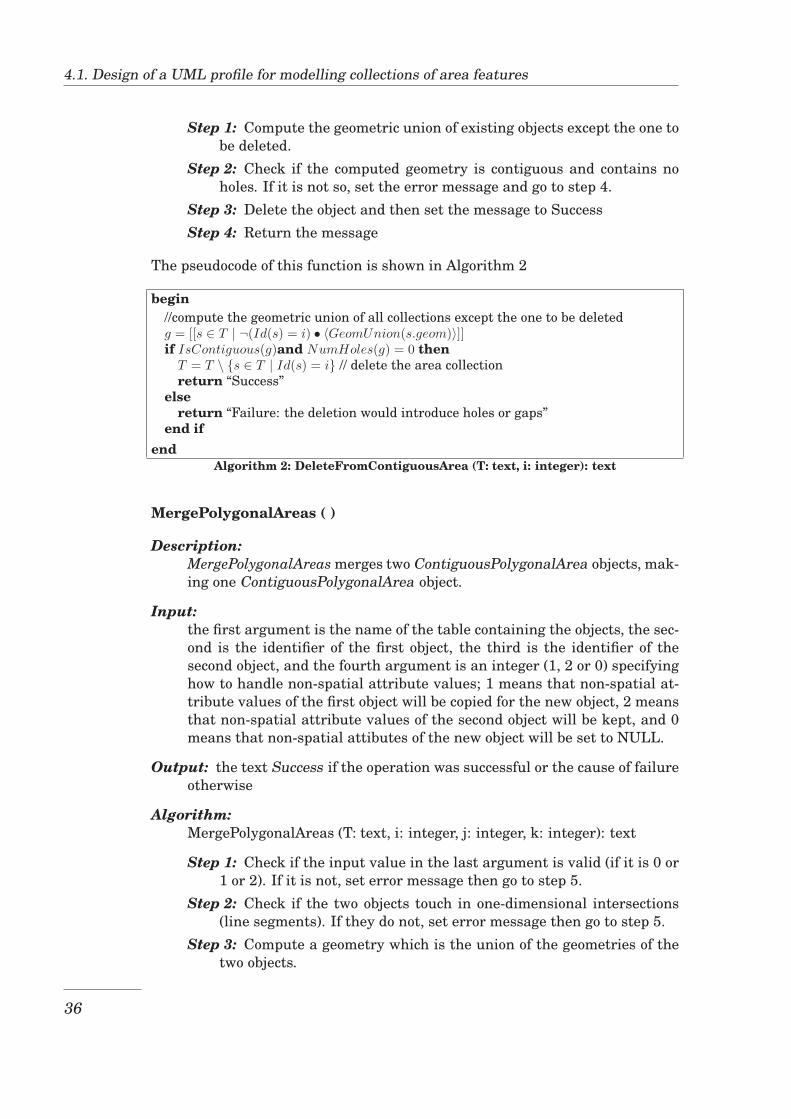
Step 1: Compute the geometric union of existing objects except the one tobe deleted.
Step 2: Check if the computed geometry is contiguous and contains noholes. If it is not so, set the error message and go to step 4.
Step 3: Delete the object and then set the message to SuccessStep 4: Return the message
The pseudocode of this function is shown in Algorithm 2
begin//compute the geometric union of all collections except the one to be deletedg = [[s ∈ T | ¬(Id(s) = i) • 〈GeomUnion(s.geom)〉]]if IsContiguous(g)and NumHoles(g) = 0 then
T = T \ {s ∈ T | Id(s) = i} // delete the area collectionreturn “Success”
elsereturn “Failure: the deletion would introduce holes or gaps”
end ifend
Algorithm 2: DeleteFromContiguousArea (T: text, i: integer): text
MergePolygonalAreas ( )
Description:MergePolygonalAreas merges two ContiguousPolygonalArea objects, mak-ing one ContiguousPolygonalArea object.
Input:the first argument is the name of the table containing the objects, the sec-ond is the identifier of the first object, the third is the identifier of thesecond object, and the fourth argument is an integer (1, 2 or 0) specifyinghow to handle non-spatial attribute values; 1 means that non-spatial at-tribute values of the first object will be copied for the new object, 2 meansthat non-spatial attribute values of the second object will be kept, and 0means that non-spatial attibutes of the new object will be set to NULL.
Output: the text Success if the operation was successful or the cause of failureotherwise
Algorithm:MergePolygonalAreas (T: text, i: integer, j: integer, k: integer): text
Step 1: Check if the input value in the last argument is valid (if it is 0 or1 or 2). If it is not, set error message then go to step 5.
Step 2: Check if the two objects touch in one-dimensional intersections(line segments). If they do not, set error message then go to step 5.
Step 3: Compute a geometry which is the union of the geometries of thetwo objects.
36
Chapter 4. Design of area collection modelling primitives and the transformation process
Step 4: Check the value of the last argument. If it is 1, update the geom-etry of the first object by setting it to the geometry computed in step2, and then delete the second object. If it is 2, update the geometryof the second object by setting it to the geometry computed in step 2,and then delete the first object. If it is 0, insert a new object settingthe value of its geometry attribute to the geometry computed in step2 and thematic attributes to NULL value, and then delete the twoinput objects. Set the message to Success
Step 5: Return the message
The pseudocode of this function is shown in Algorithm 3
MergeMultipolygonalAreas ( )
Description:MergeMultipolygonalAreas takes two ContiguousMultipolygonalArea ob-jects and merges them making one ContiguousMultipolygonalArea object.
Input:the first argument is the name of the table containing the objects , thesecond is the identifier of the first object, the third is the identifier of thesecond object, and the fourth argument is an integer (1, 2 or 0) specifyinghow to handle non-spatial attribute values; 1 means that non-spatial at-tribute values of the first object will be copied for the new object, 2 meansthat non-spatial attribute values of the second object will be kept, and 0means that non-spatial attributes of the new object will be set to NULL.
Output: the text Success if the operation was successful or the cause of failureotherwise
Algorithm:MergeMultipolygonalAreas (T: text, i: integer, j: integer, k: integer): text
Step 1: Check if the input value in the last argument is valid (if it is 0 or1 or 2). If it is not, set the error message and go to step 4.
Step 2: Compute a geometry which is the union of the geometries of thetwo objects.
Step 3: Check the value of the last argument. If it is 1, update the geom-etry of the first object by setting it to the geometry computed in step2, and then delete the second object. If it is 2, update the geometryof the second object by setting it to the geometry computed in step 2,and then delete the first object. If it is 0, insert a new object settingthe value of its geometry attribute to the geometry computed in step2 and thematic attributes to NULL value, and then delete the twoinput objects. Set the message to Success
Step 4: Return the message
The pseudocode of this function is shown in Algorithm 4
37
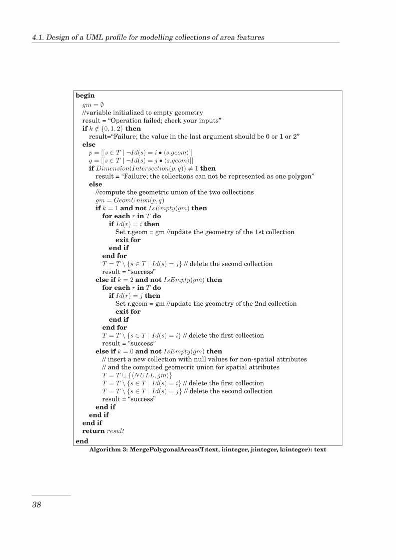
4.1. Design of a UML profile for modelling collections of area features
begingm = ∅//variable initialized to empty geometryresult = “Operation failed; check your inputs”if k /∈ {0, 1, 2} then
result=“Failure; the value in the last argument should be 0 or 1 or 2”else
p = [[s ∈ T | ¬Id(s) = i • 〈s.geom〉]]q = [[s ∈ T | ¬Id(s) = j • 〈s.geom〉]]if Dimension(Intersection(p, q)) �= 1 then
result = “Failure; the collections can not be represented as one polygon”else
//compute the geometric union of the two collectionsgm = GeomUnion(p, q)if k = 1 and not IsEmpty(gm) then
for each r in T doif Id(r) = i then
Set r.geom = gm //update the geometry of the 1st collectionexit for
end ifend forT = T \ {s ∈ T | Id(s) = j} // delete the second collectionresult = “success”
else if k = 2 and not IsEmpty(gm) thenfor each r in T do
if Id(r) = j thenSet r.geom = gm //update the geometry of the 2nd collectionexit for
end ifend forT = T \ {s ∈ T | Id(s) = i} // delete the first collectionresult = “success”
else if k = 0 and not IsEmpty(gm) then// insert a new collection with null values for non-spatial attributes// and the computed geometric union for spatial attributesT = T ∪ {〈NULL, gm〉}T = T \ {s ∈ T | Id(s) = i} // delete the first collectionT = T \ {s ∈ T | Id(s) = j} // delete the second collectionresult = “success”
end ifend if
end ifreturn result
endAlgorithm 3: MergePolygonalAreas(T:text, i:integer, j:integer, k:integer): text
38
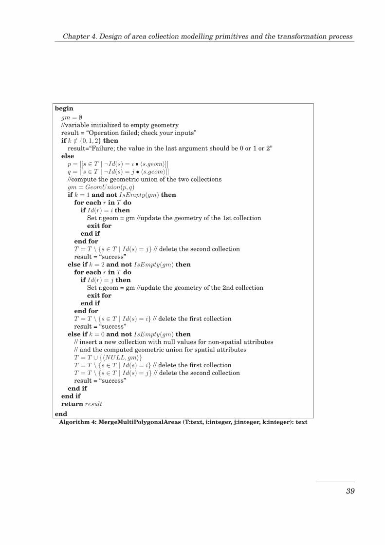
Chapter 4. Design of area collection modelling primitives and the transformation process
begingm = ∅//variable initialized to empty geometryresult = “Operation failed; check your inputs”if k /∈ {0, 1, 2} then
result=“Failure; the value in the last argument should be 0 or 1 or 2”else
p = [[s ∈ T | ¬Id(s) = i • 〈s.geom〉]]q = [[s ∈ T | ¬Id(s) = j • 〈s.geom〉]]//compute the geometric union of the two collectionsgm = GeomUnion(p, q)if k = 1 and not IsEmpty(gm) then
for each r in T doif Id(r) = i then
Set r.geom = gm //update the geometry of the 1st collectionexit for
end ifend forT = T \ {s ∈ T | Id(s) = j} // delete the second collectionresult = “success”
else if k = 2 and not IsEmpty(gm) thenfor each r in T do
if Id(r) = j thenSet r.geom = gm //update the geometry of the 2nd collectionexit for
end ifend forT = T \ {s ∈ T | Id(s) = i} // delete the first collectionresult = “success”
else if k = 0 and not IsEmpty(gm) then// insert a new collection with null values for non-spatial attributes// and the computed geometric union for spatial attributesT = T ∪ {〈NULL, gm〉}T = T \ {s ∈ T | Id(s) = i} // delete the first collectionT = T \ {s ∈ T | Id(s) = j} // delete the second collectionresult = “success”
end ifend ifreturn result
endAlgorithm 4: MergeMultiPolygonalAreas (T:text, i:integer, j:integer, k:integer): text
39
4.1. Design of a UML profile for modelling collections of area features
AddPolygonToMultiArea( )
Description: AddPolygonToMultiArea modifies an existing ContiguousMulti-polygonalArea object by adding one polygon to its member polygons, pre-serving the topological dependencies within that object and between ex-isting ContiguousMultipolygonalArea objects.
Input:the name of the table containing the object, an integer value which isthe identifier of the object to which the polygon is to be added and thegeometry value of the polygon to be added.
Output:the text Success if the operation was successful or the cause of failureotherwise
Algorithm:AddPolygonToMultiArea (T: text, i: integer, g: geometry): text
Step 1: Check if the new polygon has an intersection relationship whichis not a touching relationship with any existing objects. If it does, setthe error message, then go to step 4
Step 2: Check if the geometric union of the existing objects and the newpolygon would have gaps or holes. If it would, set error message, thengo to step 4.
Step 3: Add the new polygon to the object. It is done by updating the ge-ometry of the object of which the id was input, setting it to the unionof this geometry and the new polygon. Set the message to Success.
Step 4: Return the message
The pseudocode of this function is shown in Algorithm 5
DeletePolygonFromMultiArea( )
Description:DeletePolygonFromMultiArea deletes a polygon from an existing Contigu-ousMultipolygonalArea object, preserving the topological dependencieswithin that object and between existing ContiguousMultipolygonalAreaobjects.
Input:the name of the table containing the object, an integer value which is theidentifier of the object containing the polygon to be deleted, the polygonnumber of the polygon to be deleted
Output:the text Success if the operation was successful or the cause of failureotherwise.
40
Chapter 4. Design of area collection modelling primitives and the transformation process
Algorithm:DeletePolygonFromMultiArea (T: text, i: integer, num: integer): text
Step 1: Compute the geometry difference between the geometric union ofall existing objects and the polygon to be deleted (polygon of whichthe polygon number was input).
Step 2: Check if the computed geometry is a contiguous area withoutholes. If it is not, set the error message, then go to step 4.
Step 3: Delete the polygon of which the polygon number was input. Thisis done by updating the geometry of the object, setting it to the dif-ference between this geometry and the polygon to be deleted. Set themessage to Success.
Step 4: Return the message
The pseudocode of this function is shown in Algorithm 6
ReassignCollection( )
Description:ReassignCollection changes the membership of a polygon from one Con-tiguousMultipolygonalArea object to another, preserving topological de-pendencies between existing ContiguousMultipolygonalArea objects.
Input:four arguments; the name of the table containing the two objects, an in-teger which is the identifier of the source object, an integer which is theidentifier of the destination object, and the polygon number of the polygonfor which membership is to be changed.
Output:the text Success if the operation was successful or the cause of failureotherwise.
Algorithm:ReassignCollection( T: text, src: integer, dest: integer, num: integer ): text
Step 1: Update the geometry of the source object by setting it to the differ-ence between the current geometry value and the polygon concerned.
Step 2: Update the geometry of the destination object by setting it to thegeometric union of the current geometry value and the polygon forwhich membership is to be changed. Set the message to Success.
Step 3: Return the message
The pseudocode of this function is shown in Algorithm 7
41
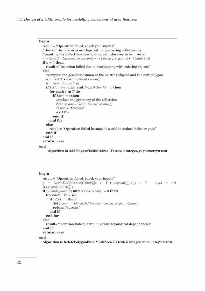
4.1. Design of a UML profile for modelling collections of area features
beginresult = “Operation failed; check your inputs”//check if the new area overlaps with any existing collection by//counting the collections overlapping with the area to be insertedn = [[s ∈ T | Intersect(g, s.geom) ∧ ¬(Touch(g, s.geom)) • 〈Count(∗)〉]]if n �= 0 then
result = “insertion failed due to overlapping with existing objects”else
//compute the geometric union of the existing objects and the new polygonh = [[s ∈ T • 〈GeomUnion(s.geom)〉]]h = GeomUnion(h, g)if IsContiguous(h) and NumHoles(h) = 0 then
for each r in T doif Id(r) = i then
//update the geometry of the collectionSet r.geom = GeomUnion(r.geom, g)result = “Success”exit for
end ifend for
elseresult = “Operation failed because it would introduce holes or gaps”
end ifend ifreturn result
endAlgorithm 5: AddPolygonToMultiArea (T: text, i: integer, g: geometry): text
beginresult = “Operation failed; check your inputs”g = GeomDifference(Union([[s ∈ T • 〈s.geom〉]]), ([[s ∈ T | s.gid = i •〈(s.geom)(num)〉]]))if IsContiguous(h) and NumHoles(h) = 0 then
for each r in T doif Id(r) = i then
Set r.geom = GeomDifference(r.geom, (r.geom)(num))return “success”
end ifend for
elseresult=“operation failed; it would violate topological dependencies”
end ifreturn result
endAlgorithm 6: DeletePolygonFromMultiArea (T: text, i: integer, num: integer): text
42
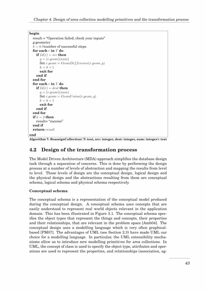
Chapter 4. Design of area collection modelling primitives and the transformation process
beginresult = “Operation failed; check your inputs”g:geometryk = 0 //number of successful stepsfor each r in T do
if Id(r) = src theng = (r.geom)(num)Set r.geom = GeomDifference(r.geom, g)k = k + 1exit for
end ifend forfor each r in T do
if Id(r) = dest theng = (r.geom)(num)Set r.geom = GeomUnion(r.geom, g)k = k + 1exit for
end ifend forif k = 2 then
result= “success”end ifreturn result
endAlgorithm 7: ReassignCollection( T: text, src: integer, dest: integer, num: integer): text
4.2 Design of the transformation process
The Model Driven Architecture (MDA) approach simplifies the database designtask through a separation of concerns. This is done by performing the designprocess at a number of levels of abstraction and mapping the results from levelto level. Those levels of design are the conceptual design, logical design andthe physical design and the abstractions resulting from them are conceptualschema, logical schema and physical schema respectively.
Conceptual schema
The conceptual schema is a representation of the conceptual model producedduring the conceptual design. A conceptual schema uses concepts that areeasily understood to represent real world objects relevant in the applicationdomain. This has been illustrated in Figure 3.1. The conceptual schema spec-ifies the object types that represent the things and concepts, their propertiesand their relationships, that are relevant in the problem space [Amb04]. Theconceptual design uses a modelling language which is very often graphical-based [PM07]. The advantages of UML (see Section 2.3) have made UML ourchoice for a modelling language. In particular, the UML extensibility mecha-nisms allow us to introduce new modelling primitives for area collections. InUML, the concept of class is used to specify the object type, attributes and oper-ations are used to represent the properties, and relationships (association, ag-
43
4.2. Design of the transformation process
gregation, composition and inheritance) are used to represent the relationshipsbetween objects. A detailed discussion of these object-oriented concepts can befound in [Amb04]. The conceptual schema will be built using the modellingprimitives provided by the modelling language and the additional modellingprimitives developed using UML extensibility mechanisms.
Logical schema
While the conceptual design concentrates on specifying the data contents ofa database, the logical design specifies the logical structure of the data in thedatabase. That is, it specifies the structure of the data that a specific DBMS willpresent to the user. A logical schema represents real world objects, their prop-erties and relationships using the concepts of tables, attributes (or columns),primary keys, foreign keys, etc., as they are available in the DBMS being used.These concepts form the relational data model, named so because the basic unitin this data model is the ’table’ (also referred to as a relation). A detailed dis-cussion of the relational data model concepts can be found in [EN07].
Physical schema
The physical design specifies the schema, obtained from logical design, in theSQL of the DBMS chosen for implementation. In addition to this, the physi-cal design fine-tunes the logical schema to make efficient use of the physicalstorage space and enhance the performance of the database according to therequirements of the application [MVC03]. The concepts of indexes are used atthis level of design. In this research, the physical design activities will be lim-ited to expressing the database schema in the SQL of the target DBMS and aperformance consideration limited to SQL statements to create indexes.
Considerations related to spatial data
The description of the schema levels given above is general for the design of anydatabase. Since this research deals with spatial databases, it further considerssome spatial data peculiarities described in chapter 3. These are for instancespatial data types and spatial topological relationships. During the conceptualdesign, area collections will be modelled using the modelling primitives thathave been presented in Section 4.1. Spatial indexes will be considered to fine-tune the logical schema for better database performance.
The transformation process
The major advantage of MDA is the ability to transform one type of modelinto another type, and this being done with a certain level of automation. Inthe context of MDA, the conceptual schema is a Platform Independent Model(PIM) whereas the logical and physical schemas are Platform Specific Models(PSM). Therefore the MDA approach allows the transformation from conceptualschema to logical schema and from logical schema to physical schema withoutexcluding the transformation at the same schema level. However the transfor-mation from conceptual schema to logical schema is the most challenging due
44
Chapter 4. Design of area collection modelling primitives and the transformation process
to the “impedance mismatch” between the two schema levels [Amb04]. The twoschemas are based on different paradigms (the object-oriented paradigm andthe relational paradigm respectively) leading to mismatch such as concept inone schema missing a corresponding concept in the other schema. For exam-ple, the inheritance relationship available in conceptual schemas has no directcorresponding concept in logical schemas for most of DMBSs. The diagram inFigure 4.2 illustrates the transformational database design process of whichthe transformation process is a part.
The transformation from conceptual schema to logical schema and the transfor-mation from logical schema to physical schema are described in the following.
From conceptual schema to logical schema
The transformation from conceptual schema to logical schema takes as inputa UML class diagram, which is the conceptual model of the database, andproduces as output another UML class diagram that represents the relationalmodel of the database. The transformation is done following a set of MDA trans-formation rules. Since the logical schema is a PSM, the MDA transformationrules are influenced by the implementation choice. General MDA transforma-tion rules are listed below. Customisations of those rules for handling spatialdata concepts are mentionned also. A detailed description of these customisa-tions will be presented in a section on the implementation of the transformationprocess where implementation choices are considered.
1. Transform each class to one table: in the simplest case each class is trans-formed to one table. However some situations require further decision;if classes are linked by an inheritance relationship, you need to select aninheritance strategy. There are three basic ways to translate classes andtheir inheritance relationship:
• For each class hierarchy, create a single corresponding table that con-tains all the attributes in all classes in the hierarchy. This table istherefore the union of every class in the hierarchy. For example, aclass hierarchy made of Member, Teacher, Student and Secretary canbe transformed in this way to produce only one table.
• For each class hierarchy branch, create only one table that will in-clude as columns all the attributes within that branch (including in-herited attributes). In this case the parent class will have no corre-sponding table. For example, if Teacher inherits Member only, thenthe table will contain attributes of Member and those of Teacher only.
• For each class in the hierarchy, create one corresponding table con-taining only the attributes of that class.
An area collection class is transformed into one table in the spaghettimodel, but it is transformed into four tables and one type class in thetopological model. This transformation will be described in a section onthe implementation of the transformation process.
45
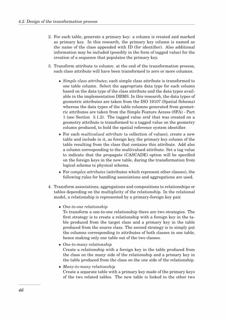
4.2. Design of the transformation process
2. For each table, generate a primary key: a column is created and markedas primary key. In this research, the primary key column is named asthe name of the class appended with ID (for identifier). Also additionalinformation may be included (possibly in the form of tagged value) for thecreation of a sequence that populates the primary key.
3. Transform attribute to column: at the end of the transformation process,each class attribute will have been transformed to zero or more columns.
• Simple class attributes; each simple class attribute is transformed toone table column. Select the appropriate data type for each columnbased on the data type of the class attribute and the data types avail-able in the implementation DBMS. In this research, the data types ofgeometric attributes are taken from the ISO 19107 (Spatial Schema)whereas the data types of the table columns generated from geomet-ric attributes are taken from the Simple Feature Access (SFA) - Part1 (see Section 3.1.2). The tagged value srid that was created on ageometry attribute is transformed to a tagged value on the geometrycolumn produced, to hold the spatial reference system identifier.
• For each multivalued attribute (a collection of values), create a newtable and include in it, as foreign key, the primary key column of thetable resulting from the class that contains this attribute. Add alsoa column corresponding to the multivalued attribute. Set a tag valueto indicate that the propagate (CASCADE) option will be specifiedon the foreign keys in the new table, during the transformation fromlogical schema to physical schema.
• For complex attributes (attributes which represent other classes), thefollowing rules for handling associations and aggregations are used.
4. Transform associations, aggregations and compositions to relationships ortables depending on the multiplicity of the relationship. In the relationalmodel, a relationship is represented by a primary-foreign key pair.
• One-to-one relationshipTo transform a one-to-one relationship there are two strategies. Thefirst strategy is to create a relationship with a foreign key in the ta-ble produced from the target class and a primary key in the tableproduced from the source class. The second strategy is to simply putthe columns corresponding to attributes of both classes in one table,hence making only one table out of the two classes.
• One-to-many relationshipCreate a relationship with a foreign key in the table produced fromthe class on the many side of the relationship and a primary key inthe table produced from the class on the one side of the relationship.
• Many-to-many relationshipCreate a separate table with a primary key made of the primary keysof the two related tables. The new table is linked to the other two
46
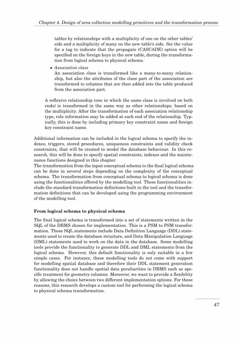
Chapter 4. Design of area collection modelling primitives and the transformation process
tables by relationships with a multiplicity of one on the other tables’side and a multiplicity of many on the new table’s side. Set the valuefor a tag to indicate that the propagate (CASCADE) option will bespecified on the foreign keys in the new table, during the transforma-tion from logical schema to physical schema.
• Association classAn association class is transformed like a many-to-many relation-ship, but also the attributes of the class part of the association aretransformed to columns that are then added into the table producedfrom the association part.
A reflexive relationship (one in which the same class is involved on bothends) is transformed in the same way as other relationships; based onthe multiplicity. After the transformation of each association relationshiptype, role information may be added at each end of the relationship. Typ-ically, this is done by including primary key constraint name and foreignkey constraint name.
Additional information can be included in the logical schema to specify the in-dexes, triggers, stored procedures, uniqueness constraints and validity checkconstraints, that will be created to model the database behaviour. In this re-search, this will be done to specify spatial constraints, indexes and the mainte-nance functions designed in this chapter.The transformation from the input conceptual schema to the final logical schemacan be done in several steps depending on the complexity of the conceptualschema. The transformation from conceptual schema to logical schema is doneusing the functionalities offered by the modelling tool. These functionalities in-clude the standard transformation definitions built in the tool and the transfor-mation definitions that can be developed using the programming environmentof the modelling tool.
From logical schema to physical schema
The final logical schema is transformed into a set of statements written in theSQL of the DBMS chosen for implementation. This is a PSM to PSM transfor-mation. These SQL statements include Data Definition Language (DDL) state-ments used to create the database structure, and Data Manipulation Language(DML) statements used to work on the data in the database. Some modellingtools provide the functionality to generate DDL and DML statements from thelogical schema. However, this default functionality is only suitable in a fewsimple cases. For instance, these modelling tools do not come with supportfor modelling spatial database and therefore their DDL statement generationfunctionality does not handle spatial data peculiarities in DBMS such as spe-cific treatment for geometry columns. Moreover, we want to provide a flexibilityby allowing the choice between two different implementation options. For thesereasons, this research develops a custom tool for performing the logical schemato physical schema transformation.
47
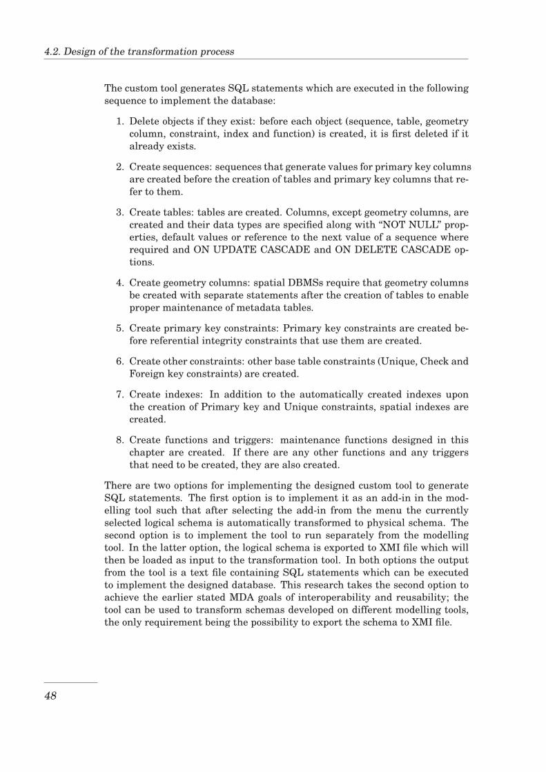
4.2. Design of the transformation process
The custom tool generates SQL statements which are executed in the followingsequence to implement the database:
1. Delete objects if they exist: before each object (sequence, table, geometrycolumn, constraint, index and function) is created, it is first deleted if italready exists.
2. Create sequences: sequences that generate values for primary key columnsare created before the creation of tables and primary key columns that re-fer to them.
3. Create tables: tables are created. Columns, except geometry columns, arecreated and their data types are specified along with “NOT NULL” prop-erties, default values or reference to the next value of a sequence whererequired and ON UPDATE CASCADE and ON DELETE CASCADE op-tions.
4. Create geometry columns: spatial DBMSs require that geometry columnsbe created with separate statements after the creation of tables to enableproper maintenance of metadata tables.
5. Create primary key constraints: Primary key constraints are created be-fore referential integrity constraints that use them are created.
6. Create other constraints: other base table constraints (Unique, Check andForeign key constraints) are created.
7. Create indexes: In addition to the automatically created indexes uponthe creation of Primary key and Unique constraints, spatial indexes arecreated.
8. Create functions and triggers: maintenance functions designed in thischapter are created. If there are any other functions and any triggersthat need to be created, they are also created.
There are two options for implementing the designed custom tool to generateSQL statements. The first option is to implement it as an add-in in the mod-elling tool such that after selecting the add-in from the menu the currentlyselected logical schema is automatically transformed to physical schema. Thesecond option is to implement the tool to run separately from the modellingtool. In the latter option, the logical schema is exported to XMI file which willthen be loaded as input to the transformation tool. In both options the outputfrom the tool is a text file containing SQL statements which can be executedto implement the designed database. This research takes the second option toachieve the earlier stated MDA goals of interoperability and reusability; thetool can be used to transform schemas developed on different modelling tools,the only requirement being the possibility to export the schema to XMI file.
48
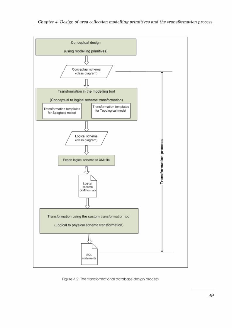
Chapter 4. Design of area collection modelling primitives and the transformation process
Figure 4.2: The transformational database design process
49

4.2. Design of the transformation process
50
Chapter 5
Implementation of modellingprimitives and thetransformation process
This chapter presents the implementation of area collections modelling prim-itives and the transformation process. Section 5.1 presents the implementa-tion tools, Section 5.2 presents the implementation of the primitives while Sec-tion 5.3 presents the implementation of the transformation process. Section5.4 summarises the steps taken to perform the whole transformational design.Finally, Section 5.5 presents the testing that has been done to validate the mod-elling primitives and the transformation process developed.
5.1 Implementation tools
The implementation of the primitives for modelling area collections requires aUML-based implementation tool with Model Driven Architecture (MDA) sup-port. Among the widely used such tools there are: Enterprise Architect de-veloped by Sparx Systems [Spa], and Rational Rose developed by IBM [IBMa].Enterprise Architect being one of the widely used tools with support for XMLMetadata Interchange (XMI) that is needed in the implementation of the trans-formation process, it has been chosen for creating the new modelling primitives.
Our choice for the implementation of the transformation process involves usingthe capabilities provided by the modelling tool and the development of a customtool to carry out some steps of the transformation. Software resources used inthis implementation are:
1. Enterprise Architect 7.1Enterprise Architect is used as the modelling tool.
2. Java Software Development Kit 1.6 (JDK 1.6)Java is used to develop our custom transformation tool. It has been se-lected for its wide support for XML parsing that is involved in the trans-
51
5.2. Implementation of primitives for modelling area collections
formation, and for our convenience. However a different programminglanguage with XML parsing support can be used.
3. PostgreSQL/PostGIS (PostgreSQL 8.3 and PostGIS 1.3.3)PostgreSQL/PostGIS is our target Database Management System (DBMS)for the implementation of a designed database. It has been selected be-cause it is the most widely used Open Source Spatial DBMS and becauseof its topological model that we want to test and improve.
4. SQuirreL SQL ClientThis tool is used to interact with PostgreSQL/PostGIS throughout the im-plementation and testing phases.
5. Quantum GIS (QGIS 0.11.0 Metis)QGIS is used for spatial data visualization that is needed during the im-plementation and testing phases.
5.2 Implementation of primitives for modelling areacollections
The area collections modelling primitives that have been presented in Sec-tion 4.1 are created in Enterprise Architect. As shown in Figure 5.1, five mod-elling primitives; ContiguousPolygonalArea, ContiguousMultiPolygonalArea, Dis-jointArea, PointTouchArea and LineTouchArea extend the standard Class mod-elling primitive, while the AreaHierarchyAssociation extends the standard As-sociation modelling primitive. These modelling primitives are packaged in aUML profile that is then made available as an XML file that a user can importinto his/her Enterprise Architect project.
The functions associated with these modelling primitives are implemented us-ing the procedural language of PostgreSQL (PL/pgSQL). A description of thefeatures of PL/pgSQL can be found in [Pos08]. Among the functions designedand presented in Section 4.1, current implementation includes only functionsassociated with the ContiguousPolygonalArea modelling primitive. Functionsare implemented to insert ContiguousPolygonalArea objects, to merge two ob-jects and to delete objects. The function AddToContiguousArea is implementedto insert only one object. With this function, the order of insertion of objectsmatters; the next object to be inserted must be sharing a boundary with atleast one existing object. A modified version of this function, AddToContigu-ousAreaLoader, is implemented for inserting ContiguousPolygonalArea objectswithout caring about the insertion order. This function requires that objectsbe first inserted into a temporary table. The function takes as input the nameof the temporary table, the name of the destination table or topology for theobjects, and an integer specifying the user’s choice of whether to empty thetemporary table (value 0) or to delete it(any other value).
Topological model support in PostgreSQL/PostGIS is in pre-alpha stage as men-tionned in section 3.2.3. Because of this, before implementing our functions in
52
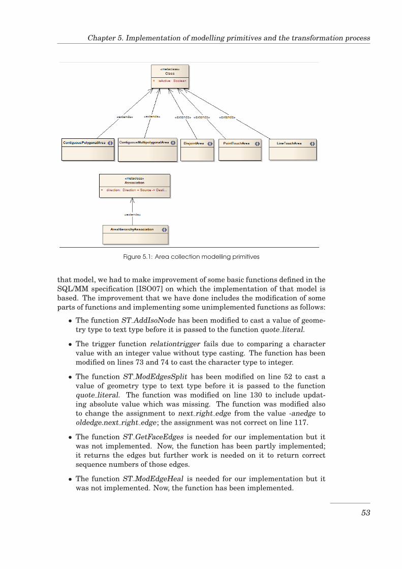
Chapter 5. Implementation of modelling primitives and the transformation process
Figure 5.1: Area collection modelling primitives
that model, we had to make improvement of some basic functions defined in theSQL/MM specification [ISO07] on which the implementation of that model isbased. The improvement that we have done includes the modification of someparts of functions and implementing some unimplemented functions as follows:
• The function ST AddIsoNode has been modified to cast a value of geome-try type to text type before it is passed to the function quote literal.
• The trigger function relationtrigger fails due to comparing a charactervalue with an integer value without type casting. The function has beenmodified on lines 73 and 74 to cast the character type to integer.
• The function ST ModEdgesSplit has been modified on line 52 to cast avalue of geometry type to text type before it is passed to the functionquote literal. The function was modified on line 130 to include updat-ing absolute value which was missing. The function was modified alsoto change the assignment to next right edge from the value -anedge tooldedge.next right edge; the assignment was not correct on line 117.
• The function ST GetFaceEdges is needed for our implementation but itwas not implemented. Now, the function has been partly implemented;it returns the edges but further work is needed on it to return correctsequence numbers of those edges.
• The function ST ModEdgeHeal is needed for our implementation but itwas not implemented. Now, the function has been implemented.
53
5.3. Implementation of the transformation process
5.3 Implementation of the transformation process
In the transformational design, a conceptual schema developed using modellingprimitives undergoes a series of transformations leading to the physical im-plementation of the designed database. The transformation process is semi-automatic; the user can interact with it setting some parameters. The trans-formation process produces a text file containing statements to use to createthe database tables and other related database objects. For the Contiguous-PolygonalArea primitive, the transformation produces also a text file contain-ing statements to use to create maintenance functions. The user can modelcontiguous area collections representable as multipolygons using the Contigu-ousPolygonalArea primitive. In this case, the user represents individual compo-nent polygons and adds more descriptive information in the model to convey thesemantics of ContiguousMultiPolygonalArea primitive. As a result, the trans-formation process will create also the file of functions.
5.3.1 Transformation from conceptual schema to logical schema
The transformation from conceptual to logical schema is implemented using thetransformation capabilities available in Enterprise Architect. Enterprise Archi-tect provides two options for performing model transformation: using transfor-mation definitions and using add-ins [Spa07].
• The Enterprise Architect Add-In Model allows to add functionality to En-terprise Architect using components developed in an application develop-ment tool and then registered in Enterprise Architect. Application devel-opment tools that can be used to develop such components are BorlandDelphi, Microsoft Visual Basic and Microsoft Visual Studio .Net for in-stance.
• Enterprise Architect transformation definitions enable you to transforma model using transformation templates that specify how specific modelelements are transformed.
Transformation definitions provide limited capabilities for the transformationand because of this limitation, add-ins are very often used in them for advancedtransformation tasks such as deleting model element. In our transformationimplementation we use transformation definitions without add-ins, and ad-vanced transformation tasks are performed using a separate transformationtool.
Enterprise Architect comes with a number of standard transformation defini-tions. An example of such transformation definitions is the DDL (Data Defini-tion Language), intended for use in the transformation of database design. Thistransformation definition is shown in Figure 5.2.
A transformation definition consists of a number of transformation templates.The code of a selected transformation template is shown in the transformation
54
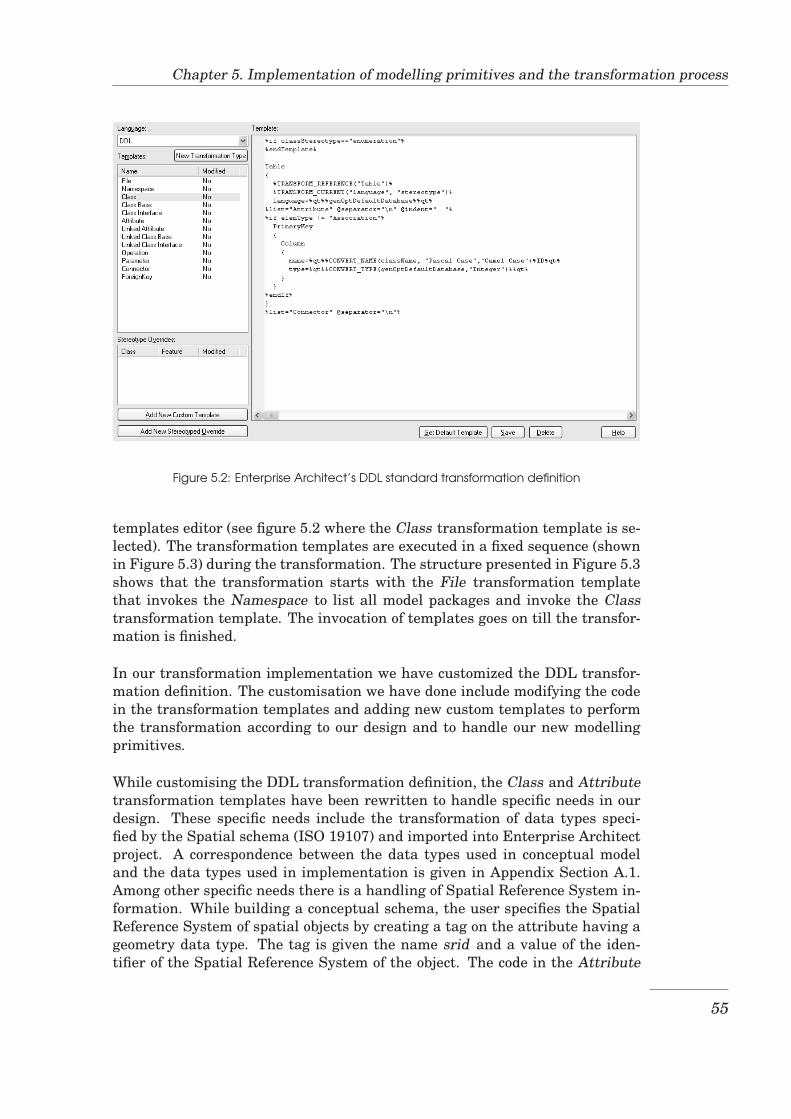
Chapter 5. Implementation of modelling primitives and the transformation process
Figure 5.2: Enterprise Architect’s DDL standard transformation definition
templates editor (see figure 5.2 where the Class transformation template is se-lected). The transformation templates are executed in a fixed sequence (shownin Figure 5.3) during the transformation. The structure presented in Figure 5.3shows that the transformation starts with the File transformation templatethat invokes the Namespace to list all model packages and invoke the Classtransformation template. The invocation of templates goes on till the transfor-mation is finished.
In our transformation implementation we have customized the DDL transfor-mation definition. The customisation we have done include modifying the codein the transformation templates and adding new custom templates to performthe transformation according to our design and to handle our new modellingprimitives.
While customising the DDL transformation definition, the Class and Attributetransformation templates have been rewritten to handle specific needs in ourdesign. These specific needs include the transformation of data types speci-fied by the Spatial schema (ISO 19107) and imported into Enterprise Architectproject. A correspondence between the data types used in conceptual modeland the data types used in implementation is given in Appendix Section A.1.Among other specific needs there is a handling of Spatial Reference System in-formation. While building a conceptual schema, the user specifies the SpatialReference System of spatial objects by creating a tag on the attribute having ageometry data type. The tag is given the name srid and a value of the iden-tifier of the Spatial Reference System of the object. The code in the Attribute
55
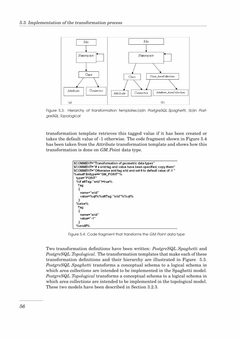
5.3. Implementation of the transformation process
Figure 5.3: Hierarchy of transformation templates:(a)In PostgreSQL Spaghetti, (b)In Post-
greSQL Topological
transformation template retrieves this tagged value if it has been created ortakes the default value of -1 otherwise. The code fragment shown in Figure 5.4has been taken from the Attribute transformation template and shows how thistransformation is done on GM Point data type.
Figure 5.4: Code fragment that transforms the GM Point data type
Two transformation definitions have been written: PostgreSQL Spaghetti andPostgreSQL Topological. The transformation templates that make each of thesetransformation definitions and their hierarchy are illustrated in Figure 5.3.PostgreSQL Spaghetti transforms a conceptual schema to a logical schema inwhich area collections are intended to be implemented in the Spaghetti model.PostgreSQL Topological transforms a conceptual schema to a logical schema inwhich area collections are intended to be implemented in the topological model.These two models have been described in Section 3.2.3.
56
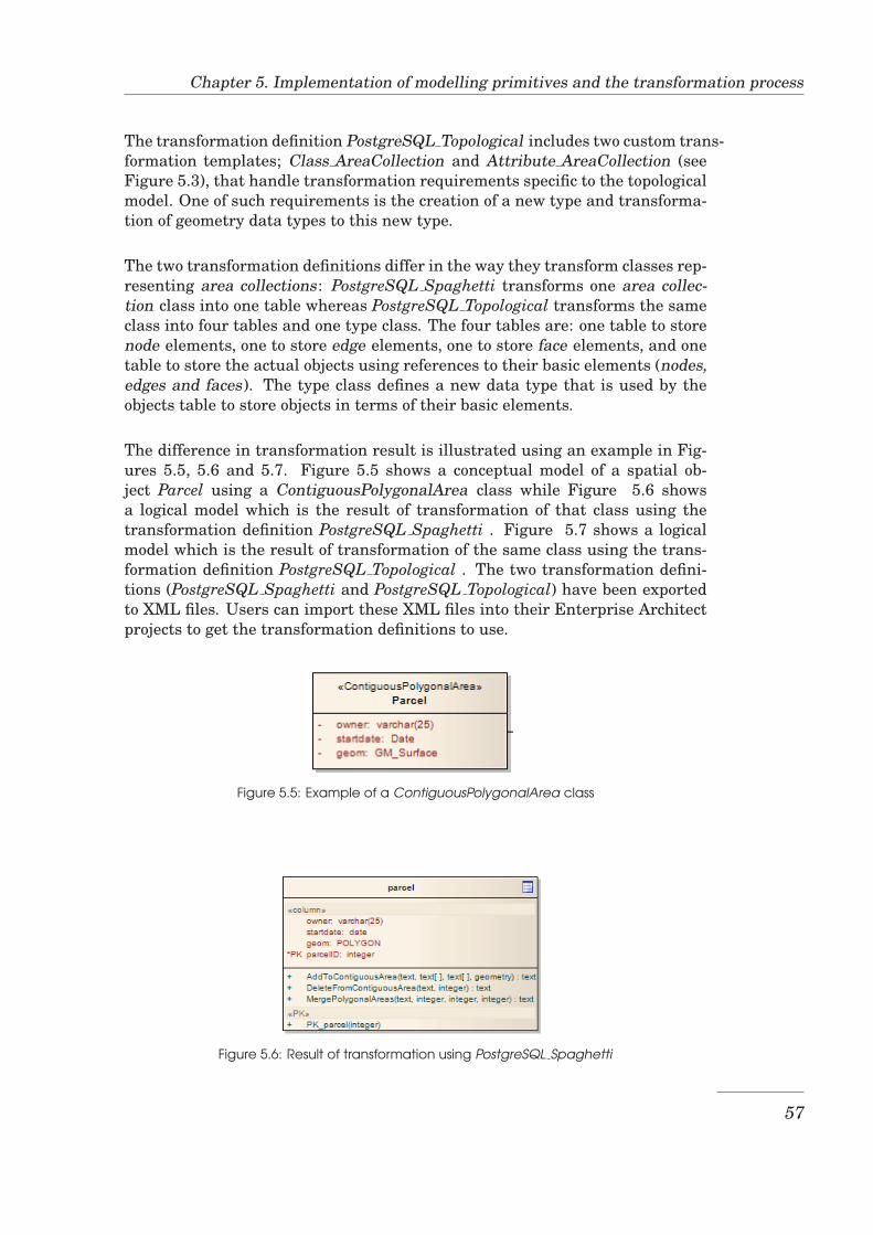
Chapter 5. Implementation of modelling primitives and the transformation process
The transformation definition PostgreSQL Topological includes two custom trans-formation templates; Class AreaCollection and Attribute AreaCollection (seeFigure 5.3), that handle transformation requirements specific to the topologicalmodel. One of such requirements is the creation of a new type and transforma-tion of geometry data types to this new type.
The two transformation definitions differ in the way they transform classes rep-resenting area collections: PostgreSQL Spaghetti transforms one area collec-tion class into one table whereas PostgreSQL Topological transforms the sameclass into four tables and one type class. The four tables are: one table to storenode elements, one to store edge elements, one to store face elements, and onetable to store the actual objects using references to their basic elements (nodes,edges and faces). The type class defines a new data type that is used by theobjects table to store objects in terms of their basic elements.
The difference in transformation result is illustrated using an example in Fig-ures 5.5, 5.6 and 5.7. Figure 5.5 shows a conceptual model of a spatial ob-ject Parcel using a ContiguousPolygonalArea class while Figure 5.6 showsa logical model which is the result of transformation of that class using thetransformation definition PostgreSQL Spaghetti . Figure 5.7 shows a logicalmodel which is the result of transformation of the same class using the trans-formation definition PostgreSQL Topological . The two transformation defini-tions (PostgreSQL Spaghetti and PostgreSQL Topological) have been exportedto XML files. Users can import these XML files into their Enterprise Architectprojects to get the transformation definitions to use.
Figure 5.5: Example of a ContiguousPolygonalArea class
Figure 5.6: Result of transformation using PostgreSQL Spaghetti
57
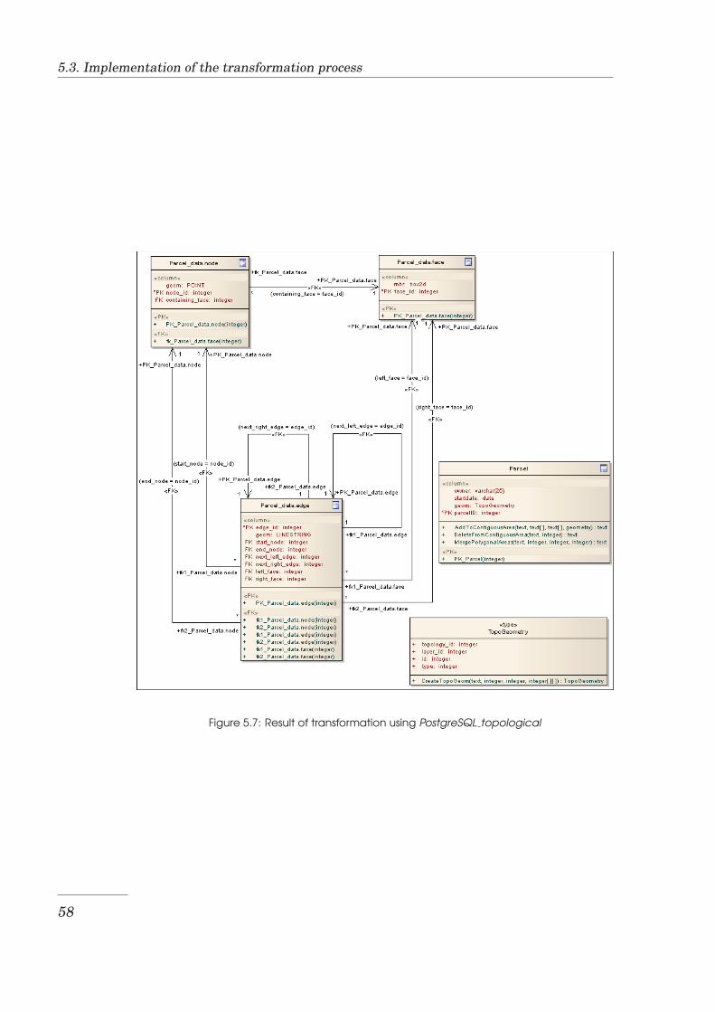
5.3. Implementation of the transformation process
Figure 5.7: Result of transformation using PostgreSQL topological
58
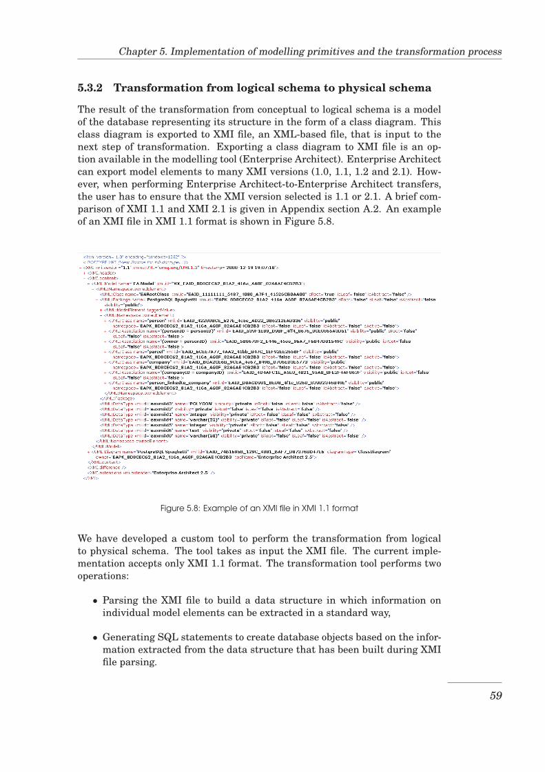
Chapter 5. Implementation of modelling primitives and the transformation process
5.3.2 Transformation from logical schema to physical schema
The result of the transformation from conceptual to logical schema is a modelof the database representing its structure in the form of a class diagram. Thisclass diagram is exported to XMI file, an XML-based file, that is input to thenext step of transformation. Exporting a class diagram to XMI file is an op-tion available in the modelling tool (Enterprise Architect). Enterprise Architectcan export model elements to many XMI versions (1.0, 1.1, 1.2 and 2.1). How-ever, when performing Enterprise Architect-to-Enterprise Architect transfers,the user has to ensure that the XMI version selected is 1.1 or 2.1. A brief com-parison of XMI 1.1 and XMI 2.1 is given in Appendix section A.2. An exampleof an XMI file in XMI 1.1 format is shown in Figure 5.8.
Figure 5.8: Example of an XMI file in XMI 1.1 format
We have developed a custom tool to perform the transformation from logicalto physical schema. The tool takes as input the XMI file. The current imple-mentation accepts only XMI 1.1 format. The transformation tool performs twooperations:
• Parsing the XMI file to build a data structure in which information onindividual model elements can be extracted in a standard way,
• Generating SQL statements to create database objects based on the infor-mation extracted from the data structure that has been built during XMIfile parsing.
59
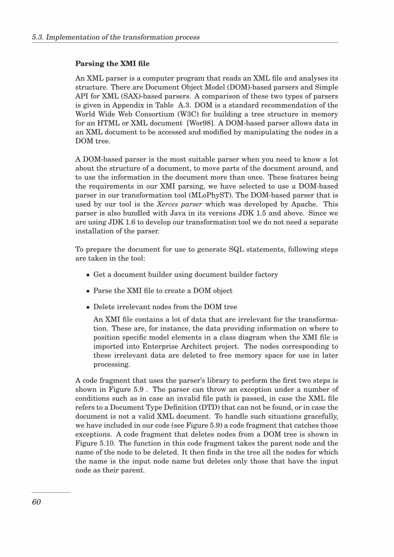
5.3. Implementation of the transformation process
Parsing the XMI file
An XML parser is a computer program that reads an XML file and analyses itsstructure. There are Document Object Model (DOM)-based parsers and SimpleAPI for XML (SAX)-based parsers. A comparison of these two types of parsersis given in Appendix in Table A.3. DOM is a standard recommendation of theWorld Wide Web Consortium (W3C) for building a tree structure in memoryfor an HTML or XML document [Wor98]. A DOM-based parser allows data inan XML document to be accessed and modified by manipulating the nodes in aDOM tree.
A DOM-based parser is the most suitable parser when you need to know a lotabout the structure of a document, to move parts of the document around, andto use the information in the document more than once. These features beingthe requirements in our XMI parsing, we have selected to use a DOM-basedparser in our transformation tool (MLoPhyST). The DOM-based parser that isused by our tool is the Xerces parser which was developed by Apache. Thisparser is also bundled with Java in its versions JDK 1.5 and above. Since weare using JDK 1.6 to develop our transformation tool we do not need a separateinstallation of the parser.
To prepare the document for use to generate SQL statements, following stepsare taken in the tool:
• Get a document builder using document builder factory
• Parse the XMI file to create a DOM object
• Delete irrelevant nodes from the DOM tree
An XMI file contains a lot of data that are irrelevant for the transforma-tion. These are, for instance, the data providing information on where toposition specific model elements in a class diagram when the XMI file isimported into Enterprise Architect project. The nodes corresponding tothese irrelevant data are deleted to free memory space for use in laterprocessing.
A code fragment that uses the parser’s library to perform the first two steps isshown in Figure 5.9 . The parser can throw an exception under a number ofconditions such as in case an invalid file path is passed, in case the XML filerefers to a Document Type Definition (DTD) that can not be found, or in case thedocument is not a valid XML document. To handle such situations gracefully,we have included in our code (see Figure 5.9) a code fragment that catches thoseexceptions. A code fragment that deletes nodes from a DOM tree is shown inFigure 5.10. The function in this code fragment takes the parent node and thename of the node to be deleted. It then finds in the tree all the nodes for whichthe name is the input node name but deletes only those that have the inputnode as their parent.
60
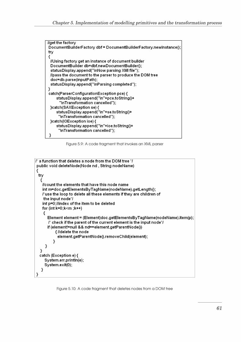
Chapter 5. Implementation of modelling primitives and the transformation process
Figure 5.9: A code fragment that invokes an XML parser
Figure 5.10: A code fragment that deletes nodes from a DOM tree
61
5.3. Implementation of the transformation process
Generating SQL statements for PostgreSQL/PostGIS
After the DOM tree has been built and irrelevant nodes have been deleted,the transformation tool traverses the tree extracting information on model ele-ments to use for generating SQL statements to create database objects neededto implement the model. The steps taken are:
1. Search the tree for the class nodes
2. For each class, identify the class type (table or type) based on the childnode containing the stereotype of the class. Classes representing tablesand types intended to be implemented in a topological model are identi-fied by their names which include a schema name with suffix data thatmust become the topology name. This is done to make sure that properSQL statements are generated to create database objects in the topologi-cal model.
3. Extract table columns and type attributes from the class’child node thatcontains attributes and operations. For each attribute retrieve its prop-erties from the attribute’s child node that contains tag values. The prop-erties meant here are the column/attribute name, column’s default valueif it was specified, whether the column is part of the primary key and ifso the parameters to create the sequence if any are specified. The prop-erties also include whether the column value can be NULL, whether thecolumn is part of a Unique key and the spatial reference system (srid) ifthe column is a geometry column.
4. Generate SQL statements to create sequence and table, type, and topol-ogy, depending on the type of the class and whether the class is to beimplemented in the topological model. Generate statements to add a ge-ometry column to the table and to create a spatial index if the column is ageometry column. In these statements, the information retrieved on step3 is used to specify the properties of columns/attributes including tableand object level constraints such as NOT NULL, UNIQUE and PRIMARYKEY.
5. Extract information contained in association nodes and use this informa-tion to generate statements to create Foreign Key constraints
6. If the model contains area collection classes, generate statements to createmaintenance functions for area collection objects
The transformation tool, MDA Logical to Physical Schema Transformer (MLo-PhyST), has a Graphical User Interface(GUI) that allows the user to select in-put file (the XMI file) and to specify the location and name for the output file.It also has a text area in which it reports to the user about the transformationactivity. A screenshot of this GUI is shown in Figure 5.11.
62
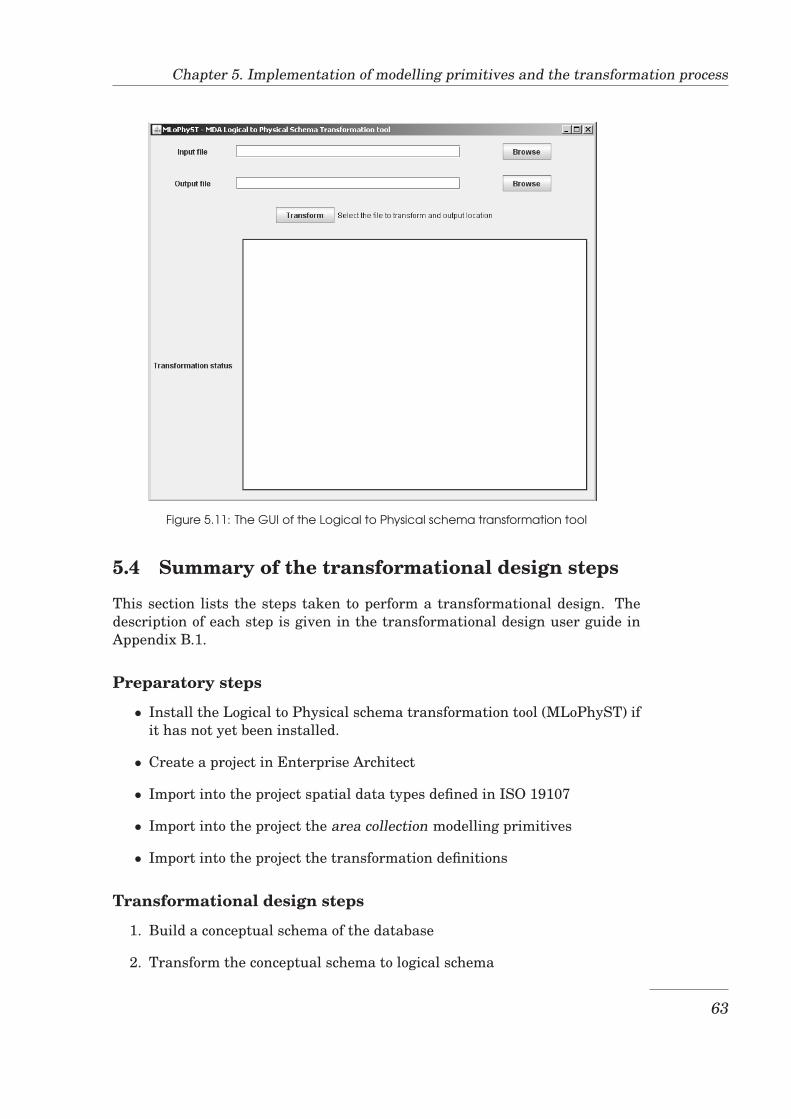
Chapter 5. Implementation of modelling primitives and the transformation process
Figure 5.11: The GUI of the Logical to Physical schema transformation tool
5.4 Summary of the transformational design steps
This section lists the steps taken to perform a transformational design. Thedescription of each step is given in the transformational design user guide inAppendix B.1.
Preparatory steps
• Install the Logical to Physical schema transformation tool (MLoPhyST) ifit has not yet been installed.
• Create a project in Enterprise Architect
• Import into the project spatial data types defined in ISO 19107
• Import into the project the area collection modelling primitives
• Import into the project the transformation definitions
Transformational design steps
1. Build a conceptual schema of the database
2. Transform the conceptual schema to logical schema
63
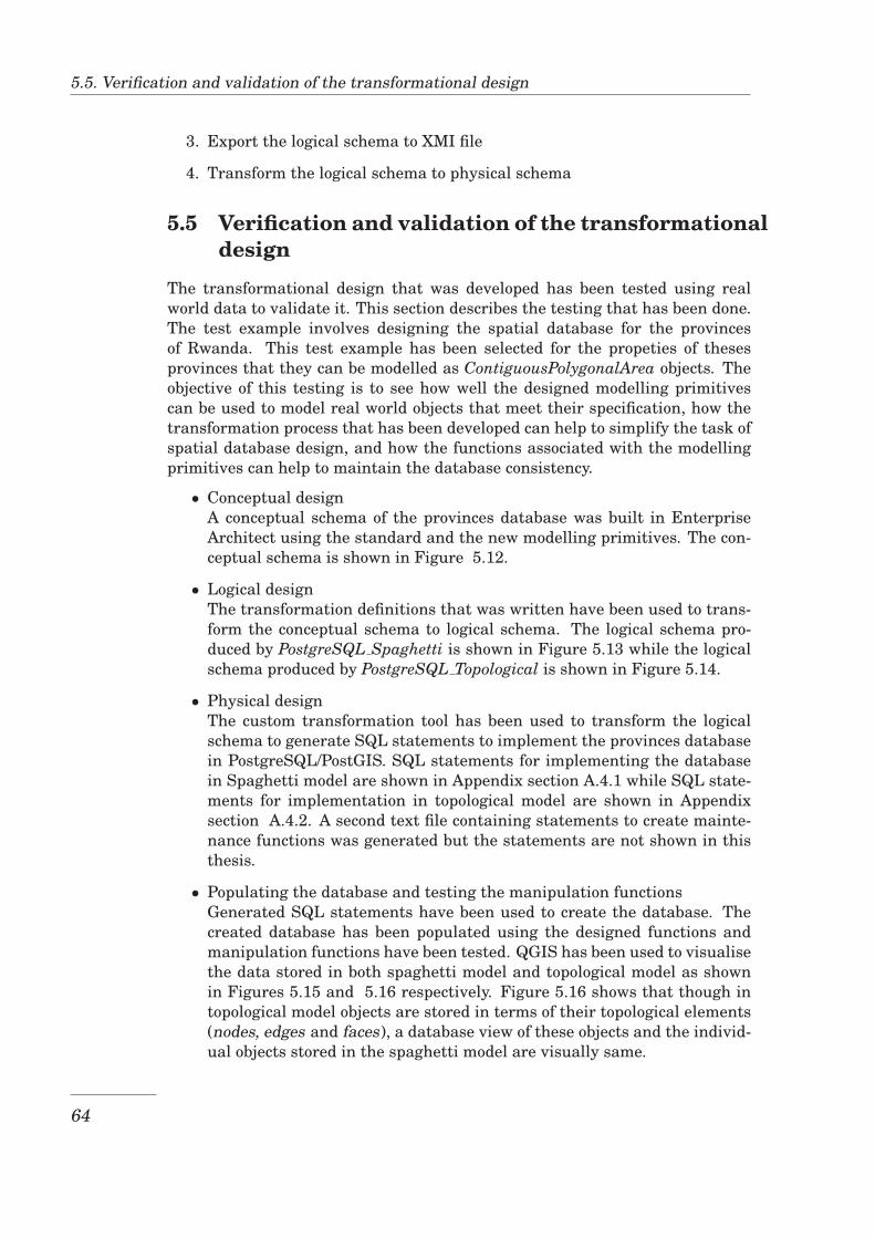
5.5. Verification and validation of the transformational design
3. Export the logical schema to XMI file
4. Transform the logical schema to physical schema
5.5 Verification and validation of the transformationaldesign
The transformational design that was developed has been tested using realworld data to validate it. This section describes the testing that has been done.The test example involves designing the spatial database for the provincesof Rwanda. This test example has been selected for the propeties of thesesprovinces that they can be modelled as ContiguousPolygonalArea objects. Theobjective of this testing is to see how well the designed modelling primitivescan be used to model real world objects that meet their specification, how thetransformation process that has been developed can help to simplify the task ofspatial database design, and how the functions associated with the modellingprimitives can help to maintain the database consistency.
• Conceptual designA conceptual schema of the provinces database was built in EnterpriseArchitect using the standard and the new modelling primitives. The con-ceptual schema is shown in Figure 5.12.
• Logical designThe transformation definitions that was written have been used to trans-form the conceptual schema to logical schema. The logical schema pro-duced by PostgreSQL Spaghetti is shown in Figure 5.13 while the logicalschema produced by PostgreSQL Topological is shown in Figure 5.14.
• Physical designThe custom transformation tool has been used to transform the logicalschema to generate SQL statements to implement the provinces databasein PostgreSQL/PostGIS. SQL statements for implementing the databasein Spaghetti model are shown in Appendix section A.4.1 while SQL state-ments for implementation in topological model are shown in Appendixsection A.4.2. A second text file containing statements to create mainte-nance functions was generated but the statements are not shown in thisthesis.
• Populating the database and testing the manipulation functionsGenerated SQL statements have been used to create the database. Thecreated database has been populated using the designed functions andmanipulation functions have been tested. QGIS has been used to visualisethe data stored in both spaghetti model and topological model as shownin Figures 5.15 and 5.16 respectively. Figure 5.16 shows that though intopological model objects are stored in terms of their topological elements(nodes, edges and faces), a database view of these objects and the individ-ual objects stored in the spaghetti model are visually same.
64
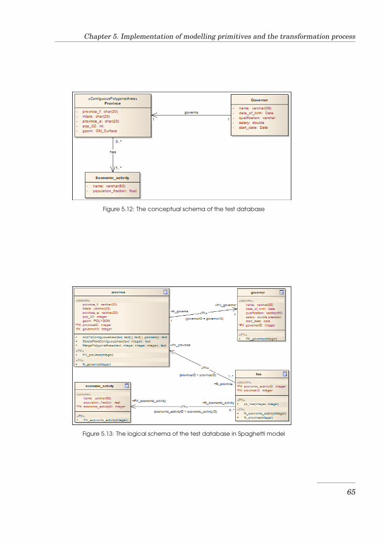
Chapter 5. Implementation of modelling primitives and the transformation process
Figure 5.12: The conceptual schema of the test database
Figure 5.13: The logical schema of the test database in Spaghetti model
65
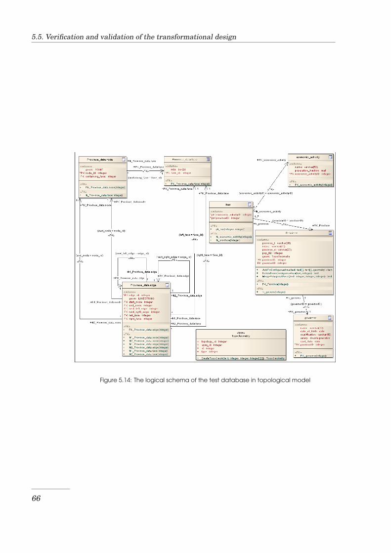
5.5. Verification and validation of the transformational design
Figure 5.14: The logical schema of the test database in topological model
66
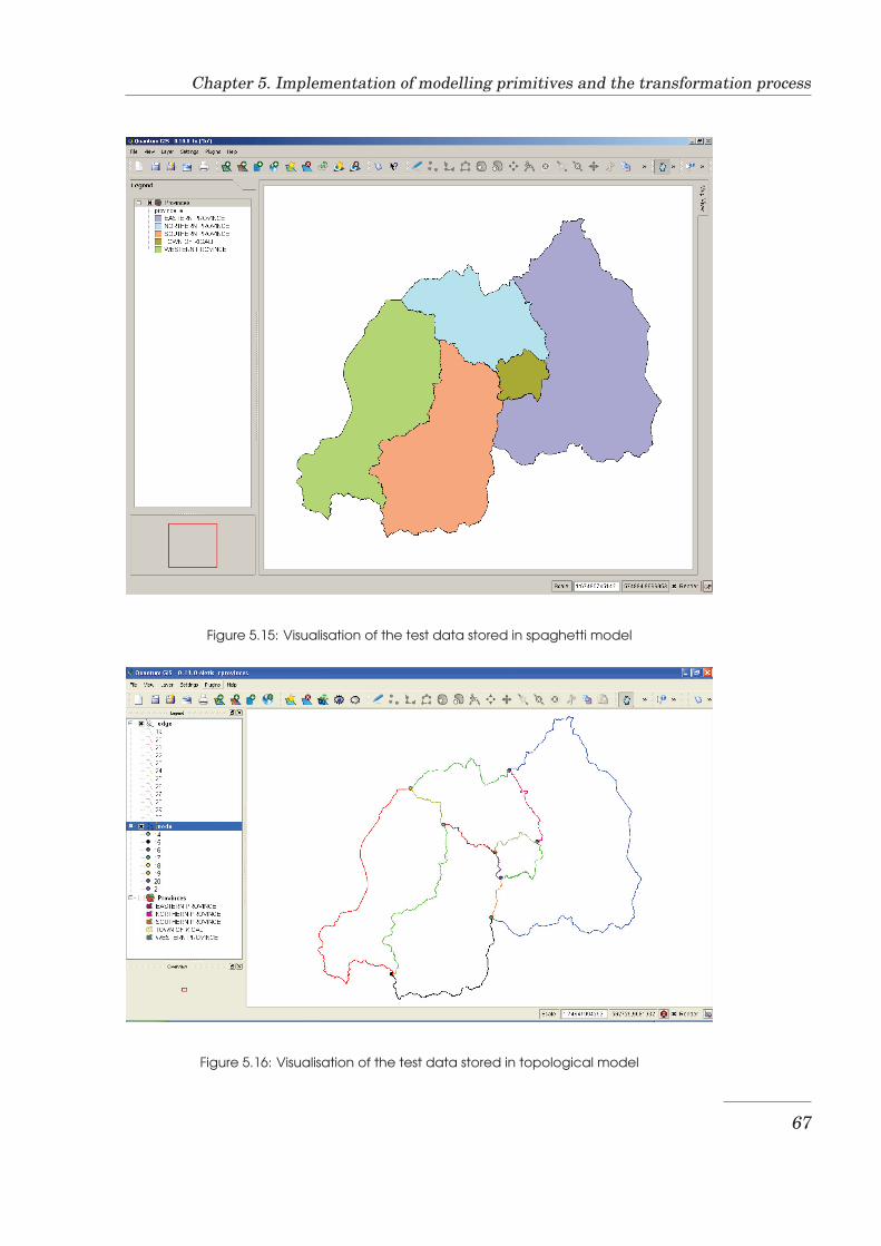
Chapter 5. Implementation of modelling primitives and the transformation process
Figure 5.15: Visualisation of the test data stored in spaghetti model
Figure 5.16: Visualisation of the test data stored in topological model
67

5.5. Verification and validation of the transformational design
68
Chapter 6
Discussion, Conclusions andRecommendations
This chapter presents a summary of the results of this research project, dis-cusses those results, and presents the conclusions drawn from them and therecommendations made for future improvement. Section 6.1 contains the re-sults and their discussion. Section 6.2 contains the conclusions and finally Sec-tion 6.3 presents the recommendations.
6.1 Results and Discussion
The results are presented and discussed with respect to individual researchquestions specified in Section 1.2.2
Identification of feature topology realization options
The main alternatives of realizing the feature topology have been identifiedand presented in Section 3.2.2. These are the Spaghetti model, the Topologicalmodel and the Network model. Some advantages and disadvantages of eachof these models have been described and their current implementation in twoDatabase Management Systems (Oracle and PostgreSQL) has been presentedin brief.
Our observation shows that the Spaghetti model is the mostly adopted alter-native mainly due to its simplicity. This observation agrees with the literature( [The01], [KS00]). However, we argue that to select the appropriate alterna-tive, users should not look at the simplicity only but also at other considerationssuch as those mentionned in Section 3.2.2 .
Extending UML for modelling area feature topology
In Section 4.1, a number of topological classes have been proposed for modellingcollections of area features that display topological dependencies. A modellingprimitive for each topological class has been designed (see Section 4.1) using
69
6.1. Results and Discussion
UML extensibility mechanisms and implemented (see Section 5.2). Each mod-elling primitive is associated with a number of maintenance functions that areused to perform insertion, deletion and modification operations that guaranteetopological robustness. The new modelling primitives have been packaged in aUML profile for use in a modelling tool such as Enterprise Architect.The proposed topological classes do not make an exhaustive list. They havebeen determined based on some specific characteristics of area collections anda different classification is possible by considering other specific characteristics.
Maintenance functions have been developed for area collections representableas polygons that make up a contiguous area without holes. Maintenance func-tions of same purpose as those already developed are proposed for other topo-logical classes. These counterpart functions are easier to implement based onthose already developed, because they need to enforce only some of the con-straints enforced by the already developed functions. For instance, a functionthat inserts a new DisjointArea object will be developed by modifying the func-tion that inserts a new ContiguousPolygonalArea object. This new functionenforces the non-overlapping of objects as done by the existing function butdoes not enforce any other constraint enforced by it. What is specific to thenew function is only to enforce disjointness of the elements of the new object.Furthermore, the development of these functions in the topological model willbe easier because some basic functions needed have been improved or imple-mented during the functional improvement of the topological model that wehave made. The functional improvement that we have made in the topologicalmodel of PostgreSQL/PostGIS is described in Section 5.2.
The class of hierarchies of area collections (AreaHierarchyAssociation) needsan extended study in itself. Some of the issues to be addressed are whether weneed to store the geometries of both the upper level object and the lower levelobject, the types of area collections valid at each level of hierarchy, and howthe AreaHierarchyAssociation associates objects at two different levels of thehierarchy. Once decisions are taken on these issues, developing maintenancefunctions will not be difficult because this class will associate objects of othertopological classes on which maintenance functions will have been developed.
Developing a transformational database design process for thethe realization of area feature topology
A transformational database design process has been developed for the real-ization of area feature topology. It consists of a conceptual design followedby a semi-automatic transformation process. Three schema levels (conceptualschema, logical schema and physical schema) have been described in Section 4.2.The three schemas result from three design levels; conceptual design, logicaldesign and physical design respectively. Splitting the design task into threelevels and performing a transformation of result from one design level to thenext conforms to the principles of the Model Driven Architecture (MDA) thatthis transformational design follows.
70
Chapter 6. Discussion, Conclusions and Recommendations
The design and implementation of the transformation process have been de-scribed in Section 4.2 and 5.3 respectively. A set of rules for transforming aconceptual schema to a logical schema have been described. Two transforma-tion definitions have been developed to perform the conceptual to logical schematransformation for two alternatives of realizing the feature topology. A tool hasbeen developed to transform a logical schema to a physical schema.
The transformation process is semi-automatic which means that the user caninteract with it. From the very beginning, the user makes a choice betweenthe spaghetti and topological models. After the first transformation step, theuser can set various parameters and hence influence the second step of trans-formation. The user can set or change the values of various column/attributeproperties such as UNIQUE and NOT NULL constraints, the parameters ofcreation of sequences for primary key columns and the spatial reference systemidentifiers (srid ) for geometry columns.
While flexibility has been one of the key considerations throughout the designand implementation parts of the research, it has not been provided duringthe transformation of inheritance relationship. We have described three ap-proaches of transforming inheritance hierarchy (one table for the whole inheri-tance hierarchy, one table per inheritance hierarchy branch, and one table pereach class in the inheritance hierarchy). However, the database designer hasnot been given the option to select an approach; only the transformation of eachclass in the hierarchy into a separate table has been provided. Aggregation,composition and association classes have not been handled in the transforma-tion process. This implies that the current transformation implementation willtransform a class which is part of an association class as a standalone class.Similarly, classes in an aggregation or a composition hierarchy will be trans-formed as standalone classes. If such classes contain geometry attributes, thistransformation result will be an indication of wrong choice of modelling primi-tive: the appropriate primitive is the AreaHierarchyAssociation.
In our transformational design, a logical schema has to be exported to XMI filebefore it is transformed to a physical schema. Enterprise Architect can bothgenerate and read XMI file in many versions (1.0, 1.1, 1.2 and 2.1). However,our logical to physical schema transformation tool currently accepts only XMI1.1 format. The decision was due to compatibility issue. Unlike the latest XMIformat (2.1), XMI 1.1 files exported by Enterprise Architect 7.0 (or later) areguaranteed to be correctly imported into earlier versions of Enterprise Archi-tect. It implies that users who move their models between projects are mostlikely to export them to XMI 1.1. Assuming a large number of exported modelsto be in XMI 1.1 format, we want our tool to work on that format at least. Someimplications of using XMI 1.1 instead of XMI 2.1 are described in a brief com-parison of these two versions given in Appendix section A.2, but these cause noserious issues. Moreover, the modularity of the code will make it easy to providesupport for other XMI formats.
71
6.2. Conclusions
Verification and validation of area feature topology modellingprimitives and the transformation process
To verify and validate the modelling primitives, maintenance functions associ-ated with them, and the transformation process developed, a testing has beenperformed with real world data. The testing has been carried out on the classof area collections representable as polygons that make up a contiguous areawithout holes. The testing revealed some problems in the transformation pro-cess which were then fixed. This testing has been described in Section 5.5.
Throughout the design and implementation parts of the research, flexibilityand interoperability have been key considerations. For instance, flexibility isseen in providing transformations for two alternatives of realizing area featuretopology, allowing the database designer to choose among the two. Also duringthe transformation process, the user can set some parameters and hence influ-ence the next transformation step. The interoperability has been taken care ofby making the modelling primitives available in the standard XML file formatthat can be imported into different projects and different modelling tools. Theinteroperability is also supported by the logical to physical schema transforma-tion tool which accepts the logical schema in XMI file. The limitation is that thetransformation definitions used for the first transformation step are written forEnterprise Architect. If a modelling tool other than Enterprise Architect hada way of doing similar first transformation step and could export the result toXMI file, our tool would transform the model.
6.2 Conclusions
With reference to the objectives that have driven this research project, the fol-lowing conclusions are drawn:
• The main feature topology realisation options have been identified andanalysed for their advantages and disadvantages. They are the Spaghettimodel, the Topological model and the Network model.
• A set of primitives have been developed for modelling area feature topol-ogy. This is done by proposing a topological classification for collectionsof area features, then using UML extensibility mechanisms to develop amodelling primitive for each class and associating each primitive with aset of maintenance functions that guarantee topological robustness.
• A transformational database design process has been developed for therealization of area feature topology. To do this, the design task is splitinto three levels (conceptual, logical and physical). Next, a set of trans-formation rules between the results of the design levels are defined, andfinally a semi-automatic transformation process that handles topologicaldefinitions carried by the transformation rules is developed.
• The transformational design process that has been developed provides twoalternatives of realizing area feature topology.
72
Chapter 6. Discussion, Conclusions and Recommendations
• The verification and validation of modelling primitive, associated mainte-nance functions and the transformational design process as a whole hasbeen done. It is done by applying the software testing technique. A testcase is prepared with real world data, modelling primitives are used in thetransformational design and the functions are tested with the test data.
6.3 Recommendations
Based on the results of this research project, the following recommendationsare made for future improvements:
• Extend the work on transformation and maintenance functions to othertopological classes proposed in this research
• Develop more maintenance functions
• Extend the transformation process to handle aggregation, compositionand association classes, and to give the user different inheritance trans-formation strategies to choose from
• Improve the logical to physical schema transformation tool to take inputlogical schema not only in XMI 1.1 format but also in XMI 2.1 format
• Perform also a transformation of functions
• Test maintenance functions on large data sets to evaluate their perfor-mance
Extend the work to other topological classes proposed
Most of the functions proposed for the topological class of area collections rep-resentable as polygons that make up a contiguous area without holes can havetheir counterparts in other topological classes. Since the class worked out is themost restrictive one, counterpart functions in other classes can be developed bystarting with currently implemented functions, deciding the constraints thatshould not be enforced and working out the implication on topology restructur-ing in the topological model. The support for objects with holes can be providedin the topological model by making some modifications to the functions to makethem work also on multiple faces per one object, and then providing a functionto split input objects with holes into faces.
Develop more maintenance functions
This research is the first step towards a library of functions that can enhanceconsistency maintenance in current feature topology realization techniques whileproviding simple interfaces to a range of operations. In particular, such func-tions will shield database designers and users from the complex data structureof the topological model and hence increase its adoption in situations where itis appropriate.
73
6.3. Recommendations
Extend the transformation process
To extend the transformation process to transform association classes, the fol-lowing approach may be used. In the logical schema, create a tag on the tableproduced from the transformation of the association part with a value of the tagassociationclass. Create the same tag on the table produced from the class partwith the value of the class id. In the logical to physical schema transformationtool, use these tag values, which have same name and value, to identify the twotables to generate statements to create only one table out of them but with thecolumns of both. Different inheritance transformation strategies can be imple-mented and the database designer can be asked to set a specific tagged value toindicate the choice on inheritance transformation strategy.
Improve the logical to physical schema transformation tool
The support for XMI 2.1 in the logical to physical schema transformation toolcan be provided by adding a code fragment that extracts the XMI version infor-mation from the root node of the DOM tree and then writing a function to beused to perform structure-dependent operations for XMI 2.1 following the samereasoning as in structure-dependent operations for XMI 1.1.
Perform also a transformation of functions
It is desirable to Integrate the generation of function code into the transforma-tion process such that a modification in the conceptual function is automaticallyreflected in the function code generated.
74
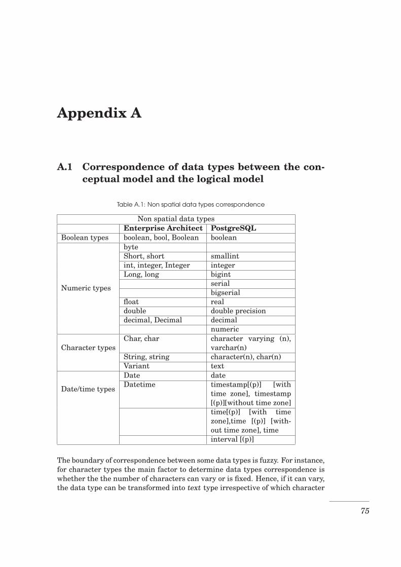
Appendix A
A.1 Correspondence of data types between the con-ceptual model and the logical model
Table A.1: Non spatial data types correspondence
Non spatial data typesEnterprise Architect PostgreSQL
Boolean types boolean, bool, Boolean boolean
Numeric types
byteShort, short smallintint, integer, Integer integerLong, long bigint
serialbigserial
float realdouble double precisiondecimal, Decimal decimal
numeric
Character typesChar, char character varying (n),
varchar(n)String, string character(n), char(n)Variant text
Date/time types
Date dateDatetime timestamp[(p)] [with
time zone], timestamp[(p)][without time zone]time[(p)] [with timezone],time [(p)] [with-out time zone], timeinterval [(p)]
The boundary of correspondence between some data types is fuzzy. For instance,for character types the main factor to determine data types correspondence iswhether the the number of characters can vary or is fixed. Hence, if it can vary,the data type can be transformed into text type irrespective of which character
75
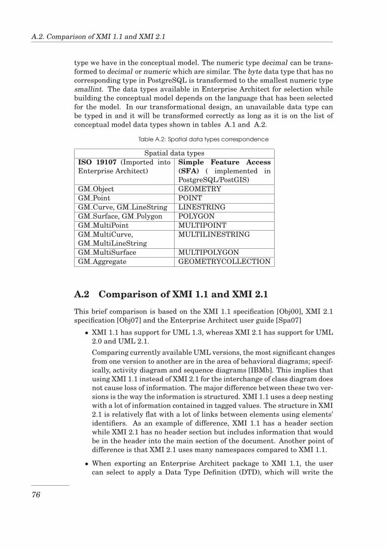
A.2. Comparison of XMI 1.1 and XMI 2.1
type we have in the conceptual model. The numeric type decimal can be trans-formed to decimal or numeric which are similar. The byte data type that has nocorresponding type in PostgreSQL is transformed to the smallest numeric typesmallint. The data types available in Enterprise Architect for selection whilebuilding the conceptual model depends on the language that has been selectedfor the model. In our transformational design, an unavailable data type canbe typed in and it will be transformed correctly as long as it is on the list ofconceptual model data types shown in tables A.1 and A.2.
Table A.2: Spatial data types correspondence
Spatial data typesISO 19107 (Imported intoEnterprise Architect)
Simple Feature Access(SFA) ( implemented inPostgreSQL/PostGIS)
GM Object GEOMETRYGM Point POINTGM Curve, GM LineString LINESTRINGGM Surface, GM Polygon POLYGONGM MultiPoint MULTIPOINTGM MultiCurve,GM MultiLineString
MULTILINESTRING
GM MultiSurface MULTIPOLYGONGM Aggregate GEOMETRYCOLLECTION
A.2 Comparison of XMI 1.1 and XMI 2.1
This brief comparison is based on the XMI 1.1 specification [Obj00], XMI 2.1specification [Obj07] and the Enterprise Architect user guide [Spa07]
• XMI 1.1 has support for UML 1.3, whereas XMI 2.1 has support for UML2.0 and UML 2.1.Comparing currently available UML versions, the most significant changesfrom one version to another are in the area of behavioral diagrams; specif-ically, activity diagram and sequence diagrams [IBMb]. This implies thatusing XMI 1.1 instead of XMI 2.1 for the interchange of class diagram doesnot cause loss of information. The major difference between these two ver-sions is the way the information is structured. XMI 1.1 uses a deep nestingwith a lot of information contained in tagged values. The structure in XMI2.1 is relatively flat with a lot of links between elements using elements’identifiers. As an example of difference, XMI 1.1 has a header sectionwhile XMI 2.1 has no header section but includes information that wouldbe in the header into the main section of the document. Another point ofdifference is that XMI 2.1 uses many namespaces compared to XMI 1.1.
• When exporting an Enterprise Architect package to XMI 1.1, the usercan select to apply a Data Type Definition (DTD), which will write the
76
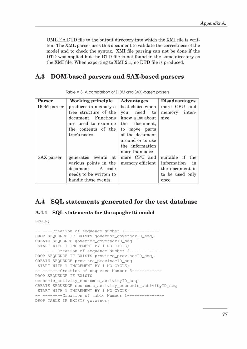
Appendix A.
UML EA.DTD file to the output directory into which the XMI file is writ-ten. The XML parser uses this document to validate the correctness of themodel and to check the syntax. XMI file parsing can not be done if theDTD was applied but the DTD file is not found in the same directory asthe XMI file. When exporting to XMI 2.1, no DTD file is produced.
A.3 DOM-based parsers and SAX-based parsers
Table A.3: A comparison of DOM and SAX -based parsers
Parser Working principle Advantages DisadvantagesDOM parser produces in memory a
tree structure of thedocument. Functionsare used to examinethe contents of thetree’s nodes
best choice whenyou need toknow a lot aboutthe document,to move partsof the documentaround or to usethe informationmore than once
more CPU andmemory inten-sive
SAX parser generates events atvarious points in thedocument. A codeneeds to be written tohandle those events
more CPU andmemory efficient
suitable if theinformation inthe document isto be used onlyonce
A.4 SQL statements generated for the test database
A.4.1 SQL statements for the spaghetti modelBEGIN;
-- ----Creation of sequence Number 1--------------DROP SEQUENCE IF EXISTS governor_governorID_seq;CREATE SEQUENCE governor_governorID_seqSTART WITH 1 INCREMENT BY 1 NO CYCLE;
-- ------Creation of sequence Number 2-------------DROP SEQUENCE IF EXISTS province_provinceID_seq;CREATE SEQUENCE province_provinceID_seqSTART WITH 1 INCREMENT BY 1 NO CYCLE;
-- -------Creation of sequence Number 3------------DROP SEQUENCE IF EXISTSeconomic_activity_economic_activityID_seq;CREATE SEQUENCE economic_activity_economic_activityID_seqSTART WITH 1 INCREMENT BY 1 NO CYCLE;
-- --------Creation of table Number 1---------------DROP TABLE IF EXISTS governor;
77
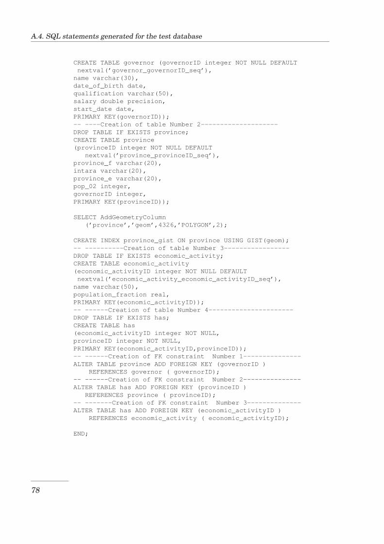
A.4. SQL statements generated for the test database
CREATE TABLE governor (governorID integer NOT NULL DEFAULTnextval(’governor_governorID_seq’),name varchar(30),date_of_birth date,qualification varchar(50),salary double precision,start_date date,PRIMARY KEY(governorID));-- ----Creation of table Number 2--------------------DROP TABLE IF EXISTS province;CREATE TABLE province(provinceID integer NOT NULL DEFAULT
nextval(’province_provinceID_seq’),province_f varchar(20),intara varchar(20),province_e varchar(20),pop_02 integer,governorID integer,PRIMARY KEY(provinceID));
SELECT AddGeometryColumn(’province’,’geom’,4326,’POLYGON’,2);
CREATE INDEX province_gist ON province USING GIST(geom);-- ----------Creation of table Number 3-----------------DROP TABLE IF EXISTS economic_activity;CREATE TABLE economic_activity(economic_activityID integer NOT NULL DEFAULTnextval(’economic_activity_economic_activityID_seq’),name varchar(50),population_fraction real,PRIMARY KEY(economic_activityID));-- ------Creation of table Number 4----------------------DROP TABLE IF EXISTS has;CREATE TABLE has(economic_activityID integer NOT NULL,provinceID integer NOT NULL,PRIMARY KEY(economic_activityID,provinceID));-- ------Creation of FK constraint Number 1---------------ALTER TABLE province ADD FOREIGN KEY (governorID )
REFERENCES governor ( governorID);-- ------Creation of FK constraint Number 2---------------ALTER TABLE has ADD FOREIGN KEY (provinceID )
REFERENCES province ( provinceID);-- -------Creation of FK constraint Number 3--------------ALTER TABLE has ADD FOREIGN KEY (economic_activityID )
REFERENCES economic_activity ( economic_activityID);
END;
78
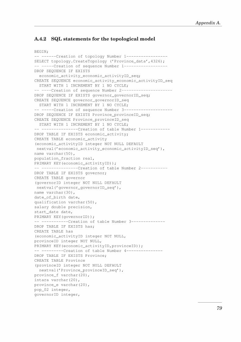
Appendix A.
A.4.2 SQL statements for the topological model
BEGIN;-- ------Creation of topology Number 1-----------------SELECT topology.CreateTopology (’Province_data’,4326);-- -----Creation of sequence Number 1------------------DROP SEQUENCE IF EXISTS
economic_activity_economic_activityID_seq;CREATE SEQUENCE economic_activity_economic_activityID_seq
START WITH 1 INCREMENT BY 1 NO CYCLE;-- ----Creation of sequence Number 2---------------------DROP SEQUENCE IF EXISTS governor_governorID_seq;CREATE SEQUENCE governor_governorID_seq
START WITH 1 INCREMENT BY 1 NO CYCLE;-- -----Creation of sequence Number 3--------------------DROP SEQUENCE IF EXISTS Province_provinceID_seq;CREATE SEQUENCE Province_provinceID_seq
START WITH 1 INCREMENT BY 1 NO CYCLE;-- ---------------Creation of table Number 1------------DROP TABLE IF EXISTS economic_activity;CREATE TABLE economic_activity(economic_activityID integer NOT NULL DEFAULTnextval(’economic_activity_economic_activityID_seq’),
name varchar(50),population_fraction real,PRIMARY KEY(economic_activityID));-- ---------------Creation of table Number 2-----------DROP TABLE IF EXISTS governor;CREATE TABLE governor(governorID integer NOT NULL DEFAULTnextval(’governor_governorID_seq’),
name varchar(30),date_of_birth date,qualification varchar(50),salary double precision,start_date date,PRIMARY KEY(governorID));-- -----------Creation of table Number 3--------------DROP TABLE IF EXISTS has;CREATE TABLE has(economic_activityID integer NOT NULL,provinceID integer NOT NULL,PRIMARY KEY(economic_activityID,provinceID));-- ---------Creation of table Number 4---------------DROP TABLE IF EXISTS Province;CREATE TABLE Province(provinceID integer NOT NULL DEFAULT
nextval(’Province_provinceID_seq’),province_f varchar(20),intara varchar(20),province_e varchar(20),pop_02 integer,governorID integer,
79

A.4. SQL statements generated for the test database
PRIMARY KEY(provinceID));
SELECT topology.AddTopoGeometryColumn(’Province_data’,CAST(current_schema() AS text),’Province’,’geom’,’POLYGON’);-- -------Creation of FK constraint Number 1---------------ALTER TABLE has ADD FOREIGN KEY (economic_activityID )REFERENCES economic_activity ( economic_activityID);-- -----Creation of FK constraint Number 2----------------ALTER TABLE Province ADD FOREIGN KEY (governorID )REFERENCES governor ( governorID);-- -----Creation of FK constraint Number 3---------------ALTER TABLE has ADD FOREIGN KEY (provinceID )REFERENCES Province ( provinceID);
END;
80
Appendix B
B.1 Transformational design user guide
This sections describes the steps taken to perform a transformational design ofspatial database using the transformation process and the modelling primitivesdeveloped in this research.
Preparatory steps
• Install the Logical to Physical schema transformation tool (MLoPhyST)If you have not yet installed the Logical to Physical schema transforma-tion tool, install it now. The tool is installed once and you can use it untilyou uninstall it.
• Create a project in Enterprise Architect
• Import into the project Spatial data types defined in ISO 19107Select the root node in the Project browser then go to Project menu:Project > Import/Export > Import Package from XMI. Select the fileISO19107Package.xml and import it.
• Import into the project the area collection modelling primitivesSwitch from the Project browser to Resources, right-click on UMLProfiles and select Import Profile. Select the file areaCollections.xmland import it.
• Import into the project the transformation definitionsGo to Tools menu. Tools > Import Reference Data, then select the filePostgreSQL Spaghetti.xml and import it. Repeat this step to import thefile PostgreSQL Topological.xml.
Transformational design steps
1. Build a conceptual schema of the databaseOpen the project you created and build your conceptual schema. Areacollections modelling primitives are available in the toolbox by selectingMore tools > AreaCollections. To specify the Spatial Reference Systemon a class, select the attibute with a geometry data type and create atagged value with the name srid and the Spatial Reference System as the
81
B.1. Transformational design user guide
value. To set a UNIQUE constraint on a future column, select the staticproperty on the corresponding attribute from the attribute’s properties.
2. Transform the conceptual schema to logical schemaIn the Project browser, select the package containing the class dia-gram to transform. Go to Project menu: Project > Transformations >Transform Current Package. In the list of transformations, select thetransformation definition to use and the package to contain the transfor-mation output. If you want to transform the schema to logical schemain which area collections are to be implemented in Spaghetti model, selectthe PostgreSQL Spaghetti transformation definition. For implementationin topological model, select the PostgreSQL Topological transformationdefinition. Select click Do Transform to run the transformation. Afterthe transformation, you can open the output logical schema and modifysome parameters if you need to. To see the parameters that can be mod-ified, select the table column of interest and check the available taggedvalues. For instance, you can disable the creation of a sequence numberfor a primary key column by selecting the primary key column and modi-fying the tagged value setting AutoNum=1 to AutoNum=0.
3. Export the logical schema to XMI fileFrom the Project browser, select the package containing the logicalschema. Make sure that if you have nested packages, you select the innerpackage. Go to Project menu: Project > Import/Export > Export Pack-age to XMI. Select the location and name for the output file. In the areaFor Export to Other Tools, select UML 1.3 (XMI 1.1) for the fieldXMI Type. Click Export to export the package
4. Transform the logical schema to physical schemaLaunch the Logical-to-Physical schema transformation tool. For the fieldInput file, select the XML file produced in step 3. Select the locationand name for the output file. Click Transform to run the transformation.
Post design steps
1. Database creationThe result of the transformational design is a text file ( .sql) containing thestatements for creating the database objects in PostgreSQL/PostGIS. Ifthe model contains area collections, another text file (.sql) will be created.The statements in this second file will be executed to create maintenancefunctions. At this step, if the design contains area collections intended tobe implemented in Spaghetti model or contains no area collections, youcan execute the statements in the output file to create database objects. Ifthe design contains area collections intended to be implemented in topo-logical model, you need first to make sure that the topological model hasbeen enabled in your PostgreSQL/PostGIS installation.
2. Database populationAfter the database objects have been created, the database can be popu-
82

Appendix B.
lated. Standard methods (insertion of objects one by one or bulk loading)can be used, however to preserve topological relationships of area collec-tion objects you use the functions created as part of this implementation.Functions to be used in the topological model are located in the Topologyschema whereas functions to be used in Spaghetti model are located inthe Public schema.
3. Data manipulationLikewise, you use the functions created as part of this implementationto manipulate area collections objects without violating topological rela-tionships. Currently, manipulation functions available are those to deleteobjects from a contiguous area and those to merge objects in a contiguousarea.
83

B.1. Transformational design user guide
84
Bibliography
[Amb04] Scott W. Ambler, The Object Primer, 3 ed., Cambridge UniversityPress, Cambridge, 2004.
[AN05] Jim Arlow and Ila Neustadt, UML 2 and the unified process : practicalobject - oriented analysis and design, 2 ed., Object technology series,Addison Wesley, Upper Saddle River, NJ 07458, 2005.
[BP98] Michael Blaha and William Premerlani, Object-Oriented modeling andDesign for Database Applications, Prantice-Hall, Upper Saddle River,NJ 07458, 1998.
[CF96] Eliseo Clementini and Paolino Di Felice, A model for representingtopological relationships between complex geometric features in spatialdatabases, Information Sciences 90 (1996), no. 1-4, 121–136.
[CJE94] Eliseo Clementini, Sharma J., and Max J. Egenhofer, Modeling Topo-logical Spatial Relations: Strategies for Query Processing, Interna-tional Journal of Computer and Graphics 18 (1994), no. 6, 815–822.
[ECF94] Max J. Egenhofer, Eliseo Clementini, and Paolino Di Felice, Topologi-cal relations between regions with holes, International Journal of Geo-graphical Information Systems 8 (1994), 129–142.
[EF91] Max J. Egenhofer and Robert D. Franzosa, Point-Set Topological Rela-tions, International Journal for Geographical Information Systems 5(1991), no. 2, 161 – 174.
[Ege89] Max J. Egenhofer, A Formal Definition of Binary Topological Relation-ships, Lecture Notes in Computer Science, vol. 367, pp. 457 – 472,Springer-Verlag, June 1989.
[EN07] Ramez Elmasri and Shamkant B. Navathe, Fundamentals of DatabaseSystems, 5 ed., Addison Wesley, Boston, USA, 2007.
[HMM03] Erik Hoel, Sudhakar Menon, and Scott Morehouse, Building a Ro-bust Relational Implementation of Topology, Lecture Notes in Com-puter Science, vol. 2750/2003, pp. 508–509, Springer Berlin / Heidel-berg, 2003.
[IBMa] IBM, Rational Rose, http://www-01.ibm.com/software/awdtools/developer/rose/index.html, accessed: 27-12-2008.
85
Bibliography
[IBMb] , UML 1.4 and 2.x notation mapping, http://publib.boulder.ibm.com/infocenter/rsmhelp/v7r5m0/index.jsp?topic=/com.ibm.xtools.petal.ui.doc/topics/rmappingoview.html, accessed: 10-02-2009.
[ISO03] ISO, ISO 19107: Geographic information - Spatial schema, Interna-tional standard, ISO, Geneva, May 2003.
[ISO07] ISO/IEC, Information technology Database languages SQL Multime-dia and Application Packages - Part 3: Spatial, International stan-dard, ISO/IEC, May 2007.
[JBR98] Ivar Jacobson, Grady Booch, and Jim Rumbaugh, The Unified Mod-eling Language Reference Manual, Addison Wesley, Reading, Mas-sachusetts 01867, 1998.
[JBR99] , The unified software development process UML, Object tech-nology series, Addison Wesley, Upper Saddle River, NJ 07458, 1999.
[KS00] Gabriel Kuper and Michel Scholl, Geographic Information Systems,Constraint databases, ch. 8, pp. 175–198, Springer, Berlin, 2000.
[MM03] Joaquin Miller and Jishnu Mukerji, MDA Guide Version 1.0.1, Tech.report, Object Management Group (OMG), June 2003.
[MP01] Wai Yin Mok and David P. Paper, On Transformations from UML Mod-els to Object-Relational Databases, IEEE Computer Society Digital Li-brary 3 (2001).
[Mur03] Chuck Murray, Oracle Spatial Topology and Network Data models,10g Release 1 (10.1), Tech. report, Oracle Corporation, Nashua, NH03062-2804, USA, December 2003.
[MVC03] Esperanza Marcos, Belen Vela, and Jose Marıa Cavero, A Method-ological Approach for Object-Relational Database Design using UML,Software and Systems Modeling 2 (2003), no. 1, 59–72.
[Obj00] Object Management Group, OMG XML Metadata Interchange (XMI)Specification, Version 1.1, OMG specification, Object ManagementGroup, November 2000.
[Obj05] , Meta Object Facility (MOF) Specification, Version 1.4.1, OMGspecification, Object Management Group, July 2005.
[Obj07] , MOF 2.0/XMI Mapping Specification, Version 2.1.1, OMGspecification, Object Management Group, December 2007.
[Ope05] Open Geospatial Consortium, Interoperability & Open Architectures:An Analysis of Existing Standardisation Processes & Procedures,White paper, Open Geospatial Consortium, 2005, Version: 1.0.
86
Bibliography
[Ope06] Open Geospatial Consortium Inc., OpenGIS Implementation Specifica-tion for Geographic information - Simple feature access - Part 1: Com-mon architecture, implementation specification, Open Geospatial Con-sortium Inc., October 2006, Version: 1.2.0.
[OS02] Olaf M. Ostensen and Paul C. Smits, ISO/TC211: standardisationof Geographic Information and Geo-Informatics, IEEE Transaction onGeoscience and Remote Sensing 1 (2002), 261–263.
[PM07] Oscar Pastor and Juan Carlos Molina, Model-Driven Architecture inPractice, Springer-Verlag, Berlin, Germany, 2007.
[Pos08] PostgreSQL Global Development Group, PostgreSQL 8.3.0 Documen-tation, http://www.postgresql.org/files/documentation/pdf/8.3/postgresql-8.3-A4.pdf, 2008, accessed: 30-09-2008.
[Ref05] Refractions Research, Postgis Topology, http://postgis.refractions.net/support/wiki/index.php?PostgisTopology, October 2005, accessed: 12-08-2008.
[RSV02] Philippe Rigaux, Michel Scholl, and Agnes Voisard, Spatial databaseswith application to GIS, Morgan Kaufmann Publishers Inc., San Fran-cisco, CA, USA, 2002.
[SB06] Markus Schneider and Thomas Behr, Topological Relationships Be-tween Complex Spatial Objects, ACM Transactions on Database Sys-tems 31 (2006), no. 1, 39–81.
[Spa] Sparx Systems, Enterprise Architect, http://www.sparxsystems.com.au/products/ea/index.html, accessed: 27-12-2008.
[Spa07] , Enterprise Architect User Guide, 2007, Version 7.0.
[The01] David M. Theobald, Topology revisited: representing spatial relations,International Journal of Geographical Information Science 15 (2001).
[vBM08] Jan van Bennekom-Minnema, The Land Administration DomainModel ’Survey Package’ and Model Driven Architecture, Master’s the-sis, Delft University of Technology, 2008.
[WK03] Jos Warmer and Anneke Kleppe, The Object Constraint Language:Getting your models ready for MDA, 2 ed., Object Technology, Addison-Wesley, Boston, MA 02116, August 2003.
[Wor98] World Wide Web Consortium, Document Object Model (DOM)Level 1 Specification, Version 1.0, W3C Recommendation, WorldWide Web Consortium, October 1998, http://www.w3.org/TR/REC-DOM-Level-1/.
[WR07] Fei Wang and Wolfgang Reinhardt, Extending Geographic Data Model-ing by Adopting Constraint Decision Table to Specify Spatial IntegrityConstraints, The European Information Society, pp. 435–454, SpringerBerlin Heidelberg, 2007.
87