Embed Size (px)
Citation preview

California Test 231 STATE OF CALIFORNIA—BUSINESS, TRANSPORTATION AND HOUSING AGENCY March 2013
DEPARTMENT OF TRANSPORTATION DIVISION OF ENGINEERING SERVICES Transportation Laboratory 5900 Folsom Blvd. Sacramento, California 95819-4612
METHOD OF TEST FOR RELATIVE COMPACTION OF UNTREATED AND TREATED SOILS AND AGGREGATES
USING NUCLEAR GAGES
A. SCOPE This test method describes the procedure for selecting a test area for the determination of in-place wet density and moisture content of untreated and treated soils and aggregates by the use of a nuclear gage and the determination of relative compaction. This test method includes two parts: 1. Determination of In-Place Wet Density and Moisture Content.
2. Determination of Relative Compaction. B. REFERENCES California Test 111 – Developing Density and Moisture Calibration Tables for Nuclear Gages California Test 216 – Relative Compaction of Untreated and Treated Soils and Aggregates C. APPARATUS
1. Nuclear Gage: a portable instrument containing radioactive sources, detectors, electronics and battery packs. The instrument must be calibrated in accordance with California Test 111.
NOTE: Gages with DIRECT READOUT Capability may be used to determine
density and moisture. 2. Reference Standard Block: a block provided by the gage manufacturer primarily
for checking instrument operation and for establishing standard counts against which future measurements are compared.
3. Metal Guide Plate: the guide plate should be no smaller in any dimension than
the footprint of the nuclear gage. The plate must be flat to a tolerance of 1⁄16 in. in any plane.
4. Pin: meets the gage manufacturer’s specifications or suitable equipment (e.g., slide hammer, drill) capable of producing a hole meeting the manufacturer’s
requirements and without disturbing the surrounding material to be tested.
California Test 231 March 2013
- 2 -
D. PROCEDURES PART 1. DETERMINATION OF IN-PLACE WET DENSITY AND MOISTURE CONTENT 1A. STANDARDIZATION OF NUCLEAR GAGE FOR WET DENSITY AND MOISTURE CONTENT
1. Follow manufacturer’s instruction for start-up.
2. Set the manufacturer’s reference standard block a minimum of 5 ft from any
object and a minimum of 25 ft from any other nuclear gage to avoid any influence to the readings.
3. Place the gage on the reference standard block in the closed (safe) position and
take one 4 min density and moisture counts. Record the data on the Relative Compaction Test – Nuclear Report form (Form TL 2148 – Figure 3, Column A for density and Column E for moisture) and on the gage logbook.
NOTE: The 4 min counts are required to be within the acceptable deviation
limits (ADL) stated in the most recent calibration table (within the last 12 months) established in accordance with California Test 111. Otherwise, the gage cannot be used.
1B. SITE PREPARATION
1. Remove all loose surface material and prepare a flat, smooth surface large enough to seat the guide plate. In a location where sheeps-foot and similar type tamping rollers have been used, remove the loose surface material to a depth below the deepest penetration by the roller to produce a flat and smooth surface within 1⁄8 in. in any plane. If necessary, use native fines that pass a No. 4 sieve to fill minor depressions and protrusions, or to correct a slight lack of plane. Tamp fines and any loose material with the guide plate.
2. Make a hole using the pin and guide plate. A drill or slide hammer may be used
in lieu of the pin. The depth of hole must be 2 in. deeper than the transmission depth. This hole must be as close to 90º from the plane surface as possible. NOTE: If the plate is rotated slightly around the pin and the plate does not make
contact with the ground or if it appears that the hole is not straight make a new hole at the immediate adjacent area provided that the previous hole is not within the footprint of the gage.
1C. FIELD TEST FOR WET DENSITY
1. At all pre-determined test sites, place the nuclear gage on the prepared surface so that the bottom of the gage is firmly seated in direct contact with the soil. Insert the source rod into the hole to the predetermined transmission depth. Adjust the gage so the source rod is firmly against the side of the hole nearest to the gage and take a 1 min density count. Record the data on Form TL 2148.
NOTE: No obstruction or foreign element should be within a distance of 8 in.
from the sides of the source-detector axis. Wet density measurements are made in the direct transmission position where the rod is placed into the ground.

California Test 231 March 2013
- 3 -
Select a direct transmission depth as close as possible to but not equal to or greater than, the thickness of material being tested, i.e., use a 3 in. direct transmission depth and corresponding calibration to test a layer of material 4 in. thick and use a 5 in. direct transmission depth and corresponding calibration to test a layer of material 6 in. thick.
2. Average counts from all test sites and determine count ratio by dividing the
average field count by the average standard count. 3. Find the average count ratio and corresponding direct transmission average wet
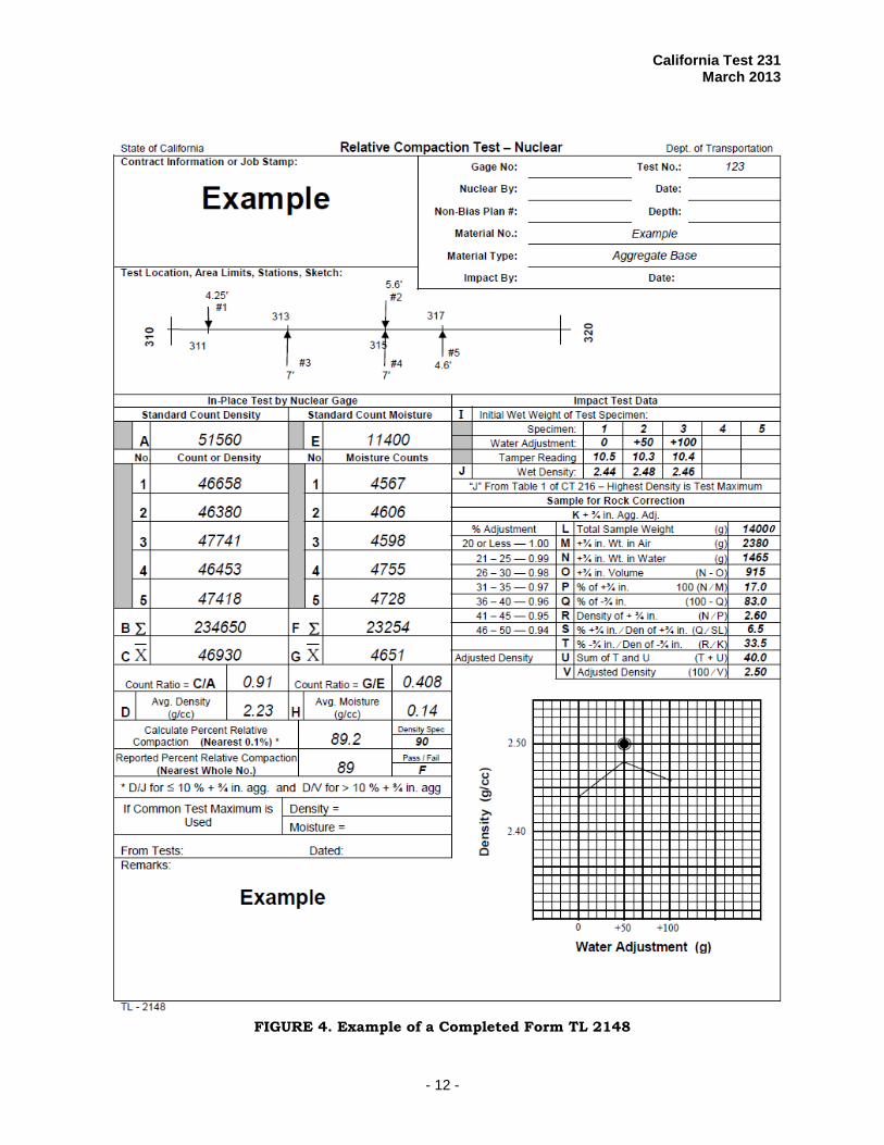
density (g/cc). Record the data on Form TL 2148. An example is shown in Figure 4. NOTE: Gages with DIRECT READOUT capability may be used to determine
density in accordance with California Test 111.
1D. FIELD TEST FOR MOISTURE CONTENT
1. At all pre-determined test sites, place the nuclear gage on the prepared surface and take a 1 min moisture count in the backscatter position. Record the data on Form TL 2148.
NOTE: No obstruction or foreign element should be within a distance of 10 in.
from the sides of the gage.
2. Average counts from all test sites and determine a count ratio by dividing the average field count by the average moisture standard count.
3. Find the count ratio and corresponding moisture (g/cc) from the most recent
calibration table corresponding to the test transmission depth (See Example Table 1). Record the data on Form TL 2148. NOTE: Gages with DIRECT READOUT capability may be used to determine
moisture in accordance with California Test 111. PART 2. DETERMININATON OF RELATIVE COMPACTION
This is a statistical procedure wherein a number of tests are taken to evaluate the level of compaction of a selected area using the area concept. 2A. NUMBER AND LOCATION OF NUCLEAR TESTS
1. Determine the area by inspection based on uniformity of factors affecting compaction. Insofar as possible, the area designated should be generally homogeneous for both characteristics of material and conditions of production and compaction. Portions of the area, observed or suspected to be different from the area as a whole, will be excluded from the test. If a relative compaction test is desired for these different portions, they must be designated as a separate test area or areas and tested separately. Do not designate test areas which include materials:
a. From separate sources, unless such materials were intermixed during
placing of the compacted area;
b. Placed and compacted by different types of operations or processes; or
California Test 231 March 2013
- 4 -
c. Placed during different periods of production or in nonadjacent areas.
NOTE: No test should be conducted on an area where debris, standing water, loose materials, or pumping condition is present.
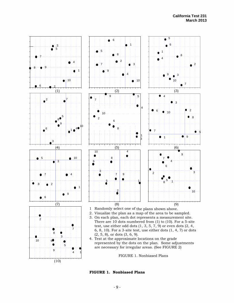
2. For areas greater than 1,000 yd2, select a minimum of five test sites by using a
set of nonbiased sample plans shown in Figure 1. Follow instructions given in Figure 1. No test may represent more than 2,000 yd2. If the designated test area is equal to or less than 1,000 yd2 (e.g., structure backfill, short length of shoulders, or others), a minimum of three test sites are required.
3. Obtain nuclear counts at all test sites and average all counts for the area
(Form TL 2148).
2B. DETERMINATION OF WET TEST MAXIMUM DENSITY
1. For all treated and untreated soils and aggregates, except Class A Cement Treated Base (CTB), obtain equal representative portions of material from each nuclear test site within the tested area and thoroughly mix together to form a composite sample in accordance with California Test 216.
2. Determine the laboratory wet test maximum density (g/cc) (composite wet test
maximum density on the composite sample in accordance with California Test 216). Record the data on Form TL 2148 in the section identified as “IMPACT TEST DATA.” (See Example in Figure 4.)
NOTE: The moisture content of the composite sample must be maintained in the
same state as when the in-place tests were performed.
2C. CORRECTION FOR OVERSIZE MATERIAL
1. Apply a rock correction to the composite wet test maximum density in instances where the composite sample contains more than 10 % by weight of aggregate retained on the ¾ in. sieve.
2. Record data on Form TL 2148 in the section titled “Sample for Rock Correction.” 3. Plot the moisture-density relationship as determined in California Test 216 on
the graph provided on Form TL 2148. Indicate the corrected density on the plot as a dot with a circle labeled “Adjusted Density.”
2D. PERCENT RELATIVE COMPACTION
1. Calculate the percent relative compaction as follows:
100DensityMaximum TestWet Composite
Density Wet Place-In Average(%)CompactionelativeR ×=
2. Calculate the percent relative compaction value to the nearest 0.1 % and report
as a whole number. Round the average percent relative compaction value (Test Result) as follows.
California Test 231 March 2013
- 5 -
If the computed value ends in a number with a fractional portion 0.5 % or greater, report as the next higher whole number. If the computed value ends in a number with a fractional portion less than 0.5 %, report the whole number without change. NOTE: Gage readings for the individual sites are averaged and a mean percent
relative compaction is calculated for the area.
2E. WET COMMON-COMPOSITE TEST MAXIMUM VALUE
1. In cases where the material is the “same”, it is permissible to use a “common” wet composite test maximum density in other tested areas in lieu of that specified in Section 2B. For a material to be the “same”, it must comply with the following general criteria:
a. The soil must be from the same general source (excavation area, balance
point, plant, etc.). b. The soil must generally have the same visual characteristics of color,
gradation, and type of soil. c. The average in-place moistures must be the “same." Adjustments in
moisture are to be made to meet these criteria when “common” wet composite test maximum values are used.
2. A “common” wet composite test maximum density is initially established by
averaging two consecutive wet composite test maximum densities within 0.05 g/cc and performed within three days. The average moistures between the areas represented by the two consecutive wet composite test maximum values must also be within 0.05 g/cc.
3. Use the wet composite test maximum density determined for an area to calculate
the percent relative compaction for that area. 4. A “check” wet composite test maximum must be performed at least every
7th calendar day or after the “common” wet composite test maximum density has been used for 14 areas, whichever comes first.
NOTE: If the “check” test is within 0.05 g/cc of the current “common” density
and moisture values, the two values are averaged to establish a new “common” density and average moisture. If the “check” is not within 0.05 g/cc of the current common values, a wet composite test maximum density must be performed for each compaction test area until the criteria in Section 2E.2 are met.
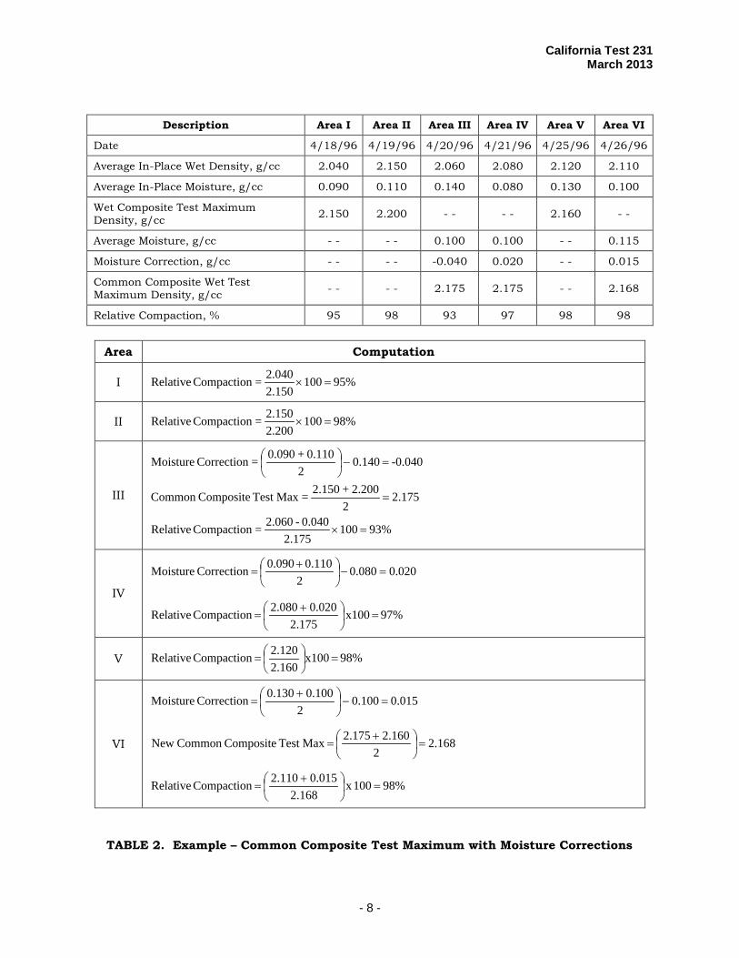
5. If average moistures between areas differ and a common composite test
maximum density is to be established, a correction is applied. Establish a new common composite test maximum when the engineer determines there is a change in area conditions. Table 2 illustrates an example using a common composite test maximum density with moisture corrections.
California Test 231 March 2013
- 6 -
D. HEALTH AND SAFETY Follow all rules and regulations in the operator’s manual and the Radioactive Materials License issued by the California Department of Public Health under Title 17, California Code of Regulations, Division 1, Chapter 5, Subchapters 4.0, 4.5, and 4.6. It is the responsibility of the user of this test method to establish appropriate safety and health practices and determine the applicability of regulatory limitations prior to use. Prior to handling, testing or disposing of any materials, testers must be knowledgeable about safe laboratory practices, hazards and exposure, chemical procurement and storage, and personal protective apparel and equipment. Caltrans Laboratory Safety Manual is available at:
Users of this test method do so at their own risk.
End of Text (California Test 231 contains 12 pages)
California Test 231 March 2013
- 7 -
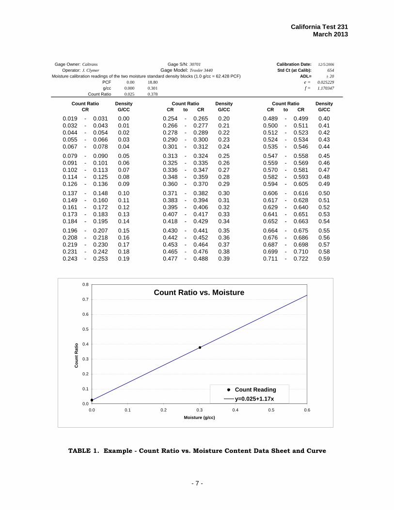
Gage Owner: Caltrans Gage S/N: 30701 Calibration Date: 12/5/2006Operator: J. Clymer Gage Model: Troxler 3440 Std Ct (at Calib): 654
Moisture calibration readings of the two moisture standard density blocks (1.0 g/cc = 62.428 PCF) ADL= ± 20PCF 0.00 18.80 e = 0.025229g/cc 0.000 0.301 f = 1.170347
Count Ratio 0.025 0.378
Count Ratio Density Count Ratio Density Count Ratio DensityCR G/CC CR to CR G/CC CR to CR G/CC
0.019 - 0.031 0.00 0.254 - 0.265 0.20 0.489 - 0.499 0.400.032 - 0.043 0.01 0.266 - 0.277 0.21 0.500 - 0.511 0.410.044 - 0.054 0.02 0.278 - 0.289 0.22 0.512 - 0.523 0.420.055 - 0.066 0.03 0.290 - 0.300 0.23 0.524 - 0.534 0.430.067 - 0.078 0.04 0.301 - 0.312 0.24 0.535 - 0.546 0.440.079 - 0.090 0.05 0.313 - 0.324 0.25 0.547 - 0.558 0.450.091 - 0.101 0.06 0.325 - 0.335 0.26 0.559 - 0.569 0.460.102 - 0.113 0.07 0.336 - 0.347 0.27 0.570 - 0.581 0.470.114 - 0.125 0.08 0.348 - 0.359 0.28 0.582 - 0.593 0.480.126 - 0.136 0.09 0.360 - 0.370 0.29 0.594 - 0.605 0.490.137 - 0.148 0.10 0.371 - 0.382 0.30 0.606 - 0.616 0.500.149 - 0.160 0.11 0.383 - 0.394 0.31 0.617 - 0.628 0.510.161 - 0.172 0.12 0.395 - 0.406 0.32 0.629 - 0.640 0.520.173 - 0.183 0.13 0.407 - 0.417 0.33 0.641 - 0.651 0.530.184 - 0.195 0.14 0.418 - 0.429 0.34 0.652 - 0.663 0.540.196 - 0.207 0.15 0.430 - 0.441 0.35 0.664 - 0.675 0.550.208 - 0.218 0.16 0.442 - 0.452 0.36 0.676 - 0.686 0.560.219 - 0.230 0.17 0.453 - 0.464 0.37 0.687 - 0.698 0.570.231 - 0.242 0.18 0.465 - 0.476 0.38 0.699 - 0.710 0.580.243 - 0.253 0.19 0.477 - 0.488 0.39 0.711 - 0.722 0.59
Count Ratio vs. Moisture
0.0
0.1
0.2
0.3
0.4
0.5
0.6
0.7
0.8
0.0 0.1 0.2 0.3 0.4 0.5 0.6
Moisture (g/cc)
Cou
nt R
atio
Count Readingy=0.025+1.17x
TABLE 1. Example - Count Ratio vs. Moisture Content Data Sheet and Curve
California Test 231 March 2013
- 8 -
Description Area I Area II Area III Area IV Area V Area VI
Date 4/18/96 4/19/96 4/20/96 4/21/96 4/25/96 4/26/96
Average In-Place Wet Density, g/cc 2.040 2.150 2.060 2.080 2.120 2.110
Average In-Place Moisture, g/cc 0.090 0.110 0.140 0.080 0.130 0.100
Wet Composite Test Maximum Density, g/cc 2.150 2.200 - - - - 2.160 - -
Average Moisture, g/cc - - - - 0.100 0.100 - - 0.115
Moisture Correction, g/cc - - - - -0.040 0.020 - - 0.015
Common Composite Wet Test Maximum Density, g/cc - - - - 2.175 2.175 - - 2.168
Relative Compaction, % 95 98 93 97 98 98
Area Computation
I 95%1002.1502.040=Compaction Relative =×
II 98%1002.2002.150=Compaction Relative =×
III
93%1002.175
0.040-2.060=Compaction Relative
2.1752
2.200+2.150=MaxTest CompositeCommon
-0.040140.02
0.110+0.090=Correction Moisture
=×
=
=−
IV
020.0080.02
110.00.090 Correction Moisture =−
+
=
97% x100175.2
200.02.080 Compaction Relative =
+
=
V 98% x100160.2
2.120 Compaction Relative =
=
VI
015.0100.02
100.00.130 Correction Moisture =−
+
=
168.22
2.1602.175 Max Test CompositeCommon New =
+
=
98%100x 168.2
015.02.110 Compaction Relative =
+
=
TABLE 2. Example – Common Composite Test Maximum with Moisture Corrections
California Test 231 March 2013
- 9 -
(1)
(2)
(3)
(4)
(5)
(6)
(7)
(8)
(9)
(10)
1 Randomly select one of the plans shown above. 2. Visualize the plan as a map of the area to be sampled. 3. On each plan, each dot represents a measurement site.
There are 10 dots numbered from (1) to (10). For a 5-site test, use either odd dots (1, 3, 5, 7, 9) or even dots (2, 4, 6, 8, 10). For a 3-site test, use either dots (1, 4, 7) or dots (2, 5, 8), or dots (3, 6, 9).
4. Test at the approximate locations on the grade represented by the dots on the plan. Some adjustments are necessary for irregular areas. (See FIGURE 2)
FIGURE 1. Nonbiased Plans
1
2
3
4
5 6
7 8
9
10
1
2 3
4
5
6
7
8
9
10
1
2 3
4
5
6
7
8
9
10
1
2
3
4
5
6
7
8
9
10
1 2
3
4
5
6
7
8
9
10
1
2
3
4
5
6
7
8
9
10
1
2
3
4
5
6
7
8
9
10
1
2
3
4
5
6
7
8 9
10
1
2
3
4
5
6
7
8
9
10
1
2
3
4
5
6
7
8 9
10
FIGURE 1. Nonbiased Plans

California Test 231 March 2013
- 10 -
FIGURE 2. Adjustment for Irregular Areas
1
9
8
7
5
4
10
2
6
3
4
9
6
8
7
1 1
5
3
2
5
8
3
9
6
7
1
2
4
10
10

California Test 231 March 2013
- 11 -
FIGURE 3. Form TL 2148
California Test 231 March 2013
- 12 -
FIGURE 4. Example of a Completed Form TL 2148
0